US7063703B2 - Slip-fit handle for hand-held instruments that access interior body regions - Google Patents
Slip-fit handle for hand-held instruments that access interior body regionsDownload PDFInfo
- Publication number
- US7063703B2 US7063703B2US10/227,714US22771402AUS7063703B2US 7063703 B2US7063703 B2US 7063703B2US 22771402 AUS22771402 AUS 22771402AUS 7063703 B2US7063703 B2US 7063703B2
- Authority
- US
- United States
- Prior art keywords
- instrument
- handle
- guide pin
- obturator
- cannula
- Prior art date
- Legal status (The legal status is an assumption and is not a legal conclusion. Google has not performed a legal analysis and makes no representation as to the accuracy of the status listed.)
- Expired - Fee Related, expires
Links
Images


Classifications
- A—HUMAN NECESSITIES
- A61—MEDICAL OR VETERINARY SCIENCE; HYGIENE
- A61B—DIAGNOSIS; SURGERY; IDENTIFICATION
- A61B17/00—Surgical instruments, devices or methods
- A61B17/16—Instruments for performing osteoclasis; Drills or chisels for bones; Trepans
- A61B17/1662—Instruments for performing osteoclasis; Drills or chisels for bones; Trepans for particular parts of the body
- A61B17/1671—Instruments for performing osteoclasis; Drills or chisels for bones; Trepans for particular parts of the body for the spine
- A—HUMAN NECESSITIES
- A61—MEDICAL OR VETERINARY SCIENCE; HYGIENE
- A61B—DIAGNOSIS; SURGERY; IDENTIFICATION
- A61B17/00—Surgical instruments, devices or methods
- A61B17/16—Instruments for performing osteoclasis; Drills or chisels for bones; Trepans
- A—HUMAN NECESSITIES
- A61—MEDICAL OR VETERINARY SCIENCE; HYGIENE
- A61B—DIAGNOSIS; SURGERY; IDENTIFICATION
- A61B17/00—Surgical instruments, devices or methods
- A61B2017/0046—Surgical instruments, devices or methods with a releasable handle; with handle and operating part separable
- A61B2017/00464—Surgical instruments, devices or methods with a releasable handle; with handle and operating part separable for use with different instruments
- A—HUMAN NECESSITIES
- A61—MEDICAL OR VETERINARY SCIENCE; HYGIENE
- A61B—DIAGNOSIS; SURGERY; IDENTIFICATION
- A61B17/00—Surgical instruments, devices or methods
- A61B2017/0046—Surgical instruments, devices or methods with a releasable handle; with handle and operating part separable
- A61B2017/00469—Surgical instruments, devices or methods with a releasable handle; with handle and operating part separable for insertion of instruments, e.g. guide wire, optical fibre
- A—HUMAN NECESSITIES
- A61—MEDICAL OR VETERINARY SCIENCE; HYGIENE
- A61B—DIAGNOSIS; SURGERY; IDENTIFICATION
- A61B17/00—Surgical instruments, devices or methods
- A61B2017/00477—Coupling
Definitions
- the inventiongenerally relates to hand-held surgical instruments and to procedures that deploy these instruments through tissue to access interior regions of the body.
- a single surgical procedurewill require the physician to employ different surgical instruments, each possessing a different shape, size, and function.
- the procedurewill require the physician to deploy these instruments in both soft and hard tissue to meet the diagnostic or therapeutic objectives of the procedure.
- the physicianwill often need an enhanced mechanical advantage to advance an instrument through tissue, particularly through dense or hard tissue, such as bone.
- One aspect of the inventionprovides a surgical system comprising a cannula instrument, a guide pin instrument, and a handle.
- the cannula instrumenthas a bore extending therethrough and includes a handle attachment site.
- the guide pin instrumentis sized and configured for passage through the bore of the cannula instrument.
- the handleis adapted for manipulating the cannula instrument when in use.
- the handleincludes a component configured to removably engage the handle attachment site and further includes a passageway in the handle that accommodates passage of the guide pin instrument through the bore of the cannula instrument while the cannula instrument is removably engaged by the handle.
- the guide pin instrumentincludes a handle.
- the systemfurther comprises a third functional instrument sized for passage through the bore of the cannula instrument after the guide pin instrument is removed from the bore of the cannula.
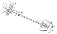
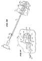
- FIG. 1is a perspective view of a system including different functional instruments and a T-shaped handle that slip-fits into and out of engagement with the instruments, to aid a physician in manipulating the instruments during use;
- FIG. 2is an enlarged perspective view of a first type of tapered flange, carried by at least one of the instruments shown in FIG. 1 , which slip-fits into and out of the handle;
- FIG. 3is an enlarged perspective view of a second type of tapered flange, carried by at least one of the instruments shown in FIG. 1 , which slip-fits into and out of the handle;
- FIG. 4an end view of the tapered flange shown in FIG. 3 , taken generally along line 4 — 4 in FIG. 3 ;
- FIG. 5is a top view of the T-shaped handle shown in FIG. 1 ;
- FIG. 6is a side view of the T-shaped handle shown in FIG. 5 ;
- FIG. 7is a bottom view of the T-shaped handle shown in FIG. 5 , showing the first and second sockets of the handle;
- FIG. 8is a side perspective view of the handle shown in FIG. 5 , being grasped by a physician and ready for use;
- FIG. 9is a perspective view of an obturator instrument having a tapered flange of the type shown in FIG. 2 slip-fitted into the first socket of the handle shown in FIGS. 5 to 8 , ready for use;
- FIG. 10is an enlarged perspective view, with portions broken away, showing the details of the slip fit engagement between the tapered flange and the first handle socket shown in FIG. 9 ;
- FIG. 11is a perspective view of a cannula instrument having a tapered flange of the type shown in FIGS. 3 and 4 slip-fitted into the second socket of the handle shown in FIGS. 5 to 8 , ready for use;
- FIG. 12is an enlarged perspective view, with portions broken away, showing the details of the slip fit engagement between the tapered flange and the second handle socket shown in FIG. 11 ;
- FIG. 13is an enlarged view of the geometries of first and second sockets of the handle shown in FIGS. 5 to 8 ;
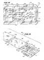
- FIG. 14is a top view of a kit for storing the one or more functional instruments in association with the handle shown in FIGS. 5 to 8 prior to use;
- FIG. 15is an exploded perspective view of the kit shown in FIG. 14 ;
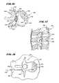
- FIGS. 16 and 17are, respectively, top and side views of a human vertebral body
- FIG. 18is a top view of a vertebral body during insertion of a spinal needle assembly to begin a bone access procedure
- FIGS. 19 to 21are top views showing subsequent steps, after insertion of the spinal needle assembly shown in FIG. 18 , of inserting a guide pin component into the vertebral body;
- FIG. 22is a perspective view showing a subsequent step, after insertion of the guide pin component shown in FIGS. 19 to 21 , which uses the handle shown in FIGS. 5 to 8 to aid in the deployment of an obturator instrument over the guide pin component;
- FIG. 23is a top view of the vertebral body, with the obturator instrument shown in FIG. 22 deployed;
- FIG. 24is a perspective view showing a subsequent step, after insertion of the obturator instrument shown in FIG. 22 , which uses the handle shown in FIGS. 5 to 8 to aid in the deployment of a cannula instrument over the obturator instrument;
- FIG. 25is a top view of the vertebral body, with the cannula instrument shown in FIG. 24 deployed;
- FIG. 26is a perspective view showing a subsequent step, after insertion of the cannula instrument shown in FIG. 24 , which removes the obturator instrument from the cannula instrument, to leave the cannula instrument and guide pin component in place;
- FIG. 27is a top view of the vertebral body, after the obturator removal step shown in FIG. 26 , leaving the cannula instrument and guide pin component in place;
- FIG. 28is a perspective view showing a subsequent step, after removal of the obturator instrument shown in FIG. 26 , which uses the handle shown in FIGS. 5 to 8 to aid in the deployment of a drill bit instrument through the cannula instrument along the guide pin component;
- FIG. 29is a top view of the vertebral body, as the drill bit instrument shown in FIG. 28 is deployed with aid of the handle to open a passage into the interior volume of the vertebral body;
- FIG. 30is a perspective view showing a subsequent step, after removal of the drill bit instrument and guide pin component shown in FIG. 28 , of deploying a catheter instrument carrying a diagnostic or therapeutic element through the cannula instrument into the vertebral body;
- FIG. 31is a top view of the vertebral body, as the diagnostic or therapeutic element carried by the catheter component shown in FIG. 30 is deployed into the interior volume of the vertebral body;
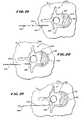
- FIG. 32is a top view of a round handle, which can be used in association with the functional instruments shown in FIG. 1 , in generally the same fashion as the T-shaped handle shown in FIGS. 5 to 8 ;
- FIG. 33is a side view of the round handle shown in FIG. 32 ;
- FIG. 34is a bottom view of the round handle shown in FIG. 32 , showing the first and second sockets of the handle;
- FIG. 35is a perspective view of an elliptical, anvil-style handle, which can be used in association with the functional instruments shown in FIG. 1 when greater tapping or compression force is required to advance an instrument, particularly through hard tissue, like bone;
- FIG. 36is a rear side perspective view of the anvil-style handle shown in FIG. 35 , showing the first and second sockets of the handle;
- FIG. 37is a rear elevation view of the anvil-style handle shown in FIG. 35 , showing the first and second sockets of the handle;
- FIG. 38is a front elevation view of the anvil-style handle shown in FIG. 35 ;
- FIG. 39is a perspective view of an alternative system including different functional instruments and a T-shaped handle that slip-fits into and out of engagement with the instruments, to aid a physician in manipulating the instruments during use.
- FIG. 1shows a system 10 for penetrating tissue.
- the systemincludes one or more functional instruments 12 , 14 , and 16 and a handle 18 .
- the handle 18engages at least one of the functional instruments 12 , 14 , and 16 in a removable, slip fit fashion to aid a physician in manipulating the instrument 12 , 14 , or 16 during use.
- FIG. 1shows three representative instruments 12 , 14 , and 16 , each having a different size and function.
- the first, second, and third instruments 12 , 14 , and 16share some common features, although they are intended, in use, to perform different functions.
- the first, second and third instrument 12 , 14 , and 16each comprises an elongated, cylindrical body 20 having a proximal end 22 and a distal end 24 .
- the first, second, and third instrument 12 , 14 , and 16are each made of a rigid, surgical grade plastic or metal material.
- the first instrument 12functions as an obturator. Its distal end 24 is tapered to present a penetrating surface 26 . In use, the surface 26 is intended to penetrate soft tissue in response to pushing or twisting forces applied by the physician at the proximal end 22 .
- the proximal end 22 of the obturator instrument 12presents a flanged surface 28 .
- the flanged surface 28tapers from a larger outer diameter to a smaller outer diameter in the direction of the proximal end 22 .
- the flanged surface 28includes an array of circumferentially spaced teeth 30 with intermediate flutes 32 .
- An interior lumen 34extends through the obturator instrument 12 from the distal end 24 to the proximal end 22 .
- the interior lumen 34is sized to accommodate a conventional surgical guide pin component to aid in its deployment, as will be described in greater detail later.
- the second instrument 14functions as a cannula or guide sheath.
- the cannula instrument 14is somewhat larger in diameter than and not as long as the obturator instrument 12 .
- the cannula instrument 14includes an interior lumen 36 that extends from its distal end 24 to its proximal end 22 .
- the interior lumen 36is sized to accept the obturator instrument 12 .
- the size of the interior lumen 36permits a physician to slide and rotate the cannula instrument 14 relative to the obturator instrument 12 , and vice versa, as will be described in greater detail later.
- the distal end 24 of the cannula instrument 14presents an end surface 38 .
- the end surface 38 of the cannula instrument 14is intended to penetrate soft tissue surrounding the obturator instrument 12 , in response to pushing or twisting forces applied at the proximal end 22 .
- the proximal end 22carries an enlarged fitting 40 .
- the fitting 40tapers from a larger diameter to a smaller diameter in the direction of the proximal end 22 .
- the tapered fitting 40has an array of circumferentially spaced teeth 42 with intermediate flutes 44 .
- the tapered fitting 40 of the cannula instrument 14possesses a larger maximum outer diameter than the maximum outer diameter of the tapered flange 28 of the obturator instrument 12 .
- the third instrument 16functions as a drill bit.
- the drill bit instrument 16has generally the same physical dimensions as the obturator instrument 12 .
- the drill bit instrument 16is intended, in use, to fit for sliding and rotational movement within the interior lumen 36 of the cannula instrument 14 .
- the distal end 24 of the drill bit instrument 16includes machined cutting edges 46 .
- the cutting edges 46are intended to penetrate hard tissue in response to rotation and longitudinal load forces applied at the proximal end 22 of the drill bit instrument 16 .
- the proximal end 22presents a tapered flange 28 , substantially identical to the flange 28 on the obturator instrument 12 , as FIG. 2 shows in an enlarged view.
- the tapered flange 28changes from a larger diameter to a smaller diameter in the direction of the proximal end 22 .
- the tapered flange 28 of the drill bit instrument 16also includes an array of circumferentially spaced teeth 30 with intermediate flutes 32 .
- the form and orientation of the teeth 30 and flutes 32 on the drill bit instrument 16correspond to the form and orientation of the teeth 30 and flutes 32 on the obturator instrument 12 .
- the handle 18is made from a molded or cast rigid plastic or metal material. As also shown in FIGS. 5 to 8 , the handle 18 is shaped to be comfortably and securely grasped by a normal human hand (see FIG. 8 ). The shape and size to accommodate this function can, of course, vary. In the embodiment shown in FIG. 5 , the handle 18 is elongated along a main axis 48 to fit comfortably across the palm of the hand. In a representative embodiment, the handle 18 measures about 76 mm in length along the main axis 48 , about 16 mm in width across the main axis 48 , and about 25 mm in height normal to the main axis 48 . These dimensions can, of course, vary to best serve the intended field of use.
- the handle 18includes a top wall 50 , opposed side walls 52 , and opposed end walls 54 .
- the junctions 56 of the side walls 52 and end walls 54 with the top wall 50are preferably rounded according to normal finger joint radii to provide a comfortable gripping area.
- the side walls 52 and end walls 54also taper somewhat outward from the top wall 50 (see FIGS. 6 and 8 ), to enable firm, comfortable grasping between the fingers and thumb, as FIG. 8 shows.
- the top wall 50 and side walls 52can be roughened or otherwise textured to provide a secure gripping surfaces.
- the contours of the handle 18are also designed to minimize surgical glove tears.
- the handle 18includes a center post 58 , which is integrally molded to the handle 18 about its geometric center 60 (as FIG. 6 shows).
- the center post 58extends downward from the top wall 50 along the geometric center 60 between the side walls 52 .
- the center post 58has an exposed end surface 62 , which terminates below the lower edges 64 of the side and end walls 52 and 54 . This gives the handle 18 a general T-shape, when viewed from the side (see FIGS. 6 and 8 ).
- the underside interior 66 of the handle 18includes a crossing array of molded stiffening ribs 68 and 70 extending about the center post 58 (as best shown in FIG. 7 ).
- Long stiffening ribs 68extend between the center post 58 and the end walls 54 , along the main axis 48 of the handle 18 .
- Cross ribs 70extend across the long ribs 68 between the side walls 52 .
- the ribs 68 and 70provide the handle 18 with structural rigidity and strength to transmit, without failure, both longitudinal and torsional load forces.
- the handle 18includes at least one interior cavity or socket 80 / 86 in the center post 58 .
- the socket 80 / 86serves to guide the attachment between the handle 18 and at least one of the instruments 12 , 14 , and 16 .
- the number of sockets 80 / 86can vary.
- the illustrated embodimentshows two sockets 80 and 86 . In this arrangement, each instrument 12 , 14 , and 16 in the system 10 can be fitted to the handle 18 .
- Both first and second sockets 80 and 86open at the end surface 62 of the center post 58 .
- Both sockets 80 and 86(see FIG. 6 ) include interior side walls 76 , which extend into the center post 58 .
- Both sockets 80 and 86include interior end walls 78 in the center post 58 , spaced below the top wall 50 of the handle 18 .
- the interior side wall 76 of the first socket 80includes an array of circumferentially spaced grooves 82 with intermediate splines 84 .
- the form and orientation of the grooves 82 and splines 84are sized to match the form and orientation of the teeth 30 and flutes 32 at the proximal ends 22 of the obturator instrument 12 and the drill bit instrument 16 .
- the first socket 80accepts the tapered flange 28 of either the obturator instrument 12 or the drill bit instrument 16 .
- the teeth 30 of the tapered flange 28mesh in a slip-fit with the grooves 82 of the first socket 80 .
- the running slip-fitallows longitudinal force to be applied to either instrument 12 or 16 through the handle 18 .
- the running slip-fitalso prevents relative rotation between either instrument 12 or 16 and the first socket 80 , thereby permitting torsional or twisting forces to be applied to either instrument 12 or 16 by the handle 18 , with an increased mechanical advantage.
- the tapered fitting 40 of the cannula instrument 14will not fit inside the first socket 80 . Instead (see FIGS. 11 and 12 ), the interior side wall 76 of the second socket 86 is sized to accept the tapered fitting 40 .
- the second socket 86includes an array of circumferentially spaced grooves 88 with intermediate edges 90 , which, in form and orientation, match the form and orientation of the teeth 42 and flutes 44 on the tapered fitting 40 .
- the teeth 42 of the tapered fitting 40mesh in a slip-fit with the grooves 88 of the second socket 86 , as FIG. 12 shows.
- the running slip-fitallows both longitudinal and torsional forces to be applied to the cannula instrument 14 through the handle, with increased mechanical advantage.
- the tapered flange 28 of either the obturator instrument 12 or the drill bit instrument 16will fit inside but not mesh with the second socket 86 .
- the first and second sockets 80 and 86thereby represent unique attachment sites for different functional instruments.
- a first passage 92extends through the top wall 50 of the handle 18 , through the center post 58 , and into the first socket 80 .
- the passage 92is generally aligned with the center of the first socket 80 within the cavity 72 .
- the first passage 92is sized to pass a conventional surgical guide wire component through the handle 18 and into the lumen 34 of the obturator instrument 12 , when fitted in the first socket 80 .
- the interior side wall 76 of the first socket 80is preferably tapered inward toward the first passage 92 , to guide the guide wire through the socket 80 into the first passage 92 without sticking. This arrangement will be described in greater detail later.
- a second passage 96extends through the top wall 50 of the handle 18 , through the center post 58 , and into the second socket 86 .
- the passage 96is generally aligned with the center of the second socket 86 .
- the second passage 96is sized to pass either the obturator instrument 12 or the drill bit instrument 16 through the handle 18 and into the lumen 36 of the cannula instrument 14 , when fitted in the second socket 86 . This arrangement will also be described in greater detail later.
- the form and function of the running slip-fit between the teeth and flutes 30 / 32 or 42 / 44 on the selected instruments 12 , 14 , and 16 and the grooves and splines 82 / 84 in the corresponding sockets 80 and 86allow the physician to fit the selected instrument 12 , 14 , or 16 to the handle 18 tactilely, without need of visual tracking or confirmation.
- the form and function of the running slip-fitmake possible the reliable transmission, with increased mechanical advantage, of both torsional and longitudinal loads by the handle 18 to the selected instrument 12 , 14 , or 16 , without undue slippage or wasted motion.
- the form and function of the running slip-fitpermit quick detachment of the selected instrument 12 , 14 , or 16 from the handle 18 , without sticking or resort to inordinate force.
- each groove 82comprises an arcuate section 100 that extends between two radial sections 102 .
- Each spline 84is defined between the radial sections 102 of two adjacent grooves 82 .
- the sockets 80 and 86 of the handle 18can possess different sizes and arcuate relationships, smaller or larger, according to the intended use. For example, posterolateral access to a vertebral body is made using instruments having a larger dimension than instruments used to accomplish a transpedicular access.
- the sockets 80 and 86 on the handle 18will therefore be sized differently, depending upon the dimensions of the mating instruments. Practicality and functionality dictate the minimum and maximum dimensions.
- the size and circumferential spacing of the sockets 80 and 86 , as well as the overall dimensions of the handle 18 itself,are selected based upon desired performance, manufacturing, and ease of use criteria.
- the arcuate sections 100 of the grooves 82lay at a diameter of about 5.2 mm and the splines 84 lay at a diameter of about 3.3 mm, measured from the center 94 of the first socket 80 .
- the arcuate sections 100 of the grooves 82lay along a diameter of about 12.8 mm and the splines 84 lay along a diameter of about 8.1 mm, measured from the center 98 of the second socket 86 .
- the first passage 92has a diameter of about 1.8 mm
- the second passage 96has a diameter of about 6.5 mm.
- the center post 58has a major diameter of about 22.8 mm and a minor diameter of about 15.8 mm.
- the center 94 of the first socket 80is spaced inward along the main axis 48 from one side of the center post 58 by about 17 mm, while the center 98 of the second socket 86 is spaced inward along the main axis 48 from the same side by about 7.6 mm.
- the arcuate sections 100 of the grooves 82lay at a diameter of about 3.0 mm and the splines 84 lay at a diameter of about 1.9 mm, measured from the center 94 of the first socket 80 .
- the arcuate sections 100 of the grooves 82lay along a diameter of about 7.4 mm and the splines 84 lay along a diameter of about 4.7 mm, measured from the center 98 of the second socket 86 .
- the first passage 92has a diameter of about 1.0 mm
- the second passage 96has a diameter of about 3.7 mm.
- the center post 58has a major diameter of about 22.8 mm and a minor diameter of about 15.8 mm.
- the center 94 of the first socket 80is spaced inward along the main axis 48 from one side of the center post 58 by about 17.0 mm, while the center 98 of the second socket 86 is spaced inward along the main axis 48 from the same side by about 7.6 mm.
- each groove 82extends over an equal arc GA of about 30°, and the grooves 82 are equally spaced apart by an arc SA of about 90°.
- the splines 84are circumferentially spaced apart by an equal arc EA of about 120°.
- the form and orientation of the teeth and flutes 30 / 32 and 42 / 44 on the mating instrument 12 , 16 , or 18are selected to match the form and orientation of the grooves and splines 82 / 84 of the appropriate socket 80 / 86 .
- the teeth and flutes 30 / 32 and 42 / 44have as their respective maximum outer diameters a dimension that is about 12% less than the maximum interior diameter of the mating groove and spline 82 / 84 , thereby providing a running slip fit, RC 8 .
- the form and function of the running slip-fitare also influenced by the relative size of the sockets 80 / 86 . Tactile placement is enhanced by maximizing the difference in socket size, so that fitting the wrong instrument in the wrong socket is eliminated. This, in turn, dictates the design of the mating instruments 12 , 14 , and 16 .
- the difference in socket sizesdictates the difference in sizes of the taper flanges 28 and fittings 40 on the various instruments 12 , 14 , and 16 .
- the close, side-by-side orientation of different size sockets 80 and 86coupled with the form and orientation of each socket 80 and 86 , allows for quick tactile recognition of the proper socket 80 / 86 on the handle 18 and quick tactile alignment of the mating tapered flanges 28 or tapered fittings 40 on the instrument 12 , 14 , and 16 in the identified socket 80 or 86 .
- the filleted splines 84allows for slip-fit engagement against the matching tapered flanges 28 or fittings 40 on the attached instrument 12 , 14 , or 16 .
- the filleted splines 84also allow ease of disengagement of the instrument 12 , 14 , and 16 from the handle 18 , without sticking.
- the form and orientation of the tapered flanges 28 or fittings 40also allow the application of torsional loads by the handle 18 about the axis of the attached instrument 12 , 14 , or 16 , while the handle 18 applies a longitudinal load along the axis of the attached instrument 12 , 14 , or 16 .
- a kit 104is provided for storing the one or more functional instruments 12 , 14 , and 16 in association with the handle 18 prior to use.
- the kit 104also includes other components 106 and 108 , which are intended to be used in association with the instruments 12 , 14 , and 16 and handle 18 .
- the kit 104 shown in FIG. 14includes a guide pin component 106 and a catheter component 108 , which carries a diagnostic or therapeutic element 110 for deployment in the targeted interior body region.
- the kit 104can also include a conventional spinal needle assembly 152 , which will be described in greater detail later.
- the kit 104can take various forms.
- the kit 104comprises a sterile, wrapped assembly.
- the kit 104includes an interior tray 112 made, e.g., from die cut cardboard, plastic sheet, or thermo-formed plastic material.
- the tray 112includes spaced apart tabs 114 , which hold the handle 18 , instruments 12 , 14 , and 16 , and components 106 and 108 in a secure position during sterilization and storage prior to use.
- the tray 112presents the handle 18 , instruments 12 , 14 , and 16 , and components 106 and 108 in an ordered, organized layout, which is arranged to aid the physician in carrying out the intended procedure.
- the layout of the tray 112can present the instruments 12 , 14 , and 16 and components 106 and 108 in top-to-bottom order, according to sequence of intended use.
- the guide pin component 106is deployed first, followed by the obturator instrument 12 , then the cannula instrument 14 , then the drill bit instrument 16 , and lastly the catheter component 108 .
- the tray 112packages these instruments and components in a top-to-bottom order, with the guide pin component 106 topmost, the obturator instrument 12 next, the cannula instrument 14 next, the drill bit instrument 16 next, and the catheter component lowermost 108 .
- the spinal needle assembly 152is mounted above the guide pin component 106 .
- the handle 18is packaged to the side of the instruments 12 , 14 , and 16 .
- the tray 112can include written labels 116 identifying the handle 18 and each instrument and component contained in the kit 104 .
- the kit 104When packaged as a sterile assembly, the kit 104 includes an inner wrap 118 , which is peripherally sealed by heat or the like, to enclose the tray 112 from contact with the outside environment.
- One end of the inner wrapincludes a conventional peal-away seal 120 , to provide quick access to the tray 112 at the instant of use, which preferably occurs in a sterile environment, such as within an operating room.
- the kit 104When packaged as a sterile assembly, the kit 104 also includes an outer wrap 122 , which is also peripherally sealed by heat or the like, to enclosed the inner wrap.
- One end of the outer wrap 122includes a conventional peal-away seal 124 , to provide access to the inner wrap 118 and its contents.
- the outer wrap 122can be removed from the inner wrap 118 in anticipation of imminent use, without compromising sterility of the handle 18 , instruments 12 , 14 , and 16 , and components 106 and 108 themselves.
- Each inner and outer wrap 118 and 122includes a peripherally sealed top sheet 126 and bottom sheet 128 (see FIG. 15 ).
- the top sheet 126is made of transparent plastic film, like polyethylene or MYLARTM material, to allow visual identification of the contents of the kit 104 .
- the bottom sheet 128is made from a material that is permeable to ETO sterilization gas, e.g., TYVEKTM plastic material (available from DuPont).
- the kit 104also preferably includes in the tray 112 directions 130 for using the handle 18 , the instruments 12 , 14 , and 16 , and the components 106 and 108 to carry out a desired procedure.
- An exemplary procedure which the directions can describewill be explained later.
- the-directions 130can include the statement “For Single Patient Use Only” (or comparable language) to affirmatively caution against reuse of the contents of the kit 104 .
- the directions 130also preferably affirmatively instruct against resterilization of the handle 18 , instruments 12 , 14 , and 16 , or components 106 and 108 and also instructs the physician or user to dispose of the entire contents of the kit 104 upon use in accordance with applicable biological waste procedures.
- the presence of the handle 18 , instruments 12 , 14 , and 16 , and components 106 and 108 packaged in the sterile kit 104verifies to the physician or user that the contents are sterile and have not been subjected to prior use. The physician or user is thereby assured that the handle 18 , instruments 12 , 14 , and 16 , and components 106 and 108 meet established performance and sterility specifications.
- kit 104can be packaged into several, smaller functional kits.
- a tool kitcan package a spinal needle assembly, a guide pin component, an obturator instrument, a cannula instrument, and a drill bit instrument, together with the handle.
- a separate catheter kitcan package the catheter component.
- Another separate cement kitcan package a cement nozzle and tamp.
- FIGS. 14 and 15illustrate one of many different possible embodiments.
- the followingdescribes use of the handle 18 , instruments 12 , 14 , and 16 , and components 106 and 108 shown in FIG. 14 packaged in the kit 104 in the context of treating bones. This is because these items can be advantageously used for this purpose. Still, it should be appreciated that the handle 18 is not limited to use in the treatment of bones. The handle 18 can be used in association with virtually any hand-held instrument intended to contact tissue to perform a diagnostic or therapeutic function.
- the handle 18 , instruments 12 , 14 , and 16 , and components 106 and 108will described with regard to the treatment of human vertebra. It should be appreciated, however, their use is not limited to human vertebrae.
- the handle 18can be used in association with hand-held instruments in the treatment of diverse human or animal bone types.
- a typical vertebra 130includes a vertebral body 132 , which extends on the anterior (i.e., front or chest) side of the vertebra 130 .
- the vertebral body 132has the shape of an oval disk.
- the vertebral body 132includes an exterior formed from compact cortical bone 136 .
- the cortical bone 136encloses an interior volume 138 of reticulated cancellous, or spongy, bone 140 (also called medullary bone or trabecular bone).
- the spinal cord 142passes through the spinal canal of the vertebra 132 .
- the vertebral arch 144surrounds the spinal canal 142 .
- the pedicles 146 of the vertebral archadjoin the vertebral body 134 .
- the spinous process 148extends from the posterior of the vertebral arch 144 , as do the left and right transverse processes 150 .
- a patientlies on an operating table, while the physician introduces a conventional spinal needle assembly 152 into soft tissue (designated S in the drawings) in the patient's back.
- the patientcan lie facedown on the table, or on either side, or at an oblique angle, depending upon the physician's preference.
- the procedurecan be performed through an open anterior procedure or an endoscopic anterior procedure.
- the spinal needle assembly 152comprises a stylet 154 slidably housed within a stylus 156 .
- the assembly 152typically has, for example, about an 18 gauge diameter. Other gauge diameters can and will be used to accommodate appropriate guide pins.
- the physicianadvances the assembly 152 through soft tissue S down to and into the targeted vertebra 132 , as FIG. 18 shows.
- the physicianwill typically administer a local anesthetic, for example, lidocaine, through assembly 152 .
- a local anestheticfor example, lidocaine
- the physicianmay prefer other forms of anesthesia.
- the physiciandirects the spinal needle assembly 152 to penetrate the cortical bone 136 and the cancellous bone 140 of the targeted vertebra 132 .
- the depth of penetrationis about 60% to 95% of the vertebral body 134 .
- FIG. 18shows gaining access to cancellous bone 140 through the pedicle 146 , which is called transpedicular access.
- posterolateral accessthrough the side of the vertebral body 134 may be indicated, based upon the objectives of the treatment or for other reasons based upon the preference of the physician.
- the physicianholds the stylus 156 and withdraws the stylet 154 . It is at this time, or slightly before, that the outer and inner wraps 118 and 122 of the kit 104 can be removed, exposing the components carried on the tray 112 for use.
- the physicianfirst acquires the guide pin component 106 from the tray 112 .
- the physicianslides the guide pin component 106 through the stylus 156 and into the cancellous bone 140 .
- the physiciannow removes the stylus 156 , leaving the guide pin component 106 deployed within the cancellous bone 140 .
- the physiciannext acquires the obturator instrument 12 and the handle 18 from the tray 112 .
- the physicianslides the obturator instrument 12 over the guide pin component 106 , distal end first.
- the physicianslides the guide pin component 106 through the first passage 92 and the first socket 80 of the handle 18 .
- the interior side wall 76 of the first socket 80is preferably tapered inward to guide the guide wire into the first passage 92 without sticking.
- the physicianslides the handle 18 along the guide pin component 106 toward the tapered flange 28 of the obturator instrument 12 , until achieving a running slip-fit between the first socket 80 and the tapered flange 28 , in the manner previously described.
- the obturator instrument 12is now ready for use.
- the physicianmakes a small incision(designated I in FIG. 22 ) in the patient's back.
- the physiciantwists the handle 18 while applying longitudinal force to the handle 18 .
- the tapered surface 26 of the obturator instrument 12rotates and penetrates soft tissue through the incision I.
- the physicianmay also gently tap the handle 18 , or otherwise apply appropriate additional longitudinal force to the handle 18 , to advance the obturator instrument 12 through the soft tissue S along the guide pin component 106 down to the entry pedicle 146 .
- the physiciancan also tap the handle 18 with an appropriate striking tool to advance the sharpened surface 26 of the obturator instrument 12 into the pedicle 146 to secure its position, as FIG. 23 shows.
- the physiciannext slides the handle 18 along the guide pin component 106 away from the obturator instrument 12 to disengage the tapered flange 28 from the first socket 80 .
- the physicianthen proceeds to slide the handle 18 completely off the guide pin component 106 .
- the physicianacquires the cannula instrument 14 from the tray 112 .
- the physicianslides the cannula instrument 14 over the guide pin component 106 , distal end first, and, further, over the obturator instrument 12 , until contact between the end surface 38 and tissue occurs.
- the physiciannow slides the guide pin component 106 through the second passage 96 and second socket 86 of the handle 18 .
- the physicianslides the handle 18 toward the tapered fitting 40 of the cannula instrument 14 until a running slip-fit occurs between the second socket 86 and the tapered fitting 40 , as previously described.
- the cannula instrument 14is now ready for use.
- Fig. Fthe physician applies appropriate twisting and longitudinal forces to the handle 18 , to rotate and advance the cannula instrument 14 through soft tissue along the obturator instrument 12 .
- FIG. 25shows, when the end surface 38 of the cannula instrument 14 contacts cortical bone 136 , the physician appropriately taps the handle with a striking tool to advance the end surface 38 into the pedicle 146 to secure its position.
- FIG. 26shows, the physician now withdraws the obturator instrument 12 , sliding it off the guide pin component 106 , to leave the guide pin component 106 and the cannula instrument 14 in place, as FIG. 27 shows.
- the physicianslides the handle 18 along the guide pin component 106 away from the cannula instrument 14 to disengage the tapered fitting 40 from the second socket 86 .
- the physicianthen slides the handle 18 completely off the guide pin component 106 .
- the physiciannow acquires the drill bit instrument 16 from the tray 112 .
- the physicianslides the drill bit instrument 16 over the guide pin component 106 , distal end first, through the cannula instrument 14 until contact with the bone tissue occurs.
- the physiciannext leads the guide pin component 106 through the first passage 92 and first socket 80 of the handle 18 .
- the preferred taper of the first socket 80guides the guide wire through the socket 80 into the first passage 92 without sticking.
- the physicianslides the handle 18 along the guide pin component 106 toward the tapered flange 28 of the drill bit instrument 16 , until a running slip-fit occurs between the first socket 80 and the tapered flange 28 , as previously described.
- the drill bit instrument 16is now ready for use.
- FIG. 29shows, under X-ray control (or using another external visualizing system), the physician applies appropriate twisting and longitudinal forces to the handle 18 , to rotate and advance the cutting edge 46 of the drill bit instrument 16 to open a passage 158 through the bone tissue and completely into the cancellous bone 140 .
- the drilled passage 158preferable extends no more than 95% across the vertebral body 134 .
- the physiciannow slides the handle 18 along the guide pin component 106 away from the drill bit instrument 16 to disengage the tapered flange 28 from the first socket 80 .
- the physicianfurther, slides the handle 18 completely off the guide pin component 106 .
- the physiciancan now remove the drill bit instrument 16 and the guide pin component 106 , leaving only the cannula instrument 14 in place, as FIGS. 30 and 31 show.
- the passage 158 made by the drill bit instrument 16remains. Access to the cancellous bone 140 has been accomplished.
- the physiciancan now acquire the catheter component 108 from the tray 112 .
- the physiciancan advance a diagnostic or therapeutic element 110 carried by the catheter component 108 through the cannula instrument 14 and passage 158 into the interior volume 138 of the vertebral body 134 .
- the diagnostic or therapeutic element 110 of the catheter component 108can be configured to perform various functions.
- the distal element 110can comprise a biopsy instrument, to obtain samples of cancellous bone.
- the distal element 110can be a stylet to introduce a medication or the like into cancellous bone.
- the distal element 110can comprise an expandable body to compact cancellous bone 140 and form a cavity in the vertebral body 134 , in the manner disclosed in U.S. Pat. Nos. 4,969,888 and 5,108,404, which are incorporated herein by reference.
- the distal element 110can also include a nozzle to inject a flowable bone cement material into the formed cavity.
- FIGS. 5 to 8show a handle 18 with a generally T-shaped configuration.
- FIGS. 32 to 34show a representative alternative embodiment, in which a handle 218 has a general round configuration, made from a molded rigid plastic or metal material.
- the round handle 218is also shaped to be comfortably and securely grasped by a normal human hand.
- the handle 218measures about 38 mm in diameter.
- the handle 218includes a top wall 160 and a peripheral side wall 162 .
- the junction of the side wall 162 with the top wall 160is preferably rounded to provide a comfortable grip.
- the side wall 162includes a series of circumferentially spaced scallops 164 to assist the transmission of turning forces. In the illustrated embodiment, seven equally spaced scallops 164 are present to provide an appropriate turning resolution.
- the scallops 164are each curved inwardly to comfortable accommodate the dimension of a thumb (e.g., with a radius of curvature of about 9 mm to 10 mm).
- the top wall 160 and the side wall 162can be roughened or otherwise textured to enhance the over grip.
- the top wall 160includes circumferentially spaced voids 166 aligned with each scallop 164 .
- the voids 166reduce the overall weight of the handle 218 and are arranged to provide optimal balance for the handle 218 .
- the round handle 218includes a center post 168 , which is integrally molded to the walls 160 and 162 about the geometric center 170 of the handle 218 .
- the center post 168extends downward from the top wall 160 along the geometric center 170 between the side wall 162 .
- the center posthas an exposed end surface 172 , which terminates below the lower edge 176 of the side wall 162 .
- the center post 168has an outside diameter of about 22.8 mm, which is about the same outside diameter as the center post 58 of the T-shaped handle 18 .
- the round handle 218likewise includes the first and second sockets 80 and 86 to enable attachment of the various instruments, in the same manner as previously described.
- the sockets 80 and 86include arrays of grooves 82 circumferentially spaced by splines 84 .
- the form, orientation, and size of the grooves 82 and splines 84can be same as already described and shown in FIG. 13 to match the form and orientation of the teeth and flutes 30 / 32 and 42 / 44 at the proximal ends of the obturator instrument 12 and the drill bit instrument 14 (in the first socket 80 ) and the cannula instrument 12 (in the second socket 86 ).
- the tapered flanges 28 and fitting 40thereby mesh in a running slip-fit in the appropriate first and second sockets 80 and 86 .
- the comparable running slip-fit that the round handle 218 providesallows both longitudinal and twisting forces to be applied to the attached instrument 12 , 14 , and 16 through the handle 218 .
- the different sizes of the first and second sockets 80 and 86 on the round handle 218likewise represent the same sort of unique attachment sites for the different functional instruments, as previously explained for the T-shaped handle 18 .
- first and second passages 92 and 96extend through the top wall 160 of the round handle 218 and into the first and second sockets 80 and 86 , respectively.
- the first passage 92is sized to pass a conventional surgical guide wire through the handle 218 and into the lumen of the obturator instrument 12 or drill bit instrument 165 fitted in the first socket 80 .
- the second passage 96is sized to pass either the obturator instrument 12 or the drill bit instrument 16 through the handle 218 and through the lumen 36 of the cannula instrument 14 fitted in the second socket 86 .
- FIGS. 35 to 38show another alternative embodiment of a handle 318 , which embodies features of the invention.
- the handle 318is characterized by an elliptical “anvil” shape.
- the elliptical handle 318has a top wall 176 and a side wall 178 made from a molded rigid plastic or metal material.
- the handle 318is dimensioned to be grasped between the forefinger and the thumb, with the top wall 176 facing upward, as FIG. 35 shows.
- the shape and orientation, when held by the physician,are intended to facilitate the application of greater tapping or striking forces, to advance an attached instrument 12 / 14 / 16 through denser or harder tissue, such as skeleton bone.
- the top wall 176has a length dimension along it major axis 180 of about 57.2 mm and a length dimension along its minor axis 182 of about 50.8 mm.
- the side wall 178extends below the top wall 176 for a distance of about 11.3 mm.
- the side wall 178is chamfered inward, to present concave front and rear gripping surfaces 184 and 186 , which are spaced apart along the major axis 180 .
- the radius of chamfer for the front surface 184is intended to match the joint radius of the forefinger.
- the radius of the chamfer for the rear surface 186is intended to match the joint radius of the thumb.
- both the forward and rearward surfaces 184 and 186are knurled or roughed to enhance the physician's grip.
- the inward chamfer of the side wall 178shelters the physicians's hand from the top wall 176 , on which the striking forces are applied.
- the top wall 176is also preferably bowed upward, to present a raised striking surface, which further distances the physician's hand from the point of impact of the striking instrument.
- a portion of the rear gripping surface 186is cut away to form two interior sockets 188 and 190 .
- the sockets 188 and 190are axially oriented.
- the second socket 190possesses an interior dimension, which is larger than the interior dimension of the first socket 188 .
- the form and size of the first interior dimension of the first socket 188is intended to receive the proximal end 22 of either the obturator instrument 12 or the drill bit instrument 16 , but not the cannula instrument 14 , in a releasable interference snap-fit.
- the proximal end of the instrument 12 and 16can include a tapered flange 28 , as already described, but need not.
- the releasable snap-fitstabilizes the instrument 12 or 16 in the first socket 188 for the application of a striking force on the top wall 176 .
- the form and size of the second interior dimension of the second socket 190is intended to receive the proximal end 22 of the cannula instrument 14 , but not the obturator instrument 12 or the drill bit instrument 16 , in a releasable interference snap-fit.
- the proximal end 22 of the cannula instrument 14can include a tapered fitting 40 , as already described, but need not.
- the releasable snap-fitstabilizes the cannula instrument 14 in the second socket 190 for the application of a striking force on the top wall 176 .
- the handle 318will accommodate the passage of a guide pin component 106 and the like through any instrument attached to the handle 318 .
- the handle 318will also accommodate the passage of smaller diameter instrument within a larger diameter instrument held by the handle 318 .
- the form and orientation of the sockets 188 and 190 in the elliptical handle 318also permit the physician, using only tactile sensing, to insert the selected instrument into the desired socket 188 or 190 and remove the attached instrument from the socket 188 or 190 , without need of visual intervention.
- the sockets 80 and 86 shown in the T-shaped handle 18 in a side-by-side arrangementcan, in an alternative embodiment, be stacked one above the other in the manner shown for the anvil handle 318 in FIG. 36 .
- the smaller first socket 80is stacked concentrically above the larger second socket 86 .
- the passage 92extends along the center axis of the sockets 80 and 86 , opening into the first socket 80 and thereby serving both sockets 80 and 86 .
- This alternative constructionallows central placement of all the instruments carried by the handle.
- a handle 400can carry male handle attachment sites 402 and 404 that mate in the desired running slip fit fashion with female attachment components 406 , 408 , and 410 carried by the instruments 412 , 414 , and 416 , respectively.
- attachment site 402uniquely mates with the attachment components 406 and 410
- attachment site 404uniquely mates with attachment component 408 .
- the handle 400can carry one male attachment site and one female attachment component, and one instrument can likewise carry a male attachment site, while another instrument can carry a female attachment component. It should be fully appreciated that many attachment site/component combinations on the instruments and handle are possible. Regardless of the particular combination selected, the use of the handle 400 in association with the instruments 412 , 414 , and 416 is identical to that previously described in the context of other embodiments.
- the foregoing descriptiondemonstrates the applicability of a handle made according to the invention for use in association with a wide assortment of different instruments or tools, and for use both inside and outside the medical field.
- the handleprovides error-free coupling to different instruments or tools, and, further, uniquely allows coupling to one instrument or tool which has nested within it another instrument or tool.
- the shape and size of the handlecan also vary significantly, limited only by the practicalities surrounding hand-held use and manipulation.
Landscapes
- Health & Medical Sciences (AREA)
- Surgery (AREA)
- Life Sciences & Earth Sciences (AREA)
- Biomedical Technology (AREA)
- Medical Informatics (AREA)
- Orthopedic Medicine & Surgery (AREA)
- Oral & Maxillofacial Surgery (AREA)
- Engineering & Computer Science (AREA)
- Dentistry (AREA)
- Heart & Thoracic Surgery (AREA)
- Nuclear Medicine, Radiotherapy & Molecular Imaging (AREA)
- Molecular Biology (AREA)
- Animal Behavior & Ethology (AREA)
- General Health & Medical Sciences (AREA)
- Public Health (AREA)
- Veterinary Medicine (AREA)
- Surgical Instruments (AREA)
Abstract
Description
Claims (8)
Priority Applications (2)
| Application Number | Priority Date | Filing Date | Title |
|---|---|---|---|
| US10/227,714US7063703B2 (en) | 1998-01-27 | 2002-08-26 | Slip-fit handle for hand-held instruments that access interior body regions |
| US11/471,220US20060241627A1 (en) | 1998-01-27 | 2006-06-20 | Slip-fit handle for hand-held instruments that access interior body regions |
Applications Claiming Priority (2)
| Application Number | Priority Date | Filing Date | Title |
|---|---|---|---|
| US09/014,229US6468279B1 (en) | 1998-01-27 | 1998-01-27 | Slip-fit handle for hand-held instruments that access interior body regions |
| US10/227,714US7063703B2 (en) | 1998-01-27 | 2002-08-26 | Slip-fit handle for hand-held instruments that access interior body regions |
Related Parent Applications (1)
| Application Number | Title | Priority Date | Filing Date |
|---|---|---|---|
| US09/014,229DivisionUS6468279B1 (en) | 1998-01-27 | 1998-01-27 | Slip-fit handle for hand-held instruments that access interior body regions |
Related Child Applications (1)
| Application Number | Title | Priority Date | Filing Date |
|---|---|---|---|
| US11/471,220DivisionUS20060241627A1 (en) | 1998-01-27 | 2006-06-20 | Slip-fit handle for hand-held instruments that access interior body regions |
Publications (2)
| Publication Number | Publication Date |
|---|---|
| US20030004530A1 US20030004530A1 (en) | 2003-01-02 |
| US7063703B2true US7063703B2 (en) | 2006-06-20 |
Family
ID=21764245
Family Applications (3)
| Application Number | Title | Priority Date | Filing Date |
|---|---|---|---|
| US09/014,229Expired - Fee RelatedUS6468279B1 (en) | 1998-01-27 | 1998-01-27 | Slip-fit handle for hand-held instruments that access interior body regions |
| US10/227,714Expired - Fee RelatedUS7063703B2 (en) | 1998-01-27 | 2002-08-26 | Slip-fit handle for hand-held instruments that access interior body regions |
| US11/471,220AbandonedUS20060241627A1 (en) | 1998-01-27 | 2006-06-20 | Slip-fit handle for hand-held instruments that access interior body regions |
Family Applications Before (1)
| Application Number | Title | Priority Date | Filing Date |
|---|---|---|---|
| US09/014,229Expired - Fee RelatedUS6468279B1 (en) | 1998-01-27 | 1998-01-27 | Slip-fit handle for hand-held instruments that access interior body regions |
Family Applications After (1)
| Application Number | Title | Priority Date | Filing Date |
|---|---|---|---|
| US11/471,220AbandonedUS20060241627A1 (en) | 1998-01-27 | 2006-06-20 | Slip-fit handle for hand-held instruments that access interior body regions |
Country Status (7)
| Country | Link |
|---|---|
| US (3) | US6468279B1 (en) |
| EP (1) | EP1051110A4 (en) |
| JP (2) | JP4275854B2 (en) |
| AU (1) | AU757259B2 (en) |
| CA (1) | CA2319050A1 (en) |
| NZ (1) | NZ505990A (en) |
| WO (1) | WO1999037212A1 (en) |
Cited By (81)
| Publication number | Priority date | Publication date | Assignee | Title |
|---|---|---|---|---|
| US20040210246A1 (en)* | 2001-10-23 | 2004-10-21 | Johanson Mark A. | Method and apparatus for harvesting and implanting bone plugs |
| US20050137607A1 (en)* | 2003-10-23 | 2005-06-23 | Assell Robert L. | Bone dilator system |
| US20060052790A1 (en)* | 2002-05-31 | 2006-03-09 | Vidacare Corporation | Apparatus and method to access bone marrow |
| US20060058800A1 (en)* | 2002-12-03 | 2006-03-16 | Trans1 Inc. | Methods and apparatus for provision of therapy to adjacent motion segments |
| US20070151402A1 (en)* | 2005-05-23 | 2007-07-05 | Schneeman Brian C | Thumb-actuated handle device |
| US20070179459A1 (en)* | 2006-01-18 | 2007-08-02 | Fred Geisler | Vertebral body aspirator |
| US20080249436A1 (en)* | 2007-04-05 | 2008-10-09 | Darr Allan J | Dynaflex |
| US20090194446A1 (en)* | 2006-09-12 | 2009-08-06 | Miller Larry J | Vertebral Access System and Methods |
| US20090275954A1 (en)* | 2008-04-30 | 2009-11-05 | Phan Christopher U | Apparatus and methods for inserting facet screws |
| US7654735B2 (en) | 2005-11-03 | 2010-02-02 | Covidien Ag | Electronic thermometer |
| US7666227B2 (en) | 2005-08-16 | 2010-02-23 | Benvenue Medical, Inc. | Devices for limiting the movement of material introduced between layers of spinal tissue |
| US7731692B2 (en) | 2005-07-11 | 2010-06-08 | Covidien Ag | Device for shielding a sharp tip of a cannula and method of using the same |
| US20100152663A1 (en)* | 2007-04-05 | 2010-06-17 | Darr Allan J | Stylet for bilumenal flexible medical device |
| US20100160921A1 (en)* | 2008-12-19 | 2010-06-24 | Arthrocare Corporation | Cancellous bone displacement system and methods of use |
| US20100222829A1 (en)* | 2004-11-22 | 2010-09-02 | Petersen David A | Spinal plug for a minimally invasive joint fusion system |
| US7828773B2 (en) | 2005-07-11 | 2010-11-09 | Covidien Ag | Safety reset key and needle assembly |
| US7850650B2 (en) | 2005-07-11 | 2010-12-14 | Covidien Ag | Needle safety shield with reset |
| US20110034945A1 (en)* | 2008-04-15 | 2011-02-10 | Paulos Lonnie E | Tissue microfracture apparatus and methods of use |
| US7905857B2 (en) | 2005-07-11 | 2011-03-15 | Covidien Ag | Needle assembly including obturator with safety reset |
| US7909873B2 (en) | 2006-12-15 | 2011-03-22 | Soteira, Inc. | Delivery apparatus and methods for vertebrostenting |
| US20110082387A1 (en)* | 2002-05-31 | 2011-04-07 | Miller Larry J | Biopsy Devices and Related Methods |
| US7942826B1 (en) | 2005-06-06 | 2011-05-17 | Nuvasive, Inc. | Insulated pedicle access system and related methods |
| US20110251616A1 (en)* | 2010-04-12 | 2011-10-13 | K2M, Inc. | Expandable reamer and method of use |
| US8357104B2 (en) | 2007-11-01 | 2013-01-22 | Coviden Lp | Active stylet safety shield |
| US8366773B2 (en) | 2005-08-16 | 2013-02-05 | Benvenue Medical, Inc. | Apparatus and method for treating bone |
| US8454617B2 (en) | 2005-08-16 | 2013-06-04 | Benvenue Medical, Inc. | Devices for treating the spine |
| US20130150752A1 (en)* | 2011-12-12 | 2013-06-13 | Karl W. Swann | Apparatus for Bone Aspiration |
| US8535327B2 (en) | 2009-03-17 | 2013-09-17 | Benvenue Medical, Inc. | Delivery apparatus for use with implantable medical devices |
| US8579908B2 (en) | 2003-09-26 | 2013-11-12 | DePuy Synthes Products, LLC. | Device for delivering viscous material |
| US8591583B2 (en) | 2005-08-16 | 2013-11-26 | Benvenue Medical, Inc. | Devices for treating the spine |
| US8814873B2 (en) | 2011-06-24 | 2014-08-26 | Benvenue Medical, Inc. | Devices and methods for treating bone tissue |
| US8834417B2 (en) | 2005-06-06 | 2014-09-16 | Covidien Ag | Needle assembly with removable depth stop |
| US8998848B2 (en) | 2004-11-12 | 2015-04-07 | Vidacare LLC | Intraosseous device and methods for accessing bone marrow in the sternum and other target areas |
| US9072543B2 (en) | 2002-05-31 | 2015-07-07 | Vidacare LLC | Vascular access kits and methods |
| US9078637B2 (en) | 2002-05-31 | 2015-07-14 | Vidacare LLC | Apparatus and methods to harvest bone and bone marrow |
| US9192397B2 (en) | 2006-12-15 | 2015-11-24 | Gmedelaware 2 Llc | Devices and methods for fracture reduction |
| US9211126B2 (en) | 2012-03-09 | 2015-12-15 | Arthrosurface, Inc. | Microfracture apparatuses and methods |
| US9220554B2 (en) | 2010-02-18 | 2015-12-29 | Globus Medical, Inc. | Methods and apparatus for treating vertebral fractures |
| US9480485B2 (en) | 2006-12-15 | 2016-11-01 | Globus Medical, Inc. | Devices and methods for vertebrostenting |
| US9545243B2 (en) | 2002-05-31 | 2017-01-17 | Vidacare LLC | Bone marrow aspiration devices and related methods |
| US9750508B1 (en) | 2009-11-11 | 2017-09-05 | Nuvasive, Inc. | Insulated pedicle access system and related methods |
| US9788963B2 (en) | 2003-02-14 | 2017-10-17 | DePuy Synthes Products, Inc. | In-situ formed intervertebral fusion device and method |
| US9814598B2 (en) | 2013-03-14 | 2017-11-14 | Quandary Medical, Llc | Spinal implants and implantation system |
| US10085783B2 (en) | 2013-03-14 | 2018-10-02 | Izi Medical Products, Llc | Devices and methods for treating bone tissue |
| US10238401B2 (en) | 2013-09-23 | 2019-03-26 | Arthrosurface, Inc. | Microfracture apparatuses and methods |
| US10278676B2 (en)* | 2012-06-27 | 2019-05-07 | Michael J. Vaillancourt | Safety shield for a needle assembly |
| US10286423B1 (en) | 2015-04-03 | 2019-05-14 | David Armetta | Grill grate cleaning tool and heat shield |
| US10492830B2 (en) | 2002-05-31 | 2019-12-03 | Teleflex Medical Devices S.À R.L. | Penetrator assembly for accessing bone marrow |
| US10702395B2 (en) | 2014-10-01 | 2020-07-07 | Arthrosurface, Inc. | Microfracture apparatuses and methods |
| US10888433B2 (en) | 2016-12-14 | 2021-01-12 | DePuy Synthes Products, Inc. | Intervertebral implant inserter and related methods |
| US10940016B2 (en) | 2017-07-05 | 2021-03-09 | Medos International Sarl | Expandable intervertebral fusion cage |
| US10966840B2 (en) | 2010-06-24 | 2021-04-06 | DePuy Synthes Products, Inc. | Enhanced cage insertion assembly |
| US10973532B2 (en) | 2002-05-31 | 2021-04-13 | Teleflex Life Sciences Limited | Powered drivers, intraosseous devices and methods to access bone marrow |
| US10973652B2 (en) | 2007-06-26 | 2021-04-13 | DePuy Synthes Products, Inc. | Highly lordosed fusion cage |
| US10973545B2 (en) | 2002-05-31 | 2021-04-13 | Teleflex Life Sciences Limited | Powered drivers, intraosseous devices and methods to access bone marrow |
| US11234683B2 (en) | 2002-05-31 | 2022-02-01 | Teleflex Life Sciences Limited | Assembly for coupling powered driver with intraosseous device |
| US11266441B2 (en) | 2002-05-31 | 2022-03-08 | Teleflex Life Sciences Limited | Penetrator assembly for accessing bone marrow |
| US11273050B2 (en) | 2006-12-07 | 2022-03-15 | DePuy Synthes Products, Inc. | Intervertebral implant |
| US11298202B2 (en) | 2002-05-31 | 2022-04-12 | Teleflex Life Sciences Limited | Biopsy devices and related methods |
| US11337728B2 (en) | 2002-05-31 | 2022-05-24 | Teleflex Life Sciences Limited | Powered drivers, intraosseous devices and methods to access bone marrow |
| US11344424B2 (en) | 2017-06-14 | 2022-05-31 | Medos International Sarl | Expandable intervertebral implant and related methods |
| US11426286B2 (en) | 2020-03-06 | 2022-08-30 | Eit Emerging Implant Technologies Gmbh | Expandable intervertebral implant |
| US11426290B2 (en) | 2015-03-06 | 2022-08-30 | DePuy Synthes Products, Inc. | Expandable intervertebral implant, system, kit and method |
| US11446155B2 (en) | 2017-05-08 | 2022-09-20 | Medos International Sarl | Expandable cage |
| US11446156B2 (en) | 2018-10-25 | 2022-09-20 | Medos International Sarl | Expandable intervertebral implant, inserter instrument, and related methods |
| US11452607B2 (en) | 2010-10-11 | 2022-09-27 | DePuy Synthes Products, Inc. | Expandable interspinous process spacer implant |
| US11497619B2 (en) | 2013-03-07 | 2022-11-15 | DePuy Synthes Products, Inc. | Intervertebral implant |
| US11510788B2 (en) | 2016-06-28 | 2022-11-29 | Eit Emerging Implant Technologies Gmbh | Expandable, angularly adjustable intervertebral cages |
| US11596523B2 (en) | 2016-06-28 | 2023-03-07 | Eit Emerging Implant Technologies Gmbh | Expandable and angularly adjustable articulating intervertebral cages |
| US11602438B2 (en) | 2008-04-05 | 2023-03-14 | DePuy Synthes Products, Inc. | Expandable intervertebral implant |
| US11607321B2 (en) | 2009-12-10 | 2023-03-21 | DePuy Synthes Products, Inc. | Bellows-like expandable interbody fusion cage |
| US11612491B2 (en) | 2009-03-30 | 2023-03-28 | DePuy Synthes Products, Inc. | Zero profile spinal fusion cage |
| US11654033B2 (en) | 2010-06-29 | 2023-05-23 | DePuy Synthes Products, Inc. | Distractible intervertebral implant |
| US11737881B2 (en) | 2008-01-17 | 2023-08-29 | DePuy Synthes Products, Inc. | Expandable intervertebral implant and associated method of manufacturing the same |
| US11752009B2 (en) | 2021-04-06 | 2023-09-12 | Medos International Sarl | Expandable intervertebral fusion cage |
| US11771439B2 (en) | 2007-04-04 | 2023-10-03 | Teleflex Life Sciences Limited | Powered driver |
| US11850160B2 (en) | 2021-03-26 | 2023-12-26 | Medos International Sarl | Expandable lordotic intervertebral fusion cage |
| US11911287B2 (en) | 2010-06-24 | 2024-02-27 | DePuy Synthes Products, Inc. | Lateral spondylolisthesis reduction cage |
| USRE49973E1 (en) | 2013-02-28 | 2024-05-21 | DePuy Synthes Products, Inc. | Expandable intervertebral implant, system, kit and method |
| US12090064B2 (en) | 2022-03-01 | 2024-09-17 | Medos International Sarl | Stabilization members for expandable intervertebral implants, and related systems and methods |
| US12440346B2 (en) | 2023-03-31 | 2025-10-14 | DePuy Synthes Products, Inc. | Expandable intervertebral implant |
Families Citing this family (125)
| Publication number | Priority date | Publication date | Assignee | Title |
|---|---|---|---|---|
| US6716216B1 (en)* | 1998-08-14 | 2004-04-06 | Kyphon Inc. | Systems and methods for treating vertebral bodies |
| US6248110B1 (en)* | 1994-01-26 | 2001-06-19 | Kyphon, Inc. | Systems and methods for treating fractured or diseased bone using expandable bodies |
| US20030032963A1 (en) | 2001-10-24 | 2003-02-13 | Kyphon Inc. | Devices and methods using an expandable body with internal restraint for compressing cancellous bone |
| US8557054B2 (en)* | 1996-03-11 | 2013-10-15 | Orlando Morejon | Endotracheal tube cleaning apparatus |
| US6468279B1 (en)* | 1998-01-27 | 2002-10-22 | Kyphon Inc. | Slip-fit handle for hand-held instruments that access interior body regions |
| WO1999049819A1 (en)* | 1998-04-01 | 1999-10-07 | Parallax Medical, Inc. | Pressure applicator for hard tissue implant placement |
| US7572263B2 (en) | 1998-04-01 | 2009-08-11 | Arthrocare Corporation | High pressure applicator |
| US6440138B1 (en)* | 1998-04-06 | 2002-08-27 | Kyphon Inc. | Structures and methods for creating cavities in interior body regions |
| CA2333761C (en) | 1998-06-01 | 2008-05-27 | Kyphon Inc. | Expandable preformed structures for deployment in interior body regions |
| US6719773B1 (en) | 1998-06-01 | 2004-04-13 | Kyphon Inc. | Expandable structures for deployment in interior body regions |
| CA2452508C (en)* | 1998-10-26 | 2010-09-14 | Expanding Orthopedics Inc. | Expandable orthopedic device |
| US6783515B1 (en)* | 1999-09-30 | 2004-08-31 | Arthrocare Corporation | High pressure delivery system |
| US6575919B1 (en) | 1999-10-19 | 2003-06-10 | Kyphon Inc. | Hand-held instruments that access interior body regions |
| US7081122B1 (en) | 1999-10-19 | 2006-07-25 | Kyphon Inc. | Hand-held instruments that access interior body regions |
| US7641657B2 (en) | 2003-06-10 | 2010-01-05 | Trans1, Inc. | Method and apparatus for providing posterior or anterior trans-sacral access to spinal vertebrae |
| US6558390B2 (en) | 2000-02-16 | 2003-05-06 | Axiamed, Inc. | Methods and apparatus for performing therapeutic procedures in the spine |
| US20030191474A1 (en)* | 2000-02-16 | 2003-10-09 | Cragg Andrew H. | Apparatus for performing a discectomy through a trans-sacral axial bore within the vertebrae of the spine |
| DK1578315T3 (en) | 2000-02-16 | 2008-10-06 | Trans1 Inc | Device for vertebral column distribution and fusion |
| AU5326701A (en) | 2000-04-05 | 2001-10-23 | Kyphon Inc | Methods and devices for treating fractured and/or diseased bone |
| US7815649B2 (en)* | 2000-04-07 | 2010-10-19 | Kyphon SÀRL | Insertion devices and method of use |
| CN101543422B (en) | 2000-04-07 | 2012-07-04 | 科丰有限公司 | System for determining the expansion direction of an expandable structure within a bone |
| US7296804B2 (en)* | 2000-06-24 | 2007-11-20 | Precimed S.A. | Hand-held instrument holder for surgical use |
| WO2002013700A2 (en)* | 2000-08-11 | 2002-02-21 | Sdgi Holdings, Inc. | Surgical instrumentation and method for treatment of the spine |
| US6679886B2 (en)* | 2000-09-01 | 2004-01-20 | Synthes (Usa) | Tools and methods for creating cavities in bone |
| US6638209B2 (en)* | 2000-10-20 | 2003-10-28 | Ethicon Gmbh | System with a surgical needle and a handle |
| WO2002034148A2 (en)* | 2000-10-25 | 2002-05-02 | Kyphon Inc. | Systems and methods for reducing fractured bone using a fracture reduction cannula |
| AU2002225251A1 (en)* | 2000-11-01 | 2002-05-15 | David Mann | A kit for obtaining an endoarterial biopsy sample |
| US7008433B2 (en) | 2001-02-15 | 2006-03-07 | Depuy Acromed, Inc. | Vertebroplasty injection device |
| US6632235B2 (en) | 2001-04-19 | 2003-10-14 | Synthes (U.S.A.) | Inflatable device and method for reducing fractures in bone and in treating the spine |
| DE10141234A1 (en)* | 2001-08-23 | 2003-03-13 | Ethicon Gmbh | System with a surgical needle and a handle |
| US7001342B2 (en)* | 2001-10-30 | 2006-02-21 | Movdice Holding, Inc. | Biopsy/access tool with integrated biopsy device and access cannula and use thereof |
| USD495417S1 (en) | 2003-02-12 | 2004-08-31 | Kyphon Inc. | Slip-fit handle for hand held surgical instruments |
| USD492775S1 (en) | 2003-02-12 | 2004-07-06 | Kyphon Inc. | Impact handle for hand held surgical instruments |
| USD492032S1 (en) | 2003-02-12 | 2004-06-22 | Kyphon Inc. | Impact handle for hand held surgical instruments |
| ES2545328T3 (en) | 2003-03-14 | 2015-09-10 | Depuy Spine, Inc. | Bone cement hydraulic injection device in percutaneous vertebroplasty |
| US8066713B2 (en) | 2003-03-31 | 2011-11-29 | Depuy Spine, Inc. | Remotely-activated vertebroplasty injection device |
| TWI235055B (en)* | 2003-05-21 | 2005-07-01 | Guan-Gu Lin | Filling device capable of removing animal tissues |
| US8415407B2 (en) | 2004-03-21 | 2013-04-09 | Depuy Spine, Inc. | Methods, materials, and apparatus for treating bone and other tissue |
| WO2004112661A1 (en)* | 2003-06-20 | 2004-12-29 | Myers Thomas H | Method and apparatus for strengthening the biomechanical properties of implants |
| US7264001B2 (en) | 2003-06-20 | 2007-09-04 | Scimed Life Systems, Inc. | Guidewire exit tool |
| US6923813B2 (en) | 2003-09-03 | 2005-08-02 | Kyphon Inc. | Devices for creating voids in interior body regions and related methods |
| US8979900B2 (en) | 2003-09-24 | 2015-03-17 | DePuy Synthes Products, LLC | Spinal stabilization device |
| US7137985B2 (en)* | 2003-09-24 | 2006-11-21 | N Spine, Inc. | Marking and guidance method and system for flexible fixation of a spine |
| US7524103B2 (en) | 2003-11-18 | 2009-04-28 | Boston Scientific Scimed, Inc. | Apparatus for mixing and dispensing a multi-component bone cement |
| US20050113843A1 (en)* | 2003-11-25 | 2005-05-26 | Arramon Yves P. | Remotely actuated system for bone cement delivery |
| AU2005206175A1 (en) | 2004-01-16 | 2005-08-04 | Expanding Orthopedics, Inc. | Bone fracture treatment devices |
| US7641664B2 (en) | 2004-02-12 | 2010-01-05 | Warsaw Orthopedic, Inc. | Surgical instrumentation and method for treatment of a spinal structure |
| US20050187556A1 (en)* | 2004-02-25 | 2005-08-25 | Synecor, Llc | Universal percutaneous spinal access system |
| WO2005092202A1 (en)* | 2004-03-05 | 2005-10-06 | Smith & Nephew, Inc. | Medical instrument handle |
| US8029511B2 (en) | 2004-03-22 | 2011-10-04 | Disc Dynamics, Inc. | Multi-stage biomaterial injection system for spinal implants |
| US7475480B2 (en)* | 2004-04-05 | 2009-01-13 | The Votolato Living Trust | Disposable blade cartridge utility knife |
| US8099868B1 (en) | 2004-04-05 | 2012-01-24 | Votolato Living Trust | Disposable blade cartridge utility knife |
| US20050261692A1 (en)* | 2004-05-21 | 2005-11-24 | Scimed Life Systems, Inc. | Articulating tissue removal probe and methods of using the same |
| JP2008503275A (en)* | 2004-06-16 | 2008-02-07 | ウォーソー・オーソペディック・インコーポレーテッド | Surgical instruments and methods for treatment of spinal structures |
| US7549993B2 (en)* | 2004-06-16 | 2009-06-23 | Warsaw Orthopedic, Inc. | Constant lift cam spreader |
| CN101065080B (en) | 2004-07-30 | 2021-10-29 | 德普伊新特斯产品有限责任公司 | Materials and Instruments for Manipulating Bone and Other Tissues |
| US7749223B2 (en)* | 2004-08-09 | 2010-07-06 | Howmedica Osteonics Corp. | Navigated femoral axis finder |
| US8038682B2 (en) | 2004-08-17 | 2011-10-18 | Boston Scientific Scimed, Inc. | Apparatus and methods for delivering compounds into vertebrae for vertebroplasty |
| US20080319445A9 (en)* | 2004-08-17 | 2008-12-25 | Scimed Life Systems, Inc. | Apparatus and methods for delivering compounds into vertebrae for vertebroplasty |
| JP2008511422A (en)* | 2004-09-02 | 2008-04-17 | クロストゥリーズ・メディカル・インコーポレーテッド | Device and method for distraction of spinal disc space |
| US8021392B2 (en)* | 2004-11-22 | 2011-09-20 | Minsurg International, Inc. | Methods and surgical kits for minimally-invasive facet joint fusion |
| US7837713B2 (en)* | 2004-11-22 | 2010-11-23 | Minsurg International, Inc. | Methods and surgical kits for minimally-invasive facet joint fusion |
| US20060133193A1 (en)* | 2004-12-17 | 2006-06-22 | Arthrocare Corporation | High pressure injection system for delivering therapeutic agents having fluid tight connector |
| US7935122B2 (en)* | 2004-12-23 | 2011-05-03 | Arthrocare Corporation | Cannula having asymmetrically-shaped threads |
| USD530588S1 (en)* | 2005-01-27 | 2006-10-24 | Compass Corp. | Handle for non-electric tool |
| US20060184192A1 (en)* | 2005-02-11 | 2006-08-17 | Markworth Aaron D | Systems and methods for providing cavities in interior body regions |
| WO2007008794A2 (en)* | 2005-07-07 | 2007-01-18 | Crosstrees Medical, Inc. | Devices and methods for the treatment of bone fracture |
| US20070010844A1 (en)* | 2005-07-08 | 2007-01-11 | Gorman Gong | Radiopaque expandable body and methods |
| US20070010845A1 (en)* | 2005-07-08 | 2007-01-11 | Gorman Gong | Directionally controlled expandable device and methods for use |
| US20070010848A1 (en)* | 2005-07-11 | 2007-01-11 | Andrea Leung | Systems and methods for providing cavities in interior body regions |
| US20070006692A1 (en)* | 2005-07-11 | 2007-01-11 | Phan Christopher U | Torque limiting device |
| WO2007008984A1 (en)* | 2005-07-11 | 2007-01-18 | Kyphon, Inc. | Systems and methods for inserting biocompatible filler materials in interior body regions |
| US8021365B2 (en)* | 2005-07-11 | 2011-09-20 | Kyphon Sarl | Surgical device having interchangeable components and methods of use |
| US20070010824A1 (en)* | 2005-07-11 | 2007-01-11 | Hugues Malandain | Products, systems and methods for delivering material to bone and other internal body parts |
| US20070068329A1 (en)* | 2005-07-11 | 2007-03-29 | Phan Christopher U | Curette system |
| US8105236B2 (en)* | 2005-07-11 | 2012-01-31 | Kyphon Sarl | Surgical access device, system, and methods of use |
| US9381024B2 (en) | 2005-07-31 | 2016-07-05 | DePuy Synthes Products, Inc. | Marked tools |
| US9918767B2 (en) | 2005-08-01 | 2018-03-20 | DePuy Synthes Products, Inc. | Temperature control system |
| DE202005016761U1 (en)* | 2005-10-26 | 2006-11-30 | Joimax Gmbh | Surgical milling cutter in particular for removal of tissue from facet joint at spine, comprises handle to be attached with quick joining mechanism |
| US8360629B2 (en) | 2005-11-22 | 2013-01-29 | Depuy Spine, Inc. | Mixing apparatus having central and planetary mixing elements |
| SE531412C2 (en)* | 2005-12-30 | 2009-03-31 | Sandvik Intellectual Property | Rock drilling tools, rock drill bit and method for manufacturing a conical cavity of a rock drill bit |
| US20070233258A1 (en)* | 2006-02-28 | 2007-10-04 | Zimmer Spine, Inc. | Vertebroplasty- device and method |
| US8167899B2 (en)* | 2006-05-04 | 2012-05-01 | Warsaw Orthopedic, Inc. | Retractable stylet and cannula combination |
| US7842038B2 (en) | 2006-05-04 | 2010-11-30 | Warsaw Orthopedic, Inc. | Method for using retractable stylet and cannula combination to form an opening in bone |
| US20080009877A1 (en)* | 2006-07-07 | 2008-01-10 | Meera Sankaran | Medical device with expansion mechanism |
| AU2007297097A1 (en) | 2006-09-14 | 2008-03-20 | Depuy Spine, Inc. | Bone cement and methods of use thereof |
| US20080086142A1 (en)* | 2006-10-06 | 2008-04-10 | Kohm Andrew C | Products and Methods for Delivery of Material to Bone and Other Internal Body Parts |
| US8950929B2 (en) | 2006-10-19 | 2015-02-10 | DePuy Synthes Products, LLC | Fluid delivery system |
| US20080154304A1 (en)* | 2006-12-21 | 2008-06-26 | Arthrocare Corporation | System and method for accessing a tissue structure |
| US20080255624A1 (en)* | 2007-03-30 | 2008-10-16 | Gregory Arcenio | Methods and devices for multipoint access of a body part |
| ITRE20070053A1 (en)* | 2007-04-12 | 2008-10-13 | Cgm Spa | "BONE SURGICAL INSTRUMENT" |
| EP2209427A1 (en)* | 2007-09-14 | 2010-07-28 | Crosstrees Medical, Inc. | Method and apparatus for bone removal |
| WO2009036466A1 (en)* | 2007-09-14 | 2009-03-19 | Crosstrees Medical, Inc. | Material control device for inserting material into a targeted anatomical region |
| KR100950990B1 (en)* | 2007-09-14 | 2010-04-02 | 최길운 | Bone Therapy |
| US20100023065A1 (en)* | 2008-07-25 | 2010-01-28 | Welch Andrea M | Tissue access device with alignment guide and methods of use |
| US8366719B2 (en) | 2009-03-18 | 2013-02-05 | Integrated Spinal Concepts, Inc. | Image-guided minimal-step placement of screw into bone |
| FR2954689B1 (en)* | 2009-12-28 | 2012-12-21 | Sterispine | DEVICE AND METHOD FOR SPINAL SURGERY. |
| US20110180072A1 (en)* | 2010-01-27 | 2011-07-28 | Orlando Morejon | Assembly and method of facilitating the cleaning of an endotracheal tube |
| USD634424S1 (en)* | 2010-01-27 | 2011-03-15 | Orlando Morejon | Handle configuration |
| USD699348S1 (en) | 2010-01-27 | 2014-02-11 | Orlando Morejon | Handle |
| US20110186052A1 (en)* | 2010-02-01 | 2011-08-04 | Orlando Morejon | Cleaning assembly for an endotracheal tube |
| US20110197894A1 (en)* | 2010-02-18 | 2011-08-18 | Orlando Morejon | Endotracheal tube cleaning apparatus |
| US9445825B2 (en) | 2011-02-10 | 2016-09-20 | Wright Medical Technology, Inc. | Expandable surgical device |
| US9999444B2 (en) | 2011-03-01 | 2018-06-19 | Orthovita, Inc. | Depth controlled Jamshidi needle |
| CN104661606B (en) | 2012-04-11 | 2018-04-06 | 维贾伊·瓦德 | Cartilage repair, maintenance and growth by bone-cartilage stimulation and delivery systems and related methods therefor |
| KR101302453B1 (en)* | 2012-12-11 | 2013-09-02 | 박경우 | Percutaneous extraforaminotomy with foraminal ligament resection and instrument tools being used for the same |
| CN103054623B (en)* | 2013-01-15 | 2015-03-11 | 温州医学院附属第一医院 | Foramen reaming tool used during transforaminal approach surgery under spinal endoscope |
| US9731456B2 (en) | 2013-03-14 | 2017-08-15 | Sabic Global Technologies B.V. | Method of manufacturing a functionally graded article |
| US10820913B2 (en)* | 2013-03-15 | 2020-11-03 | Teleflex Life Sciences Limited | Intraosseous device handles, systems, and methods |
| EP3057517B1 (en) | 2013-10-15 | 2020-04-08 | Stryker Corporation | Device for creating a void space in a living tissue, the device including a handle with a control knob that can be set regardless of the orientation of the handle |
| US10279137B1 (en) | 2014-06-27 | 2019-05-07 | Orlando Morejon | Connector assembly for a medical ventilator system |
| US11395897B1 (en) | 2014-06-27 | 2022-07-26 | Orlando Morejon | Connector assembly for a medical ventilator system |
| USD782676S1 (en)* | 2014-12-03 | 2017-03-28 | Karl Storz Gmbh & Co. Kg | Raspatory |
| USD782677S1 (en)* | 2014-12-03 | 2017-03-28 | Karl Storz Gmbh & Co. Kg | Raspatory |
| USD782043S1 (en)* | 2014-12-03 | 2017-03-21 | Karl Storz Gmbh & Co. Kg | Raspatory |
| USD842984S1 (en) | 2015-12-09 | 2019-03-12 | Dentsply Ih Ab | Catheter |
| USD833606S1 (en)* | 2016-02-29 | 2018-11-13 | Csp Technologies, Inc. | Cannula sensor carrier |
| US11020187B2 (en)* | 2017-09-21 | 2021-06-01 | Synaptive Medical Inc. | Tracked suction tool |
| US11013520B2 (en)* | 2018-10-15 | 2021-05-25 | Avalign Technologies, Inc. | Reamer shaft extension assembly |
| DE102019107091A1 (en)* | 2019-03-20 | 2020-09-24 | Karl Storz Se & Co. Kg | Shaft for an endoscopic instrument, endoscopic instrument and endoscopic system |
| DE102019110442A1 (en)* | 2019-04-23 | 2020-10-29 | DREAMED Medical Trade UG (haftungsbeschränkt) | Set for dorsal vertebral fusion and handle |
| US11849986B2 (en) | 2019-04-24 | 2023-12-26 | Stryker Corporation | Systems and methods for off-axis augmentation of a vertebral body |
| US11547460B2 (en)* | 2020-01-17 | 2023-01-10 | Warsaw Orthopedic, Inc. | Variable-thickness-handle driver instrument |
| US11246637B2 (en) | 2020-05-11 | 2022-02-15 | Alphatec Spine, Inc. | Stimulating targeting needle |
| JP7514583B1 (en) | 2024-04-08 | 2024-07-11 | 株式会社高山医療機械製作所 | A puncture device for drilling holes in the vertebrae and inserting and fixing pedicle screws |
Citations (41)
| Publication number | Priority date | Publication date | Assignee | Title |
|---|---|---|---|---|
| US931327A (en) | 1908-03-13 | 1909-08-17 | Mary A Manzel | Drill-chuck. |
| US2198666A (en) | 1936-09-30 | 1940-04-30 | Lakeland Foundation | Syringe |
| US2709600A (en) | 1954-05-28 | 1955-05-31 | Scully Jones & Company | Lock and ejector collets |
| US2919692A (en) | 1956-02-23 | 1960-01-05 | Ackermann Wolfgang | Vertebral trephine biopsy instruments |
| US3628524A (en) | 1969-02-28 | 1971-12-21 | Khosrow Jamshidi | Biopsy needle |
| US4013080A (en) | 1974-10-03 | 1977-03-22 | Froning Edward C | Cannula connector and direction indicator means for injection system |
| US4187607A (en) | 1978-04-24 | 1980-02-12 | Simuro Ernest G | Horseman's pocket knife |
| US4262676A (en) | 1979-08-24 | 1981-04-21 | Khosrow Jamshidi | Biopsy needle having integral stylet locking device |
| US4469109A (en)* | 1981-12-24 | 1984-09-04 | Creative Research And Manufacturing Inc. | Bone marrow aspiration needle |
| US4513754A (en)* | 1978-03-03 | 1985-04-30 | Southland Instruments, Inc. | Biopsy and aspiration unit with a replaceable cannula |
| US4630616A (en) | 1984-06-15 | 1986-12-23 | Berkley And Company, Inc. | Bone marrow needle |
| US4793363A (en) | 1986-09-11 | 1988-12-27 | Sherwood Medical Company | Biopsy needle |
| US4838282A (en) | 1987-02-26 | 1989-06-13 | Manan Manufacturing Co., Inc. | Bone biopsy needle assembly |
| US4938743A (en) | 1984-05-07 | 1990-07-03 | Hans Lee | Surgical apparatus for performing suction lipectomy |
| US4967435A (en) | 1990-02-12 | 1990-11-06 | Seals Robert L | Multipurpose bicycle tool kit |
| US4995872A (en) | 1989-10-04 | 1991-02-26 | Ferrara Janice J | Expandable catheter and bridge device |
| GB2243788A (en) | 1990-05-09 | 1991-11-13 | Abul Bashar Mohammed Anw Islam | Stiletted needles |
| US5086674A (en) | 1991-04-30 | 1992-02-11 | Yu Chou Enterprise Co., Ltd. | Multi-purpose hand tool |
| US5178267A (en) | 1990-12-20 | 1993-01-12 | Abbott Laboratories | Packaging system for a sterilizable calbratable medical device |
| EP0535974A1 (en) | 1991-10-04 | 1993-04-07 | Ethicon, Inc. | Flexible trocar tube |
| US5257632A (en) | 1992-09-09 | 1993-11-02 | Symbiosis Corporation | Coaxial bone marrow biopsy coring and aspirating needle assembly and method of use thereof |
| EP0591851A1 (en) | 1992-10-07 | 1994-04-13 | United States Surgical Corporation | Safety trocar with locking handles |
| USD358645S (en) | 1993-11-01 | 1995-05-23 | Symbiosis Corporation | Bone marrow biopsy needle |
| US5423824A (en) | 1992-03-23 | 1995-06-13 | Radi Medical Systems Ab | Method of accessing hard tissue |
| US5480166A (en) | 1994-09-19 | 1996-01-02 | Milsop; Edward | Multi-purpose tool holder |
| US5494382A (en) | 1991-03-25 | 1996-02-27 | Amic Industries Limited | Drill bit |
| US5522398A (en) | 1994-01-07 | 1996-06-04 | Medsol Corp. | Bone marrow biopsy needle |
| US5575794A (en) | 1993-02-12 | 1996-11-19 | Walus; Richard L. | Tool for implanting a fiducial marker |
| US5762639A (en) | 1995-04-07 | 1998-06-09 | Gibbs; David E. | Device for targeted, catherized delivery of medications |
| US5772678A (en) | 1995-10-20 | 1998-06-30 | Inlet Medical, Inc. | Retractable disposable tip reusable trocar obturator |
| US5807275A (en) | 1995-07-19 | 1998-09-15 | Medical Biopsy, Inc. | Biopsy needle |
| US5810866A (en) | 1991-11-27 | 1998-09-22 | Yoon; Inbae | Automatic retractable safety penetrating instrument for portal sleeve introduction |
| US5817034A (en)* | 1995-09-08 | 1998-10-06 | United States Surgical Corporation | Apparatus and method for removing tissue |
| US5910197A (en) | 1997-07-30 | 1999-06-08 | Hand Tool Design Corporation | Wrench with supplementary driving lugs formed on its square cross-sectioned drive tang and interchangeable sockets therefor |
| WO1999037212A1 (en) | 1998-01-27 | 1999-07-29 | Kyphon Inc. | A slip-fit handle for hand-held instruments that access interior body regions |
| US5943924A (en) | 1995-03-06 | 1999-08-31 | Jarvis; Jack D. | Integral multi-sized socket tool |
| US6165137A (en)* | 1996-06-14 | 2000-12-26 | United States Surgical Corporation | Apparatus and method for localizing and removing tissue |
| USD439980S1 (en) | 1999-10-19 | 2001-04-03 | Kyphon, Inc. | Hand-held surgical instrument |
| US6221029B1 (en) | 1999-05-13 | 2001-04-24 | Stryker Corporation | Universal biopsy system |
| WO2001028439A1 (en) | 1999-10-19 | 2001-04-26 | Kyphon Inc. | Hand-held instruments that access interior body regions |
| USD449691S1 (en) | 1999-10-19 | 2001-10-23 | Kyphon Inc. | Hand-held surgical instrument |
Family Cites Families (4)
| Publication number | Priority date | Publication date | Assignee | Title |
|---|---|---|---|---|
| US426676A (en)* | 1890-04-29 | Window-guard | ||
| US4573448A (en)* | 1983-10-05 | 1986-03-04 | Pilling Co. | Method for decompressing herniated intervertebral discs |
| DE68920589T2 (en)* | 1988-10-24 | 1995-05-04 | Cook Inc., Bloomington, Ind. | NEEDLE UNIT FOR BONE INTERIOR. |
| US4969888A (en)* | 1989-02-09 | 1990-11-13 | Arie Scholten | Surgical protocol for fixation of osteoporotic bone using inflatable device |
- 1998
- 1998-01-27USUS09/014,229patent/US6468279B1/ennot_activeExpired - Fee Related
- 1999
- 1999-01-21NZNZ505990Apatent/NZ505990A/ennot_activeApplication Discontinuation
- 1999-01-21WOPCT/US1999/001267patent/WO1999037212A1/enactiveIP Right Grant
- 1999-01-21EPEP99905448Apatent/EP1051110A4/ennot_activeWithdrawn
- 1999-01-21CACA002319050Apatent/CA2319050A1/ennot_activeAbandoned
- 1999-01-21JPJP2000528208Apatent/JP4275854B2/ennot_activeExpired - Lifetime
- 1999-01-21AUAU25603/99Apatent/AU757259B2/ennot_activeCeased
- 2002
- 2002-08-26USUS10/227,714patent/US7063703B2/ennot_activeExpired - Fee Related
- 2006
- 2006-06-20USUS11/471,220patent/US20060241627A1/ennot_activeAbandoned
- 2008
- 2008-02-07JPJP2008028153Apatent/JP2008161699A/enactivePending
Patent Citations (44)
| Publication number | Priority date | Publication date | Assignee | Title |
|---|---|---|---|---|
| US931327A (en) | 1908-03-13 | 1909-08-17 | Mary A Manzel | Drill-chuck. |
| US2198666A (en) | 1936-09-30 | 1940-04-30 | Lakeland Foundation | Syringe |
| US2709600A (en) | 1954-05-28 | 1955-05-31 | Scully Jones & Company | Lock and ejector collets |
| US2919692A (en) | 1956-02-23 | 1960-01-05 | Ackermann Wolfgang | Vertebral trephine biopsy instruments |
| US3628524A (en) | 1969-02-28 | 1971-12-21 | Khosrow Jamshidi | Biopsy needle |
| US4013080A (en) | 1974-10-03 | 1977-03-22 | Froning Edward C | Cannula connector and direction indicator means for injection system |
| US4513754A (en)* | 1978-03-03 | 1985-04-30 | Southland Instruments, Inc. | Biopsy and aspiration unit with a replaceable cannula |
| US4187607A (en) | 1978-04-24 | 1980-02-12 | Simuro Ernest G | Horseman's pocket knife |
| US4262676A (en) | 1979-08-24 | 1981-04-21 | Khosrow Jamshidi | Biopsy needle having integral stylet locking device |
| US4469109A (en)* | 1981-12-24 | 1984-09-04 | Creative Research And Manufacturing Inc. | Bone marrow aspiration needle |
| US4938743A (en) | 1984-05-07 | 1990-07-03 | Hans Lee | Surgical apparatus for performing suction lipectomy |
| US4630616A (en) | 1984-06-15 | 1986-12-23 | Berkley And Company, Inc. | Bone marrow needle |
| US4793363A (en) | 1986-09-11 | 1988-12-27 | Sherwood Medical Company | Biopsy needle |
| US4838282A (en) | 1987-02-26 | 1989-06-13 | Manan Manufacturing Co., Inc. | Bone biopsy needle assembly |
| US4995872A (en) | 1989-10-04 | 1991-02-26 | Ferrara Janice J | Expandable catheter and bridge device |
| US4967435A (en) | 1990-02-12 | 1990-11-06 | Seals Robert L | Multipurpose bicycle tool kit |
| GB2243788A (en) | 1990-05-09 | 1991-11-13 | Abul Bashar Mohammed Anw Islam | Stiletted needles |
| US5178267A (en) | 1990-12-20 | 1993-01-12 | Abbott Laboratories | Packaging system for a sterilizable calbratable medical device |
| US5494382A (en) | 1991-03-25 | 1996-02-27 | Amic Industries Limited | Drill bit |
| US5086674A (en) | 1991-04-30 | 1992-02-11 | Yu Chou Enterprise Co., Ltd. | Multi-purpose hand tool |
| EP0535974A1 (en) | 1991-10-04 | 1993-04-07 | Ethicon, Inc. | Flexible trocar tube |
| US5810866A (en) | 1991-11-27 | 1998-09-22 | Yoon; Inbae | Automatic retractable safety penetrating instrument for portal sleeve introduction |
| US5423824A (en) | 1992-03-23 | 1995-06-13 | Radi Medical Systems Ab | Method of accessing hard tissue |
| US5257632A (en) | 1992-09-09 | 1993-11-02 | Symbiosis Corporation | Coaxial bone marrow biopsy coring and aspirating needle assembly and method of use thereof |
| US5385151A (en) | 1992-09-09 | 1995-01-31 | Symbiosis Corporation | Coaxial bone marrow biopsy needle assembly |
| US5368046A (en) | 1992-09-09 | 1994-11-29 | Symbiosis Corporation | Bone marrow needle assembly |
| EP0591851A1 (en) | 1992-10-07 | 1994-04-13 | United States Surgical Corporation | Safety trocar with locking handles |
| US5575794A (en) | 1993-02-12 | 1996-11-19 | Walus; Richard L. | Tool for implanting a fiducial marker |
| USD358645S (en) | 1993-11-01 | 1995-05-23 | Symbiosis Corporation | Bone marrow biopsy needle |
| US5522398A (en) | 1994-01-07 | 1996-06-04 | Medsol Corp. | Bone marrow biopsy needle |
| US5480166A (en) | 1994-09-19 | 1996-01-02 | Milsop; Edward | Multi-purpose tool holder |
| US5943924A (en) | 1995-03-06 | 1999-08-31 | Jarvis; Jack D. | Integral multi-sized socket tool |
| US5762639A (en) | 1995-04-07 | 1998-06-09 | Gibbs; David E. | Device for targeted, catherized delivery of medications |
| US5807275A (en) | 1995-07-19 | 1998-09-15 | Medical Biopsy, Inc. | Biopsy needle |
| US5817034A (en)* | 1995-09-08 | 1998-10-06 | United States Surgical Corporation | Apparatus and method for removing tissue |
| US5772678A (en) | 1995-10-20 | 1998-06-30 | Inlet Medical, Inc. | Retractable disposable tip reusable trocar obturator |
| US6165137A (en)* | 1996-06-14 | 2000-12-26 | United States Surgical Corporation | Apparatus and method for localizing and removing tissue |
| US5910197A (en) | 1997-07-30 | 1999-06-08 | Hand Tool Design Corporation | Wrench with supplementary driving lugs formed on its square cross-sectioned drive tang and interchangeable sockets therefor |
| WO1999037212A1 (en) | 1998-01-27 | 1999-07-29 | Kyphon Inc. | A slip-fit handle for hand-held instruments that access interior body regions |
| US6468279B1 (en) | 1998-01-27 | 2002-10-22 | Kyphon Inc. | Slip-fit handle for hand-held instruments that access interior body regions |
| US6221029B1 (en) | 1999-05-13 | 2001-04-24 | Stryker Corporation | Universal biopsy system |
| USD439980S1 (en) | 1999-10-19 | 2001-04-03 | Kyphon, Inc. | Hand-held surgical instrument |
| WO2001028439A1 (en) | 1999-10-19 | 2001-04-26 | Kyphon Inc. | Hand-held instruments that access interior body regions |
| USD449691S1 (en) | 1999-10-19 | 2001-10-23 | Kyphon Inc. | Hand-held surgical instrument |
Cited By (213)
| Publication number | Priority date | Publication date | Assignee | Title |
|---|---|---|---|---|
| US20040210246A1 (en)* | 2001-10-23 | 2004-10-21 | Johanson Mark A. | Method and apparatus for harvesting and implanting bone plugs |
| US7819888B2 (en)* | 2001-10-23 | 2010-10-26 | Innovasive Devices, Inc. | Method and apparatus for harvesting and implanting bone plugs |
| US11291472B2 (en) | 2002-05-31 | 2022-04-05 | Teleflex Life Sciences Limited | Powered drivers, intraosseous devices and methods to access bone marrow |
| US10973545B2 (en) | 2002-05-31 | 2021-04-13 | Teleflex Life Sciences Limited | Powered drivers, intraosseous devices and methods to access bone marrow |
| US20110082387A1 (en)* | 2002-05-31 | 2011-04-07 | Miller Larry J | Biopsy Devices and Related Methods |
| US9078637B2 (en) | 2002-05-31 | 2015-07-14 | Vidacare LLC | Apparatus and methods to harvest bone and bone marrow |
| US9545243B2 (en) | 2002-05-31 | 2017-01-17 | Vidacare LLC | Bone marrow aspiration devices and related methods |
| US11337728B2 (en) | 2002-05-31 | 2022-05-24 | Teleflex Life Sciences Limited | Powered drivers, intraosseous devices and methods to access bone marrow |
| US9717564B2 (en)* | 2002-05-31 | 2017-08-01 | Teleflex Medical Devices S.À R.L. | Biopsy devices and related methods |
| US11266441B2 (en) | 2002-05-31 | 2022-03-08 | Teleflex Life Sciences Limited | Penetrator assembly for accessing bone marrow |
| US9872703B2 (en) | 2002-05-31 | 2018-01-23 | Teleflex Medical Devices S.Àr.L. | Vascular access kits and methods |
| US11324521B2 (en) | 2002-05-31 | 2022-05-10 | Teleflex Life Sciences Limited | Apparatus and method to access bone marrow |
| US9072543B2 (en) | 2002-05-31 | 2015-07-07 | Vidacare LLC | Vascular access kits and methods |
| US11234683B2 (en) | 2002-05-31 | 2022-02-01 | Teleflex Life Sciences Limited | Assembly for coupling powered driver with intraosseous device |
| US20060052790A1 (en)* | 2002-05-31 | 2006-03-09 | Vidacare Corporation | Apparatus and method to access bone marrow |
| US10492830B2 (en) | 2002-05-31 | 2019-12-03 | Teleflex Medical Devices S.À R.L. | Penetrator assembly for accessing bone marrow |
| US11298202B2 (en) | 2002-05-31 | 2022-04-12 | Teleflex Life Sciences Limited | Biopsy devices and related methods |
| US10806491B2 (en) | 2002-05-31 | 2020-10-20 | Teleflex Life Sciences Limited | Vascular access kits and methods |
| US10456149B2 (en) | 2002-05-31 | 2019-10-29 | Teleflex Medical Devices S.À R.L. | Apparatus and method to access bone marrow |
| US11103282B1 (en) | 2002-05-31 | 2021-08-31 | Teleflex Life Sciences Limited | Powered drivers, intraosseous devices and methods to access bone marrow |
| US10413282B2 (en) | 2002-05-31 | 2019-09-17 | Teleflex Medical Devices S.Àr.L. | Apparatus and methods to harvest bone and bone marrow |
| US8876826B2 (en) | 2002-05-31 | 2014-11-04 | Vidacare Corporation | Apparatus and method to access bone marrow |
| US10973532B2 (en) | 2002-05-31 | 2021-04-13 | Teleflex Life Sciences Limited | Powered drivers, intraosseous devices and methods to access bone marrow |
| US10893875B2 (en) | 2002-05-31 | 2021-01-19 | Teleflex Life Sciences Limited | Apparatus to access bone marrow |
| US8167947B2 (en) | 2002-12-03 | 2012-05-01 | Trans1 Inc. | Methods for push distraction and for provision of therapy to adjacent motion segments |
| US8328847B2 (en) | 2002-12-03 | 2012-12-11 | Trans1 Inc. | Assemblies for provision of therapy to motion segments |
| US8523918B2 (en) | 2002-12-03 | 2013-09-03 | Baxano Surgical, Inc. | Therapy to adjacent motion segments |
| US7776042B2 (en) | 2002-12-03 | 2010-08-17 | Trans1 Inc. | Methods and apparatus for provision of therapy to adjacent motion segments |
| US20060058800A1 (en)* | 2002-12-03 | 2006-03-16 | Trans1 Inc. | Methods and apparatus for provision of therapy to adjacent motion segments |
| US10555817B2 (en) | 2003-02-14 | 2020-02-11 | DePuy Synthes Products, Inc. | In-situ formed intervertebral fusion device and method |
| US9814590B2 (en) | 2003-02-14 | 2017-11-14 | DePuy Synthes Products, Inc. | In-situ formed intervertebral fusion device and method |
| US11432938B2 (en) | 2003-02-14 | 2022-09-06 | DePuy Synthes Products, Inc. | In-situ intervertebral fusion device and method |
| US9788963B2 (en) | 2003-02-14 | 2017-10-17 | DePuy Synthes Products, Inc. | In-situ formed intervertebral fusion device and method |
| US10639164B2 (en) | 2003-02-14 | 2020-05-05 | DePuy Synthes Products, Inc. | In-situ formed intervertebral fusion device and method |
| US10583013B2 (en) | 2003-02-14 | 2020-03-10 | DePuy Synthes Products, Inc. | In-situ formed intervertebral fusion device and method |
| US10575959B2 (en) | 2003-02-14 | 2020-03-03 | DePuy Synthes Products, Inc. | In-situ formed intervertebral fusion device and method |
| US10376372B2 (en) | 2003-02-14 | 2019-08-13 | DePuy Synthes Products, Inc. | In-situ formed intervertebral fusion device and method |
| US9801729B2 (en) | 2003-02-14 | 2017-10-31 | DePuy Synthes Products, Inc. | In-situ formed intervertebral fusion device and method |
| US9808351B2 (en) | 2003-02-14 | 2017-11-07 | DePuy Synthes Products, Inc. | In-situ formed intervertebral fusion device and method |
| US10786361B2 (en) | 2003-02-14 | 2020-09-29 | DePuy Synthes Products, Inc. | In-situ formed intervertebral fusion device and method |
| US11207187B2 (en) | 2003-02-14 | 2021-12-28 | DePuy Synthes Products, Inc. | In-situ formed intervertebral fusion device and method |
| US9814589B2 (en) | 2003-02-14 | 2017-11-14 | DePuy Synthes Products, Inc. | In-situ formed intervertebral fusion device and method |
| US9925060B2 (en) | 2003-02-14 | 2018-03-27 | DePuy Synthes Products, Inc. | In-situ formed intervertebral fusion device and method |
| US10492918B2 (en) | 2003-02-14 | 2019-12-03 | DePuy Synthes Products, Inc. | In-situ formed intervertebral fusion device and method |
| US10085843B2 (en) | 2003-02-14 | 2018-10-02 | DePuy Synthes Products, Inc. | In-situ formed intervertebral fusion device and method |
| US10433971B2 (en) | 2003-02-14 | 2019-10-08 | DePuy Synthes Products, Inc. | In-situ formed intervertebral fusion device and method |
| US10420651B2 (en) | 2003-02-14 | 2019-09-24 | DePuy Synthes Products, Inc. | In-situ formed intervertebral fusion device and method |
| US11096794B2 (en) | 2003-02-14 | 2021-08-24 | DePuy Synthes Products, Inc. | In-situ formed intervertebral fusion device and method |
| US10405986B2 (en) | 2003-02-14 | 2019-09-10 | DePuy Synthes Products, Inc. | In-situ formed intervertebral fusion device and method |
| US10111697B2 (en) | 2003-09-26 | 2018-10-30 | DePuy Synthes Products, Inc. | Device for delivering viscous material |
| US8579908B2 (en) | 2003-09-26 | 2013-11-12 | DePuy Synthes Products, LLC. | Device for delivering viscous material |
| US7500977B2 (en) | 2003-10-23 | 2009-03-10 | Trans1 Inc. | Method and apparatus for manipulating material in the spine |
| US7799032B2 (en) | 2003-10-23 | 2010-09-21 | Trans1 Inc. | Guide pin introducer for guiding instrumentation through soft tissue to a point on the spine |
| US7588574B2 (en) | 2003-10-23 | 2009-09-15 | Trans1 Inc. | Kits for enabling axial access and procedures in the spine |
| US8052613B2 (en) | 2003-10-23 | 2011-11-08 | Trans1 Inc. | Spinal nucleus extraction tool |
| US7740633B2 (en)* | 2003-10-23 | 2010-06-22 | Trans1 Inc. | Guide pin for guiding instrumentation along a soft tissue tract to a point on the spine |
| US7763025B2 (en) | 2003-10-23 | 2010-07-27 | Trans1 Inc. | Spinal fusion kit for guiding instrumentation through soft tissue to a point on the spine |
| US7530993B2 (en) | 2003-10-23 | 2009-05-12 | Trans1 Inc. | Method of spinal fixation |
| US20050137607A1 (en)* | 2003-10-23 | 2005-06-23 | Assell Robert L. | Bone dilator system |
| US20050137602A1 (en)* | 2003-10-23 | 2005-06-23 | Assell Robert L. | Method and apparatus for spinal distraction |
| US7799033B2 (en) | 2003-10-23 | 2010-09-21 | Trans1 Inc. | Access kits for enabling axial access and procedures in the spine |
| US7914535B2 (en) | 2003-10-23 | 2011-03-29 | Trans1 Inc. | Method and apparatus for manipulating material in the spine |
| US7473256B2 (en) | 2003-10-23 | 2009-01-06 | Trans1 Inc. | Method and apparatus for spinal distraction |
| US8998848B2 (en) | 2004-11-12 | 2015-04-07 | Vidacare LLC | Intraosseous device and methods for accessing bone marrow in the sternum and other target areas |
| US20100222829A1 (en)* | 2004-11-22 | 2010-09-02 | Petersen David A | Spinal plug for a minimally invasive joint fusion system |
| US20070151402A1 (en)* | 2005-05-23 | 2007-07-05 | Schneeman Brian C | Thumb-actuated handle device |
| US7942253B2 (en)* | 2005-05-23 | 2011-05-17 | K2M, Inc. | Thumb-actuated handle device |
| US10517502B1 (en) | 2005-06-06 | 2019-12-31 | Nuvasive, Inc. | Insulated pedicle access system and related methods |
| US8784330B1 (en) | 2005-06-06 | 2014-07-22 | Nu Vasive, Inc. | Insulated pedicle access system and related methods |
| US11213236B2 (en) | 2005-06-06 | 2022-01-04 | Nuvasive, Inc. | Insulated pedicle access system and related methods |
| US8834417B2 (en) | 2005-06-06 | 2014-09-16 | Covidien Ag | Needle assembly with removable depth stop |
| US7942826B1 (en) | 2005-06-06 | 2011-05-17 | Nuvasive, Inc. | Insulated pedicle access system and related methods |
| US8348894B2 (en) | 2005-07-11 | 2013-01-08 | Covidien Lp | Needle assembly including obturator with safety reset |
| US8523809B2 (en) | 2005-07-11 | 2013-09-03 | Covidien Ag | Device for shielding a sharp tip of a cannula and method of using the same |
| US7976498B2 (en) | 2005-07-11 | 2011-07-12 | Tyco Healthcare Group Lp | Needle assembly including obturator with safety reset |
| US8162889B2 (en) | 2005-07-11 | 2012-04-24 | Covidien Ag | Safety reset key and needle assembly |
| US7905857B2 (en) | 2005-07-11 | 2011-03-15 | Covidien Ag | Needle assembly including obturator with safety reset |
| US7850650B2 (en) | 2005-07-11 | 2010-12-14 | Covidien Ag | Needle safety shield with reset |
| US7828773B2 (en) | 2005-07-11 | 2010-11-09 | Covidien Ag | Safety reset key and needle assembly |
| US8419687B2 (en) | 2005-07-11 | 2013-04-16 | Covidien Ag | Device for shielding a sharp tip of a cannula and method of using the same |
| US7731692B2 (en) | 2005-07-11 | 2010-06-08 | Covidien Ag | Device for shielding a sharp tip of a cannula and method of using the same |
| US7785368B2 (en) | 2005-08-16 | 2010-08-31 | Benvenue Medical, Inc. | Spinal tissue distraction devices |
| US9066808B2 (en) | 2005-08-16 | 2015-06-30 | Benvenue Medical, Inc. | Method of interdigitating flowable material with bone tissue |
| US7963993B2 (en) | 2005-08-16 | 2011-06-21 | Benvenue Medical, Inc. | Methods of distracting tissue layers of the human spine |
| US7967865B2 (en) | 2005-08-16 | 2011-06-28 | Benvenue Medical, Inc. | Devices for limiting the movement of material introduced between layers of spinal tissue |
| US7967864B2 (en) | 2005-08-16 | 2011-06-28 | Benvenue Medical, Inc. | Spinal tissue distraction devices |
| US8961609B2 (en) | 2005-08-16 | 2015-02-24 | Benvenue Medical, Inc. | Devices for distracting tissue layers of the human spine |
| US8057544B2 (en) | 2005-08-16 | 2011-11-15 | Benvenue Medical, Inc. | Methods of distracting tissue layers of the human spine |
| US9259326B2 (en) | 2005-08-16 | 2016-02-16 | Benvenue Medical, Inc. | Spinal tissue distraction devices |
| US7666227B2 (en) | 2005-08-16 | 2010-02-23 | Benvenue Medical, Inc. | Devices for limiting the movement of material introduced between layers of spinal tissue |
| US9326866B2 (en) | 2005-08-16 | 2016-05-03 | Benvenue Medical, Inc. | Devices for treating the spine |
| US8979929B2 (en) | 2005-08-16 | 2015-03-17 | Benvenue Medical, Inc. | Spinal tissue distraction devices |
| US7666226B2 (en) | 2005-08-16 | 2010-02-23 | Benvenue Medical, Inc. | Spinal tissue distraction devices |
| US8801787B2 (en) | 2005-08-16 | 2014-08-12 | Benvenue Medical, Inc. | Methods of distracting tissue layers of the human spine |
| US8882836B2 (en) | 2005-08-16 | 2014-11-11 | Benvenue Medical, Inc. | Apparatus and method for treating bone |
| US8366773B2 (en) | 2005-08-16 | 2013-02-05 | Benvenue Medical, Inc. | Apparatus and method for treating bone |
| US7670374B2 (en) | 2005-08-16 | 2010-03-02 | Benvenue Medical, Inc. | Methods of distracting tissue layers of the human spine |
| US7955391B2 (en) | 2005-08-16 | 2011-06-07 | Benvenue Medical, Inc. | Methods for limiting the movement of material introduced between layers of spinal tissue |
| US7670375B2 (en) | 2005-08-16 | 2010-03-02 | Benvenue Medical, Inc. | Methods for limiting the movement of material introduced between layers of spinal tissue |
| US8591583B2 (en) | 2005-08-16 | 2013-11-26 | Benvenue Medical, Inc. | Devices for treating the spine |
| US9788974B2 (en) | 2005-08-16 | 2017-10-17 | Benvenue Medical, Inc. | Spinal tissue distraction devices |
| US8556978B2 (en) | 2005-08-16 | 2013-10-15 | Benvenue Medical, Inc. | Devices and methods for treating the vertebral body |
| US10028840B2 (en) | 2005-08-16 | 2018-07-24 | Izi Medical Products, Llc | Spinal tissue distraction devices |
| US9044338B2 (en) | 2005-08-16 | 2015-06-02 | Benvenue Medical, Inc. | Spinal tissue distraction devices |
| US8808376B2 (en) | 2005-08-16 | 2014-08-19 | Benvenue Medical, Inc. | Intravertebral implants |
| US8454617B2 (en) | 2005-08-16 | 2013-06-04 | Benvenue Medical, Inc. | Devices for treating the spine |
| US7654735B2 (en) | 2005-11-03 | 2010-02-02 | Covidien Ag | Electronic thermometer |
| US20070179459A1 (en)* | 2006-01-18 | 2007-08-02 | Fred Geisler | Vertebral body aspirator |
| US12089972B2 (en) | 2006-09-12 | 2024-09-17 | Teleflex Life Sciences Limited | Apparatus and methods for biopsy and aspiration of bone marrow |
| US8944069B2 (en) | 2006-09-12 | 2015-02-03 | Vidacare Corporation | Assemblies for coupling intraosseous (IO) devices to powered drivers |
| US20090194446A1 (en)* | 2006-09-12 | 2009-08-06 | Miller Larry J | Vertebral Access System and Methods |
| US11426249B2 (en) | 2006-09-12 | 2022-08-30 | Teleflex Life Sciences Limited | Vertebral access system and methods |
| US11497618B2 (en) | 2006-12-07 | 2022-11-15 | DePuy Synthes Products, Inc. | Intervertebral implant |
| US11712345B2 (en) | 2006-12-07 | 2023-08-01 | DePuy Synthes Products, Inc. | Intervertebral implant |
| US11432942B2 (en) | 2006-12-07 | 2022-09-06 | DePuy Synthes Products, Inc. | Intervertebral implant |
| US11273050B2 (en) | 2006-12-07 | 2022-03-15 | DePuy Synthes Products, Inc. | Intervertebral implant |
| US11660206B2 (en) | 2006-12-07 | 2023-05-30 | DePuy Synthes Products, Inc. | Intervertebral implant |
| US11642229B2 (en) | 2006-12-07 | 2023-05-09 | DePuy Synthes Products, Inc. | Intervertebral implant |
| US8623025B2 (en) | 2006-12-15 | 2014-01-07 | Gmedelaware 2 Llc | Delivery apparatus and methods for vertebrostenting |
| US9237916B2 (en) | 2006-12-15 | 2016-01-19 | Gmedeleware 2 Llc | Devices and methods for vertebrostenting |
| US7909873B2 (en) | 2006-12-15 | 2011-03-22 | Soteira, Inc. | Delivery apparatus and methods for vertebrostenting |
| US9480485B2 (en) | 2006-12-15 | 2016-11-01 | Globus Medical, Inc. | Devices and methods for vertebrostenting |
| US9192397B2 (en) | 2006-12-15 | 2015-11-24 | Gmedelaware 2 Llc | Devices and methods for fracture reduction |
| US10285821B2 (en) | 2007-02-21 | 2019-05-14 | Benvenue Medical, Inc. | Devices for treating the spine |
| US8968408B2 (en) | 2007-02-21 | 2015-03-03 | Benvenue Medical, Inc. | Devices for treating the spine |
| US10426629B2 (en) | 2007-02-21 | 2019-10-01 | Benvenue Medical, Inc. | Devices for treating the spine |
| US10575963B2 (en) | 2007-02-21 | 2020-03-03 | Benvenue Medical, Inc. | Devices for treating the spine |
| US9642712B2 (en) | 2007-02-21 | 2017-05-09 | Benvenue Medical, Inc. | Methods for treating the spine |
| US11771439B2 (en) | 2007-04-04 | 2023-10-03 | Teleflex Life Sciences Limited | Powered driver |
| US20100152663A1 (en)* | 2007-04-05 | 2010-06-17 | Darr Allan J | Stylet for bilumenal flexible medical device |
| US20080249436A1 (en)* | 2007-04-05 | 2008-10-09 | Darr Allan J | Dynaflex |
| US7704234B2 (en)* | 2007-04-05 | 2010-04-27 | Darr Allan J | Dynaflex |
| US11622868B2 (en) | 2007-06-26 | 2023-04-11 | DePuy Synthes Products, Inc. | Highly lordosed fusion cage |
| US10973652B2 (en) | 2007-06-26 | 2021-04-13 | DePuy Synthes Products, Inc. | Highly lordosed fusion cage |
| US8357104B2 (en) | 2007-11-01 | 2013-01-22 | Coviden Lp | Active stylet safety shield |
| US11737881B2 (en) | 2008-01-17 | 2023-08-29 | DePuy Synthes Products, Inc. | Expandable intervertebral implant and associated method of manufacturing the same |
| US12011361B2 (en) | 2008-04-05 | 2024-06-18 | DePuy Synthes Products, Inc. | Expandable intervertebral implant |
| US11712341B2 (en) | 2008-04-05 | 2023-08-01 | DePuy Synthes Products, Inc. | Expandable intervertebral implant |
| US11707359B2 (en) | 2008-04-05 | 2023-07-25 | DePuy Synthes Products, Inc. | Expandable intervertebral implant |
| US11617655B2 (en) | 2008-04-05 | 2023-04-04 | DePuy Synthes Products, Inc. | Expandable intervertebral implant |
| US12023255B2 (en) | 2008-04-05 | 2024-07-02 | DePuy Synthes Products, Inc. | Expandable inter vertebral implant |
| US11602438B2 (en) | 2008-04-05 | 2023-03-14 | DePuy Synthes Products, Inc. | Expandable intervertebral implant |
| US11701234B2 (en) | 2008-04-05 | 2023-07-18 | DePuy Synthes Products, Inc. | Expandable intervertebral implant |
| US11712342B2 (en) | 2008-04-05 | 2023-08-01 | DePuy Synthes Products, Inc. | Expandable intervertebral implant |
| US11058434B2 (en) | 2008-04-15 | 2021-07-13 | The Lonnie And Shannon Paulos Trust (As Amended And Restated) | Tissue microfracture apparatus and methods of use |
| US20110034945A1 (en)* | 2008-04-15 | 2011-02-10 | Paulos Lonnie E | Tissue microfracture apparatus and methods of use |
| US10172626B2 (en) | 2008-04-15 | 2019-01-08 | The Lonnie and Shannon Paulos Trust | Tissue microfracture apparatus and methods of use |
| US11812975B2 (en) | 2008-04-15 | 2023-11-14 | The Lonnie And Shannon Paulos Trust (As Amended And Restated) | Tissue microfracture apparatus and methods of use |
| US20090275994A1 (en)* | 2008-04-30 | 2009-11-05 | Phan Christopher U | Apparatus and methods for inserting facet screws |
| US20090275954A1 (en)* | 2008-04-30 | 2009-11-05 | Phan Christopher U | Apparatus and methods for inserting facet screws |
| US20090275992A1 (en)* | 2008-04-30 | 2009-11-05 | Phan Christopher U | Apparatus and methods for inserting facet screws |
| US10588646B2 (en) | 2008-06-17 | 2020-03-17 | Globus Medical, Inc. | Devices and methods for fracture reduction |
| US9687255B2 (en) | 2008-06-17 | 2017-06-27 | Globus Medical, Inc. | Device and methods for fracture reduction |
| US20100160921A1 (en)* | 2008-12-19 | 2010-06-24 | Arthrocare Corporation | Cancellous bone displacement system and methods of use |
| US8535327B2 (en) | 2009-03-17 | 2013-09-17 | Benvenue Medical, Inc. | Delivery apparatus for use with implantable medical devices |
| US11612491B2 (en) | 2009-03-30 | 2023-03-28 | DePuy Synthes Products, Inc. | Zero profile spinal fusion cage |
| US12097124B2 (en) | 2009-03-30 | 2024-09-24 | DePuy Synthes Products, Inc. | Zero profile spinal fusion cage |
| US9750508B1 (en) | 2009-11-11 | 2017-09-05 | Nuvasive, Inc. | Insulated pedicle access system and related methods |
| US11607321B2 (en) | 2009-12-10 | 2023-03-21 | DePuy Synthes Products, Inc. | Bellows-like expandable interbody fusion cage |
| US9220554B2 (en) | 2010-02-18 | 2015-12-29 | Globus Medical, Inc. | Methods and apparatus for treating vertebral fractures |
| US20110251616A1 (en)* | 2010-04-12 | 2011-10-13 | K2M, Inc. | Expandable reamer and method of use |
| US20150282817A1 (en)* | 2010-04-12 | 2015-10-08 | K2M, Inc. | Expandable reamer and method of use |
| US10966840B2 (en) | 2010-06-24 | 2021-04-06 | DePuy Synthes Products, Inc. | Enhanced cage insertion assembly |
| US12318304B2 (en) | 2010-06-24 | 2025-06-03 | DePuy Synthes Products, Inc. | Lateral spondylolisthesis reduction cage |
| US11911287B2 (en) | 2010-06-24 | 2024-02-27 | DePuy Synthes Products, Inc. | Lateral spondylolisthesis reduction cage |
| US11872139B2 (en) | 2010-06-24 | 2024-01-16 | DePuy Synthes Products, Inc. | Enhanced cage insertion assembly |
| US11654033B2 (en) | 2010-06-29 | 2023-05-23 | DePuy Synthes Products, Inc. | Distractible intervertebral implant |
| US11452607B2 (en) | 2010-10-11 | 2022-09-27 | DePuy Synthes Products, Inc. | Expandable interspinous process spacer implant |
| US8814873B2 (en) | 2011-06-24 | 2014-08-26 | Benvenue Medical, Inc. | Devices and methods for treating bone tissue |
| US9314252B2 (en) | 2011-06-24 | 2016-04-19 | Benvenue Medical, Inc. | Devices and methods for treating bone tissue |
| US20150119803A1 (en)* | 2011-12-12 | 2015-04-30 | Karl W. Swann | Apparatus for bone aspiration |
| US20130150752A1 (en)* | 2011-12-12 | 2013-06-13 | Karl W. Swann | Apparatus for Bone Aspiration |
| US9918721B2 (en) | 2012-03-09 | 2018-03-20 | Arthrosurface, Inc. | Microfracture apparatuses and methods |
| US9211126B2 (en) | 2012-03-09 | 2015-12-15 | Arthrosurface, Inc. | Microfracture apparatuses and methods |
| US11376019B2 (en) | 2012-03-09 | 2022-07-05 | Arthrosurface, Inc. | Microfracture apparatuses and methods |
| US9510840B2 (en) | 2012-03-09 | 2016-12-06 | Arthrosurface, Inc. | Microfracture apparatuses and methods |
| US9572587B2 (en) | 2012-03-09 | 2017-02-21 | Arthrosurface, Inc. | Microfracture apparatuses and methods |
| US10842506B2 (en) | 2012-03-09 | 2020-11-24 | Arthrosurface, Inc. | Microfracture apparatuses and methods |
| US10039554B2 (en) | 2012-03-09 | 2018-08-07 | Arthrosurface, Inc. | Microfracture apparatuses and methods |
| US10531880B2 (en) | 2012-03-09 | 2020-01-14 | Arthrosurface, Inc. | Microfracture apparatuses and methods |
| US11678892B2 (en) | 2012-03-09 | 2023-06-20 | Arthrosurface, Inc. | Microfracture apparatuses and methods |
| US10278676B2 (en)* | 2012-06-27 | 2019-05-07 | Michael J. Vaillancourt | Safety shield for a needle assembly |
| USRE49973E1 (en) | 2013-02-28 | 2024-05-21 | DePuy Synthes Products, Inc. | Expandable intervertebral implant, system, kit and method |
| US11497619B2 (en) | 2013-03-07 | 2022-11-15 | DePuy Synthes Products, Inc. | Intervertebral implant |
| US11850164B2 (en) | 2013-03-07 | 2023-12-26 | DePuy Synthes Products, Inc. | Intervertebral implant |
| US9913728B2 (en) | 2013-03-14 | 2018-03-13 | Quandary Medical, Llc | Spinal implants and implantation system |
| US9814598B2 (en) | 2013-03-14 | 2017-11-14 | Quandary Medical, Llc | Spinal implants and implantation system |
| US10085783B2 (en) | 2013-03-14 | 2018-10-02 | Izi Medical Products, Llc | Devices and methods for treating bone tissue |
| US12016574B2 (en) | 2013-09-23 | 2024-06-25 | Arthrosurface, Inc. | Microfracture apparatuses and methods |
| US10980550B2 (en) | 2013-09-23 | 2021-04-20 | Arthrosurface, Inc. | Microfracture apparatuses and methods |
| US10238401B2 (en) | 2013-09-23 | 2019-03-26 | Arthrosurface, Inc. | Microfracture apparatuses and methods |
| US11660207B2 (en) | 2014-10-01 | 2023-05-30 | Arthrosurface, Inc. | Microfracture apparatuses and methods |
| US10702395B2 (en) | 2014-10-01 | 2020-07-07 | Arthrosurface, Inc. | Microfracture apparatuses and methods |
| US11426290B2 (en) | 2015-03-06 | 2022-08-30 | DePuy Synthes Products, Inc. | Expandable intervertebral implant, system, kit and method |
| US10286423B1 (en) | 2015-04-03 | 2019-05-14 | David Armetta | Grill grate cleaning tool and heat shield |
| US11596523B2 (en) | 2016-06-28 | 2023-03-07 | Eit Emerging Implant Technologies Gmbh | Expandable and angularly adjustable articulating intervertebral cages |
| US11596522B2 (en) | 2016-06-28 | 2023-03-07 | Eit Emerging Implant Technologies Gmbh | Expandable and angularly adjustable intervertebral cages with articulating joint |
| US12433757B2 (en) | 2016-06-28 | 2025-10-07 | Eit Emerging Implant Technologies Gmbh | Expandable, angularly adjustable and articulating intervertebral cages |
| US12390343B2 (en) | 2016-06-28 | 2025-08-19 | Eit Emerging Implant Technologies Gmbh | Expandable, angularly adjustable intervertebral cages |
| US11510788B2 (en) | 2016-06-28 | 2022-11-29 | Eit Emerging Implant Technologies Gmbh | Expandable, angularly adjustable intervertebral cages |
| US10888433B2 (en) | 2016-12-14 | 2021-01-12 | DePuy Synthes Products, Inc. | Intervertebral implant inserter and related methods |
| US12427031B2 (en) | 2017-05-08 | 2025-09-30 | Medos International Sarl | Expandable cage |
| US11446155B2 (en) | 2017-05-08 | 2022-09-20 | Medos International Sarl | Expandable cage |
| US11344424B2 (en) | 2017-06-14 | 2022-05-31 | Medos International Sarl | Expandable intervertebral implant and related methods |
| US10940016B2 (en) | 2017-07-05 | 2021-03-09 | Medos International Sarl | Expandable intervertebral fusion cage |
| US11446156B2 (en) | 2018-10-25 | 2022-09-20 | Medos International Sarl | Expandable intervertebral implant, inserter instrument, and related methods |
| US11806245B2 (en) | 2020-03-06 | 2023-11-07 | Eit Emerging Implant Technologies Gmbh | Expandable intervertebral implant |
| US11426286B2 (en) | 2020-03-06 | 2022-08-30 | Eit Emerging Implant Technologies Gmbh | Expandable intervertebral implant |
| US11850160B2 (en) | 2021-03-26 | 2023-12-26 | Medos International Sarl | Expandable lordotic intervertebral fusion cage |
| US11752009B2 (en) | 2021-04-06 | 2023-09-12 | Medos International Sarl | Expandable intervertebral fusion cage |
| US12023258B2 (en) | 2021-04-06 | 2024-07-02 | Medos International Sarl | Expandable intervertebral fusion cage |
| US12090064B2 (en) | 2022-03-01 | 2024-09-17 | Medos International Sarl | Stabilization members for expandable intervertebral implants, and related systems and methods |
| US12440346B2 (en) | 2023-03-31 | 2025-10-14 | DePuy Synthes Products, Inc. | Expandable intervertebral implant |
Also Published As
| Publication number | Publication date |
|---|---|
| EP1051110A4 (en) | 2007-01-10 |
| WO1999037212A9 (en) | 1999-10-21 |
| US20030004530A1 (en) | 2003-01-02 |
| CA2319050A1 (en) | 1999-07-29 |
| AU2560399A (en) | 1999-08-09 |
| EP1051110A1 (en) | 2000-11-15 |
| JP2002500912A (en) | 2002-01-15 |
| AU757259B2 (en) | 2003-02-13 |
| JP2008161699A (en) | 2008-07-17 |
| JP4275854B2 (en) | 2009-06-10 |
| US6468279B1 (en) | 2002-10-22 |
| US20060241627A1 (en) | 2006-10-26 |
| NZ505990A (en) | 2003-08-29 |
| WO1999037212A1 (en) | 1999-07-29 |
Similar Documents
| Publication | Publication Date | Title |
|---|---|---|
| US7063703B2 (en) | Slip-fit handle for hand-held instruments that access interior body regions | |
| US11534179B2 (en) | Anti-skid surgical instrument for use in preparing holes in bone tissue | |
| JP3886804B2 (en) | Handheld device that accesses internal body area | |
| US7399306B2 (en) | Hand-held instruments that access interior body regions | |
| JP3695755B2 (en) | Spinal fusion surgery tool kit | |
| KR100824838B1 (en) | Tap assembly for drilling holes inside the bone | |
| US7081123B2 (en) | Bone marrow aspiration instrument | |
| CA2343378C (en) | Fracture fixation system | |
| TW201300076A (en) | Surgical awl | |
| KR20080042861A (en) | Replacement system for axial spine | |
| HK1257574A1 (en) | Anti-skid surgical instrument for use in preparing holes in bone tissue |
Legal Events
| Date | Code | Title | Description |
|---|---|---|---|
| AS | Assignment | Owner name:BANK OF AMERICA, N.A., AS ADMINISTRATIVE AGENT,WAS Free format text:SECURITY AGREEMENT;ASSIGNOR:KYPHON INC.;REEL/FRAME:018875/0574 Effective date:20070118 Owner name:BANK OF AMERICA, N.A., AS ADMINISTRATIVE AGENT, WA Free format text:SECURITY AGREEMENT;ASSIGNOR:KYPHON INC.;REEL/FRAME:018875/0574 Effective date:20070118 | |
| CC | Certificate of correction | ||
| AS | Assignment | Owner name:KYPHON, INC., CALIFORNIA Free format text:TERMINATION/RELEASE OF SECURITY INTEREST;ASSIGNOR:BANK OF AMERICA, N.A.;REEL/FRAME:020666/0869 Effective date:20071101 Owner name:KYPHON, INC.,CALIFORNIA Free format text:TERMINATION/RELEASE OF SECURITY INTEREST;ASSIGNOR:BANK OF AMERICA, N.A.;REEL/FRAME:020666/0869 Effective date:20071101 | |
| AS | Assignment | Owner name:MEDTRONIC SPINE LLC, CALIFORNIA Free format text:CHANGE OF NAME;ASSIGNOR:KYPHON INC;REEL/FRAME:020993/0042 Effective date:20080118 Owner name:MEDTRONIC SPINE LLC,CALIFORNIA Free format text:CHANGE OF NAME;ASSIGNOR:KYPHON INC;REEL/FRAME:020993/0042 Effective date:20080118 | |
| AS | Assignment | Owner name:KYPHON SARL, SWITZERLAND Free format text:ASSIGNMENT OF ASSIGNORS INTEREST;ASSIGNOR:MEDTRONIC SPINE LLC;REEL/FRAME:021070/0278 Effective date:20080325 Owner name:KYPHON SARL,SWITZERLAND Free format text:ASSIGNMENT OF ASSIGNORS INTEREST;ASSIGNOR:MEDTRONIC SPINE LLC;REEL/FRAME:021070/0278 Effective date:20080325 | |
| REMI | Maintenance fee reminder mailed | ||
| LAPS | Lapse for failure to pay maintenance fees | ||
| STCH | Information on status: patent discontinuation | Free format text:PATENT EXPIRED DUE TO NONPAYMENT OF MAINTENANCE FEES UNDER 37 CFR 1.362 | |
| FP | Lapsed due to failure to pay maintenance fee | Effective date:20180620 |