US7062830B2 - Installation of a retrofit HVAC zone control system - Google Patents
Installation of a retrofit HVAC zone control systemDownload PDFInfo
- Publication number
- US7062830B2 US7062830B2US10/717,053US71705303AUS7062830B2US 7062830 B2US7062830 B2US 7062830B2US 71705303 AUS71705303 AUS 71705303AUS 7062830 B2US7062830 B2US 7062830B2
- Authority
- US
- United States
- Prior art keywords
- air
- plenum
- vent
- vents
- string
- Prior art date
- Legal status (The legal status is an assumption and is not a legal conclusion. Google has not performed a legal analysis and makes no representation as to the accuracy of the status listed.)
- Expired - Lifetime, expires
Links
- 238000009434installationMethods0.000titledescription31
- 238000000034methodMethods0.000claimsabstractdescription34
- 230000000903blocking effectEffects0.000claimsdescription8
- 239000006260foamSubstances0.000claimsdescription5
- 239000002985plastic filmSubstances0.000claimsdescription5
- 229920006255plastic filmPolymers0.000claimsdescription5
- 238000007789sealingMethods0.000claimsdescription3
- 230000008878couplingEffects0.000claims5
- 238000010168coupling processMethods0.000claims5
- 238000005859coupling reactionMethods0.000claims5
- 230000003247decreasing effectEffects0.000claims1
- 238000012544monitoring processMethods0.000claims1
- 230000001143conditioned effectEffects0.000abstractdescription20
- 238000009420retrofittingMethods0.000abstractdescription2
- 238000010438heat treatmentMethods0.000description7
- 238000001816coolingMethods0.000description6
- 238000004458analytical methodMethods0.000description4
- 238000005259measurementMethods0.000description4
- 239000002184metalSubstances0.000description4
- 230000008569processEffects0.000description4
- 238000010276constructionMethods0.000description3
- 238000010586diagramMethods0.000description3
- 229920001821foam rubberPolymers0.000description3
- 239000000463materialSubstances0.000description3
- 239000004033plasticSubstances0.000description3
- 229920003023plasticPolymers0.000description3
- 238000004378air conditioningMethods0.000description2
- 210000004712air sacAnatomy0.000description2
- 238000012986modificationMethods0.000description2
- 230000004048modificationEffects0.000description2
- 238000002360preparation methodMethods0.000description2
- 238000004826seamingMethods0.000description2
- 238000009423ventilationMethods0.000description2
- 241001481760Erethizon dorsatumSpecies0.000description1
- 241001465754MetazoaSpecies0.000description1
- 241001417935PlatycephalidaeSpecies0.000description1
- 230000008901benefitEffects0.000description1
- 238000009530blood pressure measurementMethods0.000description1
- 230000003750conditioning effectEffects0.000description1
- 239000004020conductorSubstances0.000description1
- 238000003745diagnosisMethods0.000description1
- 238000002405diagnostic procedureMethods0.000description1
- 230000000694effectsEffects0.000description1
- 229920001971elastomerPolymers0.000description1
- 239000004744fabricSubstances0.000description1
- 210000003746featherAnatomy0.000description1
- 229920002457flexible plasticPolymers0.000description1
- 238000009499grossingMethods0.000description1
- 238000011900installation processMethods0.000description1
- 238000012423maintenanceMethods0.000description1
- 239000013521masticSubstances0.000description1
- 230000007246mechanismEffects0.000description1
- 238000003908quality control methodMethods0.000description1
- 230000000452restraining effectEffects0.000description1
- 238000010079rubber tappingMethods0.000description1
- 239000000565sealantSubstances0.000description1
- 238000010561standard procedureMethods0.000description1
- 238000012360testing methodMethods0.000description1
- 244000007214tumbleweedSpecies0.000description1
- 235000006422tumbleweedNutrition0.000description1
- 238000013022ventingMethods0.000description1
Images


Classifications
- F—MECHANICAL ENGINEERING; LIGHTING; HEATING; WEAPONS; BLASTING
- F24—HEATING; RANGES; VENTILATING
- F24F—AIR-CONDITIONING; AIR-HUMIDIFICATION; VENTILATION; USE OF AIR CURRENTS FOR SCREENING
- F24F13/00—Details common to, or for air-conditioning, air-humidification, ventilation or use of air currents for screening
- F24F13/08—Air-flow control members, e.g. louvres, grilles, flaps or guide plates
- F24F13/10—Air-flow control members, e.g. louvres, grilles, flaps or guide plates movable, e.g. dampers
- F—MECHANICAL ENGINEERING; LIGHTING; HEATING; WEAPONS; BLASTING
- F24—HEATING; RANGES; VENTILATING
- F24F—AIR-CONDITIONING; AIR-HUMIDIFICATION; VENTILATION; USE OF AIR CURRENTS FOR SCREENING
- F24F3/00—Air-conditioning systems in which conditioned primary air is supplied from one or more central stations to distributing units in the rooms or spaces where it may receive secondary treatment; Apparatus specially designed for such systems
- F24F3/044—Systems in which all treatment is given in the central station, i.e. all-air systems
- F24F3/0442—Systems in which all treatment is given in the central station, i.e. all-air systems with volume control at a constant temperature
- F—MECHANICAL ENGINEERING; LIGHTING; HEATING; WEAPONS; BLASTING
- F24—HEATING; RANGES; VENTILATING
- F24F—AIR-CONDITIONING; AIR-HUMIDIFICATION; VENTILATION; USE OF AIR CURRENTS FOR SCREENING
- F24F13/00—Details common to, or for air-conditioning, air-humidification, ventilation or use of air currents for screening
- F24F13/08—Air-flow control members, e.g. louvres, grilles, flaps or guide plates
- F24F13/082—Grilles, registers or guards
- F24F2013/087—Grilles, registers or guards using inflatable bellows
- Y—GENERAL TAGGING OF NEW TECHNOLOGICAL DEVELOPMENTS; GENERAL TAGGING OF CROSS-SECTIONAL TECHNOLOGIES SPANNING OVER SEVERAL SECTIONS OF THE IPC; TECHNICAL SUBJECTS COVERED BY FORMER USPC CROSS-REFERENCE ART COLLECTIONS [XRACs] AND DIGESTS
- Y10—TECHNICAL SUBJECTS COVERED BY FORMER USPC
- Y10T—TECHNICAL SUBJECTS COVERED BY FORMER US CLASSIFICATION
- Y10T137/00—Fluid handling
- Y10T137/8593—Systems
- Y10T137/87249—Multiple inlet with multiple outlet
- Y—GENERAL TAGGING OF NEW TECHNOLOGICAL DEVELOPMENTS; GENERAL TAGGING OF CROSS-SECTIONAL TECHNOLOGIES SPANNING OVER SEVERAL SECTIONS OF THE IPC; TECHNICAL SUBJECTS COVERED BY FORMER USPC CROSS-REFERENCE ART COLLECTIONS [XRACs] AND DIGESTS
- Y10—TECHNICAL SUBJECTS COVERED BY FORMER USPC
- Y10T—TECHNICAL SUBJECTS COVERED BY FORMER US CLASSIFICATION
- Y10T137/00—Fluid handling
- Y10T137/8593—Systems
- Y10T137/87571—Multiple inlet with single outlet
- Y10T137/87676—With flow control
- Y10T137/87684—Valve in each inlet
- Y10T137/87692—With common valve operator
- Y—GENERAL TAGGING OF NEW TECHNOLOGICAL DEVELOPMENTS; GENERAL TAGGING OF CROSS-SECTIONAL TECHNOLOGIES SPANNING OVER SEVERAL SECTIONS OF THE IPC; TECHNICAL SUBJECTS COVERED BY FORMER USPC CROSS-REFERENCE ART COLLECTIONS [XRACs] AND DIGESTS
- Y10—TECHNICAL SUBJECTS COVERED BY FORMER USPC
- Y10T—TECHNICAL SUBJECTS COVERED BY FORMER US CLASSIFICATION
- Y10T29/00—Metal working
- Y10T29/49—Method of mechanical manufacture
- Y10T29/49716—Converting
Definitions
- This inventionrelates generally to installation of heating, air conditioning, and ventilation (HVAC) systems, and more specifically to a method of retrofitting a zone control system to an existing structure such as a residence.
- HVACheating, air conditioning, and ventilation
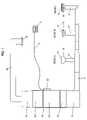
- FIG. 1shows a conventional residential forced-air HVAC system.
- FIG. 2shows the retrofit zone control system as retrofitted into the HVAC system.
- FIG. 3shows an inflatable air bladder which is used as an airflow control device in the retrofit zone control system.
- FIG. 4shows installation of the air bladder into a duct of the HVAC system.
- FIG. 5shows installation of the valve manifold into a plenum of the HVAC system.
- FIG. 6shows installation of the pneumatic control tubes into the ductwork of the HVAC system.
- FIG. 1is a block diagram of a typical forced air system.
- the existing central HVAC unit 10is typically comprised of a return air plenum 11 , a blower 12 , a furnace 13 , an optional heat exchanger for air conditioning 14 , and a conditioned air plenum 15 .
- the configuration shownis called “down flow” because the air flows down.
- Other possible configurationsinclude “up flow” and “horizontal flow”.
- a network of air duct trunks 16 and air duct branches 17connect from the conditioned air plenum to each air vent 18 in room A, room B, and room C. Each air vent is covered by an air grill 31 .
- the inventionis designed for larger houses with many rooms and at least one air vent in each room.
- the conditioned air forced into each roomis typically returned to the central HVAC unit through one or more common return air vents 19 located in central areas. Air flows through the air return duct 20 into the return plenum.
- the existing thermostat 21is connected by a multi-conductor cable 73 to the existing HVAC controller 22 that switches power to the blower, furnace and air conditioner.
- the existing thermostatcommands the blower and furnace or blower and air conditioner to provide conditioned air to cause the temperature at thermostat to move toward the temperature set at the existing thermostat.
- FIG. 1is only representative of many possible configurations of forced air HVAC systems found in existing houses.
- the air conditionercan be replaced by a heat pump that can provide both heating and cooling, eliminating the furnace.
- a heat pumpis used in combination with a furnace.
- the present inventioncan accommodate the different configurations found in most existing houses.
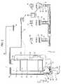
- FIG. 2is a block diagram of the present invention installed in an existing forced air HVAC system as shown in FIG. 1 .
- the airflow through each ventis controlled by a substantially airtight bladder 30 mounted behind the air grill 31 covering the air vent 18 .
- the bladderis, ideally, either fully inflated or fully deflated while the blower 12 is forcing air through the air duct 17 .
- a small air tube 32( ⁇ 0.25′′ OD) is pulled through the existing air ducts to connect each bladder to one air valve of a plurality of servo controlled air valves 40 .
- the air valvesare mounted on the side of the conditioned air plenum 15 .
- a small air pump in air pump enclosure 50provides a source of low-pressure ( ⁇ 1 psi) compressed air and vacuum at a rate of e.g. ⁇ 1.5 cubic feet per minute.
- the pressure air tube 51connects the pressurized air to the air valves.
- the vacuum air tube 52connects the vacuum to the air valves.
- the air pump enclosurealso contains a 5V power supply and control circuit for the air pump.
- the AC power cord 54connects the system to 110V AC power.
- the power and control cable 55connect the 5V power supply to the control processor and servo controlled air valves and connect the control processor 60 to the circuit that controls the air pump.
- the control processorcontrols the air valve servos to set each air valve to one of two positions. The first position connects the compressed air to the air tube so that the bladder inflates. The second position connects the vacuum to the air tube so that the bladder deflates.
- thermometer 70is placed in each room in the house. All thermometers transmit, on a shared radio frequency of 433 MHz, packets of digital information that encode 32-bit digital messages.
- a digital messageincludes a unique thermometer identification number, the temperature, and command data. Two or more thermometers can transmit at the same time, causing errors in the data. To detect errors, the 32-bit digital message is encoded twice in the packet.
- the radio receiver 71decodes the messages from all the thermometers, discards packets that have errors, and generates messages that are communicated by serial data link 72 to the control processor. The radio receiver can be located away from the shielding effects of the HVAC equipment if necessary, to ensure reception from all thermometers.
- the control processoris connected to the existing HVAC controller 22 by the existing HVAC controller connection 74 .
- the control processor interface circuituses the same signals as the existing thermostat 21 to control the HVAC equipment.
- the control processorcontrols the HVAC equipment and the airflow to each room according to the temperature reported for each room and according to an independent temperature schedule for each room.
- the temperature schedulesspecify a heat-when-below-temperature and a cool-when-above-temperature for each minute of a 24-hour day. A different temperature schedule can be specified for each day for each room.
- a graphical display screen 95 with a touch sensitive surfacereplaces the original thermostat.
- the wires 73 originally used to connect the thermostat to the HVAC equipmentare used to connect the display screen to the control processor.
- the occupantscan view and specify temperature schedules using the display screen and the touch sensitive surface. Energy use data, maintenance requirements, and other aspects of the system can be viewed and controlled through the display screen.
- the present inventioncan set the bladders so that all of the airflow goes to a single air vent, thereby conditioning the air in a single room. This could cause excessive air velocity and noise at the air vent and possibly damage the HVAC equipment.
- Thisis solved by connecting a bypass air duct 90 between the conditioned air plenum 15 and the return air plenum 11 .
- a bladder 91is installed in the bypass 90 and its air tube is connected to an air valve 40 so that the control processor can enable or disable the bypass.
- the bypassprovides a path for the excess airflow and storage for conditioned air.
- the control processoris interfaced to a temperature sensor 61 located inside the conditioned air plenum.
- the control processormonitors the conditioned air temperature to ensure that the temperature in the plenum does not go above a preset temperature when heating or below a preset temperature when cooling, and ensures that the blower continues to run until all of the heating or cooling has been transferred to the rooms. This is important when bypass is used and only a portion of the heating or cooling capacity is needed, so the furnace or air conditioner is turned only for a short time. Some existing HVAC equipment has two or more heating or cooling speeds or capacities. When present, the control processor controls the speed control and selects the speed based on the number of air vents open. This capability can eliminate the need for the bypass.
- a pressure sensor 62is mounted inside the conditioned air plenum and interfaced to the control processor.
- the plenum pressure as a function of different bladder settingsis used to deduce the airflow capacity of each air vent in the system and to predict the plenum pressure for any combination of air valve settings.
- the airflow to each room and the time spent heating or cooling each roomis use to provide a relative measure of the energy used to condition each room. This information is reported to the house occupants via the graphical display screen 95 .
- FIG. 3is a diagram showing the construction of the bladders 30 used as airflow control devices.
- the bladdersare constructed of flexible thin plastic or fabric coated with an airtight flexible sealer. The material is approved by UL or another listing agency for use in plenums.
- the bladders for controlling airflow in round air ductsare cylinders made by seaming together two circular shapes 301 and a rectangular shape 302 . Depending on the material, the airtight seams are heat sealed or glued. The material is only slightly elastic so the inflated size is determined by the dimensions of these shapes.
- An air tube connector 310is sealed to the rectangular shape 302 .
- the air tube connectoris molded from flexible plastic approved for use in plenums.
- FIG. 3Ashows more detail of the air tube connector, which has an air tube socket 312 sized so that it tightly grips the outside of the air tube 32 .
- the air tube connectorprovides the air path from the air tube to the inside of the bladder.
- the air tube connectoris contoured to match the curvature of the round air duct and has a notch 311 to fit a mounting strap. This shape prevents conditioned air from leaking around the bladder when it is inflated.
- the inflated bladder 303is about 110% the diameter of the air duct and its height is about 75% of the diameter. When inflated in the duct, the cylinder wall is pressed firmly against the inside of the air duct, effectively blocking all airflow.
- the deflated bladder 304presents a small cross-section to airflow and restricts airflow by less than 10%.
- the standard round duct sizes connecting to air vents in residential installationsare 4′′, 6′′, and 8′′.
- Bypass 90can be 6′′, 8′′, or 10′′ in diameter. A total of only 4 different round duct bladder sizes are needed for residential installations.
- the bladders for controlling airflow in rectangular ductsare also cylinders made by seaming together two circular shapes 321 and a rectangular shape 322 .
- the cylinderis oriented so that the axis of the cylinder is parallel to the widest dimension of the duct.
- the height of the cylinderis about 110% of the wider dimension of the duct.
- the cylinder diameteris at least 110% of the narrower dimension of the duct, but can be as much as 200%.
- FIG. 3Bshows more detail of the air tube connector 330 , which is contoured for the flat surface of the rectangular duct and it has a notch 331 to fit a mounting strap and air tube socket 332 sized to fit the outside of the air tube 32 .
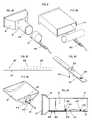
- FIG. 4shows several views of the method for mounting the bladder 30 in an air duct 17 at an air vent 18 covered by air grill 31 .
- the air tube 32is inserted into the air tube socket 312 in the air tube connector 310 sealed to the bladder 30 shown with the top portion cut away.
- Mounting clamp 402compresses the air tube socket around the air tube.
- FIG. 4Cis a plain view of the mounting strap, which is made from thin metal (18 gauge) and is approximately 1′′ by 12′′.
- Hole 407is used to secure the air tube to the mounting strap.
- One pair of holes 406are used to secure the mounting clamp 402 to the mounting strap.
- Two of the holes 408are used to secure the mounting strap to the inside of the air vent or air duct at the air vent.
- FIG. 4Dis a perspective drawing showing the mounting clamp 402 connecting to the mounting strap 401 .
- the mounting clampstraddles the air tube socket 312 (shown in FIG. 4E ) and two bladder clamp screws 405 pass through holes 406 in the mounting strap and screw into the mounting clamp.
- Several pairs of holes 406are provided so the bladder can be positioned for the most effective seal of the air duct.
- the screws 405are self-tapping with flat heads that match counter-sinks pressed into the holes 406 in the mounting strap.
- Tightening the bladder clamp screws 405cause the bladder clamp 402 to compress the air tube socket 312 firmly around the air tube 32 , securing the bladder to the mounting strap and ensuring an air tight seal between the air tube and the bladder.
- the screw headsare flat with the bottom surface of the mounting strap, and the mounting strap fits in the notch 311 of the air tube connector 310 so the mounting strap is flat with the air tube connector.
- FIG. 4Fis a cross-section view of the assembled bladder installed in an air duct 17 connecting to air vent 18 covered by air grill 31 .
- the air tube 32is secured to the mounting strap 401 by the air tube clamp 403 (also shown in FIG. 4D ) using a screw 409 and nut through hole 407 (shown in FIG. 4C ).
- the air tube clamptransfers any tension on the air tube to the mounting strap and prevents strain on the connection between the air tube and the bladder.
- the mounting clamp 402is connected to the mounting strap by two screws 405 and compresses the air tube socket 312 and secures the bladder 30 to the mounting strap.
- the mounting strapis secured to the inside of the air duct or air vent by two screws 404 through holes 408 (shown in FIG. 4C ).
- Some air ventsare constructed with in integrated section of air duct several inched long, which fits inside the connecting air duct 17 .
- the inflated bladdercan make contact with this extension of the air vent or it can make contact in the air duct when the extension is not part of the air vent.
- FIG. 4Ais an exploded perspective view of the assembled bladder 30 and mounting strap 401 fitting into the air duct 17 connected to air vent 18 .
- the inside of the air duct or air vent 410 where the bladder makes contactmust be a smooth surface. If sharp sheet metal edges or screws are present, they are cut or smoothed and covered with duct mastic or duct tape to form a smooth surface and contour.
- FIG. 4Bis an exploded perspective view of an assembled bladder and air tube secured to amounting strap 401 for mounting inside a rectangular air duct 411 .
- the air grillis removed and an air tube 32 is pulled from the air vent to the plenum 15 .
- the air tubeis secured to the mounting strap 401 and the proper size and shape bladder 30 is secured to the mounting strap.
- the inside surface 410 of the air vent or air ductis prepared by smoothing, cutting, or covering sharp edges and screws. In many cases, no preparation is required. This surface is chosen so it is close enough to the front of the air vent to provide convenient access for any surface preparation work.
- the mounting strapis inserted into the air vent and the mounting strap is bent and position so the inflated bladder meets the surface 410 .
- the mounting strapis then secured to the inside of the air vent by one or two sheet metal screws.
- the air grillis then reinstalled. After installation, the bladder is hidden by the air grill, and there are no visible signs of installation. The installation requires no other modification to the air duct, air vent, or air grill, and no other access to the air duct is required.
- FIG. 5is an exploded perspective view of the system components that are mounted at a central location, such as on the conditioned air plenum 15 .
- the control processor 60 and interface circuitsare built on a PCB (printed circuit board) 1700 approximately 5′′ ⁇ 5′′, which is mounted to the main enclosure base 1701 .
- the PCBincludes the terminals and sockets used to connect the control processor signals to the servo controlled air valves 40 , the power and control connection 55 , the temperature sensor, the pressure sensor, the radio receiver connection, the existing thermostat connection 73 , the existing HVAC controller connection 74 , the RS232 connection 1551 , and the remote connection 1550 .
- Side 1703 of the main enclosure base 1701has access cutouts and restraining cable clamps 1702 for the power and control connection, the radio connection, the existing thermostat connection, the existing HVAC controller connection, the RS232 connection 1551 , and the remote connection 1550 (when used).
- the main enclosure base 1701has a cutout sized and positioned to provide clearance for the valve header on the valve block and valve block.
- the servo controlled air valve 40is mounted to the main enclosure base 1701 .
- the main enclosure basealso has cutouts for the pressure and temperature sensors to access the inside of the plenum and for the link connection to pass from the plenum to its connector on the PCB 1700 .
- the PCBis mounted above the air valve blocks.
- Side 1703also has cutouts for the pressure air tube 51 and vacuum air tube 52 connected to the air-feed tee.
- the main enclosure top 1710fits to the base 1701 to form a complete enclosure. Vent slots 1711 in the main enclosure top provide ventilation. A cutout 1712 in the main enclosure top matches the location of switch 1405 on PCB 1700 so that when the main enclosure top is in position, the switch 1405 can be manually switched to either position.
- a hole 1720 approximately 8′′ ⁇ 8′′is cut in the side of the conditioned air plenum 15 .
- the holeprovides access for the process used to pull the air tubes 32 and to provide access when attaching the air tubes.
- the main enclosure base 1701is approximately 9′′ ⁇ 9′′.
- the pressure and temperature sensors and the air tube headersare arranged to fit inside the 8′′ ⁇ 8′′ hole cut 1720 in the side of the plenum.
- the main unitis attached to the plenum with sheet metal screws and sealant so as to cover and seal the hole 1720 in the side of the plenum.
- the present inventionis designed for easy installation in existing residential houses. Access is required only to the air vents and the central HVAC plenum. All required installation processes are known to those skilled in the art of HVAC installation with the exception of pulling the air tubes through the air ducts.
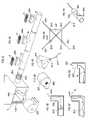
- the present inventionincludes a novel process for pulling the air tubes trough the air ducts. The description of the process refers to the views shown in FIG. 6 .
- the methodhas the following steps, which do not necessarily have to be performed in exactly the order listed:
- the access hole 1720is cut in the air plenum 15 .
- a high-speed installation blower 2801is connected by flexible duct 2802 to hole 1720 .
- a substantially airtight seal 2803is formed at the end of the flexible duct between the outside of the flexible duct and the inside of the plenum. This seal can be made using a thin foam rubber gasket. It is necessary to prevent airflow from the return air plenum. This can be accomplished by removing the air filter (not shown) which is typically housed within the plenum, covering it with plastic film, and reinstalling it.
- each return air ventcould be sealed, such as by the same method used to seal the output vents. Alternatively, since the return vent grills do not need to be removed, the vents could be sealed using plastic film and tape.
- FIG. 6Bis a reverse view of the installation blower 2801 and its input 2804 that is connected to the flexible duct 2802 .
- the duct systemshould be substantially airtight.
- Typical blowerscan generate a maximum vacuum of 0.5′′ to 1.0′′ inches H 2 O. The actual vacuum produced can be used as a measure of the leakage of the duct system. If the leakage is large, the vacuum will be much less than the blower can create, indicating the duct system should be repaired before completing the installation.
- FIG. 6CA perspective view of an inflated parachute 2810 is shown in FIG. 6C .
- FIG. 6Dillustrates the construction of the parachute.
- the parachuteis made from a sheet of high strength plastic film 2811 about 0.002 inch thick and 16′′ by 16′′.
- Two strong strings 2812approximately 6-feet long cross the plastic film and connect at the four corners 2813 .
- the four ends 2814are connected to a single long strong pull string 2815 .
- a high quality 200 lb test fishing lineis used for pull string 2815 .
- the parachute 2810is introduced into the air vent while the pull string 2815 is held under tension.
- the airflowinflates the parachute sealing its edges to the inside of the air duct. This creates a strong pull on the parachute and in turn the pull string.
- the parachuteis pulled through the air duct toward the blower 2801 in the conditioned air plenum 15 as the string 2815 is let out.
- parachuteIf the parachute snags, it can be freed by pulling the string back and forth. This temporarily collapses the parachute so that turbulence in the airflow helps find another path for the parachute.
- the air tube 32is connected to the air vent end of pull string 2815 .
- the parachute end of pull string 2815is used to pull the air tube through the air duct to the end of the disconnected flexible duct 2802 .
- the string and air tubemay be pulled in the opposite direction, from the plenum to the vent.
- the collapsed parachutemay be pulled with them back to the vent, for retrieval for use at a next vent.
- the connector described in co-pending application Ser. No. 10/249,196may optionally and advantageously be used in connecting the string to the air tube, and in pulling the string to draw the air tube through the ductwork.
- FIG. 6Hwhich is a detailed view of the end of the flexible air duct 2802 , the pull string 2815 is removed from the air tube.
- the air tubeis labeled (ref. no. 2822 ) to associate it with the particular air vent 2820 , passed through an air seal 2821 on the side of the flexible duct 2802 , and the flexible duct is reattached to the installation blower 2801 .
- the air tubecould be passed between the foam rubber which seals the end of the flexible duct to the duct trunk, and the inner surface of the duct trunk.
- the air tubeis cut from the supply spool, secured inside the room 2821 , and the air vent is resealed with the foam block 2800 .
- Process steps 5 through 13are repeated for each of the remaining air vents, in order of furthest to nearest to the plenum 15 or in any other suitable order.
- the air tubecould be directly pulled through by the parachute, without the intermediate steps of the parachute pulling a string and the string being used to pull the air tube.
- the blowercould be used to blow or suck a ball through the ductwork.
- the stringcould be attached to a “tumbleweed” or “porcupine” type of structure which has a large overall surface area made of smaller objects protruding from a central core, such as a rubber ball having a multitude of turkey feathers stuck into it at various angles.
- a wad of plastic bags or the likeis another alternative.
- the objectwill, ideally, exhibit (i) a large surface area for good wind resistance and thus good pulling force, (ii) sufficient flexibility to pass around the various corners and edges of the ductwork, (iii) the ability to adapt to the various diameters and shapes of ducts and trunks which it will encounter, (iv) a resistance to snagging, and (v) low cost.
- the preferred installation methodis to route the air tubes into the plenum
- an installercould, alternatively, cut a hole through the primary trunk leaving the plenum, route the air tubes out this hole, seal the hole around the air tubes, and install the valve system and other central components at this location, rather than at the plenum.
- Thisstill avoids any need for accessing the ducts, vents, and intermediate trunks, which will typically be more difficult to access than the primary trunk.
- this less optimal installationmay be preferred, such as if the plenum itself is hard to access, or if there are security concerns which require that the home automation controller and the valve system be located e.g. under the house rather than in the garage with the furnace and plenum.
- the installermay also perform diagnostic analyses on the HVAC system, before removing the installation equipment.
- blowersprovide different air pressure at different rates of airflow. The less backpressure or obstruction that is placed on the blower's output, the higher the airflow and the lower the pressure will be; conversely, the more the output is obstructed, the lower the airflow and the higher the pressure will be.
- the installerturns on the blower and measures the pressure inside the duct trunk network (such as with a pressure gauge placed inside the duct trunk or extending through the flexible duct opening 2821 ).
- a pressure-versus-airflow chartideally one customized for that particular blower unit, will tell the installer how much airflow is escaping the system.
- the installermay take into account the number of vents (which may not have absolutely airtight seals created by their foam blocks or other temporary sealing mechanisms), to determine an amount of leakage.
- leakagemay be caused by, for example, ducts which have come loose from their trunks, duct or trunk joints which have come loose or whose duct tape has failed, and so forth.
- the installermay measure airflow through each individual vent in the same manner.
- the installerremoves the foam or other seal from the vent, operates the blower, measures the pressure, and calculates the airflow.
- the installercan perform this operation for each successive vent. If any vent has an airflow calculation (or, in other words, pressure measurement) which is out of range with respect to the others, the installer may determine that there is an obstruction or other problem with that vent's duct, and may take appropriate corrective measures. By taking measurements with different sets of two or more vents unblocked at a time, the installer may deduce other problems, such as too many ducts run from a common trunk.
- the system of this inventionmay be installed in old, existing residential or commercial buildings, or it may be installed in newly constructed buildings.
- the diagnostic analysis capabilities of this inventionmay be used to validate the quality of the work previously done by the installers of the basic HVAC system, to find and fix problems before construction continues (such as covering up ductwork by installing drywall), before signing off on or paying for the HVAC installation, and/or before the closing of the real estate transaction.
- the retrofit system of this inventioncould even be used to perform such analysis even if the retrofit system is not being permanently installed; it could be temporarily installed simply as a quality control means for the basic HVAC system.
- Similar analysesmay be performed by the home automation system itself, long after installation, by using the inflatable bladders to block the vents and by using the plenum pressure sensor 62 to measure the pressure.
- the controllercould take a set of measurements, such as: pressure with all vents closed, pressure with each individual vent open by itself, pressure with each combination of two vents open, and so forth. The controller could save this set of measurements as a baseline, and then periodically re-run the diagnostic test set to see if any of the measurements has significantly diverged from its baseline, indicating that something has changed in the HVAC system, such as a duct coming loose from its trunk, or a child having thrown a stuffed animal down a duct, and the like.
- the inventionhas been described with reference to a conventional HVAC system having common return air intake vents, it may also be used in a system in which some or all of the rooms have their own, individual return air vents.
- the installationmay include installing air tubes and inflatable bladders into the return air vents or ducts, and the zone climate controller may individually operate the return air vents, to provide still greater performance improvements. For example, if each room has both a conditioned air vent and a return air vent, the controller can, with complete specificity, move air from one room to another room.
Landscapes
- Engineering & Computer Science (AREA)
- Chemical & Material Sciences (AREA)
- Combustion & Propulsion (AREA)
- Mechanical Engineering (AREA)
- General Engineering & Computer Science (AREA)
- Air Conditioning Control Device (AREA)
- Duct Arrangements (AREA)
- Valve Housings (AREA)
- Fluid-Pressure Circuits (AREA)
Abstract
Description
Claims (18)
Priority Applications (1)
| Application Number | Priority Date | Filing Date | Title |
|---|---|---|---|
| US10/717,053US7062830B2 (en) | 2003-03-21 | 2003-11-18 | Installation of a retrofit HVAC zone control system |
Applications Claiming Priority (2)
| Application Number | Priority Date | Filing Date | Title |
|---|---|---|---|
| US10/249,198US6983889B2 (en) | 2003-03-21 | 2003-03-21 | Forced-air zone climate control system for existing residential houses |
| US10/717,053US7062830B2 (en) | 2003-03-21 | 2003-11-18 | Installation of a retrofit HVAC zone control system |
Related Parent Applications (1)
| Application Number | Title | Priority Date | Filing Date |
|---|---|---|---|
| US10/249,198Continuation-In-PartUS6983889B2 (en) | 2003-03-21 | 2003-03-21 | Forced-air zone climate control system for existing residential houses |
Publications (2)
| Publication Number | Publication Date |
|---|---|
| US20040181921A1 US20040181921A1 (en) | 2004-09-23 |
| US7062830B2true US7062830B2 (en) | 2006-06-20 |
Family
ID=32987020
Family Applications (6)
| Application Number | Title | Priority Date | Filing Date |
|---|---|---|---|
| US10/249,198Expired - LifetimeUS6983889B2 (en) | 2003-03-21 | 2003-03-21 | Forced-air zone climate control system for existing residential houses |
| US10/717,053Expired - LifetimeUS7062830B2 (en) | 2003-03-21 | 2003-11-18 | Installation of a retrofit HVAC zone control system |
| US10/750,467Expired - LifetimeUS7207496B2 (en) | 2003-03-21 | 2003-12-31 | Vent-blocking inflatable bladder for a retrofit HVAC zone control system |
| US10/750,709Expired - LifetimeUS7162884B2 (en) | 2003-03-21 | 2004-01-02 | Valve manifold for HVAC zone control |
| US10/873,921Expired - LifetimeUS7188779B2 (en) | 2003-03-21 | 2004-06-22 | Zone climate control |
| US11/028,845Expired - LifetimeUS6997390B2 (en) | 2003-03-21 | 2005-01-03 | Retrofit HVAC zone climate control system |
Family Applications Before (1)
| Application Number | Title | Priority Date | Filing Date |
|---|---|---|---|
| US10/249,198Expired - LifetimeUS6983889B2 (en) | 2003-03-21 | 2003-03-21 | Forced-air zone climate control system for existing residential houses |
Family Applications After (4)
| Application Number | Title | Priority Date | Filing Date |
|---|---|---|---|
| US10/750,467Expired - LifetimeUS7207496B2 (en) | 2003-03-21 | 2003-12-31 | Vent-blocking inflatable bladder for a retrofit HVAC zone control system |
| US10/750,709Expired - LifetimeUS7162884B2 (en) | 2003-03-21 | 2004-01-02 | Valve manifold for HVAC zone control |
| US10/873,921Expired - LifetimeUS7188779B2 (en) | 2003-03-21 | 2004-06-22 | Zone climate control |
| US11/028,845Expired - LifetimeUS6997390B2 (en) | 2003-03-21 | 2005-01-03 | Retrofit HVAC zone climate control system |
Country Status (2)
| Country | Link |
|---|---|
| US (6) | US6983889B2 (en) |
| WO (1) | WO2004085180A2 (en) |
Cited By (34)
| Publication number | Priority date | Publication date | Assignee | Title |
|---|---|---|---|---|
| US20070057075A1 (en)* | 2005-09-14 | 2007-03-15 | Arzel Zoning Technology, Inc. | System and method for heat pump oriented zone control |
| US20070063059A1 (en)* | 2005-09-14 | 2007-03-22 | Arzel Zoning Technology, Inc. | System and method for heat pump oriented zone control |
| US20070173192A1 (en)* | 2006-01-20 | 2007-07-26 | Arzel Technology, Inc. | Small duct high velocity damper assembly |
| US20080113609A1 (en)* | 2006-11-14 | 2008-05-15 | Robertshaw Controls Company | Combined Supply and Exhaust Apparatus |
| US20100081357A1 (en)* | 2008-09-29 | 2010-04-01 | Harold Gene Alles | Remote controlled vehicle for threading a string through HVAC ducts |
| US20100102135A1 (en)* | 2008-10-23 | 2010-04-29 | Harold Gene Alles | Method for Controlling a Multi-Zone Forced Air HVAC System To Reduce Energy Use |
| US20100314458A1 (en)* | 2005-09-14 | 2010-12-16 | Arzel Zoning Technology, Inc. | System and method for heat pump oriented zone control |
| US20110062246A1 (en)* | 2009-09-15 | 2011-03-17 | Asghar Khalafi | System and method for creating multizones from a single zone heating system |
| US20110250833A1 (en)* | 2010-04-09 | 2011-10-13 | Richard Corey Breed | Air duct blocking device for obstructing airflow through portions of an air duct system |
| US20140261725A1 (en)* | 2013-03-12 | 2014-09-18 | John C. Karamanos | Piping stick systems and methods |
| US8964338B2 (en) | 2012-01-11 | 2015-02-24 | Emerson Climate Technologies, Inc. | System and method for compressor motor protection |
| US8974573B2 (en) | 2004-08-11 | 2015-03-10 | Emerson Climate Technologies, Inc. | Method and apparatus for monitoring a refrigeration-cycle system |
| US9121407B2 (en) | 2004-04-27 | 2015-09-01 | Emerson Climate Technologies, Inc. | Compressor diagnostic and protection system and method |
| US9140728B2 (en) | 2007-11-02 | 2015-09-22 | Emerson Climate Technologies, Inc. | Compressor sensor module |
| US9285802B2 (en) | 2011-02-28 | 2016-03-15 | Emerson Electric Co. | Residential solutions HVAC monitoring and diagnosis |
| US9310439B2 (en) | 2012-09-25 | 2016-04-12 | Emerson Climate Technologies, Inc. | Compressor having a control and diagnostic module |
| US9310094B2 (en) | 2007-07-30 | 2016-04-12 | Emerson Climate Technologies, Inc. | Portable method and apparatus for monitoring refrigerant-cycle systems |
| US9551504B2 (en) | 2013-03-15 | 2017-01-24 | Emerson Electric Co. | HVAC system remote monitoring and diagnosis |
| US9638433B2 (en) | 2012-09-28 | 2017-05-02 | Trane International Inc. | System and method for managing HVAC excess air condition |
| US9638436B2 (en) | 2013-03-15 | 2017-05-02 | Emerson Electric Co. | HVAC system remote monitoring and diagnosis |
| US9765979B2 (en) | 2013-04-05 | 2017-09-19 | Emerson Climate Technologies, Inc. | Heat-pump system with refrigerant charge diagnostics |
| US9803902B2 (en) | 2013-03-15 | 2017-10-31 | Emerson Climate Technologies, Inc. | System for refrigerant charge verification using two condenser coil temperatures |
| US9823632B2 (en) | 2006-09-07 | 2017-11-21 | Emerson Climate Technologies, Inc. | Compressor data module |
| US9885507B2 (en) | 2006-07-19 | 2018-02-06 | Emerson Climate Technologies, Inc. | Protection and diagnostic module for a refrigeration system |
| US10184678B2 (en) | 2013-09-06 | 2019-01-22 | Carrier Corporation | System and method for measuring duct leakage in a HVAC system |
| US10190794B1 (en) | 2014-10-13 | 2019-01-29 | Arzel Zoning Technology, Inc. | System and apparatus for wireless environmental zone control |
| CN110030636A (en)* | 2019-04-09 | 2019-07-19 | 深圳市大元通机电设备有限公司 | A kind of Protection control system and working method of air conditioner |
| US10447201B1 (en)* | 2019-01-09 | 2019-10-15 | Kuwait Institute For Scientific Research | Device and method for measuring effect of soiling on photovoltaic device |
| US10473358B2 (en) | 2010-04-09 | 2019-11-12 | Richard Corey Breed | Air duct sealing system for obstructing or directing airflow through portions of an air duct system |
| US10476431B1 (en)* | 2019-01-09 | 2019-11-12 | Kuwait Institute For Scientific Research | Device and method for measuring effect of soiling on photovoltaic device |
| US10539605B2 (en)* | 2015-02-16 | 2020-01-21 | Continental Automotive Systems, Inc. | Negative battery main contactor status determination |
| US10948215B2 (en) | 2014-10-13 | 2021-03-16 | Arzel Zoning Technology, Inc. | System and method for wireless environmental zone control |
| US11480358B2 (en) | 2021-02-25 | 2022-10-25 | Synapse Wireless, Inc. | Machine learning systems for modeling and balancing the activity of air quality devices in industrial applications |
| US11713895B2 (en) | 2019-01-14 | 2023-08-01 | Research Products Corporation | Multi-zone environmental control system |
Families Citing this family (361)
| Publication number | Priority date | Publication date | Assignee | Title |
|---|---|---|---|---|
| AUPR215200A0 (en)* | 2000-12-19 | 2001-01-25 | Guignard, Paul A. | Generic knowledge agents |
| US6892546B2 (en) | 2001-05-03 | 2005-05-17 | Emerson Retail Services, Inc. | System for remote refrigeration monitoring and diagnostics |
| US6668240B2 (en) | 2001-05-03 | 2003-12-23 | Emerson Retail Services Inc. | Food quality and safety model for refrigerated food |
| US6826729B1 (en)* | 2001-06-29 | 2004-11-30 | Microsoft Corporation | Gallery user interface controls |
| US11841159B2 (en) | 2002-03-06 | 2023-12-12 | John Chris Karamanos | Embedded heat exchanger with support mechanism |
| US6889173B2 (en)* | 2002-10-31 | 2005-05-03 | Emerson Retail Services Inc. | System for monitoring optimal equipment operating parameters |
| US8463441B2 (en) | 2002-12-09 | 2013-06-11 | Hudson Technologies, Inc. | Method and apparatus for optimizing refrigeration systems |
| US6983889B2 (en)* | 2003-03-21 | 2006-01-10 | Home Comfort Zones, Inc. | Forced-air zone climate control system for existing residential houses |
| US7302642B2 (en)* | 2003-06-03 | 2007-11-27 | Tim Simon, Inc. | Thermostat with touch-screen display |
| US9715678B2 (en)* | 2003-06-26 | 2017-07-25 | Microsoft Technology Licensing, Llc | Side-by-side shared calendars |
| US8799808B2 (en)* | 2003-07-01 | 2014-08-05 | Microsoft Corporation | Adaptive multi-line view user interface |
| US20050005249A1 (en)* | 2003-07-01 | 2005-01-06 | Microsoft Corporation | Combined content selection and display user interface |
| US7716593B2 (en)* | 2003-07-01 | 2010-05-11 | Microsoft Corporation | Conversation grouping of electronic mail records |
| US7707255B2 (en)* | 2003-07-01 | 2010-04-27 | Microsoft Corporation | Automatic grouping of electronic mail |
| US7222800B2 (en)* | 2003-08-18 | 2007-05-29 | Honeywell International Inc. | Controller customization management system |
| US7055759B2 (en)* | 2003-08-18 | 2006-06-06 | Honeywell International Inc. | PDA configuration of thermostats |
| US20050048960A1 (en)* | 2003-09-03 | 2005-03-03 | Sharp Kabushiki Kaisha | Information processing device, control device, communication device, communication equipment, electronic device, information processing system, power management method, power management program, and recording medium |
| US10437964B2 (en) | 2003-10-24 | 2019-10-08 | Microsoft Technology Licensing, Llc | Programming interface for licensing |
| US7114554B2 (en)* | 2003-12-01 | 2006-10-03 | Honeywell International Inc. | Controller interface with multiple day programming |
| US7706923B2 (en)* | 2003-12-02 | 2010-04-27 | Honeywell International Inc. | Controller interface with separate schedule review mode |
| US10705549B2 (en)* | 2003-12-02 | 2020-07-07 | Ademco Inc. | Controller interface with menu schedule override |
| US7188002B2 (en)* | 2004-01-08 | 2007-03-06 | Maple Chase Company | Appliance diagnostic display apparatus and network incorporating same |
| US8255828B2 (en) | 2004-08-16 | 2012-08-28 | Microsoft Corporation | Command user interface for displaying selectable software functionality controls |
| US8117542B2 (en) | 2004-08-16 | 2012-02-14 | Microsoft Corporation | User interface for displaying selectable software functionality controls that are contextually relevant to a selected object |
| US8146016B2 (en) | 2004-08-16 | 2012-03-27 | Microsoft Corporation | User interface for displaying a gallery of formatting options applicable to a selected object |
| US7703036B2 (en)* | 2004-08-16 | 2010-04-20 | Microsoft Corporation | User interface for displaying selectable software functionality controls that are relevant to a selected object |
| US9015621B2 (en)* | 2004-08-16 | 2015-04-21 | Microsoft Technology Licensing, Llc | Command user interface for displaying multiple sections of software functionality controls |
| US7895531B2 (en)* | 2004-08-16 | 2011-02-22 | Microsoft Corporation | Floating command object |
| US7747966B2 (en)* | 2004-09-30 | 2010-06-29 | Microsoft Corporation | User interface for providing task management and calendar information |
| US8033479B2 (en) | 2004-10-06 | 2011-10-11 | Lawrence Kates | Electronically-controlled register vent for zone heating and cooling |
| US7156316B2 (en)* | 2004-10-06 | 2007-01-02 | Lawrence Kates | Zone thermostat for zone heating and cooling |
| US7163156B2 (en)* | 2004-10-06 | 2007-01-16 | Lawrence Kates | System and method for zone heating and cooling |
| EP1800438A1 (en)* | 2004-10-14 | 2007-06-27 | Lagotek Corporation | Distributed wireless home and commercial electrical automation systems |
| US8348732B2 (en)* | 2004-11-12 | 2013-01-08 | Adaptive-Ac, Inc. | Airflow control system |
| US7347774B2 (en)* | 2004-11-12 | 2008-03-25 | Peter S. Aronstam | Remote autonomous intelligent air flow control system and network |
| US7537171B2 (en)* | 2004-11-17 | 2009-05-26 | Emerson Electric Co. | Thermostat control system providing power saving transmissions |
| US7174239B2 (en)* | 2004-11-19 | 2007-02-06 | Emerson Electric Co. | Retrieving diagnostic information from an HVAC component |
| KR20060072525A (en)* | 2004-12-23 | 2006-06-28 | 엘지전자 주식회사 | Air Conditioning Offering Wellness Index |
| US7802618B2 (en)* | 2005-01-19 | 2010-09-28 | Tim Simon, Inc. | Thermostat operation method and apparatus |
| US20060196953A1 (en)* | 2005-01-19 | 2006-09-07 | Tim Simon, Inc. | Multiple thermostat installation |
| US7647895B2 (en)* | 2005-02-07 | 2010-01-19 | Emerson Electric Co. | Systems and methods for controlling a water heater |
| US20080003530A1 (en)* | 2006-06-30 | 2008-01-03 | Emerson Electric Co. | Communicating control for fuel fired heating appliance |
| US7367199B2 (en)* | 2005-02-11 | 2008-05-06 | Cohand Technology Co., Ltd. | Method for automatically balancing air conditioning outdoor heat exchange |
| US20060183419A1 (en)* | 2005-02-17 | 2006-08-17 | York International Corporation | Air handling unit mixing method and system |
| ATE553422T1 (en)* | 2005-02-21 | 2012-04-15 | Computer Process Controls Inc | CONTROL AND MONITORING SYSTEM FOR COMPANIES |
| US7584897B2 (en)* | 2005-03-31 | 2009-09-08 | Honeywell International Inc. | Controller system user interface |
| US7886290B2 (en)* | 2005-06-16 | 2011-02-08 | Microsoft Corporation | Cross version and cross product user interface |
| US7364093B2 (en)* | 2005-06-20 | 2008-04-29 | Emerson Electric Co. | Thermostat having default curtailment temperature settings |
| US7677464B1 (en)* | 2005-08-22 | 2010-03-16 | Donohue Kieran L | Specialized space control and monitoring system |
| US8239882B2 (en)* | 2005-08-30 | 2012-08-07 | Microsoft Corporation | Markup based extensibility for user interfaces |
| US8689137B2 (en)* | 2005-09-07 | 2014-04-01 | Microsoft Corporation | Command user interface for displaying selectable functionality controls in a database application |
| US9542667B2 (en)* | 2005-09-09 | 2017-01-10 | Microsoft Technology Licensing, Llc | Navigating messages within a thread |
| US8627222B2 (en) | 2005-09-12 | 2014-01-07 | Microsoft Corporation | Expanded search and find user interface |
| US7739259B2 (en) | 2005-09-12 | 2010-06-15 | Microsoft Corporation | Integrated search and find user interface |
| US7752854B2 (en)* | 2005-10-21 | 2010-07-13 | Emerson Retail Services, Inc. | Monitoring a condenser in a refrigeration system |
| US7752853B2 (en)* | 2005-10-21 | 2010-07-13 | Emerson Retail Services, Inc. | Monitoring refrigerant in a refrigeration system |
| US8232860B2 (en) | 2005-10-21 | 2012-07-31 | Honeywell International Inc. | RFID reader for facility access control and authorization |
| US7813829B2 (en)* | 2005-11-30 | 2010-10-12 | Toray Industries, Inc. | Sheet manufacturing method and sheet manufacturing device |
| US20070171196A1 (en)* | 2006-01-23 | 2007-07-26 | Thomas Robert Pfingsten | Controller user interface and method |
| US20070204921A1 (en)* | 2006-03-01 | 2007-09-06 | Home Comfort Zones, Inc. | Valve manifold |
| EP1852660A1 (en)* | 2006-05-03 | 2007-11-07 | Roth Werke GmbH | Process and device for heating and/or cooling a building |
| US7437941B1 (en)* | 2006-05-08 | 2008-10-21 | Diversitech Corporation | Heating and air conditioning service gauge |
| US7685882B1 (en) | 2006-05-08 | 2010-03-30 | Diversitech Corporation | Heating and air conditioning service gauge |
| EP1857363A1 (en) | 2006-05-19 | 2007-11-21 | Lebrun Nimy | Temperature regulating device |
| US20070277542A1 (en)* | 2006-05-30 | 2007-12-06 | Ranco Incorporated Of Delaware | Auto-balancing damper control |
| US8605090B2 (en) | 2006-06-01 | 2013-12-10 | Microsoft Corporation | Modifying and formatting a chart using pictorially provided chart elements |
| US9727989B2 (en) | 2006-06-01 | 2017-08-08 | Microsoft Technology Licensing, Llc | Modifying and formatting a chart using pictorially provided chart elements |
| US7738972B2 (en)* | 2006-06-29 | 2010-06-15 | Honeywell International Inc. | Modular shared-memory resource stage driver system for flexible resource linking in an energy conversion system |
| US7653459B2 (en)* | 2006-06-29 | 2010-01-26 | Honeywell International Inc. | VAV flow velocity calibration and balancing system |
| US8112162B2 (en)* | 2006-06-29 | 2012-02-07 | Honeywell International Inc. | System level function block engine |
| US8418128B2 (en)* | 2006-06-29 | 2013-04-09 | Honeywell International Inc. | Graphical language compiler system |
| US9726392B2 (en)* | 2006-06-29 | 2017-08-08 | Honeywell International Inc. | Generic user interface system |
| US7826929B2 (en)* | 2006-06-29 | 2010-11-02 | Honeywell International Inc. | Low cost programmable HVAC controller having limited memory resources |
| US20080006708A1 (en)* | 2006-07-10 | 2008-01-10 | Kantengri Design, Ltd. | Move-a-thermostat system |
| JP2008023512A (en)* | 2006-07-21 | 2008-02-07 | Satako:Kk | Stone kiln with smoke removal deodorizer |
| US20080033599A1 (en)* | 2006-08-02 | 2008-02-07 | Rouzbeh Aminpour | Method and system for controlling heating ventilation and air conditioning (HVAC) units |
| US7693809B2 (en)* | 2006-09-12 | 2010-04-06 | Home Comfort Zones, Inc. | Control interface for environment control systems |
| USD581947S1 (en)* | 2006-10-12 | 2008-12-02 | Smc Corporation | Valve manifold |
| USD581946S1 (en)* | 2006-10-12 | 2008-12-02 | Smc Corporation | Valve manifold |
| USD581948S1 (en)* | 2006-10-12 | 2008-12-02 | Smc Corporation | Valve manifold |
| US20080096482A1 (en)* | 2006-10-18 | 2008-04-24 | Ola Wettergren | Fan controller |
| US7571865B2 (en)* | 2006-10-31 | 2009-08-11 | Tonerhead, Inc. | Wireless temperature control system |
| JP4140649B2 (en)* | 2006-11-28 | 2008-08-27 | ダイキン工業株式会社 | Air conditioning system |
| US7693583B2 (en)* | 2006-11-30 | 2010-04-06 | Honeywell International Inc. | HVAC zone control panel with constant function buttons |
| US20080128523A1 (en)* | 2006-11-30 | 2008-06-05 | Honeywell International Inc. | Hvac zone control panel |
| US7913180B2 (en)* | 2006-11-30 | 2011-03-22 | Honeywell International Inc. | HVAC zone control panel with mode navigation |
| US7558648B2 (en)* | 2006-11-30 | 2009-07-07 | Honeywell International Inc. | HVAC zone control panel with zone configuration |
| US7904830B2 (en) | 2006-11-30 | 2011-03-08 | Honeywell International Inc. | HVAC zone control panel |
| US7693591B2 (en)* | 2006-11-30 | 2010-04-06 | Honeywell International Inc. | HVAC zone control panel with checkout utility |
| CA2570613C (en)* | 2006-12-07 | 2014-01-14 | The Mattamy Corporation | Insulating method and ducting configuration |
| US8290629B1 (en)* | 2006-12-18 | 2012-10-16 | Sprint Communications Company L.P. | Airflow management |
| TWM327001U (en)* | 2006-12-28 | 2008-02-11 | Pin Life Co Ltd | Apparatus of creating atmosphere |
| US7957839B2 (en) | 2006-12-29 | 2011-06-07 | Honeywell International Inc. | HVAC zone controller |
| KR20090104063A (en)* | 2007-01-17 | 2009-10-05 | 다이킨 고교 가부시키가이샤 | Air conditioning control system |
| US8020777B2 (en) | 2007-01-29 | 2011-09-20 | Lawrence Kates | System and method for budgeted zone heating and cooling |
| US20080179053A1 (en)* | 2007-01-29 | 2008-07-31 | Lawrence Kates | System and method for zone thermostat budgeting |
| US20080188174A1 (en)* | 2007-02-01 | 2008-08-07 | Rouzbeh Aminpour | Power system for a building structure |
| US8042784B2 (en)* | 2007-02-27 | 2011-10-25 | Pinnacle Products International, Inc. | Mounting frame for portable equipment |
| US7766246B2 (en)* | 2007-03-15 | 2010-08-03 | Honeywell International Inc. | Variable speed blower control in an HVAC system having a plurality of zones |
| US7819331B2 (en)* | 2007-04-13 | 2010-10-26 | Honeywell International Inc. | HVAC staging control |
| CN100416172C (en)* | 2007-04-28 | 2008-09-03 | 珠海格力电器股份有限公司 | The method of controlling the air conditioner to run according to the custom curve |
| US20080295030A1 (en)* | 2007-05-22 | 2008-11-27 | Honeywell International Inc. | User interface for special purpose controller |
| WO2008144804A1 (en)* | 2007-05-28 | 2008-12-04 | Honeywell International Inc | Systems and methods for commissioning access control devices |
| EP2150901B1 (en)* | 2007-05-28 | 2015-09-16 | Honeywell International Inc. | Systems and methods for configuring access control devices |
| JP5090522B2 (en)* | 2007-05-29 | 2012-12-05 | ユーティーシー パワー コーポレイション | Rankine cycle power plant heat source control |
| US8762880B2 (en) | 2007-06-29 | 2014-06-24 | Microsoft Corporation | Exposing non-authoring features through document status information in an out-space user interface |
| US8484578B2 (en) | 2007-06-29 | 2013-07-09 | Microsoft Corporation | Communication between a document editor in-space user interface and a document editor out-space user interface |
| US8201103B2 (en)* | 2007-06-29 | 2012-06-12 | Microsoft Corporation | Accessing an out-space user interface for a document editor program |
| US8036816B2 (en) | 2007-07-13 | 2011-10-11 | Cummins, Inc. | Totally integrated temperature sensor |
| US7739921B1 (en)* | 2007-08-21 | 2010-06-22 | The United States Of America As Represented By The Secretary Of The Navy | Parameter measurement/control for fluid distribution systems |
| US20090065595A1 (en)* | 2007-09-12 | 2009-03-12 | Lawrence Kates | System and method for zone heating and cooling using controllable supply and return vents |
| US8160752B2 (en) | 2008-09-30 | 2012-04-17 | Zome Networks, Inc. | Managing energy usage |
| US8086352B1 (en) | 2007-10-04 | 2011-12-27 | Scott Elliott | Predictive efficient residential energy controls |
| US8650306B2 (en)* | 2007-10-24 | 2014-02-11 | Honeywell International Inc. | Interoperable network programmable controller generation system |
| US9395771B1 (en)* | 2007-10-26 | 2016-07-19 | Pce, Inc. | Plenum pressure control system |
| US9151510B2 (en)* | 2007-11-30 | 2015-10-06 | Honeywell International Inc. | Display for HVAC systems in remote control units |
| WO2009089160A2 (en)* | 2008-01-03 | 2009-07-16 | Idle Free Systems, Llc | Charge circuit systems and methods of using the same |
| TW200930955A (en)* | 2008-01-15 | 2009-07-16 | Chunghwa Telecom Co Ltd | Management system for scheduling air condition apparatus |
| US20110071929A1 (en)* | 2008-01-30 | 2011-03-24 | Honeywell International Inc. | Systems and methods for managing building services |
| US7940188B2 (en)* | 2008-02-07 | 2011-05-10 | Veltek Associates, Inc. | Air sampling system having a plurality of air sampling devices with their own flow switches |
| US9588781B2 (en)* | 2008-03-31 | 2017-03-07 | Microsoft Technology Licensing, Llc | Associating command surfaces with multiple active components |
| US8382565B2 (en) | 2008-06-09 | 2013-02-26 | International Business Machines Corporation | System and method to redirect and/or reduce airflow using actuators |
| US9008844B2 (en)* | 2008-06-09 | 2015-04-14 | International Business Machines Corporation | System and method to route airflow using dynamically changing ducts |
| US9665850B2 (en)* | 2008-06-20 | 2017-05-30 | Microsoft Technology Licensing, Llc | Synchronized conversation-centric message list and message reading pane |
| US8402096B2 (en) | 2008-06-24 | 2013-03-19 | Microsoft Corporation | Automatic conversation techniques |
| US20100012737A1 (en)* | 2008-07-21 | 2010-01-21 | Lawrence Kates | Modular register vent for zone heating and cooling |
| US20100050108A1 (en)* | 2008-08-22 | 2010-02-25 | Lennox Manufacturing, Inc., A Corporation Of Delaware | Display apparatus and method for entering a reminder in a control unit for an environmental control system |
| US10274216B2 (en) | 2008-08-22 | 2019-04-30 | Rite-Hite Holding Corporation | Under-floor pliable air duct/dispersion systems |
| US20100050075A1 (en)* | 2008-08-22 | 2010-02-25 | Lennox Manufacturing, Inc., A Corporation Of Delaware | Display apparatus and method for a control unit for an environmental control system |
| US8116913B2 (en)* | 2008-09-16 | 2012-02-14 | Air Energy Solutions, Inc. | Heating and cooling system using compressed fluid |
| US20100078493A1 (en)* | 2008-09-29 | 2010-04-01 | Harold Gene Alles | Vent-blocking inflatable bladder assembly for a HVAC zone control system |
| US20100081372A1 (en)* | 2008-09-29 | 2010-04-01 | Harold Gene Alles | Method for threading a string through HVAC ducts |
| US9704313B2 (en) | 2008-09-30 | 2017-07-11 | Honeywell International Inc. | Systems and methods for interacting with access control devices |
| US9488992B2 (en)* | 2008-10-16 | 2016-11-08 | Honeywell International Inc. | Wall module configuration tool |
| US8134330B2 (en)* | 2008-10-22 | 2012-03-13 | Home Comfort Zones | Electronic control of the pressure and flow of linear pumps and compressors |
| US9377768B2 (en)* | 2008-10-27 | 2016-06-28 | Lennox Industries Inc. | Memory recovery scheme and data structure in a heating, ventilation and air conditioning network |
| US8548630B2 (en) | 2008-10-27 | 2013-10-01 | Lennox Industries, Inc. | Alarm and diagnostics system and method for a distributed-architecture heating, ventilation and air conditioning network |
| US8352081B2 (en) | 2008-10-27 | 2013-01-08 | Lennox Industries Inc. | Communication protocol system and method for a distributed-architecture heating, ventilation and air conditioning network |
| US8855825B2 (en) | 2008-10-27 | 2014-10-07 | Lennox Industries Inc. | Device abstraction system and method for a distributed-architecture heating, ventilation and air conditioning system |
| US8994539B2 (en)* | 2008-10-27 | 2015-03-31 | Lennox Industries, Inc. | Alarm and diagnostics system and method for a distributed-architecture heating, ventilation and air conditioning network |
| US8463443B2 (en)* | 2008-10-27 | 2013-06-11 | Lennox Industries, Inc. | Memory recovery scheme and data structure in a heating, ventilation and air conditioning network |
| US8655490B2 (en)* | 2008-10-27 | 2014-02-18 | Lennox Industries, Inc. | System and method of use for a user interface dashboard of a heating, ventilation and air conditioning network |
| US9632490B2 (en) | 2008-10-27 | 2017-04-25 | Lennox Industries Inc. | System and method for zoning a distributed architecture heating, ventilation and air conditioning network |
| US8892797B2 (en)* | 2008-10-27 | 2014-11-18 | Lennox Industries Inc. | Communication protocol system and method for a distributed-architecture heating, ventilation and air conditioning network |
| US8452906B2 (en) | 2008-10-27 | 2013-05-28 | Lennox Industries, Inc. | Communication protocol system and method for a distributed-architecture heating, ventilation and air conditioning network |
| US8560125B2 (en)* | 2008-10-27 | 2013-10-15 | Lennox Industries | Communication protocol system and method for a distributed-architecture heating, ventilation and air conditioning network |
| US8874815B2 (en)* | 2008-10-27 | 2014-10-28 | Lennox Industries, Inc. | Communication protocol system and method for a distributed architecture heating, ventilation and air conditioning network |
| US8600558B2 (en)* | 2008-10-27 | 2013-12-03 | Lennox Industries Inc. | System recovery in a heating, ventilation and air conditioning network |
| US9152155B2 (en)* | 2008-10-27 | 2015-10-06 | Lennox Industries Inc. | Device abstraction system and method for a distributed-architecture heating, ventilation and air conditioning system |
| US9651925B2 (en)* | 2008-10-27 | 2017-05-16 | Lennox Industries Inc. | System and method for zoning a distributed-architecture heating, ventilation and air conditioning network |
| US8452456B2 (en)* | 2008-10-27 | 2013-05-28 | Lennox Industries Inc. | System and method of use for a user interface dashboard of a heating, ventilation and air conditioning network |
| US8615326B2 (en)* | 2008-10-27 | 2013-12-24 | Lennox Industries Inc. | System and method of use for a user interface dashboard of a heating, ventilation and air conditioning network |
| US20100106312A1 (en)* | 2008-10-27 | 2010-04-29 | Lennox Industries Inc. | Alarm and diagnostics system and method for a distributed-architecture heating, ventilation and air conditioning network |
| US8600559B2 (en)* | 2008-10-27 | 2013-12-03 | Lennox Industries Inc. | Method of controlling equipment in a heating, ventilation and air conditioning network |
| US20100106957A1 (en)* | 2008-10-27 | 2010-04-29 | Lennox Industries Inc. | Programming and configuration in a heating, ventilation and air conditioning network |
| US8694164B2 (en)* | 2008-10-27 | 2014-04-08 | Lennox Industries, Inc. | Interactive user guidance interface for a heating, ventilation and air conditioning system |
| US9432208B2 (en) | 2008-10-27 | 2016-08-30 | Lennox Industries Inc. | Device abstraction system and method for a distributed architecture heating, ventilation and air conditioning system |
| US8762666B2 (en)* | 2008-10-27 | 2014-06-24 | Lennox Industries, Inc. | Backup and restoration of operation control data in a heating, ventilation and air conditioning network |
| US20100106326A1 (en)* | 2008-10-27 | 2010-04-29 | Lennox Industries Inc. | Communication protocol system and method for a distributed-architecture heating, ventilation and air conditioning network |
| US8725298B2 (en)* | 2008-10-27 | 2014-05-13 | Lennox Industries, Inc. | Alarm and diagnostics system and method for a distributed architecture heating, ventilation and conditioning network |
| US8661165B2 (en)* | 2008-10-27 | 2014-02-25 | Lennox Industries, Inc. | Device abstraction system and method for a distributed architecture heating, ventilation and air conditioning system |
| US8788100B2 (en) | 2008-10-27 | 2014-07-22 | Lennox Industries Inc. | System and method for zoning a distributed-architecture heating, ventilation and air conditioning network |
| US8295981B2 (en)* | 2008-10-27 | 2012-10-23 | Lennox Industries Inc. | Device commissioning in a heating, ventilation and air conditioning network |
| US8802981B2 (en)* | 2008-10-27 | 2014-08-12 | Lennox Industries Inc. | Flush wall mount thermostat and in-set mounting plate for a heating, ventilation and air conditioning system |
| US8655491B2 (en)* | 2008-10-27 | 2014-02-18 | Lennox Industries Inc. | Alarm and diagnostics system and method for a distributed architecture heating, ventilation and air conditioning network |
| US8352080B2 (en)* | 2008-10-27 | 2013-01-08 | Lennox Industries Inc. | Communication protocol system and method for a distributed-architecture heating, ventilation and air conditioning network |
| US8564400B2 (en)* | 2008-10-27 | 2013-10-22 | Lennox Industries, Inc. | Communication protocol system and method for a distributed-architecture heating, ventilation and air conditioning network |
| US9261888B2 (en) | 2008-10-27 | 2016-02-16 | Lennox Industries Inc. | System and method of use for a user interface dashboard of a heating, ventilation and air conditioning network |
| US8543243B2 (en)* | 2008-10-27 | 2013-09-24 | Lennox Industries, Inc. | System and method of use for a user interface dashboard of a heating, ventilation and air conditioning network |
| US8798796B2 (en)* | 2008-10-27 | 2014-08-05 | Lennox Industries Inc. | General control techniques in a heating, ventilation and air conditioning network |
| US9325517B2 (en)* | 2008-10-27 | 2016-04-26 | Lennox Industries Inc. | Device abstraction system and method for a distributed-architecture heating, ventilation and air conditioning system |
| US9268345B2 (en)* | 2008-10-27 | 2016-02-23 | Lennox Industries Inc. | System and method of use for a user interface dashboard of a heating, ventilation and air conditioning network |
| US8442693B2 (en) | 2008-10-27 | 2013-05-14 | Lennox Industries, Inc. | System and method of use for a user interface dashboard of a heating, ventilation and air conditioning network |
| US8433446B2 (en)* | 2008-10-27 | 2013-04-30 | Lennox Industries, Inc. | Alarm and diagnostics system and method for a distributed-architecture heating, ventilation and air conditioning network |
| US8437878B2 (en)* | 2008-10-27 | 2013-05-07 | Lennox Industries Inc. | Alarm and diagnostics system and method for a distributed architecture heating, ventilation and air conditioning network |
| US8744629B2 (en)* | 2008-10-27 | 2014-06-03 | Lennox Industries Inc. | System and method of use for a user interface dashboard of a heating, ventilation and air conditioning network |
| US8255086B2 (en)* | 2008-10-27 | 2012-08-28 | Lennox Industries Inc. | System recovery in a heating, ventilation and air conditioning network |
| US20100107072A1 (en)* | 2008-10-27 | 2010-04-29 | Lennox Industries Inc. | System and method of use for a user interface dashboard of a heating, ventilation and air conditioning network |
| US8774210B2 (en) | 2008-10-27 | 2014-07-08 | Lennox Industries, Inc. | Communication protocol system and method for a distributed-architecture heating, ventilation and air conditioning network |
| US8239066B2 (en)* | 2008-10-27 | 2012-08-07 | Lennox Industries Inc. | System and method of use for a user interface dashboard of a heating, ventilation and air conditioning network |
| US9678486B2 (en)* | 2008-10-27 | 2017-06-13 | Lennox Industries Inc. | Device abstraction system and method for a distributed-architecture heating, ventilation and air conditioning system |
| US20100106810A1 (en)* | 2008-10-27 | 2010-04-29 | Lennox Industries Inc. | Communication protocol system and method for a distributed-architecture heating, ventilation and air conditioning network |
| US8463442B2 (en)* | 2008-10-27 | 2013-06-11 | Lennox Industries, Inc. | Alarm and diagnostics system and method for a distributed architecture heating, ventilation and air conditioning network |
| US8437877B2 (en)* | 2008-10-27 | 2013-05-07 | Lennox Industries Inc. | System recovery in a heating, ventilation and air conditioning network |
| US8977794B2 (en)* | 2008-10-27 | 2015-03-10 | Lennox Industries, Inc. | Communication protocol system and method for a distributed-architecture heating, ventilation and air conditioning network |
| US8550370B2 (en)* | 2008-12-30 | 2013-10-08 | Zoner Llc | Automatically balancing register for HVAC systems |
| TWI470466B (en)* | 2009-01-10 | 2015-01-21 | Chunghwa Telecom Co Ltd | Managing system configured for regulation and control of air-conditioning equipment and integrated with information system |
| US8393550B2 (en)* | 2009-01-30 | 2013-03-12 | Tim Simon, Inc. | Thermostat assembly with removable communication module and method |
| US8255085B2 (en)* | 2009-02-05 | 2012-08-28 | Johnson Controls Technology Company | Asymmetrical control system and method for energy savings in buildings |
| IT1393105B1 (en)* | 2009-02-26 | 2012-04-11 | Zambolin | AIR DISTRIBUTION SYSTEM INCLUDING A DISCHARGE WHEEL FOR ADJUSTING AIR CURRENTS IN THE ENVIRONMENT |
| US8878931B2 (en) | 2009-03-04 | 2014-11-04 | Honeywell International Inc. | Systems and methods for managing video data |
| SG165186A1 (en)* | 2009-03-13 | 2010-10-28 | Semiconductor Tech & Instr Inc | An apparatus for handling a semiconductor component |
| US9019070B2 (en) | 2009-03-19 | 2015-04-28 | Honeywell International Inc. | Systems and methods for managing access control devices |
| US8718707B2 (en)* | 2009-03-20 | 2014-05-06 | Johnson Controls Technology Company | Devices, systems, and methods for communicating with rooftop air handling units and other HVAC components |
| US20100245259A1 (en)* | 2009-03-25 | 2010-09-30 | Honeywell International Inc. | Small screen display with a data filtering and sorting user interface |
| US8799353B2 (en)* | 2009-03-30 | 2014-08-05 | Josef Larsson | Scope-based extensibility for control surfaces |
| US9046983B2 (en) | 2009-05-12 | 2015-06-02 | Microsoft Technology Licensing, Llc | Hierarchically-organized control galleries |
| MX2011012546A (en) | 2009-05-29 | 2012-10-03 | Emerson Retail Services Inc | System and method for monitoring and evaluating equipment operating parameter modifications. |
| US20100317278A1 (en)* | 2009-06-10 | 2010-12-16 | Blackrock, Inc. | Cooling System for a Computer Server Cabinet in a Data Center |
| US20110016610A1 (en)* | 2009-07-27 | 2011-01-27 | Steven Wieder | Sweatband with absorbent bamboo inner layer and related method of use |
| JP4910020B2 (en)* | 2009-08-05 | 2012-04-04 | 株式会社日立製作所 | Consumer energy management system |
| US20110054701A1 (en)* | 2009-08-27 | 2011-03-03 | Blueair Controls, Inc. | Energy saving method and system for climate control system |
| USD648641S1 (en) | 2009-10-21 | 2011-11-15 | Lennox Industries Inc. | Thin cover plate for an electronic system controller |
| USD648642S1 (en) | 2009-10-21 | 2011-11-15 | Lennox Industries Inc. | Thin cover plate for an electronic system controller |
| CA2780170A1 (en) | 2009-11-09 | 2011-05-12 | Hdr Architecture, Inc. | Method and system for integration of clinical and facilities management systems |
| JP5036793B2 (en)* | 2009-11-27 | 2012-09-26 | 三菱電機株式会社 | Air conditioner control device |
| CN102812303B (en)* | 2009-12-16 | 2016-03-30 | 国家科学和工业研究组织 | HVAC control system and method |
| US9280365B2 (en) | 2009-12-17 | 2016-03-08 | Honeywell International Inc. | Systems and methods for managing configuration data at disconnected remote devices |
| JP5372724B2 (en)* | 2009-12-21 | 2013-12-18 | 株式会社日立製作所 | Power generation system using natural energy |
| US8406931B2 (en)* | 2009-12-31 | 2013-03-26 | Service Solutions U.S. Llc | A/C service tool controller |
| US8707414B2 (en)* | 2010-01-07 | 2014-04-22 | Honeywell International Inc. | Systems and methods for location aware access control management |
| US8260444B2 (en) | 2010-02-17 | 2012-09-04 | Lennox Industries Inc. | Auxiliary controller of a HVAC system |
| CN104390816B (en)* | 2010-02-18 | 2018-01-23 | 威尔泰克联合股份有限公司 | improved air sampling system |
| WO2011106011A1 (en)* | 2010-02-26 | 2011-09-01 | Diversitech Corporation | Heating and air conditioning service gauge |
| US20110218690A1 (en)* | 2010-03-05 | 2011-09-08 | Efficient Energy America Incorporated | System and method for providing automated electrical energy demand management |
| JP5533155B2 (en)* | 2010-04-02 | 2014-06-25 | 富士通株式会社 | Air conditioning system and air conditioning control method |
| US8302014B2 (en) | 2010-06-11 | 2012-10-30 | Microsoft Corporation | Merging modifications to user interface components while preserving user customizations |
| US8442694B2 (en)* | 2010-07-23 | 2013-05-14 | Lg Electronics Inc. | Distribution of airflow in an HVAC system to optimize energy efficiency and temperature differentials |
| US8555926B2 (en) | 2010-08-31 | 2013-10-15 | Malcolm MacDuff | Supply manifold for hydronic system |
| US8727611B2 (en) | 2010-11-19 | 2014-05-20 | Nest Labs, Inc. | System and method for integrating sensors in thermostats |
| US8918219B2 (en) | 2010-11-19 | 2014-12-23 | Google Inc. | User friendly interface for control unit |
| US8510255B2 (en) | 2010-09-14 | 2013-08-13 | Nest Labs, Inc. | Occupancy pattern detection, estimation and prediction |
| US9104211B2 (en) | 2010-11-19 | 2015-08-11 | Google Inc. | Temperature controller with model-based time to target calculation and display |
| US9322568B2 (en) | 2010-10-07 | 2016-04-26 | Field Controls, Llc | Whole house ventilation system |
| US8787725B2 (en) | 2010-11-11 | 2014-07-22 | Honeywell International Inc. | Systems and methods for managing video data |
| US9092039B2 (en) | 2010-11-19 | 2015-07-28 | Google Inc. | HVAC controller with user-friendly installation features with wire insertion detection |
| US9268344B2 (en) | 2010-11-19 | 2016-02-23 | Google Inc. | Installation of thermostat powered by rechargeable battery |
| US9003816B2 (en) | 2010-11-19 | 2015-04-14 | Google Inc. | HVAC controller with user-friendly installation features facilitating both do-it-yourself and professional installation scenarios |
| US8515589B2 (en)* | 2010-11-19 | 2013-08-20 | International Business Machines Corporation | Dynamic cooling system for electronic device with air flow path changes |
| US9448567B2 (en) | 2010-11-19 | 2016-09-20 | Google Inc. | Power management in single circuit HVAC systems and in multiple circuit HVAC systems |
| US9075419B2 (en)* | 2010-11-19 | 2015-07-07 | Google Inc. | Systems and methods for a graphical user interface of a controller for an energy-consuming system having spatially related discrete display elements |
| US9459018B2 (en) | 2010-11-19 | 2016-10-04 | Google Inc. | Systems and methods for energy-efficient control of an energy-consuming system |
| US9046898B2 (en) | 2011-02-24 | 2015-06-02 | Google Inc. | Power-preserving communications architecture with long-polling persistent cloud channel for wireless network-connected thermostat |
| US8560127B2 (en) | 2011-01-13 | 2013-10-15 | Honeywell International Inc. | HVAC control with comfort/economy management |
| US20120217315A1 (en)* | 2011-02-24 | 2012-08-30 | Dane Camden Witbeck | System for controlling temperatures of multiple zones in multiple structures |
| US8944338B2 (en) | 2011-02-24 | 2015-02-03 | Google Inc. | Thermostat with self-configuring connections to facilitate do-it-yourself installation |
| US8538588B2 (en) | 2011-02-28 | 2013-09-17 | Honeywell International Inc. | Method and apparatus for configuring scheduling on a wall module |
| US8915295B2 (en)* | 2011-03-31 | 2014-12-23 | Trane International Inc. | Method of adaptive control of a bypass damper in a zoned HVAC system |
| US9894261B2 (en) | 2011-06-24 | 2018-02-13 | Honeywell International Inc. | Systems and methods for presenting digital video management system information via a user-customizable hierarchical tree interface |
| US8935008B2 (en)* | 2011-07-29 | 2015-01-13 | Trane International Inc. | System and method for heating ventilation and air conditioning component detection |
| WO2013020165A2 (en) | 2011-08-05 | 2013-02-14 | HONEYWELL INTERNATIONAL INC. Attn: Patent Services | Systems and methods for managing video data |
| US9344684B2 (en) | 2011-08-05 | 2016-05-17 | Honeywell International Inc. | Systems and methods configured to enable content sharing between client terminals of a digital video management system |
| US10362273B2 (en) | 2011-08-05 | 2019-07-23 | Honeywell International Inc. | Systems and methods for managing video data |
| US20130048742A1 (en)* | 2011-08-25 | 2013-02-28 | Johnson Controls Technology Company | Dual port pneumatic fitting apparatus |
| JP5855880B2 (en)* | 2011-09-14 | 2016-02-09 | 東プレ株式会社 | Air conditioner |
| CA3044757C (en) | 2011-10-21 | 2021-11-09 | Google Llc | User-friendly, network connected learning thermostat and related systems and methods |
| US9605848B2 (en)* | 2011-11-15 | 2017-03-28 | Selkirk Corporation | Chimney tee cap retainer assembly |
| US20130158720A1 (en)* | 2011-12-15 | 2013-06-20 | Honeywell International Inc. | Hvac controller with performance log |
| US9892472B2 (en)* | 2012-02-27 | 2018-02-13 | Siemens Corporation | Cost optimization for buildings with hybrid ventilation systems |
| US9091453B2 (en) | 2012-03-29 | 2015-07-28 | Google Inc. | Enclosure cooling using early compressor turn-off with extended fan operation |
| US9098096B2 (en) | 2012-04-05 | 2015-08-04 | Google Inc. | Continuous intelligent-control-system update using information requests directed to user devices |
| US9002532B2 (en) | 2012-06-26 | 2015-04-07 | Johnson Controls Technology Company | Systems and methods for controlling a chiller plant for a building |
| US8620841B1 (en) | 2012-08-31 | 2013-12-31 | Nest Labs, Inc. | Dynamic distributed-sensor thermostat network for forecasting external events |
| US10006462B2 (en) | 2012-09-18 | 2018-06-26 | Regal Beloit America, Inc. | Systems and method for wirelessly communicating with electric motors |
| US9208676B2 (en) | 2013-03-14 | 2015-12-08 | Google Inc. | Devices, methods, and associated information processing for security in a smart-sensored home |
| US9520252B2 (en) | 2012-09-21 | 2016-12-13 | Google Inc. | Adaptable hazard detector mounting plate |
| US8708242B2 (en) | 2012-09-21 | 2014-04-29 | Nest Labs, Inc. | Thermostat system with software-repurposable wiring terminals adaptable for HVAC systems of different ranges of complexity |
| US8630741B1 (en) | 2012-09-30 | 2014-01-14 | Nest Labs, Inc. | Automated presence detection and presence-related control within an intelligent controller |
| US8594850B1 (en) | 2012-09-30 | 2013-11-26 | Nest Labs, Inc. | Updating control software on a network-connected HVAC controller |
| US8554376B1 (en) | 2012-09-30 | 2013-10-08 | Nest Labs, Inc | Intelligent controller for an environmental control system |
| KR101517084B1 (en)* | 2012-11-12 | 2015-05-04 | 엘지전자 주식회사 | Apparatus for controling air conditioner |
| KR101972039B1 (en)* | 2012-11-12 | 2019-04-24 | 엘지전자 주식회사 | System of air conditioner comprising thereof |
| US9639072B2 (en)* | 2012-12-05 | 2017-05-02 | Haier Us Appliance Solutions, Inc. | Temperature gradient reduction using building model and HVAC blower |
| US10619881B2 (en)* | 2013-01-03 | 2020-04-14 | Robert Stephen Hunka | Spatial environmental control unit |
| US9441855B2 (en) | 2013-01-17 | 2016-09-13 | Trane International Inc. | Adaptable HVAC unit base |
| EP2946146B1 (en)* | 2013-01-21 | 2019-12-25 | Carrier Corporation | Advanced air terminal |
| US10088186B2 (en)* | 2013-02-07 | 2018-10-02 | Honeywell International Inc. | Building management system with power efficient discrete controllers |
| US10359791B2 (en)* | 2013-02-07 | 2019-07-23 | Honeywell International Inc. | Controller for controlling a building component of a building management system |
| US10094584B2 (en)* | 2013-02-07 | 2018-10-09 | Honeywell International Inc. | Building management system with programmable IR codes |
| US9436179B1 (en) | 2013-03-13 | 2016-09-06 | Johnson Controls Technology Company | Systems and methods for energy cost optimization in a building system |
| US10418833B2 (en) | 2015-10-08 | 2019-09-17 | Con Edison Battery Storage, Llc | Electrical energy storage system with cascaded frequency response optimization |
| US9235657B1 (en) | 2013-03-13 | 2016-01-12 | Johnson Controls Technology Company | System identification and model development |
| US9852481B1 (en)* | 2013-03-13 | 2017-12-26 | Johnson Controls Technology Company | Systems and methods for cascaded model predictive control |
| US10204182B2 (en)* | 2013-04-01 | 2019-02-12 | Ademco, Inc. | System for obtaining and classifying energy characteristics |
| WO2014201081A1 (en)* | 2013-06-11 | 2014-12-18 | Fluid Handling Llc | Combination isolation valve and check valve with integral flow rate, pressure, and/or temperature measurement |
| US9152191B1 (en) | 2013-08-13 | 2015-10-06 | Amazon Technologies, Inc. | Mobile soft duct system |
| US10523903B2 (en) | 2013-10-30 | 2019-12-31 | Honeywell International Inc. | Computer implemented systems frameworks and methods configured for enabling review of incident data |
| LU92350B1 (en)* | 2014-01-06 | 2015-07-07 | Airboxlab S A | Method and system for monitoring indoor ambient air quality. |
| AU2015101159B4 (en)* | 2014-01-12 | 2016-05-12 | Gilbertson, Darren MR | Ventilation ducting systems and methods |
| US9625169B2 (en)* | 2014-01-21 | 2017-04-18 | Lennox Industries Inc. | HVAC controller and method for operating an HVAC system based on a difference in temperature between return air and supply air and an HVAC system employing the controller or method |
| US10018514B2 (en)* | 2014-02-17 | 2018-07-10 | Haier Us Appliance Solutions, Inc. | Cooktop temperature sensors and methods of operation |
| CN103822331B (en)* | 2014-02-18 | 2017-01-04 | 广东美的暖通设备有限公司 | Duct type air conditioner unit and control method thereof and control system |
| US9791839B2 (en) | 2014-03-28 | 2017-10-17 | Google Inc. | User-relocatable self-learning environmental control device capable of adapting previous learnings to current location in controlled environment |
| US9581342B2 (en) | 2014-03-28 | 2017-02-28 | Google Inc. | Mounting stand for multi-sensing environmental control device |
| US9568201B2 (en) | 2014-03-28 | 2017-02-14 | Google Inc. | Environmental control system retrofittable with multiple types of boiler-based heating systems |
| US10145569B2 (en)* | 2014-04-15 | 2018-12-04 | David S. Thompson | Air handling vent control |
| US10101730B2 (en) | 2014-05-01 | 2018-10-16 | Johnson Controls Technology Company | Incorporating a load change penalty in central plant optimization |
| US10915669B2 (en) | 2014-06-20 | 2021-02-09 | Ademco Inc. | HVAC zoning devices, systems, and methods |
| US11763652B2 (en) | 2014-07-25 | 2023-09-19 | 1010210 B.C. Ltd. | Method of arranging a security alarm system on a window/door and framing, and combination comprising the window/door, framing and security alarm system thereof |
| US9939416B2 (en) | 2014-08-28 | 2018-04-10 | Veltek Assoicates, Inc. | Programmable logic controller-based system and user interface for air sampling in controlled environments |
| US9951965B2 (en) | 2014-09-02 | 2018-04-24 | Vivint, Inc. | Smart HVAC |
| KR102274537B1 (en)* | 2014-10-29 | 2021-07-07 | 삼성전자주식회사 | Air conditioner |
| CN104483070B (en)* | 2014-12-12 | 2017-10-13 | 中国一拖集团有限公司 | Tractor gearbox body oil hole leak detection valve block assembly and application method |
| US10001761B2 (en)* | 2014-12-30 | 2018-06-19 | Schneider Electric It Corporation | Power consumption model for cooling equipment |
| US9920944B2 (en) | 2015-03-19 | 2018-03-20 | Honeywell International Inc. | Wall module display modification and sharing |
| US10802459B2 (en) | 2015-04-27 | 2020-10-13 | Ademco Inc. | Geo-fencing with advanced intelligent recovery |
| US10088178B2 (en) | 2015-05-05 | 2018-10-02 | MJC, Inc. | Multi-zone variable refrigerant flow heating/cooling unit |
| US11054160B2 (en) | 2015-07-01 | 2021-07-06 | Carrier Corporation | Simultaneous heating and cooling of multiple zones |
| RU2607883C1 (en)* | 2015-08-24 | 2017-01-20 | Акционерное общество "Центральный научно-исследовательский и проектно-экспериментальный институт промышленных зданий и сооружений - ЦНИИПромзданий" (АО "ЦНИИПромзданий") | Mechanical controlled ventilation system |
| US10190789B2 (en) | 2015-09-30 | 2019-01-29 | Johnson Controls Technology Company | Central plant with coordinated HVAC equipment staging across multiple subplants |
| CA2948712C (en) | 2015-10-06 | 2018-09-11 | Malcolm Macduff | Supply manifold with rotatable slider |
| US10742055B2 (en) | 2015-10-08 | 2020-08-11 | Con Edison Battery Storage, Llc | Renewable energy system with simultaneous ramp rate control and frequency regulation |
| US10389136B2 (en) | 2015-10-08 | 2019-08-20 | Con Edison Battery Storage, Llc | Photovoltaic energy system with value function optimization |
| US10564610B2 (en) | 2015-10-08 | 2020-02-18 | Con Edison Battery Storage, Llc | Photovoltaic energy system with preemptive ramp rate control |
| US10190793B2 (en) | 2015-10-08 | 2019-01-29 | Johnson Controls Technology Company | Building management system with electrical energy storage optimization based on statistical estimates of IBDR event probabilities |
| US11210617B2 (en) | 2015-10-08 | 2021-12-28 | Johnson Controls Technology Company | Building management system with electrical energy storage optimization based on benefits and costs of participating in PDBR and IBDR programs |
| US10197632B2 (en) | 2015-10-08 | 2019-02-05 | Taurus Des, Llc | Electrical energy storage system with battery power setpoint optimization using predicted values of a frequency regulation signal |
| US10418832B2 (en) | 2015-10-08 | 2019-09-17 | Con Edison Battery Storage, Llc | Electrical energy storage system with constant state-of charge frequency response optimization |
| US10700541B2 (en) | 2015-10-08 | 2020-06-30 | Con Edison Battery Storage, Llc | Power control system with battery power setpoint optimization using one-step-ahead prediction |
| US10250039B2 (en) | 2015-10-08 | 2019-04-02 | Con Edison Battery Storage, Llc | Energy storage controller with battery life model |
| US10186889B2 (en) | 2015-10-08 | 2019-01-22 | Taurus Des, Llc | Electrical energy storage system with variable state-of-charge frequency response optimization |
| US10554170B2 (en) | 2015-10-08 | 2020-02-04 | Con Edison Battery Storage, Llc | Photovoltaic energy system with solar intensity prediction |
| US10222427B2 (en) | 2015-10-08 | 2019-03-05 | Con Edison Battery Storage, Llc | Electrical energy storage system with battery power setpoint optimization based on battery degradation costs and expected frequency response revenue |
| US10283968B2 (en) | 2015-10-08 | 2019-05-07 | Con Edison Battery Storage, Llc | Power control system with power setpoint adjustment based on POI power limits |
| US10852018B1 (en)* | 2016-06-21 | 2020-12-01 | GoldCore Design Systems, LLC | System and method for energy use control in an environmental control system |
| US10253994B2 (en) | 2016-07-22 | 2019-04-09 | Ademco Inc. | HVAC controller with ventilation review mode |
| US10317100B2 (en) | 2016-07-22 | 2019-06-11 | Ademco Inc. | Simplified schedule programming of an HVAC controller |
| US10778012B2 (en) | 2016-07-29 | 2020-09-15 | Con Edison Battery Storage, Llc | Battery optimization control system with data fusion systems and methods |
| US10594153B2 (en) | 2016-07-29 | 2020-03-17 | Con Edison Battery Storage, Llc | Frequency response optimization control system |
| CA2972506C (en)* | 2017-02-06 | 2020-04-21 | Malcolm Macduff | Hydronic supply manifold |
| CN110352120B (en)* | 2017-03-17 | 2021-08-17 | 美国圣戈班性能塑料公司 | Fluid manifold and method of manufacturing the same |
| US20190017716A1 (en)* | 2017-07-13 | 2019-01-17 | Jude Osamor | Airflow Control Assembly |
| EP3680583A4 (en)* | 2017-09-05 | 2021-06-09 | Daikin Industries, Ltd. | AIR CONDITIONING SYSTEM AND REFRIGERANT BRANCH UNIT |
| US11268712B2 (en) | 2017-11-10 | 2022-03-08 | Carrier Corporation | Forced air conditioning system |
| US10838440B2 (en) | 2017-11-28 | 2020-11-17 | Johnson Controls Technology Company | Multistage HVAC system with discrete device selection prioritization |
| US10838441B2 (en) | 2017-11-28 | 2020-11-17 | Johnson Controls Technology Company | Multistage HVAC system with modulating device demand control |
| US10677489B2 (en)* | 2017-12-21 | 2020-06-09 | Rheem Manufacturing Company | Intelligent bypass damper operation in an HVAC system with zones |
| US10691423B2 (en) | 2018-04-04 | 2020-06-23 | Johnson Controls Technology Company | Testing systems and methods for performing HVAC zone airflow adjustments |
| US10883881B2 (en)* | 2018-05-14 | 2021-01-05 | Robert Stephen Hunka | Method for environmental analysis and control of spatial areas |
| US10830479B2 (en) | 2018-05-18 | 2020-11-10 | Johnson Controls Technology Company | HVAC zone schedule management systems and methods |
| US11306941B2 (en)* | 2018-06-12 | 2022-04-19 | Ademco Inc. | Retrofit damper optimized for universal installation |
| US11149980B2 (en)* | 2018-06-12 | 2021-10-19 | Ademco Inc. | Retrofit damper with pivoting connection between deployment and operational configurations |
| US11359828B2 (en)* | 2018-06-12 | 2022-06-14 | Ademco Inc. | Modular retrofit damper system |
| US11300319B2 (en) | 2018-06-12 | 2022-04-12 | Ademco Inc. | Retrofit damper assembly |
| US11231201B2 (en)* | 2018-06-14 | 2022-01-25 | Johnson Controls Technology Company | Seasonal airflow control system |
| US10992175B2 (en) | 2018-06-15 | 2021-04-27 | Google Llc | Communication circuit for 2-wire protocols between HVAC systems and smart-home devices |
| EP3799573B1 (en) | 2018-07-30 | 2023-05-10 | Fresenius Medical Care Holdings, Inc. | Valve actuation systems and related methods |
| CA3105974A1 (en) | 2018-07-31 | 2020-02-06 | Fresenius Medical Care Holdings, Inc. | Rotary valves for dialysis systems |
| US11163271B2 (en) | 2018-08-28 | 2021-11-02 | Johnson Controls Technology Company | Cloud based building energy optimization system with a dynamically trained load prediction model |
| US11159022B2 (en) | 2018-08-28 | 2021-10-26 | Johnson Controls Tyco IP Holdings LLP | Building energy optimization system with a dynamically trained load prediction model |
| US20200149753A1 (en)* | 2018-11-09 | 2020-05-14 | Jacob Twerski | Air control system for a building |
| US11428432B2 (en)* | 2018-11-20 | 2022-08-30 | Distech Controls Inc. | Computing device and method for inferring an airflow of a VAV appliance operating in an area of a building |
| US11112139B2 (en) | 2018-12-03 | 2021-09-07 | Ademco Inc. | HVAC controller with a zone commissioning mode |
| US11371728B2 (en) | 2018-12-04 | 2022-06-28 | Lennox Industries Inc. | Method and system for utilizing a bypass humidifier for dehumidification during cooling |
| US10955165B2 (en) | 2018-12-04 | 2021-03-23 | Lennox Industries Inc. | Method and system for supply-air re-circulation |
| CN113423456B (en) | 2018-12-07 | 2024-03-19 | 费森尤斯医疗保健控股公司 | Rotary valve for managing fluid flow in a medical system |
| MX2021006916A (en) | 2018-12-10 | 2021-07-07 | 1010210 B C Ltd | Method of installing a security alarm system and wireless access point. |
| US20200184329A1 (en)* | 2018-12-11 | 2020-06-11 | Distech Controls Inc. | Environment controller and method for improving predictive models used for controlling a temperature in an area |
| US11092346B2 (en)* | 2019-01-08 | 2021-08-17 | Johnson Controls Technology Company | Integrated zone control system |
| US11073850B2 (en) | 2019-01-18 | 2021-07-27 | Johnson Controls Technology Company | HVAC selective zone setpoint scheduling systems and methods |
| US11131467B2 (en)* | 2019-04-11 | 2021-09-28 | Gene Osheroff | HVAC system with volume modulating valve |
| US11029018B2 (en)* | 2019-05-07 | 2021-06-08 | Cardinal Ip Holding, Llc | Diffuser vent retrofitted integrated lighting |
| CA3147446A1 (en) | 2019-08-05 | 2021-02-11 | Fresenius Medical Care Holdings, Inc. | Conductivity control systems |
| MY201834A (en)* | 2019-08-14 | 2024-03-19 | Daikin Res & Development Malaysia Sdn Bhd | A device for establishing communication between a thermostat and a system |
| US11798524B2 (en)* | 2019-08-20 | 2023-10-24 | The Board of Regents for the Oklahoma Agricultural and Mechanical Colleges | Acoustic damper |
| US12339024B2 (en)* | 2019-09-05 | 2025-06-24 | Trane International Inc. | Efficiently routing excess air flow |
| CN110671606B (en)* | 2019-10-21 | 2024-08-20 | 中山市大海自控阀门有限公司 | Integrated valve group control system |
| US11635740B2 (en) | 2020-06-09 | 2023-04-25 | Honeywell International Inc. | Methods of synchronizing controllers in a building management system |
| CN112128417A (en)* | 2020-09-15 | 2020-12-25 | 合肥兰舟智能科技有限公司 | A gas circuit reversing valve |
| CN114383174B (en)* | 2022-01-13 | 2023-05-26 | 珠海格力电器股份有限公司 | Unit control method and device and unit |
| US11802703B2 (en)* | 2022-01-13 | 2023-10-31 | Lennox Industries Inc. | Automatic staging of multiple HVAC systems during a peak demand response |
Citations (3)
| Publication number | Priority date | Publication date | Assignee | Title |
|---|---|---|---|---|
| US4662269A (en)* | 1984-03-12 | 1987-05-05 | Tartaglino Jerry J | Selective zone isolation for HVAC system |
| US5170986A (en)* | 1989-12-01 | 1992-12-15 | Alex Zelczer | Flow control bladders for zone control apparatus |
| US6786473B1 (en)* | 2003-03-21 | 2004-09-07 | Home Comfort Zones, Inc. | String to tube or cable connector for pulling tubes or cables through ducts |
Family Cites Families (46)
| Publication number | Priority date | Publication date | Assignee | Title |
|---|---|---|---|---|
| US2008431A (en)* | 1933-05-29 | 1935-07-16 | Eureka Vacuum Cleaner Co | Vacuum cleaner |
| US3703140A (en)* | 1971-01-20 | 1972-11-21 | Carrier Corp | Ceiling air terminal |
| US3796367A (en)* | 1972-10-02 | 1974-03-12 | Carrier Corp | Control valve for use in an air distribution unit |
| US3806027A (en)* | 1973-06-05 | 1974-04-23 | Universal Pneumatic Controls | Multi port flow controller |
| GB1489003A (en)* | 1974-03-04 | 1977-10-19 | Carrier Corp | Air conditioning terminal assembly |
| US3976245A (en)* | 1974-06-24 | 1976-08-24 | Cole James D | Automatic, temperature responsive damper assembly |
| US4018160A (en)* | 1975-06-10 | 1977-04-19 | Carrier Corporation | Air conditioning terminal |
| US4089462A (en)* | 1976-02-19 | 1978-05-16 | International Telephone & Telegraph Corporation | Temperature control system including K-Factor adjustment |
| US4071745A (en)* | 1977-03-04 | 1978-01-31 | Hall B C | Programmable time varying control system and method |
| ZA771500B (en)* | 1977-03-11 | 1978-06-28 | Ventline Mfg Ltd | Improvements in or relating to air conditioning |
| US4102494A (en)* | 1977-04-29 | 1978-07-25 | Carrier Corporation | Air distribution system |
| US4176690A (en)* | 1977-12-07 | 1979-12-04 | Carrier Corporation | Regulator for a damper assembly |
| US4238071A (en)* | 1979-06-29 | 1980-12-09 | Carrier Corporation | Air conditioning system and control therefor |
| US4298164A (en)* | 1979-06-29 | 1981-11-03 | Carrier Corporation | Air conditioning system and control therefor |
| GB2065333A (en)* | 1979-10-13 | 1981-06-24 | Dale K H | Heating control |
| US4324358A (en)* | 1980-07-02 | 1982-04-13 | Carrier Corporation | Minimum airflow control |
| JPS5863510A (en)* | 1981-10-09 | 1983-04-15 | Nippon Denso Co Ltd | Air-conditioner for car |
| EP0079087A1 (en)* | 1981-11-09 | 1983-05-18 | Famurano Anstalt | Programming device for room heating |
| FR2521267B1 (en)* | 1982-02-05 | 1985-11-22 | Serva Soc | FLOW STABILIZER FOR VENTILATION DUCT |
| US4531573A (en)* | 1982-06-21 | 1985-07-30 | Carrier Corporation | Variable volume multizone unit |
| US4545524A (en)* | 1983-11-25 | 1985-10-08 | Alex Zelczer | Zone control apparatus for central heating and/or cooling systems |
| US4522116A (en)* | 1984-03-12 | 1985-06-11 | Tartaglino Jerry J | Selective zone isolation for HVAC system |
| KR900002143B1 (en)* | 1985-03-29 | 1990-04-02 | 미쯔비시 덴끼 가부시기가이샤 | Duct type multi-condition air conditioning system |
| JPS62119936A (en)* | 1985-11-19 | 1987-06-01 | Fujitsu Ltd | Complementary lsi chip |
| US4874127A (en)* | 1987-11-12 | 1989-10-17 | Collier William R | Climate control apparatus |
| FR2654197B1 (en)* | 1989-11-06 | 1992-01-24 | Etude Rech Ventillation Aerau | CONTROL DEVICE FOR INSTALLATION FOR ADJUSTING THE VENTILATION FLOW OF A PREMISES WITH A CONTROLLED ATMOSPHERE AND OPERATING CYCLE. |
| JPH04214134A (en)* | 1990-12-03 | 1992-08-05 | Hitachi Ltd | Water cooling and heating machine multiple air conditioner and air-conditioning method |
| US5169121A (en)* | 1990-12-24 | 1992-12-08 | Mitsubishi Electronics America, Inc. | Damper control mechanism |
| US5167366A (en)* | 1991-03-28 | 1992-12-01 | Carrier Corporation | Duct pressure synthesis for air distribution system |
| US5180102A (en)* | 1991-08-12 | 1993-01-19 | Carrier Corporation | Temperature control system for zoned space |
| JP3123783B2 (en)* | 1991-09-24 | 2001-01-15 | 三洋電機株式会社 | Operation mode setting device for air conditioner |
| US5245835A (en)* | 1992-08-10 | 1993-09-21 | Electric Power Research Institute, Inc. | Method and apparatus for interior space conditioning with improved zone control |
| US5348270A (en)* | 1992-10-20 | 1994-09-20 | Khanh Dinh | Bladder damper |
| US5588591A (en)* | 1995-08-31 | 1996-12-31 | Sweitzer, Jr.; Bruce K. | Heat dissipation unit |
| JPH1025825A (en)* | 1996-07-15 | 1998-01-27 | Sekisui Chem Co Ltd | Ventilating system for house |
| US5792430A (en)* | 1996-08-12 | 1998-08-11 | Monsanto Company | Solid phase organic synthesis device with pressure-regulated manifold |
| US5769315A (en)* | 1997-07-08 | 1998-06-23 | Johnson Service Co. | Pressure dependent variable air volume control strategy |
| US5810245A (en)* | 1997-07-11 | 1998-09-22 | Heitman; Lynn Byron | Method and apparatus for controlling air flow in a structure |
| FR2778228B1 (en)* | 1998-05-04 | 2000-10-06 | Robert Ribo | METHOD AND DEVICE FOR AIR CONDITIONING AND / OR HEATING A PREMISES INCLUDING AT LEAST ONE SERVICE ROOM AND AT LEAST TWO MAIN ROOMS |
| US6428680B1 (en)* | 1999-07-23 | 2002-08-06 | Honeywell International Inc. | Method of providing safe haven within buildings during chemical or biological attack |
| CA2398960C (en)* | 2000-02-02 | 2009-10-13 | Idleaire Technologies Corporation | Apparatus for providing convenience services to stationary vehicles |
| US6415617B1 (en)* | 2001-01-10 | 2002-07-09 | Johnson Controls Technology Company | Model based economizer control of an air handling unit |
| US6725914B2 (en)* | 2001-11-05 | 2004-04-27 | Bart Petterson | Double duct changeover HVAC system |
| US6782945B1 (en)* | 2003-02-26 | 2004-08-31 | Nissan Technical Center North America, Inc. | Dual zone automatic climate control algorithm utilizing heat flux analysis |
| US6983889B2 (en)* | 2003-03-21 | 2006-01-10 | Home Comfort Zones, Inc. | Forced-air zone climate control system for existing residential houses |
| US7017827B2 (en)* | 2004-01-20 | 2006-03-28 | Carrier Corporation | Method and system for automatically optimizing zone duct damper positions |
- 2003
- 2003-03-21USUS10/249,198patent/US6983889B2/ennot_activeExpired - Lifetime
- 2003-11-18USUS10/717,053patent/US7062830B2/ennot_activeExpired - Lifetime
- 2003-12-31USUS10/750,467patent/US7207496B2/ennot_activeExpired - Lifetime
- 2004
- 2004-01-02USUS10/750,709patent/US7162884B2/ennot_activeExpired - Lifetime
- 2004-03-18WOPCT/US2004/008316patent/WO2004085180A2/enactiveApplication Filing
- 2004-06-22USUS10/873,921patent/US7188779B2/ennot_activeExpired - Lifetime
- 2005
- 2005-01-03USUS11/028,845patent/US6997390B2/ennot_activeExpired - Lifetime
Patent Citations (3)
| Publication number | Priority date | Publication date | Assignee | Title |
|---|---|---|---|---|
| US4662269A (en)* | 1984-03-12 | 1987-05-05 | Tartaglino Jerry J | Selective zone isolation for HVAC system |
| US5170986A (en)* | 1989-12-01 | 1992-12-15 | Alex Zelczer | Flow control bladders for zone control apparatus |
| US6786473B1 (en)* | 2003-03-21 | 2004-09-07 | Home Comfort Zones, Inc. | String to tube or cable connector for pulling tubes or cables through ducts |
Cited By (71)
| Publication number | Priority date | Publication date | Assignee | Title |
|---|---|---|---|---|
| US10335906B2 (en) | 2004-04-27 | 2019-07-02 | Emerson Climate Technologies, Inc. | Compressor diagnostic and protection system and method |
| US9121407B2 (en) | 2004-04-27 | 2015-09-01 | Emerson Climate Technologies, Inc. | Compressor diagnostic and protection system and method |
| US9669498B2 (en) | 2004-04-27 | 2017-06-06 | Emerson Climate Technologies, Inc. | Compressor diagnostic and protection system and method |
| US9086704B2 (en) | 2004-08-11 | 2015-07-21 | Emerson Climate Technologies, Inc. | Method and apparatus for monitoring a refrigeration-cycle system |
| US9304521B2 (en) | 2004-08-11 | 2016-04-05 | Emerson Climate Technologies, Inc. | Air filter monitoring system |
| US9690307B2 (en) | 2004-08-11 | 2017-06-27 | Emerson Climate Technologies, Inc. | Method and apparatus for monitoring refrigeration-cycle systems |
| US10558229B2 (en) | 2004-08-11 | 2020-02-11 | Emerson Climate Technologies Inc. | Method and apparatus for monitoring refrigeration-cycle systems |
| US9081394B2 (en) | 2004-08-11 | 2015-07-14 | Emerson Climate Technologies, Inc. | Method and apparatus for monitoring a refrigeration-cycle system |
| US9046900B2 (en) | 2004-08-11 | 2015-06-02 | Emerson Climate Technologies, Inc. | Method and apparatus for monitoring refrigeration-cycle systems |
| US9023136B2 (en) | 2004-08-11 | 2015-05-05 | Emerson Climate Technologies, Inc. | Method and apparatus for monitoring a refrigeration-cycle system |
| US9021819B2 (en) | 2004-08-11 | 2015-05-05 | Emerson Climate Technologies, Inc. | Method and apparatus for monitoring a refrigeration-cycle system |
| US9017461B2 (en) | 2004-08-11 | 2015-04-28 | Emerson Climate Technologies, Inc. | Method and apparatus for monitoring a refrigeration-cycle system |
| US8974573B2 (en) | 2004-08-11 | 2015-03-10 | Emerson Climate Technologies, Inc. | Method and apparatus for monitoring a refrigeration-cycle system |
| US20100314458A1 (en)* | 2005-09-14 | 2010-12-16 | Arzel Zoning Technology, Inc. | System and method for heat pump oriented zone control |
| US7775448B2 (en) | 2005-09-14 | 2010-08-17 | Arzel Zoning Technology, Inc. | System and method for heat pump oriented zone control |
| US8621881B2 (en) | 2005-09-14 | 2014-01-07 | Arzel Zoning Technology, Inc. | System and method for heat pump oriented zone control |
| US20070063059A1 (en)* | 2005-09-14 | 2007-03-22 | Arzel Zoning Technology, Inc. | System and method for heat pump oriented zone control |
| US20070057075A1 (en)* | 2005-09-14 | 2007-03-15 | Arzel Zoning Technology, Inc. | System and method for heat pump oriented zone control |
| US7789317B2 (en) | 2005-09-14 | 2010-09-07 | Arzel Zoning Technology, Inc. | System and method for heat pump oriented zone control |
| US20070173192A1 (en)* | 2006-01-20 | 2007-07-26 | Arzel Technology, Inc. | Small duct high velocity damper assembly |
| US20070178824A1 (en)* | 2006-01-20 | 2007-08-02 | Arzel Zoning Technology, Inc. | Small duct high velocity damper assembly |
| US7566264B2 (en) | 2006-01-20 | 2009-07-28 | Arzel Zoning Technology, Inc. | Small duct high velocity damper assembly |
| US9885507B2 (en) | 2006-07-19 | 2018-02-06 | Emerson Climate Technologies, Inc. | Protection and diagnostic module for a refrigeration system |
| US9823632B2 (en) | 2006-09-07 | 2017-11-21 | Emerson Climate Technologies, Inc. | Compressor data module |
| US20080113609A1 (en)* | 2006-11-14 | 2008-05-15 | Robertshaw Controls Company | Combined Supply and Exhaust Apparatus |
| US10352602B2 (en) | 2007-07-30 | 2019-07-16 | Emerson Climate Technologies, Inc. | Portable method and apparatus for monitoring refrigerant-cycle systems |
| US9310094B2 (en) | 2007-07-30 | 2016-04-12 | Emerson Climate Technologies, Inc. | Portable method and apparatus for monitoring refrigerant-cycle systems |
| US10458404B2 (en) | 2007-11-02 | 2019-10-29 | Emerson Climate Technologies, Inc. | Compressor sensor module |
| US9140728B2 (en) | 2007-11-02 | 2015-09-22 | Emerson Climate Technologies, Inc. | Compressor sensor module |
| US9194894B2 (en) | 2007-11-02 | 2015-11-24 | Emerson Climate Technologies, Inc. | Compressor sensor module |
| US20100081357A1 (en)* | 2008-09-29 | 2010-04-01 | Harold Gene Alles | Remote controlled vehicle for threading a string through HVAC ducts |
| US8308137B2 (en) | 2008-09-29 | 2012-11-13 | Emme E2Ms, Llc | Remote controlled vehicle for threading a string through HVAC ducts |
| US20100102135A1 (en)* | 2008-10-23 | 2010-04-29 | Harold Gene Alles | Method for Controlling a Multi-Zone Forced Air HVAC System To Reduce Energy Use |
| US7967218B2 (en)* | 2008-10-23 | 2011-06-28 | Home Comfort Zones | Method for controlling a multi-zone forced air HVAC system to reduce energy use |
| US20110062246A1 (en)* | 2009-09-15 | 2011-03-17 | Asghar Khalafi | System and method for creating multizones from a single zone heating system |
| US8567686B2 (en)* | 2009-09-15 | 2013-10-29 | Asghar Khalafi | System and method for creating multizones from a single zone heating system |
| US10473358B2 (en) | 2010-04-09 | 2019-11-12 | Richard Corey Breed | Air duct sealing system for obstructing or directing airflow through portions of an air duct system |
| US20110250833A1 (en)* | 2010-04-09 | 2011-10-13 | Richard Corey Breed | Air duct blocking device for obstructing airflow through portions of an air duct system |
| US9285802B2 (en) | 2011-02-28 | 2016-03-15 | Emerson Electric Co. | Residential solutions HVAC monitoring and diagnosis |
| US10234854B2 (en) | 2011-02-28 | 2019-03-19 | Emerson Electric Co. | Remote HVAC monitoring and diagnosis |
| US10884403B2 (en) | 2011-02-28 | 2021-01-05 | Emerson Electric Co. | Remote HVAC monitoring and diagnosis |
| US9703287B2 (en) | 2011-02-28 | 2017-07-11 | Emerson Electric Co. | Remote HVAC monitoring and diagnosis |
| US9590413B2 (en) | 2012-01-11 | 2017-03-07 | Emerson Climate Technologies, Inc. | System and method for compressor motor protection |
| US8964338B2 (en) | 2012-01-11 | 2015-02-24 | Emerson Climate Technologies, Inc. | System and method for compressor motor protection |
| US9876346B2 (en) | 2012-01-11 | 2018-01-23 | Emerson Climate Technologies, Inc. | System and method for compressor motor protection |
| US9762168B2 (en) | 2012-09-25 | 2017-09-12 | Emerson Climate Technologies, Inc. | Compressor having a control and diagnostic module |
| US9310439B2 (en) | 2012-09-25 | 2016-04-12 | Emerson Climate Technologies, Inc. | Compressor having a control and diagnostic module |
| US9638433B2 (en) | 2012-09-28 | 2017-05-02 | Trane International Inc. | System and method for managing HVAC excess air condition |
| US10317097B2 (en) | 2013-03-12 | 2019-06-11 | John C. Karamanos | Piping stick systems and methods |
| US10001287B2 (en) | 2013-03-12 | 2018-06-19 | John C. Karamanos | Piping stick systems |
| US9222862B2 (en)* | 2013-03-12 | 2015-12-29 | John C. Karamanos | Piping stick systems and methods |
| US20140261725A1 (en)* | 2013-03-12 | 2014-09-18 | John C. Karamanos | Piping stick systems and methods |
| US9638436B2 (en) | 2013-03-15 | 2017-05-02 | Emerson Electric Co. | HVAC system remote monitoring and diagnosis |
| US10274945B2 (en) | 2013-03-15 | 2019-04-30 | Emerson Electric Co. | HVAC system remote monitoring and diagnosis |
| US10488090B2 (en) | 2013-03-15 | 2019-11-26 | Emerson Climate Technologies, Inc. | System for refrigerant charge verification |
| US9551504B2 (en) | 2013-03-15 | 2017-01-24 | Emerson Electric Co. | HVAC system remote monitoring and diagnosis |
| US9803902B2 (en) | 2013-03-15 | 2017-10-31 | Emerson Climate Technologies, Inc. | System for refrigerant charge verification using two condenser coil temperatures |
| US10775084B2 (en) | 2013-03-15 | 2020-09-15 | Emerson Climate Technologies, Inc. | System for refrigerant charge verification |
| US10443863B2 (en) | 2013-04-05 | 2019-10-15 | Emerson Climate Technologies, Inc. | Method of monitoring charge condition of heat pump system |
| US10060636B2 (en) | 2013-04-05 | 2018-08-28 | Emerson Climate Technologies, Inc. | Heat pump system with refrigerant charge diagnostics |
| US9765979B2 (en) | 2013-04-05 | 2017-09-19 | Emerson Climate Technologies, Inc. | Heat-pump system with refrigerant charge diagnostics |
| US10184678B2 (en) | 2013-09-06 | 2019-01-22 | Carrier Corporation | System and method for measuring duct leakage in a HVAC system |
| US10190794B1 (en) | 2014-10-13 | 2019-01-29 | Arzel Zoning Technology, Inc. | System and apparatus for wireless environmental zone control |
| US10948215B2 (en) | 2014-10-13 | 2021-03-16 | Arzel Zoning Technology, Inc. | System and method for wireless environmental zone control |
| US10539605B2 (en)* | 2015-02-16 | 2020-01-21 | Continental Automotive Systems, Inc. | Negative battery main contactor status determination |
| US10476431B1 (en)* | 2019-01-09 | 2019-11-12 | Kuwait Institute For Scientific Research | Device and method for measuring effect of soiling on photovoltaic device |
| US10447201B1 (en)* | 2019-01-09 | 2019-10-15 | Kuwait Institute For Scientific Research | Device and method for measuring effect of soiling on photovoltaic device |
| US11713895B2 (en) | 2019-01-14 | 2023-08-01 | Research Products Corporation | Multi-zone environmental control system |
| US12345431B2 (en) | 2019-01-14 | 2025-07-01 | Research Products Corporation | Multi-zone environmental control system |
| CN110030636A (en)* | 2019-04-09 | 2019-07-19 | 深圳市大元通机电设备有限公司 | A kind of Protection control system and working method of air conditioner |
| US11480358B2 (en) | 2021-02-25 | 2022-10-25 | Synapse Wireless, Inc. | Machine learning systems for modeling and balancing the activity of air quality devices in industrial applications |
Also Published As
| Publication number | Publication date |
|---|---|
| US20050116055A1 (en) | 2005-06-02 |
| US20040238653A1 (en) | 2004-12-02 |
| US20040182941A1 (en) | 2004-09-23 |
| US6997390B2 (en) | 2006-02-14 |
| US6983889B2 (en) | 2006-01-10 |
| US7188779B2 (en) | 2007-03-13 |
| US20040182096A1 (en) | 2004-09-23 |
| US7162884B2 (en) | 2007-01-16 |
| WO2004085180A2 (en) | 2004-10-07 |
| WO2004085180A3 (en) | 2005-04-07 |
| US20040181921A1 (en) | 2004-09-23 |
| US7207496B2 (en) | 2007-04-24 |
| US20040182095A1 (en) | 2004-09-23 |
Similar Documents
| Publication | Publication Date | Title |
|---|---|---|
| US7062830B2 (en) | Installation of a retrofit HVAC zone control system | |
| US5294049A (en) | Power temp vent duct system | |
| US5348270A (en) | Bladder damper | |
| US20190323727A1 (en) | Apparatus and process for amateur ductless hvac installation | |
| US20090302544A1 (en) | Air Duct Sealing System | |
| EP1508002A1 (en) | Connection adapter for conduits and ventilation units | |
| US8943755B2 (en) | Insulating cover for A/C unit | |
| HK1047616A1 (en) | Air conditioner and method of installing the air conditioner | |
| CA2261385C (en) | Method and apparatus for measuring the quantity of outdoor air processed by an air preconditioning module | |
| JP3208198U (en) | Bundling protection covers such as pipes and wires | |
| CN215412176U (en) | Fresh air system and air conditioner with same | |
| JPH0473531A (en) | Air conditioner with ventilating function | |
| CN112856584A (en) | Fresh air system and air conditioner with same | |
| US20200300486A1 (en) | Ventilation system with tapered flexible conduit | |
| CN216976941U (en) | A new trend pipe subassembly and air conditioner for air conditioner | |
| JP2626362B2 (en) | Variable air volume damper device | |
| CN219738056U (en) | Temperature difference adjusting device | |
| JP3926978B2 (en) | Underfloor ventilation system | |
| KR101114321B1 (en) | Ventilator of air conditioner | |
| JPH09236290A (en) | Central control room ventilation air conditioner of nuclear power plant | |
| JP4386800B2 (en) | Piping protection device | |
| JP3212419B2 (en) | Separate type air conditioner | |
| CN222865065U (en) | air conditioner | |
| KR200463265Y1 (en) | Air-conditioner | |
| CN212842175U (en) | Vibration reduction structure of air conditioning system |
Legal Events
| Date | Code | Title | Description |
|---|---|---|---|
| AS | Assignment | Owner name:HOME COMFORT ZONES, INC., OREGON Free format text:ASSIGNMENT OF ASSIGNORS INTEREST;ASSIGNOR:ALLES, HAROLD G.;REEL/FRAME:014789/0343 Effective date:20031113 | |
| STCF | Information on status: patent grant | Free format text:PATENTED CASE | |
| FPAY | Fee payment | Year of fee payment:4 | |
| AS | Assignment | Owner name:BARTLETT, DAVID E, CALIFORNIA Free format text:SECURITY AGREEMENT;ASSIGNOR:HOME COMFORT ZONES, INC;REEL/FRAME:025302/0160 Effective date:20101008 | |
| AS | Assignment | Owner name:EMME E2MS, LLC, CONNECTICUT Free format text:ASSIGNMENT OF ASSIGNORS INTEREST;ASSIGNOR:HOME COMFORT ZONES, INC.;REEL/FRAME:028215/0599 Effective date:20120430 | |
| AS | Assignment | Owner name:EMME E2MS, LLC, CONNECTICUT Free format text:RELEASE BY SECURED PARTY;ASSIGNOR:BARTLETT, DAVID E.;REEL/FRAME:031732/0147 Effective date:20131204 | |
| FPAY | Fee payment | Year of fee payment:8 | |
| FEPP | Fee payment procedure | Free format text:MAINTENANCE FEE REMINDER MAILED (ORIGINAL EVENT CODE: REM.) | |
| FEPP | Fee payment procedure | Free format text:11.5 YR SURCHARGE- LATE PMT W/IN 6 MO, SMALL ENTITY (ORIGINAL EVENT CODE: M2556) | |
| MAFP | Maintenance fee payment | Free format text:PAYMENT OF MAINTENANCE FEE, 12TH YR, SMALL ENTITY (ORIGINAL EVENT CODE: M2553) Year of fee payment:12 |