US7062566B2 - System and method for using virtual local area network tags with a virtual private network - Google Patents
System and method for using virtual local area network tags with a virtual private networkDownload PDFInfo
- Publication number
- US7062566B2 US7062566B2US10/279,364US27936402AUS7062566B2US 7062566 B2US7062566 B2US 7062566B2US 27936402 AUS27936402 AUS 27936402AUS 7062566 B2US7062566 B2US 7062566B2
- Authority
- US
- United States
- Prior art keywords
- security
- packet
- internet protocol
- security gateway
- network
- Prior art date
- Legal status (The legal status is an assumption and is not a legal conclusion. Google has not performed a legal analysis and makes no representation as to the accuracy of the status listed.)
- Expired - Lifetime
Links
Images


Classifications
- H—ELECTRICITY
- H04—ELECTRIC COMMUNICATION TECHNIQUE
- H04L—TRANSMISSION OF DIGITAL INFORMATION, e.g. TELEGRAPHIC COMMUNICATION
- H04L12/00—Data switching networks
- H04L12/28—Data switching networks characterised by path configuration, e.g. LAN [Local Area Networks] or WAN [Wide Area Networks]
- H04L12/46—Interconnection of networks
- H04L12/4641—Virtual LANs, VLANs, e.g. virtual private networks [VPN]
- H04L12/4645—Details on frame tagging
- H—ELECTRICITY
- H04—ELECTRIC COMMUNICATION TECHNIQUE
- H04L—TRANSMISSION OF DIGITAL INFORMATION, e.g. TELEGRAPHIC COMMUNICATION
- H04L12/00—Data switching networks
- H04L12/28—Data switching networks characterised by path configuration, e.g. LAN [Local Area Networks] or WAN [Wide Area Networks]
- H04L12/46—Interconnection of networks
- H04L12/4633—Interconnection of networks using encapsulation techniques, e.g. tunneling
- H—ELECTRICITY
- H04—ELECTRIC COMMUNICATION TECHNIQUE
- H04L—TRANSMISSION OF DIGITAL INFORMATION, e.g. TELEGRAPHIC COMMUNICATION
- H04L63/00—Network architectures or network communication protocols for network security
- H04L63/02—Network architectures or network communication protocols for network security for separating internal from external traffic, e.g. firewalls
- H04L63/0272—Virtual private networks
- H—ELECTRICITY
- H04—ELECTRIC COMMUNICATION TECHNIQUE
- H04L—TRANSMISSION OF DIGITAL INFORMATION, e.g. TELEGRAPHIC COMMUNICATION
- H04L63/00—Network architectures or network communication protocols for network security
- H04L63/20—Network architectures or network communication protocols for network security for managing network security; network security policies in general
- H—ELECTRICITY
- H04—ELECTRIC COMMUNICATION TECHNIQUE
- H04L—TRANSMISSION OF DIGITAL INFORMATION, e.g. TELEGRAPHIC COMMUNICATION
- H04L2463/00—Additional details relating to network architectures or network communication protocols for network security covered by H04L63/00
- H04L2463/102—Additional details relating to network architectures or network communication protocols for network security covered by H04L63/00 applying security measure for e-commerce
- H—ELECTRICITY
- H04—ELECTRIC COMMUNICATION TECHNIQUE
- H04L—TRANSMISSION OF DIGITAL INFORMATION, e.g. TELEGRAPHIC COMMUNICATION
- H04L63/00—Network architectures or network communication protocols for network security
- H04L63/08—Network architectures or network communication protocols for network security for authentication of entities
- H04L63/083—Network architectures or network communication protocols for network security for authentication of entities using passwords
- H—ELECTRICITY
- H04—ELECTRIC COMMUNICATION TECHNIQUE
- H04L—TRANSMISSION OF DIGITAL INFORMATION, e.g. TELEGRAPHIC COMMUNICATION
- H04L63/00—Network architectures or network communication protocols for network security
- H04L63/08—Network architectures or network communication protocols for network security for authentication of entities
- H04L63/0861—Network architectures or network communication protocols for network security for authentication of entities using biometrical features, e.g. fingerprint, retina-scan
- H—ELECTRICITY
- H04—ELECTRIC COMMUNICATION TECHNIQUE
- H04L—TRANSMISSION OF DIGITAL INFORMATION, e.g. TELEGRAPHIC COMMUNICATION
- H04L63/00—Network architectures or network communication protocols for network security
- H04L63/16—Implementing security features at a particular protocol layer
- H04L63/164—Implementing security features at a particular protocol layer at the network layer
- H—ELECTRICITY
- H04—ELECTRIC COMMUNICATION TECHNIQUE
- H04W—WIRELESS COMMUNICATION NETWORKS
- H04W28/00—Network traffic management; Network resource management
- H04W28/16—Central resource management; Negotiation of resources or communication parameters, e.g. negotiating bandwidth or QoS [Quality of Service]
- H04W28/24—Negotiating SLA [Service Level Agreement]; Negotiating QoS [Quality of Service]
- H—ELECTRICITY
- H04—ELECTRIC COMMUNICATION TECHNIQUE
- H04W—WIRELESS COMMUNICATION NETWORKS
- H04W8/00—Network data management
- H04W8/02—Processing of mobility data, e.g. registration information at HLR [Home Location Register] or VLR [Visitor Location Register]; Transfer of mobility data, e.g. between HLR, VLR or external networks
- H04W8/04—Registration at HLR or HSS [Home Subscriber Server]
- H—ELECTRICITY
- H04—ELECTRIC COMMUNICATION TECHNIQUE
- H04W—WIRELESS COMMUNICATION NETWORKS
- H04W80/00—Wireless network protocols or protocol adaptations to wireless operation
- H04W80/04—Network layer protocols, e.g. mobile IP [Internet Protocol]
Definitions
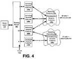
- FIG. 1shows a block diagram overview of an exemplary embodiment of a virtual private network (VPN);
- VPNvirtual private network
- the home agent 130may utilize other remote access software products, such as RADIUS (Remote Authentication Dial In User Service) or DIAMETER software. These protocols may be utilized during communication with the access server 150 . Further, previously described connection mechanisms may also utilize the RADIUS protocol, which is described in RFC 2865, “Remote Authentication Dial In User Service (RADIUS)”, the contents of which are incorporated in its entirety herein by reference. It should be understood that a number of other commercially available or known home agents and connection protocols may also be utilized with the present embodiment.
- RADIUSRemote Authentication Dial In User Service
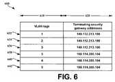
- each of the initiating security gateways 140 a–dmay include the entire selector table 600 .
- each initiating security gateway 140 a–dmay store a portion of the selector table 600 relevant to the VLAN tag(s) associated with that initiating security gateway 140 a–d.
- the initiating security gateway 140 amay store entry 632 corresponding to VLAN tag “ 1 ”
- the initiating security gateway 140 cmay store entries 636 , 638 , and 642 , corresponding to VLAN tags “ 3 ” and “ 5 ”.
- the home agent 130 and the initiating security gateway 140may be stored within the same housing and be part of a single hardware component, and the single hardware component may also perform compression/decompression procedures. It is therefore intended that the foregoing description illustrates rather than limits this invention and that it is the following claims, including all of the equivalents, which define this invention:
Landscapes
- Engineering & Computer Science (AREA)
- Computer Networks & Wireless Communication (AREA)
- Signal Processing (AREA)
- Computer Security & Cryptography (AREA)
- Computer Hardware Design (AREA)
- Computing Systems (AREA)
- General Engineering & Computer Science (AREA)
- Data Exchanges In Wide-Area Networks (AREA)
Abstract
Description
Claims (32)
Priority Applications (4)
| Application Number | Priority Date | Filing Date | Title |
|---|---|---|---|
| US10/279,364US7062566B2 (en) | 2002-10-24 | 2002-10-24 | System and method for using virtual local area network tags with a virtual private network |
| AU2003287191AAU2003287191A1 (en) | 2002-10-24 | 2003-10-23 | System and method for using virtual local area network tags with a private network |
| PCT/US2003/033643WO2004038559A2 (en) | 2002-10-24 | 2003-10-23 | System and method for using virtual local area network tags with a private network |
| TW092129674ATW200420071A (en) | 2002-10-24 | 2003-10-24 | System and method for using virtual local area network tags with a virtual private network |
Applications Claiming Priority (1)
| Application Number | Priority Date | Filing Date | Title |
|---|---|---|---|
| US10/279,364US7062566B2 (en) | 2002-10-24 | 2002-10-24 | System and method for using virtual local area network tags with a virtual private network |
Publications (2)
| Publication Number | Publication Date |
|---|---|
| US20040083295A1 US20040083295A1 (en) | 2004-04-29 |
| US7062566B2true US7062566B2 (en) | 2006-06-13 |
Family
ID=32106689
Family Applications (1)
| Application Number | Title | Priority Date | Filing Date |
|---|---|---|---|
| US10/279,364Expired - LifetimeUS7062566B2 (en) | 2002-10-24 | 2002-10-24 | System and method for using virtual local area network tags with a virtual private network |
Country Status (4)
| Country | Link |
|---|---|
| US (1) | US7062566B2 (en) |
| AU (1) | AU2003287191A1 (en) |
| TW (1) | TW200420071A (en) |
| WO (1) | WO2004038559A2 (en) |
Cited By (90)
| Publication number | Priority date | Publication date | Assignee | Title |
|---|---|---|---|---|
| US20040139313A1 (en)* | 2002-12-05 | 2004-07-15 | Buer Mark L. | Tagging mechanism for data path security processing |
| US20040143734A1 (en)* | 2002-12-05 | 2004-07-22 | Buer Mark L. | Data path security processing |
| US20040148430A1 (en)* | 2003-01-24 | 2004-07-29 | Narayanan Ram Gopal Lakshmi | Establishing communication tunnels |
| US20040219543A1 (en)* | 2001-04-02 | 2004-11-04 | Ralph Wirtz | Method for specifically detecting, isolating and characterizing cells from body samples by transfecting nucleic acid constructs |
| US20040266420A1 (en)* | 2003-06-24 | 2004-12-30 | Nokia Inc. | System and method for secure mobile connectivity |
| US20050055570A1 (en)* | 2003-09-04 | 2005-03-10 | Foundry Networks, Inc. | Multiple tiered network security system, method and apparatus using dynamic user policy assignment |
| US20050182941A1 (en)* | 2004-02-16 | 2005-08-18 | Microsoft Corporation | Generic security claim processing model |
| US20050180358A1 (en)* | 2004-02-13 | 2005-08-18 | Trapeze Networks, Inc. | Station mobility between access points |
| US20050182957A1 (en)* | 2004-02-16 | 2005-08-18 | Microsoft Corporation | Security scopes and profiles |
| US20050193202A1 (en)* | 2004-02-26 | 2005-09-01 | Microsoft Corporation | Digests to identify elements in a signature process |
| US20060130136A1 (en)* | 2004-12-01 | 2006-06-15 | Vijay Devarapalli | Method and system for providing wireless data network interworking |
| US20070086378A1 (en)* | 2005-10-13 | 2007-04-19 | Matta Sudheer P C | System and method for wireless network monitoring |
| US7298702B1 (en)* | 2002-12-20 | 2007-11-20 | Sprint Spectrum L.P. | Method and system for providing remote telephone service via a wireless local area network |
| US20080072226A1 (en)* | 2006-06-22 | 2008-03-20 | American Express Travel Related Services Co., Inc. A New York Corporation | Systems, Methods, and Computer Program Products for Transaction Based Load Balancing |
| US20080151844A1 (en)* | 2006-12-20 | 2008-06-26 | Manish Tiwari | Wireless access point authentication system and method |
| US20080159319A1 (en)* | 2006-12-28 | 2008-07-03 | Matthew Stuart Gast | System and method for aggregation and queuing in a wireless network |
| US20080276085A1 (en)* | 2007-05-02 | 2008-11-06 | Cisco Technology, Inc. | Allowing differential processing of encrypted tunnels |
| US20090016259A1 (en)* | 2007-07-13 | 2009-01-15 | Nortel Networks Limited | Quality of service control in multiple hop wireless communication environments |
| US7516487B1 (en) | 2003-05-21 | 2009-04-07 | Foundry Networks, Inc. | System and method for source IP anti-spoofing security |
| US7523485B1 (en) | 2003-05-21 | 2009-04-21 | Foundry Networks, Inc. | System and method for source IP anti-spoofing security |
| US20090274060A1 (en)* | 2005-10-13 | 2009-11-05 | Trapeze Networks, Inc. | System and method for remote monitoring in a wireless network |
| US7633909B1 (en) | 2002-12-20 | 2009-12-15 | Sprint Spectrum L.P. | Method and system for providing multiple connections from a common wireless access point |
| US20090323531A1 (en)* | 2006-06-01 | 2009-12-31 | Trapeze Networks, Inc. | Wireless load balancing |
| US20100077447A1 (en)* | 2005-12-28 | 2010-03-25 | Foundry Networks, Inc. | Authentication techniques |
| US20100118882A1 (en)* | 2008-11-10 | 2010-05-13 | H3C Technologies Co., Ltd. | Method, Apparatus, and System For Packet Transmission |
| US7724704B2 (en) | 2006-07-17 | 2010-05-25 | Beiden Inc. | Wireless VLAN system and method |
| US7768941B1 (en)* | 2002-08-28 | 2010-08-03 | Sprint Spectrum L.P. | Method and system for initiating a virtual private network over a shared network on behalf of a wireless terminal |
| US7774833B1 (en) | 2003-09-23 | 2010-08-10 | Foundry Networks, Inc. | System and method for protecting CPU against remote access attacks |
| US20100246426A1 (en)* | 2009-03-25 | 2010-09-30 | Christian Berge | Method allowing a monitoring system of the network of an operator to classify ip flows |
| US20100325700A1 (en)* | 2003-08-01 | 2010-12-23 | Brocade Communications Systems, Inc. | System, method and apparatus for providing multiple access modes in a data communications network |
| US7865713B2 (en) | 2006-12-28 | 2011-01-04 | Trapeze Networks, Inc. | Application-aware wireless network system and method |
| US20110023125A1 (en)* | 2009-07-24 | 2011-01-27 | Yongbum Kim | Method and system for integrating remote devices into a domestic vlan |
| US7912982B2 (en) | 2006-06-09 | 2011-03-22 | Trapeze Networks, Inc. | Wireless routing selection system and method |
| US20110113490A1 (en)* | 2005-12-28 | 2011-05-12 | Foundry Networks, Llc | Techniques for preventing attacks on computer systems and networks |
| WO2011120381A1 (en)* | 2010-04-01 | 2011-10-06 | 中兴通讯股份有限公司 | Quality of service processing method and device for virtual private network traffic |
| US8072952B2 (en) | 2006-10-16 | 2011-12-06 | Juniper Networks, Inc. | Load balancing |
| US8150357B2 (en) | 2008-03-28 | 2012-04-03 | Trapeze Networks, Inc. | Smoothing filter for irregular update intervals |
| US8161278B2 (en) | 2005-03-15 | 2012-04-17 | Trapeze Networks, Inc. | System and method for distributing keys in a wireless network |
| US8238298B2 (en) | 2008-08-29 | 2012-08-07 | Trapeze Networks, Inc. | Picking an optimal channel for an access point in a wireless network |
| US8238942B2 (en) | 2007-11-21 | 2012-08-07 | Trapeze Networks, Inc. | Wireless station location detection |
| US8270408B2 (en) | 2005-10-13 | 2012-09-18 | Trapeze Networks, Inc. | Identity-based networking |
| US8340110B2 (en) | 2006-09-15 | 2012-12-25 | Trapeze Networks, Inc. | Quality of service provisioning for wireless networks |
| US8457031B2 (en) | 2005-10-13 | 2013-06-04 | Trapeze Networks, Inc. | System and method for reliable multicast |
| US8474023B2 (en) | 2008-05-30 | 2013-06-25 | Juniper Networks, Inc. | Proactive credential caching |
| US8509128B2 (en) | 2007-09-18 | 2013-08-13 | Trapeze Networks, Inc. | High level instruction convergence function |
| US8528071B1 (en) | 2003-12-05 | 2013-09-03 | Foundry Networks, Llc | System and method for flexible authentication in a data communications network |
| US8542836B2 (en) | 2010-12-01 | 2013-09-24 | Juniper Networks, Inc. | System, apparatus and methods for highly scalable continuous roaming within a wireless network |
| US8612744B2 (en) | 2011-02-10 | 2013-12-17 | Varmour Networks, Inc. | Distributed firewall architecture using virtual machines |
| US8638762B2 (en) | 2005-10-13 | 2014-01-28 | Trapeze Networks, Inc. | System and method for network integrity |
| US8813169B2 (en) | 2011-11-03 | 2014-08-19 | Varmour Networks, Inc. | Virtual security boundary for physical or virtual network devices |
| US8818322B2 (en) | 2006-06-09 | 2014-08-26 | Trapeze Networks, Inc. | Untethered access point mesh system and method |
| US8902904B2 (en) | 2007-09-07 | 2014-12-02 | Trapeze Networks, Inc. | Network assignment based on priority |
| US8964747B2 (en) | 2006-05-03 | 2015-02-24 | Trapeze Networks, Inc. | System and method for restricting network access using forwarding databases |
| US8966018B2 (en) | 2006-05-19 | 2015-02-24 | Trapeze Networks, Inc. | Automated network device configuration and network deployment |
| US8978105B2 (en) | 2008-07-25 | 2015-03-10 | Trapeze Networks, Inc. | Affirming network relationships and resource access via related networks |
| US9191327B2 (en) | 2011-02-10 | 2015-11-17 | Varmour Networks, Inc. | Distributed service processing of network gateways using virtual machines |
| US9191799B2 (en) | 2006-06-09 | 2015-11-17 | Juniper Networks, Inc. | Sharing data between wireless switches system and method |
| US9258702B2 (en) | 2006-06-09 | 2016-02-09 | Trapeze Networks, Inc. | AP-local dynamic switching |
| US9294442B1 (en) | 2015-03-30 | 2016-03-22 | Varmour Networks, Inc. | System and method for threat-driven security policy controls |
| US9380027B1 (en) | 2015-03-30 | 2016-06-28 | Varmour Networks, Inc. | Conditional declarative policies |
| US9438634B1 (en) | 2015-03-13 | 2016-09-06 | Varmour Networks, Inc. | Microsegmented networks that implement vulnerability scanning |
| US9467476B1 (en) | 2015-03-13 | 2016-10-11 | Varmour Networks, Inc. | Context aware microsegmentation |
| US9483317B1 (en) | 2015-08-17 | 2016-11-01 | Varmour Networks, Inc. | Using multiple central processing unit cores for packet forwarding in virtualized networks |
| US9521115B1 (en) | 2016-03-24 | 2016-12-13 | Varmour Networks, Inc. | Security policy generation using container metadata |
| US9525697B2 (en) | 2015-04-02 | 2016-12-20 | Varmour Networks, Inc. | Delivering security functions to distributed networks |
| US9529995B2 (en) | 2011-11-08 | 2016-12-27 | Varmour Networks, Inc. | Auto discovery of virtual machines |
| US9560081B1 (en) | 2016-06-24 | 2017-01-31 | Varmour Networks, Inc. | Data network microsegmentation |
| US9609026B2 (en) | 2015-03-13 | 2017-03-28 | Varmour Networks, Inc. | Segmented networks that implement scanning |
| US9680852B1 (en) | 2016-01-29 | 2017-06-13 | Varmour Networks, Inc. | Recursive multi-layer examination for computer network security remediation |
| US9762599B2 (en) | 2016-01-29 | 2017-09-12 | Varmour Networks, Inc. | Multi-node affinity-based examination for computer network security remediation |
| US9787639B1 (en) | 2016-06-24 | 2017-10-10 | Varmour Networks, Inc. | Granular segmentation using events |
| US9973472B2 (en) | 2015-04-02 | 2018-05-15 | Varmour Networks, Inc. | Methods and systems for orchestrating physical and virtual switches to enforce security boundaries |
| US10009381B2 (en) | 2015-03-30 | 2018-06-26 | Varmour Networks, Inc. | System and method for threat-driven security policy controls |
| US10091238B2 (en) | 2014-02-11 | 2018-10-02 | Varmour Networks, Inc. | Deception using distributed threat detection |
| US10178070B2 (en) | 2015-03-13 | 2019-01-08 | Varmour Networks, Inc. | Methods and systems for providing security to distributed microservices |
| US10193929B2 (en) | 2015-03-13 | 2019-01-29 | Varmour Networks, Inc. | Methods and systems for improving analytics in distributed networks |
| US10191758B2 (en) | 2015-12-09 | 2019-01-29 | Varmour Networks, Inc. | Directing data traffic between intra-server virtual machines |
| US10264025B2 (en) | 2016-06-24 | 2019-04-16 | Varmour Networks, Inc. | Security policy generation for virtualization, bare-metal server, and cloud computing environments |
| US10755334B2 (en) | 2016-06-30 | 2020-08-25 | Varmour Networks, Inc. | Systems and methods for continually scoring and segmenting open opportunities using client data and product predictors |
| US11290493B2 (en) | 2019-05-31 | 2022-03-29 | Varmour Networks, Inc. | Template-driven intent-based security |
| US11290494B2 (en) | 2019-05-31 | 2022-03-29 | Varmour Networks, Inc. | Reliability prediction for cloud security policies |
| US11310284B2 (en) | 2019-05-31 | 2022-04-19 | Varmour Networks, Inc. | Validation of cloud security policies |
| US11575563B2 (en) | 2019-05-31 | 2023-02-07 | Varmour Networks, Inc. | Cloud security management |
| US11711374B2 (en) | 2019-05-31 | 2023-07-25 | Varmour Networks, Inc. | Systems and methods for understanding identity and organizational access to applications within an enterprise environment |
| US11734316B2 (en) | 2021-07-08 | 2023-08-22 | Varmour Networks, Inc. | Relationship-based search in a computing environment |
| US11777978B2 (en) | 2021-01-29 | 2023-10-03 | Varmour Networks, Inc. | Methods and systems for accurately assessing application access risk |
| US11818152B2 (en) | 2020-12-23 | 2023-11-14 | Varmour Networks, Inc. | Modeling topic-based message-oriented middleware within a security system |
| US11863580B2 (en) | 2019-05-31 | 2024-01-02 | Varmour Networks, Inc. | Modeling application dependencies to identify operational risk |
| US11876817B2 (en) | 2020-12-23 | 2024-01-16 | Varmour Networks, Inc. | Modeling queue-based message-oriented middleware relationships in a security system |
| US12050693B2 (en) | 2021-01-29 | 2024-07-30 | Varmour Networks, Inc. | System and method for attributing user behavior from multiple technical telemetry sources |
Families Citing this family (88)
| Publication number | Priority date | Publication date | Assignee | Title |
|---|---|---|---|---|
| US7120791B2 (en)* | 2002-01-25 | 2006-10-10 | Cranite Systems, Inc. | Bridged cryptographic VLAN |
| US7986937B2 (en)* | 2001-12-20 | 2011-07-26 | Microsoft Corporation | Public access point |
| US7188364B2 (en)* | 2001-12-20 | 2007-03-06 | Cranite Systems, Inc. | Personal virtual bridged local area networks |
| AU2003279950A1 (en) | 2002-10-10 | 2004-05-04 | Rocksteady Networks, Inc. | System and method for providing access control |
| WO2004036371A2 (en) | 2002-10-16 | 2004-04-29 | Rocksteady Networks, Inc. | System and method for dynamic bandwidth provisioning |
| US7567510B2 (en)* | 2003-02-13 | 2009-07-28 | Cisco Technology, Inc. | Security groups |
| US20040162996A1 (en)* | 2003-02-18 | 2004-08-19 | Nortel Networks Limited | Distributed security for industrial networks |
| US7624438B2 (en) | 2003-08-20 | 2009-11-24 | Eric White | System and method for providing a secure connection between networked computers |
| US7574603B2 (en)* | 2003-11-14 | 2009-08-11 | Microsoft Corporation | Method of negotiating security parameters and authenticating users interconnected to a network |
| US7706382B2 (en) | 2004-01-30 | 2010-04-27 | Hewlett-Packard Development Company, L.P. | Method and system for managing a network having multiple domains |
| GB0404444D0 (en)* | 2004-02-27 | 2004-09-01 | Bae Sys Defence Sys Ltd | Secure computer communication |
| US7610621B2 (en)* | 2004-03-10 | 2009-10-27 | Eric White | System and method for behavior-based firewall modeling |
| US7665130B2 (en)* | 2004-03-10 | 2010-02-16 | Eric White | System and method for double-capture/double-redirect to a different location |
| US8543710B2 (en)* | 2004-03-10 | 2013-09-24 | Rpx Corporation | Method and system for controlling network access |
| US7562389B1 (en) | 2004-07-30 | 2009-07-14 | Cisco Technology, Inc. | Method and system for network security |
| US7555774B2 (en)* | 2004-08-02 | 2009-06-30 | Cisco Technology, Inc. | Inline intrusion detection using a single physical port |
| US20060190990A1 (en)* | 2005-02-23 | 2006-08-24 | Shimon Gruper | Method and system for controlling access to a service provided through a network |
| JP4695465B2 (en)* | 2004-09-28 | 2011-06-08 | 株式会社リコー | Image forming apparatus, hardware control method, and hardware control program |
| US7937761B1 (en)* | 2004-12-17 | 2011-05-03 | Symantec Corporation | Differential threat detection processing |
| JP4759382B2 (en)* | 2004-12-21 | 2011-08-31 | 株式会社リコー | COMMUNICATION DEVICE, COMMUNICATION METHOD, COMMUNICATION PROGRAM, AND RECORDING MEDIUM |
| US7725938B2 (en) | 2005-01-20 | 2010-05-25 | Cisco Technology, Inc. | Inline intrusion detection |
| WO2006136183A1 (en)* | 2005-06-20 | 2006-12-28 | Telefonaktiebolaget L M Ericsson (Publ) | Quality of service in vlan-based access networks |
| US20070006294A1 (en)* | 2005-06-30 | 2007-01-04 | Hunter G K | Secure flow control for a data flow in a computer and data flow in a computer network |
| US20070011448A1 (en)* | 2005-07-06 | 2007-01-11 | Microsoft Corporation | Using non 5-tuple information with IPSec |
| US20070067381A1 (en)* | 2005-09-19 | 2007-03-22 | The Sco Group, Inc. | Systems and methods for providing distributed applications and services for intelligent mobile devices |
| US8576846B2 (en)* | 2005-10-05 | 2013-11-05 | Qualcomm Incorporated | Peer-to-peer communication in ad hoc wireless network |
| US8635450B2 (en)* | 2005-12-28 | 2014-01-21 | Intel Corporation | IP encapsulation with exposed classifiers |
| US20070204158A1 (en)* | 2006-02-28 | 2007-08-30 | Symbol Technologies, Inc. | Methods and apparatus for encryption key management |
| US8023479B2 (en) | 2006-03-02 | 2011-09-20 | Tango Networks, Inc. | Mobile application gateway for connecting devices on a cellular network with individual enterprise and data networks |
| US7843901B2 (en) | 2006-03-02 | 2010-11-30 | Tango Networks, Inc. | Call flow system and method for use in a legacy telecommunication system |
| US11405846B2 (en) | 2006-03-02 | 2022-08-02 | Tango Networks, Inc. | Call flow system and method for use in a legacy telecommunication system |
| US8175053B2 (en)* | 2006-03-02 | 2012-05-08 | Tango Networks, Inc. | System and method for enabling VPN-less session setup for connecting mobile data devices to an enterprise data network |
| US7890096B2 (en) | 2006-03-02 | 2011-02-15 | Tango Networks, Inc. | System and method for enabling call originations using SMS and hotline capabilities |
| ATE473586T1 (en)* | 2006-04-28 | 2010-07-15 | Koninkl Kpn Nv | CASCADE OF OUT-OF-BOX SERVICES |
| US7849505B2 (en)* | 2006-08-17 | 2010-12-07 | At&T Intellectual Property I, Lp | System and method of selecting a virtual private network access server |
| US8379638B2 (en)* | 2006-09-25 | 2013-02-19 | Certes Networks, Inc. | Security encapsulation of ethernet frames |
| US8607302B2 (en)* | 2006-11-29 | 2013-12-10 | Red Hat, Inc. | Method and system for sharing labeled information between different security realms |
| US7853691B2 (en)* | 2006-11-29 | 2010-12-14 | Broadcom Corporation | Method and system for securing a network utilizing IPsec and MACsec protocols |
| KR101323852B1 (en)* | 2007-07-12 | 2013-10-31 | 삼성전자주식회사 | Virtual firewall system based on public security policy and its control method |
| US8156541B1 (en)* | 2007-10-17 | 2012-04-10 | Mcafee, Inc. | System, method, and computer program product for identifying unwanted activity utilizing a honeypot device accessible via VLAN trunking |
| US8576874B2 (en) | 2007-10-30 | 2013-11-05 | Qualcomm Incorporated | Methods and apparatus to provide a virtual network interface |
| TWI366376B (en)* | 2008-06-11 | 2012-06-11 | Chunghwa Telecom Co Ltd | System and method identity verification applicable to exclusive simulation network |
| US10411975B2 (en) | 2013-03-15 | 2019-09-10 | Csc Agility Platform, Inc. | System and method for a cloud computing abstraction with multi-tier deployment policy |
| US9489647B2 (en) | 2008-06-19 | 2016-11-08 | Csc Agility Platform, Inc. | System and method for a cloud computing abstraction with self-service portal for publishing resources |
| US20140201017A1 (en) | 2008-06-19 | 2014-07-17 | Servicemesh, Inc. | Systems and methods for providing repeated use of computing resources |
| AU2009259876A1 (en) | 2008-06-19 | 2009-12-23 | Servicemesh, Inc. | Cloud computing gateway, cloud computing hypervisor, and methods for implementing same |
| US9069599B2 (en)* | 2008-06-19 | 2015-06-30 | Servicemesh, Inc. | System and method for a cloud computing abstraction layer with security zone facilities |
| CN101621503A (en)* | 2008-06-30 | 2010-01-06 | 中华电信股份有限公司 | Identity recognition system and method applied to virtual private network architecture |
| US20100011099A1 (en)* | 2008-07-09 | 2010-01-14 | General Instrument Corporation | Method and apparatus for monitoring and logging communication sessions |
| US8010085B2 (en)* | 2008-11-19 | 2011-08-30 | Zscaler, Inc. | Traffic redirection in cloud based security services |
| US8918631B1 (en)* | 2009-03-31 | 2014-12-23 | Juniper Networks, Inc. | Methods and apparatus for dynamic automated configuration within a control plane of a switch fabric |
| US9129295B2 (en) | 2010-02-28 | 2015-09-08 | Microsoft Technology Licensing, Llc | See-through near-eye display glasses with a fast response photochromic film system for quick transition from dark to clear |
| US9097891B2 (en) | 2010-02-28 | 2015-08-04 | Microsoft Technology Licensing, Llc | See-through near-eye display glasses including an auto-brightness control for the display brightness based on the brightness in the environment |
| US20150309316A1 (en) | 2011-04-06 | 2015-10-29 | Microsoft Technology Licensing, Llc | Ar glasses with predictive control of external device based on event input |
| US9341843B2 (en) | 2010-02-28 | 2016-05-17 | Microsoft Technology Licensing, Llc | See-through near-eye display glasses with a small scale image source |
| US9366862B2 (en) | 2010-02-28 | 2016-06-14 | Microsoft Technology Licensing, Llc | System and method for delivering content to a group of see-through near eye display eyepieces |
| US9134534B2 (en) | 2010-02-28 | 2015-09-15 | Microsoft Technology Licensing, Llc | See-through near-eye display glasses including a modular image source |
| US9759917B2 (en) | 2010-02-28 | 2017-09-12 | Microsoft Technology Licensing, Llc | AR glasses with event and sensor triggered AR eyepiece interface to external devices |
| US9182596B2 (en) | 2010-02-28 | 2015-11-10 | Microsoft Technology Licensing, Llc | See-through near-eye display glasses with the optical assembly including absorptive polarizers or anti-reflective coatings to reduce stray light |
| US9128281B2 (en) | 2010-09-14 | 2015-09-08 | Microsoft Technology Licensing, Llc | Eyepiece with uniformly illuminated reflective display |
| US9091851B2 (en) | 2010-02-28 | 2015-07-28 | Microsoft Technology Licensing, Llc | Light control in head mounted displays |
| US9223134B2 (en) | 2010-02-28 | 2015-12-29 | Microsoft Technology Licensing, Llc | Optical imperfections in a light transmissive illumination system for see-through near-eye display glasses |
| US9229227B2 (en) | 2010-02-28 | 2016-01-05 | Microsoft Technology Licensing, Llc | See-through near-eye display glasses with a light transmissive wedge shaped illumination system |
| US9285589B2 (en) | 2010-02-28 | 2016-03-15 | Microsoft Technology Licensing, Llc | AR glasses with event and sensor triggered control of AR eyepiece applications |
| WO2011106797A1 (en) | 2010-02-28 | 2011-09-01 | Osterhout Group, Inc. | Projection triggering through an external marker in an augmented reality eyepiece |
| US10180572B2 (en) | 2010-02-28 | 2019-01-15 | Microsoft Technology Licensing, Llc | AR glasses with event and user action control of external applications |
| US9097890B2 (en) | 2010-02-28 | 2015-08-04 | Microsoft Technology Licensing, Llc | Grating in a light transmissive illumination system for see-through near-eye display glasses |
| US20120249797A1 (en) | 2010-02-28 | 2012-10-04 | Osterhout Group, Inc. | Head-worn adaptive display |
| WO2011151095A1 (en)* | 2010-06-01 | 2011-12-08 | Nokia Siemens Networks Oy | Method of connecting a mobile station to a communications network |
| US9794220B2 (en)* | 2010-08-31 | 2017-10-17 | Comcast Cable Communications, Llc | Wireless extension of broadband access |
| US8935427B2 (en)* | 2010-09-23 | 2015-01-13 | Microsoft Corporation | Providing virtual networks using multi-tenant relays |
| US9240928B2 (en)* | 2010-12-14 | 2016-01-19 | Telefonaktiebolaget L M Ericsson (Publ) | Data plane for resilient network interconnect |
| US8972555B2 (en)* | 2011-03-04 | 2015-03-03 | Unisys Corporation | IPsec connection to private networks |
| US8464335B1 (en)* | 2011-03-18 | 2013-06-11 | Zscaler, Inc. | Distributed, multi-tenant virtual private network cloud systems and methods for mobile security and policy enforcement |
| US9300570B2 (en)* | 2012-05-22 | 2016-03-29 | Harris Corporation | Multi-tunnel virtual private network |
| CN103024852B (en)* | 2012-11-27 | 2015-08-05 | 华为技术有限公司 | The method and apparatus that business forwards |
| TWI506470B (en)* | 2013-10-29 | 2015-11-01 | Chunghwa Telecom Co Ltd | The IP Routing Level Control System and Its Method on Multi - virtual Desktop Service |
| US9356912B2 (en)* | 2014-08-20 | 2016-05-31 | Alcatel Lucent | Method for load-balancing IPsec traffic |
| CN104394122B (en)* | 2014-10-31 | 2017-06-27 | 杭州安恒信息技术有限公司 | A HTTP Service Firewall Based on Adaptive Proxy Mechanism |
| TWI577156B (en)* | 2014-12-26 | 2017-04-01 | Network gateway device for data inspection, method and computer program products | |
| CN106027354B (en)* | 2016-05-19 | 2019-03-15 | 杭州迪普科技股份有限公司 | The reflow method and device of VPN client |
| US11909603B2 (en)* | 2017-12-01 | 2024-02-20 | Cisco Technology, Inc. | Priority based resource management in a network functions virtualization (NFV) environment |
| US11211999B2 (en)* | 2017-12-28 | 2021-12-28 | Hughes Network Systems, Llc | Satellite network virtual LAN usage |
| US11206318B2 (en)* | 2019-04-16 | 2021-12-21 | Abb Schweiz Ag | Cloud interoperability |
| US11765146B2 (en)* | 2020-08-25 | 2023-09-19 | Cisco Technology, Inc. | Partial packet encryption for encrypted tunnels |
| CN115694862A (en)* | 2021-07-31 | 2023-02-03 | 华为技术有限公司 | Access control method, client agent device, gateway device and related system |
| CN115314448B (en)* | 2022-08-11 | 2023-12-05 | 北京百度网讯科技有限公司 | Method and device for accessing cloud network, electronic equipment and computer medium |
| US20250039090A1 (en)* | 2023-07-25 | 2025-01-30 | Charlotte Wi-Fi Inc., a North Carolina S Corp. | Methods and systems for dynamic network interconnections |
Citations (9)
| Publication number | Priority date | Publication date | Assignee | Title |
|---|---|---|---|---|
| US5787428A (en)* | 1994-02-16 | 1998-07-28 | British Telecommunications Public Limited Company | Control of database access using security/user tag correspondence table |
| US6151628A (en) | 1997-07-03 | 2000-11-21 | 3Com Corporation | Network access methods, including direct wireless to internet access |
| US6253321B1 (en)* | 1998-06-19 | 2001-06-26 | Ssh Communications Security Ltd. | Method and arrangement for implementing IPSEC policy management using filter code |
| US6330562B1 (en)* | 1999-01-29 | 2001-12-11 | International Business Machines Corporation | System and method for managing security objects |
| US6425085B2 (en)* | 1997-07-17 | 2002-07-23 | Canon Kabushiki Kaisha | Terminal device and method for requesting user certification from host computer |
| US6438612B1 (en)* | 1998-09-11 | 2002-08-20 | Ssh Communications Security, Ltd. | Method and arrangement for secure tunneling of data between virtual routers |
| US6539483B1 (en)* | 2000-01-12 | 2003-03-25 | International Business Machines Corporation | System and method for generation VPN network policies |
| US6587466B1 (en)* | 1999-05-27 | 2003-07-01 | International Business Machines Corporation | Search tree for policy based packet classification in communication networks |
| US6708218B1 (en)* | 2000-06-05 | 2004-03-16 | International Business Machines Corporation | IpSec performance enhancement using a hardware-based parallel process |
- 2002
- 2002-10-24USUS10/279,364patent/US7062566B2/ennot_activeExpired - Lifetime
- 2003
- 2003-10-23WOPCT/US2003/033643patent/WO2004038559A2/ennot_activeApplication Discontinuation
- 2003-10-23AUAU2003287191Apatent/AU2003287191A1/ennot_activeAbandoned
- 2003-10-24TWTW092129674Apatent/TW200420071A/enunknown
Patent Citations (9)
| Publication number | Priority date | Publication date | Assignee | Title |
|---|---|---|---|---|
| US5787428A (en)* | 1994-02-16 | 1998-07-28 | British Telecommunications Public Limited Company | Control of database access using security/user tag correspondence table |
| US6151628A (en) | 1997-07-03 | 2000-11-21 | 3Com Corporation | Network access methods, including direct wireless to internet access |
| US6425085B2 (en)* | 1997-07-17 | 2002-07-23 | Canon Kabushiki Kaisha | Terminal device and method for requesting user certification from host computer |
| US6253321B1 (en)* | 1998-06-19 | 2001-06-26 | Ssh Communications Security Ltd. | Method and arrangement for implementing IPSEC policy management using filter code |
| US6438612B1 (en)* | 1998-09-11 | 2002-08-20 | Ssh Communications Security, Ltd. | Method and arrangement for secure tunneling of data between virtual routers |
| US6330562B1 (en)* | 1999-01-29 | 2001-12-11 | International Business Machines Corporation | System and method for managing security objects |
| US6587466B1 (en)* | 1999-05-27 | 2003-07-01 | International Business Machines Corporation | Search tree for policy based packet classification in communication networks |
| US6539483B1 (en)* | 2000-01-12 | 2003-03-25 | International Business Machines Corporation | System and method for generation VPN network policies |
| US6708218B1 (en)* | 2000-06-05 | 2004-03-16 | International Business Machines Corporation | IpSec performance enhancement using a hardware-based parallel process |
Non-Patent Citations (10)
| Title |
|---|
| IEEE Std 802.Q-1998, "IEEE Standards For Local and Metropolitan Area Networks: Virtual Bridged Local Area Networks", IEEE Computer Society. Dec. 1998. |
| International Search Report for PCT Application Serial No. PCT/US03/33643, Dated May 11, 2004. |
| Internet Engineering Task Force (IETF), Requests For Comments (RFC) 2386, "A Framework For QoS-Based Routing In the Internet", Aug. 1998. |
| Internet Engineering Task Force (IETF), Requests For Comments (RFC) 2401, "Security Architecture For the Internet Protocol", Nov. 1998. |
| Internet Engineering Task Force (IETF), Requests For Comments (RFC) 2408, "Internet Security Association and Key Management Protocol (ISAKMP)", Nov. 1998. |
| Internet Engineering Task Force (IETF), Requests For Comments (RFC) 2409, "The Internet Key Exchange (IKE)", Nov. 1998. |
| Internet Engineering Task Force (IETF), Requests For Comments (RFC) 2764, "A Framework For IP Based Virtual Private Networks", Feb. 2000. |
| Internet Engineering Task Force (IETF), Requests For Comments (RFC) 2865, "Remote Authentication Dial In User Service (RADIUS)", Jun. 2000. |
| Internet Engineering Task Force (IETF), Requests For Comments (RFC) 2868, "RADIUS Attributes For Tunnel Protocol Support", Jun. 2000. |
| Internet Engineering Task Force (IETF), Requests For Comments (RFC) 3168, "The Addition of Explicit Congestion Notification (ECN) to IP", Sep. 2001. |
Cited By (170)
| Publication number | Priority date | Publication date | Assignee | Title |
|---|---|---|---|---|
| US20040219543A1 (en)* | 2001-04-02 | 2004-11-04 | Ralph Wirtz | Method for specifically detecting, isolating and characterizing cells from body samples by transfecting nucleic acid constructs |
| US7768941B1 (en)* | 2002-08-28 | 2010-08-03 | Sprint Spectrum L.P. | Method and system for initiating a virtual private network over a shared network on behalf of a wireless terminal |
| US8055895B2 (en)* | 2002-12-05 | 2011-11-08 | Broadcom Corporation | Data path security processing |
| US20040143734A1 (en)* | 2002-12-05 | 2004-07-22 | Buer Mark L. | Data path security processing |
| US20090319775A1 (en)* | 2002-12-05 | 2009-12-24 | Broadcom Corporation | Data Path Security Processing |
| US20040139313A1 (en)* | 2002-12-05 | 2004-07-15 | Buer Mark L. | Tagging mechanism for data path security processing |
| US7587587B2 (en)* | 2002-12-05 | 2009-09-08 | Broadcom Corporation | Data path security processing |
| US9015467B2 (en) | 2002-12-05 | 2015-04-21 | Broadcom Corporation | Tagging mechanism for data path security processing |
| US9125058B2 (en) | 2002-12-20 | 2015-09-01 | Sprint Spectrum L.P. | Method and system for selecting VPN connections in response to wireless network identifiers |
| US7633909B1 (en) | 2002-12-20 | 2009-12-15 | Sprint Spectrum L.P. | Method and system for providing multiple connections from a common wireless access point |
| US8077689B1 (en) | 2002-12-20 | 2011-12-13 | Sprint Spectrum L.P. | Method and system for establishing VPN connections in response to wireless network identifiers |
| US7298702B1 (en)* | 2002-12-20 | 2007-11-20 | Sprint Spectrum L.P. | Method and system for providing remote telephone service via a wireless local area network |
| US20040148430A1 (en)* | 2003-01-24 | 2004-07-29 | Narayanan Ram Gopal Lakshmi | Establishing communication tunnels |
| US7779152B2 (en)* | 2003-01-24 | 2010-08-17 | Nokia Corporation | Establishing communication tunnels |
| US8918875B2 (en) | 2003-05-21 | 2014-12-23 | Foundry Networks, Llc | System and method for ARP anti-spoofing security |
| US20090307773A1 (en)* | 2003-05-21 | 2009-12-10 | Foundry Networks, Inc. | System and method for arp anti-spoofing security |
| US8533823B2 (en) | 2003-05-21 | 2013-09-10 | Foundry Networks, Llc | System and method for source IP anti-spoofing security |
| US8006304B2 (en) | 2003-05-21 | 2011-08-23 | Foundry Networks, Llc | System and method for ARP anti-spoofing security |
| US7979903B2 (en) | 2003-05-21 | 2011-07-12 | Foundry Networks, Llc | System and method for source IP anti-spoofing security |
| US20090260083A1 (en)* | 2003-05-21 | 2009-10-15 | Foundry Networks, Inc. | System and method for source ip anti-spoofing security |
| US7516487B1 (en) | 2003-05-21 | 2009-04-07 | Foundry Networks, Inc. | System and method for source IP anti-spoofing security |
| US7523485B1 (en) | 2003-05-21 | 2009-04-21 | Foundry Networks, Inc. | System and method for source IP anti-spoofing security |
| US7562390B1 (en) | 2003-05-21 | 2009-07-14 | Foundry Networks, Inc. | System and method for ARP anti-spoofing security |
| US8245300B2 (en) | 2003-05-21 | 2012-08-14 | Foundry Networks Llc | System and method for ARP anti-spoofing security |
| US20090254973A1 (en)* | 2003-05-21 | 2009-10-08 | Foundry Networks, Inc. | System and method for source ip anti-spoofing security |
| US20040266420A1 (en)* | 2003-06-24 | 2004-12-30 | Nokia Inc. | System and method for secure mobile connectivity |
| US8681800B2 (en) | 2003-08-01 | 2014-03-25 | Foundry Networks, Llc | System, method and apparatus for providing multiple access modes in a data communications network |
| US7876772B2 (en) | 2003-08-01 | 2011-01-25 | Foundry Networks, Llc | System, method and apparatus for providing multiple access modes in a data communications network |
| US20100325700A1 (en)* | 2003-08-01 | 2010-12-23 | Brocade Communications Systems, Inc. | System, method and apparatus for providing multiple access modes in a data communications network |
| US8249096B2 (en) | 2003-08-01 | 2012-08-21 | Foundry Networks, Llc | System, method and apparatus for providing multiple access modes in a data communications network |
| US8239929B2 (en) | 2003-09-04 | 2012-08-07 | Foundry Networks, Llc | Multiple tiered network security system, method and apparatus using dynamic user policy assignment |
| US20100223654A1 (en)* | 2003-09-04 | 2010-09-02 | Brocade Communications Systems, Inc. | Multiple tiered network security system, method and apparatus using dynamic user policy assignment |
| US20050055570A1 (en)* | 2003-09-04 | 2005-03-10 | Foundry Networks, Inc. | Multiple tiered network security system, method and apparatus using dynamic user policy assignment |
| US7735114B2 (en)* | 2003-09-04 | 2010-06-08 | Foundry Networks, Inc. | Multiple tiered network security system, method and apparatus using dynamic user policy assignment |
| US20100333191A1 (en)* | 2003-09-23 | 2010-12-30 | Foundry Networks, Inc. | System and method for protecting cpu against remote access attacks |
| US8893256B2 (en) | 2003-09-23 | 2014-11-18 | Brocade Communications Systems, Inc. | System and method for protecting CPU against remote access attacks |
| US7774833B1 (en) | 2003-09-23 | 2010-08-10 | Foundry Networks, Inc. | System and method for protecting CPU against remote access attacks |
| US8528071B1 (en) | 2003-12-05 | 2013-09-03 | Foundry Networks, Llc | System and method for flexible authentication in a data communications network |
| US20050180358A1 (en)* | 2004-02-13 | 2005-08-18 | Trapeze Networks, Inc. | Station mobility between access points |
| US7221927B2 (en)* | 2004-02-13 | 2007-05-22 | Trapeze Networks, Inc. | Station mobility between access points |
| US7716728B2 (en)* | 2004-02-16 | 2010-05-11 | Microsoft Corproation | Security scopes and profiles |
| US20050182941A1 (en)* | 2004-02-16 | 2005-08-18 | Microsoft Corporation | Generic security claim processing model |
| US7640573B2 (en) | 2004-02-16 | 2009-12-29 | Microsoft Corporation | Generic security claim processing model |
| US20050182957A1 (en)* | 2004-02-16 | 2005-08-18 | Microsoft Corporation | Security scopes and profiles |
| US20050193202A1 (en)* | 2004-02-26 | 2005-09-01 | Microsoft Corporation | Digests to identify elements in a signature process |
| US7873831B2 (en) | 2004-02-26 | 2011-01-18 | Microsoft Corporation | Digests to identify elements in a signature process |
| US20110078212A1 (en)* | 2004-02-26 | 2011-03-31 | Microsoft Corporation | Digests to Identify Elements in a Signature Process |
| US8725776B2 (en) | 2004-02-26 | 2014-05-13 | Microsoft Corporation | Digests to identify elements in a signature process |
| US20060130136A1 (en)* | 2004-12-01 | 2006-06-15 | Vijay Devarapalli | Method and system for providing wireless data network interworking |
| US8161278B2 (en) | 2005-03-15 | 2012-04-17 | Trapeze Networks, Inc. | System and method for distributing keys in a wireless network |
| US8635444B2 (en) | 2005-03-15 | 2014-01-21 | Trapeze Networks, Inc. | System and method for distributing keys in a wireless network |
| US20090274060A1 (en)* | 2005-10-13 | 2009-11-05 | Trapeze Networks, Inc. | System and method for remote monitoring in a wireless network |
| US20070086378A1 (en)* | 2005-10-13 | 2007-04-19 | Matta Sudheer P C | System and method for wireless network monitoring |
| US8270408B2 (en) | 2005-10-13 | 2012-09-18 | Trapeze Networks, Inc. | Identity-based networking |
| US8457031B2 (en) | 2005-10-13 | 2013-06-04 | Trapeze Networks, Inc. | System and method for reliable multicast |
| US7724703B2 (en) | 2005-10-13 | 2010-05-25 | Belden, Inc. | System and method for wireless network monitoring |
| US8218449B2 (en) | 2005-10-13 | 2012-07-10 | Trapeze Networks, Inc. | System and method for remote monitoring in a wireless network |
| US8514827B2 (en) | 2005-10-13 | 2013-08-20 | Trapeze Networks, Inc. | System and network for wireless network monitoring |
| US8638762B2 (en) | 2005-10-13 | 2014-01-28 | Trapeze Networks, Inc. | System and method for network integrity |
| US8116275B2 (en) | 2005-10-13 | 2012-02-14 | Trapeze Networks, Inc. | System and network for wireless network monitoring |
| US8509106B2 (en) | 2005-12-28 | 2013-08-13 | Foundry Networks, Llc | Techniques for preventing attacks on computer systems and networks |
| US20100077447A1 (en)* | 2005-12-28 | 2010-03-25 | Foundry Networks, Inc. | Authentication techniques |
| US8122485B2 (en) | 2005-12-28 | 2012-02-21 | Foundry Networks, Llc | Authentication techniques |
| US8522311B2 (en) | 2005-12-28 | 2013-08-27 | Foundry Networks, Llc | Authentication techniques |
| US7831996B2 (en) | 2005-12-28 | 2010-11-09 | Foundry Networks, Llc | Authentication techniques |
| US20110113490A1 (en)* | 2005-12-28 | 2011-05-12 | Foundry Networks, Llc | Techniques for preventing attacks on computer systems and networks |
| US20110107399A1 (en)* | 2005-12-28 | 2011-05-05 | Foundry Networks, Llc | Authentication techniques |
| US8964747B2 (en) | 2006-05-03 | 2015-02-24 | Trapeze Networks, Inc. | System and method for restricting network access using forwarding databases |
| US8966018B2 (en) | 2006-05-19 | 2015-02-24 | Trapeze Networks, Inc. | Automated network device configuration and network deployment |
| US8064939B2 (en) | 2006-06-01 | 2011-11-22 | Juniper Networks, Inc. | Wireless load balancing |
| US20090323531A1 (en)* | 2006-06-01 | 2009-12-31 | Trapeze Networks, Inc. | Wireless load balancing |
| US8320949B2 (en) | 2006-06-01 | 2012-11-27 | Juniper Networks, Inc. | Wireless load balancing across bands |
| US10638304B2 (en) | 2006-06-09 | 2020-04-28 | Trapeze Networks, Inc. | Sharing data between wireless switches system and method |
| US11627461B2 (en) | 2006-06-09 | 2023-04-11 | Juniper Networks, Inc. | AP-local dynamic switching |
| US7912982B2 (en) | 2006-06-09 | 2011-03-22 | Trapeze Networks, Inc. | Wireless routing selection system and method |
| US9838942B2 (en) | 2006-06-09 | 2017-12-05 | Trapeze Networks, Inc. | AP-local dynamic switching |
| US12063501B2 (en) | 2006-06-09 | 2024-08-13 | Juniper Networks, Inc. | AP-local dynamic switching |
| US10834585B2 (en) | 2006-06-09 | 2020-11-10 | Trapeze Networks, Inc. | Untethered access point mesh system and method |
| US8818322B2 (en) | 2006-06-09 | 2014-08-26 | Trapeze Networks, Inc. | Untethered access point mesh system and method |
| US11432147B2 (en) | 2006-06-09 | 2022-08-30 | Trapeze Networks, Inc. | Untethered access point mesh system and method |
| US9258702B2 (en) | 2006-06-09 | 2016-02-09 | Trapeze Networks, Inc. | AP-local dynamic switching |
| US10327202B2 (en) | 2006-06-09 | 2019-06-18 | Trapeze Networks, Inc. | AP-local dynamic switching |
| US11758398B2 (en) | 2006-06-09 | 2023-09-12 | Juniper Networks, Inc. | Untethered access point mesh system and method |
| US10798650B2 (en) | 2006-06-09 | 2020-10-06 | Trapeze Networks, Inc. | AP-local dynamic switching |
| US9191799B2 (en) | 2006-06-09 | 2015-11-17 | Juniper Networks, Inc. | Sharing data between wireless switches system and method |
| US20080072226A1 (en)* | 2006-06-22 | 2008-03-20 | American Express Travel Related Services Co., Inc. A New York Corporation | Systems, Methods, and Computer Program Products for Transaction Based Load Balancing |
| US8413160B2 (en)* | 2006-06-22 | 2013-04-02 | American Express Travel Related Services Company, Inc. | Systems, methods, and computer program products for transaction based load balancing |
| US7724704B2 (en) | 2006-07-17 | 2010-05-25 | Beiden Inc. | Wireless VLAN system and method |
| US8340110B2 (en) | 2006-09-15 | 2012-12-25 | Trapeze Networks, Inc. | Quality of service provisioning for wireless networks |
| US8446890B2 (en) | 2006-10-16 | 2013-05-21 | Juniper Networks, Inc. | Load balancing |
| US8072952B2 (en) | 2006-10-16 | 2011-12-06 | Juniper Networks, Inc. | Load balancing |
| US20080151844A1 (en)* | 2006-12-20 | 2008-06-26 | Manish Tiwari | Wireless access point authentication system and method |
| US7873061B2 (en) | 2006-12-28 | 2011-01-18 | Trapeze Networks, Inc. | System and method for aggregation and queuing in a wireless network |
| US7865713B2 (en) | 2006-12-28 | 2011-01-04 | Trapeze Networks, Inc. | Application-aware wireless network system and method |
| US20080159319A1 (en)* | 2006-12-28 | 2008-07-03 | Matthew Stuart Gast | System and method for aggregation and queuing in a wireless network |
| US8670383B2 (en) | 2006-12-28 | 2014-03-11 | Trapeze Networks, Inc. | System and method for aggregation and queuing in a wireless network |
| US8230493B2 (en) | 2007-05-02 | 2012-07-24 | Cisco Technology, Inc. | Allowing differential processing of encrypted tunnels |
| US20080276085A1 (en)* | 2007-05-02 | 2008-11-06 | Cisco Technology, Inc. | Allowing differential processing of encrypted tunnels |
| US20130033986A1 (en)* | 2007-07-13 | 2013-02-07 | Apple Inc. | Quality of Service Control in Multiple Hop Wireless Communication Environments |
| US20090016258A1 (en)* | 2007-07-13 | 2009-01-15 | Nortel Networks Limited | Quality of service control in multiple hop wireless communication environments |
| US9838944B2 (en)* | 2007-07-13 | 2017-12-05 | Apple Inc. | Quality of service control in multiple hop wireless communication environments |
| US20090016259A1 (en)* | 2007-07-13 | 2009-01-15 | Nortel Networks Limited | Quality of service control in multiple hop wireless communication environments |
| US9351200B2 (en)* | 2007-07-13 | 2016-05-24 | Apple Inc. | Quality of service control in multiple hop wireless communication environments |
| US8305897B2 (en)* | 2007-07-13 | 2012-11-06 | Apple Inc. | Quality of service control in multiple hop wireless communication environments |
| US8958300B2 (en)* | 2007-07-13 | 2015-02-17 | Apple Inc. | Quality of service control in multiple hop wireless communication environments |
| US20160255568A1 (en)* | 2007-07-13 | 2016-09-01 | Apple Inc. | Quality of Service Control in Multiple Hop Wireless Communication Environments |
| US9629061B2 (en)* | 2007-07-13 | 2017-04-18 | Apple Inc. | Quality of service control in multiple hop wireless communication environments |
| US8000243B2 (en)* | 2007-07-13 | 2011-08-16 | Nortel Networks Limited | Quality of service control in multiple hop wireless communication environments |
| US20170208530A1 (en)* | 2007-07-13 | 2017-07-20 | Apple Inc. | Quality of Service Control in Multiple Hop Wireless Communication Environments |
| US20150163697A1 (en)* | 2007-07-13 | 2015-06-11 | Apple Inc. | Quality of service control in multiple hop wireless communication environments |
| US8902904B2 (en) | 2007-09-07 | 2014-12-02 | Trapeze Networks, Inc. | Network assignment based on priority |
| US8509128B2 (en) | 2007-09-18 | 2013-08-13 | Trapeze Networks, Inc. | High level instruction convergence function |
| US8238942B2 (en) | 2007-11-21 | 2012-08-07 | Trapeze Networks, Inc. | Wireless station location detection |
| US8150357B2 (en) | 2008-03-28 | 2012-04-03 | Trapeze Networks, Inc. | Smoothing filter for irregular update intervals |
| US8474023B2 (en) | 2008-05-30 | 2013-06-25 | Juniper Networks, Inc. | Proactive credential caching |
| US8978105B2 (en) | 2008-07-25 | 2015-03-10 | Trapeze Networks, Inc. | Affirming network relationships and resource access via related networks |
| US8238298B2 (en) | 2008-08-29 | 2012-08-07 | Trapeze Networks, Inc. | Picking an optimal channel for an access point in a wireless network |
| US20100118882A1 (en)* | 2008-11-10 | 2010-05-13 | H3C Technologies Co., Ltd. | Method, Apparatus, and System For Packet Transmission |
| US8861547B2 (en) | 2008-11-10 | 2014-10-14 | Hangzhou H3C Technologies Co., Ltd. | Method, apparatus, and system for packet transmission |
| US20100246426A1 (en)* | 2009-03-25 | 2010-09-30 | Christian Berge | Method allowing a monitoring system of the network of an operator to classify ip flows |
| US8929229B2 (en)* | 2009-03-25 | 2015-01-06 | Infovista Sa | Method allowing a monitoring system of the network of an operator to classify IP flows |
| US20110023125A1 (en)* | 2009-07-24 | 2011-01-27 | Yongbum Kim | Method and system for integrating remote devices into a domestic vlan |
| US20140173757A1 (en)* | 2009-07-24 | 2014-06-19 | Broadcom Corporation | Method And System For Integrating Remote Devices Into A Domestic VLAN |
| US8707456B2 (en)* | 2009-07-24 | 2014-04-22 | Broadcom Corporation | Method and system for integrating remote devices into a domestic VLAN |
| WO2011120381A1 (en)* | 2010-04-01 | 2011-10-06 | 中兴通讯股份有限公司 | Quality of service processing method and device for virtual private network traffic |
| US8542836B2 (en) | 2010-12-01 | 2013-09-24 | Juniper Networks, Inc. | System, apparatus and methods for highly scalable continuous roaming within a wireless network |
| US9609083B2 (en) | 2011-02-10 | 2017-03-28 | Varmour Networks, Inc. | Distributed service processing of network gateways using virtual machines |
| US8612744B2 (en) | 2011-02-10 | 2013-12-17 | Varmour Networks, Inc. | Distributed firewall architecture using virtual machines |
| US9191327B2 (en) | 2011-02-10 | 2015-11-17 | Varmour Networks, Inc. | Distributed service processing of network gateways using virtual machines |
| US8813169B2 (en) | 2011-11-03 | 2014-08-19 | Varmour Networks, Inc. | Virtual security boundary for physical or virtual network devices |
| US9529995B2 (en) | 2011-11-08 | 2016-12-27 | Varmour Networks, Inc. | Auto discovery of virtual machines |
| US10091238B2 (en) | 2014-02-11 | 2018-10-02 | Varmour Networks, Inc. | Deception using distributed threat detection |
| US10178070B2 (en) | 2015-03-13 | 2019-01-08 | Varmour Networks, Inc. | Methods and systems for providing security to distributed microservices |
| US10158672B2 (en) | 2015-03-13 | 2018-12-18 | Varmour Networks, Inc. | Context aware microsegmentation |
| US9467476B1 (en) | 2015-03-13 | 2016-10-11 | Varmour Networks, Inc. | Context aware microsegmentation |
| US9438634B1 (en) | 2015-03-13 | 2016-09-06 | Varmour Networks, Inc. | Microsegmented networks that implement vulnerability scanning |
| US10110636B2 (en) | 2015-03-13 | 2018-10-23 | Varmour Networks, Inc. | Segmented networks that implement scanning |
| US10193929B2 (en) | 2015-03-13 | 2019-01-29 | Varmour Networks, Inc. | Methods and systems for improving analytics in distributed networks |
| US9609026B2 (en) | 2015-03-13 | 2017-03-28 | Varmour Networks, Inc. | Segmented networks that implement scanning |
| US9621595B2 (en) | 2015-03-30 | 2017-04-11 | Varmour Networks, Inc. | Conditional declarative policies |
| US10009381B2 (en) | 2015-03-30 | 2018-06-26 | Varmour Networks, Inc. | System and method for threat-driven security policy controls |
| US9380027B1 (en) | 2015-03-30 | 2016-06-28 | Varmour Networks, Inc. | Conditional declarative policies |
| US9294442B1 (en) | 2015-03-30 | 2016-03-22 | Varmour Networks, Inc. | System and method for threat-driven security policy controls |
| US10333986B2 (en) | 2015-03-30 | 2019-06-25 | Varmour Networks, Inc. | Conditional declarative policies |
| US10084753B2 (en) | 2015-04-02 | 2018-09-25 | Varmour Networks, Inc. | Delivering security functions to distributed networks |
| US9973472B2 (en) | 2015-04-02 | 2018-05-15 | Varmour Networks, Inc. | Methods and systems for orchestrating physical and virtual switches to enforce security boundaries |
| US9525697B2 (en) | 2015-04-02 | 2016-12-20 | Varmour Networks, Inc. | Delivering security functions to distributed networks |
| US9483317B1 (en) | 2015-08-17 | 2016-11-01 | Varmour Networks, Inc. | Using multiple central processing unit cores for packet forwarding in virtualized networks |
| US10191758B2 (en) | 2015-12-09 | 2019-01-29 | Varmour Networks, Inc. | Directing data traffic between intra-server virtual machines |
| US9680852B1 (en) | 2016-01-29 | 2017-06-13 | Varmour Networks, Inc. | Recursive multi-layer examination for computer network security remediation |
| US9762599B2 (en) | 2016-01-29 | 2017-09-12 | Varmour Networks, Inc. | Multi-node affinity-based examination for computer network security remediation |
| US10382467B2 (en) | 2016-01-29 | 2019-08-13 | Varmour Networks, Inc. | Recursive multi-layer examination for computer network security remediation |
| US10009317B2 (en) | 2016-03-24 | 2018-06-26 | Varmour Networks, Inc. | Security policy generation using container metadata |
| US9521115B1 (en) | 2016-03-24 | 2016-12-13 | Varmour Networks, Inc. | Security policy generation using container metadata |
| US10264025B2 (en) | 2016-06-24 | 2019-04-16 | Varmour Networks, Inc. | Security policy generation for virtualization, bare-metal server, and cloud computing environments |
| US10009383B2 (en) | 2016-06-24 | 2018-06-26 | Varmour Networks, Inc. | Data network microsegmentation |
| US9560081B1 (en) | 2016-06-24 | 2017-01-31 | Varmour Networks, Inc. | Data network microsegmentation |
| US9787639B1 (en) | 2016-06-24 | 2017-10-10 | Varmour Networks, Inc. | Granular segmentation using events |
| US10755334B2 (en) | 2016-06-30 | 2020-08-25 | Varmour Networks, Inc. | Systems and methods for continually scoring and segmenting open opportunities using client data and product predictors |
| US11290493B2 (en) | 2019-05-31 | 2022-03-29 | Varmour Networks, Inc. | Template-driven intent-based security |
| US11575563B2 (en) | 2019-05-31 | 2023-02-07 | Varmour Networks, Inc. | Cloud security management |
| US11711374B2 (en) | 2019-05-31 | 2023-07-25 | Varmour Networks, Inc. | Systems and methods for understanding identity and organizational access to applications within an enterprise environment |
| US11310284B2 (en) | 2019-05-31 | 2022-04-19 | Varmour Networks, Inc. | Validation of cloud security policies |
| US11863580B2 (en) | 2019-05-31 | 2024-01-02 | Varmour Networks, Inc. | Modeling application dependencies to identify operational risk |
| US11290494B2 (en) | 2019-05-31 | 2022-03-29 | Varmour Networks, Inc. | Reliability prediction for cloud security policies |
| US11818152B2 (en) | 2020-12-23 | 2023-11-14 | Varmour Networks, Inc. | Modeling topic-based message-oriented middleware within a security system |
| US11876817B2 (en) | 2020-12-23 | 2024-01-16 | Varmour Networks, Inc. | Modeling queue-based message-oriented middleware relationships in a security system |
| US11777978B2 (en) | 2021-01-29 | 2023-10-03 | Varmour Networks, Inc. | Methods and systems for accurately assessing application access risk |
| US12050693B2 (en) | 2021-01-29 | 2024-07-30 | Varmour Networks, Inc. | System and method for attributing user behavior from multiple technical telemetry sources |
| US11734316B2 (en) | 2021-07-08 | 2023-08-22 | Varmour Networks, Inc. | Relationship-based search in a computing environment |
Also Published As
| Publication number | Publication date |
|---|---|
| AU2003287191A1 (en) | 2004-05-13 |
| AU2003287191A8 (en) | 2004-05-13 |
| WO2004038559A3 (en) | 2004-07-01 |
| WO2004038559A2 (en) | 2004-05-06 |
| TW200420071A (en) | 2004-10-01 |
| US20040083295A1 (en) | 2004-04-29 |
Similar Documents
| Publication | Publication Date | Title |
|---|---|---|
| US7062566B2 (en) | System and method for using virtual local area network tags with a virtual private network | |
| US7389534B1 (en) | Method and apparatus for establishing virtual private network tunnels in a wireless network | |
| CA3047654C (en) | Vxlan implementation method, network device, and communications system | |
| EP1878169B1 (en) | Operator shop selection in broadband access related application | |
| US6915345B1 (en) | AAA broker specification and protocol | |
| EP3267653B1 (en) | Techniques for authenticating a subscriber for an access network using dhcp | |
| US7478427B2 (en) | Method and apparatus for providing adaptive VPN to enable different security levels in virtual private networks (VPNs) | |
| JP4105722B2 (en) | Communication device | |
| CN103747499B (en) | Method and apparatus for common control protocol for wired and wireless nodes | |
| US7143435B1 (en) | Method and apparatus for registering auto-configured network addresses based on connection authentication | |
| US20060059551A1 (en) | Dynamic firewall capabilities for wireless access gateways | |
| US7562384B1 (en) | Method and apparatus for providing a secure name resolution service for network devices | |
| CN1319337C (en) | Authentication method based on Ethernet authentication system | |
| CN110650075A (en) | Group policy implementation method, network device and group policy implementation system based on VXLAN | |
| US20080155678A1 (en) | Computer system for controlling communication to/from terminal | |
| Bahl et al. | Secure wireless internet access in public places | |
| EP1777872A1 (en) | A METHOD REALIZING AUTHORIZATION ACCOUNTING OF MULTIPLE ADDRESSES USER IN THE IPv6 NETWORK | |
| Ventura | Diameter: Next generations AAA protocol | |
| US20090106449A1 (en) | Method and apparatus for providing dynamic route advertisement | |
| Cisco | Intranet and Extranet VPN Business Scenarios | |
| Carpenter et al. | Connecting IPv6 Routing Domains Over the IPv4 Internet | |
| López et al. | Implementing RADIUS and diameter AAA systems in IPv6-based scenarios | |
| Hills et al. | IP virtual private networks | |
| Xie et al. | A generic way for wireline and wireless access authentication | |
| Veltri et al. | DHCP-based authentication for mobile users/terminals in a wireless access network |
Legal Events
| Date | Code | Title | Description |
|---|---|---|---|
| AS | Assignment | Owner name:3COM CORPORATION, CALIFORNIA Free format text:ASSIGNMENT OF ASSIGNORS INTEREST;ASSIGNORS:AMARA, SATISH;WARRIER, CHANDRA;KUNG, CHING;REEL/FRAME:013424/0404 Effective date:20021022 | |
| STCF | Information on status: patent grant | Free format text:PATENTED CASE | |
| FPAY | Fee payment | Year of fee payment:4 | |
| AS | Assignment | Owner name:HEWLETT-PACKARD COMPANY, CALIFORNIA Free format text:MERGER;ASSIGNOR:3COM CORPORATION;REEL/FRAME:024630/0820 Effective date:20100428 | |
| AS | Assignment | Owner name:HEWLETT-PACKARD COMPANY, CALIFORNIA Free format text:CORRECTIVE ASSIGNMENT TO CORRECT THE SEE ATTACHED;ASSIGNOR:3COM CORPORATION;REEL/FRAME:025039/0844 Effective date:20100428 | |
| AS | Assignment | Owner name:HEWLETT-PACKARD DEVELOPMENT COMPANY, L.P., TEXAS Free format text:ASSIGNMENT OF ASSIGNORS INTEREST;ASSIGNOR:HEWLETT-PACKARD COMPANY;REEL/FRAME:027329/0044 Effective date:20030131 | |
| AS | Assignment | Owner name:HEWLETT-PACKARD DEVELOPMENT COMPANY, L.P., TEXAS Free format text:CORRECTIVE ASSIGNMENT PREVIUOSLY RECORDED ON REEL 027329 FRAME 0001 AND 0044;ASSIGNOR:HEWLETT-PACKARD COMPANY;REEL/FRAME:028911/0846 Effective date:20111010 | |
| FPAY | Fee payment | Year of fee payment:8 | |
| AS | Assignment | Owner name:HEWLETT PACKARD ENTERPRISE DEVELOPMENT LP, TEXAS Free format text:ASSIGNMENT OF ASSIGNORS INTEREST;ASSIGNOR:HEWLETT-PACKARD DEVELOPMENT COMPANY, L.P.;REEL/FRAME:037079/0001 Effective date:20151027 | |
| MAFP | Maintenance fee payment | Free format text:PAYMENT OF MAINTENANCE FEE, 12TH YEAR, LARGE ENTITY (ORIGINAL EVENT CODE: M1553) Year of fee payment:12 | |
| AS | Assignment | Owner name:VALTRUS INNOVATIONS LIMITED, IRELAND Free format text:ASSIGNMENT OF ASSIGNORS INTEREST;ASSIGNORS:HEWLETT PACKARD ENTERPRISE DEVELOPMENT LP;HEWLETT PACKARD ENTERPRISE COMPANY;REEL/FRAME:055360/0424 Effective date:20210121 |