US7062177B1 - Out of band communications link for 4-lane optical modules using dark fibers and low-bandwidth LEDs - Google Patents
Out of band communications link for 4-lane optical modules using dark fibers and low-bandwidth LEDsDownload PDFInfo
- Publication number
- US7062177B1 US7062177B1US10/183,812US18381202AUS7062177B1US 7062177 B1US7062177 B1US 7062177B1US 18381202 AUS18381202 AUS 18381202AUS 7062177 B1US7062177 B1US 7062177B1
- Authority
- US
- United States
- Prior art keywords
- physical channel
- user data
- status signal
- transmitter
- module
- Prior art date
- Legal status (The legal status is an assumption and is not a legal conclusion. Google has not performed a legal analysis and makes no representation as to the accuracy of the status listed.)
- Expired - Fee Related, expires
Links
- 230000003287optical effectEffects0.000titleclaimsdescription63
- 238000004891communicationMethods0.000titleclaimsdescription33
- 239000000835fiberSubstances0.000titledescription84
- 230000004044responseEffects0.000claimsabstractdescription11
- 238000000034methodMethods0.000claimsdescription15
- 230000005540biological transmissionEffects0.000claimsdescription7
- 230000001427coherent effectEffects0.000claimsdescription4
- 239000013307optical fiberSubstances0.000claims1
- 238000010586diagramMethods0.000description10
- 238000013461designMethods0.000description8
- 230000011664signalingEffects0.000description7
- 238000012546transferMethods0.000description6
- 230000008901benefitEffects0.000description3
- 238000001514detection methodMethods0.000description3
- 239000004065semiconductorSubstances0.000description3
- 238000012423maintenanceMethods0.000description2
- 230000007246mechanismEffects0.000description2
- 238000012544monitoring processMethods0.000description2
- 230000000007visual effectEffects0.000description2
- 206010011906DeathDiseases0.000description1
- 230000008859changeEffects0.000description1
- 238000006243chemical reactionMethods0.000description1
- 238000013075data extractionMethods0.000description1
- 230000000694effectsEffects0.000description1
- 238000005516engineering processMethods0.000description1
- 230000006870functionEffects0.000description1
- 231100001261hazardousToxicity0.000description1
- 239000000203mixtureSubstances0.000description1
- 230000008569processEffects0.000description1
- 230000005855radiationEffects0.000description1
- 238000011084recoveryMethods0.000description1
- 230000009131signaling functionEffects0.000description1
- 230000003595spectral effectEffects0.000description1
- 238000001228spectrumMethods0.000description1
- 230000001360synchronised effectEffects0.000description1
- 238000001429visible spectrumMethods0.000description1
Images


Classifications
- H—ELECTRICITY
- H04—ELECTRIC COMMUNICATION TECHNIQUE
- H04B—TRANSMISSION
- H04B10/00—Transmission systems employing electromagnetic waves other than radio-waves, e.g. infrared, visible or ultraviolet light, or employing corpuscular radiation, e.g. quantum communication
- H04B10/25—Arrangements specific to fibre transmission
- H04B10/2581—Multimode transmission
Definitions
- the present inventionrelates to a method and/or architecture for communications generally and, more particularly, to a communications method and/or architecture using low-bandwidth visible light optical transmitters on dark fibers.
- optical modulesuse lasers to transmit user data through an optical link.
- the lasersare monitored locally at a transmit end by local photodiodes to ensure that the output power of the lasers remain within a target range of operation.
- the local photodetectorsare additional hardware that duplicate detectors at a remote (receive) end of the optical link.
- the lasersare factory preset to a predetermined power level and are at an end-of-life when degraded to a point where error-rate requirements are not being meet.
- the receive end of the optical linkcan feed back the level of received power as status information and allow the source to reduce power while still maintaining a valid link and meeting error rate requirements.
- a mechanismmust be provided to return the power level status information from the receive end to the power control function at the transmit end.
- the status informationis commonly transmitted through an alternate communications link or mixed with the normal user data traffic carried through the optical link.
- the conventional system 10includes an optical transceiver module 12 a–b at each end of an optical cable 14 having twelve fibers 16 a–l .
- Transceiver module 12 ahas four laser diode sources 18 a–d and four photodetectors 20 a–d .
- Transceiver module 12 bhas four laser diodes 18 e–h and four photodetectors 20 e–h .
- Fibers 16 a–dare used to transmit from the optical module 12 b to the optical module 12 a .
- the fibers 16 i–lare used to transmit in the other direction.
- the four fibers 16 e–h in the middle of the optical cable 14are unused.
- the present inventionconcerns a module generally comprising a first transmitter, a detector, and a controller.
- the first transmittermay be configured to transmit through a first physical channel of a connector.
- the detectormay be configured to receive a first status signal but not receive user data through a second physical channel of the connector.
- the controllermay be configured to adjust a power of the first transmitter in response to the first status signal.
- the objects, features, and advantages of the present inventioninclude providing a communications method and/or architecture using low-bandwidth optical transmitters on dark fibers that may (i) utilize unused fiber optic strands in a conventional multi-fiber optical cable, (ii) allow transmitter power output levels to be maintained over time, (iii) provide a laser safety interlock and/or (iv) optimize laser performance for a specific application.
- FIG. 1is a block diagram of a conventional four-lane optical system
- FIG. 2is a block diagram of an optical system in accordance with a preferred embodiment of the present invention.
- FIG. 3is a diagram of a multi-fiber connector
- FIG. 4is a partial block diagram of the system.
- FIG. 5is a flow diagram of a method of operation.
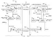
- the system 100may be implemented as a communication system used to move link status information through an optical or communications link which is normally considered to be 100% utilized, while generally having no impact on the normal data content or usefulness.
- the system 100may make use of otherwise dark (unused) fiber in a cable 102 to carry status and/or configuration information between circuits or modules 104 a–b .
- a low bandwidth of the status and/or configuration informationmay allow optical sources used to transmit the status and/or configuration information between the modules 104 a–b to be eye-safe, non-coherent light instead of a laser beam, and thus not constrained by normal laser safety requirements.
- Each module 104 a–bmay be implemented as a four-lane optical module.
- the modules 104 a–bmay comply with the 10 Gigabit Fibre Channel draft specification T11/Project 1413-D (published by the American National Standards Institute, New York, N.Y.), the InfiniBandTM Architecture specification (published by the InfiniBand Trade Association, Portland, Oreg.), or a Synchronous Optical Network (SONET) Very Short Reach (VSR) standard defined by the Optical Internetworking Forum (OIF) Implementation Agreement OIF-VSR4-03.0 (published by the Optical Internetworking Forum, Fremont, Calif.) hereby incorporated by reference in their entirety.
- the modules 104 a–bmay comply with other standards to meet the design criteria of a particular application.
- the cable 102may be implemented as a ribbon-fiber cable.
- the fiber cable 102may be terminated with connectors that comply with the Fibre Optic Connector Interfaces—Part 7: Type MPO Connector Family specification IEC 61754-7 (published by the International Electrotechnical Commission, Geneva, Switzerland) hereby incorporated by reference in its entirety.
- the fiber cable 102may have twelve strands or fibers.
- the fiber cable 102may have a length of up to 300 meters.
- the fiber cable 102may be implemented without introducing a twist between the modules 104 a–b .
- Other cable standardsmay be implemented to meet the design criteria of a particular application.
- the fiber cable 102generally comprises multiple physical channels 106 a–l .
- Each physical channel 106may be implemented as a multi-mode fiber optic strand.
- Each fiber optic strand 106may be a 50 micrometer ( ⁇ m) or a 62.5 ⁇ m multi-mode fiber.
- Other physical channels, such as coaxial cable, twisted wire pairs, transmission line, single mode fiber strand or the likemay be implemented to meet the design criteria of a particular application.
- the module 104 agenerally comprises a housing 108 a , a connector 110 a , multiple lasers 112 a–d , multiple photodetectors 114 a–d , a light emitting diode (LED) 116 a , and another photodetector 118 a .
- the module 104 bgenerally comprises a housing 108 b , a connector 110 b , multiple lasers 112 e–h , multiple photodetectors 114 e–h , an LED 116 b , and a photodetector 118 b .
- the fiber cable 102may be arranged to couple the lasers 112 and LED 116 of a module 104 to the photodetectors 114 and 118 of the other module 104 .
- the fiber optic strands 106 i–lmay couple the lasers 112 a–d to the photodetectors 114 e–h .
- the lasers 112 e–hmay be coupled through the fiber optic strands 106 a–d to the photodetectors 114 a–d .
- the fiber optic strand 106 fmay couple the LED 116 b to the photodetector 118 a .
- the fiber optic strand 106 gmay couple the LED 116 a to the photodetector 118 b .
- the fiber optic strands 106 e and 106 hmay be unused or dark fibers. In another embodiment, the fiber strands 106 e and 106 h may be used to couple the LEDs 116 and the photodetectors 118 while the fiber optic strands 106 f and 106 g may remain dark.
- the fiber cable 102may have as few as two fiber optic strands 106 .
- a first fiber optic strand 106 amay be provided for carrying user data from the module 104 b to the module 104 a .
- a second fiber optic strand 106 gmay be positioned for carrying a status signal from the module 104 a back to the module 104 b .
- other non-coherent and/or wide chromatic spectrum light sourcesmay be used in place of the LEDs 116 .
- the fiber cable 102may have four fiber optic strands 106 .
- a first fiber optic strand 106 dmay convey user data from the module 104 b to the module 104 a .
- a second fiber optic strand 106 gmay be provided for conveying status information from the module 104 a to the module 104 b .
- a third fiber optic strand 106 fmay be provided to carry additional status information from the module 104 b to the module 104 a .
- a fourth fiber optic strand 106 imay carry additional user data from the module 114 a to the module 104 b.
- a target use for the LEDs 116 and associated photodetectors 118may be to report link status and received laser power levels back to the laser sources (e.g., the modules 104 a–b ).
- the received laser power level informationgenerally allows the modules 104 a–b to adjust, optimize, and maintain laser power output levels as the lasers 112 and/or fiber optic strands 106 degrade with time.
- the received laser power level informationmay also be used to implement a laser safety interlock protocol to allow higher laser launch power while maintaining a class-1 laser safe environment.
- the two fiber optic strands 106 f/g or 106 e/hmay be implemented with alternate technology that could be lower in cost than the fiber optic strands 106 a–d and 106 i–l used to carry user data.
- FIG. 3a diagram of a multi-fiber connector 120 used for four-lane optical links is shown.
- Conventional 4-lane optical transceiverssuch as those specified by the 10 G Fibre Channel, the InfiniBandTM, and the OIF VSR specifications or standards, may all be implemented with a Multiple Parallel Optics (MPO) connector 120 .
- the MPO connector 120may be defined by the IEC standard 61754-7.
- the MPO connector 120generally has a twelve-fiber MT-type ferrule 122 connectable to the twelve-fiber ribbon cable 102 .
- the outer four fibers on each sidemay be active (e.g., marked with an “O”).
- the center four fiberse.g., numbered 4 , 5 , 6 , and 7
- Conventional fiber cables 102that may be used to interconnect the modules 104 a and 104 b may be built with all twelve fiber optic strands 106 a–l in place.
- the twelve fiber optic strands 106 a–lmay be fabricated because twelve-channel modules are also made and it generally costs manufacturers less to build and stock only twelve-fiber cables than to build and stock both eight-fiber and twelve-fiber cables.
- the normally dark fibers in the twelve-fiber cable 102may be used for low-speed signaling between the modules 104 a and 104 b .
- the low-speed signaling of status informationmay represent an inclusion of a normally out-of-band signaling function along fiber optic strands 106 that may already be present in the inter-module link.
- the low-speed signalingmay provide a separate inherently eye-safe link (e.g., light from the LEDs 116 ).
- the eye-safe linkmay be used to implement a laser safe link initialization protocol. Using a spectrally visible form of signaling as part of the eye-safe link generally allows the laser safe link initialization protocol to enhance user avoidance of potentially hazardous optical radiation.
- connectors 120 and cables 102may be used in other embodiments to meet the design criteria of particular applications.
- the connectors 120 and the cable 102may comply with a Mini-MT, a Mini-MPO, a 16MT, a 24MT, a 60MT, an 80MT, an MTP, an MT-RJ, an MT_BP design, an SMC connector or similar connector/cable interface types.
- Electrical or other non-optical type connectorsmay also be used in particular applications where the physical channels 106 are electrical or non-optical in nature.
- a mixture of optical and non-optical connections within a connector 120 and cable 102may also be used where the low-speed link may be non-optical and the user data links are optical.
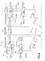
- the system 100may provide for one or two feedback or information loops for each laser 112 .
- a first information loopmay be established through the fiber cable 102 .
- Another information loopmay be established internal to each of the modules 104 a and 104 b.
- the module 104 amay include a controller 124 a , a memory 125 a , multiple laser drivers 126 a–d , and multiple transimpedance amplifiers 128 a–d .
- the laser drivers 126 a–dmay operate similarly to the laser drivers 126 e–h in the module 104 b , as described below, and thus are not shown within the module 104 a for clarity.
- the photodetectors 114 b–d and the associated transimpedance amplifiers 128 c–dare similar to the photodiode 114 a and the transimpedance amplifier 128 a and thus are not shown for clarity.
- the controller 124 amay be implemented as a micro controller, microprocessor, a state machine, or similar logic circuit.
- the module 104 bmay have similar components as the module 104 a.
- Each photodiode 114 a–dmay receive a signal OPT_DATA_ 0 – 3 from a respective fiber 106 a–d and convert the signal to a corresponding current.
- Each transimpedance amplifier 128 a–dmay receive the corresponding current from the respective photodiode 114 a–d .
- Each transimpedance amplifier 128 a–dmay generate a signal (e.g., RX_DATA_ 0 through RX_DATA_ 3 ) to transfer the received data.
- Each transimpedance amplifier 128 a–dmay also generate a signal (e.g., REC_PWR_A through REC_PWR_D) indicating an amount of optical power received by the photodiodes 114 a–d.
- the controller 124 amay be coupled to each of the transimpedance amplifiers 128 a–d to receive the signals REC_PWR_A–D.
- the controller 124 amay generate and present a signal (e.g., REC_STATUS) to the LED 116 a .
- the LED 116 amay convert the signal REC_STATUS from an electrical form into an optical form as another signal (e.g., OPT_STATUS).
- the module 104 bmay include a controller 124 b , a memory 125 b , multiple laser drivers 126 e–h (only the laser driver 126 e is shown for clarity), and multiple transimpedance amplifiers 128 e–h (not shown for clarity).
- the controller 124 bmay be similar to the controller 124 a in the module 104 a .
- the memory 125 bmay be an integrated part of the controller 124 b .
- the controller 124 bmay receive a signal (e.g., STATUS) from the photodiode 118 b .
- a signal(e.g., PARAM) may be received by the controller 124 b from the memory 125 b .
- the controller 124 bmay generate and present a signal (e.g., CNT_x, where E ⁇ x ⁇ H) to each of the respective laser drivers 136 e–h .
- the controller 124 bmay generate and present an enable signal (e.g., LSR_EN_x, where E ⁇ x ⁇ H) to each of the respective laser drivers 136 e–h .
- a signal(e.g., USER_STATUS) may be generated and/or received by the controller 124 b through a bi-directional connection.
- Each laser driver 126 e–hmay receive electrical power (e.g., POWER) for operating the respective lasers 112 e–h .
- Each laser driver 126 e–hmay also receive a signal (e.g., TX_DATA_ 0 through TX_DATA_ 3 ) from a host system (not shown) that may be a source of the data streams conveying user data sent across the fiber optic link.
- Each laser driver 126 e–hmay generate and provide a modulated current signal (e.g., LSR_E through LSR_H) to the respective lasers 112 e–h .
- Each laser driver 126 e–hmay also generate and provide a signal (e.g., CUR_MON_x, where E ⁇ x ⁇ H) to the controller 124 b.
- the lasers 112may be implemented as vertical cavity surface emitting lasers (VCSEL). Other types of lasers may be used in a particular design to meet the criteria of a particular application.
- Each laser 112 e–hmay convert the signal LSR_x to a respective optical signal (e.g., OPT_DATA_y, where 0 ⁇ y ⁇ 3). Only the optical signal OPT_DATA_ 0 is shown for clarity.
- a combination of each laser 112 and a respective laser driver 126may also be referred to as a transmitter 130 e–h .
- the photodetectors 114 a–d and the transimpedance amplifiers 128 a–d in the module 104 amay receive, detect, and convert the optical signal OPT_DATA_ 0 – 3 into the respective signals REC_PWR_A–D.
- a combination of each photodiode 114 and a respective transimpedance amplifier 128may also be referred to as a receiver 129 .
- the signals REC_PWRmay be implemented as electrical signals. Each signal REC_PWR may convey information about an amount of optical power received by a photodetector 114 . Each signal REC_PWR may be independent of other signals REC_PWR.
- the signal REC_STATUSmay be implemented as an electrical signal.
- the signal REC_STATUSmay time division multiplex the received power information from signals REC_PWR.
- Other informationmay be multiplexed into the signal REC_STATUS for transfer to the module 104 b .
- the signals USER_STATUSmay be used to transfer other information between the controllers 124 a and 124 b .
- the other informationmay include, but may not be limited to voltage, temperature, operational state and so forth.
- the signal OPT_STATUSmay be implemented as an optical signal.
- the signal OPT_STATUSmay be implemented as a non-coherent optical signal.
- the signal OPT_STATUSmay be visible to a human eye, although the signal OPT_STATUS may be infrared or another invisible wavelength.
- the signal OPT_STATUSmay convey information from the module 104 a to the module 104 b equivalent to the information generated by the controller 124 a in the signal REC_STATUS.
- the signal OPT_STATUSmay be considered to be an out-of-band signal that may not normally be part of a standard communication protocol used between the modules 104 a and 104 b.
- the signal STATUSmay be implemented as an electrical status signal.
- the signal STATUSmay convey the same information as the optical signal OPT_STATUS.
- the signal STATUSmay therefore convey the same information as the signal REC_STATUS.
- the signal PARAMmay be implemented as an electrical signal.
- the signal PARAMmay provide lookup table type information to the controller 124 b for converting feedback values in the signals CUR_MON and/or STATUS into appropriate control values in the signals CNT and LSR_EN.
- the signals CNTmay be implemented as electrical control signals. Each signal CNT may provide instructions to a respective laser driver 126 regarding how much optical power the associated laser 112 should generate. Each signal CNT_A–H may be uniquely generated for each laser driver 126 /laser 112 pair.
- the signals TX_DATA and RX_DATAmay be implemented as one or more electrical data signals.
- the signals TX_DATAmay carry information from a user or client to be transmitted from a sending module 104 to a receiving module 104 .
- the signals RX_DATAmay represent received versions of the signals TX_DATA at the receiving module 104 . Audio, visual, files, data streams, and other forms of user data may be provided to the transmitters 130 by the signals TX_DATA.
- Each signal TX_DATA and the corresponding signal RX_DATAmay convey some or all of the user information depending upon a particular application.
- the signals TX_DATA_ 0 – 3may each carry every fourth bit of the user data in parallel simultaneously.
- the signal TX_DATA_ 0may carry all of the information provided by a first user
- the signal TX_DATA_ 1may carry all of the information provided by a second user
- the signal TX_DATA_ 2may carry all of the information provided by a third user
- the signal TX_DATA_ 3may carry all of the information provided by a fourth user.
- Other arrangements of the user data among the signals TX_DATA_ 0 – 3may be implemented to meet the design criteria of a particular application.
- the signals LSR_ENmay be implemented as electrical signals. Each signal LSR_EN may have an enable state to enable a respective transmitter 130 . Each signal LSR_EN may have a disable state to disable the respective transmitter 130 .
- the signals CUR_MONmay be implemented as electrical power or current utilization feedback signals from the laser driver 126 .
- Each signal CUR_MONmay provide the controller 124 b with an indication of how much electrical current may be provided to the respective laser 112 .
- the controller 124 bmay use the data in the signals CUR_MON to control the signals LSR_EN.
- the signals LSRmay be implemented as electrical signals.
- the signals LSRmay be generated by the laser drivers 126 to drive or power the individual lasers 112 .
- Each signal LSRmay also carry some or all of the user data as defined by the respective signal TX_DATA.
- the signals OPT_DATAmay be implemented as infrared optical signals. In one embodiment, the signals OPT_DATA may be implemented as narrow spectral width laser light. The signals OPT_DATA may be modulated to transfer the user data provided in the signals LSR.
- the host systemmay distribute the user data among the signal TX_DATA_ 0 through TX_DATA_ 3 for transmission across the fiber cable 102 .
- Each transmitter 130 e–hmay convert the information in the signals TX_DATA_ 0 – 3 into the laser signals OPT_DATA_ 0 – 3 that are then transmitted to the module 104 a .
- the module 104 amay monitor the amount of optical power received by each photodiode 114 a–d and provide feedback of what was actually received to the module 104 b via the signal OPT_STATUS.
- the controller 124 b within the module 104 bmay then adjust the signals CNT_E–H to adjust each individual transmitter 130 e–h based upon the feedback received in the signal STATUS.
- Long information loopsare generally established from the controller 124 b through the transmitters 130 e–h , the fiber optic strands 106 a–d , the photodiodes 114 a–d , transimpedance amplifiers 128 a–d , the controller 124 a , the LED 116 a , the fiber optic strand 106 g , the photodiode 118 b , and back to the controller 124 b .
- the controller 124 bmay operate the lasers 112 e–h at generally less than maximum power and therefore extend the life of the lasers 112 e–h .
- a similar benefitmay be achieved for the lasers 112 a–d by monitoring the amount of laser light received at the module 104 b and then feeding the information back to the module 104 a.
- a short information loopmay be established inside each module 104 a and 104 b .
- the signals CUR_MON_E through CUR_MON_Hmay be processed by the controller 124 b to determine in part the signals LSR_EN_E through LSR_EN_H provided to the laser drivers 126 e–h .
- the short feedback loopis generally not directly translated into optical output power since a conversion efficiency of the lasers 112 may not be a constant and may vary with temperature and usage life of the lasers 112 . Therefore, the short information loop is generally used for fault detection and shut-down in the event that one or more of the lasers 112 sink too much or too little current.
- LEDs 116 a–bBy using standard LEDs 116 a–b as optical sources (preferably having an optical emission within in the visible spectrum), low-bandwidth links between the two optical modules 104 a and 104 b may be established.
- the modules 104 a–b and fiber cable 102are generally implemented with multi-mode fiber and thus may be capable of carrying light from the LEDs 116 a–b without difficulty.
- Each LED 116 a–bgenerally has a very wide launch angle (a numerical aperture) and may be spectrally impure. Therefore, the LEDs 116 a–b are generally unusable for the high-speed signaling performed for the user data.
- the optical characteristics of the LEDs 116 a–bare inherently eye-safe and are free of eye safety restrictions that may be imposed on the lasers 112 a–h.
- the LED 116 and photodetector 118 pairsare generally very low cost items and (unlike the photodetectors 114 and the VCSELs 112 or other semiconductor lasers) may have flexible drive constraints. Driving the LEDs 116 with current may cause a light emission. Removing the current from the LEDs 116 results in no light emission or darkness. In contrast, a semiconductor laser is generally never fully turned off in normal operation. Instead, a light output of a semiconductor laser may be modulated between a high output level and a low output level. Furthermore, the recovery mechanism for the VCSELs 112 generally include high-performance photodetectors 114 and transimpedance amplifiers 128 connected to a phase lock loop (not shown) for clock and data extraction.
- the LEDs 116may be directly driven and monitored from the controllers 124 using only a few milliamps of current.
- the signaling rate of a low-cost LEDmay still provide hundreds of kilobits per second. While hundreds of kilobits per second may be insufficient for user data communications, the hundreds of kilobits per second are generally more than enough for link maintenance.
- a time span to bring up a link using conventional laser safety interlockscan exceed ten seconds, during which over a megabit of configuration data may be transfer between the modules 104 via the low-speed links.
- the LED 116 /photodetector 118 pairmay be located on either fiber optic strands 106 e and 106 h (numbers 4 and 7 ) or on the fiber optic strands 106 f and 106 g (numbers 5 and 6 ).
- the order of LEDs 116 and detectors 118may also be reversed from that shown in FIG. 2 .
- the wavelength of the optical sourcemay be anything supported by the detectors 118 and the fiber cable 102 , however, a wavelength in the visible region (e.g., 532 nm) may allow for a visual indication of power and state of the modules 104 a–b .
- a low-rate of on/off signalingmay be directly noticeable to a human observer and thus may be used to indicate that the link could not initialize.
- a different flashing rate or a predetermined flashing codemay indicate that one or more failures have been detected.
- a high modulation ratee.g., >100 bits per second
- the LEDs 116 , and the photodetectors 118may not be in any particular proximity to the high-speed lasers 112 and/or the detectors 114 .
- the LEDs 116 and the photodetectors 118may be contained in a remote section of the housing 108 . Small sections of large core fibers 132 a–b may be embedded between the connector ferrules 122 a–b and the LEDs 116 and the photodetectors 118 to provide for communications externally to the modules 104 a–b.
- Operationgenerally begins with applying power to the modules 104 (e.g., block 134 ).
- the power up sequencemay include checking the fiber cable 102 by establishing communications between the controllers 124 using the low-speed link LEDs 116 and the photodetectors 118 . While establishing the communications on the low-speed links, the controllers 124 may modulate the LEDs 116 to cause the visible signals OPT_STATUS to flash or blink in a predetermined and observable pattern and/or frequency.
- the controllers 124may make use of the signals OPT_STATUS for establishing communications (e.g., decision block 140 ). If the process of establishing communications does not successfully complete (e.g., the NO branch of the decision block 140 ), the controllers 124 may continue to modulate the LEDs 116 to flash an initialization code (e.g., block 138 ). Where communications between the modules 104 cannot be established, the power up sequence may end without energizing the lasers 112 .
- each controller 124may monitor for the signal OPT_STATUS from the other module 104 (e.g., decision block 140 ). If no communication has been established (e.g., the NO branch of decision block 140 ), the controllers 124 generally continue to attempt to establish communications. When communication has been established (e.g., the YES branch of decision block 140 ), the controllers 124 may exchange initialization information with each other (e.g., block 142 ). While the modules 104 are initializing, the controllers 124 may modulate the LEDs 116 to flash in an initialization pattern.
- the controllers 124may exchange initialization information with each other (e.g., block 142 ). While the modules 104 are initializing, the controllers 124 may modulate the LEDs 116 to flash in an initialization pattern.
- the module 104may complete initialization by enabling the lasers 112 for minimal power (e.g., block 142 ) and change the LED 116 modulation pattern to appear as another pattern.
- the modulation patternmay indicate a continuous monitoring of the local photodetector 114 power status (e.g., block 148 ) and transmission of that status as OPT_STATUS (e.g., block 150 ).
- a module 104may receive user data from the fiber cable 102 .
- the photodetectors 114 , transimpedance amplifiers 128 , and controller 124 in the receiving module 104may determine the power levels of the signals OPT_DATA received on each fiber optic strand 106 to generate status data (e.g., block 148 ). The controller 124 of the receiving module 104 may then transmit the status data back to the sending module 104 via the signal OPT_STATUS (e.g., block 150 ) and capture a new received power level for transmission as the next signal OPT_STATUS.
- OPT_STATUSe.g., block 150
- the lasers 112may be enabled (e.g., block 142 ) and the modules 104 may begin to exchange status information (e.g., blocks 144 and 150 ). Once status has been received, the modules 104 are generally in communication and may remain eye-safe, regardless of the presented laser power. Because all fibers 106 in the cable 102 must be fully inserted in the receptacles 110 of both modules 104 to allow the initialize sequence to be received, all light generated by the lasers 112 in one module 104 is generally delivered only to the photodetectors 114 in the alternate module 104 .
- Each module 104may thereafter continuously monitor for reception of the signal OPT_STATUS (e.g., decision block 144 ). If the signal OPT_STATUS has not been received recently (e.g., the NO branch of decision block 144 ), the controller 124 may immediately disable the associated lasers 112 (e.g., block 152 ), stop sending local received power status, and attempt to re-initialize the link.
- the lack of OPT_STATUSis generally an indication of either a module fault at the remote module 104 or a break in the fiber which could result in a non-eye-safe laser light condition if the lasers 112 remained enabled.
- the controller 124may use the status information provided by the receiving module 104 to adjust the laser power of the local lasers 112 (e.g., block 146 ). If at any time a local fault is detected within the module 104 (e.g., over or under temperature, over or under voltage, excess laser current, local disable, or the like), the local lasers 112 may all be immediately disabled, regardless of a previous state within the start-up protocol (e.g., block 154 ).
- the controller 124may modulate the local LED 116 to cause the visible signal OPT_STATUS to flash or blink in a predetermined and observable pattern and/or frequency (e.g., block 156 ), with the pattern or frequency being significantly different from the initialize pattern or frequency.
- a local faulte.g., the YES branch of decision block 136
- the controller 124may modulate the local LED 116 to cause the visible signal OPT_STATUS to flash or blink in a predetermined and observable pattern and/or frequency (e.g., block 156 ), with the pattern or frequency being significantly different from the initialize pattern or frequency.
- the controllers 124may treat the four local lasers 112 as one or more groups. Therefore, adjustments to the laser output power may be made to multiple lasers substantially simultaneously. Likewise, collection of the power actually received by the photodetectors 114 may be processed by the receiving controller 124 to determine a single status data for each laser group.
- the short feedback loop within the modules 104may be eliminated. The short feedback loop may be undesirable where, for example, a laser driver 126 may compensate for changes in a laser 112 and/or major changes in current.
- the modulation of the LEDs 116may include a dark or zero percent duty cycle modulation.
- the modules 104may include a “watchdog” circuit (not shown) that may switch off the lasers 112 and the LEDs 116 in case of a failure in the controller 124 . Therefore, an absence of visible light from a module 104 may indicate that the module 104 may be off or that a catastrophic failure may have occurred.
- a “watchdog” circuitnot shown
- the various signals of the present inventionmay be implemented as single-bit or multi-bit signals in a serial and/or parallel configuration.
- the term “simultaneously”is meant to describe events that share some common time period but the term is not meant to be limited to events that begin at the same point in time, end at the same point in time, or have the same duration.
Landscapes
- Physics & Mathematics (AREA)
- Electromagnetism (AREA)
- Engineering & Computer Science (AREA)
- Computer Networks & Wireless Communication (AREA)
- Signal Processing (AREA)
- Optical Communication System (AREA)
Abstract
Description
Claims (20)
Priority Applications (1)
| Application Number | Priority Date | Filing Date | Title |
|---|---|---|---|
| US10/183,812US7062177B1 (en) | 2002-06-25 | 2002-06-25 | Out of band communications link for 4-lane optical modules using dark fibers and low-bandwidth LEDs |
Applications Claiming Priority (1)
| Application Number | Priority Date | Filing Date | Title |
|---|---|---|---|
| US10/183,812US7062177B1 (en) | 2002-06-25 | 2002-06-25 | Out of band communications link for 4-lane optical modules using dark fibers and low-bandwidth LEDs |
Publications (1)
| Publication Number | Publication Date |
|---|---|
| US7062177B1true US7062177B1 (en) | 2006-06-13 |
Family
ID=36576574
Family Applications (1)
| Application Number | Title | Priority Date | Filing Date |
|---|---|---|---|
| US10/183,812Expired - Fee RelatedUS7062177B1 (en) | 2002-06-25 | 2002-06-25 | Out of band communications link for 4-lane optical modules using dark fibers and low-bandwidth LEDs |
Country Status (1)
| Country | Link |
|---|---|
| US (1) | US7062177B1 (en) |
Cited By (67)
| Publication number | Priority date | Publication date | Assignee | Title |
|---|---|---|---|---|
| US20040008990A1 (en)* | 2002-06-27 | 2004-01-15 | Hitoshi Uno | Station side apparatus, subscriber side apparatus and optically communicating system apparatus |
| US20040076166A1 (en)* | 2002-10-21 | 2004-04-22 | Patenaude Jean-Marc Guy | Multi-service packet network interface |
| US20050019041A1 (en)* | 2003-06-25 | 2005-01-27 | Daimlerchrysler Ag | Detection of optical light power |
| US20060110160A1 (en)* | 2002-08-06 | 2006-05-25 | Eric Hoedt | Method and device for the transmission of information by means of an optical data transmission system |
| US20060198635A1 (en)* | 2005-03-04 | 2006-09-07 | Emery Clayton J | Optical network terminal with illegal transmission detection circuitry |
| US20070009266A1 (en)* | 2005-07-07 | 2007-01-11 | Andrew Bothwell | Multimode optical fibre communication system |
| US20080025676A1 (en)* | 2004-10-15 | 2008-01-31 | Emcore Corporation | Laser Adjustment in Integrated Optoelectronic Modules/Fiber Optic Cables |
| US20080247752A1 (en)* | 2007-04-05 | 2008-10-09 | Emcore Corp. | Eye safety in electro-optical transceivers |
| US20100316374A1 (en)* | 2009-06-15 | 2010-12-16 | Fiber Connections Inc. | Networked mapping function |
| US20120093518A1 (en)* | 2010-10-13 | 2012-04-19 | Cisco Technology, Inc. | Single package bidirectional module for multimode fiber communication |
| US20130223484A1 (en)* | 2012-02-23 | 2013-08-29 | Cisco Technology, Inc. | Two-Channel Compact Small Form-Factor Pluggable Module |
| WO2013147754A1 (en)* | 2012-03-27 | 2013-10-03 | Intel Corporation | Optical link handshake techniques and configurations |
| US20130315586A1 (en)* | 2012-05-23 | 2013-11-28 | Brocade Communications Systems, Inc. | Terabit top-of-rack switch |
| US20150093073A1 (en)* | 2013-09-30 | 2015-04-02 | Anue Systems, Inc. | Optical Tap Modules Having Integrated Splitters And Aggregated Multi-Fiber Tap Output Connectors |
| US20160028487A1 (en)* | 2014-07-25 | 2016-01-28 | Futurewei Technologies, Inc. | Compensation of Non-Linear Transmitter Impairments in Optical Communication Networks |
| WO2016153899A1 (en)* | 2015-03-20 | 2016-09-29 | Oracle International Corporation | Safety-enhanced laser array |
| US9548873B2 (en) | 2014-02-10 | 2017-01-17 | Brocade Communications Systems, Inc. | Virtual extensible LAN tunnel keepalives |
| US9565099B2 (en) | 2013-03-01 | 2017-02-07 | Brocade Communications Systems, Inc. | Spanning tree in fabric switches |
| US9608833B2 (en) | 2010-06-08 | 2017-03-28 | Brocade Communications Systems, Inc. | Supporting multiple multicast trees in trill networks |
| US9628293B2 (en) | 2010-06-08 | 2017-04-18 | Brocade Communications Systems, Inc. | Network layer multicasting in trill networks |
| US9628336B2 (en) | 2010-05-03 | 2017-04-18 | Brocade Communications Systems, Inc. | Virtual cluster switching |
| US9626255B2 (en) | 2014-12-31 | 2017-04-18 | Brocade Communications Systems, Inc. | Online restoration of a switch snapshot |
| US9628407B2 (en) | 2014-12-31 | 2017-04-18 | Brocade Communications Systems, Inc. | Multiple software versions in a switch group |
| US20170170993A1 (en)* | 2015-12-08 | 2017-06-15 | Zte Corporation | Training assisted joint equalization |
| US9699117B2 (en) | 2011-11-08 | 2017-07-04 | Brocade Communications Systems, Inc. | Integrated fibre channel support in an ethernet fabric switch |
| US9699029B2 (en) | 2014-10-10 | 2017-07-04 | Brocade Communications Systems, Inc. | Distributed configuration management in a switch group |
| US9716672B2 (en) | 2010-05-28 | 2017-07-25 | Brocade Communications Systems, Inc. | Distributed configuration management for virtual cluster switching |
| US9736085B2 (en) | 2011-08-29 | 2017-08-15 | Brocade Communications Systems, Inc. | End-to end lossless Ethernet in Ethernet fabric |
| US9742693B2 (en) | 2012-02-27 | 2017-08-22 | Brocade Communications Systems, Inc. | Dynamic service insertion in a fabric switch |
| US9769016B2 (en) | 2010-06-07 | 2017-09-19 | Brocade Communications Systems, Inc. | Advanced link tracking for virtual cluster switching |
| US9774543B2 (en) | 2013-01-11 | 2017-09-26 | Brocade Communications Systems, Inc. | MAC address synchronization in a fabric switch |
| US9800471B2 (en) | 2014-05-13 | 2017-10-24 | Brocade Communications Systems, Inc. | Network extension groups of global VLANs in a fabric switch |
| US9807007B2 (en) | 2014-08-11 | 2017-10-31 | Brocade Communications Systems, Inc. | Progressive MAC address learning |
| US9806906B2 (en) | 2010-06-08 | 2017-10-31 | Brocade Communications Systems, Inc. | Flooding packets on a per-virtual-network basis |
| US9807031B2 (en) | 2010-07-16 | 2017-10-31 | Brocade Communications Systems, Inc. | System and method for network configuration |
| US9807017B2 (en) | 2013-01-11 | 2017-10-31 | Brocade Communications Systems, Inc. | Multicast traffic load balancing over virtual link aggregation |
| US9807005B2 (en) | 2015-03-17 | 2017-10-31 | Brocade Communications Systems, Inc. | Multi-fabric manager |
| US9848040B2 (en) | 2010-06-07 | 2017-12-19 | Brocade Communications Systems, Inc. | Name services for virtual cluster switching |
| US9887916B2 (en) | 2012-03-22 | 2018-02-06 | Brocade Communications Systems LLC | Overlay tunnel in a fabric switch |
| US9912612B2 (en) | 2013-10-28 | 2018-03-06 | Brocade Communications Systems LLC | Extended ethernet fabric switches |
| US9912614B2 (en) | 2015-12-07 | 2018-03-06 | Brocade Communications Systems LLC | Interconnection of switches based on hierarchical overlay tunneling |
| US9942097B2 (en) | 2015-01-05 | 2018-04-10 | Brocade Communications Systems LLC | Power management in a network of interconnected switches |
| US9989167B2 (en)* | 2015-03-02 | 2018-06-05 | Dresser, Inc. | Valve positioner communication method and apparatus |
| US10003552B2 (en) | 2015-01-05 | 2018-06-19 | Brocade Communications Systems, Llc. | Distributed bidirectional forwarding detection protocol (D-BFD) for cluster of interconnected switches |
| US10038592B2 (en) | 2015-03-17 | 2018-07-31 | Brocade Communications Systems LLC | Identifier assignment to a new switch in a switch group |
| US20180239100A1 (en)* | 2012-10-05 | 2018-08-23 | Commscope Asia Holdings B.V. | Flexible optical circuit, cassettes, and methods |
| US10063473B2 (en) | 2014-04-30 | 2018-08-28 | Brocade Communications Systems LLC | Method and system for facilitating switch virtualization in a network of interconnected switches |
| US10148363B2 (en) | 2015-12-08 | 2018-12-04 | Zte Corporation | Iterative nonlinear compensation |
| US10164883B2 (en) | 2011-11-10 | 2018-12-25 | Avago Technologies International Sales Pte. Limited | System and method for flow management in software-defined networks |
| US10171303B2 (en) | 2015-09-16 | 2019-01-01 | Avago Technologies International Sales Pte. Limited | IP-based interconnection of switches with a logical chassis |
| US10237090B2 (en) | 2016-10-28 | 2019-03-19 | Avago Technologies International Sales Pte. Limited | Rule-based network identifier mapping |
| US10277464B2 (en) | 2012-05-22 | 2019-04-30 | Arris Enterprises Llc | Client auto-configuration in a multi-switch link aggregation |
| US10439929B2 (en) | 2015-07-31 | 2019-10-08 | Avago Technologies International Sales Pte. Limited | Graceful recovery of a multicast-enabled switch |
| US10476698B2 (en) | 2014-03-20 | 2019-11-12 | Avago Technologies International Sales Pte. Limited | Redundent virtual link aggregation group |
| US10581758B2 (en) | 2014-03-19 | 2020-03-03 | Avago Technologies International Sales Pte. Limited | Distributed hot standby links for vLAG |
| US10579406B2 (en) | 2015-04-08 | 2020-03-03 | Avago Technologies International Sales Pte. Limited | Dynamic orchestration of overlay tunnels |
| US10616108B2 (en) | 2014-07-29 | 2020-04-07 | Avago Technologies International Sales Pte. Limited | Scalable MAC address virtualization |
| US10805005B2 (en) | 2018-11-16 | 2020-10-13 | Rolls-Royce Corporation | Frequency spectrum system security |
| US10873496B1 (en)* | 2018-09-10 | 2020-12-22 | Facebook, Inc. | Apparatuses, systems, and methods for link status detection and remediation of network attached devices |
| US11045900B2 (en)* | 2010-07-09 | 2021-06-29 | General Lasertronics Corporation | Coating ablating apparatus with coating removal detection |
| US11212001B1 (en) | 2020-11-20 | 2021-12-28 | International Business Machines Corporation | Transmit optical power adjustment based on receive optical power measurements |
| CN114301533A (en)* | 2020-10-08 | 2022-04-08 | 广达电脑股份有限公司 | Systems and methods for safe handling of optical assemblies and optical switches |
| US11338391B2 (en) | 2012-02-28 | 2022-05-24 | General Lasertronics Corporation | Laser ablation for the environmentally beneficial removal of surface coatings |
| US11372165B2 (en) | 2011-09-12 | 2022-06-28 | Commscope Technologies Llc | Flexible lensed optical interconnect device for signal distribution |
| US11409068B2 (en) | 2017-10-02 | 2022-08-09 | Commscope Technologies Llc | Fiber optic circuit and preparation method |
| US11592628B2 (en) | 2012-09-28 | 2023-02-28 | Commscope Technologies Llc | Fiber optic cassette |
| US12339511B2 (en) | 2020-03-31 | 2025-06-24 | Commscope Technologies Llc | Fiber optic cable management systems and methods |
Citations (8)
| Publication number | Priority date | Publication date | Assignee | Title |
|---|---|---|---|---|
| US4642804A (en)* | 1985-05-10 | 1987-02-10 | Bell Communications Research, Inc. | Shared laser lightwave transmission systems |
| US4994675A (en)* | 1989-04-28 | 1991-02-19 | Rebo Research, Inc. | Method and apparatus for checking continuity of optic transmission |
| US5136410A (en)* | 1990-01-09 | 1992-08-04 | Ibm Corporation | Optical fiber link control safety system |
| US5432874A (en)* | 1993-02-17 | 1995-07-11 | Sony Corporation | Duplex optical fiber link |
| US5615033A (en)* | 1994-09-27 | 1997-03-25 | Fujitsu Limited | Optical signal transmission apparatus and method |
| US5801860A (en)* | 1995-08-08 | 1998-09-01 | Nec Corporation | Wavelength division multiplexing transmission system comprising a feedback section for transmitting a light power level signal from a light receiver to a light transmitter |
| US6246499B1 (en)* | 1996-07-19 | 2001-06-12 | Sony Corporation | Optical signal communication apparatus and optical signal communication method |
| US6738584B1 (en)* | 1998-07-08 | 2004-05-18 | Fujitsu Ltd. | Method for optical fiber communication, and terminal device and system for use in carrying out the method |
- 2002
- 2002-06-25USUS10/183,812patent/US7062177B1/ennot_activeExpired - Fee Related
Patent Citations (8)
| Publication number | Priority date | Publication date | Assignee | Title |
|---|---|---|---|---|
| US4642804A (en)* | 1985-05-10 | 1987-02-10 | Bell Communications Research, Inc. | Shared laser lightwave transmission systems |
| US4994675A (en)* | 1989-04-28 | 1991-02-19 | Rebo Research, Inc. | Method and apparatus for checking continuity of optic transmission |
| US5136410A (en)* | 1990-01-09 | 1992-08-04 | Ibm Corporation | Optical fiber link control safety system |
| US5432874A (en)* | 1993-02-17 | 1995-07-11 | Sony Corporation | Duplex optical fiber link |
| US5615033A (en)* | 1994-09-27 | 1997-03-25 | Fujitsu Limited | Optical signal transmission apparatus and method |
| US5801860A (en)* | 1995-08-08 | 1998-09-01 | Nec Corporation | Wavelength division multiplexing transmission system comprising a feedback section for transmitting a light power level signal from a light receiver to a light transmitter |
| US6246499B1 (en)* | 1996-07-19 | 2001-06-12 | Sony Corporation | Optical signal communication apparatus and optical signal communication method |
| US6738584B1 (en)* | 1998-07-08 | 2004-05-18 | Fujitsu Ltd. | Method for optical fiber communication, and terminal device and system for use in carrying out the method |
Non-Patent Citations (5)
| Title |
|---|
| "Fibre Channel-10 Gigabit (10GFC)", Rev. 2.0, American National Standards Institute, Dec. 20, 2001, pp. 1-88, New York, New York. |
| "Fibre optic connector interfaces-Part 7: Type MPO connector family", (Edition 1:1996 consolidated with amendments 1:1999 and 2:2000), International Electrotechnical Commission, Nov. 2000, pp. 1-29, Geneva, Switzerland. |
| "InfiniBand(TM) Architecture Specification vol. 1", Release 1.0.a, InfiniBand<SUP>SM</SUP> Trade Association, Jun. 19, 2001, pp. 1-2, 124-194. |
| "InfiniBand(TM) Architecture Specification vol. 2", Release 1.0.a, InfiniBand<SUP>SM</SUP> Trade Association, Jun. 19, 2001, pp. 1-2, 49-131, 180-224. |
| "Very Short Reach (VSR) OC-192 four fiber Interface Based on Parallel Optics",Optical Internetworking Forum, Aug. 17, 2000, pp. 1-14, Fremont, California. |
Cited By (107)
| Publication number | Priority date | Publication date | Assignee | Title |
|---|---|---|---|---|
| US20040008990A1 (en)* | 2002-06-27 | 2004-01-15 | Hitoshi Uno | Station side apparatus, subscriber side apparatus and optically communicating system apparatus |
| US20060110160A1 (en)* | 2002-08-06 | 2006-05-25 | Eric Hoedt | Method and device for the transmission of information by means of an optical data transmission system |
| US20040076166A1 (en)* | 2002-10-21 | 2004-04-22 | Patenaude Jean-Marc Guy | Multi-service packet network interface |
| US20050019041A1 (en)* | 2003-06-25 | 2005-01-27 | Daimlerchrysler Ag | Detection of optical light power |
| US7460791B2 (en)* | 2003-06-26 | 2008-12-02 | Daimler Ag | Detection of optical light power |
| US20080025676A1 (en)* | 2004-10-15 | 2008-01-31 | Emcore Corporation | Laser Adjustment in Integrated Optoelectronic Modules/Fiber Optic Cables |
| US7581891B2 (en)* | 2004-10-15 | 2009-09-01 | Emcore Corporation | Laser adjustment in integrated optoelectronic modules/fiber optic cables |
| US20060198635A1 (en)* | 2005-03-04 | 2006-09-07 | Emery Clayton J | Optical network terminal with illegal transmission detection circuitry |
| US7424221B2 (en)* | 2005-03-04 | 2008-09-09 | Tellabs Petaluma, Inc. | Optical network terminal with illegal transmission detection circuitry |
| US7680421B2 (en)* | 2005-07-07 | 2010-03-16 | Avago Technologies General Ip (Singapore) Pte. Ltd. | Multimode optical fibre communication system |
| US20070009266A1 (en)* | 2005-07-07 | 2007-01-11 | Andrew Bothwell | Multimode optical fibre communication system |
| US20080247752A1 (en)* | 2007-04-05 | 2008-10-09 | Emcore Corp. | Eye safety in electro-optical transceivers |
| US7787767B2 (en)* | 2007-04-05 | 2010-08-31 | Emcore Corporation | Eye safety in electro-optical transceivers |
| US20100316374A1 (en)* | 2009-06-15 | 2010-12-16 | Fiber Connections Inc. | Networked mapping function |
| US9628336B2 (en) | 2010-05-03 | 2017-04-18 | Brocade Communications Systems, Inc. | Virtual cluster switching |
| US10673703B2 (en) | 2010-05-03 | 2020-06-02 | Avago Technologies International Sales Pte. Limited | Fabric switching |
| US9716672B2 (en) | 2010-05-28 | 2017-07-25 | Brocade Communications Systems, Inc. | Distributed configuration management for virtual cluster switching |
| US9942173B2 (en) | 2010-05-28 | 2018-04-10 | Brocade Communications System Llc | Distributed configuration management for virtual cluster switching |
| US10924333B2 (en) | 2010-06-07 | 2021-02-16 | Avago Technologies International Sales Pte. Limited | Advanced link tracking for virtual cluster switching |
| US9769016B2 (en) | 2010-06-07 | 2017-09-19 | Brocade Communications Systems, Inc. | Advanced link tracking for virtual cluster switching |
| US11757705B2 (en) | 2010-06-07 | 2023-09-12 | Avago Technologies International Sales Pte. Limited | Advanced link tracking for virtual cluster switching |
| US11438219B2 (en) | 2010-06-07 | 2022-09-06 | Avago Technologies International Sales Pte. Limited | Advanced link tracking for virtual cluster switching |
| US9848040B2 (en) | 2010-06-07 | 2017-12-19 | Brocade Communications Systems, Inc. | Name services for virtual cluster switching |
| US10419276B2 (en) | 2010-06-07 | 2019-09-17 | Avago Technologies International Sales Pte. Limited | Advanced link tracking for virtual cluster switching |
| US9806906B2 (en) | 2010-06-08 | 2017-10-31 | Brocade Communications Systems, Inc. | Flooding packets on a per-virtual-network basis |
| US9608833B2 (en) | 2010-06-08 | 2017-03-28 | Brocade Communications Systems, Inc. | Supporting multiple multicast trees in trill networks |
| US9628293B2 (en) | 2010-06-08 | 2017-04-18 | Brocade Communications Systems, Inc. | Network layer multicasting in trill networks |
| US20210308788A1 (en)* | 2010-07-09 | 2021-10-07 | General Lasertronics Corporation | Coating ablating apparatus with coating removal detection |
| US11045900B2 (en)* | 2010-07-09 | 2021-06-29 | General Lasertronics Corporation | Coating ablating apparatus with coating removal detection |
| US20240082947A1 (en)* | 2010-07-09 | 2024-03-14 | General Lasertronics Corporation | Coating ablating apparatus with coating removal detection |
| US11819939B2 (en)* | 2010-07-09 | 2023-11-21 | General Lasertronics Corporation | Coating ablating apparatus with coating removal detection |
| US10348643B2 (en) | 2010-07-16 | 2019-07-09 | Avago Technologies International Sales Pte. Limited | System and method for network configuration |
| US9807031B2 (en) | 2010-07-16 | 2017-10-31 | Brocade Communications Systems, Inc. | System and method for network configuration |
| US20120093518A1 (en)* | 2010-10-13 | 2012-04-19 | Cisco Technology, Inc. | Single package bidirectional module for multimode fiber communication |
| US9736085B2 (en) | 2011-08-29 | 2017-08-15 | Brocade Communications Systems, Inc. | End-to end lossless Ethernet in Ethernet fabric |
| US11372165B2 (en) | 2011-09-12 | 2022-06-28 | Commscope Technologies Llc | Flexible lensed optical interconnect device for signal distribution |
| US9699117B2 (en) | 2011-11-08 | 2017-07-04 | Brocade Communications Systems, Inc. | Integrated fibre channel support in an ethernet fabric switch |
| US10164883B2 (en) | 2011-11-10 | 2018-12-25 | Avago Technologies International Sales Pte. Limited | System and method for flow management in software-defined networks |
| US20130223484A1 (en)* | 2012-02-23 | 2013-08-29 | Cisco Technology, Inc. | Two-Channel Compact Small Form-Factor Pluggable Module |
| US8831432B2 (en)* | 2012-02-23 | 2014-09-09 | Cisco Technology, Inc. | Two-channel compact small form-factor pluggable module |
| US9742693B2 (en) | 2012-02-27 | 2017-08-22 | Brocade Communications Systems, Inc. | Dynamic service insertion in a fabric switch |
| US11338391B2 (en) | 2012-02-28 | 2022-05-24 | General Lasertronics Corporation | Laser ablation for the environmentally beneficial removal of surface coatings |
| US9887916B2 (en) | 2012-03-22 | 2018-02-06 | Brocade Communications Systems LLC | Overlay tunnel in a fabric switch |
| WO2013147754A1 (en)* | 2012-03-27 | 2013-10-03 | Intel Corporation | Optical link handshake techniques and configurations |
| US20140133846A1 (en)* | 2012-03-27 | 2014-05-15 | Miaobin Gao | Optical link handshake techniques and configurations |
| US9112601B2 (en)* | 2012-03-27 | 2015-08-18 | Intel Corporation | Optical link handshake techniques and configurations |
| US10277464B2 (en) | 2012-05-22 | 2019-04-30 | Arris Enterprises Llc | Client auto-configuration in a multi-switch link aggregation |
| US20130315586A1 (en)* | 2012-05-23 | 2013-11-28 | Brocade Communications Systems, Inc. | Terabit top-of-rack switch |
| US9461768B2 (en)* | 2012-05-23 | 2016-10-04 | Brocade Communications Systems, Inc. | Terabit top-of-rack switch |
| US11592628B2 (en) | 2012-09-28 | 2023-02-28 | Commscope Technologies Llc | Fiber optic cassette |
| US20190353863A1 (en)* | 2012-10-05 | 2019-11-21 | Commscope Asia Holdings B.V. | Flexible optical circuit, cassettes, and methods |
| US20180239100A1 (en)* | 2012-10-05 | 2018-08-23 | Commscope Asia Holdings B.V. | Flexible optical circuit, cassettes, and methods |
| US10317638B2 (en)* | 2012-10-05 | 2019-06-11 | Commscope Asia Holdings B.V. | Flexible optical circuit, cassettes, and methods |
| US12130487B2 (en)* | 2012-10-05 | 2024-10-29 | Commscope Asia Holdings B.V. | Flexible optical circuit, cassettes, and methods |
| US10955633B2 (en)* | 2012-10-05 | 2021-03-23 | Commscope Asia Holdings B.V. | Flexible optical circuit, cassettes, and methods |
| US11573389B2 (en)* | 2012-10-05 | 2023-02-07 | Commscope Asia Holdings B.V. | Flexible optical circuit, cassettes, and methods |
| US9774543B2 (en) | 2013-01-11 | 2017-09-26 | Brocade Communications Systems, Inc. | MAC address synchronization in a fabric switch |
| US9807017B2 (en) | 2013-01-11 | 2017-10-31 | Brocade Communications Systems, Inc. | Multicast traffic load balancing over virtual link aggregation |
| US9565099B2 (en) | 2013-03-01 | 2017-02-07 | Brocade Communications Systems, Inc. | Spanning tree in fabric switches |
| US10462049B2 (en) | 2013-03-01 | 2019-10-29 | Avago Technologies International Sales Pte. Limited | Spanning tree in fabric switches |
| US20150093073A1 (en)* | 2013-09-30 | 2015-04-02 | Anue Systems, Inc. | Optical Tap Modules Having Integrated Splitters And Aggregated Multi-Fiber Tap Output Connectors |
| US9912612B2 (en) | 2013-10-28 | 2018-03-06 | Brocade Communications Systems LLC | Extended ethernet fabric switches |
| US9548873B2 (en) | 2014-02-10 | 2017-01-17 | Brocade Communications Systems, Inc. | Virtual extensible LAN tunnel keepalives |
| US10355879B2 (en) | 2014-02-10 | 2019-07-16 | Avago Technologies International Sales Pte. Limited | Virtual extensible LAN tunnel keepalives |
| US10581758B2 (en) | 2014-03-19 | 2020-03-03 | Avago Technologies International Sales Pte. Limited | Distributed hot standby links for vLAG |
| US10476698B2 (en) | 2014-03-20 | 2019-11-12 | Avago Technologies International Sales Pte. Limited | Redundent virtual link aggregation group |
| US10063473B2 (en) | 2014-04-30 | 2018-08-28 | Brocade Communications Systems LLC | Method and system for facilitating switch virtualization in a network of interconnected switches |
| US9800471B2 (en) | 2014-05-13 | 2017-10-24 | Brocade Communications Systems, Inc. | Network extension groups of global VLANs in a fabric switch |
| US10044568B2 (en) | 2014-05-13 | 2018-08-07 | Brocade Communications Systems LLC | Network extension groups of global VLANs in a fabric switch |
| US20160028487A1 (en)* | 2014-07-25 | 2016-01-28 | Futurewei Technologies, Inc. | Compensation of Non-Linear Transmitter Impairments in Optical Communication Networks |
| US9571198B2 (en)* | 2014-07-25 | 2017-02-14 | Futurewei Technologies, Inc. | Compensation of non-linear transmitter impairments in optical communication networks |
| US9838133B2 (en) | 2014-07-25 | 2017-12-05 | Futurewei Technologies, Inc. | Compensation of non-linear transmitter impairments in optical communication networks |
| US10616108B2 (en) | 2014-07-29 | 2020-04-07 | Avago Technologies International Sales Pte. Limited | Scalable MAC address virtualization |
| US10284469B2 (en) | 2014-08-11 | 2019-05-07 | Avago Technologies International Sales Pte. Limited | Progressive MAC address learning |
| US9807007B2 (en) | 2014-08-11 | 2017-10-31 | Brocade Communications Systems, Inc. | Progressive MAC address learning |
| US9699029B2 (en) | 2014-10-10 | 2017-07-04 | Brocade Communications Systems, Inc. | Distributed configuration management in a switch group |
| US9626255B2 (en) | 2014-12-31 | 2017-04-18 | Brocade Communications Systems, Inc. | Online restoration of a switch snapshot |
| US9628407B2 (en) | 2014-12-31 | 2017-04-18 | Brocade Communications Systems, Inc. | Multiple software versions in a switch group |
| US9942097B2 (en) | 2015-01-05 | 2018-04-10 | Brocade Communications Systems LLC | Power management in a network of interconnected switches |
| US10003552B2 (en) | 2015-01-05 | 2018-06-19 | Brocade Communications Systems, Llc. | Distributed bidirectional forwarding detection protocol (D-BFD) for cluster of interconnected switches |
| US9989167B2 (en)* | 2015-03-02 | 2018-06-05 | Dresser, Inc. | Valve positioner communication method and apparatus |
| US10038592B2 (en) | 2015-03-17 | 2018-07-31 | Brocade Communications Systems LLC | Identifier assignment to a new switch in a switch group |
| US9807005B2 (en) | 2015-03-17 | 2017-10-31 | Brocade Communications Systems, Inc. | Multi-fabric manager |
| US9673893B2 (en) | 2015-03-20 | 2017-06-06 | Oracle International Corporation | Safety-enhanced laser array |
| WO2016153899A1 (en)* | 2015-03-20 | 2016-09-29 | Oracle International Corporation | Safety-enhanced laser array |
| TWI691174B (en)* | 2015-03-20 | 2020-04-11 | 美商奧瑞可國際公司 | Safety-enhanced laser array |
| US10579406B2 (en) | 2015-04-08 | 2020-03-03 | Avago Technologies International Sales Pte. Limited | Dynamic orchestration of overlay tunnels |
| US10439929B2 (en) | 2015-07-31 | 2019-10-08 | Avago Technologies International Sales Pte. Limited | Graceful recovery of a multicast-enabled switch |
| US10171303B2 (en) | 2015-09-16 | 2019-01-01 | Avago Technologies International Sales Pte. Limited | IP-based interconnection of switches with a logical chassis |
| US9912614B2 (en) | 2015-12-07 | 2018-03-06 | Brocade Communications Systems LLC | Interconnection of switches based on hierarchical overlay tunneling |
| US10148465B2 (en)* | 2015-12-08 | 2018-12-04 | Zte Corporation | Training assisted joint equalization |
| US10148363B2 (en) | 2015-12-08 | 2018-12-04 | Zte Corporation | Iterative nonlinear compensation |
| US20170170993A1 (en)* | 2015-12-08 | 2017-06-15 | Zte Corporation | Training assisted joint equalization |
| US10237090B2 (en) | 2016-10-28 | 2019-03-19 | Avago Technologies International Sales Pte. Limited | Rule-based network identifier mapping |
| US12276858B2 (en) | 2017-10-02 | 2025-04-15 | Commscope Technologies Llc | Fiber optic circuit and preparation method |
| US11609400B2 (en) | 2017-10-02 | 2023-03-21 | Commscope Technologies Llc | Fiber optic circuit and preparation method |
| US11409068B2 (en) | 2017-10-02 | 2022-08-09 | Commscope Technologies Llc | Fiber optic circuit and preparation method |
| US10873496B1 (en)* | 2018-09-10 | 2020-12-22 | Facebook, Inc. | Apparatuses, systems, and methods for link status detection and remediation of network attached devices |
| US10805005B2 (en) | 2018-11-16 | 2020-10-13 | Rolls-Royce Corporation | Frequency spectrum system security |
| US12339511B2 (en) | 2020-03-31 | 2025-06-24 | Commscope Technologies Llc | Fiber optic cable management systems and methods |
| TWI802929B (en)* | 2020-10-08 | 2023-05-21 | 廣達電腦股份有限公司 | Method and system for control of laser emissions for safety |
| JP2022062673A (en)* | 2020-10-08 | 2022-04-20 | 廣達電腦股▲ふん▼有限公司 | Methods and systems to safely control laser emission |
| US12009630B2 (en) | 2020-10-08 | 2024-06-11 | Quanta Computer Inc. | Method and system for control of laser emissions for safety |
| CN114301533A (en)* | 2020-10-08 | 2022-04-08 | 广达电脑股份有限公司 | Systems and methods for safe handling of optical assemblies and optical switches |
| CN114301533B (en)* | 2020-10-08 | 2025-02-14 | 广达电脑股份有限公司 | System and method for safely operating optical components and optical switches |
| US12288960B2 (en) | 2020-10-08 | 2025-04-29 | Quanta Computer Inc. | Method and system for control of laser emissions for safety |
| US11212001B1 (en) | 2020-11-20 | 2021-12-28 | International Business Machines Corporation | Transmit optical power adjustment based on receive optical power measurements |
Similar Documents
| Publication | Publication Date | Title |
|---|---|---|
| US7062177B1 (en) | Out of band communications link for 4-lane optical modules using dark fibers and low-bandwidth LEDs | |
| US8032021B2 (en) | Status link for multi-channel optical communication systems | |
| US8526810B2 (en) | Eye safety and interoperability of active cable devices | |
| US8200097B2 (en) | Optoelectronic module form-factor adapter | |
| JP3664507B2 (en) | Data communication apparatus and operation method thereof | |
| US9036990B2 (en) | Redundancy and interoperability in multi-channel optoelectronic devices | |
| CN110176960A (en) | A kind of novel single fiber bi-directional multichannel input optical module | |
| US11271649B2 (en) | Transceiver to transceiver digital optical commands | |
| EP3742631B1 (en) | Pse device and powered device of optical power supply system, and optical power supply system | |
| CN111147961B (en) | Dual band Wavelength Division Multiplexed (WDM) link for Vertical Cavity Surface Emitting Lasers (VCSELs) | |
| CN106019495A (en) | Wavelength division multiplexing (WDM)/demultiplexing optical transceiver module | |
| CN106961308A (en) | Light Transmit-Receive Unit, optical module, optical communication system and relevant parameter control method | |
| CN107276675B (en) | USB3.0 HUB based on optical fiber long-distance transmission | |
| US9054796B2 (en) | Dual optical electrical conversion module | |
| WO2021014841A1 (en) | Light power supply system | |
| CN113544936B (en) | Optical power supply system | |
| JP7436160B2 (en) | Optical power supply system | |
| JP3889735B2 (en) | Power supply device and power supply method for medium converter for optical communication | |
| US10598877B2 (en) | Active optical cable with common laser hub | |
| WO2020103312A1 (en) | Single-wavelength 100g light module and 5g fronthaul network | |
| CN103348611A (en) | System, laser-on-CMOS chip, and method for setting a wavelength to be used by the laser-on-CMOS chip | |
| JP7308682B2 (en) | Optical power supply system | |
| Paraschis et al. | Very Short Reach (VSR) Parallel Optics OC-192/STM-64 Interface, optimized for Network Intra-PoP Interconnections. | |
| Zhang | Design of new optical fiber transceivers for a MIL-STD-1773 data bus | |
| CN209676247U (en) | A kind of novel single fiber bi-directional multichannel input optical module |
Legal Events
| Date | Code | Title | Description |
|---|---|---|---|
| AS | Assignment | Owner name:CYPRESS SEMICONDUCTOR CORPORATION, CALIFORNIA Free format text:ASSIGNMENT OF ASSIGNORS INTEREST;ASSIGNORS:GRIVNA, EDWARD L.;DEKOSKY, JEFFREY D.;REEL/FRAME:013062/0619;SIGNING DATES FROM 20020621 TO 20020624 | |
| REMI | Maintenance fee reminder mailed | ||
| FPAY | Fee payment | Year of fee payment:4 | |
| SULP | Surcharge for late payment | ||
| FPAY | Fee payment | Year of fee payment:8 | |
| AS | Assignment | Owner name:RPX CORPORATION, CALIFORNIA Free format text:ASSIGNMENT OF ASSIGNORS INTEREST;ASSIGNOR:CYPRESS SEMICONDUCTOR CORPORATION;REEL/FRAME:031950/0752 Effective date:20131218 | |
| FEPP | Fee payment procedure | Free format text:MAINTENANCE FEE REMINDER MAILED (ORIGINAL EVENT CODE: REM.) | |
| AS | Assignment | Owner name:JEFFERIES FINANCE LLC, NEW YORK Free format text:SECURITY INTEREST;ASSIGNOR:RPX CORPORATION;REEL/FRAME:046486/0433 Effective date:20180619 | |
| LAPS | Lapse for failure to pay maintenance fees | Free format text:PATENT EXPIRED FOR FAILURE TO PAY MAINTENANCE FEES (ORIGINAL EVENT CODE: EXP.) | |
| STCH | Information on status: patent discontinuation | Free format text:PATENT EXPIRED DUE TO NONPAYMENT OF MAINTENANCE FEES UNDER 37 CFR 1.362 | |
| FP | Lapsed due to failure to pay maintenance fee | Effective date:20180613 | |
| AS | Assignment | Owner name:RPX CORPORATION, CALIFORNIA Free format text:RELEASE BY SECURED PARTY;ASSIGNOR:JEFFERIES FINANCE LLC;REEL/FRAME:054486/0422 Effective date:20201023 |