US7062139B2 - Core of an optical patch cord and an optical signal transmission system using the same and a method for preparing the same - Google Patents
Core of an optical patch cord and an optical signal transmission system using the same and a method for preparing the sameDownload PDFInfo
- Publication number
- US7062139B2 US7062139B2US10/998,607US99860704AUS7062139B2US 7062139 B2US7062139 B2US 7062139B2US 99860704 AUS99860704 AUS 99860704AUS 7062139 B2US7062139 B2US 7062139B2
- Authority
- US
- United States
- Prior art keywords
- core
- refraction index
- patch cord
- region
- optical
- Prior art date
- Legal status (The legal status is an assumption and is not a legal conclusion. Google has not performed a legal analysis and makes no representation as to the accuracy of the status listed.)
- Expired - Lifetime
Links
- 230000003287optical effectEffects0.000titleclaimsabstractdescription71
- 230000008054signal transmissionEffects0.000titleclaimsabstractdescription22
- 238000000034methodMethods0.000titledescription5
- 239000000835fiberSubstances0.000claimsabstractdescription39
- 238000009826distributionMethods0.000claimsabstractdescription36
- 230000000903blocking effectEffects0.000claimsabstractdescription28
- 230000007423decreaseEffects0.000claimsdescription10
- 230000008878couplingEffects0.000description11
- 238000010168coupling processMethods0.000description11
- 238000005859coupling reactionMethods0.000description11
- 238000005253claddingMethods0.000description10
- 238000010586diagramMethods0.000description8
- 239000011521glassSubstances0.000description8
- 230000002159abnormal effectEffects0.000description6
- 229910052732germaniumInorganic materials0.000description5
- GNPVGFCGXDBREM-UHFFFAOYSA-Ngermanium atomChemical compound[Ge]GNPVGFCGXDBREM-UHFFFAOYSA-N0.000description5
- 238000002360preparation methodMethods0.000description4
- 238000007669thermal treatmentMethods0.000description4
- 150000001875compoundsChemical class0.000description3
- 238000000151depositionMethods0.000description3
- 230000001902propagating effectEffects0.000description3
- XUIMIQQOPSSXEZ-UHFFFAOYSA-NSiliconChemical compound[Si]XUIMIQQOPSSXEZ-UHFFFAOYSA-N0.000description2
- 239000013078crystalSubstances0.000description2
- 239000013307optical fiberSubstances0.000description2
- 229910052710siliconInorganic materials0.000description2
- 239000010703siliconSubstances0.000description2
- 238000009987spinningMethods0.000description2
- 239000000126substanceSubstances0.000description2
- 239000003054catalystSubstances0.000description1
- 230000008021depositionEffects0.000description1
- 238000009792diffusion processMethods0.000description1
- YBMRDBCBODYGJE-UHFFFAOYSA-Ngermanium oxideInorganic materialsO=[Ge]=OYBMRDBCBODYGJE-UHFFFAOYSA-N0.000description1
- 238000010438heat treatmentMethods0.000description1
- 238000009434installationMethods0.000description1
- 230000001678irradiating effectEffects0.000description1
- 238000002844meltingMethods0.000description1
- 230000008018meltingEffects0.000description1
- 238000010309melting processMethods0.000description1
- PVADDRMAFCOOPC-UHFFFAOYSA-NoxogermaniumChemical compound[Ge]=OPVADDRMAFCOOPC-UHFFFAOYSA-N0.000description1
- 239000007787solidSubstances0.000description1
Images


Classifications
- G—PHYSICS
- G02—OPTICS
- G02B—OPTICAL ELEMENTS, SYSTEMS OR APPARATUS
- G02B6/00—Light guides; Structural details of arrangements comprising light guides and other optical elements, e.g. couplings
- G02B6/02—Optical fibres with cladding with or without a coating
- G02B6/02052—Optical fibres with cladding with or without a coating comprising optical elements other than gratings, e.g. filters
- G—PHYSICS
- G02—OPTICS
- G02B—OPTICAL ELEMENTS, SYSTEMS OR APPARATUS
- G02B6/00—Light guides; Structural details of arrangements comprising light guides and other optical elements, e.g. couplings
- G02B6/10—Light guides; Structural details of arrangements comprising light guides and other optical elements, e.g. couplings of the optical waveguide type
- G02B6/14—Mode converters
- G—PHYSICS
- G02—OPTICS
- G02B—OPTICAL ELEMENTS, SYSTEMS OR APPARATUS
- G02B6/00—Light guides; Structural details of arrangements comprising light guides and other optical elements, e.g. couplings
- G02B6/02—Optical fibres with cladding with or without a coating
- G02B6/028—Optical fibres with cladding with or without a coating with core or cladding having graded refractive index
- G02B6/0288—Multimode fibre, e.g. graded index core for compensating modal dispersion
- G—PHYSICS
- G02—OPTICS
- G02B—OPTICAL ELEMENTS, SYSTEMS OR APPARATUS
- G02B6/00—Light guides; Structural details of arrangements comprising light guides and other optical elements, e.g. couplings
- G02B6/02—Optical fibres with cladding with or without a coating
- G02B6/036—Optical fibres with cladding with or without a coating core or cladding comprising multiple layers
- G02B6/03605—Highest refractive index not on central axis
- G02B6/03611—Highest index adjacent to central axis region, e.g. annular core, coaxial ring, centreline depression affecting waveguiding
Definitions
- the present inventionrelates to a core of an optical patch cord, a method for preparing the same and an optical signal transmission system using the same, and more particularly to a core of an optical patch cord capable of connecting a light source and a multi-mode fiber with optical lossless and without using a precise coupling apparatus, and a method for preparing the same and an optical signal transmission system using the same.
- An optical fiberprimarily consists of a core and a cladding enclosing the core.
- the refraction index of the coreis higher than that of the cladding, which allows a total reflection to occur when the light beam propagates from dense medium with a high refraction index to loose medium with a relative lower refraction index. Consequently, the light beam can propagate in the dense medium continuously.
- the optical fibercan be divided into two types: step index fibers and graded index fibers in terms of the refraction index, or single-mode fibers and multimode fibers in terms of the propagation mode.
- the step index fiberhas many propagation modes, and each of them delivers optical signals at different speeds, which will result in signal distortions (i.e. diffusion phenomenon) because of different arriving time to the same destination site.
- the diameter of the core of a single-mode fiberis extremely thin, which just allows the light beam parallel to the central axis to couple into the core; therefore, the arriving time for the light beam to reach the destination point is the same.
- the emitting spot of the light sourceis greater than that of the cross-sectional surface of the core of the single-mode fiber, there will be some optical loss because most of the light beam cannot couple into the core.
- the refraction index of the core of the graded index fiberis designed to be a parabolic distribution and decrease with the increase of the radius.
- the propagation speed of the light beam in a mediumdecreases as the refraction index of the medium increases.
- a light beam deviating from the central axispropagates in the medium with a lower refraction index, so it propagates at a higher speed but a longer path; while a light beam at the central axis will propagate in a medium with a higher refraction index, so it propagates at a lower speed but a shorter path. Therefore, the time delay between the arriving times of different propagation modes, i.e., differential mode delay (DMD), depends on the refraction index distribution of the core.
- DMDdifferential mode delay
- FIG. 1is a cross-sectional view of a core 10 of a graded index fiber and its refraction index distribution as a function of radial position disclosed in U.S. Pat. No. 6,356,680 B1.
- the preparation of the core 10first deposits chemical compounds slowly in a glass tube, and the desired distribution of the refraction index can be achieved by controlling the flow rates of deposited chemical compounds such as a reacting gas with germanium.
- the chemicals deposited on the inner wall of the glass tubereaches a predetermined thickness, the delivery of the reacting gas is stopped to form a hollow glass rod.
- the hollow glass rodis then heated and molten to form a solid preform, which will undergo a spinning process to form the core 10 .
- a portion of germanium in the hollow glass rodbecome germanium oxide, which is gas and escapes into the air. Consequently, an abnormal refracting region 12 is generated at the center of the core 10 .
- the laser beam of the single-mode laser source launching into the core 10 at one endcan only reach the light sensor at another end by propagating along the region outside the abnormal refracting region 12 , and the pulse splitting resulting from the laser beam propagating along the abnormal refracting region 12 will not occur.
- U.S. Pat. No. 6,356,680 B1also teaches that the opaque spot can preferably block 90% of the energy. However, since the opaque spot at the center blocks the laser beam to launch into the core 10 , laser beam irradiating on the opaque spot will cause a 90% optical loss.
- Another prior art invention for eliminating pulse splittinguses a precise coupling apparatus to connect a single-mode laser source and a multimode fiber.
- the laser sourcecan only launch its laser beam into a portion of propagation modes of the multimode fiber, and the precise coupling apparatus is used in practice to launch the laser beam into the multimode fiber uniformly along the radial direction, which allows the laser beam to enter all propagation modes of the multimode fiber uniformly to avoid pulse splitting (see: Cisco systems, “Catalyst 5000 Series Mode-Conditioning Patch Cord Installation Note”).
- the precise coupling apparatusmust be used to assist the alignment of the laser source and the multimode fiber, it is inconvenient in assembly and design.
- using the precise coupling apparatusincreases the total cost, which does not comply with the industrial demand.
- the objective of the present inventionis to provide a core of an optical patch cord capable of connecting a light source and a multi-mode fiber with optical lossless and without using a precise coupling apparatus, and a method for preparing the same and an optical signal transmission system using the same.
- the present inventiondiscloses a core of an optical patch cord comprising a first end with a refraction index varying in a continuous manner along the radial direction, a second end including a blocking region at a radial center thereof, and a graded region extending from the first end to a predetermined position between the first end and the second end.
- the graded regionhas a refraction index distribution varying from the refraction index distribution of the first end to the refraction index distribution of the second end.
- the present optical patch cordcomprises a first segment including a blocking region positioned at a radial center thereof, and a second segment connected to the first segment for guiding a light beam into a region outside the blocking region of the first segment.
- the second segmentcomprises a scattering region positioned at the center of the second segment and a plurality of scattering sites positioned in the scattering region, wherein the scattering sites can be silicon crystals or micro-bubble.
- the second segmentcan also be a step index fiber with a length between 2 and 10 mm.
- the present optical signal transmission systemcomprises a light source, a multimode fiber, and an optical patch cord including a core with a first end connected to the light source and a second end connected to the multimode fiber.
- the refraction index of the first endvaries in a continuous manner along the radial direction and the second end has a blocking region at a radial center.
- the present optical signal transmission systemmay comprise a multimode fiber and an optical patch cord including a first segment including a blocking region positioned at a radial center thereof and a second segment connected to the first segment for guiding a light beam into a region outside the blocking region of the first segment.
- the present method for preparing an optical patch cordfirst prepares a core with a blocking region positioned at a radial center thereof. A thermal treatment is then performed at one end of the core to form a refraction index varying in a continuous manner along the radial direction of the core.
- the optical patch cordcan be connected to the light source directly without using a precise coupling apparatus, and the assembly and design of the optical patch cord and other optical device is therefore relatively simpler according to the present invention.
- no precise coupling apparatusis required to connect the optical patch cord and the light source, so that the present invention can dramatically decrease the total cost of the optical signal transmission system.
- FIG. 1is a cross-sectional view of a core of a graded index fiber and its refraction index distribution as a function of radial position according to the prior art
- FIG. 2is a cross-sectional view of a core and its refraction index distribution as a function of radial position according to the first embodiment of the present invention
- FIG. 3 to FIG. 5are schematic diagrams showing the preparation of an optical patch cord according to the present invention.
- FIG. 6is a cross-sectional view of an optical patch cord 250 and its refraction index distribution as a function of radial position according to the second embodiment of the present invention
- FIG. 7is a cross-sectional view of an optical patch cord and its refraction index distribution as a function of radial position according to the third embodiment of the present invention.
- FIG. 8is a schematic diagram of an optical signal transmission system according to the first embodiment of the present invention.
- FIG. 9is schematic diagram of an optical signal transmission system according to the second embodiment of the present invention.
- FIG. 10is a schematic diagram of an optical signal transmission system according to the third embodiment of the present invention.
- FIG. 2is a cross-sectional view of a core 30 and its refraction index distribution as a function of radial position according to the first embodiment of the present invention.
- the core 30comprises a first end 40 , a second end 50 and a graded region 60 extending from the first end 40 to the second end 50 .
- the refraction index distribution of the first end 40presents a continuous variation, and it is preferable that the distribution decreases gradually from the center of the core 30 along the radial direction, i.e., the refraction index is maximal at the center.
- the second end 50comprises a block region 52 positioned at the center, and its refraction index distribution decreases gradually from the outer edge of the blocking region 52 along the radial direction.
- the graded region 60extends from the first end 40 to a predetermined position 62 between the first end 40 and the second end 50 , and the refraction index distribution of the graded region 60 varies from the distribution of the first end 40 gradually to that of the second end 50 .
- FIG. 3 to FIG. 5are schematic diagrams showing the preparation of an optical patch cord according to the present invention.
- the present inventionfirst prepares a core 70 , which comprises a blocking region 92 positioned at the center.
- the core 70is prepared by depositing chemical compounds slowly on an inner wall of a glass tube, and the desired refraction index distribution can be achieved by controlling the flow rates of the reacting gas with germanium.
- the chemicals depositing on the inner wall of the glass tubeis conducted for a predetermined amount of time, the delivery of the reacting gas with germanium to the glass tube is stopped, while the delivery of other reacting gas is not stopped until the deposition forms a layer with a predetermined thickness.
- a melting and a fiber spinning processare then performed to complete the core 70 with the blocking region 92 .
- a thermal treatmentis performed at a first end 80 of the core 70 to transform the refraction index distribution into a continuous variation.
- the thermal treatmentis performed using a flame traveling around a predetermined range 82 to drive germanium in the core 70 to diffuse into the blocking region 92 .
- the thermal treatmentresults in a continuous variation of the refraction index distribution at the first end 80 , while the refraction index distribution of the predetermined range 82 will vary gradually from the distribution of the first end 80 to that of the second end 90 to complete the preparation for the core 30 (as shown in FIG. 5 ).
- the refraction index distribution of the core 30 at the first end 40decreases gradually from the center to the outer edge and is maximal at the center.
- the exterior of the core 30will be coated with a cladding to complete the optical patch cord.
- FIG. 6is a cross-sectional view of an optical patch cord 200 and its refraction index distribution as a function of radial position according to the second embodiment of the present invention.
- the optical patch cord 200comprises a first segment 210 and a second segment 220 connected to the first segment 210 .
- the first segment 210comprises a core 212 and a cladding 214 , wherein the core 212 comprises a blocking region 216 at the center and an annular region 218 surrounding the blocking region 216 .
- the second segment 220comprises a scattering region 222 , a cladding 224 and a plurality of scattering sites 226 positioned in the scattering region 222 .
- the scattering sites 226are silicon crystals or micro-bubbles that can scatter the light beam 230 launching into the scattering region 222 so that the light beam 230 will propagate uniformly into the core 212 of the first segment 210 .
- most of the light beam 230is coupled into the region outside the blocking region 216 of the first segment 210 , i.e., into the annular region 218 of the first segment 210 .
- the length of the second segment 220is between 2 and 10 mm.
- FIG. 7is a cross-sectional view of an optical patch cord 250 and its refraction index distribution as a function of radial position according to the third embodiment of the present invention.
- the optical patch cord 250includes a step index fiber 260 to guide the incoming light beam 230 into the core 212 of the first segment 210 uniformly, wherein the step index fiber 260 comprises a core 262 and a cladding 264 .
- the light beam 230 entering the core 262will be guided uniformly to a region outside the blocking region 216 of the first segment 210 due to the total reflection at the interface between the core 262 and the cladding 264 , i.e., the light beam 230 is guided to the annular region 218 of the first segment 210 .
- the length of the step index fiber 260is between 2 and 10 mm.
- FIG. 8is a schematic diagram of an optical signal transmission system 100 according to the first embodiment of the present invention.
- the optical signal transmission system 100comprises a light source 102 , a multimode fiber 104 , and an optical patch cord with the core 30 positioned between the light source 102 and the multimode fiber 104 , wherein only the core 30 is shown for the purpose of clarity.
- the core 30connects the light source 102 at the first end 40 with a refraction index distribution varying in a continuous manner, and connects the multimode fiber 104 at the second end 50 with the blocking region 52 at the center.
- the core 30 of the optical patch cordhas the graded region 60 with a graded refraction index distribution, and all light beams from the light source 102 enter the graded region 60 at the first end 40 .
- the light beamsmay undergo several refractions in the graded region 60 and propagate only in the annular region outside the blocking region 52 after leaving the graded region 60 . Consequently, when connecting the optical patch cord to the light source 102 , it just needs to guide the light beam from the light source 102 to any region of the first end 40 of the core 30 , and the graded region 60 will couple and guide all the light beams to the annular region outside the blocking region 52 automatically substantially without any optical loss.
- FIG. 9is schematic diagram of an optical signal transmission system 300 according to the second embodiment of the present invention, wherein only core is shown for the purpose of clarity.
- the optical signal transmission system 300comprises a light source 302 , a multimode fiber 304 and an optical patch cord 200 positioned between the light source 302 and the multimode fiber 304 .
- the optical patch cord 200comprises a first segment 210 connected to the multimode fiber 304 and a second segment 220 connected to the first segment 210 .
- the blocking region 216 of the first segment 210is positioned at the center, while scattering sites 226 of the second segment 220 can guide the light beam 230 from the light source 302 uniformly into the region outside the blocking region 216 of the first segment 210 , i.e. into the annular region 218 . Consequently, it just needs to guide the light beam 230 from the light source 302 into any area of the second segment 220 according to the present invention, and the scattering sites 226 will guide most of the light beam 230 uniformly into the annular region 218 outside the blocking region 216 of the first segment 210 automatically. As a result, the light beam 230 will propagate in the annular region 218 rather than entering the abnormal refracting region at the center of the multimode fiber 304 when leaving the first segment 210 , so that the pulse splitting of optical signal will not occur.
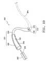
- FIG. 10is a schematic diagram of an optical signal transmission system 350 according to the third embodiment of the present invention.
- the optical signal transmission system 350comprises an optical patch cord 250 , which uses a step index fiber 260 to guide most of light beams 230 from the light source 302 uniformly into the annular region 218 of the first segment 210 (only core 212 is shown for the purpose of clarity).
- the light beam 230 entering the core 262 of the second segment 260will be guided uniformly into the region outside of the blocking region 216 of the first segment 210 due to the total reflection at the interface between the cladding 264 and the core 262 , i.e. into the annular region 218 .
- the optical patch cordcan be connected to the light source directly without using a precise coupling apparatus, the assembly and design of the optical patch cord and other optical device is therefore relatively simpler according to the present invention.
- no precise coupling apparatusis required to connect the optical patch cord and the light source, so that the present invention can dramatically decrease the total cost of the optical signal transmission system.
Landscapes
- Physics & Mathematics (AREA)
- General Physics & Mathematics (AREA)
- Optics & Photonics (AREA)
- Optical Couplings Of Light Guides (AREA)
Abstract
Description
(A) Field of the Invention
The present invention relates to a core of an optical patch cord, a method for preparing the same and an optical signal transmission system using the same, and more particularly to a core of an optical patch cord capable of connecting a light source and a multi-mode fiber with optical lossless and without using a precise coupling apparatus, and a method for preparing the same and an optical signal transmission system using the same.
(B) Description of the Related Art
An optical fiber primarily consists of a core and a cladding enclosing the core. The refraction index of the core is higher than that of the cladding, which allows a total reflection to occur when the light beam propagates from dense medium with a high refraction index to loose medium with a relative lower refraction index. Consequently, the light beam can propagate in the dense medium continuously. The optical fiber can be divided into two types: step index fibers and graded index fibers in terms of the refraction index, or single-mode fibers and multimode fibers in terms of the propagation mode.
Due to the great variation of the refraction index at the interface of the core and the cladding of the step index fiber, the light beam from the core to the cladding will be totally reflected at the interface, and the light beam will propagate continuously in the core through the total reflection. The step index fiber has many propagation modes, and each of them delivers optical signals at different speeds, which will result in signal distortions (i.e. diffusion phenomenon) because of different arriving time to the same destination site. The diameter of the core of a single-mode fiber is extremely thin, which just allows the light beam parallel to the central axis to couple into the core; therefore, the arriving time for the light beam to reach the destination point is the same. However, when the emitting spot of the light source is greater than that of the cross-sectional surface of the core of the single-mode fiber, there will be some optical loss because most of the light beam cannot couple into the core.
The refraction index of the core of the graded index fiber is designed to be a parabolic distribution and decrease with the increase of the radius. The propagation speed of the light beam in a medium decreases as the refraction index of the medium increases. A light beam deviating from the central axis propagates in the medium with a lower refraction index, so it propagates at a higher speed but a longer path; while a light beam at the central axis will propagate in a medium with a higher refraction index, so it propagates at a lower speed but a shorter path. Therefore, the time delay between the arriving times of different propagation modes, i.e., differential mode delay (DMD), depends on the refraction index distribution of the core.
When a laser beam from a single-mode laser source emits into a core such as thecore 10 of a multimode fiber, the abnormal refractingregion 12 at the center will result in pulse splitting of light signals. Therefore, when connecting a single-mode laser source with thecore 10, it is necessary to avoid the launch of the laser beam of the single-mode laser source into the center of thecore 10. U.S. Pat. No. 6,356,680 B1 teaches to set an opaque spot at the center of thecore 10 to block the laser beam from coupling into the center of thecore 10 so as to prevent the laser beam from propagating along the center of thecore 10 to reach the light sensor at the destination. Consequently, the laser beam of the single-mode laser source launching into thecore 10 at one end can only reach the light sensor at another end by propagating along the region outside theabnormal refracting region 12, and the pulse splitting resulting from the laser beam propagating along the abnormal refractingregion 12 will not occur. In addition, U.S. Pat. No. 6,356,680 B1 also teaches that the opaque spot can preferably block 90% of the energy. However, since the opaque spot at the center blocks the laser beam to launch into thecore 10, laser beam irradiating on the opaque spot will cause a 90% optical loss.
Another prior art invention for eliminating pulse splitting uses a precise coupling apparatus to connect a single-mode laser source and a multimode fiber. The laser source can only launch its laser beam into a portion of propagation modes of the multimode fiber, and the precise coupling apparatus is used in practice to launch the laser beam into the multimode fiber uniformly along the radial direction, which allows the laser beam to enter all propagation modes of the multimode fiber uniformly to avoid pulse splitting (see: Cisco systems, “Catalyst 5000 Series Mode-Conditioning Patch Cord Installation Note”). As the precise coupling apparatus must be used to assist the alignment of the laser source and the multimode fiber, it is inconvenient in assembly and design. In addition, using the precise coupling apparatus increases the total cost, which does not comply with the industrial demand.
The objective of the present invention is to provide a core of an optical patch cord capable of connecting a light source and a multi-mode fiber with optical lossless and without using a precise coupling apparatus, and a method for preparing the same and an optical signal transmission system using the same.
In order to achieve the above-mentioned objective, and avoid the problems of the prior art, the present invention discloses a core of an optical patch cord comprising a first end with a refraction index varying in a continuous manner along the radial direction, a second end including a blocking region at a radial center thereof, and a graded region extending from the first end to a predetermined position between the first end and the second end. The graded region has a refraction index distribution varying from the refraction index distribution of the first end to the refraction index distribution of the second end.
The present optical patch cord comprises a first segment including a blocking region positioned at a radial center thereof, and a second segment connected to the first segment for guiding a light beam into a region outside the blocking region of the first segment. The second segment comprises a scattering region positioned at the center of the second segment and a plurality of scattering sites positioned in the scattering region, wherein the scattering sites can be silicon crystals or micro-bubble. In addition, the second segment can also be a step index fiber with a length between 2 and 10 mm.
The present optical signal transmission system comprises a light source, a multimode fiber, and an optical patch cord including a core with a first end connected to the light source and a second end connected to the multimode fiber. The refraction index of the first end varies in a continuous manner along the radial direction and the second end has a blocking region at a radial center.
The present optical signal transmission system may comprise a multimode fiber and an optical patch cord including a first segment including a blocking region positioned at a radial center thereof and a second segment connected to the first segment for guiding a light beam into a region outside the blocking region of the first segment.
The present method for preparing an optical patch cord first prepares a core with a blocking region positioned at a radial center thereof. A thermal treatment is then performed at one end of the core to form a refraction index varying in a continuous manner along the radial direction of the core.
Compared to the prior art, the optical patch cord can be connected to the light source directly without using a precise coupling apparatus, and the assembly and design of the optical patch cord and other optical device is therefore relatively simpler according to the present invention. In addition, no precise coupling apparatus is required to connect the optical patch cord and the light source, so that the present invention can dramatically decrease the total cost of the optical signal transmission system.
Other objectives and advantages of the present invention will become apparent upon reading the following descriptions and upon reference to the accompanying drawings in which:
Referring toFIG. 4 , a thermal treatment is performed at afirst end 80 of the core70 to transform the refraction index distribution into a continuous variation. The thermal treatment is performed using a flame traveling around apredetermined range 82 to drive germanium in the core70 to diffuse into the blockingregion 92. The thermal treatment results in a continuous variation of the refraction index distribution at thefirst end 80, while the refraction index distribution of thepredetermined range 82 will vary gradually from the distribution of thefirst end 80 to that of thesecond end 90 to complete the preparation for the core30 (as shown inFIG. 5 ). Preferably, the refraction index distribution of the core30 at thefirst end 40 decreases gradually from the center to the outer edge and is maximal at the center. The exterior of the core30 will be coated with a cladding to complete the optical patch cord.
Thecore 30 of the optical patch cord has the gradedregion 60 with a graded refraction index distribution, and all light beams from thelight source 102 enter the gradedregion 60 at thefirst end 40. The light beams may undergo several refractions in the gradedregion 60 and propagate only in the annular region outside the blockingregion 52 after leaving the gradedregion 60. Consequently, when connecting the optical patch cord to thelight source 102, it just needs to guide the light beam from thelight source 102 to any region of thefirst end 40 of the core30, and the gradedregion 60 will couple and guide all the light beams to the annular region outside the blockingregion 52 automatically substantially without any optical loss. Since there is no opaque spot at thefirst end 40 where theoptical patch cord 60 is connected to thelight source 102, all the light beams from thelight source 102 are fully coupled into thecore 30 of the optical patch cord. As a result, connecting theoptical patch cord 30 and thelight source 102 will be optically lossless according to present invention.
The blockingregion 216 of thefirst segment 210 is positioned at the center, while scatteringsites 226 of thesecond segment 220 can guide thelight beam 230 from thelight source 302 uniformly into the region outside the blockingregion 216 of thefirst segment 210, i.e. into theannular region 218. Consequently, it just needs to guide thelight beam 230 from thelight source 302 into any area of thesecond segment 220 according to the present invention, and thescattering sites 226 will guide most of thelight beam 230 uniformly into theannular region 218 outside the blockingregion 216 of thefirst segment 210 automatically. As a result, thelight beam 230 will propagate in theannular region 218 rather than entering the abnormal refracting region at the center of themultimode fiber 304 when leaving thefirst segment 210, so that the pulse splitting of optical signal will not occur.
The above-described embodiments of the present invention are intended to be illustrative only. Numerous alternative embodiments may be devised by those skilled in the art without departing from the scope of the following claims.
Claims (8)
1. A core of an optical patch cord, comprising:
a first end with a refraction index varying in a continuous manner along the radial direction:
a second end including a blocking region at a radial center thereof; and
a graded region extending from the first end to a predetermined position between the first end and the second end, wherein the graded region has a refraction index distribution varying from the refraction index distribution of the first end to the refraction index distribution of the second end.
2. The core of an optical patch cord according toclaim 1 , wherein the refraction index of the first end decreases along the radial direction.
3. The core of an optical patch cord according toclaim 1 , wherein the refraction index of the first end is maximal at a radial center.
4. The core of an optical patch cord according toclaim 1 , wherein the refraction index of the second end decreases from an outer edge of the blocking region.
5. An optical signal transmission system, comprising:
a light source;
a multimode fiber; and
an optical patch cord including a core with a first end connected to the light source and a second end connected the multimode fiber, wherein a refraction index of the first end varies in a continuous manner along the radial direction and the second end has a blocking region at a radial center.
6. The optical signal transmission system according toclaim 5 , wherein the refraction index of the first end decreases along the radial direction.
7. The optical signal transmission system according toclaim 5 , wherein the refraction index of the first end is maximal at a radial center.
8. The optical signal transmission system according toclaim 5 , wherein the core further comprises a graded region extending from the first end to a predetermined positioned between the first end and the second end, and the graded region has a refraction index distribution varying from the refraction index distribution of the first end to the refraction index distribution of the second end.
Applications Claiming Priority (4)
| Application Number | Priority Date | Filing Date | Title |
|---|---|---|---|
| TW092134049ATW200519443A (en) | 2003-12-03 | 2003-12-03 | Core of optical patch cord and optical signal transmission system using the same and method for preparing the same |
| TW092134049 | 2003-12-03 | ||
| TW093114904 | 2004-05-26 | ||
| TW093126738ATW200609550A (en) | 2004-09-02 | 2004-09-02 | Optical patch cord and optical signal transmission system using the same |
Publications (2)
| Publication Number | Publication Date |
|---|---|
| US20050147369A1 US20050147369A1 (en) | 2005-07-07 |
| US7062139B2true US7062139B2 (en) | 2006-06-13 |
Family
ID=34713087
Family Applications (1)
| Application Number | Title | Priority Date | Filing Date |
|---|---|---|---|
| US10/998,607Expired - LifetimeUS7062139B2 (en) | 2003-12-03 | 2004-11-30 | Core of an optical patch cord and an optical signal transmission system using the same and a method for preparing the same |
Country Status (1)
| Country | Link |
|---|---|
| US (1) | US7062139B2 (en) |
Cited By (12)
| Publication number | Priority date | Publication date | Assignee | Title |
|---|---|---|---|---|
| US20060251367A1 (en)* | 2005-01-21 | 2006-11-09 | Martin Seifert | Fiber optic coupler, optical fiber useful with the coupler and/or a pump light source, and methods of coupling light |
| US20070285239A1 (en)* | 2006-06-12 | 2007-12-13 | Easton Martyn N | Centralized optical-fiber-based RFID systems and methods |
| US20080218355A1 (en)* | 2007-03-09 | 2008-09-11 | Downie John D | Optically addressed RFID elements |
| US20090196563A1 (en)* | 2008-02-01 | 2009-08-06 | Mullsteff David M | Multi-Fiber Optical Patch Cord Breakout Assembly |
| US7760094B1 (en) | 2006-12-14 | 2010-07-20 | Corning Cable Systems Llc | RFID systems and methods for optical fiber network deployment and maintenance |
| US7772975B2 (en) | 2006-10-31 | 2010-08-10 | Corning Cable Systems, Llc | System for mapping connections using RFID function |
| US7782202B2 (en) | 2006-10-31 | 2010-08-24 | Corning Cable Systems, Llc | Radio frequency identification of component connections |
| US8248208B2 (en) | 2008-07-15 | 2012-08-21 | Corning Cable Systems, Llc. | RFID-based active labeling system for telecommunication systems |
| US8264355B2 (en) | 2006-12-14 | 2012-09-11 | Corning Cable Systems Llc | RFID systems and methods for optical fiber network deployment and maintenance |
| US8731405B2 (en) | 2008-08-28 | 2014-05-20 | Corning Cable Systems Llc | RFID-based systems and methods for collecting telecommunications network information |
| US20150277037A1 (en)* | 2014-03-31 | 2015-10-01 | Fujitsu Limited | Optical waveguide, photoelectric hybrid board and method of manufacturing optical waveguide |
| US9563832B2 (en) | 2012-10-08 | 2017-02-07 | Corning Incorporated | Excess radio-frequency (RF) power storage and power sharing RF identification (RFID) tags, and related connection systems and methods |
Families Citing this family (4)
| Publication number | Priority date | Publication date | Assignee | Title |
|---|---|---|---|---|
| EP1811616B1 (en)* | 2005-12-16 | 2017-01-04 | OFS Fitel, LLC | Rare-earth-doped, large-mode-area, multimode, hybrid optical fibers and devices using the same |
| US8717669B2 (en) | 2008-10-17 | 2014-05-06 | The Arizona Board Of Regents | Apparatus and method of generating nearly non-diffracting beams from multimode optical fibers |
| DE102011109845B4 (en)* | 2010-11-04 | 2020-10-29 | J-Plasma Gmbh | Arrangement for the transmission of electromagnetic radiation, preferably for the application of light energy to biological structures and method for producing an optical waveguide for an arrangement |
| CN115991568B (en)* | 2023-02-21 | 2025-02-25 | 锐光信通科技有限公司 | Absorption gradient ytterbium-doped optical fiber, preform and preparation method thereof |
Citations (5)
| Publication number | Priority date | Publication date | Assignee | Title |
|---|---|---|---|---|
| US4723828A (en)* | 1984-11-09 | 1988-02-09 | Northern Telecom Limited | Bandwidth enhancement of multimode optical transmisson lines |
| US6154589A (en)* | 1998-05-21 | 2000-11-28 | Cabletron Systems, Inc. | Method and system for removal of low order optical transmission modes in multimode optical fiber computer network to improve modal bandwidth |
| US6556329B1 (en)* | 1998-05-21 | 2003-04-29 | Enterasys Networks, Inc. | Method and system for preventing low order optical transmission modes in multimode optical fiber computer network using annulus laser |
| US20030185530A1 (en)* | 2002-03-26 | 2003-10-02 | Whitney White | Multimode optical fiber having reduced intermodal dispersion |
| US6718800B2 (en)* | 1999-03-08 | 2004-04-13 | Fitel Usa Corp. | Method of collapsing a tube for an optical fiber preform |
- 2004
- 2004-11-30USUS10/998,607patent/US7062139B2/ennot_activeExpired - Lifetime
Patent Citations (6)
| Publication number | Priority date | Publication date | Assignee | Title |
|---|---|---|---|---|
| US4723828A (en)* | 1984-11-09 | 1988-02-09 | Northern Telecom Limited | Bandwidth enhancement of multimode optical transmisson lines |
| US6154589A (en)* | 1998-05-21 | 2000-11-28 | Cabletron Systems, Inc. | Method and system for removal of low order optical transmission modes in multimode optical fiber computer network to improve modal bandwidth |
| US6356680B1 (en) | 1998-05-21 | 2002-03-12 | Enterasys Networks, Inc. | Method and system for removal of low order optical transmission modes to improve modal bandwidth in a multimode optical fiber computer network |
| US6556329B1 (en)* | 1998-05-21 | 2003-04-29 | Enterasys Networks, Inc. | Method and system for preventing low order optical transmission modes in multimode optical fiber computer network using annulus laser |
| US6718800B2 (en)* | 1999-03-08 | 2004-04-13 | Fitel Usa Corp. | Method of collapsing a tube for an optical fiber preform |
| US20030185530A1 (en)* | 2002-03-26 | 2003-10-02 | Whitney White | Multimode optical fiber having reduced intermodal dispersion |
Non-Patent Citations (2)
| Title |
|---|
| "Catalyst 5000 Series Mode-Conditioning Patch Cord Installation Note", Cisco Systems., Text Part No. 1, Jan. 4, 2001. |
| J.B. Schlager et al., "Annealed Optical Fibre Mode Scrambler" Electronics Letters, vol. 37, No. 1, Jan. 4, 2001. |
Cited By (15)
| Publication number | Priority date | Publication date | Assignee | Title |
|---|---|---|---|---|
| US7412135B2 (en)* | 2005-01-21 | 2008-08-12 | Nufern | Fiber optic coupler, optical fiber useful with the coupler and/or a pump light source, and methods of coupling light |
| US20060251367A1 (en)* | 2005-01-21 | 2006-11-09 | Martin Seifert | Fiber optic coupler, optical fiber useful with the coupler and/or a pump light source, and methods of coupling light |
| US20070285239A1 (en)* | 2006-06-12 | 2007-12-13 | Easton Martyn N | Centralized optical-fiber-based RFID systems and methods |
| US7772975B2 (en) | 2006-10-31 | 2010-08-10 | Corning Cable Systems, Llc | System for mapping connections using RFID function |
| US7782202B2 (en) | 2006-10-31 | 2010-08-24 | Corning Cable Systems, Llc | Radio frequency identification of component connections |
| US8264355B2 (en) | 2006-12-14 | 2012-09-11 | Corning Cable Systems Llc | RFID systems and methods for optical fiber network deployment and maintenance |
| US7760094B1 (en) | 2006-12-14 | 2010-07-20 | Corning Cable Systems Llc | RFID systems and methods for optical fiber network deployment and maintenance |
| US20080218355A1 (en)* | 2007-03-09 | 2008-09-11 | Downie John D | Optically addressed RFID elements |
| US7547150B2 (en) | 2007-03-09 | 2009-06-16 | Corning Cable Systems, Llc | Optically addressed RFID elements |
| US20090196563A1 (en)* | 2008-02-01 | 2009-08-06 | Mullsteff David M | Multi-Fiber Optical Patch Cord Breakout Assembly |
| US8248208B2 (en) | 2008-07-15 | 2012-08-21 | Corning Cable Systems, Llc. | RFID-based active labeling system for telecommunication systems |
| US8731405B2 (en) | 2008-08-28 | 2014-05-20 | Corning Cable Systems Llc | RFID-based systems and methods for collecting telecommunications network information |
| US9058529B2 (en) | 2008-08-28 | 2015-06-16 | Corning Optical Communications LLC | RFID-based systems and methods for collecting telecommunications network information |
| US9563832B2 (en) | 2012-10-08 | 2017-02-07 | Corning Incorporated | Excess radio-frequency (RF) power storage and power sharing RF identification (RFID) tags, and related connection systems and methods |
| US20150277037A1 (en)* | 2014-03-31 | 2015-10-01 | Fujitsu Limited | Optical waveguide, photoelectric hybrid board and method of manufacturing optical waveguide |
Also Published As
| Publication number | Publication date |
|---|---|
| US20050147369A1 (en) | 2005-07-07 |
Similar Documents
| Publication | Publication Date | Title |
|---|---|---|
| US7062139B2 (en) | Core of an optical patch cord and an optical signal transmission system using the same and a method for preparing the same | |
| US3832028A (en) | Coupler for optical waveguide light source | |
| CN101788696B (en) | Optical fiber | |
| US4521070A (en) | High power laser radiation conveying device utilizing variable section fiber optics | |
| US8724945B2 (en) | High power fiber laser system with integrated termination block | |
| CN102598545B (en) | For through improveing the optical fiber end structure of multimode bandwidth and related system and method | |
| US3780295A (en) | Light source coupler for optical waveguide | |
| CN1145816C (en) | Polarization wave holding optical fiber and parts thereof | |
| CN104521077B (en) | High power spatial light filter | |
| JP6921021B2 (en) | Methods for forming clad mode strippers and clad mode strippers used with optical systems | |
| US7447409B2 (en) | Sleeved optical fiber for reduced lateral loss and method for making the same | |
| US9946040B2 (en) | Optical fibers without cladding | |
| WO2001035132A1 (en) | Optical fiber, method for manufacturing same, and optical transmission system comprising the same | |
| US20030103724A1 (en) | High power optical fiber coupling | |
| US11681110B2 (en) | Apparatus for monitoring the output of an optical system | |
| GB2169096A (en) | Joining optical fibres using numerical aperture transformer | |
| US6374009B1 (en) | TEMC fiber based optical switch | |
| GB1569132A (en) | Optical fibre having low mode dispersion | |
| JP3680565B2 (en) | Mode conditioner | |
| JP4158307B2 (en) | Optical transmission module | |
| JPS5915905A (en) | Optical fiber which maintains plane of plarization | |
| CA2493319A1 (en) | A tapered optical fibre with a reflective coating at the tapered end | |
| CN1629661A (en) | Fiber core of optical fiber connection line, preparation method thereof, and optical signal transmission system | |
| CN222580285U (en) | Multi-ring beam coupling fiber | |
| US20240385380A1 (en) | Multicore fiber attenuator |
Legal Events
| Date | Code | Title | Description |
|---|---|---|---|
| AS | Assignment | Owner name:PRIME OPTICAL FIBER CORPORATION, TAIWAN Free format text:ASSIGNMENT OF ASSIGNORS INTEREST;ASSIGNOR:SHANG, HEN-TAI;REEL/FRAME:015876/0270 Effective date:20041112 | |
| STCF | Information on status: patent grant | Free format text:PATENTED CASE | |
| FPAY | Fee payment | Year of fee payment:4 | |
| FPAY | Fee payment | Year of fee payment:8 | |
| MAFP | Maintenance fee payment | Free format text:PAYMENT OF MAINTENANCE FEE, 12TH YR, SMALL ENTITY (ORIGINAL EVENT CODE: M2553) Year of fee payment:12 | |
| AS | Assignment | Owner name:PRIME OPTICAL FIBER CORPORATION, TAIWAN Free format text:ASSIGNMENT OF ASSIGNORS INTEREST;ASSIGNOR:SUCCESS PRIME CORPORATION;REEL/FRAME:052965/0240 Effective date:20200515 Owner name:SUCCESS PRIME CORPORATION, TAIWAN Free format text:CHANGE OF NAME;ASSIGNOR:PRIME OPTICAL FIBER CORPORATION;REEL/FRAME:053757/0029 Effective date:20120813 |