US7061594B2 - Disc drive system and methods for use with bio-discs - Google Patents
Disc drive system and methods for use with bio-discsDownload PDFInfo
- Publication number
- US7061594B2 US7061594B2US10/008,156US815601AUS7061594B2US 7061594 B2US7061594 B2US 7061594B2US 815601 AUS815601 AUS 815601AUS 7061594 B2US7061594 B2US 7061594B2
- Authority
- US
- United States
- Prior art keywords
- disc
- signal
- trigger
- light
- detector
- Prior art date
- Legal status (The legal status is an assumption and is not a legal conclusion. Google has not performed a legal analysis and makes no representation as to the accuracy of the status listed.)
- Expired - Fee Related, expires
Links
- 238000000034methodMethods0.000titleclaimsdescription40
- 230000003287optical effectEffects0.000claimsabstractdescription76
- 238000012545processingMethods0.000claimsdescription41
- 230000008569processEffects0.000claimsdescription5
- 230000004048modificationEffects0.000abstractdescription10
- 238000012986modificationMethods0.000abstractdescription9
- 239000000126substanceSubstances0.000abstractdescription5
- 238000001514detection methodMethods0.000description18
- 230000006870functionEffects0.000description18
- 230000008859changeEffects0.000description13
- 238000010586diagramMethods0.000description13
- 238000003556assayMethods0.000description11
- 238000012360testing methodMethods0.000description11
- 238000013461designMethods0.000description9
- 239000000463materialSubstances0.000description9
- 238000004458analytical methodMethods0.000description6
- 239000000758substrateSubstances0.000description6
- 239000000872bufferSubstances0.000description5
- 239000012530fluidSubstances0.000description4
- 239000007788liquidSubstances0.000description4
- 238000007792additionMethods0.000description3
- 238000006243chemical reactionMethods0.000description3
- 230000001427coherent effectEffects0.000description3
- 238000012937correctionMethods0.000description3
- 230000000694effectsEffects0.000description3
- 238000010438heat treatmentMethods0.000description3
- 230000010287polarizationEffects0.000description3
- 239000004417polycarbonateSubstances0.000description3
- 230000003321amplificationEffects0.000description2
- 201000009310astigmatismDiseases0.000description2
- 239000012620biological materialSubstances0.000description2
- 210000000601blood cellAnatomy0.000description2
- 210000004027cellAnatomy0.000description2
- 238000000576coating methodMethods0.000description2
- 239000013065commercial productSubstances0.000description2
- 230000009977dual effectEffects0.000description2
- 238000005516engineering processMethods0.000description2
- PCHJSUWPFVWCPO-UHFFFAOYSA-NgoldChemical compound[Au]PCHJSUWPFVWCPO-UHFFFAOYSA-N0.000description2
- 238000005259measurementMethods0.000description2
- 230000007246mechanismEffects0.000description2
- 239000000203mixtureSubstances0.000description2
- 238000003199nucleic acid amplification methodMethods0.000description2
- 239000011368organic materialSubstances0.000description2
- 230000000737periodic effectEffects0.000description2
- 229920000515polycarbonatePolymers0.000description2
- 238000002310reflectometryMethods0.000description2
- 238000009420retrofittingMethods0.000description2
- 238000005070samplingMethods0.000description2
- 239000000725suspensionSubstances0.000description2
- YBJHBAHKTGYVGT-ZKWXMUAHSA-N(+)-BiotinChemical compoundN1C(=O)N[C@@H]2[C@H](CCCCC(=O)O)SC[C@@H]21YBJHBAHKTGYVGT-ZKWXMUAHSA-N0.000description1
- 235000000638D-biotinNutrition0.000description1
- 239000011665D-biotinSubstances0.000description1
- WQZGKKKJIJFFOK-GASJEMHNSA-NGlucoseNatural productsOC[C@H]1OC(O)[C@H](O)[C@@H](O)[C@@H]1OWQZGKKKJIJFFOK-GASJEMHNSA-N0.000description1
- 208000005228Pericardial EffusionDiseases0.000description1
- 239000004793PolystyreneSubstances0.000description1
- 108010090804StreptavidinProteins0.000description1
- 230000001133accelerationEffects0.000description1
- 238000013019agitationMethods0.000description1
- XAGFODPZIPBFFR-UHFFFAOYSA-NaluminiumChemical compound[Al]XAGFODPZIPBFFR-UHFFFAOYSA-N0.000description1
- 229910052782aluminiumInorganic materials0.000description1
- 210000004381amniotic fluidAnatomy0.000description1
- 238000013459approachMethods0.000description1
- 238000003491arrayMethods0.000description1
- 230000005540biological transmissionEffects0.000description1
- 210000004369bloodAnatomy0.000description1
- 239000008280bloodSubstances0.000description1
- 239000006227byproductSubstances0.000description1
- 210000001175cerebrospinal fluidAnatomy0.000description1
- 239000003153chemical reaction reagentSubstances0.000description1
- 239000003795chemical substances by applicationSubstances0.000description1
- 238000004737colorimetric analysisMethods0.000description1
- 238000007398colorimetric assayMethods0.000description1
- 238000004891communicationMethods0.000description1
- 230000001143conditioned effectEffects0.000description1
- 230000008878couplingEffects0.000description1
- 238000010168coupling processMethods0.000description1
- 238000005859coupling reactionMethods0.000description1
- 238000013500data storageMethods0.000description1
- 230000007547defectEffects0.000description1
- 238000011161developmentMethods0.000description1
- 210000003608feceAnatomy0.000description1
- 239000008103glucoseSubstances0.000description1
- 229910052737goldInorganic materials0.000description1
- 239000010931goldSubstances0.000description1
- 238000003384imaging methodMethods0.000description1
- 230000002452interceptive effectEffects0.000description1
- 238000011835investigationMethods0.000description1
- 239000004816latexSubstances0.000description1
- 229920000126latexPolymers0.000description1
- 210000000265leukocyteAnatomy0.000description1
- 239000011325microbeadSubstances0.000description1
- 239000004005microsphereSubstances0.000description1
- 238000002156mixingMethods0.000description1
- 238000012544monitoring processMethods0.000description1
- 108010087904neutravidinProteins0.000description1
- 238000010606normalizationMethods0.000description1
- 210000000056organAnatomy0.000description1
- 239000002245particleSubstances0.000description1
- 210000004912pericardial fluidAnatomy0.000description1
- 239000004033plasticSubstances0.000description1
- 210000004910pleural fluidAnatomy0.000description1
- 229920002223polystyrenePolymers0.000description1
- 238000012805post-processingMethods0.000description1
- 239000000047productSubstances0.000description1
- 230000001681protective effectEffects0.000description1
- 230000004044responseEffects0.000description1
- 210000003296salivaAnatomy0.000description1
- 210000000582semenAnatomy0.000description1
- 238000000926separation methodMethods0.000description1
- 210000002966serumAnatomy0.000description1
- 210000004927skin cellAnatomy0.000description1
- 238000009987spinningMethods0.000description1
- 210000001179synovial fluidAnatomy0.000description1
- 210000001519tissueAnatomy0.000description1
- 238000012546transferMethods0.000description1
- 210000002700urineAnatomy0.000description1
- XLYOFNOQVPJJNP-UHFFFAOYSA-NwaterSubstancesOXLYOFNOQVPJJNP-UHFFFAOYSA-N0.000description1
Images


Classifications
- G—PHYSICS
- G11—INFORMATION STORAGE
- G11B—INFORMATION STORAGE BASED ON RELATIVE MOVEMENT BETWEEN RECORD CARRIER AND TRANSDUCER
- G11B19/00—Driving, starting, stopping record carriers not specifically of filamentary or web form, or of supports therefor; Control thereof; Control of operating function ; Driving both disc and head
- G—PHYSICS
- G01—MEASURING; TESTING
- G01N—INVESTIGATING OR ANALYSING MATERIALS BY DETERMINING THEIR CHEMICAL OR PHYSICAL PROPERTIES
- G01N35/00—Automatic analysis not limited to methods or materials provided for in any single one of groups G01N1/00 - G01N33/00; Handling materials therefor
- G01N35/00029—Automatic analysis not limited to methods or materials provided for in any single one of groups G01N1/00 - G01N33/00; Handling materials therefor provided with flat sample substrates, e.g. slides
- G01N35/00069—Automatic analysis not limited to methods or materials provided for in any single one of groups G01N1/00 - G01N33/00; Handling materials therefor provided with flat sample substrates, e.g. slides whereby the sample substrate is of the bio-disk type, i.e. having the format of an optical disk
- G—PHYSICS
- G11—INFORMATION STORAGE
- G11B—INFORMATION STORAGE BASED ON RELATIVE MOVEMENT BETWEEN RECORD CARRIER AND TRANSDUCER
- G11B19/00—Driving, starting, stopping record carriers not specifically of filamentary or web form, or of supports therefor; Control thereof; Control of operating function ; Driving both disc and head
- G11B19/02—Control of operating function, e.g. switching from recording to reproducing
- B—PERFORMING OPERATIONS; TRANSPORTING
- B01—PHYSICAL OR CHEMICAL PROCESSES OR APPARATUS IN GENERAL
- B01J—CHEMICAL OR PHYSICAL PROCESSES, e.g. CATALYSIS OR COLLOID CHEMISTRY; THEIR RELEVANT APPARATUS
- B01J2219/00—Chemical, physical or physico-chemical processes in general; Their relevant apparatus
- B01J2219/00274—Sequential or parallel reactions; Apparatus and devices for combinatorial chemistry or for making arrays; Chemical library technology
- B01J2219/00277—Apparatus
- B01J2219/00497—Features relating to the solid phase supports
- B01J2219/005—Beads
- B—PERFORMING OPERATIONS; TRANSPORTING
- B01—PHYSICAL OR CHEMICAL PROCESSES OR APPARATUS IN GENERAL
- B01J—CHEMICAL OR PHYSICAL PROCESSES, e.g. CATALYSIS OR COLLOID CHEMISTRY; THEIR RELEVANT APPARATUS
- B01J2219/00—Chemical, physical or physico-chemical processes in general; Their relevant apparatus
- B01J2219/00274—Sequential or parallel reactions; Apparatus and devices for combinatorial chemistry or for making arrays; Chemical library technology
- B01J2219/00277—Apparatus
- B01J2219/00497—Features relating to the solid phase supports
- B01J2219/00527—Sheets
- B01J2219/00536—Sheets in the shape of disks
- B—PERFORMING OPERATIONS; TRANSPORTING
- B01—PHYSICAL OR CHEMICAL PROCESSES OR APPARATUS IN GENERAL
- B01J—CHEMICAL OR PHYSICAL PROCESSES, e.g. CATALYSIS OR COLLOID CHEMISTRY; THEIR RELEVANT APPARATUS
- B01J2219/00—Chemical, physical or physico-chemical processes in general; Their relevant apparatus
- B01J2219/00274—Sequential or parallel reactions; Apparatus and devices for combinatorial chemistry or for making arrays; Chemical library technology
- B01J2219/00277—Apparatus
- B01J2219/0054—Means for coding or tagging the apparatus or the reagents
- B—PERFORMING OPERATIONS; TRANSPORTING
- B01—PHYSICAL OR CHEMICAL PROCESSES OR APPARATUS IN GENERAL
- B01J—CHEMICAL OR PHYSICAL PROCESSES, e.g. CATALYSIS OR COLLOID CHEMISTRY; THEIR RELEVANT APPARATUS
- B01J2219/00—Chemical, physical or physico-chemical processes in general; Their relevant apparatus
- B01J2219/00274—Sequential or parallel reactions; Apparatus and devices for combinatorial chemistry or for making arrays; Chemical library technology
- B01J2219/00583—Features relative to the processes being carried out
- B01J2219/00585—Parallel processes
- B—PERFORMING OPERATIONS; TRANSPORTING
- B01—PHYSICAL OR CHEMICAL PROCESSES OR APPARATUS IN GENERAL
- B01J—CHEMICAL OR PHYSICAL PROCESSES, e.g. CATALYSIS OR COLLOID CHEMISTRY; THEIR RELEVANT APPARATUS
- B01J2219/00—Chemical, physical or physico-chemical processes in general; Their relevant apparatus
- B01J2219/00274—Sequential or parallel reactions; Apparatus and devices for combinatorial chemistry or for making arrays; Chemical library technology
- B01J2219/00583—Features relative to the processes being carried out
- B01J2219/00596—Solid-phase processes
- B—PERFORMING OPERATIONS; TRANSPORTING
- B01—PHYSICAL OR CHEMICAL PROCESSES OR APPARATUS IN GENERAL
- B01J—CHEMICAL OR PHYSICAL PROCESSES, e.g. CATALYSIS OR COLLOID CHEMISTRY; THEIR RELEVANT APPARATUS
- B01J2219/00—Chemical, physical or physico-chemical processes in general; Their relevant apparatus
- B01J2219/00274—Sequential or parallel reactions; Apparatus and devices for combinatorial chemistry or for making arrays; Chemical library technology
- B01J2219/00583—Features relative to the processes being carried out
- B01J2219/00603—Making arrays on substantially continuous surfaces
- B01J2219/00605—Making arrays on substantially continuous surfaces the compounds being directly bound or immobilised to solid supports
- B01J2219/0061—The surface being organic
- B—PERFORMING OPERATIONS; TRANSPORTING
- B01—PHYSICAL OR CHEMICAL PROCESSES OR APPARATUS IN GENERAL
- B01J—CHEMICAL OR PHYSICAL PROCESSES, e.g. CATALYSIS OR COLLOID CHEMISTRY; THEIR RELEVANT APPARATUS
- B01J2219/00—Chemical, physical or physico-chemical processes in general; Their relevant apparatus
- B01J2219/00274—Sequential or parallel reactions; Apparatus and devices for combinatorial chemistry or for making arrays; Chemical library technology
- B01J2219/00583—Features relative to the processes being carried out
- B01J2219/00603—Making arrays on substantially continuous surfaces
- B01J2219/00605—Making arrays on substantially continuous surfaces the compounds being directly bound or immobilised to solid supports
- B01J2219/00614—Delimitation of the attachment areas
- B01J2219/00621—Delimitation of the attachment areas by physical means, e.g. trenches, raised areas
- B—PERFORMING OPERATIONS; TRANSPORTING
- B01—PHYSICAL OR CHEMICAL PROCESSES OR APPARATUS IN GENERAL
- B01J—CHEMICAL OR PHYSICAL PROCESSES, e.g. CATALYSIS OR COLLOID CHEMISTRY; THEIR RELEVANT APPARATUS
- B01J2219/00—Chemical, physical or physico-chemical processes in general; Their relevant apparatus
- B01J2219/00274—Sequential or parallel reactions; Apparatus and devices for combinatorial chemistry or for making arrays; Chemical library technology
- B01J2219/00583—Features relative to the processes being carried out
- B01J2219/00603—Making arrays on substantially continuous surfaces
- B01J2219/00605—Making arrays on substantially continuous surfaces the compounds being directly bound or immobilised to solid supports
- B01J2219/00623—Immobilisation or binding
- B01J2219/0063—Other, e.g. van der Waals forces, hydrogen bonding
- B—PERFORMING OPERATIONS; TRANSPORTING
- B01—PHYSICAL OR CHEMICAL PROCESSES OR APPARATUS IN GENERAL
- B01J—CHEMICAL OR PHYSICAL PROCESSES, e.g. CATALYSIS OR COLLOID CHEMISTRY; THEIR RELEVANT APPARATUS
- B01J2219/00—Chemical, physical or physico-chemical processes in general; Their relevant apparatus
- B01J2219/00274—Sequential or parallel reactions; Apparatus and devices for combinatorial chemistry or for making arrays; Chemical library technology
- B01J2219/00583—Features relative to the processes being carried out
- B01J2219/00603—Making arrays on substantially continuous surfaces
- B01J2219/00605—Making arrays on substantially continuous surfaces the compounds being directly bound or immobilised to solid supports
- B01J2219/00632—Introduction of reactive groups to the surface
- B01J2219/00637—Introduction of reactive groups to the surface by coating it with another layer
- B—PERFORMING OPERATIONS; TRANSPORTING
- B01—PHYSICAL OR CHEMICAL PROCESSES OR APPARATUS IN GENERAL
- B01J—CHEMICAL OR PHYSICAL PROCESSES, e.g. CATALYSIS OR COLLOID CHEMISTRY; THEIR RELEVANT APPARATUS
- B01J2219/00—Chemical, physical or physico-chemical processes in general; Their relevant apparatus
- B01J2219/00274—Sequential or parallel reactions; Apparatus and devices for combinatorial chemistry or for making arrays; Chemical library technology
- B01J2219/00583—Features relative to the processes being carried out
- B01J2219/00603—Making arrays on substantially continuous surfaces
- B01J2219/00646—Making arrays on substantially continuous surfaces the compounds being bound to beads immobilised on the solid supports
- B01J2219/00648—Making arrays on substantially continuous surfaces the compounds being bound to beads immobilised on the solid supports by the use of solid beads
- B—PERFORMING OPERATIONS; TRANSPORTING
- B01—PHYSICAL OR CHEMICAL PROCESSES OR APPARATUS IN GENERAL
- B01J—CHEMICAL OR PHYSICAL PROCESSES, e.g. CATALYSIS OR COLLOID CHEMISTRY; THEIR RELEVANT APPARATUS
- B01J2219/00—Chemical, physical or physico-chemical processes in general; Their relevant apparatus
- B01J2219/00274—Sequential or parallel reactions; Apparatus and devices for combinatorial chemistry or for making arrays; Chemical library technology
- B01J2219/00583—Features relative to the processes being carried out
- B01J2219/00603—Making arrays on substantially continuous surfaces
- B01J2219/00659—Two-dimensional arrays
- B—PERFORMING OPERATIONS; TRANSPORTING
- B01—PHYSICAL OR CHEMICAL PROCESSES OR APPARATUS IN GENERAL
- B01J—CHEMICAL OR PHYSICAL PROCESSES, e.g. CATALYSIS OR COLLOID CHEMISTRY; THEIR RELEVANT APPARATUS
- B01J2219/00—Chemical, physical or physico-chemical processes in general; Their relevant apparatus
- B01J2219/00274—Sequential or parallel reactions; Apparatus and devices for combinatorial chemistry or for making arrays; Chemical library technology
- B01J2219/0068—Means for controlling the apparatus of the process
- B01J2219/00686—Automatic
- B01J2219/00689—Automatic using computers
- B—PERFORMING OPERATIONS; TRANSPORTING
- B01—PHYSICAL OR CHEMICAL PROCESSES OR APPARATUS IN GENERAL
- B01J—CHEMICAL OR PHYSICAL PROCESSES, e.g. CATALYSIS OR COLLOID CHEMISTRY; THEIR RELEVANT APPARATUS
- B01J2219/00—Chemical, physical or physico-chemical processes in general; Their relevant apparatus
- B01J2219/00274—Sequential or parallel reactions; Apparatus and devices for combinatorial chemistry or for making arrays; Chemical library technology
- B01J2219/0068—Means for controlling the apparatus of the process
- B01J2219/00702—Processes involving means for analysing and characterising the products
- B—PERFORMING OPERATIONS; TRANSPORTING
- B01—PHYSICAL OR CHEMICAL PROCESSES OR APPARATUS IN GENERAL
- B01J—CHEMICAL OR PHYSICAL PROCESSES, e.g. CATALYSIS OR COLLOID CHEMISTRY; THEIR RELEVANT APPARATUS
- B01J2219/00—Chemical, physical or physico-chemical processes in general; Their relevant apparatus
- B01J2219/00274—Sequential or parallel reactions; Apparatus and devices for combinatorial chemistry or for making arrays; Chemical library technology
- B01J2219/00718—Type of compounds synthesised
- B01J2219/0072—Organic compounds
- B01J2219/0074—Biological products
- C—CHEMISTRY; METALLURGY
- C40—COMBINATORIAL TECHNOLOGY
- C40B—COMBINATORIAL CHEMISTRY; LIBRARIES, e.g. CHEMICAL LIBRARIES
- C40B70/00—Tags or labels specially adapted for combinatorial chemistry or libraries, e.g. fluorescent tags or bar codes
- G—PHYSICS
- G11—INFORMATION STORAGE
- G11B—INFORMATION STORAGE BASED ON RELATIVE MOVEMENT BETWEEN RECORD CARRIER AND TRANSDUCER
- G11B7/00—Recording or reproducing by optical means, e.g. recording using a thermal beam of optical radiation by modifying optical properties or the physical structure, reproducing using an optical beam at lower power by sensing optical properties; Record carriers therefor
- G11B7/002—Recording, reproducing or erasing systems characterised by the shape or form of the carrier
- G11B7/0037—Recording, reproducing or erasing systems characterised by the shape or form of the carrier with discs
Definitions
- the present inventionrelates to the use of optical discs and optical disc readers for performing assays.
- Deriving information about operational structures and investigational features using a single optical pathmay require complex manipulation of the information processed in the optical path, as discussed, for example, in copending commonly-assigned U.S. patent application Ser. No. 09/378,878, which is hereby incorporated by reference in its entirety.
- the present inventionprovides methods and apparatus for detecting investigational features on an optical disc.
- the structures, features, characteristics, and attributes which can be investigated according to the present invention with investigational featuresmay include biological, chemical, or organic specimens, test samples, investigational objects such as organic material, and similar test objects or target samples. Such structures, features, and attributes may be imaged on an output monitor.
- the investigational featuresmay also include specific chemical reactions and the products and by-products resulting therefrom, such as, any one of a variety of different colorimetric assays. These features can be used for medical assays, but also for other uses, such as to detect chemicals or detect water purity.
- An optical bio-discmay be implemented on an optical disc including a format such as CD, CD-R, CD-RW, DVD, DVD-R, DVD-RW, or a modified version thereof.
- the bio-discmay include encoded information for performing, controlling, and post-processing the test or assay. For example, such encoded information may be directed to controlling the rotation rate of the disc. Depending on the test, assay, or investigational protocol, the rotation rate may be variable with intervening or consecutive sessions of acceleration, constant speed, and deceleration. These sessions may be closely controlled both as to speed and time of rotation to provide, for example, mixing, agitation, or separation of fluids and suspensions with agents, reagents or antibodies.
- a disc drive assemblyis employed to rotate the disc, read and process any encoded information stored on the disc, and analyze the liquid, chemical, biological, or biochemical component or other investigational feature in an assay zone of the disc.
- the disc drive assemblymay also be utilized to write information to the bio-disc either before or after the material in the assay zone is analyzed by the read beam of the drive.
- one or more signal processing circuits within an optical disc driveare programmably configured to function as an analog to digital converter (ADC), and preferably to bypass demodulator and error correction circuitry.
- ADCanalog to digital converter
- the ADCis used to detect an electronic profile associated with investigational features on or in the optical disc. The profiles may be used to determine relative size, composition, and location of the detected structures.
- the disc drivemay optionally be programmably returned to its standard operating configuration.
- the ADC functionalitymay be incorporated in a digital signal processor (DSP) which is programmable without hardware change.
- DSPdigital signal processor
- the programmingmay cause the signal from the ADC to be provided to an output lead of the DSP, or the programming could cause the signal to essentially pass through other components from the ADC without being substantially altered.
- the present applicationrelates to other ways in which a conventional optical disc drive having a light source, a detector for detecting light reflected from the light source to the disc, and various signal processing circuitry may be used to obtain information about an investigational feature.
- the discis made using a semi-reflective (and semi-transparent) material such that light can be reflected and detected by the disc drives normal detector. Additional functionality can be provided over the disc to detect transmitted light. These additional components can use a detector with one or more detecting elements, a pre-amplifier, automatic gain control, an analog switch for combining signals from multiple elements (if provided), and additional processing circuitry including an ADC, microprocessor, and/or threshold detector and event counter. These items are preferably provided on a board that can be added to the device through retro-fitting such that a conventional, commercial disc drive, preferably of the type that can be provided into a compartment of a personal computer is modified without changing the basic functionality of the disc drive. In the preferred embodiment, no wires need be attached to the reflective light source, detector, or processing circuitry, although some connections could be made if desired, for example, to compare signals received by the top and bottom detectors.
- the encoded informationis provided as it conventionally is in a CD, CD/R, or DVD, while investigational features are provided at target zones where the encoded information is removed, allowing more transmission with less reflection.
- the systempreferably includes a form of triggering that can either be hardware or software based.
- a triggering signalindicates that an investigational feature is being observed. This can arise from a physical trigger mark located on the disc that identifies a radius along which there are target zones with investigational features, or it can include encoded data identifying where a target zone is located.
- the signal from the triggering sensorcan be provided to an ADC or other processing circuitry that causes that circuitry to process the current detector signal; in the case of software triggering, the software controls the ADC or other processing circuitry.
- the data collected under software controlis subsequently searched through for the software trigger data pattern. This pattern identifies the location in the data of the investigational features.
- firmware changesare ones that are known in the field of disc analysis and/or drive analysis, but are not used in conventional disc drive systems and would generally be considered unnecessary or even undesirable.
- firmware changesare ones that are known in the field of disc analysis and/or drive analysis, but are not used in conventional disc drive systems and would generally be considered unnecessary or even undesirable.
- a usersuch as a consumer, would typically want to use a disc that plays music or provides data, without setting parameters. Consequently, conventional systems generally have no need or desire for monitoring or controlling such other parameters.
- firmware changes that are useful in a disc drive system for detecting investigational featuresmay be made.
- a fluidis provided into a channel to be moved along the channel in response to rotation, and detected by the laser/detector in a drive
- Another use of such firmware changescan be to monitor a parameter that indicates some useful information about an investigational feature.
- automatic gain controlcan be provided so that the detector output signal is amplified by a variable amount.
- the amount of gainis inversely related to the amount of light falling on the detector.
- the deviceis only reading binary data (0 or 1), but an investigational feature may require data to be read over a continuum of values.
- the level of gainmay serve as an indicator of the investigational feature—the larger the gain the smaller the, and vice versa.
- the automatic gain control valuecan thus be used to image, detect, or assess the investigational feature.
- firmware changeshave been mentioned here, the embodiments below indicate a number of other features that are useful modifications to a conventional drive. By making these changes in firmware. the drive capabilities can be modified in some respects and yet use conventional hardware is modified.
- an optical disc systemperforms a number of functions, including tracking, focusing, and synchronizing.
- a single signale.g., a quad-sum signal
- these functionsare said to be linked.
- the linking of individual functionscan be problematic because the optimal system settings for performing each of these functions may be different.
- the optimal pit depth for retrieving tracking informationis 1 ⁇ 8 the wavelength of the light beam used by the system.
- the optimal pit depth for retrieving synchronization informationis 1 ⁇ 4 the light beam wavelength. Because only one signal is being used for both tracking and synchronization, this difference requires that a pit depth be chosen that optimizes neither the tracking nor the synchronization functions.
- the tracking signalcan be isolated from the synchronization signal and each set of pits can be formed to meet the optimal requirements for each function.
- the pits used for trackingcan be formed with a depth of 1 ⁇ 8 the light wavelength that is used to read the signal
- the pits used for synchronizationcan be formed to be 1 ⁇ 4 the light wavelength that is used to read the signal.
- one signalcan be generated to detect the standard optical disc operational information, such as tracking, focus, and synchronization, while another signal can be generated to detect investigational features or structures disposed on the same or different surface of the disc assembly.
- the systemcan separately detect operational data and investigational features located on one or more surfaces of an optical disc assembly.
- a photodiode arrayis a set of one or more photo-detector elements.
- One method of generating multiple coherent or non-coherent light beamsis by passing the light through a diffraction grating, which can be a screen with slits spaced only a few light wavelengths apart.
- a one-beam pickupaccomplishes all of these tasks with one beam.
- one beammay also be used to provide all the tasks of a typical optical system and the additional beams may be used to detect investigational features or structures on the optical disc assembly concurrently or nonconcurrently.
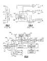
- FIG. 1is a perspective view and block diagram of a disc and disc reading system.
- FIG. 2is a side cross-sectional view of a disc.
- FIG. 3is a perspective view of a surface of a CD-R disc with wobble grooves.
- FIG. 4is an exemplary optical disc detector and associated electronics that use three beams for tracking, focusing, and reading.
- FIG. 5shows the position of beams from a typical three-beam pickup relative to a track on an optical disc.
- FIG. 6is a block diagram of a chip set of a generic optical disc reader, modified to monitor signals for determining the presence of investigational features or structures on an optical disc.
- FIG. 7illustrates a cross sectional side of a suitable disc assembly, including a light-refractive cover, for use with the present invention.
- FIG. 8is a functional block diagram of a conventional CD digital signal processing circuit.
- FIG. 9is a functional block diagram of a digital signal processing circuit programmably configured as an analog to digital converter in accordance with the principles of the present invention.
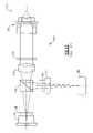
- FIG. 10is a block diagram of a known light projection and detection system.
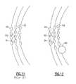
- FIG. 11is a prior art view showing a three-beam system projecting onto three tracks of the disc.
- FIG. 12is a top view of three beams on three tracks, one of which has an investigational feature.
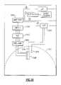
- FIG. 13is a block diagram of an overall drive system according to an embodiment of the present invention.
- FIG. 14is a part pictorial part block diagram showing a disc and a reading system.
- FIG. 15is a plan view of a disc showing assay regions and a hardware trigger.
- FIG. 16is a block diagram of a board with functionality including a trigger, an amplifier, and detection circuitry.
- FIG. 1shows an optical disc reader system 10 .
- This systemmay be a conventional reader for CD, CD-R, DVD, or other known comparable format. a modified version thereof, or a distinct dedicated device.
- the basic components of an optical reading systemare a light system for providing light. motors for rotating the disc and moving the light system, and a detection system for detecting light and processing signals.
- a light source 12provides light to optical components 20 to produce an incident light beam 14 , and a return beam 16 .
- return beam 16is reflected from a reflective surface.
- Return beam 16is provided back to optical components 20 , and then to a bottom detector 22 .
- Optical components 20can include a lens, a beam splitter, and a quarter wave plate that changes the polarization of the light beam so that the beam splitter directs a reflected beam through the lens to focus the reflected beam onto the detector.
- An astigmatic elementsuch as a cylindrical lens, may be provided between the beam splitter and detector to introduce astigmatism in the reflected light beam.
- Data from detector 22is provided to a computer 25 with a processor 24 and an analyzer 26 to provide an image to a monitor 28 .
- the computercan represent a desktop computer, programmable logic, or some other processing device, and also can include a connection (such as over the Internet) to other processing and/or storage devices.
- a drive motor 30 and a controller 32are provided for controlling the rotation of disc 40 . Methods and systems for reading such a disc are also shown in the incorporated U.S. Pat. No. 5,892,577.
- a hardware trigger sensor 42may be used. Triggering sensor 42 provides a signal to processor 24 that allows for the collection of data by processor 24 only when incident beam 14 is on a target zone. In this case, data is not collected when the trigger is not detected.
- the triggeris preferably aligned radially with target zones. Trigger sensor 42 may be located on the bottom side of the disk 40 .
- the systemmay also include a top detector 46 for detecting transmitted light 44 .
- This lightcould pass through a semi-reflective disc, or through a portion where portions of the disc have been removed.
- the disc drive assemblyis thus employed to rotate disc 40 , read and process any encoded operational information stored on the disc, analyze the liquid, chemical, biological, or biochemical investigational features in an assay region of the disc, to write information to the disc either before or after the material in the assay zone is analyzed by the read beam of the drive.
- the remaining componentsare parts of generally known optical disc readers, and the incorporated '577 patent shows the use of a separate top detector and bottom detector.
- disc 190has layers from light-proximal to light-distal, including transmissive substrate 192 (such as 1.2 mm polycarbonate), reflective layer 194 (such as a gold or aluminum layer), and a protective cap layer 196 .
- Transparent substrate 192makes up most of the thickness of a typical CD-type disc, as measured along the optical axis, and provides both optical and structural features necessary for disc operation.
- Substrate layer 192is typically impressed with a spiral track that starts at the innermost readable portion of the disc and then spirals out to the outermost readable portion of the disc.
- this trackis made up of a series of embossed pits, each typically having a depth of approximately one-quarter the wavelength of the light that is used to read the disc.
- the pitshave varying lengths. The length and spacing of the pits encode operational data.
- the spiral groove of a recordable disc, such as CD-Rhas a wobble groove rather than pits.
- FIG. 3shows two portions of such a wobble groove, i.e., an embossed portion 200 and a groove portion 198 .
- Detector 180typically includes a central detector 182 , and can be bordered by additional detector elements 184 and 186 .
- Central detector 182may be split into multiple detector elements, e.g., four, represented as a, b, c, and d.
- Detector elements a, b, c, and d(sometimes collectively referred to as a “quad detector”) each provide electrical signal indicative of the intensity of the reflected light beam striking that element.
- the sum of the signals from center detector 182(i.e., a+b+c+d) provides a radio frequency (RF) signal 240 , also referred to as a high frequency (HF), quad-sum, or sum signal.
- RFradio frequency
- HFhigh frequency
- quad-sumquad-sum
- a tracking (tracking error, or TE) signal 242may be obtained from the difference between the e and f signals (i.e., e ⁇ f).
- a focus error (FE) signal 244may be obtained from the difference between the (a+c) and (b+d) signals.
- the circuitry of FIG. 4is just one example of circuitry that provides focus and tracking error signals in an optical disc player. Numerous methods are known for providing these signals. For example, a focus error signal may be obtained by the critical angle method, described in U.S. Pat. No. 5,629,514, or by Foucault and astigmatism methods, described in The Compact Disc Handbook by Pohlmann, A-R Editions, Inc. (1992), which are incorporated herein by reference. Similarly, tracking error signals may be obtained using a single beam push-pull or a three beam method described in The Compact Disc Handbook , a differential phase method described in U.S. Pat. No. 5,130,963, which is incorporated herein by reference, or a single beam high frequency wobble method.
- a CD drivetypically uses a three-beam pickup, in which the light beam is split into three beams, a main beam and two tracking beams.
- the main beamis focused onto the surface of an optical disc so that it is centered on a tracking structure, whereas the tracking beams fall on the opposite sides of the tracking structure.
- Main beam 210is shown centered on track 214 (as defined by pits 212 ), and tracking beams 213 falling on opposite sides of track 214 .
- the three beamsare reflected from the optical disc and directed to detector 180 ( FIG. 4 ) such that main beam 210 falls on the quad detector, and tracking beams 213 fall on sensor elements e and f.
- processingis performed by analog circuitry in combination with one or more integrated circuit chips.
- the circuitrytakes the form of a special chip set or a single ASIC (application-specific integrated circuit) chip.
- FIG. 6is generalized block diagram including an illustrative chip set 300 for a typical optical drive system. Although the chip sets for CD, CD-R, and DVD drives can be somewhat different from one another, it will be understood that the system shown in FIG. 6 is meant to generically represent all types of optical drives.
- RF signal 240obtained from summing the signals from detector elements a, b, c, and d, is normally processed to extract whatever data is recorded on the optical disc.
- analog RF signal 240is conditioned, with normalization and equalization performed.
- RF analog signal 240is converted to a digital signal comprising a serial stream of digital data referred to as channel bits.
- the channel bit streamis then demodulated according to the modulation standard used for the type of optical disc being read. For example, it is common for CD-type discs to use eight-to-fourteen (also denominated “eight-of-fourteen”) modulation (EFM) wherein a data byte, or eight data bits, are encoded in fourteen channel bits.
- EFMeight-to-fourteen
- RF signal 240 from detector 180may be converted to a square wave signal 312 by a comparator 310 , which provides a high output when RF signal 240 is above a threshold level, and a low output when RF signal is below the threshold.
- Digital signal processing circuit (DSP) 320then samples square wave signal 312 to determine the value of each channel bit. DSP 320 further demodulates the channel bits to extract the data bytes which are then grouped into blocks and processed to detect and correct errors that may have occurred.
- Memory 330provides temporary storage for the data as it is being processed by DSP 320 and assembled into blocks.
- Servo block 340analyzes tracking error (TE) signal 242 (or a wobble tracking error (WTE) in a DVD or CD-R system) and provides a tracking control signal 342 to the tracking mechanisms to ensure the pickup assembly maintains proper tracking. Similarly, a focus control signal 344 is provided based on focus error signal FE 244 . DSP 320 provides an indication of the data rate of RF signal 240 which is used by servo block 340 to provide a speed control signal 346 to the spindle motor (not shown) of the optical disc drive.
- TEtracking error
- WTEwobble tracking error
- each data blockis sent to audio reproduction circuitry (not shown).
- each data blockmay contain additional error detection codes (EDC) and error correction codes (ECC).
- EDC/ECC circuitry 350typically uses the EDC and ECC codes to increase the integrity of the data block by detecting and correcting errors not already corrected by DSP 320 .
- Memory 332which may be combined with memory 330 , provides temporary storage for data blocks being processed by EDC/ECC circuitry 350 .
- the data blocksare transferred from the optical disc player to a host 370 by means of interface circuitry 360 .
- An ATAPI interfaceis shown, but it should be understood that other interfaces, such as SCSI, Firewire, or Universal Serial Bus (USB), and the like could also be used.
- Controller 380coordinates the operation of the various components of chip set 300 , for example by coordinating the transfer of data blocks between DSP 320 and EDC/ECC circuitry 350 . Controller 380 also keeps track of which data block is being read and may keep track of various parameters indicative of the operational status of the optical disc reader.
- Program memory 390has program code for the operation of controller 380 .
- program memory 390may also contain program instructions for DSP 320 or EDC/ECC circuitry 350 . This is advantageous for manufacturers in that the operation of the disc drive may be changed by altering the program code in program memory 390 . For example, a newly developed method of modulating or encoding data on an optical disc may be accommodated by changing program memory 390 .
- Chip set 300can be modified from its original configuration by the addition of tap buffers 260 , 270 , and 280 . These tap buffers provide access to unprocessed analog signals such as RF signal 240 , TE signal 242 , and FE signal 244 , respectively, produced by detector 180 , thereby permitting external instrumentation to receive these signals without interfering with normal drive operation.
- tap buffers 260 , 270 , and 280These tap buffers provide access to unprocessed analog signals such as RF signal 240 , TE signal 242 , and FE signal 244 , respectively, produced by detector 180 , thereby permitting external instrumentation to receive these signals without interfering with normal drive operation.
- An alternative modificationis the addition of tap buffers to allow the unprocessed a though f signal from detector 180 to be processed by external instrumentation or additional circuitry. From these signals, the HF, TE, FE, or any other combination can be formed. Also, any additional detectors available can provide useful signals in this same manner (e.g., g and h detectors in current state-of-the-art drives). certain drive circuit designs and detector/amplifier devices allow connection of the instrumentation or additional circuitry directly to the detector without the need for the tap buffers.
- micron-sized investigational featuresmay be disposed upon a surface of an optical disc in a number of ways.
- One suitable embodiment for accomplishing thisis depicted in FIG. 7 .
- light beam 50is incident on the disc assembly from below.
- Disc 52has disc substrate 54 and reflective layer 56 , upon which investigational features 136 are disposed.
- Wobble groove 58impressed in substrate 54 and coated by reflective layer 56 , is indicated.
- a nonintegral cover 60is also shown.
- Investigational features 62may be detected, measured, and characterized if reflective layer 56 is not fully reflective.
- the operational structures of the disc, including tracking features,may be detected concurrently (or nonconcurrently) with and readily discriminated from investigational features using a single optical pickup.
- Investigational feature 63is shown in a target zone in which the reflective layer is removed, thereby allowing light to be transmitted more easily without a reflective or semi-reflective layer.
- the disccan have a number of target zones 65 , and these are preferably aligned along radii of the disc.
- the material applied to the disc for investigation and analysismay include biological particulate suspensions and organic material such as blood, urine, saliva, amniotic fluid, skin cells, cerebrospinal fluid, serum. synovial fluid, semen, single-strand and double-strand DNA. pleural fluid, cells from selected body organs or tissue, pericardial fluid, feces, perintoneal fluid, and calculi.
- a reportermay be employed for detection purposes. These reporters include plastic micro-spheres or beads made of, for example, latex or polystyrene and colloidal gold particles with coatings of bio-molecules that have an affinity for a given material such as a biotine molecule in a strand of DNA. Appropriate coatings include those made from streptavidin or neutravidin, for example. In this manner, objects to small to be detected by the read beam of the drive, may still be detected by association with the reporter.
- a standard suitable detection circuitcan be coupled to the unprocessed RF signal.
- the type of signal processing performed by DSP 320which typically includes demodulation, decoding, and error checking, is intended to convert EFM-encoded information on the RF signal to a specific digital format. RF signals processed in this manner may be less desirable for detecting the dual peaks associated with investigational features.
- FIG. 8is a functional block diagram illustrating the signal processing that occurs within DSP 320 when configured in a conventional manner.
- DSP 320(1) equalizes and/or normalizes the RF signal (block 400 ); (2) converts the normalized RF signal from the analog to digital (block 420 ); (3) demodulates and decodes the resulting EFM signal (block 440 ); (4) performs an error checking procedure (e.g., using Cross-Interleaved Reed-Solomon Code “CIRC” block 460 ); and (5) provides the resulting signal to an output interface for communication with host data bus (block 480 ).
- Examples of commonly used DSP chips that perform some or all of these functionsinclude the SAA 7210, SAA 7220, and the SAA 7735, available from Philips Electronics Corporation, Eindhoven, Netherlands.
- chip set 300is reconfigured and/or reprogrammed so that physical modification of the optical disc drive is not necessary.
- One way this may be accomplishedis by programming DSP 320 to operate simply as an A/D converter, and bypassing other functionality, such as the demodulator and decoder functionalities.
- DSP chip 320takes the place of an external A/D converter and effectively shunts the digitized RF signals directly to host data bus 370 .
- Investigational featuresmay be detected by analyzing the resulting digitized RF signal.
- investigational featurescould be detected by routing an unprocessed RF signal through the chip set to an output terminal of the disc drive, connecting the signal to a personal computer, and using hardware and software within the personal computer to perform the A/D conversion and analysis.
- DSP 320can be programmably configured as an A/D converter without additional demodulation and error correction in multiple ways.
- a configuration routine stored in program memory 390may operate via controller 380 to reconfigure DSP 320 .
- an application programmay be used to selectively reconfigure DSP 320 through interface circuitry 360 as required.
- DSP 320may also configure itself as an AND converter when it receives a certain type of RF signal, or from other information read from the disc.
- FIG. 9shows a block diagram illustrating some of the ways in which the processing resources within DSP 320 may be reconfigured to produce a suitable A/D converter.
- A/D block 420is disconnected from paths 450 and connected directly to output interface 480 through path 430 .
- digitized RF signalscompletely bypass blocks 440 and 460 and travel to output interface 480 .
- digitized signals from A/D block 420travel on paths 450 , but pass through blocks 440 and 460 without being processed.
- bypassing of unneeded functionalitycan be accomplished through programming, no change to existing hardware is needed, although a modification may be needed to drive firmware.
- FIG. 10shows a conventional single objective assembly 100 designed for multiple (e.g., three-beam) light projection and detection.
- Light source 110is placed at a focal point of a collimator lens 140 that normally has a long focal distance. Lens 140 makes the divergent light rays parallel.
- a monitor diode(not shown) may be used to stabilize the laser's output.
- Light source 110may be a laser, LED, or laser diode, although the invention may be implemented on a non-coherent light system as well.
- a conventional optical design used for three-beam pickuptypically uses two secondary beams for tracking.
- light from source 110passes through diffraction grating 120 , which is a screen with slits spaced only a few laser wavelengths apart.
- diffraction grating 120is a screen with slits spaced only a few laser wavelengths apart.
- the lightdiffracts; when the resulting collection is again focused, it will appear as a single, bright, centered beam with a series of successively less intense beams on either side. It is this diffraction pattern that actually strikes the disc.
- a conventional three-beam pickupuses the center beam for reading data and focusing and two secondary beams for tracking only.
- the beamsare spatially-linked because they are the result of a single diffracted laser beam.
- a one-beam pickupaccomplishes all of these tasks with one beam.
- Polarization beam splitter 130passes transmitted light to a disc surface and then directs the reflected light to a photodiode sensor 180 .
- PBS 130normally includes two prisms with a common 45° face acting as a polarizing prism. Collimator 140 preferably follows PBS 130 . The light then passes through a quarter-wavelength plate 150 , which is an anisotropic material that rotates the plane of polarization of the light beams. Light that has passed through quarter-wavelength plate 150 and that has been reflected from disc 190 back again through quarter-wavelength plate 150 will be polarized in a plane at right angles to that of the incident light. Because PBS 130 passes light in one plane, (e.g., horizontally polarized) but reflects light on the other plane (e.g., vertically polarized), PBS 130 deflects the reflected beam toward sensor 180 to read the digital data.
- one planee.g., horizontally polarized
- PBS 130deflects the reflected beam toward sensor 180 to read
- the final piece of optics in the optical path to disc 190is objective lens 160 , which is used to focus the beams on the disc data surface, taking into account the refractive index of the polycarbonate substrate of disc 190 .
- Objective lens 160focuses the light into a convergent cone of light. The convergence is a function of the numerical aperture of the lens.
- the data encoded on disc 190now determines the fate of the laser light.
- a regular CDwhen the spot strikes a land, the smooth interval between two pits, light is almost totally reflected. When it strikes a pit with a depth of about a quarter wavelength of the light, diffraction and cancellation due to interference cause less light to be reflected. All three intensity modulated light beams return through the objective lens 160 , quarter-wavelength plate 150 , collimator 140 , and PBS 130 . Finally, these beams pass through singlet lens 170 and a cylindrical lens 175 en route to photodioide 180 .
- FIG. 11shows three light spots which are produced by a typical three-beam optical design incident on an optical disc assembly having pits 90 .
- Laser beam spots 92 , 94 , and 96are illustrated as dashed lines on the surface of the optical disc. These beams can be focused on the same surface of the disc as pits 90 , or on any other outer surface or inner surface of the disc. These beams can also be focused on different layers of the disc, a “layer” referring to any portion of the disc that has a finite thickness.
- detectors a, b, c, and dare configured to detect light reflected from a beam spot 92 , as shown in FIG. 11 .
- each of detectors e and fare configured to detect the reflected light from one of beam spots 94 and 96 .
- this configurationhas been implemented such that focus and synchronization information are provided by light reflected at beam spot 92 and the tracking information is provided by light reflected at bears spots 94 and 96 .
- FIG. 12shows an investigational feature 98 disposed on a surface of an exemplary optical disc assembly.
- beam spot 92car be used to detect operational structures (e.g., pits) for tracking, focus and synchronization and beam spot 96 can be used simultaneously to primarily one or more investigational features 98 .
- beam spot 94may be used to detect investigational feature 98 , depending on the size and location of investigational feature 98 .
- beam spots 94 and 96can be used in combination (though not necessarily simultaneously) for detecting a single investigational feature 98 . It will be appreciated that a combination of patterns from each of the beam spots can be used to detect the size and position of investigational feature 98 . Also, patterns from detectors a, b, c, and d can be combined with patterns from one or both of detectors e and f to determine the size and position of the investigational features.
- FIG. 13shows a block diagram of a computer and a disc drive, such as a CD-R system.
- the known CD-R systemcan include a laser and detection circuitry as shown in FIGS. 4 and 6 for detecting reflected light.
- additional CD-R drive functionalityincluding a detector for transmissive light, and a trigger detector, and processing circuitry, preferably on a single printed circuit board (PCB) 504 , is added to the CD-R drive housing. This functionality thus detects transmitted light, trigger marks, and amplifies an analog data signal based on the detected transmitted light.
- PCBprinted circuit board
- a trigger signal 506indicating whether a trigger is identified, and an analog data signal 508 are both provided to an analog-to-digital converter (ADC) 510 .
- ADC 510collects data when the trigger signal indicates detection of a trigger mark, and does not collect data when a trigger mark is not detected.
- the trigger signalcould be provided in the operational data, such that encoded information on the disc indicates the location of the investigational features.
- the entire discis scanned to read all the data on the disc, but only data following a predefined set of data. In this way, all the data on the disc can initially be read into memory, but then the data other than that following the software trigger can be discarded.
- a second trigger markcan be provided as well.
- This second markcan be useful to distinguish from among multiple target zones and better enables the user to look at a particular zone rather than all the zones.
- One trigger mark and one trigger mark detectormust be located at a different radius than all of the others.
- ADC 510also receives analog drive signals via a buffer PCB 512 which receives its input signals from CD-R drive 502 .
- a CPU motherboard 516communicates with the CDR drive 502 over a small computer systems interface (SCSI) 518 and receives data through an expansion bus from ADC 510 .
- SCSIsmall computer systems interface
- CPU motherboard 516has an Ethernet connection that allows this data to be offloaded for further processing.
- a power supply 524receives a power input 526 and provides the power to the motherboard 516 as well as to the other components in the CDR drive housing 500 and in the PC.
- the datacan be processed as it is collected in a real-time manner, or may be stored and post processed by other computers, potentially reducing the complexity of the system.
- the trigger, amplifier, detector (TAD) PCB 504is preferably constructed in such a manner that it can be provided into a conventional optical drive of the type that can be used in a drive bay in a computer.
- a conventional optical driveof the type that can be used in a drive bay in a computer.
- One suitable drive used particularly for development purposesis the Plextor model 8220 CD-R drive. While a CD or DVD can be used, a CD-R drive has several useful aspects. Because the CD-R drive allows reading and writing functions, the laser can operate over a higher range of power levels. This functionality of using higher power can be useful for certain types of investigational features.
- Another useful aspect of a CD-Ris that it has the ability to write onto a disc and therefore can be used to write results back onto a disc. This allows results to be saved back onto the disc for later use and to remain with the disc.
- FIG. 14is a block diagram that illustrates in more detail the inter-relationship between TAD PCB 504 and the disc drive mechanisms.
- optical components 530are mounted on a sled 532 that is driven by a sled motor 534 , and the disc is driven by a disc motor 542 . These two motors are driven by drivers 544 that receive signals from CPU 516 and may be conventional and known. Data from the optical components 530 , triggering detector signal 506 , and signals 508 from a transmissive detector or detector array 548 are all provided to PCB 504 .
- the detector for processing the signal from the transmitted or reflected beam of lightmay be a single detector element or an array of multiple elements arranged radially or circumferentially, and may be placed on the opposite side of the disc from the laser, and may be mounted directly on the PCB or separately.
- the hardware triggeris preferably disposed at an outer periphery of the disc, and preferably is in a radial line with sample areas 550 .
- the triggerindicates that the light beam is in a radial line with sample areas 550 and allows the ADC to process data. This trigger helps to reduce the amount of data that is collected.
- the trigger functionality, amplification circuitry, and transmissive light detectionare preferably performed on a single PCB and preferably have a size, shape, and configuration that allow it to be incorporated into existing commercial disc drives.
- the ADCmay be on a sampling card that allows for very high speed conversion.
- One usable cardis the Ultrad AD 1280 DX, which has two 12-bit A/D converters sampling up to forty million samples per second.
- the disc drivethere are advantages to making changes to the disc drive that provide the least amount of disruption to conventional drives. For this reason, it can be desirable to use a disc that is transmissive. In other words, the disc is reflective enough for the operational data to be seen by the active electronics and normal drive functioning to occur. Yet, the light passes through the disc to a detector on the other side of the disc. In this manner, the investigational features can be detected without it being necessary to alter the detection circuitry for reflected light. The reflected light may still be used to read encoded data.
- One way to cause fewer changesis to provide a board that will fit within the space of a conventional housing and which is over the disc on the opposite side of where the laser is situated.
- PCB 504can include a transmissive detector 548 located over the viewing regions.
- This detectorcan be a single detector, an array arranged with different segments oriented radially, or an array with multiple segments oriented circumferentially with multiple detectors arranged along different radii.
- the detectorreceives signals and provides them to a preamplifier 560 , automatic gain control 562 , switch 564 , and amplifier 566 to produce a signal on the order of 3 volts.
- Triggering light source and detector 570can be provided on PCB 504 .
- This hardwarewould include a light source and a detector positioned to detect trigger marks, preferably at the periphery of the disc 572 .
- the trigger signalis provided to the ADC such that the ADC only collects and stores data when the triggering signal indicates that the system has detected a trigger, thereby saving on the processing that is required and the data that is stored.
- a second trigger light source and detector 574can be provided in order to help distinguish from among a plurality of trigger marks. In this case, both trigger signals are provided to a trigger control circuit.
- the trigger control circuitpasses trigger signals to collect and retain data from the desired sample areas on to the ADC.
- a software triggercould be used.
- Analog switch 564can be used when the data detector is an array with multiple elements. There can be multiple detector elements that perform some of the types of refracted light combinations. For example, sums and differences can be used. If desirable, the switch can also be coupled to the detection elements that are under the disc for detecting reflected light. This could allow the system to obtain a differential between the top and bottom detection.
- Additional processing and counting functionalitycan be provided on the PCB in order to move the processing from the ADC 510 and external computer or effectively to replace the ADC and computer to provide that more processing occur on the PCB.
- one methodology that is usedis to count white blood cells in a target region. As the laser light is scanned over the assay region, the detector will detect no light at the edge of a blood cell, and will detect full light when centered on a blood cell. As the beam is scanned, it therefore creates a series of high and low signals indicating where a cell is detected.
- Processing functionalitycan be added to the card to include threshold crossing circuitry and a counter. Such processing is less complex than that that may be used for other tests.
- each of these types of circuitsis generally known.
- the processing systemmay need to count hundreds or up to tens of thousands of features in the assay region.
- a microprocessorcould also be added to the card.
- the results from scanning the samplecan be provided directly from the card for direct use, such as to a USB port or through an Ethernet port.
- datacan be provided from a web server such that users can access data with a web browser.
- the PCBcan also include a temperature sensor and other sensors (not shown) that may be useful for testing.
- a testmay use a level of darkness in a material to indicate the relative presence of some material.
- a glucose testmay rely on the darkness of a fluid, and thus colorimetry is used.
- the temperature sensorcan be used and can be a factor used in the processing of the data.
- Another detector that can be providedis a simple barcode reader that can be used if barcodes are provided on the disc for identification purposes.
- the automatic gain control (AGC) 562and also automatic level control (ALC), makes sure that the full dynamic range is used, and thus the signals may range, for example, from 0 to 3 volts.
- ALCis used to define a center of the signal, such as 1.5 volts if the range is 0 to 3 volts.
- the result of the amplification, ACG, and ALCis that the output can be processed through a threshold circuit and provide consistent results.
- this applicationhas described one method in which the processing of reflective light intensity is utilized to provide for the detection of investigational features.
- This applicationhas also described a system and method by which hardware can be added to a conventional optical disc drive in order to use light that is transmitted through the disc.
- Another approach for modifying conventional disc drive, preferably without the need to modify the electronics or hardware,is to use firmware modifications to monitor known signals within the disc drive.
- the value of the AGCcan be useful as an measuring tool.
- the AGC functionalitytries to ensure that the analog output signal has a consistent range. If the disc drive is used to read binary data, only a high value and a low value are needed. In the case of investigational features, however, values may be desirable over a continuum of ranges.
- the AGCis high where the signal level is low, and vice versa.
- the AGCcan thus be used as a signal that is representative of the light that is received by the detector, and therefore can be used for measurement and detecting changes in an investigational feature.
- a conventional optical disc readeris generally provided to a user to allow the user to play a disc with little ability to control the parameters of the reading, rotating, and data processing; for the most part, users of commercial CD and DVD players would not need such abilities (and likely would not want to have to set parameters).
- the changescan include one, all, or some combination of the following capabilities:
- Poll the laser monitor valueallows reading of the value of the laser power detected by the laser power monitor detector in the optical pickup unit.
- AGCautomatic gain control
- Monitor the C 1 and/or P 1 decoder activity at a portrelate to the ability to monitor types of errors to see the error counts; this is useful because the errors could be useful information for detecting where an investigational feature is.
- a conventional drivedetects gaps in the encoded data as an error.
- a drivetypically has a start-up speed and laser power that is not changed by a user; this change allows these values to be set and changed by the user. Because a liquid is being provided to the disc, it may be desirable not to spin the disc as soon as it is provided into the disc drive. In a typical disc drive system, however, the disc immediately starts to spin to get a focal point, get synchronization information, and find a table of contents; typically if these are not found, the disc drive will open up and shut down. As indicated above, because liquid is provided, it may be desirable to not spin the disc as soon as it is provided into the disc drive but to wait for further instructions. This change also relates to the change set out in No. 15 below.
- Push raw-EFM(eight-fourteen modulation) value to a port or secondary port: allows the user to see 14-bit data before it is translated to 8-bit values. This functionality allows the user to more clearly know exactly what is on the disc. Like No. 10 above, this change allows additional areas on the disc to be used.
- Push buffered, DC coupled signalssuch as TE, FE, and HF, to an external port; relates to the ability to provide these values to a port to be used, where generally they are used for internal purposes (see FIGS. 4 and 6 ).
- Pause playback of a disc and open the tracking servo to monitor the open loop tracking signalallows the user to monitor the eccentricity of the disc.
- a discgenerally had some eccentricity and therefore the tracking signal will have a periodic form as the disc is rotated.
- the eccentricity of the discarises from nonperfect processing of the disc.
- the tracking signalis thus a reflection of the eccentricity which produces a periodic signal that is a reflection of the eccentricity. If there is a change in reflectivity in one area, such as due to the presence of an investigational feature, the tracking signal will reflect this change in reflectivity.
- Set Ghost initialization logicAs indicated in No. 9 above, when a disc is put into a disc drive, it typically starts up and one of the initial functions is to find a table of contents. If the disc is not spun initially, there will not be a table of contents found. Accordingly, this change allows the user to provide to the disc drive controller a table of contents to effectively trick the disc drive into thinking that it has read the table of contents from the disc.
- the focus offsetchanges the size of the laser spot, and thereby changes the amount of energy. It may be desirable to provide heating to the disc or a region of the disc, and therefore the ability to control the focus offset can allow the user to control the heating.
- the DVD laseris at a lower wavelength, which can be useful for imaging and for fluorescent detection.
- Devices that have the ability to read CD and DVDare generally provided with two lasers, one for each mode.
- the differential phase detection (DPD) signalis a DVD signal used for tracking, and thus this corresponds to previously discussed ability to monitor the tracking signal.
Landscapes
- Physics & Mathematics (AREA)
- Health & Medical Sciences (AREA)
- Life Sciences & Earth Sciences (AREA)
- Chemical & Material Sciences (AREA)
- Analytical Chemistry (AREA)
- Biochemistry (AREA)
- General Health & Medical Sciences (AREA)
- General Physics & Mathematics (AREA)
- Immunology (AREA)
- Pathology (AREA)
- Optical Recording Or Reproduction (AREA)
- Optical Record Carriers And Manufacture Thereof (AREA)
Abstract
Description
Claims (12)
Priority Applications (8)
| Application Number | Priority Date | Filing Date | Title |
|---|---|---|---|
| US10/008,156US7061594B2 (en) | 2000-11-09 | 2001-11-09 | Disc drive system and methods for use with bio-discs |
| AU2002241851AAU2002241851A1 (en) | 2001-01-11 | 2002-01-10 | Optical disc analysis system including related methods for biological and medical imaging |
| US10/043,688US7200088B2 (en) | 2001-01-11 | 2002-01-10 | System and method of detecting investigational features related to a sample |
| PCT/US2002/000809WO2002056311A2 (en) | 2001-01-11 | 2002-01-10 | Optical disc analysis system including related methods for biological and medical imaging |
| US10/194,418US7221632B2 (en) | 2001-07-12 | 2002-07-12 | Optical disc system and related detecting methods for analysis of microscopic structures |
| US11/423,373US20070070848A1 (en) | 2000-11-09 | 2006-06-09 | Disc drive system and methods for use with bio-discs |
| US11/695,369US20080062839A1 (en) | 2001-01-11 | 2007-04-02 | Optical disc analysis system including related methods for biological and medical imaging |
| US11/750,835US20080094974A1 (en) | 2001-11-09 | 2007-05-18 | Optical disc system and related detecting methods for analysis of microscopic structures |
Applications Claiming Priority (4)
| Application Number | Priority Date | Filing Date | Title |
|---|---|---|---|
| US24746500P | 2000-11-09 | 2000-11-09 | |
| US26076101P | 2001-01-11 | 2001-01-11 | |
| US29309301P | 2001-05-22 | 2001-05-22 | |
| US10/008,156US7061594B2 (en) | 2000-11-09 | 2001-11-09 | Disc drive system and methods for use with bio-discs |
Related Child Applications (2)
| Application Number | Title | Priority Date | Filing Date |
|---|---|---|---|
| US10/043,688Continuation-In-PartUS7200088B2 (en) | 2001-01-11 | 2002-01-10 | System and method of detecting investigational features related to a sample |
| US11/423,373DivisionUS20070070848A1 (en) | 2000-11-09 | 2006-06-09 | Disc drive system and methods for use with bio-discs |
Publications (2)
| Publication Number | Publication Date |
|---|---|
| US20020122364A1 US20020122364A1 (en) | 2002-09-05 |
| US7061594B2true US7061594B2 (en) | 2006-06-13 |
Family
ID=27400046
Family Applications (2)
| Application Number | Title | Priority Date | Filing Date |
|---|---|---|---|
| US10/008,156Expired - Fee RelatedUS7061594B2 (en) | 2000-11-09 | 2001-11-09 | Disc drive system and methods for use with bio-discs |
| US11/423,373AbandonedUS20070070848A1 (en) | 2000-11-09 | 2006-06-09 | Disc drive system and methods for use with bio-discs |
Family Applications After (1)
| Application Number | Title | Priority Date | Filing Date |
|---|---|---|---|
| US11/423,373AbandonedUS20070070848A1 (en) | 2000-11-09 | 2006-06-09 | Disc drive system and methods for use with bio-discs |
Country Status (4)
| Country | Link |
|---|---|
| US (2) | US7061594B2 (en) |
| EP (1) | EP1410386A2 (en) |
| AU (1) | AU2002228872A1 (en) |
| WO (1) | WO2002039446A2 (en) |
Cited By (27)
| Publication number | Priority date | Publication date | Assignee | Title |
|---|---|---|---|---|
| US20030035352A1 (en)* | 2001-07-12 | 2003-02-20 | Worthington Mark Oscar | Optical disc system and related detecting methods for analysis of microscopic structures |
| US20030230383A1 (en)* | 2001-07-24 | 2003-12-18 | Glenn Sasaki | Method and apparatus for bonded fluidic circuit for optical bio-disc |
| US20040218486A1 (en)* | 2003-03-28 | 2004-11-04 | Kenichi Furukawa | Method for adjusting focus bias in optical disc drive and optical disc drive that can implement the method |
| US20050111000A1 (en)* | 2003-11-24 | 2005-05-26 | Potyrailo Radislav A. | Sensor systems and methods for quantification of physical parameters, chemical and biochemical volatile and nonvolatile compounds in fluids |
| US20050259540A1 (en)* | 2004-05-18 | 2005-11-24 | Lite-On It Corporation | Optical power adjusting tool |
| US20060039002A1 (en)* | 2002-05-30 | 2006-02-23 | Matsushita Electric Industrial Co., Ltd. | Analysis device and analysis disc used for the same |
| US20060210449A1 (en)* | 2000-11-16 | 2006-09-21 | Zoval Jim V | Optical biodiscs with reflective layers |
| US20060256676A1 (en)* | 2001-06-22 | 2006-11-16 | Nolte David D | Method for inteferometric detection of presence or absence of a target analyte of a biological sample on a planar array |
| US20060256350A1 (en)* | 2005-02-01 | 2006-11-16 | David Nolte | Laser scanning interferometric surface metrology |
| US20070003925A1 (en)* | 2005-02-01 | 2007-01-04 | Nolte David D | Multiplexed biological analyzer planar array apparatus and methods |
| US20070070848A1 (en)* | 2000-11-09 | 2007-03-29 | Worthington Mark O | Disc drive system and methods for use with bio-discs |
| US20070259366A1 (en)* | 2006-05-03 | 2007-11-08 | Greg Lawrence | Direct printing of patterned hydrophobic wells |
| US20080062839A1 (en)* | 2001-01-11 | 2008-03-13 | Worthington Mark O | Optical disc analysis system including related methods for biological and medical imaging |
| US20080094974A1 (en)* | 2001-11-09 | 2008-04-24 | Burstein Technologies, Inc. | Optical disc system and related detecting methods for analysis of microscopic structures |
| US20080230605A1 (en)* | 2006-11-30 | 2008-09-25 | Brian Weichel | Process and apparatus for maintaining data integrity |
| EP1988381A1 (en) | 2007-05-04 | 2008-11-05 | Samsung Electronics Co., Ltd. | Optical detection apparatus and method using phase sensitive detection method for disk-type microfluidic device |
| US20080304073A1 (en)* | 2007-03-26 | 2008-12-11 | Nolte David D | Method and apparatus for conjugate quadrature interferometric detection of an immunoassay |
| US20090073459A1 (en)* | 2007-09-14 | 2009-03-19 | Zongtao Ge | Wavefront measuring apparatus for optical pickup |
| US7522282B2 (en) | 2006-11-30 | 2009-04-21 | Purdue Research Foundation | Molecular interferometric imaging process and apparatus |
| US20090109433A1 (en)* | 2007-10-26 | 2009-04-30 | Arkray, Inc. | Analyzer |
| US20090225625A1 (en)* | 2008-03-10 | 2009-09-10 | The Hong Kong Polytechnic University | Microfluidic mixing using continuous acceleration/deceleration methodology |
| US7659968B2 (en) | 2007-01-19 | 2010-02-09 | Purdue Research Foundation | System with extended range of molecular sensing through integrated multi-modal data acquisition |
| US20110015504A1 (en)* | 2008-03-04 | 2011-01-20 | Samsung Electronics Co., Ltd. | Remote medical diagnositic device including bio-mouse and bio-keyboard, and method using the same |
| US8298831B2 (en) | 2005-02-01 | 2012-10-30 | Purdue Research Foundation | Differentially encoded biological analyzer planar array apparatus and methods |
| US9921141B2 (en) | 2012-08-08 | 2018-03-20 | Koninklijke Philips N.V. | Centrifugal microfluidic device and methods of use |
| US10384209B2 (en) | 2011-09-15 | 2019-08-20 | The Chinese University Of Hong Kong | Microfluidic platform and method for controlling the same |
| US11484958B2 (en)* | 2016-01-14 | 2022-11-01 | Raytheon Technologies Corporation | Electrical discharge machining apparatus |
Families Citing this family (24)
| Publication number | Priority date | Publication date | Assignee | Title |
|---|---|---|---|---|
| US20030003464A1 (en)* | 2000-11-27 | 2003-01-02 | Phan Brigitte C. | Dual bead assays including optical biodiscs and methods relating thereto |
| US20040248093A1 (en)* | 2000-11-27 | 2004-12-09 | Coombs James Howard | Magneto-optical bio-discs and systems including related methods |
| US20020172980A1 (en)* | 2000-11-27 | 2002-11-21 | Phan Brigitte Chau | Methods for decreasing non-specific binding of beads in dual bead assays including related optical biodiscs and disc drive systems |
| US20020168663A1 (en)* | 2001-02-27 | 2002-11-14 | Phan Brigitte Chau | Methods for DNA conjugation onto solid phase including related optical biodiscs and disc drive systems |
| US6989891B2 (en) | 2001-11-08 | 2006-01-24 | Optiscan Biomedical Corporation | Device and method for in vitro determination of analyte concentrations within body fluids |
| AU2003202951A1 (en)* | 2002-01-14 | 2003-07-30 | Burstein Technologies, Inc. | Method and apparatus for visualizing data |
| US20040264323A1 (en)* | 2002-01-28 | 2004-12-30 | Worthington Mark Oscar | Methods and apparatus for logical triggering |
| JP4148705B2 (en)* | 2002-06-19 | 2008-09-10 | 松下電器産業株式会社 | Analysis equipment |
| EP1599730A2 (en)* | 2003-03-03 | 2005-11-30 | Kouyama, Yoshihisa | Methods and apparatus for use in detection and quantitation of various cell types and use of optical bio-disc for performing same |
| US20060189925A1 (en) | 2005-02-14 | 2006-08-24 | Gable Jennifer H | Methods and apparatus for extracting and analyzing a component of a bodily fluid |
| JP4126051B2 (en)* | 2005-03-16 | 2008-07-30 | 日本テキサス・インスツルメンツ株式会社 | Tracking error detection method, tracking servo method, tracking error detection circuit, and tracking servo circuit |
| US9561001B2 (en) | 2005-10-06 | 2017-02-07 | Optiscan Biomedical Corporation | Fluid handling cassette system for body fluid analyzer |
| TW200822098A (en)* | 2006-08-18 | 2008-05-16 | Koninkl Philips Electronics Nv | Scanner, method for creating an electronic reproduction of a two-dimensional information pattern, and data carrier |
| US20080144899A1 (en)* | 2006-11-30 | 2008-06-19 | Manoj Varma | Process for extracting periodic features from images by template matching |
| US9554742B2 (en) | 2009-07-20 | 2017-01-31 | Optiscan Biomedical Corporation | Fluid analysis system |
| EP2456355B1 (en) | 2009-07-20 | 2016-09-14 | Optiscan Biomedical Corporation | Adjustable connector and dead space reduction |
| AU2010282784C1 (en)* | 2009-08-13 | 2014-03-13 | Siemens Healthcare Diagnostics Inc. | Methods and apparatus for ascertaining interferents and physical dimensions in liquid samples and containers to be analyzed by a clinical analyzer |
| GB2476474B (en)* | 2009-12-22 | 2012-03-28 | Biosurfit Sa | Surface plasmon resonance detection system |
| GB2479139A (en) | 2010-03-29 | 2011-10-05 | Biosurfit Sa | A liquid distribution and metering device |
| US8988688B2 (en) | 2010-05-25 | 2015-03-24 | The Chinese University Of Hong Kong | Optical sensing devices and methods for detecting samples using the same |
| WO2011156522A1 (en) | 2010-06-09 | 2011-12-15 | Optiscan Biomedical Corporation | Measuring analytes in a fluid sample drawn from a patient |
| WO2013006716A1 (en) | 2011-07-06 | 2013-01-10 | Optiscan Biomedical Corporation | Sample cell for fluid analysis system |
| JP6257521B2 (en) | 2011-12-08 | 2018-01-10 | バイオサーフィット、 ソシエダッド アノニマ | Determination of sequential dispensing and sedimentation rate indicators |
| US8953168B2 (en) | 2012-06-08 | 2015-02-10 | City University Of Hong Kong | Optical sensing devices and methods for detecting samples using the same |
Citations (71)
| Publication number | Priority date | Publication date | Assignee | Title |
|---|---|---|---|---|
| US3901658A (en) | 1974-07-30 | 1975-08-26 | Us Energy | Whole blood analysis rotor assembly having removable cellular sedimentation bowl |
| US3966322A (en) | 1973-11-08 | 1976-06-29 | Vickers Limited | Device for use in producing a scanning beam of radiation and apparatus for use in investigating specimens |
| US4469793A (en) | 1981-04-14 | 1984-09-04 | Jean Guigan | Method and apparatus for dispensing a predetermined dose of a sample liquid into a receptor cell |
| US4672600A (en) | 1983-11-28 | 1987-06-09 | Northern Telecom Limited | Optical disc having protective cover |
| US4866688A (en) | 1985-12-20 | 1989-09-12 | Hitachi, Ltd. | Composite tracking servo system for optical disc apparatus with track offset correction |
| US4876557A (en) | 1985-10-02 | 1989-10-24 | Fuji Photo Film Co., Ltd. | Recording medium of air-sandwich structure |
| EP0392475A2 (en) | 1989-04-11 | 1990-10-17 | Idemitsu Petrochemical Co. Ltd. | Analysis apparatus |
| US4972404A (en) | 1988-09-29 | 1990-11-20 | Pioneer Electronic Corporation | Optical disc |
| EP0417305A1 (en) | 1989-03-07 | 1991-03-20 | Idemitsu Petrochemical Co. Ltd. | Analyzer of liquid sample and analyzing method of liquid sample using said analyzer |
| US5119363A (en) | 1980-12-17 | 1992-06-02 | Matsushita Electric Industrial Company, Ltd. | Optical disk having an index mark |
| US5122284A (en) | 1990-06-04 | 1992-06-16 | Abaxis, Inc. | Apparatus and method for optically analyzing biological fluids |
| US5130963A (en) | 1990-07-19 | 1992-07-14 | Pioneer Electronic Corporation | Optical disk player |
| US5173262A (en) | 1987-07-17 | 1992-12-22 | Martin Marietta Energy Systems, Inc. | Rotor assembly and method for automatically processing liquids |
| EP0521421A2 (en) | 1991-06-27 | 1993-01-07 | Idemitsu Petrochemical Company Limited | Method for analysis of liquid samples and substrate for analysis of liquid sample employed in the method |
| US5310523A (en) | 1990-06-15 | 1994-05-10 | Chiron Corporation | Self-contained assay assembly and apparatus |
| US5329461A (en) | 1992-07-23 | 1994-07-12 | Acrogen, Inc. | Digital analyte detection system |
| US5407554A (en) | 1993-05-10 | 1995-04-18 | Asulab S.A. | Electrochemical sensor with multiple zones on a disc and its application to the quantitative analysis of glucose |
| US5412087A (en) | 1992-04-24 | 1995-05-02 | Affymax Technologies N.V. | Spatially-addressable immobilization of oligonucleotides and other biological polymers on surfaces |
| US5457053A (en) | 1992-02-11 | 1995-10-10 | Abaxis, Inc. | Reagent container for analytical rotor |
| WO1996009548A1 (en) | 1994-09-21 | 1996-03-28 | The University Court Of The University Of Glasgow | Apparatus and method for carrying out analysis of samples |
| US5506827A (en) | 1993-05-11 | 1996-04-09 | Sony Corporation | Digital data reproducing apparatus |
| US5508985A (en) | 1994-10-11 | 1996-04-16 | Eastman Kodak Company | Method for detecting and processing synchronization marks extracted from a prerecorded wobbled groove on a compact disk |
| US5510270A (en) | 1989-06-07 | 1996-04-23 | Affymax Technologies N.V. | Synthesis and screening of immobilized oligonucleotide arrays |
| US5513169A (en) | 1993-10-06 | 1996-04-30 | Sony Corporation | CD-ROM with machine-readable i.d. code |
| US5572507A (en) | 1994-09-22 | 1996-11-05 | Victor Company Of Japan, Ltd. | Optical disc, device for checking optical disc, and device for recording information on optical disc |
| US5585069A (en) | 1994-11-10 | 1996-12-17 | David Sarnoff Research Center, Inc. | Partitioned microelectronic and fluidic device array for clinical diagnostics and chemical synthesis |
| US5629514A (en) | 1994-11-29 | 1997-05-13 | Samsung Electronics Co., Ltd. | Critical angle focus error detector |
| US5631844A (en) | 1991-07-30 | 1997-05-20 | University Of Virginia | Interactive remote sample analysis system |
| US5661703A (en) | 1995-06-27 | 1997-08-26 | Fujitsu Limited | Optical recording medium having a non-volatile identification code and method for encoding data using same |
| US5671202A (en) | 1991-12-20 | 1997-09-23 | Eastman Kodak Company | Apparatus and method for data security in an optical disk storage system |
| US5696757A (en) | 1993-07-29 | 1997-12-09 | Victor Company Of Japan, Ltd. | Optical disc, device for checking optical disc and device for recording information on optical disc |
| WO1998001857A1 (en) | 1996-07-03 | 1998-01-15 | Zen Research N.V. | Magnification and tracking error correction system for multiple track optical disk reader |
| WO1998012559A1 (en) | 1996-09-20 | 1998-03-26 | Demers James P | Spatially addressable combinatorial chemical arrays in cd-rom format |
| US5737478A (en) | 1987-05-15 | 1998-04-07 | Canon Kabushiki Kaisha | Recording apparatus for recording a first and a second information signal |
| US5768227A (en) | 1993-12-15 | 1998-06-16 | Canon Kabushiki Kaisha | Optical information recording and or reproducing apparatus and method for irradiating a recording medium having a plurality of information tracks |
| US5793969A (en) | 1993-07-09 | 1998-08-11 | Neopath, Inc. | Network review and analysis of computer encoded slides |
| WO1998038510A2 (en) | 1997-02-28 | 1998-09-03 | Burstein Laboratories, Inc. | Laboratory in a disk |
| EP0866449A2 (en) | 1997-03-19 | 1998-09-23 | Victor Company Of Japan, Ltd. | Optical disc apparatus |
| US5834758A (en) | 1994-09-02 | 1998-11-10 | Affymetrix, Inc. | Method and apparatus for imaging a sample on a device |
| US5837552A (en) | 1991-07-22 | 1998-11-17 | Medifor, Ltd. | Surface-enhanced analytical procedures and substrates |
| US5878018A (en) | 1994-12-28 | 1999-03-02 | Matsushita Electric Industrial Co., Ltd. | Optical recording medium having dual information surfaces |
| US5879774A (en) | 1997-12-03 | 1999-03-09 | Eastman Kodak Company | Multilayer laminate elements having an adhesive layer |
| US5882903A (en) | 1996-11-01 | 1999-03-16 | Sarnoff Corporation | Assay system and method for conducting assays |
| US5922617A (en) | 1997-11-12 | 1999-07-13 | Functional Genetics, Inc. | Rapid screening assay methods and devices |
| US5994150A (en) | 1997-11-19 | 1999-11-30 | Imation Corp. | Optical assaying method and system having rotatable sensor disk with multiple sensing regions |
| US6009057A (en) | 1996-09-26 | 1999-12-28 | Mitsumi Electric Co. Ltd. | Disc drive equipped with identification indication reader provided in an optical disc |
| US6013352A (en) | 1996-03-12 | 2000-01-11 | Gallant; Glenn | Mountable disc display device |
| WO2000005582A2 (en) | 1998-07-21 | 2000-02-03 | Burstein Laboratories, Inc. | Optical disc-based assay devices and methods |
| US6031815A (en) | 1996-06-27 | 2000-02-29 | U.S. Philips Corporation | Information carrier containing auxiliary information, reading device and method of manufacturing such an information carrier |
| WO2000026677A1 (en) | 1998-10-30 | 2000-05-11 | Burstein Laboratories, Inc. | Trackable optical discs with concurrently readable analyte material |
| US6121048A (en) | 1994-10-18 | 2000-09-19 | Zaffaroni; Alejandro C. | Method of conducting a plurality of reactions |
| US6147941A (en) | 1997-01-10 | 2000-11-14 | Sony Corporation | Optical disc device and optical disc discriminating method |
| US6212158B1 (en) | 1999-06-01 | 2001-04-03 | Eastman Kodak Company | Hybrid optical disc construction |
| US6233207B1 (en) | 1998-03-31 | 2001-05-15 | Somy Corporation | Polarity switching signal generator, method of the same, and optical disk drive |
| US6231812B1 (en) | 1995-10-24 | 2001-05-15 | Curagen Corporation | Method and apparatus for indentifying, classifying, or quantifying protein sequences in a sample without sequencing |
| US6327031B1 (en)* | 1998-09-18 | 2001-12-04 | Burstein Technologies, Inc. | Apparatus and semi-reflective optical system for carrying out analysis of samples |
| US6342395B1 (en) | 1998-04-22 | 2002-01-29 | The Regents Of The University Of California | Compact assay system with digital information |
| US20020047003A1 (en) | 2000-06-28 | 2002-04-25 | William Bedingham | Enhanced sample processing devices, systems and methods |
| US6395562B1 (en)* | 1998-04-22 | 2002-05-28 | The Regents Of The University Of California | Diagnostic microarray apparatus |
| US20020076354A1 (en) | 2000-12-01 | 2002-06-20 | Cohen David Samuel | Apparatus and methods for separating components of particulate suspension |
| US20020097658A1 (en) | 2000-12-08 | 2002-07-25 | Worthington Mark O. | Multiple data layer optical discs for detecting analytes |
| US20020098528A1 (en) | 2000-11-17 | 2002-07-25 | Gordon John F. | Methods and apparatus for blood typing with optical bio-disc |
| US6438097B1 (en) | 1997-08-20 | 2002-08-20 | Sanyo Electric Co., Ltd. | Optical recording disc capable of preventing illegal copy |
| US20020145960A1 (en) | 2000-12-08 | 2002-10-10 | Worthington Mark O. | Optical discs for measuring analytes |
| US20020168652A1 (en) | 2000-12-22 | 2002-11-14 | Werner Martina Elisabeth | Surface assembly for immobilizing DNA capture probes and bead-based assay including optical bio-discs and methods relating thereto |
| US20020168663A1 (en) | 2001-02-27 | 2002-11-14 | Phan Brigitte Chau | Methods for DNA conjugation onto solid phase including related optical biodiscs and disc drive systems |
| US20020171838A1 (en) | 2001-05-16 | 2002-11-21 | Pal Andrew Attila | Variable sampling control for rendering pixelization of analysis results in a bio-disc assembly and apparatus relating thereto |
| US20030104486A1 (en) | 2000-11-16 | 2003-06-05 | Selvan Gowri Pyapali | Methods and apparatus for detecting and quantifying lymphocytes with optical biodiscs |
| US6646967B1 (en) | 1997-08-12 | 2003-11-11 | Denon Digital Llc | Method for making copy protected optical discs |
| US6813237B2 (en) | 2000-07-25 | 2004-11-02 | Pioneer Corporation | Optical recording medium having a plurality of meandering groove tracks, optical recording medium producing apparatus and optical recording medium producing method |
| US6920092B2 (en)* | 2001-05-30 | 2005-07-19 | Fujitsu Limited | Seek control method and storage apparatus |
Family Cites Families (14)
| Publication number | Priority date | Publication date | Assignee | Title |
|---|---|---|---|---|
| US4677604A (en)* | 1985-02-04 | 1987-06-30 | Selsys Corporation | Method for controlling access to recorded data |
| US5077719A (en)* | 1987-08-28 | 1991-12-31 | Fujitsu Limited | Optical disk access system |
| JPH01173323A (en)* | 1987-12-26 | 1989-07-10 | Toshiba Corp | information processing equipment |
| US5119636A (en)* | 1989-12-21 | 1992-06-09 | Sundstrand Corporation | Fuel injector for a turbine engine |
| US5526328A (en)* | 1992-01-29 | 1996-06-11 | Matsushita Electric Industrial Co., Ltd. | Recording and reproducing apparatus with varying amounts of data in different tracks |
| US5612939A (en)* | 1995-01-27 | 1997-03-18 | Victor Company Of Japan, Ltd. | Optical disk recording and/or reproducing apparatus for performing optimizing operation for servo control with recording and/or reproducing operation |
| JP3497033B2 (en)* | 1995-12-22 | 2004-02-16 | パイオニア株式会社 | Automatic gain adjustment device for optical disk player |
| US6016301A (en)* | 1996-04-01 | 2000-01-18 | Sony Corporation | Optical pickup device and optical disc reproducing apparatus |
| KR100447663B1 (en)* | 1996-09-19 | 2004-11-08 | 엘지전자 주식회사 | Device for automatically controlling a cdp focus offset and a method therefor, particularly enabling a reliable automatic control for abnormal conditions such as scars and dust of a disk |
| JPH11312356A (en)* | 1998-04-28 | 1999-11-09 | Fujitsu Ltd | Power supply method for signal processing device, signal processing device, control device, and disk device |
| US6295260B1 (en)* | 1998-05-13 | 2001-09-25 | Matsushita Electric Industrial Co., Ltd. | Optical disk apparatus and computer with the optical disk apparatus built in |
| EP0997899B1 (en)* | 1998-09-22 | 2005-05-04 | Matsushita Electric Industrial Co., Ltd. | Optical disk, method for reproducing additional information from optical disk, reproducing apparatus for optical disk, and recording and reproducing apparatus for optical disk |
| US6574174B1 (en)* | 2000-04-15 | 2003-06-03 | Siros Technologies, Inc. | Optical data storage system with multiple layer media |
| US7061594B2 (en)* | 2000-11-09 | 2006-06-13 | Burstein Technologies, Inc. | Disc drive system and methods for use with bio-discs |
- 2001
- 2001-11-09USUS10/008,156patent/US7061594B2/ennot_activeExpired - Fee Related
- 2001-11-09EPEP01989995Apatent/EP1410386A2/ennot_activeWithdrawn
- 2001-11-09AUAU2002228872Apatent/AU2002228872A1/ennot_activeAbandoned
- 2001-11-09WOPCT/US2001/047078patent/WO2002039446A2/ennot_activeApplication Discontinuation
- 2006
- 2006-06-09USUS11/423,373patent/US20070070848A1/ennot_activeAbandoned
Patent Citations (79)
| Publication number | Priority date | Publication date | Assignee | Title |
|---|---|---|---|---|
| US3966322A (en) | 1973-11-08 | 1976-06-29 | Vickers Limited | Device for use in producing a scanning beam of radiation and apparatus for use in investigating specimens |
| US3901658A (en) | 1974-07-30 | 1975-08-26 | Us Energy | Whole blood analysis rotor assembly having removable cellular sedimentation bowl |
| US5119363A (en) | 1980-12-17 | 1992-06-02 | Matsushita Electric Industrial Company, Ltd. | Optical disk having an index mark |
| US4469793A (en) | 1981-04-14 | 1984-09-04 | Jean Guigan | Method and apparatus for dispensing a predetermined dose of a sample liquid into a receptor cell |
| US4672600A (en) | 1983-11-28 | 1987-06-09 | Northern Telecom Limited | Optical disc having protective cover |
| US4876557A (en) | 1985-10-02 | 1989-10-24 | Fuji Photo Film Co., Ltd. | Recording medium of air-sandwich structure |
| US4866688A (en) | 1985-12-20 | 1989-09-12 | Hitachi, Ltd. | Composite tracking servo system for optical disc apparatus with track offset correction |
| US5737478A (en) | 1987-05-15 | 1998-04-07 | Canon Kabushiki Kaisha | Recording apparatus for recording a first and a second information signal |
| US5173262A (en) | 1987-07-17 | 1992-12-22 | Martin Marietta Energy Systems, Inc. | Rotor assembly and method for automatically processing liquids |
| US4972404A (en) | 1988-09-29 | 1990-11-20 | Pioneer Electronic Corporation | Optical disc |
| EP0417305A1 (en) | 1989-03-07 | 1991-03-20 | Idemitsu Petrochemical Co. Ltd. | Analyzer of liquid sample and analyzing method of liquid sample using said analyzer |
| EP0392475A2 (en) | 1989-04-11 | 1990-10-17 | Idemitsu Petrochemical Co. Ltd. | Analysis apparatus |
| US5510270A (en) | 1989-06-07 | 1996-04-23 | Affymax Technologies N.V. | Synthesis and screening of immobilized oligonucleotide arrays |
| US5122284A (en) | 1990-06-04 | 1992-06-16 | Abaxis, Inc. | Apparatus and method for optically analyzing biological fluids |
| US5310523A (en) | 1990-06-15 | 1994-05-10 | Chiron Corporation | Self-contained assay assembly and apparatus |
| US5130963A (en) | 1990-07-19 | 1992-07-14 | Pioneer Electronic Corporation | Optical disk player |
| EP0521421A2 (en) | 1991-06-27 | 1993-01-07 | Idemitsu Petrochemical Company Limited | Method for analysis of liquid samples and substrate for analysis of liquid sample employed in the method |
| US5837552A (en) | 1991-07-22 | 1998-11-17 | Medifor, Ltd. | Surface-enhanced analytical procedures and substrates |
| US5631844A (en) | 1991-07-30 | 1997-05-20 | University Of Virginia | Interactive remote sample analysis system |
| US5671202A (en) | 1991-12-20 | 1997-09-23 | Eastman Kodak Company | Apparatus and method for data security in an optical disk storage system |
| US5457053A (en) | 1992-02-11 | 1995-10-10 | Abaxis, Inc. | Reagent container for analytical rotor |
| US5412087A (en) | 1992-04-24 | 1995-05-02 | Affymax Technologies N.V. | Spatially-addressable immobilization of oligonucleotides and other biological polymers on surfaces |
| US5329461A (en) | 1992-07-23 | 1994-07-12 | Acrogen, Inc. | Digital analyte detection system |
| US5407554A (en) | 1993-05-10 | 1995-04-18 | Asulab S.A. | Electrochemical sensor with multiple zones on a disc and its application to the quantitative analysis of glucose |
| US5506827A (en) | 1993-05-11 | 1996-04-09 | Sony Corporation | Digital data reproducing apparatus |
| US5793969A (en) | 1993-07-09 | 1998-08-11 | Neopath, Inc. | Network review and analysis of computer encoded slides |
| US5696757A (en) | 1993-07-29 | 1997-12-09 | Victor Company Of Japan, Ltd. | Optical disc, device for checking optical disc and device for recording information on optical disc |
| US5513169A (en) | 1993-10-06 | 1996-04-30 | Sony Corporation | CD-ROM with machine-readable i.d. code |
| US5768227A (en) | 1993-12-15 | 1998-06-16 | Canon Kabushiki Kaisha | Optical information recording and or reproducing apparatus and method for irradiating a recording medium having a plurality of information tracks |
| US5834758A (en) | 1994-09-02 | 1998-11-10 | Affymetrix, Inc. | Method and apparatus for imaging a sample on a device |
| US6476907B1 (en)* | 1994-09-21 | 2002-11-05 | The University Court Of The University Of Glasgow | Apparatus and method for carrying out histological analysis of specimens |
| US5892577A (en)* | 1994-09-21 | 1999-04-06 | The University Court Of The University Of Glasgow | Apparatus and method for carrying out analysis of samples |
| US6339473B1 (en)* | 1994-09-21 | 2002-01-15 | The University Court Of The University Of Glasgow | Apparatus and method for carrying out analysis of samples |
| US6256088B1 (en)* | 1994-09-21 | 2001-07-03 | University Court Of The University Of Glasgow, The | Apparatus and method for carrying out analysis of samples |
| WO1996009548A1 (en) | 1994-09-21 | 1996-03-28 | The University Court Of The University Of Glasgow | Apparatus and method for carrying out analysis of samples |
| US5572507A (en) | 1994-09-22 | 1996-11-05 | Victor Company Of Japan, Ltd. | Optical disc, device for checking optical disc, and device for recording information on optical disc |
| US5508985A (en) | 1994-10-11 | 1996-04-16 | Eastman Kodak Company | Method for detecting and processing synchronization marks extracted from a prerecorded wobbled groove on a compact disk |
| US6121048A (en) | 1994-10-18 | 2000-09-19 | Zaffaroni; Alejandro C. | Method of conducting a plurality of reactions |
| US5585069A (en) | 1994-11-10 | 1996-12-17 | David Sarnoff Research Center, Inc. | Partitioned microelectronic and fluidic device array for clinical diagnostics and chemical synthesis |
| US5863708A (en) | 1994-11-10 | 1999-01-26 | Sarnoff Corporation | Partitioned microelectronic device array |
| US5629514A (en) | 1994-11-29 | 1997-05-13 | Samsung Electronics Co., Ltd. | Critical angle focus error detector |
| US5878018A (en) | 1994-12-28 | 1999-03-02 | Matsushita Electric Industrial Co., Ltd. | Optical recording medium having dual information surfaces |
| US5661703A (en) | 1995-06-27 | 1997-08-26 | Fujitsu Limited | Optical recording medium having a non-volatile identification code and method for encoding data using same |
| US6231812B1 (en) | 1995-10-24 | 2001-05-15 | Curagen Corporation | Method and apparatus for indentifying, classifying, or quantifying protein sequences in a sample without sequencing |
| US6013352A (en) | 1996-03-12 | 2000-01-11 | Gallant; Glenn | Mountable disc display device |
| US6031815A (en) | 1996-06-27 | 2000-02-29 | U.S. Philips Corporation | Information carrier containing auxiliary information, reading device and method of manufacturing such an information carrier |
| WO1998001857A1 (en) | 1996-07-03 | 1998-01-15 | Zen Research N.V. | Magnification and tracking error correction system for multiple track optical disk reader |
| WO1998012559A1 (en) | 1996-09-20 | 1998-03-26 | Demers James P | Spatially addressable combinatorial chemical arrays in cd-rom format |
| US6009057A (en) | 1996-09-26 | 1999-12-28 | Mitsumi Electric Co. Ltd. | Disc drive equipped with identification indication reader provided in an optical disc |
| US5882903A (en) | 1996-11-01 | 1999-03-16 | Sarnoff Corporation | Assay system and method for conducting assays |
| US6147941A (en) | 1997-01-10 | 2000-11-14 | Sony Corporation | Optical disc device and optical disc discriminating method |
| US6030581A (en) | 1997-02-28 | 2000-02-29 | Burstein Laboratories | Laboratory in a disk |
| GB2337113A (en) | 1997-02-28 | 1999-11-10 | Burstein Lab Inc | Laboratory in a disk |
| WO1998038510A2 (en) | 1997-02-28 | 1998-09-03 | Burstein Laboratories, Inc. | Laboratory in a disk |
| EP0866449A2 (en) | 1997-03-19 | 1998-09-23 | Victor Company Of Japan, Ltd. | Optical disc apparatus |
| US6646967B1 (en) | 1997-08-12 | 2003-11-11 | Denon Digital Llc | Method for making copy protected optical discs |
| US6438097B1 (en) | 1997-08-20 | 2002-08-20 | Sanyo Electric Co., Ltd. | Optical recording disc capable of preventing illegal copy |
| US5922617A (en) | 1997-11-12 | 1999-07-13 | Functional Genetics, Inc. | Rapid screening assay methods and devices |
| US5994150A (en) | 1997-11-19 | 1999-11-30 | Imation Corp. | Optical assaying method and system having rotatable sensor disk with multiple sensing regions |
| US5879774A (en) | 1997-12-03 | 1999-03-09 | Eastman Kodak Company | Multilayer laminate elements having an adhesive layer |
| US6233207B1 (en) | 1998-03-31 | 2001-05-15 | Somy Corporation | Polarity switching signal generator, method of the same, and optical disk drive |
| US6342395B1 (en) | 1998-04-22 | 2002-01-29 | The Regents Of The University Of California | Compact assay system with digital information |
| US6395562B1 (en)* | 1998-04-22 | 2002-05-28 | The Regents Of The University Of California | Diagnostic microarray apparatus |
| WO2000005582A2 (en) | 1998-07-21 | 2000-02-03 | Burstein Laboratories, Inc. | Optical disc-based assay devices and methods |
| US6327031B1 (en)* | 1998-09-18 | 2001-12-04 | Burstein Technologies, Inc. | Apparatus and semi-reflective optical system for carrying out analysis of samples |
| WO2000026677A1 (en) | 1998-10-30 | 2000-05-11 | Burstein Laboratories, Inc. | Trackable optical discs with concurrently readable analyte material |
| US6212158B1 (en) | 1999-06-01 | 2001-04-03 | Eastman Kodak Company | Hybrid optical disc construction |
| US20020047003A1 (en) | 2000-06-28 | 2002-04-25 | William Bedingham | Enhanced sample processing devices, systems and methods |
| US6813237B2 (en) | 2000-07-25 | 2004-11-02 | Pioneer Corporation | Optical recording medium having a plurality of meandering groove tracks, optical recording medium producing apparatus and optical recording medium producing method |
| US20030104486A1 (en) | 2000-11-16 | 2003-06-05 | Selvan Gowri Pyapali | Methods and apparatus for detecting and quantifying lymphocytes with optical biodiscs |
| US20020098528A1 (en) | 2000-11-17 | 2002-07-25 | Gordon John F. | Methods and apparatus for blood typing with optical bio-disc |
| US20020076354A1 (en) | 2000-12-01 | 2002-06-20 | Cohen David Samuel | Apparatus and methods for separating components of particulate suspension |
| US20020097658A1 (en) | 2000-12-08 | 2002-07-25 | Worthington Mark O. | Multiple data layer optical discs for detecting analytes |
| US20020145960A1 (en) | 2000-12-08 | 2002-10-10 | Worthington Mark O. | Optical discs for measuring analytes |
| US6760298B2 (en) | 2000-12-08 | 2004-07-06 | Nagaoka & Co., Ltd. | Multiple data layer optical discs for detecting analytes |
| US20020168652A1 (en) | 2000-12-22 | 2002-11-14 | Werner Martina Elisabeth | Surface assembly for immobilizing DNA capture probes and bead-based assay including optical bio-discs and methods relating thereto |
| US20020168663A1 (en) | 2001-02-27 | 2002-11-14 | Phan Brigitte Chau | Methods for DNA conjugation onto solid phase including related optical biodiscs and disc drive systems |
| US20020171838A1 (en) | 2001-05-16 | 2002-11-21 | Pal Andrew Attila | Variable sampling control for rendering pixelization of analysis results in a bio-disc assembly and apparatus relating thereto |
| US6920092B2 (en)* | 2001-05-30 | 2005-07-19 | Fujitsu Limited | Seek control method and storage apparatus |
Cited By (43)
| Publication number | Priority date | Publication date | Assignee | Title |
|---|---|---|---|---|
| US20070070848A1 (en)* | 2000-11-09 | 2007-03-29 | Worthington Mark O | Disc drive system and methods for use with bio-discs |
| US20060210449A1 (en)* | 2000-11-16 | 2006-09-21 | Zoval Jim V | Optical biodiscs with reflective layers |
| US20080062839A1 (en)* | 2001-01-11 | 2008-03-13 | Worthington Mark O | Optical disc analysis system including related methods for biological and medical imaging |
| US20080175755A1 (en)* | 2001-06-22 | 2008-07-24 | Nolte David D | Apparatus for interferometric detection of presence or absence of a target analyte of a biological sample on a planar array |
| US20060256676A1 (en)* | 2001-06-22 | 2006-11-16 | Nolte David D | Method for inteferometric detection of presence or absence of a target analyte of a biological sample on a planar array |
| US20030035352A1 (en)* | 2001-07-12 | 2003-02-20 | Worthington Mark Oscar | Optical disc system and related detecting methods for analysis of microscopic structures |
| US7221632B2 (en)* | 2001-07-12 | 2007-05-22 | Burstein Technologies, Inc. | Optical disc system and related detecting methods for analysis of microscopic structures |
| US20030230383A1 (en)* | 2001-07-24 | 2003-12-18 | Glenn Sasaki | Method and apparatus for bonded fluidic circuit for optical bio-disc |
| US20080094974A1 (en)* | 2001-11-09 | 2008-04-24 | Burstein Technologies, Inc. | Optical disc system and related detecting methods for analysis of microscopic structures |
| US20060039002A1 (en)* | 2002-05-30 | 2006-02-23 | Matsushita Electric Industrial Co., Ltd. | Analysis device and analysis disc used for the same |
| US7253886B2 (en)* | 2002-05-30 | 2007-08-07 | Matsushita Electric Industrial Co., Ltd. | Analysis device and analysis disc used for the same |
| US7440377B2 (en)* | 2003-03-28 | 2008-10-21 | Mitsumi Electric Co., Ltd. | Method for adjusting focus bias in optical disc drive and optical disc drive that can implement the method |
| US20040218486A1 (en)* | 2003-03-28 | 2004-11-04 | Kenichi Furukawa | Method for adjusting focus bias in optical disc drive and optical disc drive that can implement the method |
| US20050111000A1 (en)* | 2003-11-24 | 2005-05-26 | Potyrailo Radislav A. | Sensor systems and methods for quantification of physical parameters, chemical and biochemical volatile and nonvolatile compounds in fluids |
| US7170609B2 (en)* | 2003-11-24 | 2007-01-30 | General Electric Company | Sensor systems and methods for quantification of physical parameters, chemical and biochemical volatile and nonvolatile compounds in fluids |
| US20050259540A1 (en)* | 2004-05-18 | 2005-11-24 | Lite-On It Corporation | Optical power adjusting tool |
| US7663092B2 (en) | 2005-02-01 | 2010-02-16 | Purdue Research Foundation | Method and apparatus for phase contrast quadrature interferometric detection of an immunoassay |
| US7910356B2 (en) | 2005-02-01 | 2011-03-22 | Purdue Research Foundation | Multiplexed biological analyzer planar array apparatus and methods |
| US20070003436A1 (en)* | 2005-02-01 | 2007-01-04 | Nolte David D | Method and apparatus for phase contrast quadrature interferometric detection of an immunoassay |
| US7405831B2 (en) | 2005-02-01 | 2008-07-29 | Purdue Research Foundation | Laser scanning interferometric surface metrology |
| US20060256350A1 (en)* | 2005-02-01 | 2006-11-16 | David Nolte | Laser scanning interferometric surface metrology |
| US20070003925A1 (en)* | 2005-02-01 | 2007-01-04 | Nolte David D | Multiplexed biological analyzer planar array apparatus and methods |
| US8298831B2 (en) | 2005-02-01 | 2012-10-30 | Purdue Research Foundation | Differentially encoded biological analyzer planar array apparatus and methods |
| US20070259366A1 (en)* | 2006-05-03 | 2007-11-08 | Greg Lawrence | Direct printing of patterned hydrophobic wells |
| US20080230605A1 (en)* | 2006-11-30 | 2008-09-25 | Brian Weichel | Process and apparatus for maintaining data integrity |
| US7522282B2 (en) | 2006-11-30 | 2009-04-21 | Purdue Research Foundation | Molecular interferometric imaging process and apparatus |
| US8072585B2 (en) | 2007-01-19 | 2011-12-06 | Purdue Research Foundation | System with extended range of molecular sensing through integrated multi-modal data acquisition |
| US7659968B2 (en) | 2007-01-19 | 2010-02-09 | Purdue Research Foundation | System with extended range of molecular sensing through integrated multi-modal data acquisition |
| US20080304073A1 (en)* | 2007-03-26 | 2008-12-11 | Nolte David D | Method and apparatus for conjugate quadrature interferometric detection of an immunoassay |
| US7787126B2 (en) | 2007-03-26 | 2010-08-31 | Purdue Research Foundation | Method and apparatus for conjugate quadrature interferometric detection of an immunoassay |
| US20080273205A1 (en)* | 2007-05-04 | 2008-11-06 | Samsung Electronics Co., Ltd. | Optical detection apparatus and method using phase sensitive detection method for disk-type microfluidic device |
| EP1988381A1 (en) | 2007-05-04 | 2008-11-05 | Samsung Electronics Co., Ltd. | Optical detection apparatus and method using phase sensitive detection method for disk-type microfluidic device |
| US7719691B2 (en)* | 2007-09-14 | 2010-05-18 | Fujinon Corporation | Wavefront measuring apparatus for optical pickup |
| US20090073459A1 (en)* | 2007-09-14 | 2009-03-19 | Zongtao Ge | Wavefront measuring apparatus for optical pickup |
| US20090109433A1 (en)* | 2007-10-26 | 2009-04-30 | Arkray, Inc. | Analyzer |
| US7995200B2 (en)* | 2007-10-26 | 2011-08-09 | Arkray, Inc. | Analyzer |
| US20110015504A1 (en)* | 2008-03-04 | 2011-01-20 | Samsung Electronics Co., Ltd. | Remote medical diagnositic device including bio-mouse and bio-keyboard, and method using the same |
| US8764655B2 (en)* | 2008-03-04 | 2014-07-01 | Samsung Electronics Co., Ltd. | Remote medical diagnosis device including bio-mouse and bio-keyboard, and method using the same |
| US20090225625A1 (en)* | 2008-03-10 | 2009-09-10 | The Hong Kong Polytechnic University | Microfluidic mixing using continuous acceleration/deceleration methodology |
| US8632243B2 (en)* | 2008-03-10 | 2014-01-21 | The Hong Kong Polytechnic University | Microfluidic mixing using continuous acceleration/deceleration methodology |
| US10384209B2 (en) | 2011-09-15 | 2019-08-20 | The Chinese University Of Hong Kong | Microfluidic platform and method for controlling the same |
| US9921141B2 (en) | 2012-08-08 | 2018-03-20 | Koninklijke Philips N.V. | Centrifugal microfluidic device and methods of use |
| US11484958B2 (en)* | 2016-01-14 | 2022-11-01 | Raytheon Technologies Corporation | Electrical discharge machining apparatus |
Also Published As
| Publication number | Publication date |
|---|---|
| WO2002039446A2 (en) | 2002-05-16 |
| AU2002228872A1 (en) | 2002-05-21 |
| US20020122364A1 (en) | 2002-09-05 |
| US20070070848A1 (en) | 2007-03-29 |
| WO2002039446A3 (en) | 2003-01-09 |
| EP1410386A2 (en) | 2004-04-21 |
Similar Documents
| Publication | Publication Date | Title |
|---|---|---|
| US7061594B2 (en) | Disc drive system and methods for use with bio-discs | |
| US7200088B2 (en) | System and method of detecting investigational features related to a sample | |
| US7221632B2 (en) | Optical disc system and related detecting methods for analysis of microscopic structures | |
| US20080094974A1 (en) | Optical disc system and related detecting methods for analysis of microscopic structures | |
| US6747931B1 (en) | Method for discriminating type of optical recording medium | |
| US20060210449A1 (en) | Optical biodiscs with reflective layers | |
| US7542383B2 (en) | Optical disc assemblies for performing assays | |
| US20050032052A1 (en) | Methods and apparatus for extracting data from and optical analysis disc | |
| US20040264323A1 (en) | Methods and apparatus for logical triggering | |
| JP6523535B2 (en) | Method of manufacturing optical disk, method of recording optical disk, method of reproducing optical disk, and method of identifying optical disk | |
| US20030133840A1 (en) | Segmented area detector for biodrive and methods relating thereto | |
| JP2005516211A (en) | Triggering method by disk groove and related optical analysis disk and system | |
| JP2005523684A (en) | Segment area detector for biodrive and related methods | |
| CN101692339B (en) | Optical drive with disc format determination and method for determining optical disc disc format using optical drive | |
| EP1588355A2 (en) | Optical disc system and related methods for analysis of microscopic structures | |
| KR100747647B1 (en) | Bio-chip decipherment aparatus and diagnosis apparatus having bio-chip decipherment apparatus | |
| JP4606833B2 (en) | Particulate identification method | |
| JP4519757B2 (en) | Analysis board and analyzer | |
| WO2009091186A2 (en) | Health diagnosis system using bio-disc and method for diagnosing health using the same | |
| AU2003216124A1 (en) | Methods and apparatus for logical triggering of an optical bio-disc | |
| KR20090106916A (en) | Bio disk, diagnostic method and diagnostic device using the same | |
| WO2006106614A1 (en) | Type judgment device, type judgment method, and judgment program | |
| Pallapa et al. | Software based bioassay quantization using standard optical disc drives | |
| JP2002183951A (en) | Optical disk device and disk determination method | |
| JP2006209855A (en) | Optical disk device |
Legal Events
| Date | Code | Title | Description |
|---|---|---|---|
| AS | Assignment | Owner name:BURSTEIN TECHNOLOGIES, INC., CALIFORNIA Free format text:ASSIGNMENT OF ASSIGNORS INTEREST;ASSIGNORS:WORTHINGTON, MARK O.;MCINTYRE, KEVIN R.;REEL/FRAME:013261/0890 Effective date:20020206 | |
| AS | Assignment | Owner name:NAGAOKA & CO., LTD., JAPAN Free format text:ASSIGNMENT OF ASSIGNORS INTEREST;ASSIGNOR:BURSTEIN TECHNOLOGIES, INC.;REEL/FRAME:014192/0310 Effective date:20031104 | |
| AS | Assignment | Owner name:NAGAOKA & CO., LTD.,JAPAN Free format text:JUDGMENT;ASSIGNOR:BURNSTEIN TECHNOLOGIES, INC.;REEL/FRAME:017636/0871 Effective date:20051109 Owner name:NAGAOKA & CO., LTD., JAPAN Free format text:JUDGMENT;ASSIGNOR:BURNSTEIN TECHNOLOGIES, INC.;REEL/FRAME:017636/0871 Effective date:20051109 | |
| AS | Assignment | Owner name:VINDUR TECHNOLOGIES, INC., NORWAY Free format text:ASSIGNMENT OF ASSIGNORS INTEREST;ASSIGNOR:NAGAOKA & CO., LTD.;REEL/FRAME:021397/0426 Effective date:20080815 Owner name:VINDUR TECHNOLOGIES, INC.,NORWAY Free format text:ASSIGNMENT OF ASSIGNORS INTEREST;ASSIGNOR:NAGAOKA & CO., LTD.;REEL/FRAME:021397/0426 Effective date:20080815 | |
| FPAY | Fee payment | Year of fee payment:4 | |
| REMI | Maintenance fee reminder mailed | ||
| LAPS | Lapse for failure to pay maintenance fees | ||
| STCH | Information on status: patent discontinuation | Free format text:PATENT EXPIRED DUE TO NONPAYMENT OF MAINTENANCE FEES UNDER 37 CFR 1.362 | |
| FP | Lapsed due to failure to pay maintenance fee | Effective date:20140613 |