US7061593B2 - Device and method for in vitro determination of analyte concentrations within body fluids - Google Patents
Device and method for in vitro determination of analyte concentrations within body fluidsDownload PDFInfo
- Publication number
- US7061593B2 US7061593B2US10/219,627US21962702AUS7061593B2US 7061593 B2US7061593 B2US 7061593B2US 21962702 AUS21962702 AUS 21962702AUS 7061593 B2US7061593 B2US 7061593B2
- Authority
- US
- United States
- Prior art keywords
- sample
- body fluid
- blood
- whole
- chamber
- Prior art date
- Legal status (The legal status is an assumption and is not a legal conclusion. Google has not performed a legal analysis and makes no representation as to the accuracy of the status listed.)
- Expired - Fee Related, expires
Links
- 239000012491analyteSubstances0.000titleclaimsabstractdescription118
- 238000000034methodMethods0.000titleclaimsdescription200
- 210000001124body fluidAnatomy0.000titleclaimsdescription97
- 239000010839body fluidSubstances0.000titleclaimsdescription91
- 238000000338in vitroMethods0.000titledescription5
- 239000008280bloodSubstances0.000claimsabstractdescription215
- 230000003287optical effectEffects0.000claimsabstractdescription114
- 239000000463materialSubstances0.000claimsdescription98
- 238000005259measurementMethods0.000claimsdescription66
- 239000003153chemical reaction reagentSubstances0.000claimsdescription43
- 239000012530fluidSubstances0.000claimsdescription26
- 210000003722extracellular fluidAnatomy0.000claimsdescription18
- -1polyethylenePolymers0.000claimsdescription17
- 230000005540biological transmissionEffects0.000claimsdescription13
- 230000032258transportEffects0.000claimsdescription11
- 210000003296salivaAnatomy0.000claimsdescription10
- 239000004743PolypropyleneSubstances0.000claimsdescription9
- 229920001155polypropylenePolymers0.000claimsdescription9
- 239000004698PolyethyleneSubstances0.000claimsdescription8
- 239000012503blood componentSubstances0.000claimsdescription8
- 229920000573polyethylenePolymers0.000claimsdescription8
- 229910052710siliconInorganic materials0.000claimsdescription8
- 239000010703siliconSubstances0.000claimsdescription8
- 210000002700urineAnatomy0.000claimsdescription8
- 210000004243sweatAnatomy0.000claimsdescription6
- 241001465754MetazoaSpecies0.000claimsdescription4
- 238000012306spectroscopic techniqueMethods0.000claimsdescription4
- 238000011049fillingMethods0.000claimsdescription3
- 238000004611spectroscopical analysisMethods0.000claims3
- 238000006073displacement reactionMethods0.000claims1
- 238000002537optical extinction spectroscopyMethods0.000claims1
- 230000005855radiationEffects0.000abstractdescription88
- 210000004027cellAnatomy0.000abstractdescription69
- 238000001514detection methodMethods0.000abstractdescription60
- 230000003595spectral effectEffects0.000abstractdescription12
- 210000002421cell wallAnatomy0.000abstractdescription9
- 238000002834transmittanceMethods0.000abstractdescription2
- 239000010410layerSubstances0.000description99
- 238000001816coolingMethods0.000description62
- 238000012360testing methodMethods0.000description35
- 238000004458analytical methodMethods0.000description33
- 210000004369bloodAnatomy0.000description28
- 230000005670electromagnetic radiationEffects0.000description28
- WQZGKKKJIJFFOK-GASJEMHNSA-NGlucoseNatural productsOC[C@H]1OC(O)[C@H](O)[C@@H](O)[C@@H]1OWQZGKKKJIJFFOK-GASJEMHNSA-N0.000description27
- 239000008103glucoseSubstances0.000description27
- 239000003623enhancerSubstances0.000description26
- 238000010521absorption reactionMethods0.000description25
- 238000010438heat treatmentMethods0.000description20
- 230000008569processEffects0.000description20
- 230000009471actionEffects0.000description17
- 238000006243chemical reactionMethods0.000description16
- 210000001519tissueAnatomy0.000description16
- 125000006850spacer groupChemical group0.000description15
- 238000002835absorbanceMethods0.000description13
- 238000004519manufacturing processMethods0.000description13
- 238000013459approachMethods0.000description12
- 230000001965increasing effectEffects0.000description12
- 238000000576coating methodMethods0.000description11
- 230000033001locomotionEffects0.000description11
- 239000000126substanceSubstances0.000description11
- 239000000306componentSubstances0.000description10
- XLYOFNOQVPJJNP-UHFFFAOYSA-NwaterSubstancesOXLYOFNOQVPJJNP-UHFFFAOYSA-N0.000description10
- 230000008901benefitEffects0.000description9
- 239000011248coating agentSubstances0.000description9
- 238000004891communicationMethods0.000description9
- 230000007423decreaseEffects0.000description9
- 210000000245forearmAnatomy0.000description9
- PXHVJJICTQNCMI-UHFFFAOYSA-NNickelChemical compound[Ni]PXHVJJICTQNCMI-UHFFFAOYSA-N0.000description8
- 230000006870functionEffects0.000description8
- XUIMIQQOPSSXEZ-UHFFFAOYSA-NSiliconChemical compound[Si]XUIMIQQOPSSXEZ-UHFFFAOYSA-N0.000description7
- 230000000875corresponding effectEffects0.000description7
- PCHJSUWPFVWCPO-UHFFFAOYSA-NgoldChemical compound[Au]PCHJSUWPFVWCPO-UHFFFAOYSA-N0.000description7
- 229910052737goldInorganic materials0.000description7
- 239000010931goldSubstances0.000description7
- 230000002829reductive effectEffects0.000description7
- 230000035945sensitivityEffects0.000description7
- BASFCYQUMIYNBI-UHFFFAOYSA-NplatinumChemical compound[Pt]BASFCYQUMIYNBI-UHFFFAOYSA-N0.000description6
- 230000004044responseEffects0.000description6
- 239000000853adhesiveSubstances0.000description5
- 230000001070adhesive effectEffects0.000description5
- 230000003247decreasing effectEffects0.000description5
- 238000012544monitoring processMethods0.000description5
- 239000011148porous materialSubstances0.000description5
- 238000003860storageMethods0.000description5
- IJGRMHOSHXDMSA-UHFFFAOYSA-NAtomic nitrogenChemical compoundN#NIJGRMHOSHXDMSA-UHFFFAOYSA-N0.000description4
- BPYKTIZUTYGOLE-IFADSCNNSA-NBilirubinChemical compoundN1C(=O)C(C)=C(C=C)\C1=C\C1=C(C)C(CCC(O)=O)=C(CC2=C(C(C)=C(\C=C/3C(=C(C=C)C(=O)N\3)C)N2)CCC(O)=O)N1BPYKTIZUTYGOLE-IFADSCNNSA-N0.000description4
- CURLTUGMZLYLDI-UHFFFAOYSA-NCarbon dioxideChemical compoundO=C=OCURLTUGMZLYLDI-UHFFFAOYSA-N0.000description4
- LFQSCWFLJHTTHZ-UHFFFAOYSA-NEthanolChemical compoundCCOLFQSCWFLJHTTHZ-UHFFFAOYSA-N0.000description4
- 108010054147HemoglobinsProteins0.000description4
- 102000001554HemoglobinsHuman genes0.000description4
- 229910000661Mercury cadmium tellurideInorganic materials0.000description4
- GWEVSGVZZGPLCZ-UHFFFAOYSA-NTitan oxideChemical compoundO=[Ti]=OGWEVSGVZZGPLCZ-UHFFFAOYSA-N0.000description4
- 229910045601alloyInorganic materials0.000description4
- 239000000956alloySubstances0.000description4
- 229910052782aluminiumInorganic materials0.000description4
- XAGFODPZIPBFFR-UHFFFAOYSA-NaluminiumChemical compound[Al]XAGFODPZIPBFFR-UHFFFAOYSA-N0.000description4
- MCMSPRNYOJJPIZ-UHFFFAOYSA-Ncadmium;mercury;telluriumChemical compound[Cd]=[Te]=[Hg]MCMSPRNYOJJPIZ-UHFFFAOYSA-N0.000description4
- HVYWMOMLDIMFJA-DPAQBDIFSA-NcholesterolChemical compoundC1C=C2C[C@@H](O)CC[C@]2(C)[C@@H]2[C@@H]1[C@@H]1CC[C@H]([C@H](C)CCCC(C)C)[C@@]1(C)CC2HVYWMOMLDIMFJA-DPAQBDIFSA-N0.000description4
- 239000000470constituentSubstances0.000description4
- DDRJAANPRJIHGJ-UHFFFAOYSA-NcreatinineChemical compoundCN1CC(=O)NC1=NDDRJAANPRJIHGJ-UHFFFAOYSA-N0.000description4
- 238000005520cutting processMethods0.000description4
- 229910010272inorganic materialInorganic materials0.000description4
- 239000011147inorganic materialSubstances0.000description4
- NOESYZHRGYRDHS-UHFFFAOYSA-NinsulinChemical compoundN1C(=O)C(NC(=O)C(CCC(N)=O)NC(=O)C(CCC(O)=O)NC(=O)C(C(C)C)NC(=O)C(NC(=O)CN)C(C)CC)CSSCC(C(NC(CO)C(=O)NC(CC(C)C)C(=O)NC(CC=2C=CC(O)=CC=2)C(=O)NC(CCC(N)=O)C(=O)NC(CC(C)C)C(=O)NC(CCC(O)=O)C(=O)NC(CC(N)=O)C(=O)NC(CC=2C=CC(O)=CC=2)C(=O)NC(CSSCC(NC(=O)C(C(C)C)NC(=O)C(CC(C)C)NC(=O)C(CC=2C=CC(O)=CC=2)NC(=O)C(CC(C)C)NC(=O)C(C)NC(=O)C(CCC(O)=O)NC(=O)C(C(C)C)NC(=O)C(CC(C)C)NC(=O)C(CC=2NC=NC=2)NC(=O)C(CO)NC(=O)CNC2=O)C(=O)NCC(=O)NC(CCC(O)=O)C(=O)NC(CCCNC(N)=N)C(=O)NCC(=O)NC(CC=3C=CC=CC=3)C(=O)NC(CC=3C=CC=CC=3)C(=O)NC(CC=3C=CC(O)=CC=3)C(=O)NC(C(C)O)C(=O)N3C(CCC3)C(=O)NC(CCCCN)C(=O)NC(C)C(O)=O)C(=O)NC(CC(N)=O)C(O)=O)=O)NC(=O)C(C(C)CC)NC(=O)C(CO)NC(=O)C(C(C)O)NC(=O)C1CSSCC2NC(=O)C(CC(C)C)NC(=O)C(NC(=O)C(CCC(N)=O)NC(=O)C(CC(N)=O)NC(=O)C(NC(=O)C(N)CC=1C=CC=CC=1)C(C)C)CC1=CN=CN1NOESYZHRGYRDHS-UHFFFAOYSA-N0.000description4
- 150000002500ionsChemical class0.000description4
- 229910052751metalInorganic materials0.000description4
- 239000002184metalSubstances0.000description4
- 229910052759nickelInorganic materials0.000description4
- 239000011368organic materialSubstances0.000description4
- 238000004806packaging method and processMethods0.000description4
- 239000011241protective layerSubstances0.000description4
- 230000001360synchronised effectEffects0.000description4
- 238000011282treatmentMethods0.000description4
- 238000003466weldingMethods0.000description4
- 229910001369BrassInorganic materials0.000description3
- RTAQQCXQSZGOHL-UHFFFAOYSA-NTitaniumChemical compound[Ti]RTAQQCXQSZGOHL-UHFFFAOYSA-N0.000description3
- 210000001015abdomenAnatomy0.000description3
- 230000003667anti-reflective effectEffects0.000description3
- 239000013060biological fluidSubstances0.000description3
- 239000010951brassSubstances0.000description3
- 239000004020conductorSubstances0.000description3
- 238000000151depositionMethods0.000description3
- 230000008021depositionEffects0.000description3
- 229910003460diamondInorganic materials0.000description3
- 239000010432diamondSubstances0.000description3
- 239000003814drugSubstances0.000description3
- 230000000694effectsEffects0.000description3
- 238000005530etchingMethods0.000description3
- 238000001914filtrationMethods0.000description3
- 229910052732germaniumInorganic materials0.000description3
- GNPVGFCGXDBREM-UHFFFAOYSA-Ngermanium atomChemical compound[Ge]GNPVGFCGXDBREM-UHFFFAOYSA-N0.000description3
- 230000036571hydrationEffects0.000description3
- 238000006703hydration reactionMethods0.000description3
- 238000001727in vivoMethods0.000description3
- 230000007246mechanismEffects0.000description3
- TWNQGVIAIRXVLR-UHFFFAOYSA-Noxo(oxoalumanyloxy)alumaneChemical compoundO=[Al]O[Al]=OTWNQGVIAIRXVLR-UHFFFAOYSA-N0.000description3
- 229920003023plasticPolymers0.000description3
- 239000004033plasticSubstances0.000description3
- 229910052697platinumInorganic materials0.000description3
- 238000012545processingMethods0.000description3
- 239000011253protective coatingSubstances0.000description3
- 238000000926separation methodMethods0.000description3
- 238000001228spectrumMethods0.000description3
- 239000010935stainless steelSubstances0.000description3
- 229910001220stainless steelInorganic materials0.000description3
- 239000010936titaniumSubstances0.000description3
- 229910052719titaniumInorganic materials0.000description3
- 238000012546transferMethods0.000description3
- 239000012780transparent materialSubstances0.000description3
- PFNQVRZLDWYSCW-UHFFFAOYSA-N(fluoren-9-ylideneamino) n-naphthalen-1-ylcarbamateChemical compoundC12=CC=CC=C2C2=CC=CC=C2C1=NOC(=O)NC1=CC=CC2=CC=CC=C12PFNQVRZLDWYSCW-UHFFFAOYSA-N0.000description2
- 102000009027AlbuminsHuman genes0.000description2
- 108010088751AlbuminsProteins0.000description2
- 208000004434CalcinosisDiseases0.000description2
- OKTJSMMVPCPJKN-UHFFFAOYSA-NCarbonChemical compound[C]OKTJSMMVPCPJKN-UHFFFAOYSA-N0.000description2
- 108010003320CarboxyhemoglobinProteins0.000description2
- 102000018832CytochromesHuman genes0.000description2
- 108010052832CytochromesProteins0.000description2
- 102000004877InsulinHuman genes0.000description2
- 108090001061InsulinProteins0.000description2
- 102000004895LipoproteinsHuman genes0.000description2
- 108090001030LipoproteinsProteins0.000description2
- 229920004779ULTEM® 2300Polymers0.000description2
- XSQUKJJJFZCRTK-UHFFFAOYSA-NUreaChemical compoundNC(N)=OXSQUKJJJFZCRTK-UHFFFAOYSA-N0.000description2
- QVGXLLKOCUKJST-UHFFFAOYSA-Natomic oxygenChemical compound[O]QVGXLLKOCUKJST-UHFFFAOYSA-N0.000description2
- WQZGKKKJIJFFOK-VFUOTHLCSA-Nbeta-D-glucoseChemical compoundOC[C@H]1O[C@@H](O)[C@H](O)[C@@H](O)[C@@H]1OWQZGKKKJIJFFOK-VFUOTHLCSA-N0.000description2
- 239000004202carbamideSubstances0.000description2
- 229910052799carbonInorganic materials0.000description2
- 229910002092carbon dioxideInorganic materials0.000description2
- 239000001569carbon dioxideSubstances0.000description2
- 235000012000cholesterolNutrition0.000description2
- 150000001875compoundsChemical group0.000description2
- 239000012141concentrateSubstances0.000description2
- 239000002826coolantSubstances0.000description2
- 229940109239creatinineDrugs0.000description2
- 230000001419dependent effectEffects0.000description2
- 239000003599detergentSubstances0.000description2
- 238000011161developmentMethods0.000description2
- 235000014113dietary fatty acidsNutrition0.000description2
- 210000003743erythrocyteAnatomy0.000description2
- 238000000605extractionMethods0.000description2
- 239000000194fatty acidSubstances0.000description2
- 229930195729fatty acidNatural products0.000description2
- 150000004665fatty acidsChemical class0.000description2
- 229940088597hormoneDrugs0.000description2
- 239000005556hormoneSubstances0.000description2
- 229910052739hydrogenInorganic materials0.000description2
- 229940125396insulinDrugs0.000description2
- 230000010354integrationEffects0.000description2
- 210000002977intracellular fluidAnatomy0.000description2
- 150000002576ketonesChemical class0.000description2
- 210000000265leukocyteAnatomy0.000description2
- 238000000691measurement methodMethods0.000description2
- 239000012528membraneSubstances0.000description2
- 239000000203mixtureSubstances0.000description2
- 229910052757nitrogenInorganic materials0.000description2
- 229910052760oxygenInorganic materials0.000description2
- 239000001301oxygenSubstances0.000description2
- 239000002245particleSubstances0.000description2
- 230000000737periodic effectEffects0.000description2
- 239000012782phase change materialSubstances0.000description2
- 229920000642polymerPolymers0.000description2
- 102000004169proteins and genesHuman genes0.000description2
- 108090000623proteins and genesProteins0.000description2
- 230000000717retained effectEffects0.000description2
- 239000007787solidSubstances0.000description2
- 239000013589supplementSubstances0.000description2
- 239000004408titanium dioxideSubstances0.000description2
- WFKWXMTUELFFGS-UHFFFAOYSA-NtungstenChemical compound[W]WFKWXMTUELFFGS-UHFFFAOYSA-N0.000description2
- 229910052721tungstenInorganic materials0.000description2
- 239000010937tungstenSubstances0.000description2
- 230000003313weakening effectEffects0.000description2
- JBRZTFJDHDCESZ-UHFFFAOYSA-NAsGaChemical compound[As]#[Ga]JBRZTFJDHDCESZ-UHFFFAOYSA-N0.000description1
- 229910001020Au alloyInorganic materials0.000description1
- 238000012935AveragingMethods0.000description1
- BVKZGUZCCUSVTD-UHFFFAOYSA-MBicarbonateChemical compoundOC([O-])=OBVKZGUZCCUSVTD-UHFFFAOYSA-M0.000description1
- 201000004569BlindnessDiseases0.000description1
- VEXZGXHMUGYJMC-UHFFFAOYSA-MChloride anionChemical compound[Cl-]VEXZGXHMUGYJMC-UHFFFAOYSA-M0.000description1
- VYZAMTAEIAYCRO-UHFFFAOYSA-NChromiumChemical compound[Cr]VYZAMTAEIAYCRO-UHFFFAOYSA-N0.000description1
- RYGMFSIKBFXOCR-UHFFFAOYSA-NCopperChemical compound[Cu]RYGMFSIKBFXOCR-UHFFFAOYSA-N0.000description1
- 229910001218Gallium arsenideInorganic materials0.000description1
- 108010015776Glucose oxidaseProteins0.000description1
- DGAQECJNVWCQMB-PUAWFVPOSA-MIlexoside XXIXChemical compoundC[C@@H]1CC[C@@]2(CC[C@@]3(C(=CC[C@H]4[C@]3(CC[C@@H]5[C@@]4(CC[C@@H](C5(C)C)OS(=O)(=O)[O-])C)C)[C@@H]2[C@]1(C)O)C)C(=O)O[C@H]6[C@@H]([C@H]([C@@H]([C@H](O6)CO)O)O)O.[Na+]DGAQECJNVWCQMB-PUAWFVPOSA-M0.000description1
- 208000021642Muscular diseaseDiseases0.000description1
- ZLMJMSJWJFRBEC-UHFFFAOYSA-NPotassiumChemical compound[K]ZLMJMSJWJFRBEC-UHFFFAOYSA-N0.000description1
- 235000011449RosaNutrition0.000description1
- 239000004775TyvekSubstances0.000description1
- 229920000690TyvekPolymers0.000description1
- FGNOVNMCFCLRNZ-UHFFFAOYSA-N[Ge].[As].[Se]Chemical compound[Ge].[As].[Se]FGNOVNMCFCLRNZ-UHFFFAOYSA-N0.000description1
- 238000005299abrasionMethods0.000description1
- 238000000862absorption spectrumMethods0.000description1
- 230000006978adaptationEffects0.000description1
- 239000002313adhesive filmSubstances0.000description1
- 230000004075alterationEffects0.000description1
- 239000006117anti-reflective coatingSubstances0.000description1
- 238000003491arrayMethods0.000description1
- 230000004888barrier functionEffects0.000description1
- 230000006399behaviorEffects0.000description1
- 238000004159blood analysisMethods0.000description1
- 230000017531blood circulationEffects0.000description1
- QHFQAJHNDKBRBO-UHFFFAOYSA-Lcalcium chloride hexahydrateChemical compoundO.O.O.O.O.O.[Cl-].[Cl-].[Ca+2]QHFQAJHNDKBRBO-UHFFFAOYSA-L0.000description1
- 238000004364calculation methodMethods0.000description1
- 239000000969carrierSubstances0.000description1
- 238000005266castingMethods0.000description1
- 230000015556catabolic processEffects0.000description1
- 230000008859changeEffects0.000description1
- 238000005234chemical depositionMethods0.000description1
- 238000000701chemical imagingMethods0.000description1
- 239000013626chemical specieSubstances0.000description1
- 229910052804chromiumInorganic materials0.000description1
- 239000011651chromiumSubstances0.000description1
- 238000010276constructionMethods0.000description1
- 239000000356contaminantSubstances0.000description1
- 238000011109contaminationMethods0.000description1
- 229910052802copperInorganic materials0.000description1
- 239000010949copperSubstances0.000description1
- 230000002596correlated effectEffects0.000description1
- 238000002109crystal growth methodMethods0.000description1
- 229910021419crystalline siliconInorganic materials0.000description1
- 125000004122cyclic groupChemical group0.000description1
- 230000001351cycling effectEffects0.000description1
- 238000009826distributionMethods0.000description1
- 229940079593drugDrugs0.000description1
- 230000002500effect on skinEffects0.000description1
- 239000003792electrolyteSubstances0.000description1
- 238000005516engineering processMethods0.000description1
- 230000002708enhancing effectEffects0.000description1
- 239000007789gasSubstances0.000description1
- 239000011521glassSubstances0.000description1
- 239000011213glass-filled polymerSubstances0.000description1
- 239000003353gold alloySubstances0.000description1
- 238000002513implantationMethods0.000description1
- 238000001746injection mouldingMethods0.000description1
- 238000009434installationMethods0.000description1
- 238000010030laminatingMethods0.000description1
- 230000000670limiting effectEffects0.000description1
- 239000007788liquidSubstances0.000description1
- 238000003754machiningMethods0.000description1
- 235000012054mealsNutrition0.000description1
- 238000002044microwave spectrumMethods0.000description1
- 238000002156mixingMethods0.000description1
- 238000012986modificationMethods0.000description1
- 230000004048modificationEffects0.000description1
- 238000010606normalizationMethods0.000description1
- 230000035515penetrationEffects0.000description1
- 238000007747platingMethods0.000description1
- 238000012123point-of-care testingMethods0.000description1
- 229910052700potassiumInorganic materials0.000description1
- 239000011591potassiumSubstances0.000description1
- 230000002028prematureEffects0.000description1
- 238000000275quality assuranceMethods0.000description1
- 238000003908quality control methodMethods0.000description1
- 230000035484reaction timeEffects0.000description1
- 230000009467reductionEffects0.000description1
- 238000002310reflectometryMethods0.000description1
- 238000011160researchMethods0.000description1
- 150000003839saltsChemical class0.000description1
- 238000005070samplingMethods0.000description1
- 238000006748scratchingMethods0.000description1
- 230000002393scratching effectEffects0.000description1
- 229940065287selenium compoundDrugs0.000description1
- 238000005245sinteringMethods0.000description1
- 229910052708sodiumInorganic materials0.000description1
- 239000011734sodiumSubstances0.000description1
- 239000000243solutionSubstances0.000description1
- 238000007920subcutaneous administrationMethods0.000description1
- 229910052717sulfurInorganic materials0.000description1
- 230000002123temporal effectEffects0.000description1
- 239000002470thermal conductorSubstances0.000description1
- 238000005382thermal cyclingMethods0.000description1
- 230000036962time dependentEffects0.000description1
- 230000001131transforming effectEffects0.000description1
- 238000002604ultrasonographyMethods0.000description1
- 238000007740vapor depositionMethods0.000description1
- 230000035899viabilityEffects0.000description1
- 238000001429visible spectrumMethods0.000description1
- 239000002918waste heatSubstances0.000description1
Images


Classifications
- A—HUMAN NECESSITIES
- A61—MEDICAL OR VETERINARY SCIENCE; HYGIENE
- A61B—DIAGNOSIS; SURGERY; IDENTIFICATION
- A61B5/00—Measuring for diagnostic purposes; Identification of persons
- A61B5/01—Measuring temperature of body parts ; Diagnostic temperature sensing, e.g. for malignant or inflamed tissue
- A—HUMAN NECESSITIES
- A61—MEDICAL OR VETERINARY SCIENCE; HYGIENE
- A61B—DIAGNOSIS; SURGERY; IDENTIFICATION
- A61B5/00—Measuring for diagnostic purposes; Identification of persons
- A61B5/145—Measuring characteristics of blood in vivo, e.g. gas concentration or pH-value ; Measuring characteristics of body fluids or tissues, e.g. interstitial fluid or cerebral tissue
- A61B5/14532—Measuring characteristics of blood in vivo, e.g. gas concentration or pH-value ; Measuring characteristics of body fluids or tissues, e.g. interstitial fluid or cerebral tissue for measuring glucose, e.g. by tissue impedance measurement
- A—HUMAN NECESSITIES
- A61—MEDICAL OR VETERINARY SCIENCE; HYGIENE
- A61B—DIAGNOSIS; SURGERY; IDENTIFICATION
- A61B5/00—Measuring for diagnostic purposes; Identification of persons
- A61B5/145—Measuring characteristics of blood in vivo, e.g. gas concentration or pH-value ; Measuring characteristics of body fluids or tissues, e.g. interstitial fluid or cerebral tissue
- A61B5/1455—Measuring characteristics of blood in vivo, e.g. gas concentration or pH-value ; Measuring characteristics of body fluids or tissues, e.g. interstitial fluid or cerebral tissue using optical sensors, e.g. spectral photometrical oximeters
- A—HUMAN NECESSITIES
- A61—MEDICAL OR VETERINARY SCIENCE; HYGIENE
- A61B—DIAGNOSIS; SURGERY; IDENTIFICATION
- A61B5/00—Measuring for diagnostic purposes; Identification of persons
- A61B5/15—Devices for taking samples of blood
- A61B5/150007—Details
- A61B5/150015—Source of blood
- A61B5/150022—Source of blood for capillary blood or interstitial fluid
- A—HUMAN NECESSITIES
- A61—MEDICAL OR VETERINARY SCIENCE; HYGIENE
- A61B—DIAGNOSIS; SURGERY; IDENTIFICATION
- A61B5/00—Measuring for diagnostic purposes; Identification of persons
- A61B5/15—Devices for taking samples of blood
- A61B5/150007—Details
- A61B5/150206—Construction or design features not otherwise provided for; manufacturing or production; packages; sterilisation of piercing element, piercing device or sampling device
- A61B5/150213—Venting means
- A—HUMAN NECESSITIES
- A61—MEDICAL OR VETERINARY SCIENCE; HYGIENE
- A61B—DIAGNOSIS; SURGERY; IDENTIFICATION
- A61B5/00—Measuring for diagnostic purposes; Identification of persons
- A61B5/15—Devices for taking samples of blood
- A61B5/150007—Details
- A61B5/150358—Strips for collecting blood, e.g. absorbent
- A—HUMAN NECESSITIES
- A61—MEDICAL OR VETERINARY SCIENCE; HYGIENE
- A61B—DIAGNOSIS; SURGERY; IDENTIFICATION
- A61B5/00—Measuring for diagnostic purposes; Identification of persons
- A61B5/15—Devices for taking samples of blood
- A61B5/150007—Details
- A61B5/150374—Details of piercing elements or protective means for preventing accidental injuries by such piercing elements
- A61B5/150381—Design of piercing elements
- A61B5/150412—Pointed piercing elements, e.g. needles, lancets for piercing the skin
- A—HUMAN NECESSITIES
- A61—MEDICAL OR VETERINARY SCIENCE; HYGIENE
- A61B—DIAGNOSIS; SURGERY; IDENTIFICATION
- A61B5/00—Measuring for diagnostic purposes; Identification of persons
- A61B5/15—Devices for taking samples of blood
- A61B5/150007—Details
- A61B5/150374—Details of piercing elements or protective means for preventing accidental injuries by such piercing elements
- A61B5/150381—Design of piercing elements
- A61B5/150442—Blade-like piercing elements, e.g. blades, cutters, knives, for cutting the skin
- A61B5/150458—Specific blade design, e.g. for improved cutting and penetration characteristics
- A—HUMAN NECESSITIES
- A61—MEDICAL OR VETERINARY SCIENCE; HYGIENE
- A61B—DIAGNOSIS; SURGERY; IDENTIFICATION
- A61B5/00—Measuring for diagnostic purposes; Identification of persons
- A61B5/15—Devices for taking samples of blood
- A61B5/150007—Details
- A61B5/150374—Details of piercing elements or protective means for preventing accidental injuries by such piercing elements
- A61B5/150381—Design of piercing elements
- A61B5/150503—Single-ended needles
- A—HUMAN NECESSITIES
- A61—MEDICAL OR VETERINARY SCIENCE; HYGIENE
- A61B—DIAGNOSIS; SURGERY; IDENTIFICATION
- A61B5/00—Measuring for diagnostic purposes; Identification of persons
- A61B5/15—Devices for taking samples of blood
- A61B5/150007—Details
- A61B5/150374—Details of piercing elements or protective means for preventing accidental injuries by such piercing elements
- A61B5/150534—Design of protective means for piercing elements for preventing accidental needle sticks, e.g. shields, caps, protectors, axially extensible sleeves, pivotable protective sleeves
- A61B5/15058—Joining techniques used for protective means
- A61B5/150618—Integrally moulded protectors, e.g. protectors simultaneously moulded together with a further component, e.g. a hub, of the piercing element
- A—HUMAN NECESSITIES
- A61—MEDICAL OR VETERINARY SCIENCE; HYGIENE
- A61B—DIAGNOSIS; SURGERY; IDENTIFICATION
- A61B5/00—Measuring for diagnostic purposes; Identification of persons
- A61B5/15—Devices for taking samples of blood
- A61B5/150007—Details
- A61B5/150374—Details of piercing elements or protective means for preventing accidental injuries by such piercing elements
- A61B5/150534—Design of protective means for piercing elements for preventing accidental needle sticks, e.g. shields, caps, protectors, axially extensible sleeves, pivotable protective sleeves
- A61B5/150694—Procedure for removing protection means at the time of piercing
- A61B5/150717—Procedure for removing protection means at the time of piercing manually removed
- A—HUMAN NECESSITIES
- A61—MEDICAL OR VETERINARY SCIENCE; HYGIENE
- A61B—DIAGNOSIS; SURGERY; IDENTIFICATION
- A61B5/00—Measuring for diagnostic purposes; Identification of persons
- A61B5/15—Devices for taking samples of blood
- A61B5/150007—Details
- A61B5/150847—Communication to or from blood sampling device
- A61B5/15087—Communication to or from blood sampling device short range, e.g. between console and disposable
- A—HUMAN NECESSITIES
- A61—MEDICAL OR VETERINARY SCIENCE; HYGIENE
- A61B—DIAGNOSIS; SURGERY; IDENTIFICATION
- A61B5/00—Measuring for diagnostic purposes; Identification of persons
- A61B5/15—Devices for taking samples of blood
- A61B5/151—Devices specially adapted for taking samples of capillary blood, e.g. by lancets, needles or blades
- A61B5/15186—Devices loaded with a single lancet, i.e. a single lancet with or without a casing is loaded into a reusable drive device and then discarded after use; drive devices reloadable for multiple use
- A61B5/15188—Constructional features of reusable driving devices
- A61B5/15192—Constructional features of reusable driving devices comprising driving means, e.g. a spring, for retracting the lancet unit into the driving device housing
- A61B5/15194—Constructional features of reusable driving devices comprising driving means, e.g. a spring, for retracting the lancet unit into the driving device housing fully automatically retracted, i.e. the retraction does not require a deliberate action by the user, e.g. by terminating the contact with the patient's skin
- A—HUMAN NECESSITIES
- A61—MEDICAL OR VETERINARY SCIENCE; HYGIENE
- A61B—DIAGNOSIS; SURGERY; IDENTIFICATION
- A61B5/00—Measuring for diagnostic purposes; Identification of persons
- A61B5/15—Devices for taking samples of blood
- A61B5/157—Devices characterised by integrated means for measuring characteristics of blood
- A—HUMAN NECESSITIES
- A61—MEDICAL OR VETERINARY SCIENCE; HYGIENE
- A61B—DIAGNOSIS; SURGERY; IDENTIFICATION
- A61B5/00—Measuring for diagnostic purposes; Identification of persons
- A61B5/68—Arrangements of detecting, measuring or recording means, e.g. sensors, in relation to patient
- A61B5/6801—Arrangements of detecting, measuring or recording means, e.g. sensors, in relation to patient specially adapted to be attached to or worn on the body surface
- A61B5/6813—Specially adapted to be attached to a specific body part
- A61B5/6825—Hand
- A61B5/6826—Finger
- A—HUMAN NECESSITIES
- A61—MEDICAL OR VETERINARY SCIENCE; HYGIENE
- A61B—DIAGNOSIS; SURGERY; IDENTIFICATION
- A61B5/00—Measuring for diagnostic purposes; Identification of persons
- A61B5/68—Arrangements of detecting, measuring or recording means, e.g. sensors, in relation to patient
- A61B5/6801—Arrangements of detecting, measuring or recording means, e.g. sensors, in relation to patient specially adapted to be attached to or worn on the body surface
- A61B5/683—Means for maintaining contact with the body
- A61B5/6838—Clamps or clips
- A—HUMAN NECESSITIES
- A61—MEDICAL OR VETERINARY SCIENCE; HYGIENE
- A61B—DIAGNOSIS; SURGERY; IDENTIFICATION
- A61B2562/00—Details of sensors; Constructional details of sensor housings or probes; Accessories for sensors
- A61B2562/02—Details of sensors specially adapted for in-vivo measurements
- A61B2562/0295—Strip shaped analyte sensors for apparatus classified in A61B5/145 or A61B5/157
- A—HUMAN NECESSITIES
- A61—MEDICAL OR VETERINARY SCIENCE; HYGIENE
- A61B—DIAGNOSIS; SURGERY; IDENTIFICATION
- A61B2562/00—Details of sensors; Constructional details of sensor housings or probes; Accessories for sensors
- A61B2562/12—Manufacturing methods specially adapted for producing sensors for in-vivo measurements
- A—HUMAN NECESSITIES
- A61—MEDICAL OR VETERINARY SCIENCE; HYGIENE
- A61B—DIAGNOSIS; SURGERY; IDENTIFICATION
- A61B5/00—Measuring for diagnostic purposes; Identification of persons
- A61B5/15—Devices for taking samples of blood
- A61B5/151—Devices specially adapted for taking samples of capillary blood, e.g. by lancets, needles or blades
- A61B5/15101—Details
- A61B5/15103—Piercing procedure
- A61B5/15107—Piercing being assisted by a triggering mechanism
- A—HUMAN NECESSITIES
- A61—MEDICAL OR VETERINARY SCIENCE; HYGIENE
- A61B—DIAGNOSIS; SURGERY; IDENTIFICATION
- A61B5/00—Measuring for diagnostic purposes; Identification of persons
- A61B5/15—Devices for taking samples of blood
- A61B5/151—Devices specially adapted for taking samples of capillary blood, e.g. by lancets, needles or blades
- A61B5/15134—Bladeless capillary blood sampling devices, i.e. devices for perforating the skin in order to obtain a blood sample but not using a blade, needle, canula, or lancet, e.g. by laser perforation, suction or pressurized fluids
- A61B5/15136—Bladeless capillary blood sampling devices, i.e. devices for perforating the skin in order to obtain a blood sample but not using a blade, needle, canula, or lancet, e.g. by laser perforation, suction or pressurized fluids by use of radiation, e.g. laser
- A—HUMAN NECESSITIES
- A61—MEDICAL OR VETERINARY SCIENCE; HYGIENE
- A61B—DIAGNOSIS; SURGERY; IDENTIFICATION
- A61B5/00—Measuring for diagnostic purposes; Identification of persons
- A61B5/15—Devices for taking samples of blood
- A61B5/151—Devices specially adapted for taking samples of capillary blood, e.g. by lancets, needles or blades
- A61B5/15134—Bladeless capillary blood sampling devices, i.e. devices for perforating the skin in order to obtain a blood sample but not using a blade, needle, canula, or lancet, e.g. by laser perforation, suction or pressurized fluids
- A61B5/1514—Bladeless capillary blood sampling devices, i.e. devices for perforating the skin in order to obtain a blood sample but not using a blade, needle, canula, or lancet, e.g. by laser perforation, suction or pressurized fluids by use of gaseous agents, e.g. using suction aspiration or pressurized gas
- G—PHYSICS
- G01—MEASURING; TESTING
- G01N—INVESTIGATING OR ANALYSING MATERIALS BY DETERMINING THEIR CHEMICAL OR PHYSICAL PROPERTIES
- G01N21/00—Investigating or analysing materials by the use of optical means, i.e. using sub-millimetre waves, infrared, visible or ultraviolet light
- G01N21/17—Systems in which incident light is modified in accordance with the properties of the material investigated
- G01N21/25—Colour; Spectral properties, i.e. comparison of effect of material on the light at two or more different wavelengths or wavelength bands
- G01N21/31—Investigating relative effect of material at wavelengths characteristic of specific elements or molecules, e.g. atomic absorption spectrometry
- G01N21/35—Investigating relative effect of material at wavelengths characteristic of specific elements or molecules, e.g. atomic absorption spectrometry using infrared light
Definitions
- This inventionrelates generally to determining analyte concentrations in material samples.
- reagent-based glucose monitorsmeasure glucose concentration by observing some aspect of a chemical reaction between a reagent and the glucose in the fluid sample.
- the reagentis a chemical compound that is known to react with glucose in a predictable manner, enabling the monitor to determine the concentration of glucose in the sample.
- the monitormay be configured to measure a voltage or a current generated by the reaction between the glucose and the reagent.
- a small test stripis often employed to hold the reagent and to host the reaction between the glucose and the reagent.
- Reagent-based monitors and test stripssuffer from a variety of problems and also have limited performance.
- Reagent-based monitor test stripsalso require special packaging during shipment and storage to prevent hydration of the reagent. Premature hydration affects the manner in which the reagent reacts with glucose and can cause erroneous readings. Once the test strips have been shipped, they must be stored by the vendor and user within a controlled storage temperature range. Unfortunately, the multitude of users are often unable to follow these protocols. When test-strips and their reagents are not properly handled and stored, erroneous monitor readings can occur. Even when all necessary process, packaging, and storage controls are followed, the reagents on the strips still degrade with time, and thus the strips have a limited shelf-life. All these factors have led consumers to view reagent-based monitors and test strips as expensive and troublesome. Indeed, reagent-based test strips would be even more expensive if they were designed to be made simpler and completely fail-safe.
- reagent-based glucose monitorsThe performance of reagent-based glucose monitors is limited in a number of respects related to reagents. As discussed above, the accuracy of such monitors is limited by sensitive nature of the reagent, and thus any breakdown in the strict protocols relating to manufacture, packaging, storage, and use reduces the accuracy of the monitor.
- the time during which the reaction occurs between the glucose and the reagentis limited by the amount of reagent on the strip. Accordingly, the time for measuring the glucose concentration in the sample is limited as well. Confidence in the reagent-based blood glucose monitor output can be increased only be taking more fluid samples and making additional measurement. This is undesirable, because it doubles or triples the numbers of painful fluid removals.
- reagent-based monitor performanceis limited in that the reaction rate limits the speed with which an individual measurement can be obtained. The reaction time is regarded as too long by most users.
- reagent-based monitorsare too complex for most users, and have limited performance.
- such monitorsrequire users to draw fluid multiple times per day using sharp lances, which must be carefully disposed of.
- the present inventionis a reagentless whole-blood analyte detection system that is capable of being deployed near a patient.
- the whole-blood systemhas a source capable of emitting a beam of radiation comprising a spectral band and a detector in an optical path of the beam.
- the whole-blood systemalso has a housing that is configured to house the source and the detector.
- the whole-blood systemalso has a sample element that is situated in the optical path of the beam.
- the sample elementhas a sample cell and a sample cell wall that does not eliminate transmittance of the beam of radiation in the spectral band.
- the present inventioncomprises a reagentless whole-blood analyte detection system.
- the whole-blood systemhas a radiation generating system that includes a radiation source and a filter that together generate electromagnetic radiation in at least one spectral band between about 4.2 ⁇ m and about 12.2 ⁇ m.
- the whole-blood systemalso has an optical detector that is positioned in the optical path of the spectral band of radiation and that is responsive to the spectral band of radiation to generate a signal.
- the whole-blood systemalso has a signal processor that receives and processes the signal. The signal processor also generates an output.
- the whole-blood systemalso has a display and a sample extractor.
- a portable housingis configured to house at least partially at least one of the radiation generating system, the optical detector, the signal processor, and the sample extractor.
- the housingis adapted to house a sample element that has at least one optically transmissive portion.
- the present inventioncomprises a reagentless whole-blood analyte detection system.
- the whole-blood systemhas a source, an optical detector, and a sample element.
- the sourceis configured to emit electromagnetic radiation.
- the optical detectoris positioned in an optical path of the radiation.
- the sample elementis situated in the optical path of the radiation.
- the whole-blood systemperforms optical analysis on a sample of whole-blood to assess at least one characteristic of the whole-blood.
- a reagentless whole-blood analyte detection system for analyzing a sample of whole-bloodhas an optical calibration system and an optical analysis system.
- the optical calibration systemis adapted to calibrate the whole-blood system at about the same time that the optical analysis system analyzes the sample of whole-blood.
- a method for performing whole-blood analyte detectioncomprises an optical calibration system, an optical analysis system, and a sample cell is provided. A substantial portion of the sample cell is filled with a sample. A first calibration measurement of the sample cell is taken. An analytical measurement of a sample of whole-blood in the sample cell is taken.
- the present inventioncomprises a method for reagentless whole-blood analyte detection.
- a source, a detector in an optical path of the source, a portable housing configured to house the source and the detector, and a sample element that has a sample cellare provided.
- a sample of fluidis drawn from a portion of tissue.
- An opening of a sample elementis positioned adjacent to the sample of fluid so that the fluid is drawn into the sample element.
- the sample elementis positioned in the housing so that the sample cell is in the optical path of the source.
- An emitted radiation beam that comprises at least one spectral bandis emitted from the source to the sample cell of the sample element.
- a transmitted radiation beam comprising the radiation exiting the sample elementis detected by the detector.
- the present inventioncomprises a method for reagentless whole-blood analyte detection that can be performed near a patient.
- a sourceconfigured to emit electromagnetic radiation and an optical detector positioned in an optical path of the radiation are provided.
- a portable housingthat is configured to house at least partially the source and the optical detector and a sample element are also provided.
- the sample elementis situated in the housing in the optical path of the radiation and contains a sample of whole-blood.
- An emitted beam of electromagnetic radiationis emitted from the source.
- a transmitted beam of radiation that is transmitted through the sample of whole-bloodis detected to assess at least one characteristic of the sample of whole-blood.
- the present inventioncomprises a method for operating a reagentless whole-blood detection system that is capable of being deployed near a patient.
- the detection systemhas an optical calibration system and an optical analysis system.
- a sample elementcomprising a calibration portion and an analysis portion that has a sample of whole-blood is advanced into the whole-blood analysis system.
- a first beam of electromagnetic radiationis transmitted through the analysis portion of the sample element to determine an optical property of the sample of whole-blood and the sample element.
- an automatic reagentless whole-blood analyte detection systemhas a source, an optical detector, a sample extractor, a sample cell, and a signal processor.
- the sourceis capable of generating radiation that includes at least wavelength of electromagnetic radiation.
- the optical detectoris positioned in the optical path of the radiation.
- the optical detectorresponds to the radiation by generating at least one signal.
- the sample extractoris configured to sample of fluid from a portion of tissue.
- the sample cellis situated in the optical path of the radiation and is configured to receive the sample of fluid.
- the signal processorprocesses the signal.
- the testing systemis configured to draw the sample of fluid, receive the sample of fluid, to generate the radiation, to detect the radiation, and to process the signal without any intervention from the patient.
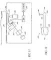
- FIG. 1is a schematic view of a noninvasive optical detection system.
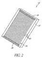
- FIG. 2is a perspective view of a window assembly for use with the noninvasive detection system.
- FIG. 3is an exploded schematic view of an alternative window assembly for use with the noninvasive detection system.
- FIG. 4is a plan view of the window assembly connected to a cooling system.
- FIG. 5is a plan view of the window assembly connected to a cold reservoir.
- FIG. 6is a cutaway view of a heat sink for use with the noninvasive detection system.
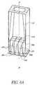
- FIG. 6Ais a cutaway perspective view of a lower portion of the noninvasive detection system of FIG. 1 .
- FIG. 7is a schematic view of a control system for use with the noninvasive optical detection system.
- FIG. 8depicts a first methodology for determining the concentration of an analyte of interest.
- FIG. 9depicts a second methodology for determining the concentration of an analyte of interest.
- FIG. 10depicts a third methodology for determining the concentration of an analyte of interest.
- FIG. 11depicts a fourth methodology for determining the concentration of an analyte of interest.
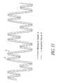
- FIG. 12depicts a fifth methodology for determining the concentration of an analyte of interest.
- FIG. 13is a schematic view of a reagentless whole-blood detection system.
- FIG. 14is a perspective view of one embodiment of a cuvette for use with the reagentless whole-blood detection system.
- FIG. 15is a plan view of another embodiment of a cuvette for use with the reagentless whole-blood detection system.
- FIG. 16is a disassembled plan view of the cuvette shown in FIG. 15 .
- FIG. 16Ais an exploded perspective view of the cuvette of FIG. 15 .
- FIG. 17is a side view of the cuvette of FIG. 15 .
- FIG. 18is a schematic view of a reagentless whole-blood detection system having a communication port for connecting the system to other devices or networks.
- FIG. 18Ais a schematic view of a reagentless whole-blood detection system having a noninvasive subsystem and a whole-blood subsystem.
- FIG. 19is a schematic view of a filter wheel incorporated into some embodiments of the whole-blood system of FIG. 13 .
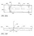
- FIG. 20Ais a top plan view of another embodiment of a whole-blood strip cuvette.
- FIG. 20Bis a side view of the whole-blood strip cuvette of FIG. 20A .
- FIG. 20Cis an exploded view of the embodiment of the whole-blood strip cuvette of FIG. 20A .
- FIG. 21is process flow chart illustrating a method for making another embodiment of a whole-blood strip cuvette.
- FIG. 22is a schematic illustration of a cuvette handler for packaging whole-blood strip cuvettes made according to the process of FIG. 21 for the system of FIG. 13 .
- FIG. 23Ais a schematic illustration of a whole-blood strip cuvette having one type of flow enhancer.
- FIG. 23Bis a schematic illustration of a whole-blood strip cuvette having another type of flow enhancer.
- FIG. 24Ais a side view of a whole-blood strip cuvette with another type of flow enhancer.
- FIG. 24Bis a cross sectional view of the whole-blood strip cuvette of FIG. 24A showing the structure of one type of flow enhancer.
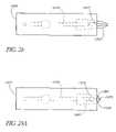
- FIG. 25is a schematic illustration of another embodiment of a reagentless whole-blood detection system.
- FIG. 26is a schematic illustration of another embodiment of a reagentless whole-blood detection system.
- FIG. 27is a schematic illustration of a cuvette configured for calibration.
- FIG. 28is a plan view of one embodiment of a cuvette having an integrated lance.
- FIG. 28Ais a plan view of another embodiment of a cuvette having an integrated lance.
- FIG. 29is a plan view of another embodiment of a cuvette having an integrated lance.
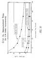
- FIG. 30is a graph of the measurement accuracy of the whole-blood analyte detection system versus measurement time.
- FIG. 31is a perspective view of another embodiment of a sample element having an integrated lancing member.
- FIG. 32is a perspective view of a distal end of the sample element of FIG. 31 .
- FIG. 32Ais a cross-sectional view of the distal end of FIG. 32 , taken along line 32 A— 32 A.
- FIG. 32Bis a cross-sectional view of the distal end of FIG. 32 , taken along line 32 B— 32 B.
- FIG. 32Cis a cross-sectional view of a portion of the distal end of FIG. 32B , illustrating an optical path through a chamber located in the distal end.
- FIG. 33is an exploded perspective view of the sample element of FIG. 31 .
- FIGS. 34A–34Bare perspective views of another embodiment of a sample element having an integrated lancing member.
- FIG. 35is a perspective view of another embodiment of a sample element having an integrated sample extractor.
- analyte detection systemsincluding a noninvasive system discussed largely in part A below and a whole-blood system discussed largely in part B below.
- various methodsincluding methods for detecting the concentration of an analyte in a material sample.
- the noninvasive system/method and the whole-blood system/methodare related in that they both can employ optical measurement.
- opticalis a broad term and is used in its ordinary sense and refers, without limitation, to identification of the presence or concentration of an analyte in a material sample without requiring a chemical reaction to take place.
- the two approacheseach can operate independently to perform an optical analysis of a material sample.
- the two approachescan also be combined in an apparatus, or the two approaches can be used together to perform different steps of a method.
- the two approachesare combined to perform calibration of an apparatus, e.g., of an apparatus that employs a noninvasive approach.
- an advantageous combination of the two approachesperforms an invasive measurement to achieve greater accuracy and a whole-blood measurement to minimize discomfort to the patient.
- the whole-blood techniquemay be more accurate than the noninvasive technique at certain times of the day, e.g., at certain times after a meal has been consumed, or after a drug has been administered.
- any of the disclosed devicesmay be operated in accordance with any suitable detection methodology, and that any disclosed method may be employed in the operation of any suitable device.
- the disclosed devices and methodsare applicable in a wide variety of situations or modes of operation, including but not limited to invasive, noninvasive, intermittent or continuous measurement, subcutaneous implantation, wearable detection systems, or any combination thereof.
- FIG. 1depicts a noninvasive optical detection system (hereinafter “noninvasive system”) 10 in a presently preferred configuration.
- the depicted noninvasive system 10is particularly suited for noninvasively detecting the concentration of an analyte in a material sample S, by observing the infrared energy emitted by the sample, as will be discussed in further detail below.
- noninvasiveis a broad term and is used in its ordinary sense and refers, without limitation, to analyte detection devices and methods which have the capability to determine the concentration of an analyte in in-vivo tissue samples or bodily fluids. It should be understood, however, that the noninvasive system 10 disclosed herein is not limited to noninvasive use, as the noninvasive system 10 may be employed to analyze an in-vitro fluid or tissue sample which has been obtained invasively or noninvasively.
- invasiveis a broad term and is used in its ordinary sense and refers, without limitation, to analyte detection methods which involve the removal of fluid samples through the skin.
- the term “material sample”is a broad term and is used in its ordinary sense and refers, without limitation, to any collection of material which is suitable for analysis by the noninvasive system 10 .
- the material sample Smay comprise a tissue sample, such as a human forearm, placed against the noninvasive system 10 .
- the material sample Smay also comprise a volume of a bodily fluid, such as whole blood, blood component(s), interstitial fluid or intercellular fluid obtained invasively, or saliva or urine obtained noninvasively, or any collection of organic or inorganic material.
- analyteis a broad term and is used in its ordinary sense and refers, without limitation, to any chemical species the presence or concentration of which is sought in the material sample S by the noninvasive system 10 .
- the analyte(s) which may be detected by the noninvasive system 10include but not are limited to glucose, ethanol, insulin, water, carbon dioxide, blood oxygen, cholesterol, bilirubin, ketones, fatty acids, lipoproteins, albumin, urea, creatinine, white blood cells, red blood cells, hemoglobin, oxygenated hemoglobin, carboxyhemoglobin, organic molecules, inorganic molecules, pharmaceuticals, cytochrome, various proteins and chromophores, microcalcifications, electrolytes, sodium, potassium, chloride, bicarbonate, and hormones.
- the term “continuous”is a broad term and is used in its ordinary sense and refers, without limitation, to the taking of discrete measurements more frequently than about once every 10 minutes, and/or the taking of a stream or series of measurements or other data over any suitable time interval, for example, over an interval of one to several seconds, minutes, hours, days, or longer.
- the term “intermittent”is a broad term and is used in its ordinary sense and refers, without limitation, to the taking of measurements less frequently than about once every 10 minutes.
- the noninvasive system 10preferably comprises a window assembly 12 , although in some embodiments the window assembly 12 may be omitted.
- One function of the window assembly 12is to permit infrared energy E to enter the noninvasive system 10 from the sample S when it is placed against an upper surface 12 a of the window assembly 12 .
- the window assembly 12includes a heater layer (see discussion below) which is employed to heat the material sample S and stimulate emission of infrared energy therefrom.
- a cooling system 14preferably comprising a Peltier-type thermoelectric device, is in thermally conductive relation to the window assembly 12 so that the temperature of the window assembly 12 and the material sample S can be manipulated in accordance with a detection methodology discussed in greater detail below.
- the cooling system 14includes a cold surface 14 a which is in thermally conductive relation to a cold reservoir 16 and the window assembly 12 , and a hot surface 14 b which is in thermally conductive relation to a heat sink 18 .
- the infrared energy EAs the infrared energy E enters the noninvasive system 10 , it first passes through the window assembly 12 , then through an optical mixer 20 , and then through a collimator 22 .
- the optical mixer 20preferably comprises a light pipe having highly reflective inner surfaces which randomize the directionality of the infrared energy E as it passes therethrough and reflects against the mixer walls.
- the collimator 22also comprises a light pipe having highly-reflective inner walls, but the walls diverge as they extend away from the mixer 20 . The divergent walls cause the infrared energy E to tend to straighten as it advances toward the wider end of the collimator 22 , due to the angle of incidence of the infrared energy when reflecting against the collimator walls.
- each filter 24is preferably in optical communication with a concentrator 26 and an infrared detector 28 .
- the concentrators 26have highly reflective, converging inner walls which concentrate the infrared energy as it advances toward the detectors 28 , increasing the density of the energy incident upon the detectors 28 .
- the detectors 28are in electrical communication with a control system 30 which receives electrical signals from the detectors 28 and computes the concentration of the analyte in the sample S.
- the control system 30is also in electrical communication with the window 12 and cooling system 14 , so as to monitor the temperature of the window 12 and/or cooling system 14 and control the delivery of electrical power to the window 12 and cooling system 14 .
- the window assembly 12generally comprises a main layer 32 formed of a highly infrared-transmissive material and a heater layer 34 affixed to the underside of the main layer 32 .
- the main layer 32is preferably formed from diamond, most preferably from chemical-vapor-deposited (“CVD”) diamond, with a preferred thickness of about 0.25 millimeters.
- CVDchemical-vapor-deposited
- alternative materials which are highly infrared-transmissive, such as silicon or germanium,may be used in forming the main layer 32 .
- the heater layer 34preferably comprises bus bars 36 located at opposing ends of an array of heater elements 38 .
- the bus bars 36are in electrical communication with the elements 38 so that, upon connection of the bus bars 36 to a suitable electrical power source (not shown) a current may be passed through the elements 38 to generate heat in the window assembly 12 .
- the heater layer 34may also include one or more temperature sensors (not shown), such as thermistors or resistance temperature devices (RTDs), to measure the temperature of the window assembly 12 and provide temperature feedback to the control system 30 (see FIG. 1 ).
- the heater layer 34preferably comprises a first adhesion layer of gold or platinum (hereinafter referred to as the “gold” layer) deposited over an alloy layer which is applied to the main layer 32 .
- the alloy layercomprises a material suitable for implementation of the heater layer 34 , such as, by way of example, 10/90 titanium/tungsten, titanium/platinum, nickel/chromium, or other similar material.
- the gold layerpreferably has a thickness of about 4000 ⁇ , and the alloy layer preferably has a thickness ranging between about 300 ⁇ and about 500 ⁇ .
- the gold layer and/or the alloy layermay be deposited onto the main layer 32 by chemical deposition including, but not necessarily limited to, vapor deposition, liquid deposition, plating, laminating, casting, sintering, or other forming or deposition methodologies well known to those or ordinary skill in the art.
- the heater layer 34may be covered with an electrically insulating coating which also enhances adhesion to the main layer 32 .
- One preferred coating materialis aluminum oxide.
- Other acceptable materialsinclude, but are not limited to, titanium dioxide or zinc selenide.
- the heater layer 34may incorporate a variable pitch distance between centerlines of adjacent heater elements 38 to maintain a constant power density, and promote a uniform temperature, across the entire layer 34 . Where a constant pitch distance is employed, the preferred distance is at least about 50–100 microns. Although the heater elements 38 generally have a preferred width of about 25 microns, their width may also be varied as needed for the same reasons stated above.
- heater layer 34Alternative structures suitable for use as the heater layer 34 include, but are not limited to, thermoelectric heaters, radiofrequency (RF) heaters, infrared radiation heaters, optical heaters, heat exchangers, electrical resistance heating grids, wire bridge heating grids, or laser heaters. Whichever type of heater layer is employed, it is preferred that the heater layer obscures about 10% or less of the window assembly 12 .
- RFradiofrequency
- the window assembly 12comprises substantially only the main layer 32 and the heater layer 34 .
- the window assembly 12when installed in an optical detection system such as the noninvasive system 10 shown in FIG. 1 , the window assembly 12 will facilitate a minimally obstructed optical path between a (preferably flat) upper surface 12 a of the window assembly 12 and the infrared detectors 28 of the noninvasive system 10 .
- the optical path 32 in the preferred noninvasive system 10proceeds only through the main layer 32 and heater layer 34 of the window assembly 12 (including any antireflective, index-matching, electrical insulating or protective coatings applied thereto or placed therein), through the optical mixer 20 and collimator 22 and to the detectors 28 .
- FIG. 3depicts an exploded side view of an alternative configuration for the window assembly 12 , which may be used in place of the configuration shown in FIG. 2 .
- the window assembly 12 depicted in FIG. 3includes near its upper surface (the surface intended for contact with the sample S) a highly infrared-transmissive, thermally conductive spreader layer 42 . Underlying the spreader layer 42 is a heater layer 44 .
- a thin electrically insulating layer(not shown), such as layer of aluminum oxide, titanium dioxide or zinc selenide, may be disposed between the heater layer 44 and the spreader layer 42 .
- Adjacent to the heater layer 44is a thermal insulating and impedance matching layer 46 .
- Adjacent to the thermal insulating layer 46is a thermally conductive inner layer 48 .
- the spreader layer 42is coated on its top surface with a thin layer of protective coating 50 .
- the bottom surface of the inner layer 48is coated with a thin overcoat layer 52 .
- the protective coating 50 and the overcoat layer 52have antireflective properties.
- the spreader layer 42is preferably formed of a highly infrared-transmissive material having a high thermal conductivity sufficient to facilitate heat transfer from the heater layer 44 uniformly into the material sample S when it is placed against the window assembly 12 .
- Other effective materialsinclude, but are not limited to, CVD diamond, diamondlike carbon, gallium arsenide, germanium, and other infrared-transmissive materials having sufficiently high thermal conductivity.
- Preferred dimensions for the spreader layer 42are about one inch in diameter and about 0.010 inch thick. As shown in FIG. 3 , a preferred embodiment of the spreader layer 42 incorporates a beveled edge. Although not required, an approximate 45-degree bevel is preferred.
- the protective layer 50is intended to protect the top surface of the spreader layer 42 from damage.
- the protective layeris highly infrared-transmissive and highly resistant to mechanical damage, such as scratching or abrasion. It is also preferred that the protective layer 50 and the overcoat layer 52 have high thermal conductivity and antireflective and/or index-matching properties.
- a satisfactory material for use as the protective layer 50 and the overcoat layer 52is the multi-layer Broad Band Anti-Reflective Coating produced by Deposition Research Laboratories, Inc. of St. Charles, Mo. Diamondlike carbon coatings are also suitable.
- the heater layer 44is generally similar to the heater layer 34 employed in the window assembly shown in FIG. 2 .
- the heater layer 44may comprise a doped infrared-transmissive material, such as a doped silicon layer, with regions of higher and lower resistivity.
- the heater layer 44preferably has a resistance of about 2 ohms and has a preferred thickness of about 1,500 angstroms.
- a preferred material for forming the heater layer 44is a gold alloy, but other acceptable materials include, but are not limited to, platinum, titanium, tungsten, copper, and nickel.
- the thermal insulating layer 46prevents the dissipation of heat from the heater element 44 while allowing the cooling system 14 to effectively cool the material sample S (see FIG. 1 ).
- This layer 46comprises a material having thermally insulative (e.g., lower thermal conductivity than the spreader layer 42 ) and infrared transmissive qualities.
- a preferred materialis a germanium-arsenic-selenium compound of the calcogenide glass family known as AMTIR-1 produced by Amorphous Materials, Inc. of Garland, Tex.
- the pictured embodimenthas a diameter of about 0.85 inches and a preferred thickness in the range of about 0.005 to about 0.010 inches. As heat generated by the heater layer 44 passes through the spreader layer 42 into the material sample S, the thermal insulating layer 46 insulates this heat.
- the inner layer 48is formed of thermally conductive material, preferably crystalline silicon formed using a conventional floatzone crystal growth method.
- the purpose of the inner layer 48is to serve as a cold-conducting mechanical base for the entire layered window assembly.
- the overall optical transmission of the window assembly 12 shown in FIG. 3is preferably at least 70%.
- the window assembly 12 of FIG. 3is preferably held together and secured to the noninvasive system 10 by a holding bracket (not shown).
- the bracketis preferably formed of a glass-filled plastic, for example Ultem 2300, manufactured by General Electric. Ultem 2300 has low thermal conductivity which prevents heat transfer from the layered window assembly 12 .
- the cooling system 14(see FIG. 1 ) preferably comprises a Peltier-type thermoelectric device.
- the cooling system 14cools the window assembly 12 via the situation of the window assembly 12 in thermally conductive relation to the cold surface 14 a of the cooling system 14 .
- the cooling system 14 , the heater layer 34 , or bothcan be operated to induce a desired time-varying temperature in the window assembly 12 to create an oscillating thermal gradient in the sample S, in accordance with various analyte-detection methodologies discussed herein.
- the cold reservoir 16is positioned between the cooling system 14 and the window assembly 12 , and functions as a thermal conductor between the system 14 and the window assembly 12 .
- the cold reservoir 16is formed from a suitable thermally conductive material, preferably brass.
- the window assembly 12can be situated in direct contact with the cold surface 14 a of the cooling system 14 .
- the cooling system 14may comprise a heat exchanger through which a coolant, such as air, nitrogen or chilled water, is pumped, or a passive conduction cooler such as a heat sink.
- a gas coolantsuch as nitrogen may be circulated through the interior of the noninvasive system 10 so as to contact the underside of the window assembly 12 (see FIG. 1 ) and conduct heat therefrom.
- FIG. 4is a top schematic view of a preferred arrangement of the window assembly 12 (of the type shown in FIG. 2 ) and the cold reservoir 16
- FIG. 5is a top schematic view of an alternative arrangement in which the window assembly 12 directly contacts the cooling system 14
- the cold reservoir 16 /cooling system 14preferably contacts the underside of the window assembly 12 along opposing edges thereof, on either side of the heater layer 34 . With thermal conductivity thus established between the window assembly 12 and the cooling system 14 , the window assembly can be cooled as needed during operation of the noninvasive system 10 .
- the pitch distance between centerlines of adjacent heater elements 38may be made smaller (thereby increasing the density of heater elements 38 ) near the region(s) of contact between the window assembly 12 and the cold reservoir 16 /cooling system 14 .
- the heater elements 38themselves may be made wider near these regions of contact.
- isothermalis a broad term and is used in its ordinary sense and refers, without limitation, to a condition in which, at a given point in time, the temperature of the window assembly 12 or other structure is substantially uniform across a surface intended for placement in thermally conductive relation to the material sample S.
- the temperature of the structure or surfacemay fluctuate over time, at any given point in time the structure or surface may nonetheless be isothermal.
- the heat sink 18drains waste heat from the hot surface 14 b of the cooling system 16 and stabilizes the operational temperature of the noninvasive system 10 .
- the preferred heat sink 18(see FIG. 6 ) comprises a hollow structure formed from brass or any other suitable material having a relatively high specific heat and high heat conductivity.
- the heat sink 18has a conduction surface 18 a which, when the heat sink 18 is installed in the noninvasive system 18 , is in thermally conductive relation to the hot surface 14 b of the cooling system 14 (see FIG. 1 ).
- a cavity 54is formed in the heat sink 18 and preferably contains a phase-change material (not shown) to increase the capacity of the sink 18 .
- a preferred phase change materialis a hydrated salt, such as calciumchloride hexahydrate, available under the name TH29 from PCM Thermal Solutions, Inc., of Naperville, Ill.
- the cavity 54may be omitted to create a heat sink 18 comprising a solid, unitary mass.
- the heat sink 18also forms a number of fins 56 to further increase the conduction of heat from the sink 18 to surrounding air.
- the heat sink 18may be formed integrally with the optical mixer 20 and/or the collimator 22 as a unitary mass of rigid, heat-conductive material such as brass or aluminum.
- the mixer 20 and/or collimator 22extend axially through the heat sink 18 , and the heat sink defines the inner walls of the mixer 20 and/or collimator 22 .
- These inner wallsare coated and/or polished to have appropriate reflectivity and nonabsorbance in infrared wavelengths as will be further described below.
- any suitable structuremay be employed to heat and/or cool the material sample S, instead of or in addition to the window assembly 12 /cooling system 14 disclosed above, so long a proper degree of cycled heating and/or cooling are imparted to the material sample S.
- other forms of energysuch as but not limited to light, radiation, chemically induced heat, friction and vibration, may be employed to heat the material sample S.
- heating of the samplecan achieved by any suitable method, such as convection, conduction, radiation, etc.
- the optical mixer 20comprises a light pipe with an inner surface coating which is highly reflective and minimally absorptive in infrared wavelengths, preferably a polished gold coating, although other suitable coatings may be used where other wavelengths of electromagnetic radiation are employed.
- the pipeitself may be fabricated from a another rigid material such as aluminum or stainless steel, as long as the inner surfaces are coated or otherwise treated to be highly reflective.
- the optical mixer 20has a rectangular cross-section (as taken orthogonal to the longitudinal axis A-A of the mixer 20 and the collimator 22 ), although other cross-sectional shapes, such as other polygonal shapes or circular or elliptical shapes, may be employed in alternative embodiments.
- the inner walls of the optical mixer 20are substantially parallel to the longitudinal axis A-A of the mixer 20 and the collimator 22 .
- the highly reflective and substantially parallel inner walls of the mixer 20maximize the number of times the infrared energy E will be reflected between the walls of the mixer 20 , thoroughly mixing the infrared energy E as it propagates through the mixer 20 .
- the mixer 20is about 1.2 inches to 2.4 inches in length and its cross-section is a rectangle of about 0.4 inches by about 0.6 inches.
- other dimensionsmay be employed in constructing the mixer 20 . In particular it is be advantageous to miniaturize the mixer or otherwise make it as small as possible
- the collimator 22comprises a tube with an inner surface coating which is highly reflective and minimally absorptive in infrared wavelengths, preferably a polished gold coating.
- the tubeitself may be fabricated from a another rigid material such as aluminum, nickel or stainless steel, as long as the inner surfaces are coated or otherwise treated to be highly reflective.
- the collimator 22has a rectangular cross-section, although other cross-sectional shapes, such as other polygonal shapes or circular, parabolic or elliptical shapes, may be employed in alternative embodiments.
- the inner walls of the collimator 22diverge as they extend away from the mixer 20 .
- the inner walls of the collimator 22are substantially straight and form an angle of about 7 degrees with respect to the longitudinal axis A-A.
- the collimator 22aligns the infrared energy E to propagate in a direction that is generally parallel to the longitudinal axis A-A of the mixer 20 and the collimator 22 , so that the infrared energy E will strike the surface of the filters 24 at an angle as close to 90 degrees as possible.
- the collimatoris about 7.5 inches in length.
- the cross-section of the collimator 22is a rectangle of about 0.4 inches by 0.6 inches.
- the collimator 22has a rectangular cross-section of about 1.8 inches by 2.6 inches.
- the collimator 22aligns the infrared energy E to an angle of incidence (with respect to the longitudinal axis A-A) of about 0–15 degrees before the energy E impinges upon the filters 24 .
- angle of incidencewith respect to the longitudinal axis A-A
- other dimensions or incidence anglesmay be employed in constructing and operating the collimator 22 .
- each concentrator 26comprises a tapered surface oriented such that its wide end 26 a is adapted to receive the infrared energy exiting the corresponding filter 24 , and such that its narrow end 26 b is adjacent to the corresponding detector 28 .
- the inward-facing surfaces of the concentrators 26have an inner surface coating which is highly reflective and minimally absorptive in infrared wavelengths, preferably a polished gold coating.
- the concentrators 26themselves may be fabricated from a another rigid material such as aluminum, nickel or stainless steel, so long as their inner surfaces are coated or otherwise treated to be highly reflective.
- the concentrators 26have a rectangular cross-section (as taken orthogonal to the longitudinal axis A-A), although other cross-sectional shapes, such as other polygonal shapes or circular, parabolic or elliptical shapes, may be employed in alternative embodiments.
- the inner walls of the concentratorsconverge as they extend toward the narrow end 26 b .
- the inner walls of the collimators 26are substantially straight and form an angle of about 8 degrees with respect to the longitudinal axis A-A.
- Such a configurationis adapted to concentrate infrared energy as it passes through the concentrators 26 from the wide end 26 a to the narrow end 26 b , before reaching the detectors 28 .
- each concentrator 26is about 1.5 inches in length.
- the cross-section of each concentrator 26is a rectangle of about 0.6 inches by 0.57 inches.
- each concentrator 26has a rectangular cross-section of about 0.177 inches by 0.177 inches.
- other dimensions or incidence anglesmay be employed in constructing the concentrators 26 .
- the filters 24preferably comprise standard interference-type infrared filters, widely available from manufacturers such as Optical Coating Laboratory, Inc. (“OCLI”) of Santa Rosa, Calif.
- OCLIOptical Coating Laboratory, Inc.
- a 3 ⁇ 4 array of filters 24is positioned above a 3 ⁇ 4 array of detectors 28 and concentrators 26 .
- the filters 24are arranged in four groups of three filters having the same wavelength sensitivity. These four groups have bandpass center wavelengths of 7.15 ⁇ m ⁇ 0.03 ⁇ m, 8.40 ⁇ m ⁇ 0.03 ⁇ m, 9.48 ⁇ m ⁇ 0.04 ⁇ m, and 11.10 ⁇ m ⁇ 0.04 ⁇ m, respectively, which correspond to wavelengths around which water and glucose absorb electromagnetic radiation. Typical bandwidths for these filters range from 0.20 ⁇ m to 0.50 ⁇ m.
- the array of wavelength-specific filters 24may be replaced with a single Fabry-Perot interferometer, which can provide wavelength sensitivity which varies as a sample of infrared energy is taken from the material sample S.
- this embodimentpermits the use of only one detector 28 , the output signal of which varies in wavelength specificity over time.
- the output signalcan be de-multiplexed based on the wavelength sensitivities induced by the Fabry-Perot interferometer, to provide a multiple-wavelength profile of the infrared energy emitted by the material sample S.
- the optical mixer 20may be omitted, as only one detector 28 need be employed.
- the array of filters 24may comprise a filter wheel that rotates different filters with varying wavelength sensitivities over a single detector 24 .
- an electronically tunable infrared filtermay be employed in a manner similar to the Fabry-Perot interferometer discussed above, to provide wavelength sensitivity which varies during the detection process.
- the optical mixer 20may be omitted, as only one detector 28 need be employed.
- the detectors 28may comprise any detector type suitable for sensing infrared energy, preferably in the mid-infrared wavelengths.
- the detectors 28may comprise mercury-cadmium-telluride (MCT) detectors.
- MCTmercury-cadmium-telluride
- a detectorsuch as a Fermionics (Simi Valley, Calif.) model PV-9.1 with a PVA481-1 pre-amplifier is acceptable. Similar units from other manufacturers such as Graseby (Tampa, Fla.) can be substituted.
- Other suitable components for use as the detectors 28include pyroelectric detectors, thermopiles, bolometers, silicon microbolometers and lead-salt focal plane arrays.
- FIG. 7depicts the control system 30 in greater detail, as well as the interconnections between the control system and other relevant portions of the noninvasive system.
- the control systemincludes a temperature control subsystem and a data acquisition subsystem.
- temperature sensorssuch as RTDs and/or thermistors located in the window assembly 12 provide a window temperature signal to a synchronous analog-to-digital conversion system 70 and an asynchronous analog-to-digital conversion system 72 .
- the A/D systems 70 , 72in turn provide a digital window temperature signal to a digital signal processor (DSP) 74 .
- DSPdigital signal processor
- the processor 74executes a window temperature control algorithm and determines appropriate control inputs for the heater layer 34 of the window assembly 12 and/or for the cooling system 14 , based on the information contained in the window temperature signal.
- the processor 74outputs one or more digital control signals to a digital-to-analog conversion system 76 which in turn provides one or more analog control signals to current drivers 78 .
- the current drivers 78regulate the power supplied to the heater layer 34 and/or to the cooling system 14 .
- the processor 74provides a control signal through a digital I/O device 77 to a pulse-width modulator (PWM) control 80 , which provides a signal that controls the operation of the current drivers 78 .
- PWMpulse-width modulator
- a low-pass filter(not shown) at the output of the PWM provides for continuous operation of the current drivers 78 .
- temperature sensorsmay be located at the cooling system 14 and appropriately connected to the A/D system(s) and processor to provide closed-loop control of the cooling system as well.
- a detector cooling system 82is located in thermally conductive relation to one or more of the detectors 28 .
- the detector cooling system 82may comprise any of the devices disclosed above as comprising the cooling system 14 , and preferably comprises a Peltier-type thermoelectric device.
- the temperature control subsystemmay also include temperature sensors, such as RTDs and/or thermistors, located in or adjacent to the detector cooling system 82 , and electrical connections between these sensors and the asynchronous A/D system 72 .
- the temperature sensors of the detector cooling system 82provide detector temperature signals to the processor 74 .
- the detector cooling system 82operates independently of the window temperature control system, and the detector cooling system temperature signals are sampled using the asynchronous A/D system 72 .
- the processor 74determines appropriate control inputs for the detector cooling system 82 , based on the information contained in the detector temperature signal.
- the processor 74outputs digital control signals to the D/A system 76 which in turn provides analog control signals to the current drivers 78 .
- the current drivers 78regulate the power supplied to the detector cooling system 14 .
- the processor 74also provides a control signal through the digital I/O device 77 and the PWM control 80 , to control the operation of the detector cooling system 82 by the current drivers 78 .
- a low-pass filter(not shown) at the output of the PWM provides for continuous operation of the current drivers 78 .
- the detectors 28respond to the infrared energy E incident thereon by passing one or more analog detector signals to a preamp 84 .
- the preamp 84amplifies the detector signals and passes them to the synchronous A/D system 70 , which converts the detector signals to digital form and passes them to the processor 74 .
- the processor 74determines the concentrations of the analyte(s) of interest, based on the detector signals and a concentration-analysis algorithm and/or phase/concentration regression model stored in a memory module 88 .
- the concentration-analysis algorithm and/or phase/concentration regression modelmay be developed according to any of the analysis methodologies discussed herein.
- the processormay communicate the concentration results and/or other information to a display controller 86 , which operates a display (not shown), such as an LCD display, to present the information to the user.
- a watchdog timer 94may be employed to ensure that the processor 74 is operating correctly. If the watchdog timer 94 does not receive a signal from the processor 74 within a specified time, the watchdog timer 94 resets the processor 74 .
- the control systemmay also include a JTAG interface 96 to enable testing of the noninvasive system 10 .
- the synchronous A/D system 70comprises a 20-bit, 14 channel system
- the asynchronous A/D system 72comprises a 16-bit, 16 channel system.
- the preampmay comprise a 12-channel preamp corresponding to an array of 12 detectors 28 .
- the control systemmay also include a serial port 90 or other conventional data port to permit connection to a personal computer 92 .
- the personal computercan be employed to update the algorithm(s) and/or phase/concentration regression model(s) stored in the memory module 88 , or to download a compilation of analyte-concentration data from the noninvasive system.
- a real-time clock or other timing devicemay be accessible by the processor 74 to make any time-dependent calculations which may be desirable to a user.
- the detector(s) 28 of the noninvasive system 10are used to detect the infrared energy emitted by the material sample S in various desired wavelengths. At each measured wavelength, the material sample S emits infrared energy at an intensity which varies over time. The time-varying intensities arise largely in response to the use of the window assembly 12 (including its heater layer 34 ) and the cooling system 14 to induce a thermal gradient in the material sample S.
- thermal gradientis a broad term and is used in its ordinary sense and refers, without limitation, to a difference in temperature and/or thermal energy between different locations, such as different depths, of a material sample, which can be induced by any suitable method of increasing or decreasing the temperature and/or thermal energy in one or more locations of the sample.
- concentration of an analyte of interestsuch as glucose
- the concentration of an analyte of interestcan be determined with a device such as the noninvasive system 10 , by comparing the time-varying intensity profiles of the various measured wavelengths.
- a first reference signal Pmay be measured at a first reference wavelength.
- the first reference signal Pis measured at a wavelength where water strongly absorbs (e.g., 2.9 ⁇ m or 6.1 ⁇ m). Because water strongly absorbs radiation at these wavelengths, the detector signal intensity is reduced at those wavelengths. Moreover, at these wavelengths water absorbs the photon emissions emanating from deep inside the sample. The net effect is that a signal emitted at these wavelengths from deep inside the sample is not easily detected.
- the first reference signal Pis thus a good indicator of thermal-gradient effects near the sample surface and may be known as a surface reference signal. This signal may be calibrated and normalized, in the absence of heating or cooling applied to the sample, to a baseline value of 1. For greater accuracy, more than one first reference wavelength may be measured. For example, both 2.9 ⁇ m and 6.1 ⁇ m may be chosen as first reference wavelengths.
- a second reference signal Rmay also be measured.
- the second signal Rmay be measured at a wavelength where water has very low absorbance (e.g., 3.6 ⁇ m or 4.2 ⁇ m).
- This second reference signal Rthus provides the analyst with information concerning the deeper regions of the sample, whereas the first signal P provides information concerning the sample surface.
- This signalmay also be calibrated and normalized, in the absence of heating or cooling applied to the sample, to a baseline value of 1. As with the first (surface) reference signal P, greater accuracy may be obtained by using more than one second (deep) reference signal R.
- a third (analytical) signal Qis also measured.
- This signalis measured at an IR absorbance peak of the selected analyte.
- the IR absorbance peaks for glucoseare in the range of about 6.5 ⁇ m to 11.0 ⁇ m.
- This detector signalmay also be calibrated and normalized, in the absence of heating or cooling applied to the material sample S, to a baseline value of 1.
- the analytical signal Qmay be measured at more than one absorbance peak.
- reference signalsmay be measured at wavelengths that bracket the analyte absorbance peak. These signals may be advantageously monitored at reference wavelengths which do not overlap the analyte absorbance peaks. Further, it is advantageous to measure reference wavelengths at absorbance peaks which do not overlap the absorbance peaks of other possible constituents contained in the sample.
- the signal intensities P, Q, Rare shown initially at the normalized baseline signal intensity of 1. This of course reflects the baseline radiative behavior of a test sample in the absence of applied heating or cooling.
- the surface of the sampleis subjected to a temperature event which induces a thermal gradient in the sample.
- the gradientcan be induced by heating or cooling the sample surface.
- the example shown in FIG. 8uses cooling, for example, using a 10° C. cooling event.
- the intensities of the detector signals P, Q, Rdecrease over time.
- the surfacecools before the deeper regions of the sample cool.
- the signals P, Q, Rdrop in intensity, a pattern emerges. Signal intensity declines as expected, but as the signals P, Q, R reach a given amplitude value (or series of amplitude values: 150 , 152 , 154 , 156 , 158 ), certain temporal effects are noted.
- the first (surface) reference signal Pdeclines in amplitude most rapidly, reaching a checkpoint 150 first, at time t P . This is due to the fact that the first reference signal P mirrors the sample's radiative characteristics near the surface of the sample. Since the sample surface cools before the underlying regions, the surface (first) reference signal P drops in intensity first.
- the second reference signal Ris monitored. Since the second reference signal R corresponds to the radiation characteristics of deeper regions of the sample, which do not cool as rapidly as the surface (due to the time needed for the surface cooling to propagate into the deeper regions of the sample), the intensity of signal R does not decline until slightly later. Consequently, the signal R does not reach the magnitude 150 until some later time t R . In other words, there exists a time delay between the time t P at which the amplitude of the first reference signal P reaches the checkpoint 150 and the time t R at which the second reference signal R reaches the same checkpoint 150 . This time delay can be expressed as a phase difference ⁇ ( ⁇ ). Additionally, a phase difference may be measured between the analytical signal Q and either or both reference signals P, R.
- the concentration of analyteincreases. This reduces the intensity of the analytical signal Q in a concentration-dependent way. Consequently, the analytical signal Q reaches intensity 150 at some intermediate time t Q .
- the higher the concentration of analytethe more the analytical signal Q shifts to the left in FIG. 8 .
- the phase difference ⁇ ( ⁇ )decreases relative to the first (surface) reference signal P and increases relative to the second (deep tissue) reference signal R.
- the phase difference(s) ⁇ ( ⁇ )are directly related to analyte concentration and can be used to make accurate determinations of analyte concentration.
- the magnitude of this phase differencedecreases with increasing analyte concentration.
- the magnitude of this phase differenceincreases with increasing analyte concentration.
- Accuracymay be enhanced by choosing several checkpoints, for example, 150 , 152 , 154 , 156 , and 158 and averaging the phase differences observed at each checkpoint.
- the accuracy of this methodmay be further enhanced by integrating the phase difference(s) continuously over the entire test period. Because in this example only a single temperature event (here, a cooling event) has been induced, the sample reaches a new lower equilibrium temperature and the signals stabilize at a new constant level I F .
- the methodworks equally well with thermal gradients induced by heating or by the application or introduction of other forms of energy, such as but not limited to light, radiation, chemically induced heat, friction and vibration.
- This methodologyis not limited to the determination of phase difference.
- the amplitude of the analytical signal Qmay be compared to the amplitude of either or both of the reference signals P, R.
- the difference in amplitudemay be observed and processed to determine analyte concentration.
- This method, the variants disclosed herein, and the apparatus disclosed as suitable for application of the method(s),are not limited to the detection of in-vivo glucose concentration.
- the method and disclosed variants and apparatusmay be used on human, animal, or even plant subjects, or on organic or inorganic compositions in a non-medical setting.
- the methodmay be used to take measurements of in-vivo or in-vitro samples of virtually any kind.
- the methodis useful for measuring the concentration of a wide range of additional chemical analytes, including but not limited to, glucose, ethanol, insulin, water, carbon dioxide, blood oxygen, cholesterol, bilirubin, ketones, fatty acids, lipoproteins, albumin, urea, creatinine, white blood cells, red blood cells, hemoglobin, oxygenated hemoglobin, carboxyhemoglobin, organic molecules, inorganic molecules, pharmaceuticals, cytochrome, various proteins and chromophores, microcalcifications, hormones, as well as other chemical compounds.
- additional chemical analytesincluding but not limited to, glucose, ethanol, insulin, water, carbon dioxide, blood oxygen, cholesterol, bilirubin, ketones, fatty acids, lipoproteins, albumin, urea, creatinine, white blood cells, red blood cells, hemoglobin, oxygenated hemoglobin, carboxyhemoglobin, organic molecules, inorganic molecules, pharmaceuticals, cytochrome, various proteins and chromophores, microcalcifications, hormone
- the methodis adaptable and may be used to determine chemical concentrations in samples of body fluids (e.g., blood, urine or saliva) once they have been extracted from a patient.
- body fluidse.g., blood, urine or saliva
- the methodmay be used for the measurement of in-vitro samples of virtually any kind.
- a periodically modulated thermal gradientcan be employed to make accurate determinations of analyte concentration.
- FIG. 9depicts detector signals emanating from a test sample.
- one or more reference signals J, Lare measured.
- One or more analytical signals Kare also monitored. These signals may be calibrated and normalized, in the absence of heating or cooling applied to the sample, to a baseline value of 1.
- FIG. 9shows the signals after normalization.
- a temperature evente.g., cooling
- the signals (P, Q, R)decline until the thermal gradient disappears and a new equilibrium detector signal I F is reached.
- a heating eventat a time t W , is induced in the sample surface.
- the detector output signals J, K, Lwill rise as the sample temperature rises.
- another cooling eventis induced, causing the temperature and detector signals to decline.
- This cycle of cooling and heatingmay be repeated over a time interval of arbitrary length.
- a periodically modulated thermal gradientmay be induced in the test sample.
- the phase difference ⁇ ( ⁇ )may be measured and used to determine analyte concentration.
- FIG. 9shows that the first (surface) reference signal J declines and rises in intensity first.
- the second (deep tissue) reference signal Ldeclines and rises in a time-delayed manner relative to the first reference signal J.
- the analytical signal Kexhibits a time/phase delay dependent on the analyte concentration. With increasing concentration, the analytical signal K shifts to the left in FIG. 9 .
- the phase difference ⁇ ( ⁇ )may be measured.
- a phase difference ⁇ ( ⁇ ) between the second reference signal L and the analytical signal Kmay be measured at a set amplitude 162 as shown in FIG. 9 .
- the magnitude of the phase signalreflects the analyte concentration of the sample.
- phase-difference information compiled by any of the methodologies disclosed hereincan correlated by the control system 30 (see FIG. 1 ) with previously determined phase-difference information to determine the analyte concentration in the sample.
- This correlationcould involve comparison of the phase-difference information received from analysis of the sample, with a data set containing the phase-difference profiles observed from analysis of wide variety of standards of known analyte concentration.
- a phase/concentration curve or regression modelis established by applying regression techniques to a set of phase-difference data observed in standards of known analyte concentration. This curve is used to estimate the analyte concentration in a sample based on the phase-difference information received from the sample.
- phase difference ⁇ ( ⁇ )may be measured continuously throughout the test period.
- the phase-difference measurementsmay be integrated over the entire test period for an extremely accurate measure of phase difference ⁇ ( ⁇ ).
- Accuracymay also be improved by using more than one reference signal and/or more than one analytical signal.
- differences in amplitude between the analytical and reference signal(s)may be measured and employed to determine analyte concentration. Additional details relating to this technique and not necessary to repeat here may be found in the Assignee's U.S. patent application Ser. No. 09/538,164, incorporated by reference below.
- phase differencescan be simultaneously measured and processed to determine analyte concentrations.
- FIG. 9illustrates the method used in conjunction with a sinusoidally modulated thermal gradient, the principle applies to thermal gradients conforming to any periodic function. In more complex cases, analysis using signal processing with Fourier transforms or other techniques allows accurate determinations of phase difference ⁇ ( ⁇ ) and analyte concentration.
- the magnitude of the phase differencesmay be determined by measuring the time intervals between the amplitude peaks (or troughs) of the reference signals J, L and the analytical signal K.
- the time intervals between the “zero crossings”may be used to determine the phase difference between the analytical signal K and the reference signals J, L. This information is subsequently processed and a determination of analyte concentration may then be made.
- This particular methodhas the advantage of not requiring normalized signals.
- two or more driving frequenciesmay be employed to determine analyte concentrations at selected depths within the sample.
- a slow (e.g., 1 Hz) driving frequencycreates a thermal gradient which penetrates deeper into the sample than the gradient created by a fast (e.g., 3 Hz) driving frequency. This is because the individual heating and/or cooling events are longer in duration where the driving frequency is lower.
- a slow driving frequencyprovides analyte-concentration information from a deeper “slice” of the sample than does the use of a fast driving frequency.
- a temperature event of 10° C.creates a thermal gradient which penetrates to a depth of about 150 ⁇ m, after about 500 ms of exposure. Consequently, a cooling/heating cycle or driving frequency of 1 Hz provides information to a depth of about 150 ⁇ m. It has also been determined that exposure to a temperature event of 10° C. for about 167 ms creates a thermal gradient that penetrates to a depth of about 50 ⁇ m. Therefore, a cooling/heating cycle of 3 Hz provides information to a depth of about 50 ⁇ m.
- analyte concentration(s) in the region of skinbetween 50 and 150 ⁇ m.
- a similar approachcan be used to determine analyte concentrations at any desired depth range within any suitable type of sample.
- alternating deep and shallow thermal gradientsmay be induced by alternating slow and fast driving frequencies.
- this variationalso involves the detection and measurement of phase differences ⁇ ( ⁇ ) between reference signals G, G′ and analytical signals H, H′. Phase differences are measured at both fast (e.g., 3 Hz) and slow (e.g., 1 Hz) driving frequencies.
- the slow driving frequencymay continue for an arbitrarily chosen number of cycles (in region SL 1 ), for example, two full cycles.
- the fast driving frequencyis employed for a selected duration, in region F 1 .
- the phase difference datais compiled in the same manner as disclosed above.
- the fast frequency (shallow sample) phase difference datamay be subtracted from the slow frequency (deep sample) data to provide an accurate determination of analyte concentration in the region of the sample between the gradient penetration depth associated with the fast driving frequency and that associated with the slow driving frequency.
- the driving frequencies(e.g., 1 Hz and 3 Hz) can be multiplexed as shown in FIG. 12 .
- the fast (3 Hz) and slow (1 Hz) driving frequenciescan be superimposed rather than sequentially implemented.
- the datacan be separated by frequency (using Fourier transform or other techniques) and independent measurements of phase delay at each of the driving frequencies may be calculated. Once resolved, the two sets of phase delay data are processed to determine absorbance and analyte concentration.
- Provisional Patent Application No. 60/336,404filed Oct. 29, 2001, titled WINDOW ASSEMBLY; U.S. Provisional Patent Application No. 60/340,794, filed Dec. 11, 2001, titled REAGENT-LESS WHOLE-BLOOD GLUCOSE METER; U.S. Provisional Patent Application No. 60/340,435, filed Dec. 12, 2001, titled CONTROL SYSTEM FOR BLOOD CONSTITUENT MONITOR; U.S. Provisional Patent Application No. 60/340,654, filed Dec. 12, 2001, titled SYSTEM AND METHOD FOR CONDUCTING AND DETECTING INFRARED RADIATION; U.S. Provisional Patent Application No. 60/340,773, filed Dec.
- FIG. 13is a schematic view of a reagentless whole-blood analyte detection system 200 (hereinafter “whole-blood system”) in a preferred configuration.
- the whole-blood system 200may comprise a radiation source 220 , a filter 230 , a cuvette 240 that includes a sample cell 242 , and a radiation detector 250 .
- the whole-blood system 200preferably also comprises a signal processor 260 and a display 270 .
- a cuvette 240is shown here, other sample elements, as described below, could also be used in the system 200 .
- the whole-blood system 200can also comprise a sample extractor 280 , which can be used to access bodily fluid from an appendage, such as the finger 290 , forearm, or any other suitable location.
- the terms “whole-blood analyte detection system” and “whole-blood system”are broad, synonymous terms and are used in their ordinary sense and refer, without limitation, to analyte detection devices which can determine the concentration of an analyte in a material sample by passing electromagnetic radiation through the sample and detecting the absorbance of the radiation by the sample.
- the term “whole-blood”is a broad term and is used in its ordinary sense and refers, without limitation, to blood that has been withdrawn from a patient but that has not been otherwise processed, e.g., it has not been hemolysed, lyophilized, centrifuged, or separated in any other manner, after being removed from the patient.
- Whole-bloodmay contain amounts of other fluids, such as interstitial fluid or intracellular fluid, which may enter the sample during the withdrawal process or are naturally present in the blood. It should be understood, however, that the whole-blood system 200 disclosed herein is not limited to analysis of whole-blood, as the whole-blood system 10 may be employed to analyze other substances, such as saliva, urine, sweat, interstitial fluid, intracellular fluid, hemolysed, lyophilized, or centrifuged blood or any other organic or inorganic materials.
- other substancessuch as saliva, urine, sweat, interstitial fluid, intracellular fluid, hemolysed, lyophilized, or centrifuged blood or any other organic or inorganic materials.
- the whole-blood system 200may comprise a near-patient testing system.
- near-patient testing systemis used in its ordinary sense and includes, without limitation, test systems that are configured to be used where the patient is rather than exclusively in a laboratory, e.g., systems that can be used at a patient's home, in a clinic, in a hospital, or even in a mobile environment. Users of near-patient testing systems can include patients, family members of patients, clinicians, nurses, or doctors. A “near-patient testing system” could also include a “point-of-care” system.
- the whole-blood system 200may in one embodiment be configured to be operated easily by the patient or user.
- the system 200is preferably a portable device.
- portableis used in its ordinary sense and means, without limitation, that the system 200 can be easily transported by the patient and used where convenient.
- the system 200is advantageously small.
- the system 200is small enough to fit into a purse or backpack.
- the system 200is small enough to fit into a pants pocket.
- the system 200is small enough to be held in the palm of a hand of the user.
- sample elementis a broad term and is used in its ordinary sense and includes, without limitation, structures that have a sample cell and at least one sample cell wall, but more generally includes any of a number of structures that can hold, support or contain a material sample and that allow electromagnetic radiation to pass through a sample held, supported or contained thereby; e.g., a cuvette, test strip, etc.
- the term “disposable” when applied to a component, such as a sample element,is a broad term and is used in its ordinary sense and means, without limitation, that the component in question is used a finite number of times and then discarded. Some disposable components are used only once and then discarded. Other disposable components are used more than once and then discarded.
- the radiation source 220 of the whole-blood system 200emits electromagnetic radiation in any of a number of spectral ranges, e.g., within infrared wavelengths; in the mid-infrared wavelengths; above about 0.8 ⁇ m; between about 5.0 ⁇ m and about 20.0 ⁇ m; and/or between about 5.25 ⁇ m and about 12.0 ⁇ m.
- the whole-blood system 200may employ a radiation source 220 which emits in wavelengths found anywhere from the visible spectrum through the microwave spectrum, for example anywhere from about 0.4 ⁇ m to greater than about 100 ⁇ m.
- the radiation sourceemits electromagnetic radiation in wavelengths between about 3.5 ⁇ m and about 14 ⁇ m, or between about 0.8 ⁇ m and about 2.5 ⁇ m, or between about 2.5 ⁇ m and about 20 ⁇ m, or between about 20 ⁇ m and about 100 ⁇ m, or between about 6.85 ⁇ m and about 10.10 ⁇ m.
- the radiation emitted from the source 220is in one embodiment modulated at a frequency between about one-half hertz and about one hundred hertz, in another embodiment between about 2.5 hertz and about 7.5 hertz, in still another embodiment at about 50 hertz, and in yet another embodiment at about 5 hertz.
- a modulated radiation sourceambient light sources, such as a flickering fluorescent lamp, can be more easily identified and rejected when analyzing the radiation incident on the detector 250 .
- One source that is suitable for this applicationis produced by ION OPTICS, INC. and sold under the part number NL5LNC.
- the filter 230permits electromagnetic radiation of selected wavelengths to pass through and impinge upon the cuvette/sample element 240 .
- the filter 230permits radiation at least at about the following wavelengths to pass through to the cuvette/sample element: 3.9, 4.0 ⁇ m, 4.05 ⁇ m, 4.2 ⁇ m, 4.75, 4.95 ⁇ m, 5.25 ⁇ m, 6.12 ⁇ m, 7.4 ⁇ m, 8.0 ⁇ m, 8.45 ⁇ m, 9.25 ⁇ m, 9.5 ⁇ m, 9.65 ⁇ m, 10.4 ⁇ m, 12.2 ⁇ m.
- the filter 230permits radiation at least at about the following wavelengths to pass through to the cuvette/sample element: 5.25 ⁇ m, 6.12 ⁇ m, 6.8 ⁇ m, 8.03 ⁇ m, 8.45 ⁇ m, 9.25 ⁇ m, 9.65 ⁇ m, 10.4 ⁇ m, 12 ⁇ m.
- the filter 230permits radiation at least at about the following wavelengths to pass through to the cuvette/sample element: 6.85 ⁇ m, 6.97 ⁇ m, 7.39 ⁇ m, 8.23 ⁇ m, 8.62 ⁇ m, 9.02 ⁇ m, 9.22 ⁇ m, 9.43 ⁇ m, 9.62 ⁇ m, and 10.10 ⁇ m.
- the sets of wavelengths recited abovecorrespond to specific embodiments within the scope of this disclosure. Furthermore, other subsets of the foregoing sets or other combinations of wavelengths can be selected. Finally, other sets of wavelengths can be selected within the scope of this disclosure based on cost of production, development time, availability, and other factors relating to cost, manufacturability, and time to market of the filters used to generate the selected wavelengths, and/or to reduce the total number of filters needed.
- the filter 230is capable of cycling its passband among a variety of narrow spectral bands or a variety of selected wavelengths.
- the filter 230may thus comprise a solid-state tunable infrared filter, such as that available from ION OPTICS INC.
- the filter 230could also be implemented as a filter wheel with a plurality of fixed-passband filters mounted on the wheel, generally perpendicular to the direction of the radiation emitted by the source 220 . Rotation of the filter wheel alternately presents filters that pass radiation at wavelengths that vary in accordance with the filters as they pass through the field of view of the detector 250 .
- the detector 250preferably comprises a 3 mm long by 3 mm wide pyroelectric detector. Suitable examples are produced by DIAS Angewandte Sensorik GmbH of Dresden, Germany, or by BAE Systems (such as its TGS model detector).
- the detector 250could alternatively comprise a thermopile, a bolometer, a silicon microbolometer, a lead-salt focal plane array, or a mercury-cadmium-telluride (MCT) detector. Whichever structure is used as the detector 250 , it is desirably configured to respond to the radiation incident upon its active surface 254 to produce electrical signals that correspond to the incident radiation.
- the sample elementcomprises a cuvette 240 which in turn comprises a sample cell 242 configured to hold a sample of tissue and/or fluid (such as whole-blood, blood components, interstitial fluid, intercellular fluid, saliva, urine, sweat and/or other organic or inorganic materials) from a patient within its sample cell.
- the cuvette 240is installed in the whole-blood system 200 with the sample cell 242 located at least partially in the optical path 243 between the radiation source 220 and the detector 250 .
- the detector 250detects the radiation signal strength at the wavelength(s) of interest. Based on this signal strength, the signal processor 260 determines the degree to which the sample in the cell 242 absorbs radiation at the detected wavelength(s). The concentration of the analyte of interest is then determined from the absorption data via any suitable spectroscopic technique.
- the whole-blood system 200can also comprise a sample extractor 280 .
- sample extractoris a broad term and is used in its ordinary sense and refers, without limitation, to or any device which is suitable for drawing a sample of fluid from tissue, such as whole-blood or other bodily fluids through the skin of a patient.
- the sample extractormay comprise a lance, laser lance, iontophoretic sampler, gas-jet, fluid-jet or particle-jet perforator, ultrasonic enhancer (used with or without a chemical enhancer), or any other suitable device.
- the sample extractor 280could form an opening in an appendage, such as the finger 290 , to make whole-blood available to the cuvette 240 . It should be understood that other appendages could be used to draw the sample, including but not limited to the forearm. With some embodiments of the sample extractor 280 , the user forms a tiny hole or slice through the skin, through which flows a sample of bodily fluid such as whole-blood. Where the sample extractor 280 comprises a lance (see FIG. 14 ), the sample extractor 280 may comprise a sharp cutting implement made of metal or other rigid materials. One suitable laser lance is the Lasette Plus® produced by Cell Robotics International, Inc. of Albuquerque, N.Mex.
- sample extractor 280If a laser lance, iontophoretic sampler, gas-jet or fluid-jet perforator is used as the sample extractor 280 , it could be incorporated into the whole-blood system 200 (see FIG. 13 ), or it could be a separate device.
- FIG. 14shows one embodiment of a sample element, in the form of a cuvette 240 , in greater detail.
- the cuvette 240further comprises a sample supply passage 248 , a pierceable portion 249 , a first window 244 , and a second window 246 , with the sample cell 242 extending between the windows 244 , 246 .
- the cuvette 240does not have a second window 246 .
- the first window 244(or second window 246 ) is one form of a sample cell wall; in other embodiments of the sample elements and cuvettes disclosed herein, any sample cell wall may be used that at least partially contains, holds or supports a material sample, such as a biological fluid sample, and which is transmissive of at least some bands of electromagnetic radiation, and which may but need not be transmissive of electromagnetic radiation in the visible range.
- the pierceable portion 249is an area of the sample supply passage 248 that can be pierced by suitable embodiments of the sample extractor 280 .
- Suitable embodiments of the sample extractor 280can pierce the portion 249 and the appendage 290 to create a wound in the appendage 290 and to provide an inlet for the blood or other fluid from the wound to enter the cuvette 240 .
- the sample extractor 280is shown on the opposite side of the sample element in FIG. 14 , as compared to FIG. 13 , as it may pierce the portion 249 from either side.
- the windows 244 , 246are preferably optically transmissive in the range of electromagnetic radiation that is emitted by the source 220 , or that is permitted to pass through the filter 230 .
- the material that makes up the windows 244 , 246is completely transmissive, i.e., it does not absorb any of the electromagnetic radiation from the source 220 and filter 230 that is incident upon it.
- the material of the windows 244 , 246has some absorption in the electromagnetic range of interest, but its absorption is negligible.
- the absorption of the material of the windows 244 , 246is not negligible, but it is known and stable for a relatively long period of time.
- the absorption of the windows 244 , 246is stable for only a relatively short period of time, but the whole-blood system 200 is configured to observe the absorption of the material and eliminate it from the analyte measurement before the material properties can change measurably.
- the windows 244 , 246are made of polypropylene in one embodiment.
- the windows 244 , 246are made of polyethylene.
- Polyethylene and polypropyleneare materials having particularly advantageous properties for handling and manufacturing, as is known in the art.
- polypropylenecan be arranged in a number of structures, e.g., isotactic, atactic and syndiotactic, which may enhance the flow characteristics of the sample in the sample element.
- the windows 244 , 246are made of durable and easily manufactureable materials, such as the above-mentioned polypropylene or polyethylene, or silicon or any other suitable material.
- the windows 244 , 246can be made of any suitable polymer, which can be isotactic, atactic or syndiotactic in structure.
- the distance between the windows 244 , 246comprises an optical pathlength and can be between about 1 ⁇ m and about 100 ⁇ m. In one embodiment, the optical pathlength is between about 10 ⁇ m and about 40 ⁇ m, or between about 25 ⁇ m and about 60 ⁇ m, or between about 30 ⁇ m and about 50 ⁇ m. In still another embodiment, the optical pathlength is about 25 ⁇ m.
- the transverse size of each of the windows 244 , 246is preferably about equal to the size of the detector 250 . In one embodiment, the windows are round with a diameter of about 3 mm. In this embodiment, where the optical pathlength is about 25 ⁇ m the volume of the sample cell 242 is about 0.177 ⁇ L.
- the length of the sample supply passage 248is about 6 mm
- the height of the sample supply passage 248is about 1 mm
- the thickness of the sample supply passage 248is about equal to the thickness of the sample cell, e.g., 25 ⁇ m.
- the volume of the sample supply passageis about 0.150 ⁇ L.
- the total volume of the cuvette 240 in one embodimentis about 0.327 ⁇ L.
- the transport of fluid to the sample cell 242is achieved preferably through capillary action, but may also be achieved through wicking, or a combination of wicking and capillary action.
- FIGS. 15–17depict another embodiment of a cuvette 305 that could be used in connection with the whole-blood system 200 .
- the cuvette 305comprises a sample cell 310 , a sample supply passage 315 , an air vent passage 320 , and a vent 325 .
- the cuvettealso comprises a first sample cell window 330 having an inner side 332 , and a second sample cell window 335 having an inner side 337 .
- the window(s) 330 / 335in some embodiments also comprise sample cell wall(s).
- the cuvette 305also comprises an opening 317 at the end of the sample supply passage 315 opposite the sample cell 310 .
- the cuvette 305is preferably about 1 ⁇ 4–1 ⁇ 8 inch wide and about 3 ⁇ 4 inch long; however, other dimensions are possible while still achieving the advantages of the cuvette 305 .
- the sample cell 310is defined between the inner side 332 of the first sample cell window 330 and the inner side 337 of the second sample cell window 335 .
- the perpendicular distance T between the two inner sides 332 , 337comprises an optical pathlength that can be between about 1 ⁇ m and about 1.22 mm.
- the optical pathlengthcan alternatively be between about 1 ⁇ m and about 100 ⁇ m.
- the optical pathlengthcould still alternatively be about 80 ⁇ m, but is preferably between about 10 ⁇ m and about 50 ⁇ m. In another embodiment, the optical pathlength is about 25 ⁇ m.
- the windows 330 , 335are preferably formed from any of the materials discussed above as possessing sufficient radiation transmissivity.
- the thickness of each windowis preferably as small as possible without overly weakening the sample cell 310 or cuvette 305 .
- the opening 317 of the sample supply passage 315 of the cuvette 305is placed in contact with the fluid that flows from the wound.
- the sampleis obtained without creating a wound, e.g. as is done with a saliva sample.
- the opening 317 of the sample supply passage 315 of the cuvette 305is placed in contact with the fluid obtained without creating a wound.
- the fluidis then transported through the sample supply passage 315 and into the sample cell 310 via capillary action.
- the air vent passage 320improves the capillary action by preventing the buildup of air pressure within the cuvette and allowing the blood to displace the air as the blood flows therein.
- wickingcould be used by providing a wicking material in at least a portion of the sample supply passage 315 .
- wicking and capillary actioncould be used together to transport the sample to the sample cell 310 .
- Membranescould also be positioned within the sample supply passage 315 to move the blood while at the same time filtering out components that might complicate the optical measurement performed by the whole-blood system 100 .
- FIGS. 16 and 16Adepict one approach to constructing the cuvette 305 .
- the cuvette 305comprises a first layer 350 , a second layer 355 , and a third layer 360 .
- the second layer 355is positioned between the first layer 350 and the third layer 360 .
- the first layer 350forms the first sample cell window 330 and the vent 325 .
- the vent 325provides an escape for the air that is in the sample cell 310 . While the vent 325 is shown on the first layer 350 , it could also be positioned on the third layer 360 , or could be a cutout in the second layer, and would then be located between the first layer 360 and the third layer 360 .
- the third layer 360forms the second sample cell window 335 .
- the second layer 355may be formed entirely of an adhesive that joins the first and third layers 350 , 360 . In other embodiments, the second layer may be formed from similar materials as the first and third layers, or any other suitable material. The second layer 355 may also be formed as a carrier with an adhesive deposited on both sides thereof. The second layer 355 forms the sample supply passage 315 , the air vent passage 320 , and the sample cell 310 .
- the thickness of the second layer 355can be between about 1 ⁇ m and about 1.22 mm. This thickness can alternatively be between about 1 ⁇ m and about 100 ⁇ m. This thickness could alternatively be about 80 ⁇ m, but is preferably between about 10 ⁇ m and about 50 ⁇ m. In another embodiment, the second layer thickness is about 25 ⁇ m.
- the second layer 355can be constructed as an adhesive film having a cutout portion to define the passages 315 , 320 , or as a cutout surrounded by adhesive.
- FIG. 18shows a schematic view of a reagentless whole-blood analyte detection system 400 that is similar to the whole-blood system 200 discussed above, except as detailed below.
- the whole-blood system 400can be configured to be used near a patient.
- One embodiment that is configured to be used near a patientis a near-patient, or point-of-care test system.
- Such systemsprovide several advantages over more complex laboratory systems, including convenience to the patient or doctor, ease of use, and the relatively low cost of the analysis performed.
- the whole-blood system 400comprises a housing 402 , a communication port 405 , and a communication line 410 for connecting the whole-blood system 400 to an external device 420 .
- One such external device 420is another analyte detection system, e.g., the noninvasive system 10 .
- the communication port 405 and line 410connect the whole-blood system 400 to transmit data to the external device 420 in a manner that preferably is seamless, secure, and organized.
- the datamay be communicated via the communications port 405 and line 410 in an organized fashion so that data corresponding to a first user of the whole-blood system 400 is segregated from data corresponding to other users. This is preferably done without intervention by the users.
- Other external devices 420may be used, for example, to further process the data produced by the monitor, or to make the data available to a network, such as the Internet. This enables the output of the whole-blood system 400 to be made available to remotely located health-care professionals, as is known.
- the device 420is labeled an “external” device, the device 420 and the whole-blood system 400 may be permanently connected in some embodiments.
- the whole-blood system 400is configured to be operated easily by the patient or user.
- the whole-blood system 400is preferably a portable device.
- “portable”means that the whole-blood system 400 can be easily transported by the patient and used where convenient.
- the housing 402which is configured to house at least a portion of the source 220 and the detector 250 , is small.
- the housing 402 of the whole-blood system 400is small enough to fit into a purse or backpack.
- the housing 402 of the whole-blood system 400is small enough to fit into a pants pocket.
- the housing 402 of the whole-blood system 400is small enough to be held in the palm of a hand of the user.
- the whole-blood system 400has other features that make it easier for the patient or end user to use it. Such features include the various sample elements discussed herein that can easily be filled by the patient, clinician, nurse, or doctor and inserted into the whole-blood system 400 without intervening processing of the sample.
- FIG. 18shows that once a sample element, e.g., the cuvette shown, is filled by the patient or user, it can be inserted into the housing 402 of the whole-blood system 400 for analyte detection.
- the whole-blood systems described herein, including the whole-blood system 400are configured for patient use in that they are durably designed, e.g., having very few moving parts.
- the radiation source 220emits electromagnetic radiation of wavelengths between about 3.5 ⁇ m and about 14 ⁇ m.
- the spectral bandcomprises many of the wavelength corresponding to the primary vibrations of molecules of interest.
- the radiation source 220emits electromagnetic radiation of wavelengths between about 0.8 ⁇ m and about 2.5 ⁇ m.
- the radiation source 220emits electromagnetic radiation of wavelengths between about 2.5 ⁇ m and about 20 ⁇ m.
- the radiation source 220emits electromagnetic radiation of wavelengths between about 20 ⁇ m and about 100 ⁇ m.
- the radiation source 220emits radiation between about 5.25 ⁇ m and about 12.0 ⁇ m.
- the radiation source 220emits infrared radiation between about 6.85 ⁇ m and about 10.10 ⁇ m.
- the radiation source 220is modulated between about one-half hertz and about ten hertz in one embodiment. In another embodiment, the source 220 is modulated between about 2.5 hertz and about 7.5 hertz. In another embodiment, the source 220 is modulated at about 5 hertz. In another variation, the radiation source 220 could emit radiation at a constant intensity, i.e., as a D.C. source.
- the transport of a sample to the sample cell 242is achieved preferably through capillary action, but may also be achieved through wicking, or a combination of wicking and capillary action.
- one or more flow enhancersmay be incorporated into a sample element, such as the cuvette 240 to improve the flow of blood into the sample cell 242 .
- a flow enhanceris any of a number of physical treatments, chemical treatments, or any topological features on one or more surface of the sample supply passage that helps the sample flow into the sample cell 242 .
- the sample supply passage 248is made to have one very smooth surface and an opposing surface that has small pores or dimples. These features can be formed by a process where granulated detergent is spread on one surface.
- Flow enhancersare discussed in more detail below.
- the volume of the sample supply passage 248can be reduced, the filling time of the cuvette 240 can be reduced, or both the volume and the filling time of the cuvette 240 can be reduced.
- the filter 230comprises an electronically tunable filter
- a solid state tunable infrared filtersuch as the one produced by ION OPTICS INC.
- the ION OPTICS, INC. deviceis a commercial adaptation of a device described in an article by James T. Daly et al. titled Tunable Narrow-Band Filter for LWIR Hyperspectral Imaging. The entire contents of this article are hereby incorporated by reference herein and made a part of this specification.
- the use of an electronically tunable filteradvantageously allows monitoring of a large number of wavelengths in a relatively small spatial volume.
- the filter 230could also be implemented as a filter wheel 530 , shown in FIG. 19 .
- the filter wheel 530is positioned between the source 220 and the cuvette 240 . It should be understood that the filter wheel 530 can be used in connection with any other sample element as well.
- the filter wheel 530comprises a generally planar structure 540 that is rotatable about an axis A. At least a first filter 550 A is mounted on the planar structure 540 , and is also therefore rotatable.
- the filter wheel 530 and the filter 550 Aare positioned with respect to the source 220 and the cuvette 240 such that when the filter wheel 530 rotates, the filter 550 A is cyclically rotated into the optical path of the radiation emitted by the source 220 .
- the filter 550 Acyclically permits radiation of specified wavelengths to impinge upon the cuvette 240 .
- the filter wheel 530also comprises a second filter 550 B that is similarly cyclically rotated into the optical path of the radiation emitted by the source 220 .
- FIG. 19further shows that the filter wheel 530 could be constructed with as many filters as needed (i.e., up to an n th filter, 550 N).
- the filters 230 , 530permit electromagnetic radiation of selected wavelengths to pass through and impinge upon the cuvette 240 .
- the filters 230 , 530permit radiation at least at about the following wavelengths to pass through to the cuvette: 4.2 ⁇ m, 5.25 ⁇ m, 6.12 ⁇ m, 7.4 ⁇ m, 8.0 ⁇ m, 8.45 ⁇ m, 9.25 ⁇ m, 9.65 ⁇ m, 10.4 ⁇ m, 12.2 ⁇ m.
- the filters 230 , 530permit radiation at least at about the following wavelengths to pass through to the cuvette: 5.25 ⁇ m, 6.12 ⁇ m, 6.8 ⁇ m, 8.03 ⁇ m, 8.45 ⁇ m, 9.25 ⁇ m, 9.65 ⁇ m, 10.4 ⁇ m, 12 ⁇ m.
- the filters 230 , 530permit radiation at least at about the following wavelengths to pass through to the cuvette: 6.85 ⁇ m, 6.97 ⁇ m, 7.39 ⁇ m, 8.23 ⁇ m, 8.62 ⁇ m, 9.02 ⁇ m, 9.22 ⁇ m, 9.43 ⁇ m, 9.62 ⁇ m, and 10.10 ⁇ m.
- the sets of wavelengths recited abovecorrespond to specific embodiments within the scope of this disclosure. Other sets of wavelengths can be selected within the scope of this disclosure based on cost of production, development time, availability, and other factors relating to cost, manufacturability, and time to market of the filters used to generate the selected wavelengths.
- electrically connected to the detector 250As discussed above, the detector 250 responds to radiation incident upon the active surface 254 by generating an electrical signal that can be manipulated in order to analyze the radiation spectrum.
- the whole-blood system 400comprises a modulated source 220 and a filter wheel 530 .
- the signal processor 260includes a synchronous demodulation circuit to process the electrical signals generated by the detector 250 . After processing the signals of the detector 250 , the signal processor 260 provides an output signal to a display 448 .
- the display 448is a digital display, as is illustrated in FIG. 13 .
- the display 448is an audible display. This type of display could be especially advantages for users with limited vision, mobility, or blindness.
- the display 448is not part of the whole-blood system 400 , but rather is a separate device. As a separate device, the display may be permanently connected to or temporarily connectable to the whole-blood system 448 .
- the displayis a portable computing device, commonly known as a personal data assistant (“PDA”), such as the one produced by PALM, INC. under the names PalmPilot, PalmIII, PalmV, and PalmVII.
- PDApersonal data assistant
- FIG. 18Ais a schematic view of a reagentless detection system 450 (“reagentless system”) that has a housing 452 enclosing, at least partially, a reagentless whole-blood analyte detection subsystem 456 (“whole-blood subsystem”) and a noninvasive subsystem 460 .
- the whole-blood subsystem 456is configured to obtain a sample of whole-blood. This can be done using the sample extractor 280 discussed above in connection with FIG. 13 .
- samples of other biological fluidscan also be used in connection with the whole-blood system 450 . Once extracted, the sample is positioned in the sample cell 242 , as discussed above. Then, optical analysis of the sample can be performed.
- the noninvasive subsystem 460is configured to function as described above in connection with FIGS. 1–12 .
- the reagentless system 450can be operated to employ either the whole-blood subsystem 456 or the noninvasive subsystem 460 separately.
- the reagentless system 450can be configured to select one subsystem or the other depending upon the circumstances, e.g., whether the user has recently eaten, whether an extremely accurate test is desired, etc.
- the reagentless system 450can operate the whole-blood subsystem 456 and the noninvasive subsystem 460 in a coordinated fashion.
- the reagentless system 450coordinates the use of the subsystems 456 , 460 when calibration is required.
- the reagentless system 450is configured to route a sample either to the whole-blood subsystem 456 through a first selectable sample supply passage or to the noninvasive subsystem 460 through a second selectable sample supply passage after the sample has been obtained.
- the subsystem 460may be configured with an adapter to position the whole-blood sample on the window for a measurement.
- FIGS. 20A–20Cillustrate another approach to constructing a cuvette 605 for use with the whole-blood system 200 .
- a first portion 655is formed using an injection molding process.
- the first portion 655comprises a sample cell 610 , a sample supply passage 615 , an air vent passage 620 , and the second sample cell window 335 .
- the cuvette 605also comprises a second portion 660 that is configured to be attached to the first portion 655 to enclose at least the sample cell 610 and the sample supply passage 615 .
- the second portion 660comprises the first sample cell window 330 and preferably also encloses at least a portion of the air vent passage 620 .
- the first portion 655 and the second portion 660are preferably joined together by a welding process at welding joints 665 .
- welding joints 665Although four welding joints 665 are shown, it should be understood that fewer or more than four welding joints could be used. As will be understood, other techniques also could be used to secure the portions 655 , 660 .
- FIG. 21illustrates one embodiment of a process to produce a cuvette 755 using micro-electromechanical system machining techniques, such as wafer fabrication techniques.
- a waferis provided that is made of a material having acceptable electromagnetic radiation transmission properties, as discussed above.
- the waferpreferably is made of silicon or germanium.
- a second waferis provided that is made of a material having acceptable electromagnetic radiation transmission properties.
- the second wafermay be a simple planar portion of the selected material.
- an etching processis used to create a multiplicity of cuvette subassemblies, each subassembly having a sample supply passage, an air vent passage, and a sample cell.
- Conventional etching processesmay be employed to etch these structures in the wafer, with an individual etching subassembly having an appearance similar to the first portion 655 shown in FIG. 20C .
- the second waferis attached, bonded, and sealed to the first wafer to create a wafer assembly that encloses each of the sample supply passages, sample cells, and the air vent passages. This process creates a multiplicity of cuvettes connected to each other.
- a next step 750the wafer assembly is processed, e.g., machined, diced, sliced, or sawed, to separate the multiplicity of cuvettes into individual cuvettes 755 .
- steps 710 – 750have been set forth in a specific order, it should be understood that the steps may be performed in other orders within the scope of the method.
- the cuvettes 755 made according to the process of FIG. 21are relatively small. In another embodiment, the cuvettes 755 are about the size of the cuvettes 305 . If the cuvettes 755 are small, they could be made easier to use by incorporating them into a disposable sample element handler 780 , shown in FIG. 22 .
- the disposable sample element handler 780has an unused sample element portion 785 and a used sample element portion 790 . When new, the unused cuvette portion 785 may contain any number of sample elements 757 . For the first use of the sample element handler 780 by a user, a first sample element 757 A is advanced to a sample taking location 795 . Then a user takes a sample in the manner described above.
- An optical measurementis performed using a whole-blood system, such as the system 200 .
- the used sample element 757 Acan be advanced toward the used sample element portion 790 of the disposable sample element handler 780 , as the next sample element 757 B is advanced to the sample taking location 795 .
- the disposable sample element handler 780can be discarded, with the biohazardous material contained in the used sample element portion 790 .
- the sample element 757 Ais advanced into the housing 402 of the test system 400 .
- the sample element handler 780can be automatically advanced to the sample taking location 795 , and then automatically advanced to into the housing 402 .
- FIG. 23Aillustrates one embodiment of a cuvette 805 with a flow enhancer.
- the cuvette 805comprises a sample cell 810 , a sample supply passage 815 , and a seal 820 .
- a sample extractor 880can be incorporated into or separate from the cuvette 805 .
- the seal 820 of the cuvette 805maintains a vacuum within the sample cell 810 and the sample supply passage 815 .
- the seal 820also provides a barrier that prevents contaminants from entering the cuvette 805 , but can be penetrated by the sample extractor 880 .
- the seal 820may advantageously create a bond between the tissue and the cuvette 805 to eliminate extraneous sample loss and other biological contamination.
- one particular material that could be usedis DuPont's TYVEK material.
- the cuvette 805not only enhances sample flow, but also eliminates the problem of sample spillage that may be found with capillary collection systems relying upon a vent to induce the collection flow.
- the flow enhancement approach applied to the cuvette 805could also be applied to other sample elements.
- FIG. 23Bis a schematic illustration of a cuvette 885 that is similar to that shown in FIG. 23A , except as described below.
- the cuvette 885comprises one or a plurality of small pores that allow air to pass from the inside of the cuvette 885 to the ambient atmosphere. These small pores function similar to the vent 325 , but are small enough to prevent the sample (e.g., whole-blood) from spilling but of the cuvette 885 .
- the cuvette 885could further comprise a mechanical intervention blood acquisition system 890 that comprises an external vacuum source (i.e., a pump), a diaphragm, a plunger, or other mechanical means to improve sample flow in the cuvette 885 .
- the system 890is placed in contact with the small pores and draws the air inside the cuvette 885 out of the cuvette 885 .
- the system 890also tends to draw the blood into the cuvette 885 .
- the flow enhancement technique applied to the cuvette 885could be applied to other sample elements as well.
- a cuvette 905is similar to the cuvette 305 , comprising the sample cell 310 and the windows 330 , 335 . As discussed above, the windows could comprise sample cell walls.
- the cuvettealso comprises a sample supply passage 915 that extends between a first opening 917 at an outer edge of the cuvette 905 and a second opening 919 at the sample cell 310 of the cuvette 905 .
- the sample supply passage 915comprises one or more ridges 940 that are formed on the top and the bottom of the sample supply passage 915 . In one variation, the ridges 940 are formed only on the top, or only on the bottom of the sample supply passage 915 .
- the undulating shape of the ridges 940advantageously enhances flow of the sample into the sample supply passage 915 of the cuvette 905 and may also advantageously urge the sample to flow into the sample cell 310 .
- flow enhancersmay include physical alteration, such as scoring passage surfaces.
- a chemical treatmente.g., a surface-active chemical treatment, may be applied to one or more surfaces of the sample supply passage to reduce the surface tension of the sample drawn into the passage.
- the flow enhancers disclosed hereincould be applied to other sample elements besides the various cuvettes described herein.
- FIG. 25shows a whole-blood analyte detection system 1000 that, except as detailed below, may be similar to the whole-blood system 200 discussed above.
- the whole-blood system 1000is configured to determine the amount of absorption by the material used to construct a sample element, such as a cuvette 1040 .
- the whole-blood system 1000comprises an optical calibration system 1002 and an optical analysis system 1004 .
- the whole-blood system 1000comprises the source 220 , which is similar to that of the whole-blood system 200 .
- the whole-blood system 1000also comprises a filter 1030 that is similar to the filter 230 .
- the filter 1030also splits the radiation into two parallel beams, i.e., creates a split beam 1025 .
- the split beam 1025comprises a calibration beam 1027 and an analyte transmission beam 1029 .
- two sources 220may be used to create two parallel beams, or a separate beam splitter may be positioned between the source 220 and the filter 1030 .
- a beam splittercould also be positioned downstream of the filter 1030 , but before the cuvette 1040 .
- the calibration beam 1027is directed through a calibration portion 1042 of the cuvette 1040 and the analyte transmission beam 1029 is directed through the sample cell 1044 of the cuvette 1040 .
- the calibration beam 1027passes through the calibration portion 1042 of the cuvette 1040 and is incident upon an active surface 1053 of a detector 1052 .
- the analyte transmission beam 1029passes through the sample cell 1044 of the cuvette 1040 and is incident upon an active surface 1055 of a detector 1054 .
- the detectors 1052 , 1054may be of the same type, and may use any of the detection techniques discussed above. As described above, the detectors 1052 , 1054 generate electrical signals in response to the radiation incident upon their active surfaces 1053 , 1055 .
- the signals generatedare passed to the digital signal processor 1060 , which processes both signals to ascertain the radiation absorption of the cuvette 1040 , corrects the electrical signal from the detector 1054 to eliminate the absorption of the cuvette 1040 , and provides a result to the display 484 .
- the optical calibration system 1002comprises the calibration beam 1027 and the detector 1052 and the optical analysis system 1004 comprises the analyte transmission beam 1029 and the detector 1054 .
- the optical calibration system 1002also comprises the calibration portion 1042 of the cuvette 1040 and the optical analysis system 1004 also comprises the analysis portion 1044 of the cuvette 1040 .
- FIG. 26is a schematic illustration of another embodiment of a reagentless whole-blood analyte detection system 1100 (“whole-blood system”).
- FIG. 26shows that a similar calibration procedure can be carried out with a single detector 250 .
- the source 220 and filter 230together generate a beam 1125 , as described above in connection with FIG. 13 .
- An optical router 1170is provided in the optical path of the beam 1125 .
- the router 1170alternately directs the beam 1125 as a calibration beam 1127 and as an analyte transmission beam 1129 .
- the calibration beam 1127is directed through the calibration portion 1042 of the cuvette 1040 by the router 1170 .
- FIG. 26shows that a similar calibration procedure can be carried out with a single detector 250 .
- the source 220 and filter 230together generate a beam 1125 , as described above in connection with FIG. 13 .
- An optical router 1170is provided in the optical path of the beam 1125 .
- the router 1170
- the calibration beam 1127is thereafter directed to the active surface 254 of the detector 250 by a first calibration beam optical director 1180 and a second calibration beam optical director 1190 .
- the optical directors 1180 , 1190are reflective surfaces.
- the optical directors 1180 , 1190are collection lenses. Of course, other numbers of optical directors could be used to direct the beam onto the active surface 254 .
- the analyte transmission beam 1129is directed into the sample cell 1044 of the cuvette 1040 , transmitted through the sample, and is incident upon the active surface 254 of the detector 250 .
- a signal processor 1160compares the signal generated by the detector 250 when the calibration beam 1127 is incident upon the active surface 254 and when the analyte transmission beam 1129 is incident upon the active surface. This comparison enables the signal processor 1160 to generate a signal that represents the absorption of the sample in the sample cell 1044 only, i.e., with the absorption contribution of the cuvette 1040 eliminated. This signal is provided to a display 484 in the manner described above.
- the absorbance of the cuvette 1040 itselfcan be removed from the absorbance of the cuvette-plus-sample observed when the beam 1029 is passed through the sample cell and detected at the detector 250 .
- the whole-blood system 1100comprises an optical calibration system 1196 and an optical analysis system 1198 .
- the optical calibration system 1196could comprise the router 1170 , the optical directors 1180 , 1190 , and the detector 250 .
- the optical analysis system 1198could comprise the router 1170 and the detector 250 .
- the optical analysis system 1198also comprises the analysis portion 1044 of the cuvette 1040 and the optical calibration system 1196 also comprises the calibration portion 1042 of the cuvette 1040 .
- the cuvette 1040is but one form of a sample element that could be used in connection with the systems of FIGS. 25 and 26 .
- FIG. 27is a schematic illustration of a cuvette 1205 configured to be used in the whole-blood systems 1000 , 1100 .
- the calibration portion 1242is configured to permit the whole-blood systems 1000 , 1100 to estimate the absorption of only the windows 330 , 335 without reflection or refraction.
- the cuvette 1205comprises a calibration portion 1242 and a sample cell 1244 having a first sample cell window 330 and a second sample cell window 335 .
- the calibration portion 1242comprises a window 1250 having the same electromagnetic transmission properties as the window 330 and a window 1255 having the same electromagnetic transmission properties as the window 335 .
- the windows 1250 , 1255is a form of a sample cell wall and there need not be two windows in some embodiments.
- the calibration portion 1242is necked-down from the sample cell 1244 so that the separation of the inner surfaces of the windows 1250 , 1255 is significantly less than the separation of the inner surface 332 of the window 330 and the surface 337 of the window 335 (i.e., the dimension T shown in FIG. 17 ).
- the thickness of the windows 1250 , 1255preferably is the same as the windows 330 , 335 .
- error in the estimate of the absorption contribution by the windows 330 , 335 of the sample cell 1240can be reduced.
- Such errorcan be caused, for example, by scattering of the electromagnetic radiation of the beam 1027 or the beam 1127 by molecules located between the windows 1250 , 1255 as the radiation passes through the calibration portion 1242 .
- Such scatteringcould be interpreted by the signal processors 1060 , 1160 as absorption by the windows 1250 , 1255 .
- the space between the windows 1250 , 1255can be completely eliminated.
- the signal processor 1060 , 1160can include a module configured to estimate any error induced by having a space between the windows 1250 , 1255 . In that case, the calibration portion 1242 need not be necked down at all and the cuvette 1240 , as well as the windows 1250 , 1255 can have generally constant thickness along their lengths.
- FIG. 28is a plan view of one embodiment of a cuvette 1305 having a single motion lance 1310 and a sample supply passage 1315 .
- the lance 1310can be a metal lance, a lance made of sharpened plastic, or any other suitable rigid material.
- the lance 1310works like a miniature razor-blade to create a slice, which can be very small or a microlaceration, into an appendage, such as a finger, forearm, or any other appendage as discussed above.
- the lance 1310is positioned in the cuvette 1305 such that a single motion used to create the slice in the appendage also places an opening 1317 of the sample supply passage 1315 at the wound.
- FIG. 28Ais a plan view of another embodiment of a cuvette 1355 having a single motion lance 1360 , a sample supply passage 1315 , and an opening 1317 .
- the single motion lance 1360can be a metal lance, a lance made of sharpened plastic, or any other suitable rigid material.
- the lance 1360works like a miniature razor-blade to create a tiny slice, or a microlaceration into an appendage.
- the single motion lance 1360also has an appendage piercing end that has a first cutting implement 1365 and a second cutting implement 1370 that converge at a distal end 1375 .
- an divergence 1380is formed between the distal end 1375 and the inlet 1317 .
- the single motion lance 1360is positioned in the cuvette 1305 such that a single motion creates the slice in the appendage and places the opening 1317 of the sample supply passage 1315 at the wound.
- the divergence 1380is configured to create a wound that is small enough to minimize the pain experienced by the user but large enough to yield enough whole-blood to sufficiently fill the cuvette 1355 .
- the cuvette 1355eliminates the need to separately create a slice and to align the opening 1317 of the cuvette 1355 .
- FIG. 29is a plan view of another embodiment of a cuvette 1405 having a single motion lance 1410 that is constructed in any suitable manner, as discussed above.
- the single motion lance 1410is positioned adjacent the sample supply passage 1415 .
- the opening 1417 of the sample supply passage 1415is located such that the cuvette 1405 can be placed adjacent an appendage, moved laterally to create a slice in the appendage, and aligned.
- the width of the lance 1410is small compared to the width of the sample supply passage 1415 . This assures that the movement of the cuvette 1405 that creates the slice in the appendage also positions the opening 1417 of the sample supply passage 1415 at the wound.
- the cuvette 1405eliminates the need to separately create a slice and to align the opening 1417 of the cuvette 1405 .
- FIGS. 31–32Aillustrate another embodiment of a reagentless sample element 1502 which can be used in connection with the whole-blood systems 200 , 400 , 450 , 1000 and 1100 , or separately therefrom.
- the reagentless sample element 1502is configured for reagentless measurements of analyte concentrations performed near a patient. This provides several advantages over more complex laboratory systems, including convenience to the patient or physician, ease of use, and a relatively low cost of the analysis performed. Additional information on reagent-based sample elements can be found in U.S. Pat. No. 6,143,164, issued Nov. 7, 2000, titled SMALL VOLUME IN VITRO ANALYTE SENSOR, the entirety of which is hereby incorporated by reference herein and made a part of this specification.
- the sample element 1502comprises a cuvette 1504 retained within a pair of channels 1520 , 1522 of a housing 1506 .
- the housing 1506further includes an integrated lance 1507 comprising a resilient deflectable strip 1508 and a distal lancing member 1524 .
- the distal lancing member 1524comprises a sharp cutting implement made of metal or other rigid material, which can form an opening in an appendage, such as the finger 290 , to make whole-blood available to the cuvette 1504 . It should be understood that other appendages could be used to draw the sample, including but not limited to the forearm, abdomen, or anywhere on the hands other than the fingertips.
- the integrated lance 1507facilitates single-handed operation of the sample element 1502 while at the same time requiring fewer motions of the sample element 1502 during sample extraction procedures.
- the integrated lance 1507may comprise a laser lance, iontophoretic sampler, gas-jet, fluid-jet or particle-jet perforator, or any other suitable device.
- a laser lanceis the Lasette Plus® produced by Cell Robotics International, Inc. of Albuquerque, N. Mex.
- the integrated lance 1507can be incorporated into the whole-blood system 200 , incorporated into the housing 1506 or utilized as a separate device. Additional information on laser lances can be found in above-mentioned U.S. Pat. No. 5,908,416.
- the cuvette 1504comprises a first plate 1510 , a second plate 1512 and a pair of spacers 1514 , 1514 ′. As shown most clearly in FIGS. 32A and 33 , the spacers 1514 , 1514 ′ are disposed between the first and second plates 1510 , 1512 such that a sample supply passage 1518 is defined therebetween and has an opening 1519 (see FIG. 32 ) at a distal end 1503 of the cuvette 1504 .
- the plates 1510 , 1512 and the spacers 1514 , 1514 ′are glued, welded or otherwise fastened together by use of any suitable technique.
- the housingprovides mechanical support to the plates 1510 , 1512 and the spacers 1514 , 1514 ′, and facilitates holding the cuvette 1504 when used separately from the whole-blood system 200 / 400 / 450 / 1000 / 1100 .
- the spacers 1514 , 1514 ′may be formed entirely of an adhesive that joins the first and second plates 1510 , 1512 . In other embodiments, the spacers 1514 , 1514 ′ may be formed from similar materials as the plates 1510 , 1512 , or any other suitable material. The spacers 1514 , 1514 ′ may also be formed as carriers with an adhesive deposited on both sides thereof.
- the first plate 1510comprises a first window 1516 and the second plate 1512 comprises a second window 1516 ′.
- the first and second windows 1516 , 1516 ′are preferably optically transmissive in the range of electromagnetic radiation that is emitted by the source 220 , or that is permitted to pass through the filter 230 .
- the material comprising the windows 1516 , 1516 ′is completely transmissive, i.e.; the material does not absorb any of the incident electromagnetic radiation from the source 220 and filter 230 .
- the material comprising the windows 1516 , 1516 ′exhibits negligible absorption in the electromagnetic range of interest.
- the absorption of the material comprising the windows 1516 , 1516 ′is not negligible, rather the absorption is known and stable for a relatively long period of time.
- the absorption of the windows 1516 , 1516 ′is stable for only a relatively short period of time, but the whole-blood system 200 may be configured to detect the absorption of the material and eliminate it from the analyte measurement before the material properties undergo any measurable changes.
- the first and second windows 1516 , 1516 ′are made of polypropylene.
- the windows 1516 , 1516 ′are made of polyethylene.
- polyethylene and polypropyleneare materials having particularly advantageous properties for handling and manufacturing, as is known in the art. Additionally, these plastics can be arranged in a number of structures, e.g., isotactic, atactic and syndiotactic, which may enhance the flow characteristics of the sample in the sample element 1502 .
- the windows 1516 , 1516 ′are made of a durable and easily manufacturable material, such as the above-mentioned polypropylene or polyethylene, silicon, or any other suitable material.
- the windows 1516 , 1516 ′can be made of any suitable polymer which can be isotactic, atactic or syndiotactic in structure.
- the entirety of the first and second plates 1510 , 1512may be made of a transparent material, such as polypropylene or polyethylene, as discussed above.
- each of the plates 1510 , 1512is formed from a single piece of transparent material, and the windows 1516 , 1516 ′ are defined by the positions of the spacers 1514 , 1514 ′ between the plates 1510 , 1512 and the longitudinal distance along the sample supply passage 1518 which is analyzed. It will be appreciated that forming the entirety of the plates 1510 , 1512 of transparent material advantageously simplifies manufacturing of the cuvette 1504 .
- the first and second windows 1516 , 1516 ′are positioned on the plates 1510 , 1512 such that the windows 1516 , 1516 ′ and the spacers 1514 , 1514 ′ define a chamber 1534 .
- the chamber 1534is defined between an inner surface 1517 of the first window 1516 and an inner surface 1517 ′ of the second window 1516 ′ as well as, where spacers are employed, an inner surface 1515 of the spacer 1514 , and an inner surface 1515 ′ of the spacer 1514 ′.
- Distal of the chamber 1534is the sample supply passage 1518 and proximal of the chamber 1534 is a vent 1536 .
- the perpendicular distance T between the inner surfaces 1517 , 1517 ′comprises an optical pathlength which, in one embodiment, can be between about 1 ⁇ m and less than about 1.22 mm. Alternatively, the optical pathlength can be between about 1 ⁇ m and about 100 ⁇ m. The optical pathlength could still alternatively be about 80 ⁇ m, or between about 10 ⁇ m and about 50 ⁇ m. In another embodiment, the optical pathlength is about 25 ⁇ m.
- the thickness of each windowis preferably as small as possible without overly weakening the chamber 1534 or the cuvette 1504 .
- the inner surfaces 1515 , 1515 ′, 1517 , 1517 ′ which define the chamber 1534 , and/or the volume of the chamber 1534 itself,are inert with respect to any of the body fluids which may be drawn therein for analyte concentration measurements.
- the material forming the inner surfaces 1515 , 1515 ′, 1517 , 1517 ′, and/or any material contained in the chamber 1534will not react with the body fluid in a manner which will significantly affect any measurement made of the concentration of analyte(s) in the sample of body fluid with the whole-blood system 200 / 400 / 450 / 1000 / 1100 or any other suitable system, for about 15–30 minutes following entry of the sample into the chamber 1534 .
- the chamber 1534comprises a reagentless chamber.
- the plates 1510 , 1512 and the spacers 1514 , 1514 ′are sized so that the chamber 1534 has a volume of about 0.5 ⁇ L.
- the plates 1510 , 1512 and the spacers 1514 , 1514 ′are sized so that the total volume of body fluid drawn into the cuvette 1504 is at most about 1 ⁇ L.
- the chamber 1534may be configured to hold no more than about 1 ⁇ L of body fluid. As will be appreciated by one of ordinary skill in the art, the volume of the cuvette 1504 /chamber 1534 /etc.
- the transport of body fluid into the chamber 1534may be achieved through capillary action, but also may be achieved through wicking, or a combination of wicking and capillary action.
- the distal end 1503 of the cuvette 1504is placed in contact with the appendage 290 or other site on the patient's body suitable for acquiring a body fluid 1560 ( FIG. 32C ).
- the body fluid 1560may comprise whole-blood, blood components, interstitial fluid, intercellular fluid, saliva, urine, sweat and/or other organic or inorganic materials from a patient.
- the resilient deflectable strip 1508is then pressed and released, so as to momentarily push the lancing member distally into the appendage 290 , thereby creating a small wound. Once the wound is made, contact between the cuvette 1504 and the wound is maintained such that fluid flowing from the wound enters the sample supply passage 1518 .
- the body fluid 1560may be obtained without creating a wound, e.g. as is done with a saliva sample. In that case, the distal end of the sample supply passage 1518 is placed in contact with the body fluid 1560 without creating a wound. As illustrated in FIG. 32C , the body fluid 1560 is then transported through the sample supply passage 1518 and into the chamber 1534 . It will be appreciated that the body fluid 1560 may be transported through the sample supply passage 1518 and into the chamber 1534 via capillary action and/or wicking, depending on the precise structure(s) employed.
- the vent 1536allows air to exit proximally from the cuvette 1504 as the body fluid 1560 displaces air within the sample supply passage 1518 and the chamber 1534 . This prevents a buildup of air pressure within the cuvette 1504 as the body fluid 1560 flows into the chamber 1534 .
- wickingmay be used by providing a wicking material in at least a portion of the sample supply passage 1518 .
- wicking and capillary actionmay be used in conjunction to transport the body fluid 1560 to the chamber 1534 .
- Membranesalso may be positioned within the sample supply passage 1518 to move the body fluid 1560 while at the same time filtering out components that might complicate the optical measurement performed by the whole-blood system 200 .
- the cuvette 1504is installed in any one of the whole-blood systems 200 / 400 / 450 / 1000 / 1100 or other similar optical measurement system.
- the chamber 1534is located at least partially within the optical path 243 between the radiation source 220 and the detector 250 .
- the detector 250detects the radiation signal strength at the wavelength(s) of interest.
- the signal processor 260determines the degree to which the body fluid 1560 in the chamber 1534 absorbs radiation at the detected wavelength(s). The concentration of the analyte of interest is then determined from the absorption data via any suitable spectroscopic technique.
- a method for measuring an analyte concentration within a patient's tissuecomprises placing the distal end 1503 of the sample element 1502 against a withdrawal site on the patient's body.
- the withdrawal siteis a fingertip of the appendage 290 .
- the withdrawal sitemay be any alternate-site location on the patient's body suitable for measuring analyte concentrations, such as, by way of example, the forearm, abdomen, or anywhere on the hand other than the fingertip.
- the integrated lance 1507 shown in FIG. 31is used to lance the withdrawal site, thereby creating a small wound.
- the body fluid 1560FIG. 32C
- Transport of the body fluid 1560 into the chamber 1534is achieved through capillary action, but also may be achieved through wicking, or a combination of wicking and capillary action, depending upon the particular structures and/or enhancers utilized in conjunction with the sample element 1502 .
- the cuvette 1504is configured to withdraw no more than about 1 ⁇ L of the body fluid 1560 .
- the chamber 1534is configured to hold at most about 0.5 ⁇ L of the body fluid 1560 .
- the chamber 1534may be configured to hold no more than about 1 ⁇ L of the body fluid 1560 .
- the sample element 1502is removed from the withdrawal site and the cuvette 1504 is removed from the housing 1506 .
- the cuvette 1504is then inserted into the any one of the whole-blood systems 200 / 400 / 450 / 1000 / 1100 , or other similar system, such that the chamber 1534 is located in the optical path 243 .
- the chamber 1534is situated within the optical path 243 such that the windows 1516 , 1516 ′ are oriented substantially perpendicular to the optical path 243 as shown in FIG. 32C .
- the chamber 1534is located between the radiation source 220 and the detector 250 .
- the analyte concentration within the body fluid 1560is then measured by using the whole-blood system 200 , as discussed in detail above with reference to FIG. 13 .
- FIGS. 34A and 34Bare perspective views illustrating another embodiment of a cuvette 1530 having an integrated lancing member.
- the cuvette 1530is substantially similar to the cuvette 1504 of FIGS. 31–33 , with the exception that the cuvette 1530 comprises a first plate 1532 having a channel 1538 which receives a lancing member 1524 .
- the channel 1538serves as a longitudinal guide for the lancing member 1524 , which ensures that the lancing member 1524 does not move transversely when it is used to create a wound, as described above.
- the channel 1538also places the lancing member 1524 in closer proximity of the opening of the sample supply passage 1518 . This facilitates entry of the body fluid into the sample supply passage 1518 , when the lancing member 1524 is used to create a wound, without the cuvette 1530 having to be moved around on the wound site.
- FIG. 35illustrates another embodiment of a reagentless sample element 1550 which can be used in connection with the whole-blood 200 / 400 / 450 / 1000 / 1100 , or separately therefrom.
- the sample element 1550comprises a cuvette 1504 retained within a pair of channels 1520 , 1522 of a housing 1556 .
- the sample element 1550is substantially similar to the sample element 1502 of FIGS. 31 through 32B , with the exception that the housing 1556 includes a sample extractor 1552 .
- the sample extractor 1552may comprise a lance, laser lance, iontophoretic sampler, gas-jet, fluid-jet or particle-jet perforator, ultrasonic enhancer (used with or without a chemical enhancer), or any other suitable device.
- the lance 1524 shown in FIG. 31is to be considered a sample extractor as well.
- the sample element 1550 of FIG. 35is configured to withdraw at most about 1 ⁇ L of the body fluid 1560 .
- a chamber 1534 of the sample element 1550is configured to hold no more than about 0.5 ⁇ L of the body fluid 1560 .
- the chamber 1534may be configured to hold no more than about 1 ⁇ L of the body fluid 1560 .
- the sample extractor 1552has an associated operating path 1554 along which acts the sample extraction mechanism (e.g., laser beam, fluid jet, particle jet, lance tip, electrical current) of the sample extractor 1552 when acting on an appendage, such as the finger 290 , to make whole-blood and/or other fluid available to the cuvette 1504 .
- the sample extraction mechanisme.g., laser beam, fluid jet, particle jet, lance tip, electrical current
- an appendagesuch as the finger 290
- other appendagescould be used to draw the sample, including but not limited to the forearm.
- the sample extractor 1552may comprise a part of the housing 1556 so that the opening 1519 of the supply passage 1518 , and the chamber 1534 , is positioned near the operating path 1554 upon installation of the cuvette 1504 in the housing 1556 .
- This arrangementensures that fluid extracted by action of the sample extractor 1552 along the operating path 1554 will flow into the supply passage 1518 and the chamber 1534 without need to move the cuvette 1504 to the withdrawal site on the patient.
- a laser lance, iontophoretic sampler, gas-jet or fluid-jet perforatoris used as the sample extractor 1552 , it may alternatively be incorporated into the whole-blood system 200 .
- a method for using the sample element 1550 to measure an analyte concentration within a patient's tissuecomprises placing the distal end 1503 of the sample element 1502 against a withdrawal site on the patient's body.
- the withdrawal siteis a fingertip of the appendage 290 .
- the withdrawal sitemay be any alternate-site location on the patient's body suitable for measuring analyte concentrations, such as, by way of example, the forearm, abdomen, or anywhere on the hand other than the fingertip.
- the sample extractor 1552is used to cause a sample of body fluid to flow from the withdrawal site.
- the body fluid 1560 extracted by use of the sample extractor 1552may comprise whole-blood, blood components, interstitial fluid or intercellular fluid.
- the body fluid 1560flows from the withdrawal site, enters the opening 1519 of the sample supply passage 1518 and transports into the sample chamber 1534 .
- transport of the body fluid 1560 into the chamber 1534is achieved through capillary action, but also may be achieved through wicking, or a combination of wicking and capillary action, depending upon the particular structures and/or enhancers utilized in conjunction with the sample element 1550 .
- the cuvette 1504FIG.
- the cuvette 1550is configured to withdraw no more than about 1 ⁇ L of the body fluid 1560
- the chamber 1534is configured to hold at most about 0.5 ⁇ L of the body fluid 1560
- the chamber 1534may be configured to hold no more than about 1 ⁇ L of the body fluid 1560 .
- the sample element 1550is removed from the withdrawal site and the cuvette 1504 is removed from the housing 1556 .
- the cuvette 1504is then inserted into the any one of the whole-blood system 200 / 400 / 450 / 1000 / 1100 , or other similar system, such that the optical path 243 passes through the chamber 1534 .
- the chamber 1534is situated within the optical path 243 such that the windows 1516 , 1516 ′ are oriented substantially perpendicular to the optical path 243 as shown in FIG. 32C .
- the chamber 1534is located between the radiation source 220 and the detector 250 .
- the analyte concentration within the body fluid 1560is then measured by using the whole-blood system 200 , as discussed in detail above with reference to FIG. 13 .
- the whole-blood systems described hereinhave several advantages and uses, in addition to those already discussed above.
- the whole-blood systems described hereinare very accurate because they optically measure an analyte of interest. Also, the accuracy of the whole-blood systems can be further improved without the need to draw multiple blood samples.
- a reagent-based techniquea blood sample is brought into contact with a reagent on a test strip, the prescribed chemical reaction occurs, and some aspect of that reaction is observed.
- the test strip that hosts the reactiononly has a limited amount of reagent and can accommodate only a limited amount of blood. As a result, the reagent-based analysis technique only observes one reaction per test strip, which corresponds to a single measurement.
- a second test stripIn order to make a second measurement to improve the accuracy of the reagent-based technique, a second test strip must be prepared, which requires a second withdrawal of blood from the patient.
- the whole-blood systems described hereinoptically observe the response of a sample to incident radiation. This observation can be performed multiple times for each blood sample withdrawn from the patient.
- FIG. 30shows RMS Error, in mg/dL on the y-axis versus measurement time on the x-axis. Although measurement time is shown on the x-axis, more measurement time represents more measurements taken.
- FIG. 30shows an RMS error graph for three different samples as more measurements are taken. A line is shown representing each of the following samples: a phantom, i.e., a sample having known analyte concentration; a combination of glucose and water; and a human sample. Each of the lines on the graph of FIG. 30 show a trend of increased accuracy (or decreased error) as more measurements are made (corresponding to more measurement time).
- the whole-blood systems disclosed hereinalso have lower manufacturing costs.
- the sample elements used in the whole-blood systemscan be made with lower manufacturing cost.
- the sample elements of the whole-blood systems disclosed hereinare not subject to restrictive shelf-life limitations.
- the sample elementsneed not be packaged to prevent hydration of reagents.
- Many other costly quality assurance measureswhich are designed to preserve the viability of the reagents are not needed.
- the components of the whole-blood systems disclosed hereinare easier to make and can be made at a lower cost than reagent-based components.
- the whole-blood systemsare also more convenient to use because they also are capable of a relatively rapid analyte detection. As a result, the user is not required to wait for long periods for results.
- the whole-blood systems' accuracycan be tailored to the user's needs or circumstances to add further convenience.
- a whole-blood systemcomputes and displays a running estimate of the accuracy of the reported analyte concentration value based on the number of measurements made (and integration of those measurements).
- the usercan terminate the measurement when the user concludes that the accuracy is sufficient.
- the whole-blood systemcan measure and apply a “confidence” level to the analyte concentration measurement.
- the confidence readingmay be in the form of a percentage, a plus or minus series, or any other appropriate measurement increasing as more measurements are taken.
- the whole-blood systemis configured to determine whether more measurements should be taken to improve the accuracy and to notify the user of the estimated necessary measurement time automatically. Also, as mentioned above, the accuracy of the whole-blood systems can be improved without multiple withdrawals of samples from the user.
- the cost of the sample element described aboveis low at least because reagents are not used.
- the cost to the user for each useis further reduced in certain embodiments by incorporating a sample extractor, which eliminates the need for a separate sample extractor.
- Another advantage of the sample elements discussed aboveis that the opening of the sample supply passage that draws the sample into the sample element can be pre-located at the site of the wound created by the sample extractor. Thus, the action of moving the sample element to position the sample supply passage over the wound is eliminated. Further cost reduction of the sample elements described above can be achieved by employing optical calibration of the sample cell wall(s).
- the measurement performed by the whole-blood systems described hereinis made quickly because there is no need for chemical reactions to take place. More accurate results can be achieved if the user or whole-blood system simply allow more integration time during the measurement. Instrument cost and size can be lowered by incorporating an electronically tunable filter.
- the whole-blood systemscan function properly with a very small amount of blood making measurement at lower perfused sites, such as the forearm, possible.
- a reagentless whole-blood systemis configured to operate automatically.
- any of the whole-blood systems disclosed hereine.g., the whole-blood system 200 of FIG. 13 , are configured as an automatic reagentless whole-blood system.
- the automatic systemcould be deployed near a patient, as is the case in a near-patient testing system.
- the automatic systemwould have a source 220 , an optical detector 250 , a sample extractor 280 , a sample cell 254 , and a signal processor 260 , as described in connection with FIG. 13 .
- the automatic testing systemin one embodiment, is configured to operate with minimal intervention from the user or patient.
- the user or patientmerely inserts the sample cell 254 into the automatic testing system and initiates the test.
- the automatic testing systemis configured to form a slice, to receive a sample from the slice, to generate the radiation, to detect the radiation, and to process the signal without any intervention from the patient.
- there is no intervention from the useris by providing a sample element handler, as discussed above in connection with FIG. 22 , wherein sample elements can be automatically advanced into the optical path of the radiation from the source 220 .
- the whole-blood systemis configured to provide intermittent or continuous monitoring without intervention of the user or patient.
- reagent-based analyte detection systemsreact an amount of analyte (e.g., glucose) with a volume of body fluid (e.g., blood) with a reagent (e.g., the enzyme glucose oxidase) and measure a current (i.e., electron flow) produced by the reaction.
- analytee.g., glucose
- body fluide.g., blood
- a reagente.g., the enzyme glucose oxidase
- a currenti.e., electron flow
- Spectroscopic measurement not requiring a reagentrelies on (1) absorption of electromagnetic energy by analyte molecules in the sample and (2) the ability of the measurement system to measure the absorption by these molecules.
- the volume of the sample required for measurementis substantially determined by the physical size of the optical components, most importantly the detector 250 .
- the detector 250is about 2 mm in diameter, and thus the chamber 1534 can also be approximately 2 mm in diameter. These dimensions can result in a sample volume as low as about 0.3 ⁇ L.
- the size of the detector 250establishes a minimum sample volume because the entire electromagnetic signal incident on the detector 250 must be modulated by the sample's absorption.
- the size of the radiation source 220is not a limiting factor so long as the intensity (W/cm 2 ) distribution of the optical beam delivered by the source 220 is substantially uniform within essentially the entire area of the sample and the detector 250 .
- a smaller 1-mm diameter detectorsuch as the detectors manufactured by DIAS GmbH
- an accordingly smaller sample volumecan be accommodated.
- Detector sizesallowing sample volumes of about 0.1 ⁇ L or smaller are commercially available from manufacturers such as DIAS, InfraTec, Eltec and others.
- One advantageous feature of reagentless, optical/spectroscopic measurementis that as the detector size is decreased, the intrinsic detector noise level is decreased, as well.
- the signal to noise ratioremains relatively constant as the volume of sample is reduced. This facilitates the use of smaller detectors and accordingly smaller sample volumes, which is not the case in the above-discussed reagent-based systems.
Landscapes
- Health & Medical Sciences (AREA)
- Life Sciences & Earth Sciences (AREA)
- Physics & Mathematics (AREA)
- Engineering & Computer Science (AREA)
- Molecular Biology (AREA)
- General Health & Medical Sciences (AREA)
- Biophysics (AREA)
- Biomedical Technology (AREA)
- Heart & Thoracic Surgery (AREA)
- Medical Informatics (AREA)
- Veterinary Medicine (AREA)
- Surgery (AREA)
- Animal Behavior & Ethology (AREA)
- Pathology (AREA)
- Public Health (AREA)
- Hematology (AREA)
- Optics & Photonics (AREA)
- Spectroscopy & Molecular Physics (AREA)
- Emergency Medicine (AREA)
- Dermatology (AREA)
- Manufacturing & Machinery (AREA)
- Investigating Or Analysing Biological Materials (AREA)
- Investigating Or Analysing Materials By Optical Means (AREA)
Abstract
Description
Φ(λ)=|tP−tQ|
The magnitude of this phase difference decreases with increasing analyte concentration.
Φ(λ)=|tQ−tR|
The magnitude of this phase difference increases with increasing analyte concentration.
Claims (88)
Priority Applications (6)
| Application Number | Priority Date | Filing Date | Title |
|---|---|---|---|
| US10/219,627US7061593B2 (en) | 2001-11-08 | 2002-08-14 | Device and method for in vitro determination of analyte concentrations within body fluids |
| CA002495941ACA2495941A1 (en) | 2002-08-14 | 2003-08-12 | Device and method for in vitro determination of analyte concentrations within body fluids |
| PCT/US2003/025352WO2004016171A1 (en) | 2002-08-14 | 2003-08-12 | Device and method for in vitro determination of analyte concentrations within body fluids |
| EP03749041AEP1528890A1 (en) | 2002-08-14 | 2003-08-12 | Device and method for in vitro determination of analyte concentrations within body fluids |
| AU2003268090AAU2003268090A1 (en) | 2002-08-14 | 2003-08-13 | Device and method for in vitro determination of analyte concentrations within body fluids |
| JP2004529360AJP2005535411A (en) | 2002-08-14 | 2003-08-13 | Devices and methods for in vitro determination of analyte concentration in body fluids |
Applications Claiming Priority (4)
| Application Number | Priority Date | Filing Date | Title |
|---|---|---|---|
| US34638301P | 2001-11-08 | 2001-11-08 | |
| US34079401P | 2001-12-11 | 2001-12-11 | |
| US10/055,875US6958809B2 (en) | 2001-11-08 | 2002-01-21 | Reagent-less whole-blood glucose meter |
| US10/219,627US7061593B2 (en) | 2001-11-08 | 2002-08-14 | Device and method for in vitro determination of analyte concentrations within body fluids |
Related Parent Applications (1)
| Application Number | Title | Priority Date | Filing Date |
|---|---|---|---|
| US10/055,875Continuation-In-PartUS6958809B2 (en) | 2001-11-08 | 2002-01-21 | Reagent-less whole-blood glucose meter |
Publications (2)
| Publication Number | Publication Date |
|---|---|
| US20030086075A1 US20030086075A1 (en) | 2003-05-08 |
| US7061593B2true US7061593B2 (en) | 2006-06-13 |
Family
ID=46150188
Family Applications (1)
| Application Number | Title | Priority Date | Filing Date |
|---|---|---|---|
| US10/219,627Expired - Fee RelatedUS7061593B2 (en) | 2001-11-08 | 2002-08-14 | Device and method for in vitro determination of analyte concentrations within body fluids |
Country Status (1)
| Country | Link |
|---|---|
| US (1) | US7061593B2 (en) |
Cited By (185)
| Publication number | Priority date | Publication date | Assignee | Title |
|---|---|---|---|---|
| US20050264817A1 (en)* | 2004-05-27 | 2005-12-01 | Envision Instruments, Llc | Systems and methods for in situ spectroscopic measurements |
| US20060195046A1 (en)* | 2005-02-14 | 2006-08-31 | Sterling Bernhard B | Analyte detection system with reduced sample volume |
| US20060268258A1 (en)* | 2001-11-08 | 2006-11-30 | Braig James R | Device and method for in vitro determination of analyte concentrations within body fluids |
| US20070052965A1 (en)* | 2002-10-07 | 2007-03-08 | Glucon, Inc. | Method and apparatus for performing optical measurements of a material |
| US20070225675A1 (en)* | 2005-11-15 | 2007-09-27 | Mark Ries Robinson | Blood Analyte Determinations |
| US7297151B2 (en) | 2002-04-19 | 2007-11-20 | Elikan Technologies, Inc. | Method and apparatus for body fluid sampling with improved sensing |
| US7316700B2 (en) | 2001-06-12 | 2008-01-08 | Pelikan Technologies, Inc. | Self optimizing lancing device with adaptation means to temporal variations in cutaneous properties |
| US7344507B2 (en) | 2002-04-19 | 2008-03-18 | Pelikan Technologies, Inc. | Method and apparatus for lancet actuation |
| US7344894B2 (en) | 2001-10-16 | 2008-03-18 | Agilent Technologies, Inc. | Thermal regulation of fluidic samples within a diagnostic cartridge |
| US7374544B2 (en) | 2002-04-19 | 2008-05-20 | Pelikan Technologies, Inc. | Method and apparatus for penetrating tissue |
| US20080144005A1 (en)* | 2006-12-19 | 2008-06-19 | Cytyc Corporation | Method for analyzing blood content of cytological specimens |
| US7410468B2 (en) | 2002-04-19 | 2008-08-12 | Pelikan Technologies, Inc. | Method and apparatus for penetrating tissue |
| US7481776B2 (en) | 2002-04-19 | 2009-01-27 | Pelikan Technologies, Inc. | Method and apparatus for penetrating tissue |
| US7491178B2 (en) | 2002-04-19 | 2009-02-17 | Pelikan Technologies, Inc. | Method and apparatus for penetrating tissue |
| US20090048535A1 (en)* | 2007-08-13 | 2009-02-19 | Mark Ries Robinson | Detecting Cross-contamination in Blood Measurements with a Multilumen Catheter |
| US20090054754A1 (en)* | 2007-08-21 | 2009-02-26 | Mcmahon Dave | Clinician-controlled semi-automated medication management |
| US20090088615A1 (en)* | 2007-10-01 | 2009-04-02 | Mark Ries Robinson | Indwelling Fiber Optic Probe for Blood Glucose Measurements |
| US7524293B2 (en) | 2002-04-19 | 2009-04-28 | Pelikan Technologies, Inc. | Method and apparatus for penetrating tissue |
| US20090131861A1 (en)* | 2007-10-10 | 2009-05-21 | Optiscan Biomedical Corporation | Fluid component analysis system and method for glucose monitoring and control |
| US7537571B2 (en) | 2001-06-12 | 2009-05-26 | Pelikan Technologies, Inc. | Integrated blood sampling analysis system with multi-use sampling module |
| US7547287B2 (en) | 2002-04-19 | 2009-06-16 | Pelikan Technologies, Inc. | Method and apparatus for penetrating tissue |
| US20090156975A1 (en)* | 2007-11-30 | 2009-06-18 | Mark Ries Robinson | Robust System and Methods for Blood Access |
| US20090156911A1 (en)* | 2007-10-08 | 2009-06-18 | Optiscan Biomedical Corporation | Low draw volume analyte detection systems |
| US7563232B2 (en) | 2002-04-19 | 2009-07-21 | Pelikan Technologies, Inc. | Method and apparatus for penetrating tissue |
| US20090192367A1 (en)* | 2005-12-21 | 2009-07-30 | Optiscan Biomedical Corporation | Analyte detection system with periodic sample draw and body fluid analyzer |
| US7582099B2 (en) | 2002-04-19 | 2009-09-01 | Pelikan Technologies, Inc | Method and apparatus for penetrating tissue |
| US7582063B2 (en) | 2000-11-21 | 2009-09-01 | Pelikan Technologies, Inc. | Blood testing apparatus having a rotatable cartridge with multiple lancing elements and testing means |
| US7604592B2 (en) | 2003-06-13 | 2009-10-20 | Pelikan Technologies, Inc. | Method and apparatus for a point of care device |
| US7613491B2 (en) | 2002-05-22 | 2009-11-03 | Dexcom, Inc. | Silicone based membranes for use in implantable glucose sensors |
| US7615007B2 (en) | 2006-10-04 | 2009-11-10 | Dexcom, Inc. | Analyte sensor |
| US7640048B2 (en) | 2004-07-13 | 2009-12-29 | Dexcom, Inc. | Analyte sensor |
| US20090326343A1 (en)* | 2005-02-14 | 2009-12-31 | Optiscan Biomedical Corporation | Fluid handling cassette having a spectroscopic sample cell |
| US7648468B2 (en) | 2002-04-19 | 2010-01-19 | Pelikon Technologies, Inc. | Method and apparatus for penetrating tissue |
| US20100030137A1 (en)* | 2005-02-14 | 2010-02-04 | Optiscan Biomedical Corporation | Apparatus and methods for analyzing body fluid samples |
| US7666149B2 (en) | 1997-12-04 | 2010-02-23 | Peliken Technologies, Inc. | Cassette of lancet cartridges for sampling blood |
| US7674232B2 (en) | 2002-04-19 | 2010-03-09 | Pelikan Technologies, Inc. | Method and apparatus for penetrating tissue |
| US7682318B2 (en) | 2001-06-12 | 2010-03-23 | Pelikan Technologies, Inc. | Blood sampling apparatus and method |
| US20100094114A1 (en)* | 2008-10-09 | 2010-04-15 | Mark Ries Robinson | Use of multiple calibration solutions with an analyte sensor with use in an automated blood access system |
| US7699791B2 (en) | 2001-06-12 | 2010-04-20 | Pelikan Technologies, Inc. | Method and apparatus for improving success rate of blood yield from a fingerstick |
| US20100114002A1 (en)* | 2004-04-08 | 2010-05-06 | O'mahony John J | Method and apparatus for an extracorporeal control of blood glucose |
| US7713214B2 (en) | 2002-04-19 | 2010-05-11 | Pelikan Technologies, Inc. | Method and apparatus for a multi-use body fluid sampling device with optical analyte sensing |
| US7717863B2 (en) | 2002-04-19 | 2010-05-18 | Pelikan Technologies, Inc. | Method and apparatus for penetrating tissue |
| US7731729B2 (en) | 2002-04-19 | 2010-06-08 | Pelikan Technologies, Inc. | Method and apparatus for penetrating tissue |
| US20100168535A1 (en)* | 2006-04-12 | 2010-07-01 | Mark Ries Robinson | Methods and apparatuses related to blood analyte measurement system |
| US7783333B2 (en) | 2004-07-13 | 2010-08-24 | Dexcom, Inc. | Transcutaneous medical device with variable stiffness |
| US20100240964A1 (en)* | 2005-02-14 | 2010-09-23 | Sterling Bernhard B | System and method for determining a treatment dose for a patient |
| US7822454B1 (en) | 2005-01-03 | 2010-10-26 | Pelikan Technologies, Inc. | Fluid sampling device with improved analyte detecting member configuration |
| US7833171B2 (en) | 2002-04-19 | 2010-11-16 | Pelikan Technologies, Inc. | Method and apparatus for penetrating tissue |
| US7841992B2 (en) | 2001-06-12 | 2010-11-30 | Pelikan Technologies, Inc. | Tissue penetration device |
| US7850621B2 (en) | 2003-06-06 | 2010-12-14 | Pelikan Technologies, Inc. | Method and apparatus for body fluid sampling and analyte sensing |
| US7862520B2 (en) | 2002-04-19 | 2011-01-04 | Pelikan Technologies, Inc. | Body fluid sampling module with a continuous compression tissue interface surface |
| WO2011003035A2 (en) | 2009-07-02 | 2011-01-06 | Dexcom, Inc. | Analyte sensor |
| US7874994B2 (en) | 2002-04-19 | 2011-01-25 | Pelikan Technologies, Inc. | Method and apparatus for penetrating tissue |
| US7885697B2 (en) | 2004-07-13 | 2011-02-08 | Dexcom, Inc. | Transcutaneous analyte sensor |
| US7892183B2 (en) | 2002-04-19 | 2011-02-22 | Pelikan Technologies, Inc. | Method and apparatus for body fluid sampling and analyte sensing |
| US7901362B2 (en) | 2002-04-19 | 2011-03-08 | Pelikan Technologies, Inc. | Method and apparatus for penetrating tissue |
| US7909775B2 (en) | 2001-06-12 | 2011-03-22 | Pelikan Technologies, Inc. | Method and apparatus for lancet launching device integrated onto a blood-sampling cartridge |
| US7909778B2 (en) | 2002-04-19 | 2011-03-22 | Pelikan Technologies, Inc. | Method and apparatus for penetrating tissue |
| US7914465B2 (en) | 2002-04-19 | 2011-03-29 | Pelikan Technologies, Inc. | Method and apparatus for penetrating tissue |
| US7959582B2 (en) | 2002-04-19 | 2011-06-14 | Pelikan Technologies, Inc. | Method and apparatus for penetrating tissue |
| US20110152642A1 (en)* | 2009-12-18 | 2011-06-23 | Mak Ries Robinson | Detection of bubbles during hemodynamic monitoring when performing automated measurement of blood constituents |
| US7976476B2 (en) | 2002-04-19 | 2011-07-12 | Pelikan Technologies, Inc. | Device and method for variable speed lancet |
| US8133178B2 (en) | 2006-02-22 | 2012-03-13 | Dexcom, Inc. | Analyte sensor |
| US8197421B2 (en) | 2002-04-19 | 2012-06-12 | Pelikan Technologies, Inc. | Method and apparatus for penetrating tissue |
| US8221334B2 (en) | 2002-04-19 | 2012-07-17 | Sanofi-Aventis Deutschland Gmbh | Method and apparatus for penetrating tissue |
| US8229535B2 (en) | 2008-02-21 | 2012-07-24 | Dexcom, Inc. | Systems and methods for blood glucose monitoring and alert delivery |
| US8267870B2 (en) | 2002-04-19 | 2012-09-18 | Sanofi-Aventis Deutschland Gmbh | Method and apparatus for body fluid sampling with hybrid actuation |
| US8275438B2 (en) | 2006-10-04 | 2012-09-25 | Dexcom, Inc. | Analyte sensor |
| US8282576B2 (en) | 2003-09-29 | 2012-10-09 | Sanofi-Aventis Deutschland Gmbh | Method and apparatus for an improved sample capture device |
| US8287453B2 (en) | 2003-12-05 | 2012-10-16 | Dexcom, Inc. | Analyte sensor |
| US8290559B2 (en) | 2007-12-17 | 2012-10-16 | Dexcom, Inc. | Systems and methods for processing sensor data |
| US8298142B2 (en) | 2006-10-04 | 2012-10-30 | Dexcom, Inc. | Analyte sensor |
| US8333710B2 (en) | 2002-04-19 | 2012-12-18 | Sanofi-Aventis Deutschland Gmbh | Tissue penetration device |
| US8364230B2 (en) | 2006-10-04 | 2013-01-29 | Dexcom, Inc. | Analyte sensor |
| US8364231B2 (en) | 2006-10-04 | 2013-01-29 | Dexcom, Inc. | Analyte sensor |
| US8364229B2 (en) | 2003-07-25 | 2013-01-29 | Dexcom, Inc. | Analyte sensors having a signal-to-noise ratio substantially unaffected by non-constant noise |
| US8396528B2 (en) | 2008-03-25 | 2013-03-12 | Dexcom, Inc. | Analyte sensor |
| US8417311B2 (en) | 2008-09-12 | 2013-04-09 | Optiscan Biomedical Corporation | Fluid component analysis system and method for glucose monitoring and control |
| US8417312B2 (en) | 2007-10-25 | 2013-04-09 | Dexcom, Inc. | Systems and methods for processing sensor data |
| US8425417B2 (en) | 2003-12-05 | 2013-04-23 | Dexcom, Inc. | Integrated device for continuous in vivo analyte detection and simultaneous control of an infusion device |
| US8425416B2 (en) | 2006-10-04 | 2013-04-23 | Dexcom, Inc. | Analyte sensor |
| US8435190B2 (en) | 2002-04-19 | 2013-05-07 | Sanofi-Aventis Deutschland Gmbh | Method and apparatus for penetrating tissue |
| US8439872B2 (en) | 1998-03-30 | 2013-05-14 | Sanofi-Aventis Deutschland Gmbh | Apparatus and method for penetration with shaft having a sensor for sensing penetration depth |
| US8447376B2 (en) | 2006-10-04 | 2013-05-21 | Dexcom, Inc. | Analyte sensor |
| US8449464B2 (en) | 2006-10-04 | 2013-05-28 | Dexcom, Inc. | Analyte sensor |
| US8470241B2 (en) | 2007-05-18 | 2013-06-25 | Optiscan Biomedical Corporation | Fluid injection and safety system |
| US8478377B2 (en) | 2006-10-04 | 2013-07-02 | Dexcom, Inc. | Analyte sensor |
| US8562528B2 (en) | 2006-10-04 | 2013-10-22 | Dexcom, Inc. | Analyte sensor |
| US8562558B2 (en) | 2007-06-08 | 2013-10-22 | Dexcom, Inc. | Integrated medicament delivery device for use with continuous analyte sensor |
| US8626257B2 (en) | 2003-08-01 | 2014-01-07 | Dexcom, Inc. | Analyte sensor |
| US8652831B2 (en) | 2004-12-30 | 2014-02-18 | Sanofi-Aventis Deutschland Gmbh | Method and apparatus for analyte measurement test time |
| US8668656B2 (en) | 2003-12-31 | 2014-03-11 | Sanofi-Aventis Deutschland Gmbh | Method and apparatus for improving fluidic flow and sample capture |
| US8702624B2 (en) | 2006-09-29 | 2014-04-22 | Sanofi-Aventis Deutschland Gmbh | Analyte measurement device with a single shot actuator |
| US8721671B2 (en) | 2001-06-12 | 2014-05-13 | Sanofi-Aventis Deutschland Gmbh | Electric lancet actuator |
| US8731638B2 (en) | 2009-07-20 | 2014-05-20 | Optiscan Biomedical Corporation | Adjustable connector and dead space reduction |
| US8731639B2 (en) | 2009-07-20 | 2014-05-20 | Optiscan Biomedical Corporation | Adjustable connector, improved fluid flow and reduced clotting risk |
| US8790269B2 (en) | 2011-05-09 | 2014-07-29 | Xerox Corporation | Monitoring respiration with a thermal imaging system |
| US8828203B2 (en) | 2004-05-20 | 2014-09-09 | Sanofi-Aventis Deutschland Gmbh | Printable hydrogels for biosensors |
| US8886273B2 (en) | 2003-08-01 | 2014-11-11 | Dexcom, Inc. | Analyte sensor |
| US8928877B2 (en) | 2011-07-06 | 2015-01-06 | Optiscan Biomedical Corporation | Sample cell for fluid analysis system |
| US8936755B2 (en) | 2005-03-02 | 2015-01-20 | Optiscan Biomedical Corporation | Bodily fluid composition analyzer with disposable cassette |
| US8965476B2 (en) | 2010-04-16 | 2015-02-24 | Sanofi-Aventis Deutschland Gmbh | Tissue penetration device |
| US8971985B2 (en) | 2012-06-01 | 2015-03-03 | Xerox Corporation | Minute ventilation estimation based on depth maps |
| US9034639B2 (en) | 2002-12-30 | 2015-05-19 | Sanofi-Aventis Deutschland Gmbh | Method and apparatus using optical techniques to measure analyte levels |
| US9072842B2 (en) | 2002-04-19 | 2015-07-07 | Sanofi-Aventis Deutschland Gmbh | Method and apparatus for penetrating tissue |
| US9091676B2 (en) | 2010-06-09 | 2015-07-28 | Optiscan Biomedical Corp. | Systems and methods for measuring multiple analytes in a sample |
| US9107567B2 (en) | 2012-12-27 | 2015-08-18 | Christie Digital Systems Usa, Inc. | Spectral imaging with a color wheel |
| US9135402B2 (en) | 2007-12-17 | 2015-09-15 | Dexcom, Inc. | Systems and methods for processing sensor data |
| US9144401B2 (en) | 2003-06-11 | 2015-09-29 | Sanofi-Aventis Deutschland Gmbh | Low pain penetrating member |
| US9226699B2 (en) | 2002-04-19 | 2016-01-05 | Sanofi-Aventis Deutschland Gmbh | Body fluid sampling module with a continuous compression tissue interface surface |
| US9226691B2 (en) | 2012-06-01 | 2016-01-05 | Xerox Corporation | Processing a video for tidal chest volume estimation |
| US9248267B2 (en) | 2002-04-19 | 2016-02-02 | Sanofi-Aventis Deustchland Gmbh | Tissue penetration device |
| US9289169B2 (en) | 2007-05-18 | 2016-03-22 | Optiscan Biomedical Corp. | Analyte monitoring systems and methods |
| US9301710B2 (en) | 2012-06-01 | 2016-04-05 | Xerox Corporation | Processing a video for respiration rate estimation |
| US9314194B2 (en) | 2002-04-19 | 2016-04-19 | Sanofi-Aventis Deutschland Gmbh | Tissue penetration device |
| US9351677B2 (en) | 2009-07-02 | 2016-05-31 | Dexcom, Inc. | Analyte sensor with increased reference capacity |
| US9351680B2 (en) | 2003-10-14 | 2016-05-31 | Sanofi-Aventis Deutschland Gmbh | Method and apparatus for a variable user interface |
| US9375169B2 (en) | 2009-01-30 | 2016-06-28 | Sanofi-Aventis Deutschland Gmbh | Cam drive for managing disposable penetrating member actions with a single motor and motor and control system |
| US9386944B2 (en) | 2008-04-11 | 2016-07-12 | Sanofi-Aventis Deutschland Gmbh | Method and apparatus for analyte detecting device |
| US9427532B2 (en) | 2001-06-12 | 2016-08-30 | Sanofi-Aventis Deutschland Gmbh | Tissue penetration device |
| US9514537B2 (en) | 2013-12-27 | 2016-12-06 | Xerox Corporation | System and method for adaptive depth map reconstruction |
| US9554742B2 (en) | 2009-07-20 | 2017-01-31 | Optiscan Biomedical Corporation | Fluid analysis system |
| US9560993B2 (en) | 2001-11-21 | 2017-02-07 | Sanofi-Aventis Deutschland Gmbh | Blood testing apparatus having a rotatable cartridge with multiple lancing elements and testing means |
| US9561001B2 (en) | 2005-10-06 | 2017-02-07 | Optiscan Biomedical Corporation | Fluid handling cassette system for body fluid analyzer |
| US9763609B2 (en) | 2003-07-25 | 2017-09-19 | Dexcom, Inc. | Analyte sensors having a signal-to-noise ratio substantially unaffected by non-constant noise |
| US9795747B2 (en) | 2010-06-02 | 2017-10-24 | Sanofi-Aventis Deutschland Gmbh | Methods and apparatus for lancet actuation |
| US9820684B2 (en) | 2004-06-03 | 2017-11-21 | Sanofi-Aventis Deutschland Gmbh | Method and apparatus for a fluid sampling device |
| US20170350814A1 (en)* | 2014-02-28 | 2017-12-07 | Nueon Inc. | Method and apparatus for determining markers of health by analysis of blood |
| US9839386B2 (en) | 2002-04-19 | 2017-12-12 | Sanofi-Aventis Deustschland Gmbh | Body fluid sampling device with capacitive sensor |
| US9863837B2 (en) | 2013-12-18 | 2018-01-09 | OptiScan Biomedical Coporation | Systems and methods for detecting leaks |
| US9986942B2 (en) | 2004-07-13 | 2018-06-05 | Dexcom, Inc. | Analyte sensor |
| US10610137B2 (en) | 2005-03-10 | 2020-04-07 | Dexcom, Inc. | System and methods for processing analyte sensor data for sensor calibration |
| US10791928B2 (en) | 2007-05-18 | 2020-10-06 | Dexcom, Inc. | Analyte sensors having a signal-to-noise ratio substantially unaffected by non-constant noise |
| US10813577B2 (en) | 2005-06-21 | 2020-10-27 | Dexcom, Inc. | Analyte sensor |
| US10835672B2 (en) | 2004-02-26 | 2020-11-17 | Dexcom, Inc. | Integrated insulin delivery system with continuous glucose sensor |
| US10966609B2 (en) | 2004-02-26 | 2021-04-06 | Dexcom, Inc. | Integrated medicament delivery device for use with continuous analyte sensor |
| US10980461B2 (en) | 2008-11-07 | 2021-04-20 | Dexcom, Inc. | Advanced analyte sensor calibration and error detection |
| US11000215B1 (en) | 2003-12-05 | 2021-05-11 | Dexcom, Inc. | Analyte sensor |
| US11246990B2 (en) | 2004-02-26 | 2022-02-15 | Dexcom, Inc. | Integrated delivery device for continuous glucose sensor |
| US11324889B2 (en) | 2020-02-14 | 2022-05-10 | Insulet Corporation | Compensation for missing readings from a glucose monitor in an automated insulin delivery system |
| US11331022B2 (en) | 2017-10-24 | 2022-05-17 | Dexcom, Inc. | Pre-connected analyte sensors |
| US11350862B2 (en) | 2017-10-24 | 2022-06-07 | Dexcom, Inc. | Pre-connected analyte sensors |
| US11386996B2 (en) | 2014-01-30 | 2022-07-12 | Insulet Netherlands B.V. | Therapeutic product delivery system and method of pairing |
| US11399745B2 (en) | 2006-10-04 | 2022-08-02 | Dexcom, Inc. | Dual electrode system for a continuous analyte sensor |
| US11439754B1 (en) | 2021-12-01 | 2022-09-13 | Insulet Corporation | Optimizing embedded formulations for drug delivery |
| US11547800B2 (en) | 2020-02-12 | 2023-01-10 | Insulet Corporation | User parameter dependent cost function for personalized reduction of hypoglycemia and/or hyperglycemia in a closed loop artificial pancreas system |
| US11551802B2 (en) | 2020-02-11 | 2023-01-10 | Insulet Corporation | Early meal detection and calorie intake detection |
| US11565043B2 (en) | 2018-05-04 | 2023-01-31 | Insulet Corporation | Safety constraints for a control algorithm based drug delivery system |
| US11565039B2 (en) | 2018-10-11 | 2023-01-31 | Insulet Corporation | Event detection for drug delivery system |
| US11596740B2 (en) | 2015-02-18 | 2023-03-07 | Insulet Corporation | Fluid delivery and infusion devices, and methods of use thereof |
| US11607493B2 (en) | 2020-04-06 | 2023-03-21 | Insulet Corporation | Initial total daily insulin setting for user onboarding |
| US11628251B2 (en) | 2018-09-28 | 2023-04-18 | Insulet Corporation | Activity mode for artificial pancreas system |
| US11633133B2 (en) | 2003-12-05 | 2023-04-25 | Dexcom, Inc. | Dual electrode system for a continuous analyte sensor |
| US11684716B2 (en) | 2020-07-31 | 2023-06-27 | Insulet Corporation | Techniques to reduce risk of occlusions in drug delivery systems |
| US11724027B2 (en) | 2016-09-23 | 2023-08-15 | Insulet Corporation | Fluid delivery device with sensor |
| US11738144B2 (en) | 2021-09-27 | 2023-08-29 | Insulet Corporation | Techniques enabling adaptation of parameters in aid systems by user input |
| US11801344B2 (en) | 2019-09-13 | 2023-10-31 | Insulet Corporation | Blood glucose rate of change modulation of meal and correction insulin bolus quantity |
| US11833329B2 (en) | 2019-12-20 | 2023-12-05 | Insulet Corporation | Techniques for improved automatic drug delivery performance using delivery tendencies from past delivery history and use patterns |
| US11857763B2 (en) | 2016-01-14 | 2024-01-02 | Insulet Corporation | Adjusting insulin delivery rates |
| US11865299B2 (en) | 2008-08-20 | 2024-01-09 | Insulet Corporation | Infusion pump systems and methods |
| US11904140B2 (en) | 2021-03-10 | 2024-02-20 | Insulet Corporation | Adaptable asymmetric medicament cost component in a control system for medicament delivery |
| US11929158B2 (en) | 2016-01-13 | 2024-03-12 | Insulet Corporation | User interface for diabetes management system |
| US11935637B2 (en) | 2019-09-27 | 2024-03-19 | Insulet Corporation | Onboarding and total daily insulin adaptivity |
| USD1020794S1 (en) | 2018-04-02 | 2024-04-02 | Bigfoot Biomedical, Inc. | Medication delivery device with icons |
| US11957875B2 (en) | 2019-12-06 | 2024-04-16 | Insulet Corporation | Techniques and devices providing adaptivity and personalization in diabetes treatment |
| USD1024090S1 (en) | 2019-01-09 | 2024-04-23 | Bigfoot Biomedical, Inc. | Display screen or portion thereof with graphical user interface associated with insulin delivery |
| US11969579B2 (en) | 2017-01-13 | 2024-04-30 | Insulet Corporation | Insulin delivery methods, systems and devices |
| EP4365912A2 (en) | 2017-01-19 | 2024-05-08 | DexCom, Inc. | Flexible analyte sensors |
| US11986630B2 (en) | 2020-02-12 | 2024-05-21 | Insulet Corporation | Dual hormone delivery system for reducing impending hypoglycemia and/or hyperglycemia risk |
| US12036389B2 (en) | 2020-01-06 | 2024-07-16 | Insulet Corporation | Prediction of meal and/or exercise events based on persistent residuals |
| US12042630B2 (en) | 2017-01-13 | 2024-07-23 | Insulet Corporation | System and method for adjusting insulin delivery |
| US12064591B2 (en) | 2013-07-19 | 2024-08-20 | Insulet Corporation | Infusion pump system and method |
| US12076160B2 (en) | 2016-12-12 | 2024-09-03 | Insulet Corporation | Alarms and alerts for medication delivery devices and systems |
| US12097355B2 (en) | 2023-01-06 | 2024-09-24 | Insulet Corporation | Automatically or manually initiated meal bolus delivery with subsequent automatic safety constraint relaxation |
| US12106837B2 (en) | 2016-01-14 | 2024-10-01 | Insulet Corporation | Occlusion resolution in medication delivery devices, systems, and methods |
| US12115351B2 (en) | 2020-09-30 | 2024-10-15 | Insulet Corporation | Secure wireless communications between a glucose monitor and other devices |
| US12121700B2 (en) | 2020-07-22 | 2024-10-22 | Insulet Corporation | Open-loop insulin delivery basal parameters based on insulin delivery records |
| US12121701B2 (en) | 2021-01-29 | 2024-10-22 | Insulet Corporation | Systems and methods for incorporating co-formulations of insulin in an automatic insulin delivery system |
| US12128215B2 (en) | 2020-09-30 | 2024-10-29 | Insulet Corporation | Drug delivery device with integrated optical-based glucose monitor |
| US12318577B2 (en) | 2017-01-13 | 2025-06-03 | Insulet Corporation | System and method for adjusting insulin delivery |
| US12343502B2 (en) | 2017-01-13 | 2025-07-01 | Insulet Corporation | System and method for adjusting insulin delivery |
| US12370307B2 (en) | 2020-02-03 | 2025-07-29 | Insulet Corporation | Use of fuzzy logic in predicting user behavior affecting blood glucose concentration in a closed loop control system of an automated insulin delivery device |
| US12383166B2 (en) | 2016-05-23 | 2025-08-12 | Insulet Corporation | Insulin delivery system and methods with risk-based set points |
| US12406760B2 (en) | 2021-06-07 | 2025-09-02 | Insulet Corporation | Exercise safety prediction based on physiological conditions |
| US12431229B2 (en) | 2021-03-10 | 2025-09-30 | Insulet Corporation | Medicament delivery device with an adjustable and piecewise analyte level cost component to address persistent positive analyte level excursions |
Families Citing this family (18)
| Publication number | Priority date | Publication date | Assignee | Title |
|---|---|---|---|---|
| US7050157B2 (en)* | 2001-11-08 | 2006-05-23 | Optiscan Biomedical Corp. | Reagent-less whole-blood glucose meter |
| US6958809B2 (en) | 2001-11-08 | 2005-10-25 | Optiscan Biomedical Corporation | Reagent-less whole-blood glucose meter |
| US7061593B2 (en) | 2001-11-08 | 2006-06-13 | Optiscan Biomedical Corp. | Device and method for in vitro determination of analyte concentrations within body fluids |
| US7271912B2 (en)* | 2003-04-15 | 2007-09-18 | Optiscan Biomedical Corporation | Method of determining analyte concentration in a sample using infrared transmission data |
| WO2004092743A1 (en)* | 2003-04-15 | 2004-10-28 | Optiscan Biomedical Corporation | Sample element qualification |
| US20050037384A1 (en)* | 2003-04-15 | 2005-02-17 | Braig James R. | Analyte detection system |
| US20050264815A1 (en)* | 2004-05-07 | 2005-12-01 | Mark Wechsler | Sample element with fringing-reduction capabilities |
| CN1984603A (en)* | 2004-07-20 | 2007-06-20 | 拜尔健康护理有限责任公司 | Multiple tip lancet |
| US20060030790A1 (en)* | 2004-08-06 | 2006-02-09 | Braig James R | Sample element with barrier material and vacuum |
| CA2584162C (en)* | 2004-10-21 | 2017-11-28 | Optiscan Biomedical Corporation | Method and apparatus for determining an analyte concentration in a sample having interferents |
| US20070103678A1 (en) | 2005-02-14 | 2007-05-10 | Sterling Bernhard B | Analyte detection system with interferent identification and correction |
| US7364562B2 (en)* | 2005-10-06 | 2008-04-29 | Optiscan Biomedical Corp. | Anti-clotting apparatus and methods for fluid handling system |
| US7785258B2 (en)* | 2005-10-06 | 2010-08-31 | Optiscan Biomedical Corporation | System and method for determining a treatment dose for a patient |
| US20080161723A1 (en)* | 2006-09-06 | 2008-07-03 | Optiscan Biomedical Corporation | Infusion flow interruption method and apparatus |
| EP2016402A2 (en)* | 2006-04-11 | 2009-01-21 | Optiscan Biomedical Corporation | Anti-clotting apparatus and methods for fluid handling system |
| US20090160656A1 (en)* | 2007-10-11 | 2009-06-25 | Mahesh Seetharaman | Analyte monitoring system alarms |
| US8412293B2 (en)* | 2007-07-16 | 2013-04-02 | Optiscan Biomedical Corporation | Systems and methods for determining physiological parameters using measured analyte values |
| WO2009049245A1 (en)* | 2007-10-11 | 2009-04-16 | Optiscan Biomedical Corporation | Synchronization and configuration of patient monitoring devices |
Citations (78)
| Publication number | Priority date | Publication date | Assignee | Title |
|---|---|---|---|---|
| US3787124A (en) | 1972-09-21 | 1974-01-22 | Baxter Laboratories Inc | Dual wavelength photometer for absorbance difference measurements |
| US3972614A (en) | 1974-07-10 | 1976-08-03 | Radiometer A/S | Method and apparatus for measuring one or more constituents of a blood sample |
| US4088448A (en) | 1975-09-29 | 1978-05-09 | Lilja Jan Evert | Apparatus for sampling, mixing the sample with a reagent and making particularly optical analyses |
| US4305659A (en) | 1980-03-06 | 1981-12-15 | Baxter Travenol Laboratories, Inc. | Photometric apparatus and method |
| US4342516A (en) | 1980-03-07 | 1982-08-03 | The Perkin-Elmer Corporation | Filter indexing for spectrophotometer system |
| US4350441A (en) | 1980-06-30 | 1982-09-21 | Baxter Travenol Laboratories, Inc. | Photometric apparatus and method |
| US4464051A (en) | 1982-03-02 | 1984-08-07 | The Perkin-Elmer Corporation | Spectrophotometer |
| US4477190A (en) | 1981-07-20 | 1984-10-16 | American Hospital Supply Corporation | Multichannel spectrophotometer |
| US4563090A (en) | 1982-07-02 | 1986-01-07 | Bodenseewerk Perkin-Elmer & Co., Gmbh | Grating spectrometer |
| US4569589A (en) | 1983-05-25 | 1986-02-11 | University Of Pennsylvania | Lung water computer system |
| EP0212314A2 (en) | 1985-08-05 | 1987-03-04 | Biotrack, Inc. | Capillary flow device |
| US4654197A (en) | 1983-10-18 | 1987-03-31 | Aktiebolaget Leo | Cuvette for sampling and analysis |
| US4704029A (en) | 1985-12-26 | 1987-11-03 | Research Corporation | Blood glucose monitor |
| US4761381A (en) | 1985-09-18 | 1988-08-02 | Miles Inc. | Volume metering capillary gap device for applying a liquid sample onto a reactive surface |
| US4790640A (en) | 1985-10-11 | 1988-12-13 | Nason Frederic L | Laboratory slide |
| US4873993A (en) | 1986-07-22 | 1989-10-17 | Personal Diagnostics, Inc. | Cuvette |
| US4882492A (en) | 1988-01-19 | 1989-11-21 | Biotronics Associates, Inc. | Non-invasive near infrared measurement of blood analyte concentrations |
| US4948961A (en) | 1985-08-05 | 1990-08-14 | Biotrack, Inc. | Capillary flow device |
| US4963498A (en) | 1985-08-05 | 1990-10-16 | Biotrack | Capillary flow device |
| US5004923A (en) | 1985-08-05 | 1991-04-02 | Biotrack, Inc. | Capillary flow device |
| US5036198A (en) | 1989-06-30 | 1991-07-30 | Bodenseewerk Perkin-Elmer Gmbh (Bsw) | Multicomponent photometer |
| US5066859A (en) | 1990-05-18 | 1991-11-19 | Karkar Maurice N | Hematocrit and oxygen saturation blood analyzer |
| US5140161A (en) | 1985-08-05 | 1992-08-18 | Biotrack | Capillary flow device |
| US5164598A (en) | 1985-08-05 | 1992-11-17 | Biotrack | Capillary flow device |
| US5204525A (en) | 1985-08-05 | 1993-04-20 | Biotrack | Capillary flow device |
| US5209231A (en) | 1990-11-02 | 1993-05-11 | University Of Connecticut | Optical glucose sensor apparatus and method |
| US5249584A (en) | 1990-05-18 | 1993-10-05 | Karkar Maurice N | Syringe for hematocrit and oxygen saturation blood analyzer |
| US5286454A (en) | 1989-04-26 | 1994-02-15 | Nilsson Sven Erik | Cuvette |
| US5304468A (en) | 1986-08-13 | 1994-04-19 | Lifescan, Inc. | Reagent test strip and apparatus for determination of blood glucose |
| US5371020A (en) | 1991-09-19 | 1994-12-06 | Radiometer A/S | Method of photometric in vitro determination of the content of an analyte in a sample |
| US5377674A (en) | 1992-05-08 | 1995-01-03 | Kuestner; J. Todd | Method for non-invasive and in-vitro hemoglobin concentration measurement |
| US5434412A (en) | 1992-07-15 | 1995-07-18 | Myron J. Block | Non-spectrophotometric measurement of analyte concentrations and optical properties of objects |
| US5452716A (en) | 1992-02-25 | 1995-09-26 | Novo Nordisk A/S | Method and device for in vivo measuring the concentration of a substance in the blood |
| US5567869A (en) | 1991-12-19 | 1996-10-22 | Novo Nordisk A/S | Method and apparatus for quantitation of relevant blood parameters |
| US5605837A (en) | 1996-02-14 | 1997-02-25 | Lifescan, Inc. | Control solution for a blood glucose monitor |
| US5606164A (en) | 1996-01-16 | 1997-02-25 | Boehringer Mannheim Corporation | Method and apparatus for biological fluid analyte concentration measurement using generalized distance outlier detection |
| US5700695A (en) | 1994-06-30 | 1997-12-23 | Zia Yassinzadeh | Sample collection and manipulation method |
| US5795543A (en) | 1994-11-14 | 1998-08-18 | Advanced Care Products | Disposable electronic diagnostic instrument |
| US5798031A (en) | 1997-05-12 | 1998-08-25 | Bayer Corporation | Electrochemical biosensor |
| US5801057A (en) | 1996-03-22 | 1998-09-01 | Smart; Wilson H. | Microsampling device and method of construction |
| US5817007A (en) | 1993-07-30 | 1998-10-06 | Bang & Olufsen Technology A/S | Method and an apparatus for determining the content of a constituent of blood of an individual |
| US5857462A (en) | 1993-08-10 | 1999-01-12 | Sandia Corporation | Systematic wavelength selection for improved multivariate spectral analysis |
| US5900632A (en) | 1997-03-12 | 1999-05-04 | Optiscan Biomedical Corporation | Subsurface thermal gradient spectrometry |
| US5963335A (en) | 1997-06-25 | 1999-10-05 | Waters Instruments, Inc. | Means and method for measuring absorption of radiation-scattering samples |
| WO1999052633A1 (en) | 1998-04-14 | 1999-10-21 | Ivd Systems | Test cartridge with a single inlet port |
| US5971941A (en) | 1997-12-04 | 1999-10-26 | Hewlett-Packard Company | Integrated system and method for sampling blood and analysis |
| US6049728A (en) | 1997-11-25 | 2000-04-11 | Trw Inc. | Method and apparatus for noninvasive measurement of blood glucose by photoacoustics |
| US6049762A (en) | 1997-12-18 | 2000-04-11 | Perkin Elmer Llc | Standardizing a spectrometric instrument |
| US6048352A (en) | 1996-05-17 | 2000-04-11 | Mercury Diagnostics, Inc. | Disposable element for use in a body fluid sampling device |
| US6072180A (en) | 1995-10-17 | 2000-06-06 | Optiscan Biomedical Corporation | Non-invasive infrared absorption spectrometer for the generation and capture of thermal gradient spectra from living tissue |
| US6084660A (en) | 1998-07-20 | 2000-07-04 | Lifescan, Inc. | Initiation of an analytical measurement in blood |
| US6084661A (en)* | 1998-05-07 | 2000-07-04 | Worcestor Polytechnic Institute | Optical method and apparatus for measuring carbon monoxide in non-hemolyzed blood |
| US6087182A (en)* | 1998-08-27 | 2000-07-11 | Abbott Laboratories | Reagentless analysis of biological samples |
| US6101406A (en) | 1997-02-27 | 2000-08-08 | Terumo Cardiovascular Systems Corporation | Cassette for measuring parameters of blood |
| US6119026A (en) | 1997-12-04 | 2000-09-12 | Hewlett-Packard Company | Radiation apparatus and method for analysis of analytes in sample |
| US6122052A (en) | 1998-04-27 | 2000-09-19 | Perkin Elmer Llc | Computer operated spectrometric instrument and associated calculator |
| US6120676A (en) | 1997-02-06 | 2000-09-19 | Therasense, Inc. | Method of using a small volume in vitro analyte sensor |
| US6157041A (en) | 1998-10-13 | 2000-12-05 | Rio Grande Medical Technologies, Inc. | Methods and apparatus for tailoring spectroscopic calibration models |
| US6198949B1 (en) | 1999-03-10 | 2001-03-06 | Optiscan Biomedical Corporation | Solid-state non-invasive infrared absorption spectrometer for the generation and capture of thermal gradient spectra from living tissue |
| US6236047B1 (en) | 1996-02-02 | 2001-05-22 | Instrumentation Metrics, Inc. | Method for multi-spectral analysis of organic blood analytes in noninvasive infrared spectroscopy |
| US6236870B1 (en) | 1996-09-10 | 2001-05-22 | International Diagnostic Technologies, Inc. | Photonic molecular probe |
| US6261519B1 (en) | 1998-07-20 | 2001-07-17 | Lifescan, Inc. | Medical diagnostic device with enough-sample indicator |
| US6262798B1 (en) | 1992-09-29 | 2001-07-17 | Board Of Regents, The University Of Texas System | Method and apparatus for direct spectrophotometric measurements in unaltered whole blood |
| WO2001053806A1 (en) | 2000-01-18 | 2001-07-26 | Radiometer Medical A/S | Apparatus, sample cuvette and method for optical measurements |
| US6278889B1 (en) | 1993-08-24 | 2001-08-21 | Mark R. Robinson | Robust accurate non-invasive analyte monitor |
| WO2001060248A1 (en) | 1999-04-06 | 2001-08-23 | Argose, Inc. | Non-invasive tissue glucose level monitoring |
| US6285448B1 (en) | 1997-05-05 | 2001-09-04 | J. Todd Kuenstner | Clinical analyte determination by infrared spectroscopy |
| US6312888B1 (en) | 1998-06-10 | 2001-11-06 | Abbott Laboratories | Diagnostic assay for a sample of biological fluid |
| WO2003016882A1 (en) | 2001-08-14 | 2003-02-27 | Purdue Research Foundation | Measuring a substance in a biological sample |
| US20030086074A1 (en) | 2001-11-08 | 2003-05-08 | Braig James R. | Device and method for in vitro determination of analyte concentrations within body fluids |
| US20030086073A1 (en) | 2001-11-08 | 2003-05-08 | Braig James R. | Reagent-less whole-blood glucose meter |
| US20030086075A1 (en) | 2001-11-08 | 2003-05-08 | Braig James R. | Device and method for in vitro determination of analyte concentrations within body fluids |
| US20030090649A1 (en) | 2001-11-08 | 2003-05-15 | Sterling Bernhard B. | Reagent-less whole-blood glucose meter |
| US20030178569A1 (en) | 2001-12-14 | 2003-09-25 | Sterling Bernhard B. | Pathlength-independent methods for optically determining material composition |
| US20040019431A1 (en) | 2001-12-14 | 2004-01-29 | Sterling Bernhard B. | Method of determining an analyte concentration in a sample from an absorption spectrum |
| US20040133084A1 (en) | 2003-01-06 | 2004-07-08 | Peter Rule | Layered spectroscopic sample element with microporous membrane |
| US20040132167A1 (en) | 2003-01-06 | 2004-07-08 | Peter Rule | Cartridge lance |
| US20040132168A1 (en) | 2003-01-06 | 2004-07-08 | Peter Rule | Sample element for reagentless whole blood glucose meter |
Family Cites Families (2)
| Publication number | Priority date | Publication date | Assignee | Title |
|---|---|---|---|---|
| JPS5982290A (en)* | 1982-11-01 | 1984-05-12 | 株式会社日立製作所 | Crane lifting device tilting device |
| DE19943914A1 (en)* | 1999-09-14 | 2001-03-15 | Volkswagen Ag | Device and method for operating an internal combustion engine with throttle valve in overrun mode |
- 2002
- 2002-08-14USUS10/219,627patent/US7061593B2/ennot_activeExpired - Fee Related
Patent Citations (84)
| Publication number | Priority date | Publication date | Assignee | Title |
|---|---|---|---|---|
| US3787124A (en) | 1972-09-21 | 1974-01-22 | Baxter Laboratories Inc | Dual wavelength photometer for absorbance difference measurements |
| US3972614A (en) | 1974-07-10 | 1976-08-03 | Radiometer A/S | Method and apparatus for measuring one or more constituents of a blood sample |
| US4088448A (en) | 1975-09-29 | 1978-05-09 | Lilja Jan Evert | Apparatus for sampling, mixing the sample with a reagent and making particularly optical analyses |
| US4305659A (en) | 1980-03-06 | 1981-12-15 | Baxter Travenol Laboratories, Inc. | Photometric apparatus and method |
| US4342516A (en) | 1980-03-07 | 1982-08-03 | The Perkin-Elmer Corporation | Filter indexing for spectrophotometer system |
| US4350441A (en) | 1980-06-30 | 1982-09-21 | Baxter Travenol Laboratories, Inc. | Photometric apparatus and method |
| US4477190A (en) | 1981-07-20 | 1984-10-16 | American Hospital Supply Corporation | Multichannel spectrophotometer |
| US4464051A (en) | 1982-03-02 | 1984-08-07 | The Perkin-Elmer Corporation | Spectrophotometer |
| US4563090A (en) | 1982-07-02 | 1986-01-07 | Bodenseewerk Perkin-Elmer & Co., Gmbh | Grating spectrometer |
| US4569589A (en) | 1983-05-25 | 1986-02-11 | University Of Pennsylvania | Lung water computer system |
| US4654197A (en) | 1983-10-18 | 1987-03-31 | Aktiebolaget Leo | Cuvette for sampling and analysis |
| US4756884A (en) | 1985-08-05 | 1988-07-12 | Biotrack, Inc. | Capillary flow device |
| US5300779A (en) | 1985-08-05 | 1994-04-05 | Biotrack, Inc. | Capillary flow device |
| US4948961A (en) | 1985-08-05 | 1990-08-14 | Biotrack, Inc. | Capillary flow device |
| US4963498A (en) | 1985-08-05 | 1990-10-16 | Biotrack | Capillary flow device |
| US5140161A (en) | 1985-08-05 | 1992-08-18 | Biotrack | Capillary flow device |
| EP0488994A2 (en) | 1985-08-05 | 1992-06-03 | Boehringer Mannheim Corporation | Quality control device for use in an analytical instrument |
| EP0485368A2 (en) | 1985-08-05 | 1992-05-13 | Boehringer Mannheim Corporation | Capillary flow device |
| US5004923A (en) | 1985-08-05 | 1991-04-02 | Biotrack, Inc. | Capillary flow device |
| EP0483117A2 (en) | 1985-08-05 | 1992-04-29 | Boehringer Mannheim Corporation | Capillary flow device |
| EP0212314A2 (en) | 1985-08-05 | 1987-03-04 | Biotrack, Inc. | Capillary flow device |
| US5164598A (en) | 1985-08-05 | 1992-11-17 | Biotrack | Capillary flow device |
| US5204525A (en) | 1985-08-05 | 1993-04-20 | Biotrack | Capillary flow device |
| US4761381A (en) | 1985-09-18 | 1988-08-02 | Miles Inc. | Volume metering capillary gap device for applying a liquid sample onto a reactive surface |
| US4790640A (en) | 1985-10-11 | 1988-12-13 | Nason Frederic L | Laboratory slide |
| US4704029A (en) | 1985-12-26 | 1987-11-03 | Research Corporation | Blood glucose monitor |
| US4873993A (en) | 1986-07-22 | 1989-10-17 | Personal Diagnostics, Inc. | Cuvette |
| US5304468A (en) | 1986-08-13 | 1994-04-19 | Lifescan, Inc. | Reagent test strip and apparatus for determination of blood glucose |
| US4882492A (en) | 1988-01-19 | 1989-11-21 | Biotronics Associates, Inc. | Non-invasive near infrared measurement of blood analyte concentrations |
| US5286454A (en) | 1989-04-26 | 1994-02-15 | Nilsson Sven Erik | Cuvette |
| US5036198A (en) | 1989-06-30 | 1991-07-30 | Bodenseewerk Perkin-Elmer Gmbh (Bsw) | Multicomponent photometer |
| US5249584A (en) | 1990-05-18 | 1993-10-05 | Karkar Maurice N | Syringe for hematocrit and oxygen saturation blood analyzer |
| US5066859A (en) | 1990-05-18 | 1991-11-19 | Karkar Maurice N | Hematocrit and oxygen saturation blood analyzer |
| US5209231A (en) | 1990-11-02 | 1993-05-11 | University Of Connecticut | Optical glucose sensor apparatus and method |
| US5371020A (en) | 1991-09-19 | 1994-12-06 | Radiometer A/S | Method of photometric in vitro determination of the content of an analyte in a sample |
| US5567869A (en) | 1991-12-19 | 1996-10-22 | Novo Nordisk A/S | Method and apparatus for quantitation of relevant blood parameters |
| US5452716A (en) | 1992-02-25 | 1995-09-26 | Novo Nordisk A/S | Method and device for in vivo measuring the concentration of a substance in the blood |
| US5377674A (en) | 1992-05-08 | 1995-01-03 | Kuestner; J. Todd | Method for non-invasive and in-vitro hemoglobin concentration measurement |
| US5434412A (en) | 1992-07-15 | 1995-07-18 | Myron J. Block | Non-spectrophotometric measurement of analyte concentrations and optical properties of objects |
| US6262798B1 (en) | 1992-09-29 | 2001-07-17 | Board Of Regents, The University Of Texas System | Method and apparatus for direct spectrophotometric measurements in unaltered whole blood |
| US5817007A (en) | 1993-07-30 | 1998-10-06 | Bang & Olufsen Technology A/S | Method and an apparatus for determining the content of a constituent of blood of an individual |
| US5857462A (en) | 1993-08-10 | 1999-01-12 | Sandia Corporation | Systematic wavelength selection for improved multivariate spectral analysis |
| US6278889B1 (en) | 1993-08-24 | 2001-08-21 | Mark R. Robinson | Robust accurate non-invasive analyte monitor |
| US5700695A (en) | 1994-06-30 | 1997-12-23 | Zia Yassinzadeh | Sample collection and manipulation method |
| US5795543A (en) | 1994-11-14 | 1998-08-18 | Advanced Care Products | Disposable electronic diagnostic instrument |
| US6072180A (en) | 1995-10-17 | 2000-06-06 | Optiscan Biomedical Corporation | Non-invasive infrared absorption spectrometer for the generation and capture of thermal gradient spectra from living tissue |
| US5606164A (en) | 1996-01-16 | 1997-02-25 | Boehringer Mannheim Corporation | Method and apparatus for biological fluid analyte concentration measurement using generalized distance outlier detection |
| US6236047B1 (en) | 1996-02-02 | 2001-05-22 | Instrumentation Metrics, Inc. | Method for multi-spectral analysis of organic blood analytes in noninvasive infrared spectroscopy |
| US5605837A (en) | 1996-02-14 | 1997-02-25 | Lifescan, Inc. | Control solution for a blood glucose monitor |
| US5801057A (en) | 1996-03-22 | 1998-09-01 | Smart; Wilson H. | Microsampling device and method of construction |
| US6048352A (en) | 1996-05-17 | 2000-04-11 | Mercury Diagnostics, Inc. | Disposable element for use in a body fluid sampling device |
| US6236870B1 (en) | 1996-09-10 | 2001-05-22 | International Diagnostic Technologies, Inc. | Photonic molecular probe |
| US6143164A (en) | 1997-02-06 | 2000-11-07 | E. Heller & Company | Small volume in vitro analyte sensor |
| US6120676A (en) | 1997-02-06 | 2000-09-19 | Therasense, Inc. | Method of using a small volume in vitro analyte sensor |
| US6101406A (en) | 1997-02-27 | 2000-08-08 | Terumo Cardiovascular Systems Corporation | Cassette for measuring parameters of blood |
| US5900632A (en) | 1997-03-12 | 1999-05-04 | Optiscan Biomedical Corporation | Subsurface thermal gradient spectrometry |
| US6285448B1 (en) | 1997-05-05 | 2001-09-04 | J. Todd Kuenstner | Clinical analyte determination by infrared spectroscopy |
| US5798031A (en) | 1997-05-12 | 1998-08-25 | Bayer Corporation | Electrochemical biosensor |
| US5963335A (en) | 1997-06-25 | 1999-10-05 | Waters Instruments, Inc. | Means and method for measuring absorption of radiation-scattering samples |
| US6049728A (en) | 1997-11-25 | 2000-04-11 | Trw Inc. | Method and apparatus for noninvasive measurement of blood glucose by photoacoustics |
| US6119026A (en) | 1997-12-04 | 2000-09-12 | Hewlett-Packard Company | Radiation apparatus and method for analysis of analytes in sample |
| US5971941A (en) | 1997-12-04 | 1999-10-26 | Hewlett-Packard Company | Integrated system and method for sampling blood and analysis |
| US6049762A (en) | 1997-12-18 | 2000-04-11 | Perkin Elmer Llc | Standardizing a spectrometric instrument |
| WO1999052633A1 (en) | 1998-04-14 | 1999-10-21 | Ivd Systems | Test cartridge with a single inlet port |
| US6122052A (en) | 1998-04-27 | 2000-09-19 | Perkin Elmer Llc | Computer operated spectrometric instrument and associated calculator |
| US6084661A (en)* | 1998-05-07 | 2000-07-04 | Worcestor Polytechnic Institute | Optical method and apparatus for measuring carbon monoxide in non-hemolyzed blood |
| US6312888B1 (en) | 1998-06-10 | 2001-11-06 | Abbott Laboratories | Diagnostic assay for a sample of biological fluid |
| US6084660A (en) | 1998-07-20 | 2000-07-04 | Lifescan, Inc. | Initiation of an analytical measurement in blood |
| US6261519B1 (en) | 1998-07-20 | 2001-07-17 | Lifescan, Inc. | Medical diagnostic device with enough-sample indicator |
| US6087182A (en)* | 1998-08-27 | 2000-07-11 | Abbott Laboratories | Reagentless analysis of biological samples |
| US6157041A (en) | 1998-10-13 | 2000-12-05 | Rio Grande Medical Technologies, Inc. | Methods and apparatus for tailoring spectroscopic calibration models |
| US6198949B1 (en) | 1999-03-10 | 2001-03-06 | Optiscan Biomedical Corporation | Solid-state non-invasive infrared absorption spectrometer for the generation and capture of thermal gradient spectra from living tissue |
| WO2001060248A1 (en) | 1999-04-06 | 2001-08-23 | Argose, Inc. | Non-invasive tissue glucose level monitoring |
| WO2001053806A1 (en) | 2000-01-18 | 2001-07-26 | Radiometer Medical A/S | Apparatus, sample cuvette and method for optical measurements |
| WO2003016882A1 (en) | 2001-08-14 | 2003-02-27 | Purdue Research Foundation | Measuring a substance in a biological sample |
| US20030086074A1 (en) | 2001-11-08 | 2003-05-08 | Braig James R. | Device and method for in vitro determination of analyte concentrations within body fluids |
| US20030086073A1 (en) | 2001-11-08 | 2003-05-08 | Braig James R. | Reagent-less whole-blood glucose meter |
| US20030086075A1 (en) | 2001-11-08 | 2003-05-08 | Braig James R. | Device and method for in vitro determination of analyte concentrations within body fluids |
| US20030090649A1 (en) | 2001-11-08 | 2003-05-15 | Sterling Bernhard B. | Reagent-less whole-blood glucose meter |
| US20030178569A1 (en) | 2001-12-14 | 2003-09-25 | Sterling Bernhard B. | Pathlength-independent methods for optically determining material composition |
| US20040019431A1 (en) | 2001-12-14 | 2004-01-29 | Sterling Bernhard B. | Method of determining an analyte concentration in a sample from an absorption spectrum |
| US20040133084A1 (en) | 2003-01-06 | 2004-07-08 | Peter Rule | Layered spectroscopic sample element with microporous membrane |
| US20040132167A1 (en) | 2003-01-06 | 2004-07-08 | Peter Rule | Cartridge lance |
| US20040132168A1 (en) | 2003-01-06 | 2004-07-08 | Peter Rule | Sample element for reagentless whole blood glucose meter |
Non-Patent Citations (15)
| Title |
|---|
| Heise et al., "Multicomponent Assay for Blood Substrates in Human Plasma by Mid-Infrared Spectroscopy and its Evaluation for Clinical Analysis," Applied Spectroscopy, vol. 48, No. 1, pp. 85-95 (1994). |
| International Search Report for Application No. PCT-US02-35707 (the PCT counterpart of the parent application) (mailed Apr. 3, 2003). |
| McNichols et al., "Optical Glucose Sensing in Biological Fluids: An Overview," Journal of Biomedical Optics, vol. 5, No. 1, pp. 5-9 (Jan. 2000). |
| Petibois et al., "Glucose and Lactate Concentration Determination on Single Microsamples by Fourier-Transform Infrared Spectroscopy," Journal of Laboratory and Clinical Medicine, vol. 135, No. 2, pp. 210-215 (Feb. 2000). |
| U.S. Appl. No. 10/055,875, Inventors Sterling et al; Filed Jan. 21, 2002. |
| U.S. Appl. No. 10/219,625, Inventors Braig et al; Filed Aug. 14, 2002. |
| U.S. Appl. No. 10/219,627, Inventors Braig et al; Filed Aug. 14, 2002. |
| U.S. Appl. No. 10/319,409, Inventors Sterling et al; Filed Dec. 12, 2002. |
| U.S. Appl. No. 10/337,226, Inventors Rule et al; Filed Jan. 6, 2003. |
| U.S. Appl. No. 10/338,061, Inventors Rule et al; Filed Jan. 6. 2003. |
| U.S. Appl. No. 10/338,131, Inventors Rule et al; Filed Jan. 6, 2003. |
| U.S. Appl. No. 10/366,540, Inventors Sterling et al; Filed Feb. 12, 2003. |
| U.S. Appl. No. 10/824,933, Inventors Braig et al; Filed Apr. 15, 2004. |
| U.S. Appl. No. 10/824,946, Inventors Braig et al; Filed Apr. 15, 2004. |
| Ward et al., "Post-Prandial Blood Glucose Determination by Quantitative Mid-Infrared Spectroscopy," Applied Spectroscopy, vol. 46, No. 6, pp. 959-965 (1992). |
Cited By (381)
| Publication number | Priority date | Publication date | Assignee | Title |
|---|---|---|---|---|
| US7666149B2 (en) | 1997-12-04 | 2010-02-23 | Peliken Technologies, Inc. | Cassette of lancet cartridges for sampling blood |
| US8439872B2 (en) | 1998-03-30 | 2013-05-14 | Sanofi-Aventis Deutschland Gmbh | Apparatus and method for penetration with shaft having a sensor for sensing penetration depth |
| US7582063B2 (en) | 2000-11-21 | 2009-09-01 | Pelikan Technologies, Inc. | Blood testing apparatus having a rotatable cartridge with multiple lancing elements and testing means |
| US8721671B2 (en) | 2001-06-12 | 2014-05-13 | Sanofi-Aventis Deutschland Gmbh | Electric lancet actuator |
| US9694144B2 (en) | 2001-06-12 | 2017-07-04 | Sanofi-Aventis Deutschland Gmbh | Sampling module device and method |
| US8641643B2 (en) | 2001-06-12 | 2014-02-04 | Sanofi-Aventis Deutschland Gmbh | Sampling module device and method |
| US8206319B2 (en) | 2001-06-12 | 2012-06-26 | Sanofi-Aventis Deutschland Gmbh | Tissue penetration device |
| US7316700B2 (en) | 2001-06-12 | 2008-01-08 | Pelikan Technologies, Inc. | Self optimizing lancing device with adaptation means to temporal variations in cutaneous properties |
| US8679033B2 (en) | 2001-06-12 | 2014-03-25 | Sanofi-Aventis Deutschland Gmbh | Tissue penetration device |
| US8206317B2 (en) | 2001-06-12 | 2012-06-26 | Sanofi-Aventis Deutschland Gmbh | Tissue penetration device |
| US8282577B2 (en) | 2001-06-12 | 2012-10-09 | Sanofi-Aventis Deutschland Gmbh | Method and apparatus for lancet launching device integrated onto a blood-sampling cartridge |
| US8162853B2 (en) | 2001-06-12 | 2012-04-24 | Pelikan Technologies, Inc. | Tissue penetration device |
| US8343075B2 (en) | 2001-06-12 | 2013-01-01 | Sanofi-Aventis Deutschland Gmbh | Tissue penetration device |
| US8123700B2 (en) | 2001-06-12 | 2012-02-28 | Pelikan Technologies, Inc. | Method and apparatus for lancet launching device integrated onto a blood-sampling cartridge |
| US8016774B2 (en) | 2001-06-12 | 2011-09-13 | Pelikan Technologies, Inc. | Tissue penetration device |
| US7988645B2 (en) | 2001-06-12 | 2011-08-02 | Pelikan Technologies, Inc. | Self optimizing lancing device with adaptation means to temporal variations in cutaneous properties |
| US8211037B2 (en) | 2001-06-12 | 2012-07-03 | Pelikan Technologies, Inc. | Tissue penetration device |
| US8622930B2 (en) | 2001-06-12 | 2014-01-07 | Sanofi-Aventis Deutschland Gmbh | Tissue penetration device |
| US9427532B2 (en) | 2001-06-12 | 2016-08-30 | Sanofi-Aventis Deutschland Gmbh | Tissue penetration device |
| US7981055B2 (en) | 2001-06-12 | 2011-07-19 | Pelikan Technologies, Inc. | Tissue penetration device |
| US8216154B2 (en) | 2001-06-12 | 2012-07-10 | Sanofi-Aventis Deutschland Gmbh | Tissue penetration device |
| US7909775B2 (en) | 2001-06-12 | 2011-03-22 | Pelikan Technologies, Inc. | Method and apparatus for lancet launching device integrated onto a blood-sampling cartridge |
| US8360991B2 (en) | 2001-06-12 | 2013-01-29 | Sanofi-Aventis Deutschland Gmbh | Tissue penetration device |
| US7537571B2 (en) | 2001-06-12 | 2009-05-26 | Pelikan Technologies, Inc. | Integrated blood sampling analysis system with multi-use sampling module |
| US7850622B2 (en) | 2001-06-12 | 2010-12-14 | Pelikan Technologies, Inc. | Tissue penetration device |
| US7841992B2 (en) | 2001-06-12 | 2010-11-30 | Pelikan Technologies, Inc. | Tissue penetration device |
| US8382683B2 (en) | 2001-06-12 | 2013-02-26 | Sanofi-Aventis Deutschland Gmbh | Tissue penetration device |
| US9802007B2 (en) | 2001-06-12 | 2017-10-31 | Sanofi-Aventis Deutschland Gmbh | Methods and apparatus for lancet actuation |
| US8845550B2 (en) | 2001-06-12 | 2014-09-30 | Sanofi-Aventis Deutschland Gmbh | Tissue penetration device |
| US7699791B2 (en) | 2001-06-12 | 2010-04-20 | Pelikan Technologies, Inc. | Method and apparatus for improving success rate of blood yield from a fingerstick |
| US7682318B2 (en) | 2001-06-12 | 2010-03-23 | Pelikan Technologies, Inc. | Blood sampling apparatus and method |
| US7344894B2 (en) | 2001-10-16 | 2008-03-18 | Agilent Technologies, Inc. | Thermal regulation of fluidic samples within a diagnostic cartridge |
| US7999927B2 (en) | 2001-11-08 | 2011-08-16 | Optiscan Biomedical Corporation | In vitro determination of analyte levels within body fluids |
| US20090213360A1 (en)* | 2001-11-08 | 2009-08-27 | Optiscan Biomedical Corporation | Device and method for in vitro determination of analyte concentration within body fluids |
| US20060268258A1 (en)* | 2001-11-08 | 2006-11-30 | Braig James R | Device and method for in vitro determination of analyte concentrations within body fluids |
| US8139207B2 (en) | 2001-11-08 | 2012-03-20 | Optiscan Biomedical Corporation | In vitro determination of analyte levels within body fluids |
| US7480032B2 (en) | 2001-11-08 | 2009-01-20 | Optiscan Biomedical Corporation | Device and method for in vitro determination of analyte concentrations within body fluids |
| US8786838B2 (en) | 2001-11-08 | 2014-07-22 | Optiscan Biomedical Corporation | Analyte monitoring systems and methods |
| US7872734B2 (en) | 2001-11-08 | 2011-01-18 | Optiscan Biomedical Corporation | In vitro determination of analyte levels within body fluids |
| US9907504B2 (en) | 2001-11-08 | 2018-03-06 | Optiscan Biomedical Corporation | Analyte monitoring systems and methods |
| US7738085B2 (en) | 2001-11-08 | 2010-06-15 | Optiscan Biomedical Corporation | Device and method for in vitro determination of analyte concentration within body fluids |
| US9560993B2 (en) | 2001-11-21 | 2017-02-07 | Sanofi-Aventis Deutschland Gmbh | Blood testing apparatus having a rotatable cartridge with multiple lancing elements and testing means |
| US7909777B2 (en) | 2002-04-19 | 2011-03-22 | Pelikan Technologies, Inc | Method and apparatus for penetrating tissue |
| US7976476B2 (en) | 2002-04-19 | 2011-07-12 | Pelikan Technologies, Inc. | Device and method for variable speed lancet |
| US7582099B2 (en) | 2002-04-19 | 2009-09-01 | Pelikan Technologies, Inc | Method and apparatus for penetrating tissue |
| US8388551B2 (en) | 2002-04-19 | 2013-03-05 | Sanofi-Aventis Deutschland Gmbh | Method and apparatus for multi-use body fluid sampling device with sterility barrier release |
| US7713214B2 (en) | 2002-04-19 | 2010-05-11 | Pelikan Technologies, Inc. | Method and apparatus for a multi-use body fluid sampling device with optical analyte sensing |
| US7717863B2 (en) | 2002-04-19 | 2010-05-18 | Pelikan Technologies, Inc. | Method and apparatus for penetrating tissue |
| US7731729B2 (en) | 2002-04-19 | 2010-06-08 | Pelikan Technologies, Inc. | Method and apparatus for penetrating tissue |
| US7674232B2 (en) | 2002-04-19 | 2010-03-09 | Pelikan Technologies, Inc. | Method and apparatus for penetrating tissue |
| US7959582B2 (en) | 2002-04-19 | 2011-06-14 | Pelikan Technologies, Inc. | Method and apparatus for penetrating tissue |
| US9072842B2 (en) | 2002-04-19 | 2015-07-07 | Sanofi-Aventis Deutschland Gmbh | Method and apparatus for penetrating tissue |
| US7563232B2 (en) | 2002-04-19 | 2009-07-21 | Pelikan Technologies, Inc. | Method and apparatus for penetrating tissue |
| US9795334B2 (en) | 2002-04-19 | 2017-10-24 | Sanofi-Aventis Deutschland Gmbh | Method and apparatus for penetrating tissue |
| US8414503B2 (en) | 2002-04-19 | 2013-04-09 | Sanofi-Aventis Deutschland Gmbh | Methods and apparatus for lancet actuation |
| US9724021B2 (en) | 2002-04-19 | 2017-08-08 | Sanofi-Aventis Deutschland Gmbh | Method and apparatus for penetrating tissue |
| US7833171B2 (en) | 2002-04-19 | 2010-11-16 | Pelikan Technologies, Inc. | Method and apparatus for penetrating tissue |
| US8430828B2 (en) | 2002-04-19 | 2013-04-30 | Sanofi-Aventis Deutschland Gmbh | Method and apparatus for a multi-use body fluid sampling device with sterility barrier release |
| US9089678B2 (en) | 2002-04-19 | 2015-07-28 | Sanofi-Aventis Deutschland Gmbh | Method and apparatus for penetrating tissue |
| US7547287B2 (en) | 2002-04-19 | 2009-06-16 | Pelikan Technologies, Inc. | Method and apparatus for penetrating tissue |
| US8435190B2 (en) | 2002-04-19 | 2013-05-07 | Sanofi-Aventis Deutschland Gmbh | Method and apparatus for penetrating tissue |
| US8333710B2 (en) | 2002-04-19 | 2012-12-18 | Sanofi-Aventis Deutschland Gmbh | Tissue penetration device |
| US8403864B2 (en) | 2002-04-19 | 2013-03-26 | Sanofi-Aventis Deutschland Gmbh | Method and apparatus for penetrating tissue |
| US7862520B2 (en) | 2002-04-19 | 2011-01-04 | Pelikan Technologies, Inc. | Body fluid sampling module with a continuous compression tissue interface surface |
| US8337420B2 (en) | 2002-04-19 | 2012-12-25 | Sanofi-Aventis Deutschland Gmbh | Tissue penetration device |
| US7648468B2 (en) | 2002-04-19 | 2010-01-19 | Pelikon Technologies, Inc. | Method and apparatus for penetrating tissue |
| US7874994B2 (en) | 2002-04-19 | 2011-01-25 | Pelikan Technologies, Inc. | Method and apparatus for penetrating tissue |
| US8337419B2 (en) | 2002-04-19 | 2012-12-25 | Sanofi-Aventis Deutschland Gmbh | Tissue penetration device |
| US7892183B2 (en) | 2002-04-19 | 2011-02-22 | Pelikan Technologies, Inc. | Method and apparatus for body fluid sampling and analyte sensing |
| US7901362B2 (en) | 2002-04-19 | 2011-03-08 | Pelikan Technologies, Inc. | Method and apparatus for penetrating tissue |
| US7524293B2 (en) | 2002-04-19 | 2009-04-28 | Pelikan Technologies, Inc. | Method and apparatus for penetrating tissue |
| US7909778B2 (en) | 2002-04-19 | 2011-03-22 | Pelikan Technologies, Inc. | Method and apparatus for penetrating tissue |
| US7909774B2 (en) | 2002-04-19 | 2011-03-22 | Pelikan Technologies, Inc. | Method and apparatus for penetrating tissue |
| US8267870B2 (en) | 2002-04-19 | 2012-09-18 | Sanofi-Aventis Deutschland Gmbh | Method and apparatus for body fluid sampling with hybrid actuation |
| US7914465B2 (en) | 2002-04-19 | 2011-03-29 | Pelikan Technologies, Inc. | Method and apparatus for penetrating tissue |
| US7938787B2 (en) | 2002-04-19 | 2011-05-10 | Pelikan Technologies, Inc. | Method and apparatus for penetrating tissue |
| US8382682B2 (en) | 2002-04-19 | 2013-02-26 | Sanofi-Aventis Deutschland Gmbh | Method and apparatus for penetrating tissue |
| US9839386B2 (en) | 2002-04-19 | 2017-12-12 | Sanofi-Aventis Deustschland Gmbh | Body fluid sampling device with capacitive sensor |
| US9498160B2 (en) | 2002-04-19 | 2016-11-22 | Sanofi-Aventis Deutschland Gmbh | Method for penetrating tissue |
| US9186468B2 (en) | 2002-04-19 | 2015-11-17 | Sanofi-Aventis Deutschland Gmbh | Method and apparatus for penetrating tissue |
| US7981056B2 (en) | 2002-04-19 | 2011-07-19 | Pelikan Technologies, Inc. | Methods and apparatus for lancet actuation |
| US7491178B2 (en) | 2002-04-19 | 2009-02-17 | Pelikan Technologies, Inc. | Method and apparatus for penetrating tissue |
| US7988644B2 (en) | 2002-04-19 | 2011-08-02 | Pelikan Technologies, Inc. | Method and apparatus for a multi-use body fluid sampling device with sterility barrier release |
| US7481776B2 (en) | 2002-04-19 | 2009-01-27 | Pelikan Technologies, Inc. | Method and apparatus for penetrating tissue |
| US9314194B2 (en) | 2002-04-19 | 2016-04-19 | Sanofi-Aventis Deutschland Gmbh | Tissue penetration device |
| US9089294B2 (en) | 2002-04-19 | 2015-07-28 | Sanofi-Aventis Deutschland Gmbh | Analyte measurement device with a single shot actuator |
| US8007446B2 (en) | 2002-04-19 | 2011-08-30 | Pelikan Technologies, Inc. | Method and apparatus for penetrating tissue |
| US8579831B2 (en) | 2002-04-19 | 2013-11-12 | Sanofi-Aventis Deutschland Gmbh | Method and apparatus for penetrating tissue |
| US9226699B2 (en) | 2002-04-19 | 2016-01-05 | Sanofi-Aventis Deutschland Gmbh | Body fluid sampling module with a continuous compression tissue interface surface |
| US8062231B2 (en) | 2002-04-19 | 2011-11-22 | Pelikan Technologies, Inc. | Method and apparatus for penetrating tissue |
| US8079960B2 (en) | 2002-04-19 | 2011-12-20 | Pelikan Technologies, Inc. | Methods and apparatus for lancet actuation |
| US7410468B2 (en) | 2002-04-19 | 2008-08-12 | Pelikan Technologies, Inc. | Method and apparatus for penetrating tissue |
| US8690796B2 (en) | 2002-04-19 | 2014-04-08 | Sanofi-Aventis Deutschland Gmbh | Method and apparatus for penetrating tissue |
| US8905945B2 (en) | 2002-04-19 | 2014-12-09 | Dominique M. Freeman | Method and apparatus for penetrating tissue |
| US7374544B2 (en) | 2002-04-19 | 2008-05-20 | Pelikan Technologies, Inc. | Method and apparatus for penetrating tissue |
| US8197423B2 (en) | 2002-04-19 | 2012-06-12 | Pelikan Technologies, Inc. | Method and apparatus for penetrating tissue |
| US8197421B2 (en) | 2002-04-19 | 2012-06-12 | Pelikan Technologies, Inc. | Method and apparatus for penetrating tissue |
| US9248267B2 (en) | 2002-04-19 | 2016-02-02 | Sanofi-Aventis Deustchland Gmbh | Tissue penetration device |
| US8202231B2 (en) | 2002-04-19 | 2012-06-19 | Sanofi-Aventis Deutschland Gmbh | Method and apparatus for penetrating tissue |
| US7344507B2 (en) | 2002-04-19 | 2008-03-18 | Pelikan Technologies, Inc. | Method and apparatus for lancet actuation |
| US7297151B2 (en) | 2002-04-19 | 2007-11-20 | Elikan Technologies, Inc. | Method and apparatus for body fluid sampling with improved sensing |
| US8221334B2 (en) | 2002-04-19 | 2012-07-17 | Sanofi-Aventis Deutschland Gmbh | Method and apparatus for penetrating tissue |
| US10052051B2 (en) | 2002-05-22 | 2018-08-21 | Dexcom, Inc. | Silicone based membranes for use in implantable glucose sensors |
| US8064977B2 (en) | 2002-05-22 | 2011-11-22 | Dexcom, Inc. | Silicone based membranes for use in implantable glucose sensors |
| US7613491B2 (en) | 2002-05-22 | 2009-11-03 | Dexcom, Inc. | Silicone based membranes for use in implantable glucose sensors |
| US11020026B2 (en) | 2002-05-22 | 2021-06-01 | Dexcom, Inc. | Silicone based membranes for use in implantable glucose sensors |
| US9549693B2 (en) | 2002-05-22 | 2017-01-24 | Dexcom, Inc. | Silicone based membranes for use in implantable glucose sensors |
| US8543184B2 (en) | 2002-05-22 | 2013-09-24 | Dexcom, Inc. | Silicone based membranes for use in implantable glucose sensors |
| US20070052965A1 (en)* | 2002-10-07 | 2007-03-08 | Glucon, Inc. | Method and apparatus for performing optical measurements of a material |
| US7646484B2 (en) | 2002-10-07 | 2010-01-12 | Intellidx, Inc. | Method and apparatus for performing optical measurements of a material |
| US20100201968A1 (en)* | 2002-10-07 | 2010-08-12 | Intellidx, Inc. | Method and apparatus for performing optical measurements of a material |
| US9034639B2 (en) | 2002-12-30 | 2015-05-19 | Sanofi-Aventis Deutschland Gmbh | Method and apparatus using optical techniques to measure analyte levels |
| US8251921B2 (en) | 2003-06-06 | 2012-08-28 | Sanofi-Aventis Deutschland Gmbh | Method and apparatus for body fluid sampling and analyte sensing |
| US7850621B2 (en) | 2003-06-06 | 2010-12-14 | Pelikan Technologies, Inc. | Method and apparatus for body fluid sampling and analyte sensing |
| US10034628B2 (en) | 2003-06-11 | 2018-07-31 | Sanofi-Aventis Deutschland Gmbh | Low pain penetrating member |
| US9144401B2 (en) | 2003-06-11 | 2015-09-29 | Sanofi-Aventis Deutschland Gmbh | Low pain penetrating member |
| US7604592B2 (en) | 2003-06-13 | 2009-10-20 | Pelikan Technologies, Inc. | Method and apparatus for a point of care device |
| US8364229B2 (en) | 2003-07-25 | 2013-01-29 | Dexcom, Inc. | Analyte sensors having a signal-to-noise ratio substantially unaffected by non-constant noise |
| US10376143B2 (en) | 2003-07-25 | 2019-08-13 | Dexcom, Inc. | Analyte sensors having a signal-to-noise ratio substantially unaffected by non-constant noise |
| US9763609B2 (en) | 2003-07-25 | 2017-09-19 | Dexcom, Inc. | Analyte sensors having a signal-to-noise ratio substantially unaffected by non-constant noise |
| US8626257B2 (en) | 2003-08-01 | 2014-01-07 | Dexcom, Inc. | Analyte sensor |
| US8886273B2 (en) | 2003-08-01 | 2014-11-11 | Dexcom, Inc. | Analyte sensor |
| US10052055B2 (en) | 2003-08-01 | 2018-08-21 | Dexcom, Inc. | Analyte sensor |
| US8945910B2 (en) | 2003-09-29 | 2015-02-03 | Sanofi-Aventis Deutschland Gmbh | Method and apparatus for an improved sample capture device |
| US8282576B2 (en) | 2003-09-29 | 2012-10-09 | Sanofi-Aventis Deutschland Gmbh | Method and apparatus for an improved sample capture device |
| US9351680B2 (en) | 2003-10-14 | 2016-05-31 | Sanofi-Aventis Deutschland Gmbh | Method and apparatus for a variable user interface |
| US8425417B2 (en) | 2003-12-05 | 2013-04-23 | Dexcom, Inc. | Integrated device for continuous in vivo analyte detection and simultaneous control of an infusion device |
| US11000215B1 (en) | 2003-12-05 | 2021-05-11 | Dexcom, Inc. | Analyte sensor |
| US11633133B2 (en) | 2003-12-05 | 2023-04-25 | Dexcom, Inc. | Dual electrode system for a continuous analyte sensor |
| US11020031B1 (en) | 2003-12-05 | 2021-06-01 | Dexcom, Inc. | Analyte sensor |
| US8287453B2 (en) | 2003-12-05 | 2012-10-16 | Dexcom, Inc. | Analyte sensor |
| US8668656B2 (en) | 2003-12-31 | 2014-03-11 | Sanofi-Aventis Deutschland Gmbh | Method and apparatus for improving fluidic flow and sample capture |
| US9561000B2 (en) | 2003-12-31 | 2017-02-07 | Sanofi-Aventis Deutschland Gmbh | Method and apparatus for improving fluidic flow and sample capture |
| US8296918B2 (en) | 2003-12-31 | 2012-10-30 | Sanofi-Aventis Deutschland Gmbh | Method of manufacturing a fluid sampling device with improved analyte detecting member configuration |
| US10835672B2 (en) | 2004-02-26 | 2020-11-17 | Dexcom, Inc. | Integrated insulin delivery system with continuous glucose sensor |
| US12226617B2 (en) | 2004-02-26 | 2025-02-18 | Dexcom, Inc. | Integrated delivery device for continuous glucose sensor |
| US12115357B2 (en) | 2004-02-26 | 2024-10-15 | Dexcom, Inc. | Integrated delivery device for continuous glucose sensor |
| US10966609B2 (en) | 2004-02-26 | 2021-04-06 | Dexcom, Inc. | Integrated medicament delivery device for use with continuous analyte sensor |
| US11246990B2 (en) | 2004-02-26 | 2022-02-15 | Dexcom, Inc. | Integrated delivery device for continuous glucose sensor |
| US12102410B2 (en) | 2004-02-26 | 2024-10-01 | Dexcom, Inc | Integrated medicament delivery device for use with continuous analyte sensor |
| US20100114002A1 (en)* | 2004-04-08 | 2010-05-06 | O'mahony John J | Method and apparatus for an extracorporeal control of blood glucose |
| US9261476B2 (en) | 2004-05-20 | 2016-02-16 | Sanofi Sa | Printable hydrogel for biosensors |
| US8828203B2 (en) | 2004-05-20 | 2014-09-09 | Sanofi-Aventis Deutschland Gmbh | Printable hydrogels for biosensors |
| US7319522B2 (en)* | 2004-05-27 | 2008-01-15 | Finesse Solutions Llc. | Systems and methods for in situ spectroscopic measurements |
| US20050264817A1 (en)* | 2004-05-27 | 2005-12-01 | Envision Instruments, Llc | Systems and methods for in situ spectroscopic measurements |
| US9820684B2 (en) | 2004-06-03 | 2017-11-21 | Sanofi-Aventis Deutschland Gmbh | Method and apparatus for a fluid sampling device |
| US10932700B2 (en) | 2004-07-13 | 2021-03-02 | Dexcom, Inc. | Analyte sensor |
| US9986942B2 (en) | 2004-07-13 | 2018-06-05 | Dexcom, Inc. | Analyte sensor |
| US7885697B2 (en) | 2004-07-13 | 2011-02-08 | Dexcom, Inc. | Transcutaneous analyte sensor |
| US11064917B2 (en) | 2004-07-13 | 2021-07-20 | Dexcom, Inc. | Analyte sensor |
| US11045120B2 (en) | 2004-07-13 | 2021-06-29 | Dexcom, Inc. | Analyte sensor |
| US7857760B2 (en) | 2004-07-13 | 2010-12-28 | Dexcom, Inc. | Analyte sensor |
| US10524703B2 (en) | 2004-07-13 | 2020-01-07 | Dexcom, Inc. | Transcutaneous analyte sensor |
| US10918314B2 (en) | 2004-07-13 | 2021-02-16 | Dexcom, Inc. | Analyte sensor |
| US10918315B2 (en) | 2004-07-13 | 2021-02-16 | Dexcom, Inc. | Analyte sensor |
| US10709362B2 (en) | 2004-07-13 | 2020-07-14 | Dexcom, Inc. | Analyte sensor |
| US10918313B2 (en) | 2004-07-13 | 2021-02-16 | Dexcom, Inc. | Analyte sensor |
| US11026605B1 (en) | 2004-07-13 | 2021-06-08 | Dexcom, Inc. | Analyte sensor |
| US7783333B2 (en) | 2004-07-13 | 2010-08-24 | Dexcom, Inc. | Transcutaneous medical device with variable stiffness |
| US10827956B2 (en) | 2004-07-13 | 2020-11-10 | Dexcom, Inc. | Analyte sensor |
| US8750955B2 (en) | 2004-07-13 | 2014-06-10 | Dexcom, Inc. | Analyte sensor |
| US9414777B2 (en) | 2004-07-13 | 2016-08-16 | Dexcom, Inc. | Transcutaneous analyte sensor |
| US10813576B2 (en) | 2004-07-13 | 2020-10-27 | Dexcom, Inc. | Analyte sensor |
| US8792953B2 (en) | 2004-07-13 | 2014-07-29 | Dexcom, Inc. | Transcutaneous analyte sensor |
| US10799158B2 (en) | 2004-07-13 | 2020-10-13 | Dexcom, Inc. | Analyte sensor |
| US8812072B2 (en) | 2004-07-13 | 2014-08-19 | Dexcom, Inc. | Transcutaneous medical device with variable stiffness |
| US10799159B2 (en) | 2004-07-13 | 2020-10-13 | Dexcom, Inc. | Analyte sensor |
| US10993642B2 (en) | 2004-07-13 | 2021-05-04 | Dexcom, Inc. | Analyte sensor |
| US10722152B2 (en) | 2004-07-13 | 2020-07-28 | Dexcom, Inc. | Analyte sensor |
| US7640048B2 (en) | 2004-07-13 | 2009-12-29 | Dexcom, Inc. | Analyte sensor |
| US10709363B2 (en) | 2004-07-13 | 2020-07-14 | Dexcom, Inc. | Analyte sensor |
| US10993641B2 (en) | 2004-07-13 | 2021-05-04 | Dexcom, Inc. | Analyte sensor |
| US10980452B2 (en) | 2004-07-13 | 2021-04-20 | Dexcom, Inc. | Analyte sensor |
| US11883164B2 (en) | 2004-07-13 | 2024-01-30 | Dexcom, Inc. | System and methods for processing analyte sensor data for sensor calibration |
| US8652831B2 (en) | 2004-12-30 | 2014-02-18 | Sanofi-Aventis Deutschland Gmbh | Method and apparatus for analyte measurement test time |
| US7822454B1 (en) | 2005-01-03 | 2010-10-26 | Pelikan Technologies, Inc. | Fluid sampling device with improved analyte detecting member configuration |
| US8992443B2 (en) | 2005-02-14 | 2015-03-31 | Optiscan Biomedical Corporation | Fluid handling cassette |
| US20100240964A1 (en)* | 2005-02-14 | 2010-09-23 | Sterling Bernhard B | System and method for determining a treatment dose for a patient |
| US7860543B2 (en) | 2005-02-14 | 2010-12-28 | Optiscan Biomedical Corporation | Analyte detection system with reduced sample volume |
| US7860542B2 (en) | 2005-02-14 | 2010-12-28 | Optiscan Biomedical Corporation | Analyte detection system with reduced sample volume |
| US8491501B2 (en) | 2005-02-14 | 2013-07-23 | Optiscan Biomedical Corporation | Fluid handling cassette |
| US10568556B2 (en) | 2005-02-14 | 2020-02-25 | Optiscan Biomedical Corporation | Bodily fluid composition analyzer with disposable cassette |
| US10568555B2 (en) | 2005-02-14 | 2020-02-25 | Optiscan Biomedical Corporation | Fluid handling cassette |
| US20110190606A1 (en)* | 2005-02-14 | 2011-08-04 | Optiscan Biomedical Corporation | Fluid handling cassette |
| US20070083091A1 (en)* | 2005-02-14 | 2007-04-12 | Sterling Bernhard B | Analyte detection system with reduced sample volume |
| US20060195046A1 (en)* | 2005-02-14 | 2006-08-31 | Sterling Bernhard B | Analyte detection system with reduced sample volume |
| US8197770B2 (en) | 2005-02-14 | 2012-06-12 | Optiscan Biomedical Corporation | Fluid handling cassette having a spectroscopic sample cell |
| US9883829B2 (en) | 2005-02-14 | 2018-02-06 | Optiscan Biomedical Corporation | Bodily fluid composition analyzer with disposable cassette |
| US20090326343A1 (en)* | 2005-02-14 | 2009-12-31 | Optiscan Biomedical Corporation | Fluid handling cassette having a spectroscopic sample cell |
| US20100030137A1 (en)* | 2005-02-14 | 2010-02-04 | Optiscan Biomedical Corporation | Apparatus and methods for analyzing body fluid samples |
| US8251907B2 (en) | 2005-02-14 | 2012-08-28 | Optiscan Biomedical Corporation | System and method for determining a treatment dose for a patient |
| US8936755B2 (en) | 2005-03-02 | 2015-01-20 | Optiscan Biomedical Corporation | Bodily fluid composition analyzer with disposable cassette |
| US10918318B2 (en) | 2005-03-10 | 2021-02-16 | Dexcom, Inc. | System and methods for processing analyte sensor data for sensor calibration |
| US10610137B2 (en) | 2005-03-10 | 2020-04-07 | Dexcom, Inc. | System and methods for processing analyte sensor data for sensor calibration |
| US11000213B2 (en) | 2005-03-10 | 2021-05-11 | Dexcom, Inc. | System and methods for processing analyte sensor data for sensor calibration |
| US10709364B2 (en) | 2005-03-10 | 2020-07-14 | Dexcom, Inc. | System and methods for processing analyte sensor data for sensor calibration |
| US10856787B2 (en) | 2005-03-10 | 2020-12-08 | Dexcom, Inc. | System and methods for processing analyte sensor data for sensor calibration |
| US10898114B2 (en) | 2005-03-10 | 2021-01-26 | Dexcom, Inc. | System and methods for processing analyte sensor data for sensor calibration |
| US10716498B2 (en) | 2005-03-10 | 2020-07-21 | Dexcom, Inc. | System and methods for processing analyte sensor data for sensor calibration |
| US10743801B2 (en) | 2005-03-10 | 2020-08-18 | Dexcom, Inc. | System and methods for processing analyte sensor data for sensor calibration |
| US10617336B2 (en) | 2005-03-10 | 2020-04-14 | Dexcom, Inc. | System and methods for processing analyte sensor data for sensor calibration |
| US10925524B2 (en) | 2005-03-10 | 2021-02-23 | Dexcom, Inc. | System and methods for processing analyte sensor data for sensor calibration |
| US10610135B2 (en) | 2005-03-10 | 2020-04-07 | Dexcom, Inc. | System and methods for processing analyte sensor data for sensor calibration |
| US10610136B2 (en) | 2005-03-10 | 2020-04-07 | Dexcom, Inc. | System and methods for processing analyte sensor data for sensor calibration |
| US10918317B2 (en) | 2005-03-10 | 2021-02-16 | Dexcom, Inc. | System and methods for processing analyte sensor data for sensor calibration |
| US11051726B2 (en) | 2005-03-10 | 2021-07-06 | Dexcom, Inc. | System and methods for processing analyte sensor data for sensor calibration |
| US10918316B2 (en) | 2005-03-10 | 2021-02-16 | Dexcom, Inc. | System and methods for processing analyte sensor data for sensor calibration |
| US10813577B2 (en) | 2005-06-21 | 2020-10-27 | Dexcom, Inc. | Analyte sensor |
| US10383561B2 (en) | 2005-10-06 | 2019-08-20 | Optiscan Biomedical Corporation | Fluid handling cassette system for body fluid analyzer |
| US9561001B2 (en) | 2005-10-06 | 2017-02-07 | Optiscan Biomedical Corporation | Fluid handling cassette system for body fluid analyzer |
| US9883830B2 (en) | 2005-10-06 | 2018-02-06 | Optiscan Biomedical Corporation | Fluid handling cassette system for body fluid analyzer |
| US20070225675A1 (en)* | 2005-11-15 | 2007-09-27 | Mark Ries Robinson | Blood Analyte Determinations |
| US20090043240A1 (en)* | 2005-11-15 | 2009-02-12 | Mark Ries Robinson | Method and apparatus for blood transport using a pressure controller in measurement of blood characteristics |
| US20090192367A1 (en)* | 2005-12-21 | 2009-07-30 | Optiscan Biomedical Corporation | Analyte detection system with periodic sample draw and body fluid analyzer |
| US8133178B2 (en) | 2006-02-22 | 2012-03-13 | Dexcom, Inc. | Analyte sensor |
| US9724028B2 (en) | 2006-02-22 | 2017-08-08 | Dexcom, Inc. | Analyte sensor |
| US20100168535A1 (en)* | 2006-04-12 | 2010-07-01 | Mark Ries Robinson | Methods and apparatuses related to blood analyte measurement system |
| US8702624B2 (en) | 2006-09-29 | 2014-04-22 | Sanofi-Aventis Deutschland Gmbh | Analyte measurement device with a single shot actuator |
| US10349873B2 (en) | 2006-10-04 | 2019-07-16 | Dexcom, Inc. | Analyte sensor |
| US8447376B2 (en) | 2006-10-04 | 2013-05-21 | Dexcom, Inc. | Analyte sensor |
| US8562528B2 (en) | 2006-10-04 | 2013-10-22 | Dexcom, Inc. | Analyte sensor |
| US8532730B2 (en) | 2006-10-04 | 2013-09-10 | Dexcom, Inc. | Analyte sensor |
| US8478377B2 (en) | 2006-10-04 | 2013-07-02 | Dexcom, Inc. | Analyte sensor |
| US8298142B2 (en) | 2006-10-04 | 2012-10-30 | Dexcom, Inc. | Analyte sensor |
| US9451908B2 (en) | 2006-10-04 | 2016-09-27 | Dexcom, Inc. | Analyte sensor |
| US11382539B2 (en) | 2006-10-04 | 2022-07-12 | Dexcom, Inc. | Analyte sensor |
| US8275438B2 (en) | 2006-10-04 | 2012-09-25 | Dexcom, Inc. | Analyte sensor |
| US8449464B2 (en) | 2006-10-04 | 2013-05-28 | Dexcom, Inc. | Analyte sensor |
| US8364230B2 (en) | 2006-10-04 | 2013-01-29 | Dexcom, Inc. | Analyte sensor |
| US7775975B2 (en) | 2006-10-04 | 2010-08-17 | Dexcom, Inc. | Analyte sensor |
| US8774886B2 (en) | 2006-10-04 | 2014-07-08 | Dexcom, Inc. | Analyte sensor |
| US7615007B2 (en) | 2006-10-04 | 2009-11-10 | Dexcom, Inc. | Analyte sensor |
| US8425416B2 (en) | 2006-10-04 | 2013-04-23 | Dexcom, Inc. | Analyte sensor |
| US8364231B2 (en) | 2006-10-04 | 2013-01-29 | Dexcom, Inc. | Analyte sensor |
| US11399745B2 (en) | 2006-10-04 | 2022-08-02 | Dexcom, Inc. | Dual electrode system for a continuous analyte sensor |
| US8911367B2 (en) | 2006-10-04 | 2014-12-16 | Dexcom, Inc. | Analyte sensor |
| US20080144005A1 (en)* | 2006-12-19 | 2008-06-19 | Cytyc Corporation | Method for analyzing blood content of cytological specimens |
| US9632013B2 (en) | 2007-05-18 | 2017-04-25 | Optiscan Biomedical Corporation | Fluid injection and safety system |
| US10791928B2 (en) | 2007-05-18 | 2020-10-06 | Dexcom, Inc. | Analyte sensors having a signal-to-noise ratio substantially unaffected by non-constant noise |
| US10677688B2 (en) | 2007-05-18 | 2020-06-09 | Optiscan Biomedical Corporation | Fluid injection and safety system |
| US12433485B2 (en) | 2007-05-18 | 2025-10-07 | Dexcom, Inc. | Analyte sensors having a signal-to-noise ratio substantially unaffected by non-constant noise |
| US9289169B2 (en) | 2007-05-18 | 2016-03-22 | Optiscan Biomedical Corp. | Analyte monitoring systems and methods |
| US8470241B2 (en) | 2007-05-18 | 2013-06-25 | Optiscan Biomedical Corporation | Fluid injection and safety system |
| US12394120B2 (en) | 2007-06-08 | 2025-08-19 | Dexcom, Inc. | Integrated medicament delivery device for use with continuous analyte sensor |
| US9741139B2 (en) | 2007-06-08 | 2017-08-22 | Dexcom, Inc. | Integrated medicament delivery device for use with continuous analyte sensor |
| US8562558B2 (en) | 2007-06-08 | 2013-10-22 | Dexcom, Inc. | Integrated medicament delivery device for use with continuous analyte sensor |
| US11373347B2 (en) | 2007-06-08 | 2022-06-28 | Dexcom, Inc. | Integrated medicament delivery device for use with continuous analyte sensor |
| US10403012B2 (en) | 2007-06-08 | 2019-09-03 | Dexcom, Inc. | Integrated medicament delivery device for use with continuous analyte sensor |
| US20090048535A1 (en)* | 2007-08-13 | 2009-02-19 | Mark Ries Robinson | Detecting Cross-contamination in Blood Measurements with a Multilumen Catheter |
| US20090054754A1 (en)* | 2007-08-21 | 2009-02-26 | Mcmahon Dave | Clinician-controlled semi-automated medication management |
| US20090088615A1 (en)* | 2007-10-01 | 2009-04-02 | Mark Ries Robinson | Indwelling Fiber Optic Probe for Blood Glucose Measurements |
| US20090156911A1 (en)* | 2007-10-08 | 2009-06-18 | Optiscan Biomedical Corporation | Low draw volume analyte detection systems |
| US12397113B2 (en) | 2007-10-09 | 2025-08-26 | Dexcom, Inc. | Integrated insulin delivery system with continuous glucose sensor |
| US12397110B2 (en) | 2007-10-09 | 2025-08-26 | Dexcom, Inc. | Integrated insulin delivery system with continuous glucose sensor |
| US12246166B2 (en) | 2007-10-09 | 2025-03-11 | Dexcom, Inc. | Integrated insulin delivery system with continuous glucose sensor |
| US11744943B2 (en) | 2007-10-09 | 2023-09-05 | Dexcom, Inc. | Integrated insulin delivery system with continuous glucose sensor |
| US11160926B1 (en) | 2007-10-09 | 2021-11-02 | Dexcom, Inc. | Pre-connected analyte sensors |
| US8449524B2 (en) | 2007-10-10 | 2013-05-28 | Optiscan Biomedical Corporation | Fluid component analysis systems and methods for glucose monitoring and control |
| US20090131861A1 (en)* | 2007-10-10 | 2009-05-21 | Optiscan Biomedical Corporation | Fluid component analysis system and method for glucose monitoring and control |
| US9414782B2 (en) | 2007-10-10 | 2016-08-16 | Optiscan Biomedical Corporation | Fluid component analysis systems and methods for glucose monitoring and control |
| US7972296B2 (en) | 2007-10-10 | 2011-07-05 | Optiscan Biomedical Corporation | Fluid component analysis system and method for glucose monitoring and control |
| US8417312B2 (en) | 2007-10-25 | 2013-04-09 | Dexcom, Inc. | Systems and methods for processing sensor data |
| US11272869B2 (en) | 2007-10-25 | 2022-03-15 | Dexcom, Inc. | Systems and methods for processing sensor data |
| US9717449B2 (en) | 2007-10-25 | 2017-08-01 | Dexcom, Inc. | Systems and methods for processing sensor data |
| US10182751B2 (en) | 2007-10-25 | 2019-01-22 | Dexcom, Inc. | Systems and methods for processing sensor data |
| US20090156975A1 (en)* | 2007-11-30 | 2009-06-18 | Mark Ries Robinson | Robust System and Methods for Blood Access |
| US8290559B2 (en) | 2007-12-17 | 2012-10-16 | Dexcom, Inc. | Systems and methods for processing sensor data |
| US9901307B2 (en) | 2007-12-17 | 2018-02-27 | Dexcom, Inc. | Systems and methods for processing sensor data |
| US9839395B2 (en) | 2007-12-17 | 2017-12-12 | Dexcom, Inc. | Systems and methods for processing sensor data |
| US9149233B2 (en) | 2007-12-17 | 2015-10-06 | Dexcom, Inc. | Systems and methods for processing sensor data |
| US12165757B2 (en) | 2007-12-17 | 2024-12-10 | Dexcom, Inc. | Systems and methods for processing sensor data |
| US9149234B2 (en) | 2007-12-17 | 2015-10-06 | Dexcom, Inc. | Systems and methods for processing sensor data |
| US9339238B2 (en) | 2007-12-17 | 2016-05-17 | Dexcom, Inc. | Systems and methods for processing sensor data |
| US10506982B2 (en) | 2007-12-17 | 2019-12-17 | Dexcom, Inc. | Systems and methods for processing sensor data |
| US10827980B2 (en) | 2007-12-17 | 2020-11-10 | Dexcom, Inc. | Systems and methods for processing sensor data |
| US9135402B2 (en) | 2007-12-17 | 2015-09-15 | Dexcom, Inc. | Systems and methods for processing sensor data |
| US11342058B2 (en) | 2007-12-17 | 2022-05-24 | Dexcom, Inc. | Systems and methods for processing sensor data |
| US9143569B2 (en) | 2008-02-21 | 2015-09-22 | Dexcom, Inc. | Systems and methods for processing, transmitting and displaying sensor data |
| US8229535B2 (en) | 2008-02-21 | 2012-07-24 | Dexcom, Inc. | Systems and methods for blood glucose monitoring and alert delivery |
| US9020572B2 (en) | 2008-02-21 | 2015-04-28 | Dexcom, Inc. | Systems and methods for processing, transmitting and displaying sensor data |
| US11102306B2 (en) | 2008-02-21 | 2021-08-24 | Dexcom, Inc. | Systems and methods for processing, transmitting and displaying sensor data |
| US8591455B2 (en) | 2008-02-21 | 2013-11-26 | Dexcom, Inc. | Systems and methods for customizing delivery of sensor data |
| US8396528B2 (en) | 2008-03-25 | 2013-03-12 | Dexcom, Inc. | Analyte sensor |
| US10602968B2 (en) | 2008-03-25 | 2020-03-31 | Dexcom, Inc. | Analyte sensor |
| US11896374B2 (en) | 2008-03-25 | 2024-02-13 | Dexcom, Inc. | Analyte sensor |
| US9386944B2 (en) | 2008-04-11 | 2016-07-12 | Sanofi-Aventis Deutschland Gmbh | Method and apparatus for analyte detecting device |
| US11865299B2 (en) | 2008-08-20 | 2024-01-09 | Insulet Corporation | Infusion pump systems and methods |
| US12296139B2 (en) | 2008-08-20 | 2025-05-13 | Insulet Corporation | Infusion pump systems and methods |
| US9302045B2 (en) | 2008-09-12 | 2016-04-05 | Optiscan Biomedical Corporation | Fluid component analysis system and method for glucose monitoring and control |
| US8417311B2 (en) | 2008-09-12 | 2013-04-09 | Optiscan Biomedical Corporation | Fluid component analysis system and method for glucose monitoring and control |
| US20100094114A1 (en)* | 2008-10-09 | 2010-04-15 | Mark Ries Robinson | Use of multiple calibration solutions with an analyte sensor with use in an automated blood access system |
| US10980461B2 (en) | 2008-11-07 | 2021-04-20 | Dexcom, Inc. | Advanced analyte sensor calibration and error detection |
| US9375169B2 (en) | 2009-01-30 | 2016-06-28 | Sanofi-Aventis Deutschland Gmbh | Cam drive for managing disposable penetrating member actions with a single motor and motor and control system |
| US12409515B2 (en) | 2009-07-02 | 2025-09-09 | Dexcom, Inc. | Continuous analyte sensors and methods of making same |
| EP3970610A2 (en) | 2009-07-02 | 2022-03-23 | Dexcom, Inc. | Analyte sensors and methods of manufacturing same |
| US9763608B2 (en) | 2009-07-02 | 2017-09-19 | Dexcom, Inc. | Analyte sensors and methods of manufacturing same |
| US9237864B2 (en) | 2009-07-02 | 2016-01-19 | Dexcom, Inc. | Analyte sensors and methods of manufacturing same |
| WO2011003035A2 (en) | 2009-07-02 | 2011-01-06 | Dexcom, Inc. | Analyte sensor |
| EP4029444A1 (en) | 2009-07-02 | 2022-07-20 | Dexcom, Inc. | Analyte sensor |
| US9517025B2 (en) | 2009-07-02 | 2016-12-13 | Dexcom, Inc. | Analyte sensor with increased reference capacity |
| US12011266B2 (en) | 2009-07-02 | 2024-06-18 | Dexcom, Inc. | Analyte sensor |
| US12220234B2 (en) | 2009-07-02 | 2025-02-11 | Dexcom, Inc. | Analyte sensors and methods of manufacturing same |
| US11559229B2 (en) | 2009-07-02 | 2023-01-24 | Dexcom, Inc. | Analyte sensor |
| US9351677B2 (en) | 2009-07-02 | 2016-05-31 | Dexcom, Inc. | Analyte sensor with increased reference capacity |
| US9131885B2 (en) | 2009-07-02 | 2015-09-15 | Dexcom, Inc. | Analyte sensors and methods of manufacturing same |
| US8828201B2 (en) | 2009-07-02 | 2014-09-09 | Dexcom, Inc. | Analyte sensors and methods of manufacturing same |
| US10470691B2 (en) | 2009-07-02 | 2019-11-12 | Dexcom, Inc. | Analyte sensor with increased reference capacity |
| US9326717B2 (en) | 2009-07-20 | 2016-05-03 | Optiscan Biomedical Corporation | Adjustable connector and dead space reduction |
| US10201303B2 (en) | 2009-07-20 | 2019-02-12 | Optiscan Biomedical Corporation | Fluid analysis system |
| US10028692B2 (en) | 2009-07-20 | 2018-07-24 | Optiscan Biomedical Corporation | Adjustable connector, improved fluid flow and reduced clotting risk |
| US8731638B2 (en) | 2009-07-20 | 2014-05-20 | Optiscan Biomedical Corporation | Adjustable connector and dead space reduction |
| US8731639B2 (en) | 2009-07-20 | 2014-05-20 | Optiscan Biomedical Corporation | Adjustable connector, improved fluid flow and reduced clotting risk |
| US9554742B2 (en) | 2009-07-20 | 2017-01-31 | Optiscan Biomedical Corporation | Fluid analysis system |
| US10660557B2 (en) | 2009-07-20 | 2020-05-26 | Optiscan Biomedical Corporation | Fluid analysis cuvette with coupled transparent windows |
| US20110152642A1 (en)* | 2009-12-18 | 2011-06-23 | Mak Ries Robinson | Detection of bubbles during hemodynamic monitoring when performing automated measurement of blood constituents |
| US8323194B2 (en) | 2009-12-18 | 2012-12-04 | Inlight Solutions, Inc. | Detection of bubbles during hemodynamic monitoring when performing automated measurement of blood constituents |
| US8965476B2 (en) | 2010-04-16 | 2015-02-24 | Sanofi-Aventis Deutschland Gmbh | Tissue penetration device |
| US9795747B2 (en) | 2010-06-02 | 2017-10-24 | Sanofi-Aventis Deutschland Gmbh | Methods and apparatus for lancet actuation |
| US9091676B2 (en) | 2010-06-09 | 2015-07-28 | Optiscan Biomedical Corp. | Systems and methods for measuring multiple analytes in a sample |
| US8790269B2 (en) | 2011-05-09 | 2014-07-29 | Xerox Corporation | Monitoring respiration with a thermal imaging system |
| US8928877B2 (en) | 2011-07-06 | 2015-01-06 | Optiscan Biomedical Corporation | Sample cell for fluid analysis system |
| US8971985B2 (en) | 2012-06-01 | 2015-03-03 | Xerox Corporation | Minute ventilation estimation based on depth maps |
| US9226691B2 (en) | 2012-06-01 | 2016-01-05 | Xerox Corporation | Processing a video for tidal chest volume estimation |
| US9301710B2 (en) | 2012-06-01 | 2016-04-05 | Xerox Corporation | Processing a video for respiration rate estimation |
| US9107567B2 (en) | 2012-12-27 | 2015-08-18 | Christie Digital Systems Usa, Inc. | Spectral imaging with a color wheel |
| US12064591B2 (en) | 2013-07-19 | 2024-08-20 | Insulet Corporation | Infusion pump system and method |
| US9863837B2 (en) | 2013-12-18 | 2018-01-09 | OptiScan Biomedical Coporation | Systems and methods for detecting leaks |
| US9514537B2 (en) | 2013-12-27 | 2016-12-06 | Xerox Corporation | System and method for adaptive depth map reconstruction |
| US11386996B2 (en) | 2014-01-30 | 2022-07-12 | Insulet Netherlands B.V. | Therapeutic product delivery system and method of pairing |
| US20170350814A1 (en)* | 2014-02-28 | 2017-12-07 | Nueon Inc. | Method and apparatus for determining markers of health by analysis of blood |
| US11060967B2 (en)* | 2014-02-28 | 2021-07-13 | Nueon Inc. | Method and apparatus for determining markers of health by analysis of blood |
| US11596740B2 (en) | 2015-02-18 | 2023-03-07 | Insulet Corporation | Fluid delivery and infusion devices, and methods of use thereof |
| US11929158B2 (en) | 2016-01-13 | 2024-03-12 | Insulet Corporation | User interface for diabetes management system |
| US12303668B2 (en) | 2016-01-14 | 2025-05-20 | Insulet Corporation | Adjusting insulin delivery rates |
| US12303667B2 (en) | 2016-01-14 | 2025-05-20 | Insulet Corporation | Adjusting insulin delivery rates |
| US11857763B2 (en) | 2016-01-14 | 2024-01-02 | Insulet Corporation | Adjusting insulin delivery rates |
| US12106837B2 (en) | 2016-01-14 | 2024-10-01 | Insulet Corporation | Occlusion resolution in medication delivery devices, systems, and methods |
| US12383166B2 (en) | 2016-05-23 | 2025-08-12 | Insulet Corporation | Insulin delivery system and methods with risk-based set points |
| US11724027B2 (en) | 2016-09-23 | 2023-08-15 | Insulet Corporation | Fluid delivery device with sensor |
| US12076160B2 (en) | 2016-12-12 | 2024-09-03 | Insulet Corporation | Alarms and alerts for medication delivery devices and systems |
| US12042630B2 (en) | 2017-01-13 | 2024-07-23 | Insulet Corporation | System and method for adjusting insulin delivery |
| US12318577B2 (en) | 2017-01-13 | 2025-06-03 | Insulet Corporation | System and method for adjusting insulin delivery |
| US12343502B2 (en) | 2017-01-13 | 2025-07-01 | Insulet Corporation | System and method for adjusting insulin delivery |
| US12161841B2 (en) | 2017-01-13 | 2024-12-10 | Insulet Corporation | Insulin delivery methods, systems and devices |
| US11969579B2 (en) | 2017-01-13 | 2024-04-30 | Insulet Corporation | Insulin delivery methods, systems and devices |
| EP4365912A2 (en) | 2017-01-19 | 2024-05-08 | DexCom, Inc. | Flexible analyte sensors |
| US11382540B2 (en) | 2017-10-24 | 2022-07-12 | Dexcom, Inc. | Pre-connected analyte sensors |
| US12150250B2 (en) | 2017-10-24 | 2024-11-19 | Dexcom, Inc. | Pre-connected analyte sensors |
| US11943876B2 (en) | 2017-10-24 | 2024-03-26 | Dexcom, Inc. | Pre-connected analyte sensors |
| US11350862B2 (en) | 2017-10-24 | 2022-06-07 | Dexcom, Inc. | Pre-connected analyte sensors |
| US11331022B2 (en) | 2017-10-24 | 2022-05-17 | Dexcom, Inc. | Pre-connected analyte sensors |
| US11706876B2 (en) | 2017-10-24 | 2023-07-18 | Dexcom, Inc. | Pre-connected analyte sensors |
| USD1020794S1 (en) | 2018-04-02 | 2024-04-02 | Bigfoot Biomedical, Inc. | Medication delivery device with icons |
| US11565043B2 (en) | 2018-05-04 | 2023-01-31 | Insulet Corporation | Safety constraints for a control algorithm based drug delivery system |
| US12090301B2 (en) | 2018-05-04 | 2024-09-17 | Insulet Corporation | Safety constraints for a control algorithm based drug delivery system |
| US11628251B2 (en) | 2018-09-28 | 2023-04-18 | Insulet Corporation | Activity mode for artificial pancreas system |
| US11565039B2 (en) | 2018-10-11 | 2023-01-31 | Insulet Corporation | Event detection for drug delivery system |
| USD1024090S1 (en) | 2019-01-09 | 2024-04-23 | Bigfoot Biomedical, Inc. | Display screen or portion thereof with graphical user interface associated with insulin delivery |
| US11801344B2 (en) | 2019-09-13 | 2023-10-31 | Insulet Corporation | Blood glucose rate of change modulation of meal and correction insulin bolus quantity |
| US11935637B2 (en) | 2019-09-27 | 2024-03-19 | Insulet Corporation | Onboarding and total daily insulin adaptivity |
| US11957875B2 (en) | 2019-12-06 | 2024-04-16 | Insulet Corporation | Techniques and devices providing adaptivity and personalization in diabetes treatment |
| US11833329B2 (en) | 2019-12-20 | 2023-12-05 | Insulet Corporation | Techniques for improved automatic drug delivery performance using delivery tendencies from past delivery history and use patterns |
| US12036389B2 (en) | 2020-01-06 | 2024-07-16 | Insulet Corporation | Prediction of meal and/or exercise events based on persistent residuals |
| US12370307B2 (en) | 2020-02-03 | 2025-07-29 | Insulet Corporation | Use of fuzzy logic in predicting user behavior affecting blood glucose concentration in a closed loop control system of an automated insulin delivery device |
| US11551802B2 (en) | 2020-02-11 | 2023-01-10 | Insulet Corporation | Early meal detection and calorie intake detection |
| US11547800B2 (en) | 2020-02-12 | 2023-01-10 | Insulet Corporation | User parameter dependent cost function for personalized reduction of hypoglycemia and/or hyperglycemia in a closed loop artificial pancreas system |
| US11986630B2 (en) | 2020-02-12 | 2024-05-21 | Insulet Corporation | Dual hormone delivery system for reducing impending hypoglycemia and/or hyperglycemia risk |
| US11324889B2 (en) | 2020-02-14 | 2022-05-10 | Insulet Corporation | Compensation for missing readings from a glucose monitor in an automated insulin delivery system |
| US11607493B2 (en) | 2020-04-06 | 2023-03-21 | Insulet Corporation | Initial total daily insulin setting for user onboarding |
| US12121700B2 (en) | 2020-07-22 | 2024-10-22 | Insulet Corporation | Open-loop insulin delivery basal parameters based on insulin delivery records |
| US11684716B2 (en) | 2020-07-31 | 2023-06-27 | Insulet Corporation | Techniques to reduce risk of occlusions in drug delivery systems |
| US12128215B2 (en) | 2020-09-30 | 2024-10-29 | Insulet Corporation | Drug delivery device with integrated optical-based glucose monitor |
| US12115351B2 (en) | 2020-09-30 | 2024-10-15 | Insulet Corporation | Secure wireless communications between a glucose monitor and other devices |
| US12121701B2 (en) | 2021-01-29 | 2024-10-22 | Insulet Corporation | Systems and methods for incorporating co-formulations of insulin in an automatic insulin delivery system |
| US12370309B2 (en) | 2021-03-10 | 2025-07-29 | Insulet Corporation | Adaptive update of automatic insulin delivery (AID) control parameters |
| US11904140B2 (en) | 2021-03-10 | 2024-02-20 | Insulet Corporation | Adaptable asymmetric medicament cost component in a control system for medicament delivery |
| US12431229B2 (en) | 2021-03-10 | 2025-09-30 | Insulet Corporation | Medicament delivery device with an adjustable and piecewise analyte level cost component to address persistent positive analyte level excursions |
| US12406760B2 (en) | 2021-06-07 | 2025-09-02 | Insulet Corporation | Exercise safety prediction based on physiological conditions |
| US11738144B2 (en) | 2021-09-27 | 2023-08-29 | Insulet Corporation | Techniques enabling adaptation of parameters in aid systems by user input |
| US11439754B1 (en) | 2021-12-01 | 2022-09-13 | Insulet Corporation | Optimizing embedded formulations for drug delivery |
| US12097355B2 (en) | 2023-01-06 | 2024-09-24 | Insulet Corporation | Automatically or manually initiated meal bolus delivery with subsequent automatic safety constraint relaxation |
Also Published As
| Publication number | Publication date |
|---|---|
| US20030086075A1 (en) | 2003-05-08 |
Similar Documents
| Publication | Publication Date | Title |
|---|---|---|
| US10499841B2 (en) | Analyte monitoring systems and methods | |
| US7061593B2 (en) | Device and method for in vitro determination of analyte concentrations within body fluids | |
| US6958809B2 (en) | Reagent-less whole-blood glucose meter | |
| US7050157B2 (en) | Reagent-less whole-blood glucose meter | |
| US6771993B2 (en) | Sample adapter | |
| US20040132167A1 (en) | Cartridge lance | |
| AU2002356913A1 (en) | Reagent-less whole-blood glucose meter | |
| EP1528890A1 (en) | Device and method for in vitro determination of analyte concentrations within body fluids | |
| AU2003268090A1 (en) | Device and method for in vitro determination of analyte concentrations within body fluids |
Legal Events
| Date | Code | Title | Description |
|---|---|---|---|
| AS | Assignment | Owner name:OPTISCAN BIOMEDICAL CORPORATION, CALIFORNIA Free format text:ASSIGNMENT OF ASSIGNORS INTEREST;ASSIGNORS:BRAIG, JAMES R.;RULE, PETER;HARTSTEIN, PHILIP C.;REEL/FRAME:013466/0225;SIGNING DATES FROM 20021017 TO 20021024 | |
| AS | Assignment | Owner name:HERCULES TECHNOLOGY GROWTH CAPITAL, INC., CALIFORN Free format text:PATENT COLLATERAL ASSIGNMENT;ASSIGNOR:OPTISCAN BIOMEDICAL CORPORATION;REEL/FRAME:016172/0354 Effective date:20050316 | |
| AS | Assignment | Owner name:LDS TEST AND MEASUREMENT INC., CONNECTICUT Free format text:CHANGE OF NAME;ASSIGNOR:LING DYNAMIC SYSTEMS, INC.;REEL/FRAME:017833/0357 Effective date:20040414 | |
| CC | Certificate of correction | ||
| AS | Assignment | Owner name:HERCULES TECHNOLOGY II, L.P., CALIFORNIA Free format text:SECURITY AGREEMENT;ASSIGNOR:OPTISCAN BIOMEDICAL CORPORATION;REEL/FRAME:020995/0202 Effective date:20080522 Owner name:HERCULES TECHNOLOGY II, L.P.,CALIFORNIA Free format text:SECURITY AGREEMENT;ASSIGNOR:OPTISCAN BIOMEDICAL CORPORATION;REEL/FRAME:020995/0202 Effective date:20080522 | |
| FPAY | Fee payment | Year of fee payment:4 | |
| AS | Assignment | Owner name:EAST WEST BANK, CALIFORNIA Free format text:SECURITY AGREEMENT;ASSIGNOR:OPTISCAN BIOMEDICAL CORPORATION;REEL/FRAME:031815/0377 Effective date:20131212 | |
| AS | Assignment | Owner name:OPTISCAN BIOMEDICAL CORPORATION, CALIFORNIA Free format text:ASSIGNMENT AND RELEASE OF SECURITY INTEREST;ASSIGNOR:HERCULES TECHNOLOGY GROWTH CAPITAL, INC.;REEL/FRAME:031847/0600 Effective date:20131213 | |
| REMI | Maintenance fee reminder mailed | ||
| LAPS | Lapse for failure to pay maintenance fees | ||
| STCH | Information on status: patent discontinuation | Free format text:PATENT EXPIRED DUE TO NONPAYMENT OF MAINTENANCE FEES UNDER 37 CFR 1.362 | |
| FP | Lapsed due to failure to pay maintenance fee | Effective date:20140613 | |
| AS | Assignment | Owner name:OPTISCAN BIOMEDICAL CORPORATION, CALIFORNIA Free format text:RELEASE BY SECURED PARTY;ASSIGNOR:HERCULES TECHNOLOGY II, L.P.;REEL/FRAME:041344/0534 Effective date:20170111 |