US7061370B2 - High current inductive coupler and current transformer for power lines - Google Patents
High current inductive coupler and current transformer for power linesDownload PDFInfo
- Publication number
- US7061370B2 US7061370B2US10/425,816US42581603AUS7061370B2US 7061370 B2US7061370 B2US 7061370B2US 42581603 AUS42581603 AUS 42581603AUS 7061370 B2US7061370 B2US 7061370B2
- Authority
- US
- United States
- Prior art keywords
- current
- coupler
- magnetic core
- power
- power line
- Prior art date
- Legal status (The legal status is an assumption and is not a legal conclusion. Google has not performed a legal analysis and makes no representation as to the accuracy of the status listed.)
- Expired - Lifetime, expires
Links
- 230000001939inductive effectEffects0.000titleabstractdescription10
- 238000004804windingMethods0.000claimsabstractdescription81
- 238000004891communicationMethods0.000claimsabstractdescription22
- 230000035699permeabilityEffects0.000claimsabstractdescription11
- 230000011664signalingEffects0.000claimsabstractdescription10
- 230000008878couplingEffects0.000claimsabstractdescription8
- 238000010168coupling processMethods0.000claimsabstractdescription8
- 238000005859coupling reactionMethods0.000claimsabstractdescription8
- 230000005415magnetizationEffects0.000claimsdescription10
- 239000004020conductorSubstances0.000claimsdescription6
- 230000007246mechanismEffects0.000claimsdescription4
- 239000011162core materialSubstances0.000description63
- 230000004907fluxEffects0.000description6
- 238000009413insulationMethods0.000description6
- 230000001965increasing effectEffects0.000description4
- 238000013459approachMethods0.000description3
- 238000010586diagramMethods0.000description3
- 230000000694effectsEffects0.000description3
- 239000003990capacitorSubstances0.000description2
- 230000015556catabolic processEffects0.000description2
- 239000000463materialSubstances0.000description2
- 238000005259measurementMethods0.000description2
- 238000012986modificationMethods0.000description2
- 230000004048modificationEffects0.000description2
- 238000012544monitoring processMethods0.000description2
- 230000007935neutral effectEffects0.000description2
- 230000007423decreaseEffects0.000description1
- 238000013461designMethods0.000description1
- 230000001066destructive effectEffects0.000description1
- 230000006698inductionEffects0.000description1
- 238000013021overheatingMethods0.000description1
- 230000009467reductionEffects0.000description1
Images


Classifications
- H—ELECTRICITY
- H01—ELECTRIC ELEMENTS
- H01R—ELECTRICALLY-CONDUCTIVE CONNECTIONS; STRUCTURAL ASSOCIATIONS OF A PLURALITY OF MUTUALLY-INSULATED ELECTRICAL CONNECTING ELEMENTS; COUPLING DEVICES; CURRENT COLLECTORS
- H01R13/00—Details of coupling devices of the kinds covered by groups H01R12/70 or H01R24/00 - H01R33/00
- H01R13/66—Structural association with built-in electrical component
- H—ELECTRICITY
- H04—ELECTRIC COMMUNICATION TECHNIQUE
- H04B—TRANSMISSION
- H04B3/00—Line transmission systems
- H04B3/54—Systems for transmission via power distribution lines
- H—ELECTRICITY
- H01—ELECTRIC ELEMENTS
- H01R—ELECTRICALLY-CONDUCTIVE CONNECTIONS; STRUCTURAL ASSOCIATIONS OF A PLURALITY OF MUTUALLY-INSULATED ELECTRICAL CONNECTING ELEMENTS; COUPLING DEVICES; CURRENT COLLECTORS
- H01R13/00—Details of coupling devices of the kinds covered by groups H01R12/70 or H01R24/00 - H01R33/00
- H01R13/66—Structural association with built-in electrical component
- H01R13/665—Structural association with built-in electrical component with built-in electronic circuit
- H01R13/6666—Structural association with built-in electrical component with built-in electronic circuit with built-in overvoltage protection
- H—ELECTRICITY
- H01—ELECTRIC ELEMENTS
- H01R—ELECTRICALLY-CONDUCTIVE CONNECTIONS; STRUCTURAL ASSOCIATIONS OF A PLURALITY OF MUTUALLY-INSULATED ELECTRICAL CONNECTING ELEMENTS; COUPLING DEVICES; CURRENT COLLECTORS
- H01R13/00—Details of coupling devices of the kinds covered by groups H01R12/70 or H01R24/00 - H01R33/00
- H01R13/66—Structural association with built-in electrical component
- H01R13/68—Structural association with built-in electrical component with built-in fuse
- H—ELECTRICITY
- H04—ELECTRIC COMMUNICATION TECHNIQUE
- H04B—TRANSMISSION
- H04B3/00—Line transmission systems
- H04B3/54—Systems for transmission via power distribution lines
- H04B3/56—Circuits for coupling, blocking, or by-passing of signals
- H—ELECTRICITY
- H04—ELECTRIC COMMUNICATION TECHNIQUE
- H04M—TELEPHONIC COMMUNICATION
- H04M11/00—Telephonic communication systems specially adapted for combination with other electrical systems
- H04M11/04—Telephonic communication systems specially adapted for combination with other electrical systems with alarm systems, e.g. fire, police or burglar alarm systems
- H—ELECTRICITY
- H04—ELECTRIC COMMUNICATION TECHNIQUE
- H04B—TRANSMISSION
- H04B2203/00—Indexing scheme relating to line transmission systems
- H04B2203/54—Aspects of powerline communications not already covered by H04B3/54 and its subgroups
- H04B2203/5462—Systems for power line communications
- H04B2203/5483—Systems for power line communications using coupling circuits
- H04B2203/5487—Systems for power line communications using coupling circuits cables
Definitions
- the inventiongenerally relates to power line communications, and more particularly, to avoiding magnetic saturation in a power line inductive coupler.
- power frequencyis typically in a range of 50–60 Hertz and a data communication signal frequency is typically in a range of 1–50 MHz.
- An inductive coupler for coupling modulated data onto and off of power linesincludes a magnetic core through which pass the power line and a secondary winding. This is described, for example, in patent application Ser. No. 09/752,705, filed Dec. 28, 2000, patent application Ser. No. 10/082,063, filed Feb. 25, 2002, and provisional patent application No. 60/364,321, filed Mar. 14, 2002, which are incorporated herein by reference.
- One limitation to the usage of such couplers on high current primary and secondary wiresis the limited ability of the magnetic cores to withstand large magnetization currents without magnetic saturation.
- Saturationdegrades performance in two ways. First, saturation reduces the magnetization inductance, which increases the shunt admittance loading on the data signal. Second, the instantaneous magnitude of power line current rises from zero to a peak value twice each cycle on ac power lines, and the data signal is amplitude modulated at twice the power line frequency and harmonics of this double frequency. So if the modulation depth exceeds some particular value, this modulation causes data errors.
- a representative embodiment of the present inventionincludes a power line data coupler that couples a high frequency data signal between a power distribution system and a modem device.
- a high-frequency magnetic corehas a high magnetic permeability at data communications frequencies.
- a data signaling secondary circuitcouples a data signal between a power line primary winding of a power distribution system and a communications modem device.
- An inductive data couplermay be viewed as a transformer, with a power wire passing through coupler core acting as a primary winding and a coupler winding acting as a secondary.
- the flux-canceling secondary circuitis short-circuited at power frequencies, using a choke inductor having a relatively low impedance at power frequencies and a relatively high impedance at data communication frequencies.
- a secondary circuitmay also include a spark gap or gas tube surge arrestor connected in parallel with the choke inductor.
- the flux-canceling secondary circuitmay be designed to have a total impedance much lower than half the magnetization reactance of the transformer secondary winding. The lower the impedance connected to the secondary, the closer the magnitude of the secondary current will approach the magnitude of the power line current.
- the data signaling secondary windingmay be wound over the high frequency magnetic core.
- the secondary winding of the flux-canceling secondary circuitmay have multiple turns. It also may be connected to electrical ground, for example, by a center tap.
- an additional low-frequency magnetic corethat has a high magnetic permeability at power line power frequencies may be used in conjunction with the high frequency core.
- the data signaling secondary windingmay be wound over the high frequency magnetic core, but not over the low frequency magnetic core.
- the low frequency magnetic coremay be selected to saturate at a maximum power line current level. Such saturation may limit the maximum power frequency current that may be induced in the secondary winding, and prevent its overheating.
- a further embodiment of the present inventionalso includes a system for sensing current on a power distribution system power line.
- a first current transformerhas a power distribution system power line as its primary winding and a coupler secondary coil as its secondary winding. Current in the coupler secondary coil is opposite in direction and proportional to power current in the power line.
- a second current transformerhas the choke coil which is connected to the secondary winding as its primary winding and develops in its secondary winding circuit a current sensing signal proportional to the power current.
- the flux-canceling coilis connected to electrical ground so that in case of insulation failure of the secondary winding, any fault current is shunted directly to ground.
- the second current transformermay then be located proximal to the ground connection.
- a signal acquisition devicemay be included for converting the current sensing signal to a representative digital value.
- the representative digital valuemay be provided to a computer network.
- a proportionality compensating mechanismmay also be included for maintaining a relatively constant ratio between the current sensing signal and the power current as magnitude of the power current changes.
- the second current transformermay be replaced by a coil whose winding is coaxial with the choke coil.
- the coilthus acts as a power frequency current sensor.
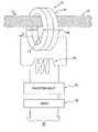
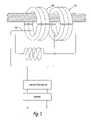
- FIG. 1 ashows a structure of an embodiment of the invention in which a single secondary winding functions as a bi-directional signal winding and a flux-canceling shorted winding.
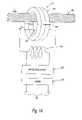
- FIG. 1 bshows a further embodiment that adds a low frequency magnetic core.
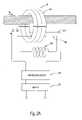
- FIGS. 2 a and 2 bshow alternative embodiments with a tertiary winding.
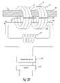
- FIG. 3shows another embodiment with a tertiary winding.
- FIGS. 4 a – 4 cshow schematic diagrams of the structures shown in FIGS. 13 .
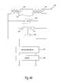
- FIG. 5shows a further embodiment of the invention that senses current in the power line.
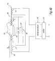
- FIG. 6shows another embodiment of the invention for sensing power line current.
- the magnitude of primary power line current that can be accommodated before an onset of significant core saturationcan be greatly increased by providing a secondary winding in which flows power frequency current in a direction opposite to the primary power line current.
- a currentis induced, of magnitude nearly equal to that of the primary current.
- a magnetomotive force driving a core, through which the primary and secondary windings are routedwill be reduced to an algebraic sum of respective current-times-number-of-turns in the primary and secondary windings, and be much lower than the primary current alone. This permits an increase of allowable primary current, before saturation begins.
- the conditions needed to induce substantial current in the secondary windinginclude limiting impedance in the shorted winding circuit to be much less than a magnetization inductance of the transformer comprising the primary and secondary windings and their common magnetic core.
- a radio frequency (rf) chokemust be connected in series with this shorted winding to avoid short circuiting the high frequency signal induced from the primary winding.
- the rf chokecarrying power frequency current almost as great as the primary current, must not saturate at the highest rated current.
- Such an rf choke coilmay be wound on a non-magnetic core or optionally include a magnetic core shaped to include a large non-magnetic component in its flux path.
- FIG. 1 ashows the structure of one embodiment of an inductive coupler, generally represented by the numeral 10 , in which a single secondary winding functions as a bi-directional signal winding and a flux-canceling shorted winding.
- Inductive coupler 10includes cores 105 , a secondary 115 and a choke coil 135 .
- a power line 100 of a power distribution systemis routed through cores 105 as a primary winding.
- Cores 105which are high frequency cores, are configured so that they may be placed around power line 100 while power line 100 is energized.
- cores 105may be horseshoe-shaped, or they may be split toroid cores to facilitate placing coupler 10 over power line 100 .
- Opposing pole faces where opposing split cores meetmay be in contact with each other.
- a gap 140 of nonmagnetic materialmay be introduced between them, commonly termed an air gap.
- Core 105is a magnetic core having a high magnetic permeability at a data communication frequency.
- Secondary 115is electrically insulated and passes through cores 105 , and connects to a communication device, e.g., a modem 120 , via an impedance matching and surge protection circuit 125 .
- a communication devicee.g., a modem 120
- an impedance matching and surge protection circuit 125serves as a data signaling circuit for coupling a data signal between power line 100 and modem 120 .
- Modem 120is further coupled for bi-directional data communication with a communication system (not shown) via data terminals 130 .
- Choke coil 135is a high frequency choke inductor connected across secondary 115 to present a low impedance for power frequency current and a high impedance for data communication frequency currents. Choke coil 135 is also part of a flux-canceling circuit for creating a flux-canceling power frequency current opposite in direction and comparable in magnitude to a power frequency current.
- the impedance of coil 135should be small in comparison with the magnetization impedance of secondary 115 , so as to increase the ratio of secondary current to primary power line current.
- the magnitude of the flux-canceling currentmay exceed one third of the power line current, preferably approaching equality to the power line current.
- a power frequency current I pflows in power line 100 , and induces a current I S in secondary 115 that flows in the opposite direction from I p .
- cores 105are subjected to a magnetomotive force of I p -I S , which is considerably less than I p alone. I p may thus be increased before cores 105 reach significant saturation.
- FIG. 1 bshows an embodiment in which one or more low-frequency, high-permeability cores 110 can be placed next to the high-frequency cores 105 of coupler 10 , taking care to ensure that high frequency eddy current losses are minimized in the added cores 110 .
- Typical low frequency magnetic core materialsincrease the power frequency impedances while having little effect on the radio frequency impedance.
- Cores 110increase the magnetization impedance of secondary 115 for power frequencies while not significantly affecting its impedance at signal frequencies.
- one or more cores 110are placed alongside cores 105 .
- Cores 110are magnetic cores having a permeability of thousands at the power frequency and nearly unity at the signal frequency.
- Secondary 115and is connected in series with choke coil 135 .
- Cores 110reduce a ratio of the power frequency impedance of choke coil 135 to the power frequency impedance of secondary 115 as compared to a ratio that would exist for the embodiment shown in FIG. 1 a .
- This ratio reductionincreases a ratio of secondary power frequency current to the primary power frequency current, and thus increases flux cancellation and the level of primary current that can be accommodated without encountering saturation in the high frequency cores 105 .
- Air gaps 150 and 155may be used in either or both cores 110 and 105 , respectively.
- secondary 115may have more than one turn around cores 105 and/or cores 110 , but all of the flux cancellation effects described above still pertain.
- FIG. 1 balso shows choke coil 135 configured with multiple turns with a connection of a center tap 137 of choke coil 135 to electrical ground 140 .
- Thisis a safety connection that provides a path for any fault current, should there be a breakdown of insulation between power line 100 and secondary 115 .
- Ground 140is typically a grounding rod at the base of the electric pole (not shown) nearest coupler 10 .
- a wire running up the electric pole from the grounding rodis also connected to any neutral wires present at that pole.
- Connecting ground 140 to center tap 137provides a symmetrical path for any high frequency noise that may be present on ground 140 to each of two modem terminals 121 and 122 , and cancellation of the noise by the factor of the common mode rejection ratio of modem 120 .
- FIG. 2 ashows the structure of an alternative implementation intended to increase the maximum level of power line current while maintaining data coupler functionality.
- a separate windinga tertiary winding, is used to induce a power frequency current in the opposite direction from that flowing in the power wire. It includes a choke acting as a low impedance at power frequency and a high impedance at signal frequency, which prevents the tertiary winding from acting as a shorted winding and thus short-circuiting the signal.
- Power line 100can be considered as a one-turn winding passing through core 105 .
- a secondary winding 210functions only as a signal frequency winding and connects to modem 120 via impedance matching and surge protection circuit 125 .
- tertiary winding 200is added, dedicated to inducing current so as to cancel a significant portion of the flux in core 105 .
- Tertiary winding 200is terminated by a high current, signal frequency choke 205 , similar to choke coil 135 in FIGS. 1 a and 1 b , which forms a short circuit for power frequency but not for signal frequency.
- FIG. 2 bshows the addition of a second magnetic core 110 to core 105 .
- Magnetic core 110has a high magnetic permeability at a power frequency. This increases the magnetization impedance of tertiary winding 200 so as to increase the ratio of tertiary current to primary power line current.
- FIG. 3shows the structure of another alternative implementation, which differs from that of FIG. 2 b in that a winding 300 passes through high frequency core 105 only, but not through power frequency core 110 .
- FIGS. 4 a , 4 b , and 4 care schematic diagrams corresponding to the structures in FIGS. 1 b , 2 b and- 3 respectively, and add an optional spark gap or gas tube surge arrestor 440 .
- Spark gap or surge arrestor 440absorbs energy that may be induced from power line 100 by lightning or other electrical surge conditions.
- Items 105 , 110 , 120 , 125 , 135 , 137 and 140are schematic representations of corresponding items in FIG. 1 b.
- ean “efficiency factor” that may approach unity
- I pthe primary current
- Mis the number of turns in tertiary winding 200 .
- the power frequency current in winding 210can be neglected, as the impedance matching and surge protection circuit 125 is designed with sufficient resistance as to reduce the circulation current to below one ampere (for example see provisional patent application No. 60/364,321, filed Mar. 14, 2002).
- Factor ewill approach 1 if cores 105 and 110 provide near-unity coupling coefficient, and the ratio of the impedance of signal frequency choke 205 to the magnetization impedance of tertiary
- tertiary winding 200may be constructed of a few turns, to allow use of smaller, more flexible wires, as the resultant magnetomotive force cancellation is a product of the current in tertiary winding 200 and the number of turns.
- the secondary currentis inversely related to the primary current by the turns ratio, but the product of the current multiplied by the number of turns remains constant.
- a secondary 450is dedicated to signal coupling and does not pass through the additional power frequency high permeability core 110 , reducing the coupling of low frequency noise into the signal circuit represented by impedance matching circuit 125 and modem 120 , and reducing eddy current losses.
- Spark gap or gas tube arrestor 440can be built into choke 205 or in close proximity and protect against these events.
- the flux-canceling secondary circuitcomprising secondary 115 and choke coil 135 in FIG. 1 a , in a power line coupler 10 can be extended for additional useful functionality, namely the measurement of the magnitude of the primary current flowing in the power wire.
- a power frequency currentflows through choke coil 135 at a magnitude roughly proportional to the power line current, while itself being insulated from primary potentials.
- this arrangementcan sense and monitor current in the primary winding, that is, the main power line.
- FIG. 5is a diagram showing an embodiment directed at such power line current sensing, and takes FIGS. 1 b and 4 a as its starting point.
- This systemincludes (a) a first current transformer through whose cores 105 and 110 power line 100 passes as a primary winding, and a secondary winding 115 , terminated by a choke coil 135 , such that current in secondary 115 is opposite in direction and proportional in magnitude to power current in power line 100 , and (b) a second current transformer 535 having a portion of choke coil 135 or one of its leads as a primary winding and developing in a secondary winding circuit a current sensing signal proportional to the secondary current and thus to the power current.
- modem 120connects to a communication system (not shown), and thus the output of current sensing transformer 535 may be conveniently connected to an interface device, e.g., signal acquisition device 555 , that converts a sensed current signal from current sensing transformer 535 to a digital value and sends the digital value to a power utility's monitoring location.
- an interface devicee.g., signal acquisition device 555
- FIG. 5shows power line 100 passing through cores 105 and 110 .
- Secondary 115 and choke coil 135form a secondary circuit.
- Choke coil 135shown split into two halves, includes a center tap point 520 connected via a conductor 525 to neutral or ground 530 .
- Current sensing transformer 535is clamped around a conductor at some point on the secondary circuit.
- the output of current sensing transformer 535I sense , is connected to signal acquisition device 555 , which in turn is connected via wires 565 to communications equipment (not shown).
- the current sensing indicationis thus conveniently transportable over the same communications system that modem 120 serves.
- I senseis proportional to choke coil current I choke .
- I Sis proportional to power line current I P , thus I sense is proportional to I p .
- the ratio between the magnitude I p flowing in power line 100 and current sensing current I sense reaching signal acquisition device 555is used in calibrating the signal acquisition device 555 .
- the ratio of I sense /I pmay be measured over a range of power frequency current I p , and a hardware or software proportionality compensating mechanism may be added to offset changes in the ratio.
- Current sensing transformer 535is preferably placed proximal to the point of attachment of center tap point 520 to conductor 525 . This reduces the effect of stray capacitance to ground on a high frequency circuit of which choke coil 135 is a part.
- FIG. 6shows an alternative arrangement that uses a current sensing coil rather than having current sensing transformer 535 placed around a conductor of choke coil 135 as in the embodiment of FIG. 5 .
- Current sensing coil 600is located coaxially with choke coil 135 , and can be considered a secondary of a transformer formed by choke coil 135 and current sensing coil 600 . This relationship holds whether choke coil 135 and/or sensing coil 600 have a nonmagnetic or magnetic core.
- the power frequency component of I sense induced in current sensing coil 600is fed to current measuring circuit 555 , which communicates with current monitoring equipment (not shown) as part of an electrical utility distribution grid (not shown).
- Current I senseis proportional to choke coil current I choke due to transformer induction between choke 135 and sensing coil 600 .
- I Sis proportional to power line current I p , thus I sense is proportional to I p .
- the resulting device including coupler 10 and current sensing coil 600represents a current transformer that may be placed around energized lines without disrupting service to power customers.
- Sensing coil 600is near coil 135 , which has high frequency signal current flowing through it and high frequency voltages across its terminals and with respect to ground.
- Rf chokes 615are connected in series with the terminals of sensing coil 600 so as to block any flow of high frequency current, and capacitor 620 , which short circuits any residual high frequency voltage and prevents its connection to current measuring circuit 555 .
- Capacitor 621may also be added to bypass any common mode high frequency current to ground.
Landscapes
- Engineering & Computer Science (AREA)
- Signal Processing (AREA)
- Power Engineering (AREA)
- Computer Networks & Wireless Communication (AREA)
- Microelectronics & Electronic Packaging (AREA)
- Cable Transmission Systems, Equalization Of Radio And Reduction Of Echo (AREA)
Abstract
Description
The present application is claiming priority of (a) U.S. Provisional Patent Application Ser. No. 60/376,377, filed on Apr. 29, 2002, and (b) U.S. Provisional Patent Application Ser. No. 60/416,603, filed on Oct. 7, 2002.
1. Field of the Invention
The invention generally relates to power line communications, and more particularly, to avoiding magnetic saturation in a power line inductive coupler.
2. Description of the Related Art
In a power line communication system, power frequency is typically in a range of 50–60 Hertz and a data communication signal frequency is typically in a range of 1–50 MHz. An inductive coupler for coupling modulated data onto and off of power lines includes a magnetic core through which pass the power line and a secondary winding. This is described, for example, in patent application Ser. No. 09/752,705, filed Dec. 28, 2000, patent application Ser. No. 10/082,063, filed Feb. 25, 2002, and provisional patent application No. 60/364,321, filed Mar. 14, 2002, which are incorporated herein by reference. One limitation to the usage of such couplers on high current primary and secondary wires is the limited ability of the magnetic cores to withstand large magnetization currents without magnetic saturation.
Saturation degrades performance in two ways. First, saturation reduces the magnetization inductance, which increases the shunt admittance loading on the data signal. Second, the instantaneous magnitude of power line current rises from zero to a peak value twice each cycle on ac power lines, and the data signal is amplitude modulated at twice the power line frequency and harmonics of this double frequency. So if the modulation depth exceeds some particular value, this modulation causes data errors.
One way to minimize core saturation is to introduce one or more air gaps in the magnetic circuit of the core, thus increasing magnetic resistance and permitting higher currents to flow before saturation is encountered. But the inductances of the primary and secondary windings fall in proportion to the total magnetic resistance, so a wide air gap would imply an impracticably large mass of core would be needed to have a minimum acceptable magnetization inductance. Increasing the number of turns is also impractical, because the coupler is usually installed on large diameter power lines without interrupting the power circuit.
A representative embodiment of the present invention includes a power line data coupler that couples a high frequency data signal between a power distribution system and a modem device. A high-frequency magnetic core has a high magnetic permeability at data communications frequencies. A data signaling secondary circuit couples a data signal between a power line primary winding of a power distribution system and a communications modem device. An inductive data coupler may be viewed as a transformer, with a power wire passing through coupler core acting as a primary winding and a coupler winding acting as a secondary. By terminating the secondary with a low value of power frequency impedance, such as a choke coil, primary current induces secondary current opposite in direction and comparable in magnitude to primary power frequency current. As a secondary current is induced in the opposite direction from the primary current, this secondary current cancels some of the power frequency flux induced in the coupler cores.
In one embodiment, the flux-canceling secondary circuit is short-circuited at power frequencies, using a choke inductor having a relatively low impedance at power frequencies and a relatively high impedance at data communication frequencies. Such a secondary circuit may also include a spark gap or gas tube surge arrestor connected in parallel with the choke inductor. The flux-canceling secondary circuit may be designed to have a total impedance much lower than half the magnetization reactance of the transformer secondary winding. The lower the impedance connected to the secondary, the closer the magnitude of the secondary current will approach the magnitude of the power line current.
The data signaling secondary winding may be wound over the high frequency magnetic core. The secondary winding of the flux-canceling secondary circuit may have multiple turns. It also may be connected to electrical ground, for example, by a center tap.
In another embodiment, an additional low-frequency magnetic core that has a high magnetic permeability at power line power frequencies may be used in conjunction with the high frequency core. The data signaling secondary winding may be wound over the high frequency magnetic core, but not over the low frequency magnetic core. The low frequency magnetic core may be selected to saturate at a maximum power line current level. Such saturation may limit the maximum power frequency current that may be induced in the secondary winding, and prevent its overheating.
A further embodiment of the present invention also includes a system for sensing current on a power distribution system power line. A first current transformer has a power distribution system power line as its primary winding and a coupler secondary coil as its secondary winding. Current in the coupler secondary coil is opposite in direction and proportional to power current in the power line. A second current transformer has the choke coil which is connected to the secondary winding as its primary winding and develops in its secondary winding circuit a current sensing signal proportional to the power current.
In yet a further embodiment, the flux-canceling coil is connected to electrical ground so that in case of insulation failure of the secondary winding, any fault current is shunted directly to ground. The second current transformer may then be located proximal to the ground connection. A signal acquisition device may be included for converting the current sensing signal to a representative digital value. The representative digital value may be provided to a computer network. A proportionality compensating mechanism may also be included for maintaining a relatively constant ratio between the current sensing signal and the power current as magnitude of the power current changes.
In another embodiment, the second current transformer may be replaced by a coil whose winding is coaxial with the choke coil. The coil thus acts as a power frequency current sensor.
The invention will be better understood by reference to the following detailed description and the accompanying drawings, in which:
The magnitude of primary power line current that can be accommodated before an onset of significant core saturation can be greatly increased by providing a secondary winding in which flows power frequency current in a direction opposite to the primary power line current. In a secondary winding whose terminals are connected to each other via a short circuit or very low impedance, a current is induced, of magnitude nearly equal to that of the primary current. Under these conditions, a magnetomotive force driving a core, through which the primary and secondary windings are routed, will be reduced to an algebraic sum of respective current-times-number-of-turns in the primary and secondary windings, and be much lower than the primary current alone. This permits an increase of allowable primary current, before saturation begins.
The conditions needed to induce substantial current in the secondary winding include limiting impedance in the shorted winding circuit to be much less than a magnetization inductance of the transformer comprising the primary and secondary windings and their common magnetic core. However, for a high frequency powerline coupler, a radio frequency (rf) choke must be connected in series with this shorted winding to avoid short circuiting the high frequency signal induced from the primary winding. The rf choke, carrying power frequency current almost as great as the primary current, must not saturate at the highest rated current. Such an rf choke coil may be wound on a non-magnetic core or optionally include a magnetic core shaped to include a large non-magnetic component in its flux path.
Secondary115 is electrically insulated and passes throughcores 105, and connects to a communication device, e.g., amodem 120, via an impedance matching andsurge protection circuit 125. Thus, secondary115 serves as a data signaling circuit for coupling a data signal betweenpower line 100 andmodem 120.Modem 120 is further coupled for bi-directional data communication with a communication system (not shown) viadata terminals 130.
In operation, a power frequency current Ipflows inpower line 100, and induces a current ISin secondary115 that flows in the opposite direction from Ip. With directions of Ipand ISas shown inFIG. 1 a,cores 105 are subjected to a magnetomotive force of Ip-IS, which is considerably less than Ipalone. Ipmay thus be increased beforecores 105 reach significant saturation.
Conflicting demands of minimal signal loading of the secondary circuit by means of a high impedance radio frequency choke and minimizing power frequency impedance by limiting choke impedance, can be overcome as follows.
In an alternative embodiment, secondary115 may have more than one turn aroundcores 105 and/orcores 110, but all of the flux cancellation effects described above still pertain.
Referring toFIG. 4 b, quantitatively, a power current Ipflows throughpower line 100, which serves as a primary winding220, inducing in tertiary winding200 an oppositely directed current It=eIp/M, where e is an “efficiency factor” that may approach unity, Ipis the primary current, and M is the number of turns in tertiary winding200. When e=1, the flux incores surge protection circuit 125 is designed with sufficient resistance as to reduce the circulation current to below one ampere (for example see provisional patent application No. 60/364,321, filed Mar. 14, 2002). Factor e will approach 1 ifcores signal frequency choke 205 to the magnetization impedance of tertiary winding200 is much less than unity at power frequency.
Embodiments of the invention are useful even if e deviates from unity because the magnetomotive force inhigh frequency core 105 is still reduced by a factor of 1−e. For example, for I=1000 amperes and e=0.9, the magnetomotive force in the high frequency core(s)105 is reduced to100 ampere-turns, manageable with currently available materials and a modest air gap.
For currents in the range of several hundred amperes and above, tertiary winding200 may be constructed of a few turns, to allow use of smaller, more flexible wires, as the resultant magnetomotive force cancellation is a product of the current in tertiary winding200 and the number of turns. As in a current transformer, the secondary current is inversely related to the primary current by the turns ratio, but the product of the current multiplied by the number of turns remains constant.
If the power line current exceeded a design current ofcoupler 10, excessive current might flow in secondary115 and overheat or melt the insulation of secondary115 or chokecoil 135. One way to avoid such damage is to select a power frequency core material that reaches saturation at the maximum rated current of conductor for secondary115 and chokecoil 135, thus limiting the induced current in the power frequency secondary.
For embodiments having separate secondaries for signal and flux-cancellation, as shown inFIGS. 3 and 4 c, a secondary450 is dedicated to signal coupling and does not pass through the additional power frequencyhigh permeability core 110, reducing the coupling of low frequency noise into the signal circuit represented byimpedance matching circuit 125 andmodem 120, and reducing eddy current losses.
Current surges due to lightning, switching transients, etc., that have a high slew rate, might induce large voltages inchoke 205 and might produce insulation breakdowns destructive to insulation. Spark gap orgas tube arrestor 440 can be built intochoke 205 or in close proximity and protect against these events.
The flux-canceling secondary circuit, comprising secondary115 and chokecoil 135 inFIG. 1 a, in apower line coupler 10 can be extended for additional useful functionality, namely the measurement of the magnitude of the primary current flowing in the power wire. When such an inductive coupler is installed on a power line, a power frequency current flows throughchoke coil 135 at a magnitude roughly proportional to the power line current, while itself being insulated from primary potentials. Thus, this arrangement can sense and monitor current in the primary winding, that is, the main power line.
This system includes (a) a first current transformer through whosecores power line 100 passes as a primary winding, and a secondary winding115, terminated by achoke coil 135, such that current in secondary115 is opposite in direction and proportional in magnitude to power current inpower line 100, and (b) a secondcurrent transformer 535 having a portion ofchoke coil 135 or one of its leads as a primary winding and developing in a secondary winding circuit a current sensing signal proportional to the secondary current and thus to the power current.
Sincechoke coil 135 is grounded, only minimal insulation is required for such a current sensing arrangement, and cost may be kept very low. Also,modem 120 connects to a communication system (not shown), and thus the output ofcurrent sensing transformer 535 may be conveniently connected to an interface device, e.g.,signal acquisition device 555, that converts a sensed current signal fromcurrent sensing transformer 535 to a digital value and sends the digital value to a power utility's monitoring location.
Current Isenseis proportional to choke coil current Ichoke. High pass components in matchingnetwork 125 block the flow of power frequency current, so Ichoke=ISat power frequency. ISis proportional to power line current IP, thus Isenseis proportional to Ip. The ratio between the magnitude Ipflowing inpower line 100 and current sensing current Isensereachingsignal acquisition device 555 is used in calibrating thesignal acquisition device 555.
As power frequency current Ipincreases, the saturation ofcores 105 and/or110 becomes significant, and the ratio of Isense/Ipdecreases, thus reducing the accuracy of measurement of Ip. To compensate for such saturation, the ratio of Isense/Ipmay be measured over a range of power frequency current Ip, and a hardware or software proportionality compensating mechanism may be added to offset changes in the ratio.
The power frequency component of Isenseinduced incurrent sensing coil 600 is fed tocurrent measuring circuit 555, which communicates with current monitoring equipment (not shown) as part of an electrical utility distribution grid (not shown). Current Isenseis proportional to choke coil current Ichokedue to transformer induction betweenchoke 135 andsensing coil 600. ISis proportional to power line current Ip, thus Isenseis proportional to Ip. The resultingdevice including coupler 10 andcurrent sensing coil 600 represents a current transformer that may be placed around energized lines without disrupting service to power customers.
Although various exemplary embodiments of the invention have been disclosed, it should be apparent to those skilled in the art that various changes and modifications can be made that will achieve some of the advantages of the invention without departing from the true scope of the invention. The present invention is intended to embrace all such changes and modifications that fall within the scope of the appended claims.
Claims (25)
1. A power line data coupler, comprising:
a magnetic core having a high magnetic permeability at a data communication frequency and being configured to allow a power line of a power distribution system to be routed through said magnetic core to serve as a primary winding;
a data signaling circuit that provides a secondary winding through said magnetic core for coupling a data signal between said power line and a communication device; and
a choke coil coupled to said data signaling circuit, across said secondary winding, for creating a flux-canceling power frequency current opposite in direction and comparable in magnitude to a power frequency current.
2. The coupler ofclaim 1 ,
wherein said magnetic core is a first magnetic core, and
wherein said coupler further comprises a second magnetic core having a high magnetic permeability at a power frequency and being configured to allow said power line and said secondary winding to be routed through said second magnetic core so as to increase power frequency impedance of said secondary winding.
3. The coupler ofclaim 2 , wherein said data signaling circuit secondary winding is wound around said first magnetic core, but not wound over said second magnetic core.
4. The coupler ofclaim 2 , wherein said second magnetic core saturates at a maximum power line current level.
5. The coupler ofclaim 1 , wherein said choke coil has a low impedance at said power frequency and a high impedance at said data communication frequency.
6. The coupler ofclaim 5 , further comprising a device connected in parallel with said choke coil for absorbing energy from an electrical surge.
7. The coupler ofclaim 1 ,wherein said choke coil has a total impedance much lower than half of a magnetization reactance of said secondary winding.
8. The coupler ofclaim 1 , wherein said choke coil is connected to an electrical ground.
9. The coupler ofclaim 1 , wherein said choke coil has a center tap connected to an electrical ground.
10. The coupler ofclaim 1 , wherein said secondary winding has multiple turns about said core.
11. The coupler ofclaim 10 , further comprising a current sensing transformer that employs said choke coil as a primary winding for developing a current sensing signal proportional to said power frequency current.
12. The coupler ofclaim 11 , wherein said current sensing signal is communicated to said communication device.
13. The coupler ofclaim 11 , wherein said current sensing transformer includes a magnetic core having an air gap.
14. The coupler ofclaim 11 , further comprising a proportionality compensating mechanism for maintaining a relatively constant ratio between said current sensing signal and said power frequency current as magnitude of said power frequency current changes.
15. The coupler ofclaim 1 , wherein said magnetic core includes an air gap.
16. A power line data coupler, comprising:
a magnetic core having a high magnetic permeability at a data communication frequency and being configured to allow a power line of a power distribution system to be routed through said magnetic core to serve as a primary winding;
a data signaling circuit that provides a secondary winding through said magnetic core for coupling a data signal between said power line and a communication device; and
a flux-canceling circuit that includes a tertiary winding through said magnetic core and a choke coil across said tertiary winding, for creating a flux-canceling power frequency current opposite in direction and comparable in magnitude to a power frequency current.
17. The coupler ofclaim 16 ,
wherein said magnetic core is a first magnetic core, and
wherein said coupler further comprises a second magnetic core having a high magnetic permeability at a power frequency and being configured to allow said power line and said tertiary winding to be routed through said second magnetic core, so as to increase power frequency impedance of said tertiary winding.
18. The coupler ofclaim 17 , wherein said secondary winding is not wound over said second magnetic core.
19. The coupler ofclaim 17 , wherein said secondary winding is wound over said second magnetic core.
20. A system of sensing current on a power distribution system power line, the system comprising:
a first current transformer that utilizes a power line of a power distribution system as a primary winding and a secondary winding connected to a choke coil, such that current in said choke coil is proportional to power current in said power line; and
a second current transformer having a conductor of said choke coil as a primary winding and developing in a secondary winding circuit a current sensing signal proportional to said power current.
21. The system ofclaim 20 , wherein said choke coil is connected to an electrical ground.
22. The system ofclaim 21 , wherein said second current transformer is located proximal to a point where said choke coil is connected to said electrical ground.
23. The system ofclaim 20 , further comprising a signal acquisition device for converting said current sensing signal to a digital value.
24. The system ofclaim 23 , wherein said digital value is provided to a computer network.
25. The system ofclaim 20 , further comprising a proportionality compensating mechanism for maintaining a relatively constant ratio between said current sensing signal and said power current as magnitude of said power current changes.
Priority Applications (1)
| Application Number | Priority Date | Filing Date | Title |
|---|---|---|---|
| US10/425,816US7061370B2 (en) | 2002-04-29 | 2003-04-29 | High current inductive coupler and current transformer for power lines |
Applications Claiming Priority (3)
| Application Number | Priority Date | Filing Date | Title |
|---|---|---|---|
| US37637702P | 2002-04-29 | 2002-04-29 | |
| US41660302P | 2002-10-07 | 2002-10-07 | |
| US10/425,816US7061370B2 (en) | 2002-04-29 | 2003-04-29 | High current inductive coupler and current transformer for power lines |
Publications (2)
| Publication Number | Publication Date |
|---|---|
| US20030201873A1 US20030201873A1 (en) | 2003-10-30 |
| US7061370B2true US7061370B2 (en) | 2006-06-13 |
Family
ID=29406751
Family Applications (1)
| Application Number | Title | Priority Date | Filing Date |
|---|---|---|---|
| US10/425,816Expired - LifetimeUS7061370B2 (en) | 2002-04-29 | 2003-04-29 | High current inductive coupler and current transformer for power lines |
Country Status (12)
| Country | Link |
|---|---|
| US (1) | US7061370B2 (en) |
| EP (1) | EP1500255A4 (en) |
| JP (1) | JP2005524248A (en) |
| KR (1) | KR20050007339A (en) |
| CN (1) | CN1650608A (en) |
| AU (1) | AU2003228733A1 (en) |
| BR (1) | BR0309616A (en) |
| CA (1) | CA2481579A1 (en) |
| EA (1) | EA006283B1 (en) |
| IL (1) | IL164706A0 (en) |
| MX (1) | MXPA04010598A (en) |
| WO (1) | WO2003094364A2 (en) |
Cited By (174)
| Publication number | Priority date | Publication date | Assignee | Title |
|---|---|---|---|---|
| US20040056734A1 (en)* | 2001-05-18 | 2004-03-25 | Davidow Clifford A. | Medium voltage signal coupling structure for last leg power grid high-speed data network |
| US20050169056A1 (en)* | 2002-12-10 | 2005-08-04 | Berkman William H. | Power line communications device and method |
| US20050275495A1 (en)* | 2002-06-21 | 2005-12-15 | Pridmore Charles F Jr | Power line coupling device and method of using the same |
| US20060125609A1 (en)* | 2000-08-09 | 2006-06-15 | Kline Paul A | Power line coupling device and method of using the same |
| US20060145834A1 (en)* | 2000-04-14 | 2006-07-06 | Berkman William H | Automated meter reading power line communication system and method |
| US20060176637A1 (en)* | 2004-03-15 | 2006-08-10 | Toru Kimura | High-frequency bypass unit |
| US20060244571A1 (en)* | 2005-04-29 | 2006-11-02 | Yaney David S | Power line coupling device and method of use |
| US7224243B2 (en)* | 2002-06-24 | 2007-05-29 | Current Technologies, Llc | Power line coupling device and method of using the same |
| US7245201B1 (en) | 2000-08-09 | 2007-07-17 | Current Technologies, Llc | Power line coupling device and method of using the same |
| US20080007416A1 (en)* | 2006-07-07 | 2008-01-10 | Ambient Corporation | Sensing current flowing through a power line |
| US20080291850A1 (en)* | 2005-11-25 | 2008-11-27 | Johnson Controls Denmark Aps | Systems and Methods for Power Line Communication with Refrigeration Containers |
| US20080315971A1 (en)* | 2007-06-21 | 2008-12-25 | Radtke William O | Power Line Data Signal Attenuation Device and Method |
| US20090002094A1 (en)* | 2007-06-26 | 2009-01-01 | Radtke William O | Power Line Coupling Device and Method |
| US20090002137A1 (en)* | 2007-06-26 | 2009-01-01 | Radtke William O | Power Line Coupling Device and Method |
| US20090085726A1 (en)* | 2007-09-27 | 2009-04-02 | Radtke William O | Power Line Communications Coupling Device and Method |
| US20090240449A1 (en)* | 2007-12-20 | 2009-09-24 | Tollgrade Communications, Inc. | Power Distribution Monitoring System And Method |
| US20100067387A1 (en)* | 2008-09-12 | 2010-03-18 | Shuji Tsunoda | Network Capture Method Using a Transformer |
| US20100231056A1 (en)* | 2009-03-16 | 2010-09-16 | Harris Corporation, Corporation Of The State Of Delaware | Power line e-field coupler and associated systems and methods |
| US20120319699A1 (en)* | 2010-04-14 | 2012-12-20 | Mitsubishi Electric Corporation | Insulation deterioration diagnosis apparatus |
| US9544006B2 (en) | 2014-11-20 | 2017-01-10 | At&T Intellectual Property I, L.P. | Transmission device with mode division multiplexing and methods for use therewith |
| US9596001B2 (en) | 2014-10-21 | 2017-03-14 | At&T Intellectual Property I, L.P. | Apparatus for providing communication services and methods thereof |
| US9608740B2 (en) | 2015-07-15 | 2017-03-28 | At&T Intellectual Property I, L.P. | Method and apparatus for launching a wave mode that mitigates interference |
| US9608692B2 (en) | 2015-06-11 | 2017-03-28 | At&T Intellectual Property I, L.P. | Repeater and methods for use therewith |
| US9615269B2 (en) | 2014-10-02 | 2017-04-04 | At&T Intellectual Property I, L.P. | Method and apparatus that provides fault tolerance in a communication network |
| US9628116B2 (en) | 2015-07-14 | 2017-04-18 | At&T Intellectual Property I, L.P. | Apparatus and methods for transmitting wireless signals |
| US9627768B2 (en) | 2014-10-21 | 2017-04-18 | At&T Intellectual Property I, L.P. | Guided-wave transmission device with non-fundamental mode propagation and methods for use therewith |
| US9640850B2 (en) | 2015-06-25 | 2017-05-02 | At&T Intellectual Property I, L.P. | Methods and apparatus for inducing a non-fundamental wave mode on a transmission medium |
| US9654173B2 (en) | 2014-11-20 | 2017-05-16 | At&T Intellectual Property I, L.P. | Apparatus for powering a communication device and methods thereof |
| US9653770B2 (en) | 2014-10-21 | 2017-05-16 | At&T Intellectual Property I, L.P. | Guided wave coupler, coupling module and methods for use therewith |
| US9661505B2 (en) | 2013-11-06 | 2017-05-23 | At&T Intellectual Property I, L.P. | Surface-wave communications and methods thereof |
| US9667317B2 (en) | 2015-06-15 | 2017-05-30 | At&T Intellectual Property I, L.P. | Method and apparatus for providing security using network traffic adjustments |
| US9685992B2 (en) | 2014-10-03 | 2017-06-20 | At&T Intellectual Property I, L.P. | Circuit panel network and methods thereof |
| US9692101B2 (en) | 2014-08-26 | 2017-06-27 | At&T Intellectual Property I, L.P. | Guided wave couplers for coupling electromagnetic waves between a waveguide surface and a surface of a wire |
| US9699785B2 (en) | 2012-12-05 | 2017-07-04 | At&T Intellectual Property I, L.P. | Backhaul link for distributed antenna system |
| US9705561B2 (en) | 2015-04-24 | 2017-07-11 | At&T Intellectual Property I, L.P. | Directional coupling device and methods for use therewith |
| US9705610B2 (en) | 2014-10-21 | 2017-07-11 | At&T Intellectual Property I, L.P. | Transmission device with impairment compensation and methods for use therewith |
| US9712350B2 (en) | 2014-11-20 | 2017-07-18 | At&T Intellectual Property I, L.P. | Transmission device with channel equalization and control and methods for use therewith |
| US9722318B2 (en) | 2015-07-14 | 2017-08-01 | At&T Intellectual Property I, L.P. | Method and apparatus for coupling an antenna to a device |
| US9729197B2 (en) | 2015-10-01 | 2017-08-08 | At&T Intellectual Property I, L.P. | Method and apparatus for communicating network management traffic over a network |
| US9735833B2 (en) | 2015-07-31 | 2017-08-15 | At&T Intellectual Property I, L.P. | Method and apparatus for communications management in a neighborhood network |
| US9742462B2 (en) | 2014-12-04 | 2017-08-22 | At&T Intellectual Property I, L.P. | Transmission medium and communication interfaces and methods for use therewith |
| US9749013B2 (en) | 2015-03-17 | 2017-08-29 | At&T Intellectual Property I, L.P. | Method and apparatus for reducing attenuation of electromagnetic waves guided by a transmission medium |
| US9748626B2 (en) | 2015-05-14 | 2017-08-29 | At&T Intellectual Property I, L.P. | Plurality of cables having different cross-sectional shapes which are bundled together to form a transmission medium |
| US9749053B2 (en) | 2015-07-23 | 2017-08-29 | At&T Intellectual Property I, L.P. | Node device, repeater and methods for use therewith |
| US9762289B2 (en) | 2014-10-14 | 2017-09-12 | At&T Intellectual Property I, L.P. | Method and apparatus for transmitting or receiving signals in a transportation system |
| US9769020B2 (en) | 2014-10-21 | 2017-09-19 | At&T Intellectual Property I, L.P. | Method and apparatus for responding to events affecting communications in a communication network |
| US9768833B2 (en) | 2014-09-15 | 2017-09-19 | At&T Intellectual Property I, L.P. | Method and apparatus for sensing a condition in a transmission medium of electromagnetic waves |
| US9769128B2 (en) | 2015-09-28 | 2017-09-19 | At&T Intellectual Property I, L.P. | Method and apparatus for encryption of communications over a network |
| US9780834B2 (en) | 2014-10-21 | 2017-10-03 | At&T Intellectual Property I, L.P. | Method and apparatus for transmitting electromagnetic waves |
| US9787412B2 (en) | 2015-06-25 | 2017-10-10 | At&T Intellectual Property I, L.P. | Methods and apparatus for inducing a fundamental wave mode on a transmission medium |
| US9793951B2 (en) | 2015-07-15 | 2017-10-17 | At&T Intellectual Property I, L.P. | Method and apparatus for launching a wave mode that mitigates interference |
| US9794003B2 (en) | 2013-12-10 | 2017-10-17 | At&T Intellectual Property I, L.P. | Quasi-optical coupler |
| US9793954B2 (en) | 2015-04-28 | 2017-10-17 | At&T Intellectual Property I, L.P. | Magnetic coupling device and methods for use therewith |
| US9793955B2 (en) | 2015-04-24 | 2017-10-17 | At&T Intellectual Property I, Lp | Passive electrical coupling device and methods for use therewith |
| US9800327B2 (en) | 2014-11-20 | 2017-10-24 | At&T Intellectual Property I, L.P. | Apparatus for controlling operations of a communication device and methods thereof |
| US9820146B2 (en) | 2015-06-12 | 2017-11-14 | At&T Intellectual Property I, L.P. | Method and apparatus for authentication and identity management of communicating devices |
| US9838078B2 (en) | 2015-07-31 | 2017-12-05 | At&T Intellectual Property I, L.P. | Method and apparatus for exchanging communication signals |
| US9836957B2 (en) | 2015-07-14 | 2017-12-05 | At&T Intellectual Property I, L.P. | Method and apparatus for communicating with premises equipment |
| US9838896B1 (en) | 2016-12-09 | 2017-12-05 | At&T Intellectual Property I, L.P. | Method and apparatus for assessing network coverage |
| US9847850B2 (en) | 2014-10-14 | 2017-12-19 | At&T Intellectual Property I, L.P. | Method and apparatus for adjusting a mode of communication in a communication network |
| US9847566B2 (en) | 2015-07-14 | 2017-12-19 | At&T Intellectual Property I, L.P. | Method and apparatus for adjusting a field of a signal to mitigate interference |
| US9853342B2 (en) | 2015-07-14 | 2017-12-26 | At&T Intellectual Property I, L.P. | Dielectric transmission medium connector and methods for use therewith |
| US9860075B1 (en) | 2016-08-26 | 2018-01-02 | At&T Intellectual Property I, L.P. | Method and communication node for broadband distribution |
| US9866309B2 (en) | 2015-06-03 | 2018-01-09 | At&T Intellectual Property I, Lp | Host node device and methods for use therewith |
| US9866276B2 (en) | 2014-10-10 | 2018-01-09 | At&T Intellectual Property I, L.P. | Method and apparatus for arranging communication sessions in a communication system |
| US9865911B2 (en) | 2015-06-25 | 2018-01-09 | At&T Intellectual Property I, L.P. | Waveguide system for slot radiating first electromagnetic waves that are combined into a non-fundamental wave mode second electromagnetic wave on a transmission medium |
| US9871282B2 (en) | 2015-05-14 | 2018-01-16 | At&T Intellectual Property I, L.P. | At least one transmission medium having a dielectric surface that is covered at least in part by a second dielectric |
| US9871283B2 (en) | 2015-07-23 | 2018-01-16 | At&T Intellectual Property I, Lp | Transmission medium having a dielectric core comprised of plural members connected by a ball and socket configuration |
| US9871558B2 (en) | 2014-10-21 | 2018-01-16 | At&T Intellectual Property I, L.P. | Guided-wave transmission device and methods for use therewith |
| US9876571B2 (en) | 2015-02-20 | 2018-01-23 | At&T Intellectual Property I, Lp | Guided-wave transmission device with non-fundamental mode propagation and methods for use therewith |
| US9876264B2 (en) | 2015-10-02 | 2018-01-23 | At&T Intellectual Property I, Lp | Communication system, guided wave switch and methods for use therewith |
| US9876605B1 (en) | 2016-10-21 | 2018-01-23 | At&T Intellectual Property I, L.P. | Launcher and coupling system to support desired guided wave mode |
| US9882277B2 (en) | 2015-10-02 | 2018-01-30 | At&T Intellectual Property I, Lp | Communication device and antenna assembly with actuated gimbal mount |
| US9882257B2 (en) | 2015-07-14 | 2018-01-30 | At&T Intellectual Property I, L.P. | Method and apparatus for launching a wave mode that mitigates interference |
| US9887447B2 (en) | 2015-05-14 | 2018-02-06 | At&T Intellectual Property I, L.P. | Transmission medium having multiple cores and methods for use therewith |
| US9893795B1 (en) | 2016-12-07 | 2018-02-13 | At&T Intellectual Property I, Lp | Method and repeater for broadband distribution |
| US9904535B2 (en) | 2015-09-14 | 2018-02-27 | At&T Intellectual Property I, L.P. | Method and apparatus for distributing software |
| US9906269B2 (en) | 2014-09-17 | 2018-02-27 | At&T Intellectual Property I, L.P. | Monitoring and mitigating conditions in a communication network |
| US9911020B1 (en) | 2016-12-08 | 2018-03-06 | At&T Intellectual Property I, L.P. | Method and apparatus for tracking via a radio frequency identification device |
| US9913139B2 (en) | 2015-06-09 | 2018-03-06 | At&T Intellectual Property I, L.P. | Signal fingerprinting for authentication of communicating devices |
| US9912382B2 (en) | 2015-06-03 | 2018-03-06 | At&T Intellectual Property I, Lp | Network termination and methods for use therewith |
| US9912027B2 (en) | 2015-07-23 | 2018-03-06 | At&T Intellectual Property I, L.P. | Method and apparatus for exchanging communication signals |
| US9912419B1 (en) | 2016-08-24 | 2018-03-06 | At&T Intellectual Property I, L.P. | Method and apparatus for managing a fault in a distributed antenna system |
| US9917341B2 (en) | 2015-05-27 | 2018-03-13 | At&T Intellectual Property I, L.P. | Apparatus and method for launching electromagnetic waves and for modifying radial dimensions of the propagating electromagnetic waves |
| US9930668B2 (en) | 2013-05-31 | 2018-03-27 | At&T Intellectual Property I, L.P. | Remote distributed antenna system |
| US9927517B1 (en) | 2016-12-06 | 2018-03-27 | At&T Intellectual Property I, L.P. | Apparatus and methods for sensing rainfall |
| US9948333B2 (en) | 2015-07-23 | 2018-04-17 | At&T Intellectual Property I, L.P. | Method and apparatus for wireless communications to mitigate interference |
| US9948354B2 (en) | 2015-04-28 | 2018-04-17 | At&T Intellectual Property I, L.P. | Magnetic coupling device with reflective plate and methods for use therewith |
| US9954287B2 (en) | 2014-11-20 | 2018-04-24 | At&T Intellectual Property I, L.P. | Apparatus for converting wireless signals and electromagnetic waves and methods thereof |
| US9967173B2 (en) | 2015-07-31 | 2018-05-08 | At&T Intellectual Property I, L.P. | Method and apparatus for authentication and identity management of communicating devices |
| US9973940B1 (en) | 2017-02-27 | 2018-05-15 | At&T Intellectual Property I, L.P. | Apparatus and methods for dynamic impedance matching of a guided wave launcher |
| US9991580B2 (en) | 2016-10-21 | 2018-06-05 | At&T Intellectual Property I, L.P. | Launcher and coupling system for guided wave mode cancellation |
| US9997819B2 (en) | 2015-06-09 | 2018-06-12 | At&T Intellectual Property I, L.P. | Transmission medium and method for facilitating propagation of electromagnetic waves via a core |
| US9998870B1 (en) | 2016-12-08 | 2018-06-12 | At&T Intellectual Property I, L.P. | Method and apparatus for proximity sensing |
| US9999038B2 (en) | 2013-05-31 | 2018-06-12 | At&T Intellectual Property I, L.P. | Remote distributed antenna system |
| US10009063B2 (en) | 2015-09-16 | 2018-06-26 | At&T Intellectual Property I, L.P. | Method and apparatus for use with a radio distributed antenna system having an out-of-band reference signal |
| US10009067B2 (en) | 2014-12-04 | 2018-06-26 | At&T Intellectual Property I, L.P. | Method and apparatus for configuring a communication interface |
| US10009901B2 (en) | 2015-09-16 | 2018-06-26 | At&T Intellectual Property I, L.P. | Method, apparatus, and computer-readable storage medium for managing utilization of wireless resources between base stations |
| US10009065B2 (en) | 2012-12-05 | 2018-06-26 | At&T Intellectual Property I, L.P. | Backhaul link for distributed antenna system |
| US10020587B2 (en) | 2015-07-31 | 2018-07-10 | At&T Intellectual Property I, L.P. | Radial antenna and methods for use therewith |
| US10020844B2 (en) | 2016-12-06 | 2018-07-10 | T&T Intellectual Property I, L.P. | Method and apparatus for broadcast communication via guided waves |
| US10027397B2 (en) | 2016-12-07 | 2018-07-17 | At&T Intellectual Property I, L.P. | Distributed antenna system and methods for use therewith |
| US10033107B2 (en) | 2015-07-14 | 2018-07-24 | At&T Intellectual Property I, L.P. | Method and apparatus for coupling an antenna to a device |
| US10033108B2 (en) | 2015-07-14 | 2018-07-24 | At&T Intellectual Property I, L.P. | Apparatus and methods for generating an electromagnetic wave having a wave mode that mitigates interference |
| US10044409B2 (en) | 2015-07-14 | 2018-08-07 | At&T Intellectual Property I, L.P. | Transmission medium and methods for use therewith |
| US10069535B2 (en) | 2016-12-08 | 2018-09-04 | At&T Intellectual Property I, L.P. | Apparatus and methods for launching electromagnetic waves having a certain electric field structure |
| US10079661B2 (en) | 2015-09-16 | 2018-09-18 | At&T Intellectual Property I, L.P. | Method and apparatus for use with a radio distributed antenna system having a clock reference |
| US10090606B2 (en) | 2015-07-15 | 2018-10-02 | At&T Intellectual Property I, L.P. | Antenna system with dielectric array and methods for use therewith |
| US10090594B2 (en) | 2016-11-23 | 2018-10-02 | At&T Intellectual Property I, L.P. | Antenna system having structural configurations for assembly |
| US10103801B2 (en) | 2015-06-03 | 2018-10-16 | At&T Intellectual Property I, L.P. | Host node device and methods for use therewith |
| US10103422B2 (en) | 2016-12-08 | 2018-10-16 | At&T Intellectual Property I, L.P. | Method and apparatus for mounting network devices |
| US10135147B2 (en) | 2016-10-18 | 2018-11-20 | At&T Intellectual Property I, L.P. | Apparatus and methods for launching guided waves via an antenna |
| US10135146B2 (en) | 2016-10-18 | 2018-11-20 | At&T Intellectual Property I, L.P. | Apparatus and methods for launching guided waves via circuits |
| US10135145B2 (en) | 2016-12-06 | 2018-11-20 | At&T Intellectual Property I, L.P. | Apparatus and methods for generating an electromagnetic wave along a transmission medium |
| US10136434B2 (en) | 2015-09-16 | 2018-11-20 | At&T Intellectual Property I, L.P. | Method and apparatus for use with a radio distributed antenna system having an ultra-wideband control channel |
| US10142086B2 (en) | 2015-06-11 | 2018-11-27 | At&T Intellectual Property I, L.P. | Repeater and methods for use therewith |
| US10139820B2 (en) | 2016-12-07 | 2018-11-27 | At&T Intellectual Property I, L.P. | Method and apparatus for deploying equipment of a communication system |
| US10148016B2 (en) | 2015-07-14 | 2018-12-04 | At&T Intellectual Property I, L.P. | Apparatus and methods for communicating utilizing an antenna array |
| US10144036B2 (en) | 2015-01-30 | 2018-12-04 | At&T Intellectual Property I, L.P. | Method and apparatus for mitigating interference affecting a propagation of electromagnetic waves guided by a transmission medium |
| US10168695B2 (en) | 2016-12-07 | 2019-01-01 | At&T Intellectual Property I, L.P. | Method and apparatus for controlling an unmanned aircraft |
| US10170840B2 (en) | 2015-07-14 | 2019-01-01 | At&T Intellectual Property I, L.P. | Apparatus and methods for sending or receiving electromagnetic signals |
| US10178445B2 (en) | 2016-11-23 | 2019-01-08 | At&T Intellectual Property I, L.P. | Methods, devices, and systems for load balancing between a plurality of waveguides |
| US10205655B2 (en) | 2015-07-14 | 2019-02-12 | At&T Intellectual Property I, L.P. | Apparatus and methods for communicating utilizing an antenna array and multiple communication paths |
| US10225025B2 (en) | 2016-11-03 | 2019-03-05 | At&T Intellectual Property I, L.P. | Method and apparatus for detecting a fault in a communication system |
| US10224634B2 (en) | 2016-11-03 | 2019-03-05 | At&T Intellectual Property I, L.P. | Methods and apparatus for adjusting an operational characteristic of an antenna |
| US10243270B2 (en) | 2016-12-07 | 2019-03-26 | At&T Intellectual Property I, L.P. | Beam adaptive multi-feed dielectric antenna system and methods for use therewith |
| US10243784B2 (en) | 2014-11-20 | 2019-03-26 | At&T Intellectual Property I, L.P. | System for generating topology information and methods thereof |
| US10264586B2 (en) | 2016-12-09 | 2019-04-16 | At&T Mobility Ii Llc | Cloud-based packet controller and methods for use therewith |
| US10291334B2 (en) | 2016-11-03 | 2019-05-14 | At&T Intellectual Property I, L.P. | System for detecting a fault in a communication system |
| US10291311B2 (en) | 2016-09-09 | 2019-05-14 | At&T Intellectual Property I, L.P. | Method and apparatus for mitigating a fault in a distributed antenna system |
| US10298293B2 (en) | 2017-03-13 | 2019-05-21 | At&T Intellectual Property I, L.P. | Apparatus of communication utilizing wireless network devices |
| US10305190B2 (en) | 2016-12-01 | 2019-05-28 | At&T Intellectual Property I, L.P. | Reflecting dielectric antenna system and methods for use therewith |
| US10312567B2 (en) | 2016-10-26 | 2019-06-04 | At&T Intellectual Property I, L.P. | Launcher with planar strip antenna and methods for use therewith |
| US10320586B2 (en) | 2015-07-14 | 2019-06-11 | At&T Intellectual Property I, L.P. | Apparatus and methods for generating non-interfering electromagnetic waves on an insulated transmission medium |
| US10326494B2 (en) | 2016-12-06 | 2019-06-18 | At&T Intellectual Property I, L.P. | Apparatus for measurement de-embedding and methods for use therewith |
| US10326689B2 (en) | 2016-12-08 | 2019-06-18 | At&T Intellectual Property I, L.P. | Method and system for providing alternative communication paths |
| US10340601B2 (en) | 2016-11-23 | 2019-07-02 | At&T Intellectual Property I, L.P. | Multi-antenna system and methods for use therewith |
| US10340573B2 (en) | 2016-10-26 | 2019-07-02 | At&T Intellectual Property I, L.P. | Launcher with cylindrical coupling device and methods for use therewith |
| US10340603B2 (en) | 2016-11-23 | 2019-07-02 | At&T Intellectual Property I, L.P. | Antenna system having shielded structural configurations for assembly |
| US10340600B2 (en) | 2016-10-18 | 2019-07-02 | At&T Intellectual Property I, L.P. | Apparatus and methods for launching guided waves via plural waveguide systems |
| US10341142B2 (en) | 2015-07-14 | 2019-07-02 | At&T Intellectual Property I, L.P. | Apparatus and methods for generating non-interfering electromagnetic waves on an uninsulated conductor |
| US10340983B2 (en) | 2016-12-09 | 2019-07-02 | At&T Intellectual Property I, L.P. | Method and apparatus for surveying remote sites via guided wave communications |
| US10355367B2 (en) | 2015-10-16 | 2019-07-16 | At&T Intellectual Property I, L.P. | Antenna structure for exchanging wireless signals |
| US10359749B2 (en) | 2016-12-07 | 2019-07-23 | At&T Intellectual Property I, L.P. | Method and apparatus for utilities management via guided wave communication |
| US10361489B2 (en) | 2016-12-01 | 2019-07-23 | At&T Intellectual Property I, L.P. | Dielectric dish antenna system and methods for use therewith |
| US10374316B2 (en) | 2016-10-21 | 2019-08-06 | At&T Intellectual Property I, L.P. | System and dielectric antenna with non-uniform dielectric |
| US10382976B2 (en) | 2016-12-06 | 2019-08-13 | At&T Intellectual Property I, L.P. | Method and apparatus for managing wireless communications based on communication paths and network device positions |
| US10389029B2 (en) | 2016-12-07 | 2019-08-20 | At&T Intellectual Property I, L.P. | Multi-feed dielectric antenna system with core selection and methods for use therewith |
| US10389037B2 (en) | 2016-12-08 | 2019-08-20 | At&T Intellectual Property I, L.P. | Apparatus and methods for selecting sections of an antenna array and use therewith |
| US10411356B2 (en) | 2016-12-08 | 2019-09-10 | At&T Intellectual Property I, L.P. | Apparatus and methods for selectively targeting communication devices with an antenna array |
| US10439675B2 (en) | 2016-12-06 | 2019-10-08 | At&T Intellectual Property I, L.P. | Method and apparatus for repeating guided wave communication signals |
| US10446936B2 (en) | 2016-12-07 | 2019-10-15 | At&T Intellectual Property I, L.P. | Multi-feed dielectric antenna system and methods for use therewith |
| US10498044B2 (en) | 2016-11-03 | 2019-12-03 | At&T Intellectual Property I, L.P. | Apparatus for configuring a surface of an antenna |
| US10530505B2 (en) | 2016-12-08 | 2020-01-07 | At&T Intellectual Property I, L.P. | Apparatus and methods for launching electromagnetic waves along a transmission medium |
| US10535928B2 (en) | 2016-11-23 | 2020-01-14 | At&T Intellectual Property I, L.P. | Antenna system and methods for use therewith |
| US10547348B2 (en) | 2016-12-07 | 2020-01-28 | At&T Intellectual Property I, L.P. | Method and apparatus for switching transmission mediums in a communication system |
| US10601494B2 (en) | 2016-12-08 | 2020-03-24 | At&T Intellectual Property I, L.P. | Dual-band communication device and method for use therewith |
| US10607475B1 (en) | 2019-03-21 | 2020-03-31 | Underground Systems, Inc. | Remote monitoring system |
| US10637149B2 (en) | 2016-12-06 | 2020-04-28 | At&T Intellectual Property I, L.P. | Injection molded dielectric antenna and methods for use therewith |
| US10650940B2 (en) | 2015-05-15 | 2020-05-12 | At&T Intellectual Property I, L.P. | Transmission medium having a conductive material and methods for use therewith |
| US10665942B2 (en) | 2015-10-16 | 2020-05-26 | At&T Intellectual Property I, L.P. | Method and apparatus for adjusting wireless communications |
| US10694379B2 (en) | 2016-12-06 | 2020-06-23 | At&T Intellectual Property I, L.P. | Waveguide system with device-based authentication and methods for use therewith |
| US10727599B2 (en) | 2016-12-06 | 2020-07-28 | At&T Intellectual Property I, L.P. | Launcher with slot antenna and methods for use therewith |
| US10755542B2 (en) | 2016-12-06 | 2020-08-25 | At&T Intellectual Property I, L.P. | Method and apparatus for surveillance via guided wave communication |
| US10777873B2 (en) | 2016-12-08 | 2020-09-15 | At&T Intellectual Property I, L.P. | Method and apparatus for mounting network devices |
| US10784670B2 (en) | 2015-07-23 | 2020-09-22 | At&T Intellectual Property I, L.P. | Antenna support for aligning an antenna |
| US10797781B2 (en) | 2015-06-03 | 2020-10-06 | At&T Intellectual Property I, L.P. | Client node device and methods for use therewith |
| US10811767B2 (en) | 2016-10-21 | 2020-10-20 | At&T Intellectual Property I, L.P. | System and dielectric antenna with convex dielectric radome |
| US10819035B2 (en) | 2016-12-06 | 2020-10-27 | At&T Intellectual Property I, L.P. | Launcher with helical antenna and methods for use therewith |
| US10916969B2 (en) | 2016-12-08 | 2021-02-09 | At&T Intellectual Property I, L.P. | Method and apparatus for providing power using an inductive coupling |
| US10938108B2 (en) | 2016-12-08 | 2021-03-02 | At&T Intellectual Property I, L.P. | Frequency selective multi-feed dielectric antenna system and methods for use therewith |
| US11032819B2 (en) | 2016-09-15 | 2021-06-08 | At&T Intellectual Property I, L.P. | Method and apparatus for use with a radio distributed antenna system having a control channel reference signal |
| US12068105B2 (en) | 2019-09-30 | 2024-08-20 | Solaredge Technologies Ltd. | Magnetic flux cancellation for power line communications |
| US12438281B2 (en) | 2021-11-19 | 2025-10-07 | Sderotech, Inc. | Variable dielectric based antenna with improved response time |
Families Citing this family (42)
| Publication number | Priority date | Publication date | Assignee | Title |
|---|---|---|---|---|
| US7103240B2 (en) | 2001-02-14 | 2006-09-05 | Current Technologies, Llc | Method and apparatus for providing inductive coupling and decoupling of high-frequency, high-bandwidth data signals directly on and off of a high voltage power line |
| US6965303B2 (en) | 2002-12-10 | 2005-11-15 | Current Technologies, Llc | Power line communication system and method |
| US7075414B2 (en) | 2003-05-13 | 2006-07-11 | Current Technologies, Llc | Device and method for communicating data signals through multiple power line conductors |
| US7064654B2 (en) | 2002-12-10 | 2006-06-20 | Current Technologies, Llc | Power line communication system and method of operating the same |
| US6980091B2 (en) | 2002-12-10 | 2005-12-27 | Current Technologies, Llc | Power line communication system and method of operating the same |
| US7046124B2 (en) | 2003-01-21 | 2006-05-16 | Current Technologies, Llc | Power line coupling device and method of using the same |
| US7312694B2 (en) | 2003-03-14 | 2007-12-25 | Ameren Corporation | Capacitive couplers and methods for communicating data over an electrical power delivery system |
| DE10331316A1 (en)* | 2003-07-10 | 2005-02-10 | Siemens Ag | ferrite |
| US7852837B1 (en) | 2003-12-24 | 2010-12-14 | At&T Intellectual Property Ii, L.P. | Wi-Fi/BPL dual mode repeaters for power line networks |
| US7113134B1 (en) | 2004-03-12 | 2006-09-26 | Current Technologies, Llc | Transformer antenna device and method of using the same |
| ES2253066B2 (en)* | 2004-03-15 | 2007-03-16 | Electrotecnica Arteche Hermanos, S.A. | PROCEDURE AND DEVICE FOR REGULATION AND COMPENSATION OF HIGH FREQUENCY MAGNETIC FIELD IN THE MAGNETIC NUCLEUS OF A SIGNAL INDUCTIVE COUPLING. |
| US7091849B1 (en) | 2004-05-06 | 2006-08-15 | At&T Corp. | Inbound interference reduction in a broadband powerline system |
| US8462902B1 (en) | 2004-12-01 | 2013-06-11 | At&T Intellectual Property Ii, L.P. | Interference control in a broadband powerline communication system |
| US9172429B2 (en) | 2004-12-01 | 2015-10-27 | At&T Intellectual Property Ii, L.P. | Interference control in a broadband powerline communication system |
| US7148799B2 (en)* | 2004-12-14 | 2006-12-12 | Ambient Corporation | Arrangement of daisy chained inductive couplers for data communication |
| CN101449345A (en)* | 2005-05-20 | 2009-06-03 | 安比恩特公司 | Inductive coupler for power line communications, having a member that provides an intended path for a flashover to discharge to ground |
| US7535685B2 (en)* | 2006-01-31 | 2009-05-19 | Amperion, Inc. | Radio frequency signal coupler, coupling system and method |
| US20080106154A1 (en)* | 2006-11-07 | 2008-05-08 | Boyd Joseph J | Electromagnetic energy collector |
| JP4830846B2 (en)* | 2006-12-25 | 2011-12-07 | Tdk株式会社 | Signal coupling device |
| CN101072049B (en)* | 2007-06-19 | 2010-08-25 | 北京意科通信技术有限责任公司 | Metal pipeline data transmission coupler and its processing method |
| JP5335226B2 (en)* | 2007-11-30 | 2013-11-06 | 三重電子株式会社 | Movable transmission device |
| WO2010035264A1 (en)* | 2008-09-26 | 2010-04-01 | Xtend Networks Ltd. | Chockless power coupler |
| EP2534546A4 (en)* | 2010-02-09 | 2015-05-20 | Nelson Irrigation Corp | Inductively coupled distributed control system |
| FR2960722B1 (en)* | 2010-05-26 | 2013-03-08 | Sagem Defense Securite | POWER COUPLER / LOW FREQUENCY FLOW CANCELLATION DATA |
| JP5172938B2 (en)* | 2010-12-14 | 2013-03-27 | 本田技研工業株式会社 | Vehicle power line communication device |
| CA2868663C (en)* | 2013-10-21 | 2016-11-08 | Tomasz Barczyk | Methods and systems relating to ac current measurements |
| FR3047084B1 (en)* | 2016-01-22 | 2018-02-16 | Safran Electrical & Power | DEVICE FOR MEASURING THE CURRENT CURRENT AGAINST OVERVOLTAGES IN THE EVENT OF OPENING THE CIRCUIT |
| JP6952254B2 (en)* | 2016-06-03 | 2021-10-20 | パナソニックIpマネジメント株式会社 | Coupler for power line carrier communication |
| US10642321B2 (en) | 2017-01-25 | 2020-05-05 | Oracle International Corporation | Power distribution unit self-identification |
| US10615641B2 (en)* | 2017-06-26 | 2020-04-07 | Vutiliti, Inc. | Induction powered electricity current monitoring |
| WO2019051448A1 (en) | 2017-09-11 | 2019-03-14 | Antronix Inc. | Power passing directional coupler having a split ferrite element |
| WO2019070583A1 (en)* | 2017-10-02 | 2019-04-11 | ABB Schweiz AB | Flux absorber for power line device |
| US11181555B2 (en) | 2018-04-30 | 2021-11-23 | Isentek Inc. | Current sensing method and current sensor |
| CN109755009B (en)* | 2019-01-25 | 2020-12-08 | 南京师范大学 | A dual-magnetic-core single-winding line inductive energy-capturing device and its configuration method |
| US11639950B2 (en)* | 2020-03-06 | 2023-05-02 | Hioki E.E. Corporation | Current sensor |
| CN113552401A (en)* | 2021-07-07 | 2021-10-26 | 国电南瑞科技股份有限公司 | High-frequency current sensor adopting auxiliary winding degaussing and discharge current detection method |
| CN115495921B (en)* | 2022-09-29 | 2023-04-07 | 东南大学 | Power electronic system simulation method based on loop current method decoupling |
| CN115963443B (en)* | 2023-03-13 | 2023-06-16 | 国网江西省电力有限公司电力科学研究院 | All-fiber current transformer abnormality processing method and system |
| CN116660601B (en)* | 2023-07-17 | 2025-08-26 | 国网智能电网研究院有限公司 | A wide-band AC/DC magnetic sensor with a milliampere to hundred-ampere range and a large dynamic range |
| CN118136386B (en)* | 2023-08-31 | 2025-03-04 | 杭州联芯通半导体有限公司 | Circuit capable of improving high-current inductance of power line communication |
| KR102681443B1 (en)* | 2023-11-22 | 2024-07-05 | (주)서전종합전기 | Power line communication systems for electric railways with improved means |
| KR102681453B1 (en)* | 2023-11-22 | 2024-07-04 | (주)서전종합전기 | Construction method for building a power line communication systems in an electric railway |
Citations (13)
| Publication number | Priority date | Publication date | Assignee | Title |
|---|---|---|---|---|
| US4295175A (en)* | 1980-04-21 | 1981-10-13 | General Electric Company | Pilot wire relay protection system for electrical distribution networks |
| US4346340A (en) | 1980-04-30 | 1982-08-24 | Hackett Jones Francis C | Method and means for controlling the flux density in the core of an inductor |
| US4369416A (en)* | 1979-12-22 | 1983-01-18 | Brown, Boveri & Cie Ag | Band-stop filter for equipment with carrier-frequency utilization of low-voltage lines |
| US4408186A (en) | 1981-02-04 | 1983-10-04 | General Electric Co. | Power line communication over ground and neutral conductors of plural residential branch circuits |
| US4420752A (en) | 1978-03-20 | 1983-12-13 | Murray W. Davis | Real-time parameter sensor-transmitter |
| US4745391A (en) | 1987-02-26 | 1988-05-17 | General Electric Company | Method of, and apparatus for, information communication via a power line conductor |
| US5406249A (en)* | 1993-03-09 | 1995-04-11 | Metricom, Inc. | Method and structure for coupling power-line carrier current signals using common-mode coupling |
| US5986860A (en)* | 1998-02-19 | 1999-11-16 | Square D Company | Zone arc fault detection |
| US6088205A (en)* | 1997-12-19 | 2000-07-11 | Leviton Manufacturing Co., Inc. | Arc fault detector with circuit interrupter |
| US6160374A (en) | 1999-08-02 | 2000-12-12 | General Motors Corporation | Power-factor-corrected single-stage inductive charger |
| US6377479B1 (en)* | 1999-09-14 | 2002-04-23 | Hitachi, Ltd. | Power conversion system |
| US6529120B1 (en)* | 1999-03-25 | 2003-03-04 | Intech 21, Inc. | System for communicating over a transmission line |
| US6563420B2 (en)* | 2001-09-13 | 2003-05-13 | Square D Company | Power line communications apparatus and method |
- 2003
- 2003-04-29BRBR0309616-5Apatent/BR0309616A/ennot_activeApplication Discontinuation
- 2003-04-29JPJP2004502481Apatent/JP2005524248A/enactivePending
- 2003-04-29AUAU2003228733Apatent/AU2003228733A1/ennot_activeAbandoned
- 2003-04-29MXMXPA04010598Apatent/MXPA04010598A/ennot_activeApplication Discontinuation
- 2003-04-29WOPCT/US2003/013158patent/WO2003094364A2/ennot_activeApplication Discontinuation
- 2003-04-29CNCNA038096439Apatent/CN1650608A/enactivePending
- 2003-04-29CACA002481579Apatent/CA2481579A1/ennot_activeAbandoned
- 2003-04-29EAEA200401444Apatent/EA006283B1/ennot_activeIP Right Cessation
- 2003-04-29EPEP03726501Apatent/EP1500255A4/ennot_activeWithdrawn
- 2003-04-29KRKR10-2004-7017239Apatent/KR20050007339A/ennot_activeWithdrawn
- 2003-04-29USUS10/425,816patent/US7061370B2/ennot_activeExpired - Lifetime
- 2004
- 2004-10-19ILIL16470604Apatent/IL164706A0/enunknown
Patent Citations (13)
| Publication number | Priority date | Publication date | Assignee | Title |
|---|---|---|---|---|
| US4420752A (en) | 1978-03-20 | 1983-12-13 | Murray W. Davis | Real-time parameter sensor-transmitter |
| US4369416A (en)* | 1979-12-22 | 1983-01-18 | Brown, Boveri & Cie Ag | Band-stop filter for equipment with carrier-frequency utilization of low-voltage lines |
| US4295175A (en)* | 1980-04-21 | 1981-10-13 | General Electric Company | Pilot wire relay protection system for electrical distribution networks |
| US4346340A (en) | 1980-04-30 | 1982-08-24 | Hackett Jones Francis C | Method and means for controlling the flux density in the core of an inductor |
| US4408186A (en) | 1981-02-04 | 1983-10-04 | General Electric Co. | Power line communication over ground and neutral conductors of plural residential branch circuits |
| US4745391A (en) | 1987-02-26 | 1988-05-17 | General Electric Company | Method of, and apparatus for, information communication via a power line conductor |
| US5406249A (en)* | 1993-03-09 | 1995-04-11 | Metricom, Inc. | Method and structure for coupling power-line carrier current signals using common-mode coupling |
| US6088205A (en)* | 1997-12-19 | 2000-07-11 | Leviton Manufacturing Co., Inc. | Arc fault detector with circuit interrupter |
| US5986860A (en)* | 1998-02-19 | 1999-11-16 | Square D Company | Zone arc fault detection |
| US6529120B1 (en)* | 1999-03-25 | 2003-03-04 | Intech 21, Inc. | System for communicating over a transmission line |
| US6160374A (en) | 1999-08-02 | 2000-12-12 | General Motors Corporation | Power-factor-corrected single-stage inductive charger |
| US6377479B1 (en)* | 1999-09-14 | 2002-04-23 | Hitachi, Ltd. | Power conversion system |
| US6563420B2 (en)* | 2001-09-13 | 2003-05-13 | Square D Company | Power line communications apparatus and method |
Non-Patent Citations (1)
| Title |
|---|
| European Search Report dated Mar. 30, 2005. |
Cited By (232)
| Publication number | Priority date | Publication date | Assignee | Title |
|---|---|---|---|---|
| US7245212B2 (en) | 2000-04-14 | 2007-07-17 | Current Technologies, Llc | Power line communication apparatus and method of using the same |
| US7525423B2 (en) | 2000-04-14 | 2009-04-28 | Current Technologies, Llc | Automated meter reading communication system and method |
| US20060145834A1 (en)* | 2000-04-14 | 2006-07-06 | Berkman William H | Automated meter reading power line communication system and method |
| US7248158B2 (en) | 2000-04-14 | 2007-07-24 | Current Technologies, Llc | Automated meter reading power line communication system and method |
| US20060125609A1 (en)* | 2000-08-09 | 2006-06-15 | Kline Paul A | Power line coupling device and method of using the same |
| US7245201B1 (en) | 2000-08-09 | 2007-07-17 | Current Technologies, Llc | Power line coupling device and method of using the same |
| US7248148B2 (en) | 2000-08-09 | 2007-07-24 | Current Technologies, Llc | Power line coupling device and method of using the same |
| US20070222637A1 (en)* | 2001-05-18 | 2007-09-27 | Davidow Clifford A | Medium Voltage Signal Coupling Structure For Last Leg Power Grid High-Speed Data Network |
| US7245472B2 (en) | 2001-05-18 | 2007-07-17 | Curretn Grid, Llc | Medium voltage signal coupling structure for last leg power grid high-speed data network |
| US20040056734A1 (en)* | 2001-05-18 | 2004-03-25 | Davidow Clifford A. | Medium voltage signal coupling structure for last leg power grid high-speed data network |
| US7773361B2 (en) | 2001-05-18 | 2010-08-10 | Current Grid, Llc | Medium voltage signal coupling structure for last leg power grid high-speed data network |
| US20050275495A1 (en)* | 2002-06-21 | 2005-12-15 | Pridmore Charles F Jr | Power line coupling device and method of using the same |
| US7224243B2 (en)* | 2002-06-24 | 2007-05-29 | Current Technologies, Llc | Power line coupling device and method of using the same |
| US20050169056A1 (en)* | 2002-12-10 | 2005-08-04 | Berkman William H. | Power line communications device and method |
| US7626489B2 (en) | 2002-12-10 | 2009-12-01 | Current Technologies, Llc | Power line communications device and method |
| US20060176637A1 (en)* | 2004-03-15 | 2006-08-10 | Toru Kimura | High-frequency bypass unit |
| US20060244571A1 (en)* | 2005-04-29 | 2006-11-02 | Yaney David S | Power line coupling device and method of use |
| US7307512B2 (en) | 2005-04-29 | 2007-12-11 | Current Technologies, Llc | Power line coupling device and method of use |
| US20080291850A1 (en)* | 2005-11-25 | 2008-11-27 | Johnson Controls Denmark Aps | Systems and Methods for Power Line Communication with Refrigeration Containers |
| EA013000B1 (en)* | 2006-07-07 | 2010-02-26 | Амбиент Корпорэйшн | Measuring a parameter of a current flowing through a power line |
| KR101291410B1 (en)* | 2006-07-07 | 2013-07-30 | 앰비언트 코오퍼레이션 | Sensing current flowing through a power line |
| US8093745B2 (en)* | 2006-07-07 | 2012-01-10 | Ambient Corporation | Sensing current flowing through a power line |
| WO2008008106A3 (en)* | 2006-07-07 | 2008-10-16 | Ambient Corp | Sensing current flowing through a power line |
| US20080007416A1 (en)* | 2006-07-07 | 2008-01-10 | Ambient Corporation | Sensing current flowing through a power line |
| AU2007273232B2 (en)* | 2006-07-07 | 2011-03-24 | Ambient Corporation | Sensing current flowing through a power line |
| EP2044581A4 (en)* | 2006-07-07 | 2014-01-22 | Ambient Corp | Sensing current flowing through a power line |
| US20080315971A1 (en)* | 2007-06-21 | 2008-12-25 | Radtke William O | Power Line Data Signal Attenuation Device and Method |
| US7714682B2 (en)* | 2007-06-21 | 2010-05-11 | Current Technologies, Llc | Power line data signal attenuation device and method |
| US20090002094A1 (en)* | 2007-06-26 | 2009-01-01 | Radtke William O | Power Line Coupling Device and Method |
| US7795994B2 (en) | 2007-06-26 | 2010-09-14 | Current Technologies, Llc | Power line coupling device and method |
| US20090002137A1 (en)* | 2007-06-26 | 2009-01-01 | Radtke William O | Power Line Coupling Device and Method |
| US7876174B2 (en) | 2007-06-26 | 2011-01-25 | Current Technologies, Llc | Power line coupling device and method |
| US20090085726A1 (en)* | 2007-09-27 | 2009-04-02 | Radtke William O | Power Line Communications Coupling Device and Method |
| US8065099B2 (en) | 2007-12-20 | 2011-11-22 | Tollgrade Communications, Inc. | Power distribution monitoring system and method |
| US20090240449A1 (en)* | 2007-12-20 | 2009-09-24 | Tollgrade Communications, Inc. | Power Distribution Monitoring System And Method |
| US20100067387A1 (en)* | 2008-09-12 | 2010-03-18 | Shuji Tsunoda | Network Capture Method Using a Transformer |
| US20100231056A1 (en)* | 2009-03-16 | 2010-09-16 | Harris Corporation, Corporation Of The State Of Delaware | Power line e-field coupler and associated systems and methods |
| US7872371B2 (en) | 2009-03-16 | 2011-01-18 | Harris Corporation | Power line E-field coupler and associated systems and methods |
| US20120319699A1 (en)* | 2010-04-14 | 2012-12-20 | Mitsubishi Electric Corporation | Insulation deterioration diagnosis apparatus |
| US9030210B2 (en)* | 2010-04-14 | 2015-05-12 | Mitsubishi Electric Corporation | Insulation deterioration diagnosis apparatus |
| US10009065B2 (en) | 2012-12-05 | 2018-06-26 | At&T Intellectual Property I, L.P. | Backhaul link for distributed antenna system |
| US9699785B2 (en) | 2012-12-05 | 2017-07-04 | At&T Intellectual Property I, L.P. | Backhaul link for distributed antenna system |
| US10194437B2 (en) | 2012-12-05 | 2019-01-29 | At&T Intellectual Property I, L.P. | Backhaul link for distributed antenna system |
| US9788326B2 (en) | 2012-12-05 | 2017-10-10 | At&T Intellectual Property I, L.P. | Backhaul link for distributed antenna system |
| US10091787B2 (en) | 2013-05-31 | 2018-10-02 | At&T Intellectual Property I, L.P. | Remote distributed antenna system |
| US10051630B2 (en) | 2013-05-31 | 2018-08-14 | At&T Intellectual Property I, L.P. | Remote distributed antenna system |
| US9999038B2 (en) | 2013-05-31 | 2018-06-12 | At&T Intellectual Property I, L.P. | Remote distributed antenna system |
| US9930668B2 (en) | 2013-05-31 | 2018-03-27 | At&T Intellectual Property I, L.P. | Remote distributed antenna system |
| US9661505B2 (en) | 2013-11-06 | 2017-05-23 | At&T Intellectual Property I, L.P. | Surface-wave communications and methods thereof |
| US9674711B2 (en) | 2013-11-06 | 2017-06-06 | At&T Intellectual Property I, L.P. | Surface-wave communications and methods thereof |
| US9794003B2 (en) | 2013-12-10 | 2017-10-17 | At&T Intellectual Property I, L.P. | Quasi-optical coupler |
| US9876584B2 (en) | 2013-12-10 | 2018-01-23 | At&T Intellectual Property I, L.P. | Quasi-optical coupler |
| US10096881B2 (en) | 2014-08-26 | 2018-10-09 | At&T Intellectual Property I, L.P. | Guided wave couplers for coupling electromagnetic waves to an outer surface of a transmission medium |
| US9692101B2 (en) | 2014-08-26 | 2017-06-27 | At&T Intellectual Property I, L.P. | Guided wave couplers for coupling electromagnetic waves between a waveguide surface and a surface of a wire |
| US9768833B2 (en) | 2014-09-15 | 2017-09-19 | At&T Intellectual Property I, L.P. | Method and apparatus for sensing a condition in a transmission medium of electromagnetic waves |
| US10063280B2 (en) | 2014-09-17 | 2018-08-28 | At&T Intellectual Property I, L.P. | Monitoring and mitigating conditions in a communication network |
| US9906269B2 (en) | 2014-09-17 | 2018-02-27 | At&T Intellectual Property I, L.P. | Monitoring and mitigating conditions in a communication network |
| US9998932B2 (en) | 2014-10-02 | 2018-06-12 | At&T Intellectual Property I, L.P. | Method and apparatus that provides fault tolerance in a communication network |
| US9615269B2 (en) | 2014-10-02 | 2017-04-04 | At&T Intellectual Property I, L.P. | Method and apparatus that provides fault tolerance in a communication network |
| US9973416B2 (en) | 2014-10-02 | 2018-05-15 | At&T Intellectual Property I, L.P. | Method and apparatus that provides fault tolerance in a communication network |
| US9685992B2 (en) | 2014-10-03 | 2017-06-20 | At&T Intellectual Property I, L.P. | Circuit panel network and methods thereof |
| US9866276B2 (en) | 2014-10-10 | 2018-01-09 | At&T Intellectual Property I, L.P. | Method and apparatus for arranging communication sessions in a communication system |
| US9847850B2 (en) | 2014-10-14 | 2017-12-19 | At&T Intellectual Property I, L.P. | Method and apparatus for adjusting a mode of communication in a communication network |
| US9762289B2 (en) | 2014-10-14 | 2017-09-12 | At&T Intellectual Property I, L.P. | Method and apparatus for transmitting or receiving signals in a transportation system |
| US9973299B2 (en) | 2014-10-14 | 2018-05-15 | At&T Intellectual Property I, L.P. | Method and apparatus for adjusting a mode of communication in a communication network |
| US9871558B2 (en) | 2014-10-21 | 2018-01-16 | At&T Intellectual Property I, L.P. | Guided-wave transmission device and methods for use therewith |
| US9948355B2 (en) | 2014-10-21 | 2018-04-17 | At&T Intellectual Property I, L.P. | Apparatus for providing communication services and methods thereof |
| US9954286B2 (en) | 2014-10-21 | 2018-04-24 | At&T Intellectual Property I, L.P. | Guided-wave transmission device with non-fundamental mode propagation and methods for use therewith |
| US9596001B2 (en) | 2014-10-21 | 2017-03-14 | At&T Intellectual Property I, L.P. | Apparatus for providing communication services and methods thereof |
| US9769020B2 (en) | 2014-10-21 | 2017-09-19 | At&T Intellectual Property I, L.P. | Method and apparatus for responding to events affecting communications in a communication network |
| US9912033B2 (en) | 2014-10-21 | 2018-03-06 | At&T Intellectual Property I, Lp | Guided wave coupler, coupling module and methods for use therewith |
| US9627768B2 (en) | 2014-10-21 | 2017-04-18 | At&T Intellectual Property I, L.P. | Guided-wave transmission device with non-fundamental mode propagation and methods for use therewith |
| US9780834B2 (en) | 2014-10-21 | 2017-10-03 | At&T Intellectual Property I, L.P. | Method and apparatus for transmitting electromagnetic waves |
| US9876587B2 (en) | 2014-10-21 | 2018-01-23 | At&T Intellectual Property I, L.P. | Transmission device with impairment compensation and methods for use therewith |
| US9960808B2 (en) | 2014-10-21 | 2018-05-01 | At&T Intellectual Property I, L.P. | Guided-wave transmission device and methods for use therewith |
| US9705610B2 (en) | 2014-10-21 | 2017-07-11 | At&T Intellectual Property I, L.P. | Transmission device with impairment compensation and methods for use therewith |
| US9653770B2 (en) | 2014-10-21 | 2017-05-16 | At&T Intellectual Property I, L.P. | Guided wave coupler, coupling module and methods for use therewith |
| US10243784B2 (en) | 2014-11-20 | 2019-03-26 | At&T Intellectual Property I, L.P. | System for generating topology information and methods thereof |
| US9749083B2 (en) | 2014-11-20 | 2017-08-29 | At&T Intellectual Property I, L.P. | Transmission device with mode division multiplexing and methods for use therewith |
| US9800327B2 (en) | 2014-11-20 | 2017-10-24 | At&T Intellectual Property I, L.P. | Apparatus for controlling operations of a communication device and methods thereof |
| US9654173B2 (en) | 2014-11-20 | 2017-05-16 | At&T Intellectual Property I, L.P. | Apparatus for powering a communication device and methods thereof |
| US9712350B2 (en) | 2014-11-20 | 2017-07-18 | At&T Intellectual Property I, L.P. | Transmission device with channel equalization and control and methods for use therewith |
| US9742521B2 (en) | 2014-11-20 | 2017-08-22 | At&T Intellectual Property I, L.P. | Transmission device with mode division multiplexing and methods for use therewith |
| US9544006B2 (en) | 2014-11-20 | 2017-01-10 | At&T Intellectual Property I, L.P. | Transmission device with mode division multiplexing and methods for use therewith |
| US9954287B2 (en) | 2014-11-20 | 2018-04-24 | At&T Intellectual Property I, L.P. | Apparatus for converting wireless signals and electromagnetic waves and methods thereof |
| US9742462B2 (en) | 2014-12-04 | 2017-08-22 | At&T Intellectual Property I, L.P. | Transmission medium and communication interfaces and methods for use therewith |
| US10009067B2 (en) | 2014-12-04 | 2018-06-26 | At&T Intellectual Property I, L.P. | Method and apparatus for configuring a communication interface |
| US10144036B2 (en) | 2015-01-30 | 2018-12-04 | At&T Intellectual Property I, L.P. | Method and apparatus for mitigating interference affecting a propagation of electromagnetic waves guided by a transmission medium |
| US9876570B2 (en) | 2015-02-20 | 2018-01-23 | At&T Intellectual Property I, Lp | Guided-wave transmission device with non-fundamental mode propagation and methods for use therewith |
| US9876571B2 (en) | 2015-02-20 | 2018-01-23 | At&T Intellectual Property I, Lp | Guided-wave transmission device with non-fundamental mode propagation and methods for use therewith |
| US9749013B2 (en) | 2015-03-17 | 2017-08-29 | At&T Intellectual Property I, L.P. | Method and apparatus for reducing attenuation of electromagnetic waves guided by a transmission medium |
| US9793955B2 (en) | 2015-04-24 | 2017-10-17 | At&T Intellectual Property I, Lp | Passive electrical coupling device and methods for use therewith |
| US10224981B2 (en) | 2015-04-24 | 2019-03-05 | At&T Intellectual Property I, Lp | Passive electrical coupling device and methods for use therewith |
| US9831912B2 (en) | 2015-04-24 | 2017-11-28 | At&T Intellectual Property I, Lp | Directional coupling device and methods for use therewith |
| US9705561B2 (en) | 2015-04-24 | 2017-07-11 | At&T Intellectual Property I, L.P. | Directional coupling device and methods for use therewith |
| US9793954B2 (en) | 2015-04-28 | 2017-10-17 | At&T Intellectual Property I, L.P. | Magnetic coupling device and methods for use therewith |
| US9948354B2 (en) | 2015-04-28 | 2018-04-17 | At&T Intellectual Property I, L.P. | Magnetic coupling device with reflective plate and methods for use therewith |
| US9871282B2 (en) | 2015-05-14 | 2018-01-16 | At&T Intellectual Property I, L.P. | At least one transmission medium having a dielectric surface that is covered at least in part by a second dielectric |
| US9748626B2 (en) | 2015-05-14 | 2017-08-29 | At&T Intellectual Property I, L.P. | Plurality of cables having different cross-sectional shapes which are bundled together to form a transmission medium |
| US9887447B2 (en) | 2015-05-14 | 2018-02-06 | At&T Intellectual Property I, L.P. | Transmission medium having multiple cores and methods for use therewith |
| US10650940B2 (en) | 2015-05-15 | 2020-05-12 | At&T Intellectual Property I, L.P. | Transmission medium having a conductive material and methods for use therewith |
| US9917341B2 (en) | 2015-05-27 | 2018-03-13 | At&T Intellectual Property I, L.P. | Apparatus and method for launching electromagnetic waves and for modifying radial dimensions of the propagating electromagnetic waves |
| US9912381B2 (en) | 2015-06-03 | 2018-03-06 | At&T Intellectual Property I, Lp | Network termination and methods for use therewith |
| US9866309B2 (en) | 2015-06-03 | 2018-01-09 | At&T Intellectual Property I, Lp | Host node device and methods for use therewith |
| US9935703B2 (en) | 2015-06-03 | 2018-04-03 | At&T Intellectual Property I, L.P. | Host node device and methods for use therewith |
| US10812174B2 (en) | 2015-06-03 | 2020-10-20 | At&T Intellectual Property I, L.P. | Client node device and methods for use therewith |
| US10797781B2 (en) | 2015-06-03 | 2020-10-06 | At&T Intellectual Property I, L.P. | Client node device and methods for use therewith |
| US9967002B2 (en) | 2015-06-03 | 2018-05-08 | At&T Intellectual I, Lp | Network termination and methods for use therewith |
| US10050697B2 (en) | 2015-06-03 | 2018-08-14 | At&T Intellectual Property I, L.P. | Host node device and methods for use therewith |
| US10103801B2 (en) | 2015-06-03 | 2018-10-16 | At&T Intellectual Property I, L.P. | Host node device and methods for use therewith |
| US9912382B2 (en) | 2015-06-03 | 2018-03-06 | At&T Intellectual Property I, Lp | Network termination and methods for use therewith |
| US9997819B2 (en) | 2015-06-09 | 2018-06-12 | At&T Intellectual Property I, L.P. | Transmission medium and method for facilitating propagation of electromagnetic waves via a core |
| US9913139B2 (en) | 2015-06-09 | 2018-03-06 | At&T Intellectual Property I, L.P. | Signal fingerprinting for authentication of communicating devices |
| US9608692B2 (en) | 2015-06-11 | 2017-03-28 | At&T Intellectual Property I, L.P. | Repeater and methods for use therewith |
| US10027398B2 (en) | 2015-06-11 | 2018-07-17 | At&T Intellectual Property I, Lp | Repeater and methods for use therewith |
| US10142086B2 (en) | 2015-06-11 | 2018-11-27 | At&T Intellectual Property I, L.P. | Repeater and methods for use therewith |
| US10142010B2 (en) | 2015-06-11 | 2018-11-27 | At&T Intellectual Property I, L.P. | Repeater and methods for use therewith |
| US9820146B2 (en) | 2015-06-12 | 2017-11-14 | At&T Intellectual Property I, L.P. | Method and apparatus for authentication and identity management of communicating devices |
| US9667317B2 (en) | 2015-06-15 | 2017-05-30 | At&T Intellectual Property I, L.P. | Method and apparatus for providing security using network traffic adjustments |
| US10069185B2 (en) | 2015-06-25 | 2018-09-04 | At&T Intellectual Property I, L.P. | Methods and apparatus for inducing a non-fundamental wave mode on a transmission medium |
| US9882657B2 (en) | 2015-06-25 | 2018-01-30 | At&T Intellectual Property I, L.P. | Methods and apparatus for inducing a fundamental wave mode on a transmission medium |
| US9787412B2 (en) | 2015-06-25 | 2017-10-10 | At&T Intellectual Property I, L.P. | Methods and apparatus for inducing a fundamental wave mode on a transmission medium |
| US9865911B2 (en) | 2015-06-25 | 2018-01-09 | At&T Intellectual Property I, L.P. | Waveguide system for slot radiating first electromagnetic waves that are combined into a non-fundamental wave mode second electromagnetic wave on a transmission medium |
| US9640850B2 (en) | 2015-06-25 | 2017-05-02 | At&T Intellectual Property I, L.P. | Methods and apparatus for inducing a non-fundamental wave mode on a transmission medium |
| US10148016B2 (en) | 2015-07-14 | 2018-12-04 | At&T Intellectual Property I, L.P. | Apparatus and methods for communicating utilizing an antenna array |
| US9722318B2 (en) | 2015-07-14 | 2017-08-01 | At&T Intellectual Property I, L.P. | Method and apparatus for coupling an antenna to a device |
| US9853342B2 (en) | 2015-07-14 | 2017-12-26 | At&T Intellectual Property I, L.P. | Dielectric transmission medium connector and methods for use therewith |
| US9836957B2 (en) | 2015-07-14 | 2017-12-05 | At&T Intellectual Property I, L.P. | Method and apparatus for communicating with premises equipment |
| US9947982B2 (en) | 2015-07-14 | 2018-04-17 | At&T Intellectual Property I, Lp | Dielectric transmission medium connector and methods for use therewith |
| US10170840B2 (en) | 2015-07-14 | 2019-01-01 | At&T Intellectual Property I, L.P. | Apparatus and methods for sending or receiving electromagnetic signals |
| US9929755B2 (en) | 2015-07-14 | 2018-03-27 | At&T Intellectual Property I, L.P. | Method and apparatus for coupling an antenna to a device |
| US10044409B2 (en) | 2015-07-14 | 2018-08-07 | At&T Intellectual Property I, L.P. | Transmission medium and methods for use therewith |
| US10205655B2 (en) | 2015-07-14 | 2019-02-12 | At&T Intellectual Property I, L.P. | Apparatus and methods for communicating utilizing an antenna array and multiple communication paths |
| US9847566B2 (en) | 2015-07-14 | 2017-12-19 | At&T Intellectual Property I, L.P. | Method and apparatus for adjusting a field of a signal to mitigate interference |
| US9628116B2 (en) | 2015-07-14 | 2017-04-18 | At&T Intellectual Property I, L.P. | Apparatus and methods for transmitting wireless signals |
| US10320586B2 (en) | 2015-07-14 | 2019-06-11 | At&T Intellectual Property I, L.P. | Apparatus and methods for generating non-interfering electromagnetic waves on an insulated transmission medium |
| US9882257B2 (en) | 2015-07-14 | 2018-01-30 | At&T Intellectual Property I, L.P. | Method and apparatus for launching a wave mode that mitigates interference |
| US10033107B2 (en) | 2015-07-14 | 2018-07-24 | At&T Intellectual Property I, L.P. | Method and apparatus for coupling an antenna to a device |
| US10341142B2 (en) | 2015-07-14 | 2019-07-02 | At&T Intellectual Property I, L.P. | Apparatus and methods for generating non-interfering electromagnetic waves on an uninsulated conductor |
| US10033108B2 (en) | 2015-07-14 | 2018-07-24 | At&T Intellectual Property I, L.P. | Apparatus and methods for generating an electromagnetic wave having a wave mode that mitigates interference |
| US10090606B2 (en) | 2015-07-15 | 2018-10-02 | At&T Intellectual Property I, L.P. | Antenna system with dielectric array and methods for use therewith |
| US9608740B2 (en) | 2015-07-15 | 2017-03-28 | At&T Intellectual Property I, L.P. | Method and apparatus for launching a wave mode that mitigates interference |
| US9793951B2 (en) | 2015-07-15 | 2017-10-17 | At&T Intellectual Property I, L.P. | Method and apparatus for launching a wave mode that mitigates interference |
| US9806818B2 (en) | 2015-07-23 | 2017-10-31 | At&T Intellectual Property I, Lp | Node device, repeater and methods for use therewith |
| US9912027B2 (en) | 2015-07-23 | 2018-03-06 | At&T Intellectual Property I, L.P. | Method and apparatus for exchanging communication signals |
| US9871283B2 (en) | 2015-07-23 | 2018-01-16 | At&T Intellectual Property I, Lp | Transmission medium having a dielectric core comprised of plural members connected by a ball and socket configuration |
| US9948333B2 (en) | 2015-07-23 | 2018-04-17 | At&T Intellectual Property I, L.P. | Method and apparatus for wireless communications to mitigate interference |
| US9749053B2 (en) | 2015-07-23 | 2017-08-29 | At&T Intellectual Property I, L.P. | Node device, repeater and methods for use therewith |
| US10784670B2 (en) | 2015-07-23 | 2020-09-22 | At&T Intellectual Property I, L.P. | Antenna support for aligning an antenna |
| US10074886B2 (en) | 2015-07-23 | 2018-09-11 | At&T Intellectual Property I, L.P. | Dielectric transmission medium comprising a plurality of rigid dielectric members coupled together in a ball and socket configuration |
| US9838078B2 (en) | 2015-07-31 | 2017-12-05 | At&T Intellectual Property I, L.P. | Method and apparatus for exchanging communication signals |
| US10020587B2 (en) | 2015-07-31 | 2018-07-10 | At&T Intellectual Property I, L.P. | Radial antenna and methods for use therewith |
| US9967173B2 (en) | 2015-07-31 | 2018-05-08 | At&T Intellectual Property I, L.P. | Method and apparatus for authentication and identity management of communicating devices |
| US9735833B2 (en) | 2015-07-31 | 2017-08-15 | At&T Intellectual Property I, L.P. | Method and apparatus for communications management in a neighborhood network |
| US9904535B2 (en) | 2015-09-14 | 2018-02-27 | At&T Intellectual Property I, L.P. | Method and apparatus for distributing software |
| US10079661B2 (en) | 2015-09-16 | 2018-09-18 | At&T Intellectual Property I, L.P. | Method and apparatus for use with a radio distributed antenna system having a clock reference |
| US10225842B2 (en) | 2015-09-16 | 2019-03-05 | At&T Intellectual Property I, L.P. | Method, device and storage medium for communications using a modulated signal and a reference signal |
| US10009901B2 (en) | 2015-09-16 | 2018-06-26 | At&T Intellectual Property I, L.P. | Method, apparatus, and computer-readable storage medium for managing utilization of wireless resources between base stations |
| US10349418B2 (en) | 2015-09-16 | 2019-07-09 | At&T Intellectual Property I, L.P. | Method and apparatus for managing utilization of wireless resources via use of a reference signal to reduce distortion |
| US10009063B2 (en) | 2015-09-16 | 2018-06-26 | At&T Intellectual Property I, L.P. | Method and apparatus for use with a radio distributed antenna system having an out-of-band reference signal |
| US10136434B2 (en) | 2015-09-16 | 2018-11-20 | At&T Intellectual Property I, L.P. | Method and apparatus for use with a radio distributed antenna system having an ultra-wideband control channel |
| US9769128B2 (en) | 2015-09-28 | 2017-09-19 | At&T Intellectual Property I, L.P. | Method and apparatus for encryption of communications over a network |
| US9729197B2 (en) | 2015-10-01 | 2017-08-08 | At&T Intellectual Property I, L.P. | Method and apparatus for communicating network management traffic over a network |
| US9882277B2 (en) | 2015-10-02 | 2018-01-30 | At&T Intellectual Property I, Lp | Communication device and antenna assembly with actuated gimbal mount |
| US9876264B2 (en) | 2015-10-02 | 2018-01-23 | At&T Intellectual Property I, Lp | Communication system, guided wave switch and methods for use therewith |
| US10665942B2 (en) | 2015-10-16 | 2020-05-26 | At&T Intellectual Property I, L.P. | Method and apparatus for adjusting wireless communications |
| US10355367B2 (en) | 2015-10-16 | 2019-07-16 | At&T Intellectual Property I, L.P. | Antenna structure for exchanging wireless signals |
| US9912419B1 (en) | 2016-08-24 | 2018-03-06 | At&T Intellectual Property I, L.P. | Method and apparatus for managing a fault in a distributed antenna system |
| US9860075B1 (en) | 2016-08-26 | 2018-01-02 | At&T Intellectual Property I, L.P. | Method and communication node for broadband distribution |
| US10291311B2 (en) | 2016-09-09 | 2019-05-14 | At&T Intellectual Property I, L.P. | Method and apparatus for mitigating a fault in a distributed antenna system |
| US11032819B2 (en) | 2016-09-15 | 2021-06-08 | At&T Intellectual Property I, L.P. | Method and apparatus for use with a radio distributed antenna system having a control channel reference signal |
| US10135146B2 (en) | 2016-10-18 | 2018-11-20 | At&T Intellectual Property I, L.P. | Apparatus and methods for launching guided waves via circuits |
| US10135147B2 (en) | 2016-10-18 | 2018-11-20 | At&T Intellectual Property I, L.P. | Apparatus and methods for launching guided waves via an antenna |
| US10340600B2 (en) | 2016-10-18 | 2019-07-02 | At&T Intellectual Property I, L.P. | Apparatus and methods for launching guided waves via plural waveguide systems |
| US10811767B2 (en) | 2016-10-21 | 2020-10-20 | At&T Intellectual Property I, L.P. | System and dielectric antenna with convex dielectric radome |
| US9876605B1 (en) | 2016-10-21 | 2018-01-23 | At&T Intellectual Property I, L.P. | Launcher and coupling system to support desired guided wave mode |
| US9991580B2 (en) | 2016-10-21 | 2018-06-05 | At&T Intellectual Property I, L.P. | Launcher and coupling system for guided wave mode cancellation |
| US10374316B2 (en) | 2016-10-21 | 2019-08-06 | At&T Intellectual Property I, L.P. | System and dielectric antenna with non-uniform dielectric |
| US10340573B2 (en) | 2016-10-26 | 2019-07-02 | At&T Intellectual Property I, L.P. | Launcher with cylindrical coupling device and methods for use therewith |
| US10312567B2 (en) | 2016-10-26 | 2019-06-04 | At&T Intellectual Property I, L.P. | Launcher with planar strip antenna and methods for use therewith |
| US10224634B2 (en) | 2016-11-03 | 2019-03-05 | At&T Intellectual Property I, L.P. | Methods and apparatus for adjusting an operational characteristic of an antenna |
| US10291334B2 (en) | 2016-11-03 | 2019-05-14 | At&T Intellectual Property I, L.P. | System for detecting a fault in a communication system |
| US10498044B2 (en) | 2016-11-03 | 2019-12-03 | At&T Intellectual Property I, L.P. | Apparatus for configuring a surface of an antenna |
| US10225025B2 (en) | 2016-11-03 | 2019-03-05 | At&T Intellectual Property I, L.P. | Method and apparatus for detecting a fault in a communication system |
| US10535928B2 (en) | 2016-11-23 | 2020-01-14 | At&T Intellectual Property I, L.P. | Antenna system and methods for use therewith |
| US10340601B2 (en) | 2016-11-23 | 2019-07-02 | At&T Intellectual Property I, L.P. | Multi-antenna system and methods for use therewith |
| US10090594B2 (en) | 2016-11-23 | 2018-10-02 | At&T Intellectual Property I, L.P. | Antenna system having structural configurations for assembly |
| US10178445B2 (en) | 2016-11-23 | 2019-01-08 | At&T Intellectual Property I, L.P. | Methods, devices, and systems for load balancing between a plurality of waveguides |
| US10340603B2 (en) | 2016-11-23 | 2019-07-02 | At&T Intellectual Property I, L.P. | Antenna system having shielded structural configurations for assembly |
| US10305190B2 (en) | 2016-12-01 | 2019-05-28 | At&T Intellectual Property I, L.P. | Reflecting dielectric antenna system and methods for use therewith |
| US10361489B2 (en) | 2016-12-01 | 2019-07-23 | At&T Intellectual Property I, L.P. | Dielectric dish antenna system and methods for use therewith |
| US10326494B2 (en) | 2016-12-06 | 2019-06-18 | At&T Intellectual Property I, L.P. | Apparatus for measurement de-embedding and methods for use therewith |
| US10382976B2 (en) | 2016-12-06 | 2019-08-13 | At&T Intellectual Property I, L.P. | Method and apparatus for managing wireless communications based on communication paths and network device positions |
| US10020844B2 (en) | 2016-12-06 | 2018-07-10 | T&T Intellectual Property I, L.P. | Method and apparatus for broadcast communication via guided waves |
| US10819035B2 (en) | 2016-12-06 | 2020-10-27 | At&T Intellectual Property I, L.P. | Launcher with helical antenna and methods for use therewith |
| US10755542B2 (en) | 2016-12-06 | 2020-08-25 | At&T Intellectual Property I, L.P. | Method and apparatus for surveillance via guided wave communication |
| US10727599B2 (en) | 2016-12-06 | 2020-07-28 | At&T Intellectual Property I, L.P. | Launcher with slot antenna and methods for use therewith |
| US10694379B2 (en) | 2016-12-06 | 2020-06-23 | At&T Intellectual Property I, L.P. | Waveguide system with device-based authentication and methods for use therewith |
| US10135145B2 (en) | 2016-12-06 | 2018-11-20 | At&T Intellectual Property I, L.P. | Apparatus and methods for generating an electromagnetic wave along a transmission medium |
| US10637149B2 (en) | 2016-12-06 | 2020-04-28 | At&T Intellectual Property I, L.P. | Injection molded dielectric antenna and methods for use therewith |
| US9927517B1 (en) | 2016-12-06 | 2018-03-27 | At&T Intellectual Property I, L.P. | Apparatus and methods for sensing rainfall |
| US10439675B2 (en) | 2016-12-06 | 2019-10-08 | At&T Intellectual Property I, L.P. | Method and apparatus for repeating guided wave communication signals |
| US9893795B1 (en) | 2016-12-07 | 2018-02-13 | At&T Intellectual Property I, Lp | Method and repeater for broadband distribution |
| US10547348B2 (en) | 2016-12-07 | 2020-01-28 | At&T Intellectual Property I, L.P. | Method and apparatus for switching transmission mediums in a communication system |
| US10027397B2 (en) | 2016-12-07 | 2018-07-17 | At&T Intellectual Property I, L.P. | Distributed antenna system and methods for use therewith |
| US10389029B2 (en) | 2016-12-07 | 2019-08-20 | At&T Intellectual Property I, L.P. | Multi-feed dielectric antenna system with core selection and methods for use therewith |
| US10168695B2 (en) | 2016-12-07 | 2019-01-01 | At&T Intellectual Property I, L.P. | Method and apparatus for controlling an unmanned aircraft |
| US10446936B2 (en) | 2016-12-07 | 2019-10-15 | At&T Intellectual Property I, L.P. | Multi-feed dielectric antenna system and methods for use therewith |
| US10243270B2 (en) | 2016-12-07 | 2019-03-26 | At&T Intellectual Property I, L.P. | Beam adaptive multi-feed dielectric antenna system and methods for use therewith |
| US10359749B2 (en) | 2016-12-07 | 2019-07-23 | At&T Intellectual Property I, L.P. | Method and apparatus for utilities management via guided wave communication |
| US10139820B2 (en) | 2016-12-07 | 2018-11-27 | At&T Intellectual Property I, L.P. | Method and apparatus for deploying equipment of a communication system |
| US9998870B1 (en) | 2016-12-08 | 2018-06-12 | At&T Intellectual Property I, L.P. | Method and apparatus for proximity sensing |
| US10938108B2 (en) | 2016-12-08 | 2021-03-02 | At&T Intellectual Property I, L.P. | Frequency selective multi-feed dielectric antenna system and methods for use therewith |
| US10389037B2 (en) | 2016-12-08 | 2019-08-20 | At&T Intellectual Property I, L.P. | Apparatus and methods for selecting sections of an antenna array and use therewith |
| US10530505B2 (en) | 2016-12-08 | 2020-01-07 | At&T Intellectual Property I, L.P. | Apparatus and methods for launching electromagnetic waves along a transmission medium |
| US10601494B2 (en) | 2016-12-08 | 2020-03-24 | At&T Intellectual Property I, L.P. | Dual-band communication device and method for use therewith |
| US10103422B2 (en) | 2016-12-08 | 2018-10-16 | At&T Intellectual Property I, L.P. | Method and apparatus for mounting network devices |
| US10916969B2 (en) | 2016-12-08 | 2021-02-09 | At&T Intellectual Property I, L.P. | Method and apparatus for providing power using an inductive coupling |
| US9911020B1 (en) | 2016-12-08 | 2018-03-06 | At&T Intellectual Property I, L.P. | Method and apparatus for tracking via a radio frequency identification device |
| US10411356B2 (en) | 2016-12-08 | 2019-09-10 | At&T Intellectual Property I, L.P. | Apparatus and methods for selectively targeting communication devices with an antenna array |
| US10777873B2 (en) | 2016-12-08 | 2020-09-15 | At&T Intellectual Property I, L.P. | Method and apparatus for mounting network devices |
| US10069535B2 (en) | 2016-12-08 | 2018-09-04 | At&T Intellectual Property I, L.P. | Apparatus and methods for launching electromagnetic waves having a certain electric field structure |
| US10326689B2 (en) | 2016-12-08 | 2019-06-18 | At&T Intellectual Property I, L.P. | Method and system for providing alternative communication paths |
| US10340983B2 (en) | 2016-12-09 | 2019-07-02 | At&T Intellectual Property I, L.P. | Method and apparatus for surveying remote sites via guided wave communications |
| US10264586B2 (en) | 2016-12-09 | 2019-04-16 | At&T Mobility Ii Llc | Cloud-based packet controller and methods for use therewith |
| US9838896B1 (en) | 2016-12-09 | 2017-12-05 | At&T Intellectual Property I, L.P. | Method and apparatus for assessing network coverage |
| US9973940B1 (en) | 2017-02-27 | 2018-05-15 | At&T Intellectual Property I, L.P. | Apparatus and methods for dynamic impedance matching of a guided wave launcher |
| US10298293B2 (en) | 2017-03-13 | 2019-05-21 | At&T Intellectual Property I, L.P. | Apparatus of communication utilizing wireless network devices |
| US10607475B1 (en) | 2019-03-21 | 2020-03-31 | Underground Systems, Inc. | Remote monitoring system |
| US12068105B2 (en) | 2019-09-30 | 2024-08-20 | Solaredge Technologies Ltd. | Magnetic flux cancellation for power line communications |
| US12412690B2 (en) | 2019-09-30 | 2025-09-09 | Solaredge Technologies Ltd. | Magnetic flux cancellation for power line communications |
| US12438281B2 (en) | 2021-11-19 | 2025-10-07 | Sderotech, Inc. | Variable dielectric based antenna with improved response time |
Also Published As
| Publication number | Publication date |
|---|---|
| JP2005524248A (en) | 2005-08-11 |
| EP1500255A2 (en) | 2005-01-26 |
| WO2003094364A3 (en) | 2004-02-19 |
| US20030201873A1 (en) | 2003-10-30 |
| EA200401444A1 (en) | 2005-04-28 |
| EP1500255A4 (en) | 2005-05-11 |
| IL164706A0 (en) | 2005-12-18 |
| BR0309616A (en) | 2005-02-09 |
| EA006283B1 (en) | 2005-10-27 |
| AU2003228733A1 (en) | 2003-11-17 |
| CN1650608A (en) | 2005-08-03 |
| CA2481579A1 (en) | 2003-11-13 |
| KR20050007339A (en) | 2005-01-17 |
| WO2003094364A2 (en) | 2003-11-13 |
| MXPA04010598A (en) | 2004-12-13 |
Similar Documents
| Publication | Publication Date | Title |
|---|---|---|
| US7061370B2 (en) | High current inductive coupler and current transformer for power lines | |
| US7339458B2 (en) | Power line communications interface and surge protector | |
| JP4041068B2 (en) | How to protect medium voltage inductive coupling devices from electrical transients | |
| US8174810B2 (en) | Method and apparatus for reducing differential mode and common mode reflections in motor drives | |
| CA2366542C (en) | Monitoring leakage currents from high-voltage devices | |
| JPS6346859A (en) | Connecting circuit between communication apparatuses | |
| US6437554B1 (en) | High current measurement system incorporating an air-core transducer | |
| CN115754585A (en) | High-frequency current sensing acquisition unit adopting demagnetization technology | |
| US6385029B1 (en) | Total electrical transient eliminator | |
| US4280093A (en) | Zero-current detector for high voltage DC transmission line | |
| US7593209B2 (en) | MOV failure mode identification | |
| CN116106614B (en) | A transformer overvoltage sensor based on the principle of dual-core complementarity | |
| SU743396A1 (en) | Current converter for super-high-voltage power line | |
| SU1663570A1 (en) | Zero sequence current-to-voltage converter | |
| CA1157095A (en) | Zero-current detector for high voltage dc transmission line | |
| JPH03230726A (en) | Counteracting circuit for overvoltage induced in communication cable | |
| JPH0251308A (en) | CT secondary circuit surge protection circuit | |
| JPH11504198A (en) | Balancer made with Z connection winding | |
| KR20020012107A (en) | Lightning arrester device |
Legal Events
| Date | Code | Title | Description |
|---|---|---|---|
| AS | Assignment | Owner name:AMBIENT CORPORATION, MASSACHUSETTS Free format text:ASSIGNMENT OF ASSIGNORS INTEREST;ASSIGNOR:CERN, YEHUDA;REEL/FRAME:014028/0296 Effective date:20030429 | |
| STCF | Information on status: patent grant | Free format text:PATENTED CASE | |
| CC | Certificate of correction | ||
| FPAY | Fee payment | Year of fee payment:4 | |
| FPAY | Fee payment | Year of fee payment:8 | |
| AS | Assignment | Owner name:ERICSSON INC., TEXAS Free format text:ASSIGNMENT OF ASSIGNORS INTEREST;ASSIGNOR:AMBIENT CORPORATION;REEL/FRAME:035606/0884 Effective date:20140728 | |
| MAFP | Maintenance fee payment | Free format text:PAYMENT OF MAINTENANCE FEE, 12TH YEAR, LARGE ENTITY (ORIGINAL EVENT CODE: M1553) Year of fee payment:12 |