US7061358B1 - Structure of inductance core and wire frame - Google Patents
Structure of inductance core and wire frameDownload PDFInfo
- Publication number
- US7061358B1 US7061358B1US11/224,483US22448305AUS7061358B1US 7061358 B1US7061358 B1US 7061358B1US 22448305 AUS22448305 AUS 22448305AUS 7061358 B1US7061358 B1US 7061358B1
- Authority
- US
- United States
- Prior art keywords
- wire frame
- core
- center
- coil
- inductance
- Prior art date
- Legal status (The legal status is an assumption and is not a legal conclusion. Google has not performed a legal analysis and makes no representation as to the accuracy of the status listed.)
- Expired - Lifetime
Links
Images


Classifications
- H—ELECTRICITY
- H01—ELECTRIC ELEMENTS
- H01F—MAGNETS; INDUCTANCES; TRANSFORMERS; SELECTION OF MATERIALS FOR THEIR MAGNETIC PROPERTIES
- H01F17/00—Fixed inductances of the signal type
- H01F17/04—Fixed inductances of the signal type with magnetic core
- H01F17/043—Fixed inductances of the signal type with magnetic core with two, usually identical or nearly identical parts enclosing completely the coil (pot cores)
- H—ELECTRICITY
- H01—ELECTRIC ELEMENTS
- H01F—MAGNETS; INDUCTANCES; TRANSFORMERS; SELECTION OF MATERIALS FOR THEIR MAGNETIC PROPERTIES
- H01F5/00—Coils
- H01F5/04—Arrangements of electric connections to coils, e.g. leads
- H01F2005/046—Details of formers and pin terminals related to mounting on printed circuits
Definitions
- the inventionrelates to an improved structure of inductance core and wire frame, and more particularly, to a core structure that can effectively increase the covering area of the core with respect to the coil, lessen the inductance leakage and improve the efficiency of inductance device.
- the core ( 5 ) of a conventional core structure of the inductance or the transformerappears mainly in E-shape.
- the core ( 5 )includes a center post ( 51 ) and two side posts ( 53 ) that are salient in the same direction and disposed at the center and at the ends thereof respectively, as well as recessed portions ( 52 ) positioned between the center post ( 51 ) and the side posts ( 53 ).
- a wire frame ( 6 )being accommodating the core ( 5 ) for assembling into an inductance or a transformer, has a center hole ( 61 ) at the center portion thereof.
- the center hole ( 61 )has a bobbin ( 62 ) at the periphery thereof for the winding of a coil ( 621 ).
- Brazing posts ( 63 )having drawing heads (not shown in the Figure) for pulling out the wire (not shown in the Figure) from the coil ( 621 ) make the center posts ( 51 ) of the two cores ( 5 ) insert into the center hole ( 61 ) of the wire frame ( 6 ).
- the center posts ( 51 )then contact each other at their ends, and have their recessed portions ( 52 ) containing respectively the coils ( 621 ) at the periphery of the center hole ( 61 ).
- each of the side posts ( 53 ) of the two cores ( 5 )forms a magnetic loop on the inner side of the coil ( 621 ) accommodating the center posts ( 51 ) at the two outer sides of the coil ( 621 ).
- the covering area of the side posts ( 53 ) of the core ( 5 ) of the above-mentioned inductance or transformeris rather small, a large portion of the coil ( 621 ) of these kinds of structure exposes to the air. This will result in serious inductance leakage of the inductance or the transformer and will hardly improve the magnetic-induction efficiency.
- a center hole ( 41 ) having a bobbin ( 42 ) at the periphery thereof for the winding of a coil ( 421 )is provided at the center of the wire frame ( 4 ) of the structure.
- extended portions ( 431 )are also provided at both ends of the wire frame ( 4 ) to connect to the center section of two bus panels ( 432 ) having brazing posts ( 43 ) of the drawing head (not shown in the Figure) of lead-out coil ( 421 ).
- a center post ( 31 ) provided at the center of the core ( 3 )has a containing channel ( 32 ) with side recesses ( 331 ) on the two opposite sides thereof.
- the periphery of the containing channel ( 32 )form two opposite side walls ( 33 ).
- the two cores ( 3 )after the center posts ( 31 ) inserting into the center hole ( 41 ), contact each other, and the containing channel ( 32 ) contains the bobbin ( 42 ) of the coil ( 421 ).
- the two extended portions ( 431 )extend out through the side recesses ( 331 ) such that the bus panels ( 432 ) and the brazing posts ( 43 ) maintain at the location outside the core ( 3 ).
- a magnetic loopcan be formed at the periphery of the bobbin ( 421 ) by the use of the side walls ( 33 ) accommodating the center posts ( 31 ).
- the inventionprovides an improved structure of inductance core and wire frame that can effectively increase the covering area of the core with respect to the coil, lessen the inductance leakage and improve the efficiency of inductance device. It aims to ameliorate at least some of the disadvantages of the prior art or to provide a useful alternative.
- the objective of the inventionis to provide a center post at the center portion of the core.
- a containing circumferential channelis also provided at the periphery of the center post to make the outer circumference of the containing circumferential channel form a surrounded circumferential side wall that has small area of indentation openings at the end corners only.
- a center holeis also provided at the center portion of the wire frame that accommodates the center post, and a bobbin for the winding of the coil is further provided at the outer circumference of the center hole.
- a salient lead-out seatis provided at the end corner of the wire frame, and brazing posts are also provided on the same side at the upper edge of each of the lead-out seat to connect to the drawing head of the coil.
- FIG. 1is an exploded and isometric view of the inductance core and its relevant element structure of the prior art
- FIG. 2is an exploded and isometric view of the inductance core and its relevant element structure of another prior art
- FIG. 3is an exploded and isometric view of the inductance core and its relevant element structure of a further prior art
- FIG. 4is an exploded and isometric view of the inductance core and its relevant element structure of the invention.
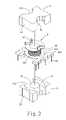
- FIG. 5is an isometric view of the invention after being assembled.
- FIG. 4is an exploded and isometric view of the inductance core and its relevant element structure of the invention.
- the inventionmainly includes two portions: a core ( 1 ) and a wire frame ( 2 ).
- a center post ( 11 ) equipping at the center portion of the core ( 1 )has a containing circumferential channel ( 12 ) providing at the periphery thereof and forming naturally a surrounded circumferential side wall ( 13 ) having small area of openings ( 131 ) at the corners.
- a center hole ( 21 )providing at the center portion of the wire frame ( 2 ) has a bobbin ( 22 ) providing at the periphery thereof for the winding of a coil ( 221 ).
- a salient lead-out seat ( 23 )providing at the corners of the wire frame ( 2 ) has a brazing post ( 231 ) extending on the same side at each of the lead-out seat ( 23 ) and connecting respectively to the drawing head drawn from a coil ( 221 ).
- FIG. 5is an isometric view of the invention after being assembled.
- the two cores ( 1 )insert in opposite manner into the center hole ( 21 ) of the wire frame ( 2 ).
- the two cores ( 1 )make use of the two containing circumferential channels ( 12 ) to contain the wire frame ( 2 ) and make each of the lead-out seat ( 23 ) stretch out through each of the opening ( 131 ).
- the core ( 1 )by the use of the circumferential side wall ( 13 ) forms an circumferentially surrounded integral covering at the periphery of the coil ( 221 ) of the wire frame ( 2 ) leaving only a small area of exposure at each of the opening ( 131 ). Therefore, as compare with the conventional relevant structure, the magnetic leakage and efficiency of the inductance or the transformer of the invention have prominent improvement.
Landscapes
- Engineering & Computer Science (AREA)
- Power Engineering (AREA)
- Microelectronics & Electronic Packaging (AREA)
- Coils Or Transformers For Communication (AREA)
Abstract
Description
1. Field of the Invention
The invention relates to an improved structure of inductance core and wire frame, and more particularly, to a core structure that can effectively increase the covering area of the core with respect to the coil, lessen the inductance leakage and improve the efficiency of inductance device.
2. Description of the Prior Art
As shown inFIG. 1 , the core (5) of a conventional core structure of the inductance or the transformer appears mainly in E-shape. The core (5) includes a center post (51) and two side posts (53) that are salient in the same direction and disposed at the center and at the ends thereof respectively, as well as recessed portions (52) positioned between the center post (51) and the side posts (53). A wire frame (6), being accommodating the core (5) for assembling into an inductance or a transformer, has a center hole (61) at the center portion thereof. The center hole (61) has a bobbin (62) at the periphery thereof for the winding of a coil (621). Brazing posts (63) having drawing heads (not shown in the Figure) for pulling out the wire (not shown in the Figure) from the coil (621) make the center posts (51) of the two cores (5) insert into the center hole (61) of the wire frame (6). The center posts (51) then contact each other at their ends, and have their recessed portions (52) containing respectively the coils (621) at the periphery of the center hole (61). In the meantime, each of the side posts (53) of the two cores (5) forms a magnetic loop on the inner side of the coil (621) accommodating the center posts (51) at the two outer sides of the coil (621). However, since the covering area of the side posts (53) of the core (5) of the above-mentioned inductance or transformer is rather small, a large portion of the coil (621) of these kinds of structure exposes to the air. This will result in serious inductance leakage of the inductance or the transformer and will hardly improve the magnetic-induction efficiency.
Shown inFIG. 2 andFIG. 3 are relatively progressive structures of the prior art. A center hole (41) having a bobbin (42) at the periphery thereof for the winding of a coil (421) is provided at the center of the wire frame (4) of the structure. Moreover, extended portions (431) are also provided at both ends of the wire frame (4) to connect to the center section of two bus panels (432) having brazing posts (43) of the drawing head (not shown in the Figure) of lead-out coil (421). What is more, a center post (31) provided at the center of the core (3) has a containing channel (32) with side recesses (331) on the two opposite sides thereof. This makes the periphery of the containing channel (32) form two opposite side walls (33). When it comes to assembling, the two cores (3), after the center posts (31) inserting into the center hole (41), contact each other, and the containing channel (32) contains the bobbin (42) of the coil (421). In the meantime, the two extended portions (431) extend out through the side recesses (331) such that the bus panels (432) and the brazing posts (43) maintain at the location outside the core (3). A magnetic loop can be formed at the periphery of the bobbin (421) by the use of the side walls (33) accommodating the center posts (31). However, although this kind of inductance or transformer structure has a relatively large area of core covering as comparing with the above-mentioned prior art, there are still large areas of side recesses (331) that make the coil (421) expose to the air. Therefore, there are still some rooms for improving the magnetic leakage and efficiency for the inductance or the transformer.
In light of the above-mentioned disadvantages of the prior arts, the invention provides an improved structure of inductance core and wire frame that can effectively increase the covering area of the core with respect to the coil, lessen the inductance leakage and improve the efficiency of inductance device. It aims to ameliorate at least some of the disadvantages of the prior art or to provide a useful alternative. The objective of the invention is to provide a center post at the center portion of the core. A containing circumferential channel is also provided at the periphery of the center post to make the outer circumference of the containing circumferential channel form a surrounded circumferential side wall that has small area of indentation openings at the end corners only. A center hole is also provided at the center portion of the wire frame that accommodates the center post, and a bobbin for the winding of the coil is further provided at the outer circumference of the center hole. A salient lead-out seat is provided at the end corner of the wire frame, and brazing posts are also provided on the same side at the upper edge of each of the lead-out seat to connect to the drawing head of the coil. By the use of the center post of the core embedding into the center hole of the wire frame, as well as making use of the containing circumferential channel to contain the wire frame, each of the lead-out seat of the wire frame can stretch out through the openings of the core. The magnetic leakage can be lessened and the inductance efficiency can be improved by making use of the circumferential side wall to form an integral surrounded covering. The accomplishment of this and other objectives of the invention will become apparent from the following description and its accompanying drawings of which:
It will become apparent to those people skilled in the art that various modifications and variations can be made to the structure of the invention without departing from the scope or spirit of the invention. In view of the foregoing description, it is intended that all the modifications and variation fall within the scope of the following appended claims and their equivalents.
Claims (2)
1. An improved structure of inductance core and wire frame comprising two portions: a core and a wire frame; a center post equipping at the center portion of the core has a containing circumferential channel providing at the periphery thereof; a center hole providing at the center portion of the wire frame has a bobbin providing at the periphery thereof for the winding of a coil; by the use of the center posts, the two cores insert in opposite manner into the center hole of the wire frame; the improved structure is characterized by that:
a circumferential side wall is provided at the periphery of the containing circumferential channel of the core, and an opening is provided at each corner of the containing circumferential channel; in addition, a salient lead-out seat is provided at each corner of the wire frame stretching out through each of the opening and making the circumferential side wall form an circumferentially surrounded integral covering at the periphery of the coil of the wire frame.
2. The improved structure of inductance core and wire frame as claimed inclaim 1 , wherein a brazing post is provided at each of the lead-out seat to connect respectively to the drawing head drawn from a coil.
Priority Applications (1)
| Application Number | Priority Date | Filing Date | Title |
|---|---|---|---|
| US11/224,483US7061358B1 (en) | 2005-09-12 | 2005-09-12 | Structure of inductance core and wire frame |
Applications Claiming Priority (1)
| Application Number | Priority Date | Filing Date | Title |
|---|---|---|---|
| US11/224,483US7061358B1 (en) | 2005-09-12 | 2005-09-12 | Structure of inductance core and wire frame |
Publications (1)
| Publication Number | Publication Date |
|---|---|
| US7061358B1true US7061358B1 (en) | 2006-06-13 |
Family
ID=36576486
Family Applications (1)
| Application Number | Title | Priority Date | Filing Date |
|---|---|---|---|
| US11/224,483Expired - LifetimeUS7061358B1 (en) | 2005-09-12 | 2005-09-12 | Structure of inductance core and wire frame |
Country Status (1)
| Country | Link |
|---|---|
| US (1) | US7061358B1 (en) |
Cited By (51)
| Publication number | Priority date | Publication date | Assignee | Title |
|---|---|---|---|---|
| US20080024259A1 (en)* | 2002-04-18 | 2008-01-31 | Sriram Chandrasekaran | Extended E Matrix Integrated Magnetics (MIM) Core |
| US20080111657A1 (en)* | 2004-08-19 | 2008-05-15 | Vivek Mehrotra | Vertical Winding Structures for Planar Magnetic Switched-Mode Power Converters |
| US20080130322A1 (en)* | 2006-12-01 | 2008-06-05 | Artusi Daniel A | Power system with power converters having an adaptive controller |
| US20080232141A1 (en)* | 2006-12-01 | 2008-09-25 | Artusi Daniel A | Power System with Power Converters Having an Adaptive Controller |
| US20080310190A1 (en)* | 2005-02-08 | 2008-12-18 | Sriram Chandrasekaran | Power Converter Employing Integrated Magnetics with a Current Multiplier Rectifier and Method of Operating the Same |
| US20080316779A1 (en)* | 2007-06-19 | 2008-12-25 | Chandrasekaran Jayaraman | System and method for estimating input power for a power processing circuit |
| US20090115561A1 (en)* | 2007-11-06 | 2009-05-07 | Antony Brinlee | Planar core structure |
| US20090295529A1 (en)* | 2008-05-28 | 2009-12-03 | Arturo Silva | Cross-core transformer |
| US20100039202A1 (en)* | 2008-08-18 | 2010-02-18 | Delta Electronics, Inc. | Magnetic element |
| US7675758B2 (en) | 2006-12-01 | 2010-03-09 | Flextronics International Usa, Inc. | Power converter with an adaptive controller and method of operating the same |
| CN101170010B (en)* | 2007-08-14 | 2010-06-09 | 康舒科技股份有限公司 | Thin transformer and transformer assembly |
| US20100156584A1 (en)* | 2008-12-24 | 2010-06-24 | Tdk Corporation | Coil component |
| US7876191B2 (en) | 2005-02-23 | 2011-01-25 | Flextronics International Usa, Inc. | Power converter employing a tapped inductor and integrated magnetics and method of operating the same |
| US7889517B2 (en) | 2006-12-01 | 2011-02-15 | Flextronics International Usa, Inc. | Power system with power converters having an adaptive controller |
| US20110050378A1 (en)* | 2009-08-28 | 2011-03-03 | Tdk Corporation | Coil component having wire-support member |
| US20110193673A1 (en)* | 2010-02-06 | 2011-08-11 | Delta Electronics, Inc. | Magnetic element and bobbin thereof |
| WO2011147105A1 (en)* | 2010-05-26 | 2011-12-01 | 深圳市欣锐特科技有限公司 | Transformer as well as switching power supply and led fluorescent lamp applying same |
| US8125205B2 (en) | 2006-08-31 | 2012-02-28 | Flextronics International Usa, Inc. | Power converter employing regulators with a coupled inductor |
| CN101656142B (en)* | 2008-08-21 | 2012-09-19 | 台达电子工业股份有限公司 | magnetic element |
| US8502520B2 (en) | 2007-03-14 | 2013-08-06 | Flextronics International Usa, Inc | Isolated power converter |
| US8514593B2 (en) | 2009-06-17 | 2013-08-20 | Power Systems Technologies, Ltd. | Power converter employing a variable switching frequency and a magnetic device with a non-uniform gap |
| US8520420B2 (en) | 2009-12-18 | 2013-08-27 | Power Systems Technologies, Ltd. | Controller for modifying dead time between switches in a power converter |
| US8520414B2 (en) | 2009-01-19 | 2013-08-27 | Power Systems Technologies, Ltd. | Controller for a power converter |
| US8638578B2 (en) | 2009-08-14 | 2014-01-28 | Power System Technologies, Ltd. | Power converter including a charge pump employable in a power adapter |
| US8643222B2 (en) | 2009-06-17 | 2014-02-04 | Power Systems Technologies Ltd | Power adapter employing a power reducer |
| US8767418B2 (en) | 2010-03-17 | 2014-07-01 | Power Systems Technologies Ltd. | Control system for a power converter and method of operating the same |
| US8787043B2 (en) | 2010-01-22 | 2014-07-22 | Power Systems Technologies, Ltd. | Controller for a power converter and method of operating the same |
| US8792257B2 (en) | 2011-03-25 | 2014-07-29 | Power Systems Technologies, Ltd. | Power converter with reduced power dissipation |
| US8792256B2 (en) | 2012-01-27 | 2014-07-29 | Power Systems Technologies Ltd. | Controller for a switch and method of operating the same |
| US20140266559A1 (en)* | 2013-03-13 | 2014-09-18 | Yujing Technology Co., Ltd. | Structure of transformer's iron core |
| US8976549B2 (en) | 2009-12-03 | 2015-03-10 | Power Systems Technologies, Ltd. | Startup circuit including first and second Schmitt triggers and power converter employing the same |
| CN104505223A (en)* | 2014-08-27 | 2015-04-08 | 江门市尚品科技研发电子有限公司 | Improved structure of magnetic cores and winding framework |
| US9019061B2 (en) | 2009-03-31 | 2015-04-28 | Power Systems Technologies, Ltd. | Magnetic device formed with U-shaped core pieces and power converter employing the same |
| US9077248B2 (en) | 2009-06-17 | 2015-07-07 | Power Systems Technologies Ltd | Start-up circuit for a power adapter |
| US9088216B2 (en) | 2009-01-19 | 2015-07-21 | Power Systems Technologies, Ltd. | Controller for a synchronous rectifier switch |
| US9099232B2 (en) | 2012-07-16 | 2015-08-04 | Power Systems Technologies Ltd. | Magnetic device and power converter employing the same |
| US9106130B2 (en) | 2012-07-16 | 2015-08-11 | Power Systems Technologies, Inc. | Magnetic device and power converter employing the same |
| US9190898B2 (en) | 2012-07-06 | 2015-11-17 | Power Systems Technologies, Ltd | Controller for a power converter and method of operating the same |
| US9197132B2 (en) | 2006-12-01 | 2015-11-24 | Flextronics International Usa, Inc. | Power converter with an adaptive controller and method of operating the same |
| US9214264B2 (en) | 2012-07-16 | 2015-12-15 | Power Systems Technologies, Ltd. | Magnetic device and power converter employing the same |
| US9240712B2 (en) | 2012-12-13 | 2016-01-19 | Power Systems Technologies Ltd. | Controller including a common current-sense device for power switches of a power converter |
| US9246391B2 (en) | 2010-01-22 | 2016-01-26 | Power Systems Technologies Ltd. | Controller for providing a corrected signal to a sensed peak current through a circuit element of a power converter |
| US9300206B2 (en) | 2013-11-15 | 2016-03-29 | Power Systems Technologies Ltd. | Method for estimating power of a power converter |
| US9379629B2 (en) | 2012-07-16 | 2016-06-28 | Power Systems Technologies, Ltd. | Magnetic device and power converter employing the same |
| CN105845394A (en)* | 2016-06-20 | 2016-08-10 | 合肥市菲力克斯电子科技有限公司 | Assembled high-frequency transformer formwork capable of reinforcing pins |
| CN105845390A (en)* | 2016-06-20 | 2016-08-10 | 合肥市菲力克斯电子科技有限公司 | Combined high-frequency transformer skeleton |
| US20170047159A1 (en)* | 2014-03-14 | 2017-02-16 | Sharp Kabushiki Kaisha | Transformer and power source device |
| CN106683854A (en)* | 2017-03-20 | 2017-05-17 | 东莞市大忠电子有限公司 | A Non-Uniform High Frequency Transformer Skeleton |
| US20210098179A1 (en)* | 2019-10-01 | 2021-04-01 | Tdk Electronics Ag | Core Component |
| US11183776B2 (en)* | 2019-01-28 | 2021-11-23 | Chyng Hong Electronic Co., Ltd. | Output wire joining structure of winding seat for transformer or inductor |
| CN114050026A (en)* | 2021-11-30 | 2022-02-15 | 杭州云电科技能源有限公司 | Magnetic assembly, manufacturing method thereof, power module and switching power supply |
Citations (3)
| Publication number | Priority date | Publication date | Assignee | Title |
|---|---|---|---|---|
| US4549158A (en)* | 1978-11-09 | 1985-10-22 | Tdk Corporation | Inductance element |
| US5359313A (en)* | 1991-12-10 | 1994-10-25 | Toko, Inc. | Step-up transformer |
| US6714111B2 (en)* | 2001-05-25 | 2004-03-30 | Minebea Co., Ltd. | Inverter transformer |
- 2005
- 2005-09-12USUS11/224,483patent/US7061358B1/ennot_activeExpired - Lifetime
Patent Citations (3)
| Publication number | Priority date | Publication date | Assignee | Title |
|---|---|---|---|---|
| US4549158A (en)* | 1978-11-09 | 1985-10-22 | Tdk Corporation | Inductance element |
| US5359313A (en)* | 1991-12-10 | 1994-10-25 | Toko, Inc. | Step-up transformer |
| US6714111B2 (en)* | 2001-05-25 | 2004-03-30 | Minebea Co., Ltd. | Inverter transformer |
Cited By (72)
| Publication number | Priority date | Publication date | Assignee | Title |
|---|---|---|---|---|
| US7633369B2 (en) | 2002-04-18 | 2009-12-15 | Flextronics International Usa, Inc. | Extended E matrix integrated magnetics (MIM) core |
| US8134443B2 (en) | 2002-04-18 | 2012-03-13 | Flextronics International Usa, Inc. | Extended E matrix integrated magnetics (MIM) core |
| US20080024259A1 (en)* | 2002-04-18 | 2008-01-31 | Sriram Chandrasekaran | Extended E Matrix Integrated Magnetics (MIM) Core |
| US20080111657A1 (en)* | 2004-08-19 | 2008-05-15 | Vivek Mehrotra | Vertical Winding Structures for Planar Magnetic Switched-Mode Power Converters |
| US7554430B2 (en)* | 2004-08-19 | 2009-06-30 | Flextronics International Usa, Inc. | Vertical winding structures for planar magnetic switched-mode power converters |
| US20080310190A1 (en)* | 2005-02-08 | 2008-12-18 | Sriram Chandrasekaran | Power Converter Employing Integrated Magnetics with a Current Multiplier Rectifier and Method of Operating the Same |
| US7675764B2 (en) | 2005-02-08 | 2010-03-09 | Flextronics International Usa, Inc. | Power converter employing integrated magnetics with a current multiplier rectifier and method of operating the same |
| US7876191B2 (en) | 2005-02-23 | 2011-01-25 | Flextronics International Usa, Inc. | Power converter employing a tapped inductor and integrated magnetics and method of operating the same |
| US8125205B2 (en) | 2006-08-31 | 2012-02-28 | Flextronics International Usa, Inc. | Power converter employing regulators with a coupled inductor |
| US7675758B2 (en) | 2006-12-01 | 2010-03-09 | Flextronics International Usa, Inc. | Power converter with an adaptive controller and method of operating the same |
| US7667986B2 (en) | 2006-12-01 | 2010-02-23 | Flextronics International Usa, Inc. | Power system with power converters having an adaptive controller |
| US20080130322A1 (en)* | 2006-12-01 | 2008-06-05 | Artusi Daniel A | Power system with power converters having an adaptive controller |
| US7675759B2 (en) | 2006-12-01 | 2010-03-09 | Flextronics International Usa, Inc. | Power system with power converters having an adaptive controller |
| US20080232141A1 (en)* | 2006-12-01 | 2008-09-25 | Artusi Daniel A | Power System with Power Converters Having an Adaptive Controller |
| US8477514B2 (en) | 2006-12-01 | 2013-07-02 | Flextronics International Usa, Inc. | Power system with power converters having an adaptive controller |
| US7889517B2 (en) | 2006-12-01 | 2011-02-15 | Flextronics International Usa, Inc. | Power system with power converters having an adaptive controller |
| US9197132B2 (en) | 2006-12-01 | 2015-11-24 | Flextronics International Usa, Inc. | Power converter with an adaptive controller and method of operating the same |
| US8502520B2 (en) | 2007-03-14 | 2013-08-06 | Flextronics International Usa, Inc | Isolated power converter |
| US7906941B2 (en) | 2007-06-19 | 2011-03-15 | Flextronics International Usa, Inc. | System and method for estimating input power for a power processing circuit |
| US20080316779A1 (en)* | 2007-06-19 | 2008-12-25 | Chandrasekaran Jayaraman | System and method for estimating input power for a power processing circuit |
| CN101170010B (en)* | 2007-08-14 | 2010-06-09 | 康舒科技股份有限公司 | Thin transformer and transformer assembly |
| US7969272B2 (en)* | 2007-11-06 | 2011-06-28 | Flextronics Ap, Llc | Planar core structure |
| US8458893B2 (en)* | 2007-11-06 | 2013-06-11 | Flextronics Ap, Llc | Method for assembling a magnetic component |
| US20110232080A1 (en)* | 2007-11-06 | 2011-09-29 | Flextronics Ap, Llc | Magnetic component assembly |
| US20090115561A1 (en)* | 2007-11-06 | 2009-05-07 | Antony Brinlee | Planar core structure |
| US7948348B2 (en)* | 2008-05-28 | 2011-05-24 | Flextronics Ap, Llc | Cross-core transformer |
| US20090295529A1 (en)* | 2008-05-28 | 2009-12-03 | Arturo Silva | Cross-core transformer |
| US20100039202A1 (en)* | 2008-08-18 | 2010-02-18 | Delta Electronics, Inc. | Magnetic element |
| US8054150B2 (en)* | 2008-08-18 | 2011-11-08 | Delta Electronics, Inc. | Magnetic element |
| CN101656142B (en)* | 2008-08-21 | 2012-09-19 | 台达电子工业股份有限公司 | magnetic element |
| US20100156584A1 (en)* | 2008-12-24 | 2010-06-24 | Tdk Corporation | Coil component |
| US7952457B2 (en)* | 2008-12-24 | 2011-05-31 | Tdk Corporation | Coil component |
| US8520414B2 (en) | 2009-01-19 | 2013-08-27 | Power Systems Technologies, Ltd. | Controller for a power converter |
| US9088216B2 (en) | 2009-01-19 | 2015-07-21 | Power Systems Technologies, Ltd. | Controller for a synchronous rectifier switch |
| US9019061B2 (en) | 2009-03-31 | 2015-04-28 | Power Systems Technologies, Ltd. | Magnetic device formed with U-shaped core pieces and power converter employing the same |
| US8514593B2 (en) | 2009-06-17 | 2013-08-20 | Power Systems Technologies, Ltd. | Power converter employing a variable switching frequency and a magnetic device with a non-uniform gap |
| US8643222B2 (en) | 2009-06-17 | 2014-02-04 | Power Systems Technologies Ltd | Power adapter employing a power reducer |
| US9077248B2 (en) | 2009-06-17 | 2015-07-07 | Power Systems Technologies Ltd | Start-up circuit for a power adapter |
| US8638578B2 (en) | 2009-08-14 | 2014-01-28 | Power System Technologies, Ltd. | Power converter including a charge pump employable in a power adapter |
| US8253522B2 (en)* | 2009-08-28 | 2012-08-28 | Tdk Corporation | Coil component having wire-support member |
| US20110050378A1 (en)* | 2009-08-28 | 2011-03-03 | Tdk Corporation | Coil component having wire-support member |
| US8976549B2 (en) | 2009-12-03 | 2015-03-10 | Power Systems Technologies, Ltd. | Startup circuit including first and second Schmitt triggers and power converter employing the same |
| US8520420B2 (en) | 2009-12-18 | 2013-08-27 | Power Systems Technologies, Ltd. | Controller for modifying dead time between switches in a power converter |
| US8787043B2 (en) | 2010-01-22 | 2014-07-22 | Power Systems Technologies, Ltd. | Controller for a power converter and method of operating the same |
| US9246391B2 (en) | 2010-01-22 | 2016-01-26 | Power Systems Technologies Ltd. | Controller for providing a corrected signal to a sensed peak current through a circuit element of a power converter |
| US20110193673A1 (en)* | 2010-02-06 | 2011-08-11 | Delta Electronics, Inc. | Magnetic element and bobbin thereof |
| US8269593B2 (en)* | 2010-02-06 | 2012-09-18 | Delta Electronics, Inc. | Magnetic element and bobbin thereof |
| US8767418B2 (en) | 2010-03-17 | 2014-07-01 | Power Systems Technologies Ltd. | Control system for a power converter and method of operating the same |
| WO2011147105A1 (en)* | 2010-05-26 | 2011-12-01 | 深圳市欣锐特科技有限公司 | Transformer as well as switching power supply and led fluorescent lamp applying same |
| US8792257B2 (en) | 2011-03-25 | 2014-07-29 | Power Systems Technologies, Ltd. | Power converter with reduced power dissipation |
| US8792256B2 (en) | 2012-01-27 | 2014-07-29 | Power Systems Technologies Ltd. | Controller for a switch and method of operating the same |
| US9190898B2 (en) | 2012-07-06 | 2015-11-17 | Power Systems Technologies, Ltd | Controller for a power converter and method of operating the same |
| US9379629B2 (en) | 2012-07-16 | 2016-06-28 | Power Systems Technologies, Ltd. | Magnetic device and power converter employing the same |
| US9099232B2 (en) | 2012-07-16 | 2015-08-04 | Power Systems Technologies Ltd. | Magnetic device and power converter employing the same |
| US9106130B2 (en) | 2012-07-16 | 2015-08-11 | Power Systems Technologies, Inc. | Magnetic device and power converter employing the same |
| US9214264B2 (en) | 2012-07-16 | 2015-12-15 | Power Systems Technologies, Ltd. | Magnetic device and power converter employing the same |
| US9240712B2 (en) | 2012-12-13 | 2016-01-19 | Power Systems Technologies Ltd. | Controller including a common current-sense device for power switches of a power converter |
| US20140266559A1 (en)* | 2013-03-13 | 2014-09-18 | Yujing Technology Co., Ltd. | Structure of transformer's iron core |
| EP2779184A3 (en)* | 2013-03-13 | 2014-12-31 | Yujing Technology Co., Ltd. | Improved structure of transformer's iron core |
| US9300206B2 (en) | 2013-11-15 | 2016-03-29 | Power Systems Technologies Ltd. | Method for estimating power of a power converter |
| US20170047159A1 (en)* | 2014-03-14 | 2017-02-16 | Sharp Kabushiki Kaisha | Transformer and power source device |
| CN104505223B (en)* | 2014-08-27 | 2017-06-20 | 江门市尚品科技研发电子有限公司 | A kind of improved structure of magnetic core and bobbin |
| CN104505223A (en)* | 2014-08-27 | 2015-04-08 | 江门市尚品科技研发电子有限公司 | Improved structure of magnetic cores and winding framework |
| CN105845394A (en)* | 2016-06-20 | 2016-08-10 | 合肥市菲力克斯电子科技有限公司 | Assembled high-frequency transformer formwork capable of reinforcing pins |
| CN105845390A (en)* | 2016-06-20 | 2016-08-10 | 合肥市菲力克斯电子科技有限公司 | Combined high-frequency transformer skeleton |
| CN106683854A (en)* | 2017-03-20 | 2017-05-17 | 东莞市大忠电子有限公司 | A Non-Uniform High Frequency Transformer Skeleton |
| CN106683854B (en)* | 2017-03-20 | 2019-01-22 | 东莞市大忠电子有限公司 | Non-uniform high-frequency transformer framework |
| US11183776B2 (en)* | 2019-01-28 | 2021-11-23 | Chyng Hong Electronic Co., Ltd. | Output wire joining structure of winding seat for transformer or inductor |
| US20210098179A1 (en)* | 2019-10-01 | 2021-04-01 | Tdk Electronics Ag | Core Component |
| US11705266B2 (en)* | 2019-10-01 | 2023-07-18 | Tdk Electronics Ag | Core component |
| CN114050026A (en)* | 2021-11-30 | 2022-02-15 | 杭州云电科技能源有限公司 | Magnetic assembly, manufacturing method thereof, power module and switching power supply |
| CN114050026B (en)* | 2021-11-30 | 2024-06-11 | 杭州云电科技能源有限公司 | Magnetic assembly, manufacturing method thereof, power module and switching power supply |
Similar Documents
| Publication | Publication Date | Title |
|---|---|---|
| US7061358B1 (en) | Structure of inductance core and wire frame | |
| US6583697B2 (en) | Transformer | |
| JP5711327B2 (en) | Transformer | |
| US20080024262A1 (en) | Transformer with insulating structure | |
| US20110037554A1 (en) | Vertical Double Deck Transformer for Power Supply | |
| US9959970B2 (en) | Resonant high current density transformer with improved structure | |
| US20140266559A1 (en) | Structure of transformer's iron core | |
| JP4805440B2 (en) | Inductance parts | |
| JP4038957B2 (en) | Transformer | |
| JP6713335B2 (en) | Trance | |
| JPH0828300B2 (en) | Trance | |
| US20070057756A1 (en) | Structure of inductance core | |
| JP2005303229A (en) | Trance | |
| JP3430144B2 (en) | Small transformer with cover | |
| JP3409009B2 (en) | Switching transformer | |
| JP2004087742A (en) | Transformer | |
| JP3849947B1 (en) | Ferrite core | |
| CN209216712U (en) | Magnetic assembly and power supply thereof | |
| JPH10261525A (en) | Trance | |
| JPH0864435A (en) | Small-sized transformer | |
| JPH0338818Y2 (en) | ||
| JPH0655229U (en) | Inductor and core holder used for this | |
| JPS5812427Y2 (en) | transformer | |
| CN119181573A (en) | Resonant inductor integrated LLC transformer | |
| JP3065501U (en) | Electric circuit device |
Legal Events
| Date | Code | Title | Description |
|---|---|---|---|
| STCF | Information on status: patent grant | Free format text:PATENTED CASE | |
| FPAY | Fee payment | Year of fee payment:4 | |
| FPAY | Fee payment | Year of fee payment:8 | |
| MAFP | Maintenance fee payment | Free format text:PAYMENT OF MAINTENANCE FEE, 12TH YR, SMALL ENTITY (ORIGINAL EVENT CODE: M2553) Year of fee payment:12 |