US7061139B2 - System for providing assured power to a critical load - Google Patents
System for providing assured power to a critical loadDownload PDFInfo
- Publication number
- US7061139B2 US7061139B2US10/255,921US25592102AUS7061139B2US 7061139 B2US7061139 B2US 7061139B2US 25592102 AUS25592102 AUS 25592102AUS 7061139 B2US7061139 B2US 7061139B2
- Authority
- US
- United States
- Prior art keywords
- power
- power source
- inverter
- fuel cell
- load
- Prior art date
- Legal status (The legal status is an assumption and is not a legal conclusion. Google has not performed a legal analysis and makes no representation as to the accuracy of the status listed.)
- Expired - Lifetime, expires
Links
Images


Classifications
- H—ELECTRICITY
- H02—GENERATION; CONVERSION OR DISTRIBUTION OF ELECTRIC POWER
- H02J—CIRCUIT ARRANGEMENTS OR SYSTEMS FOR SUPPLYING OR DISTRIBUTING ELECTRIC POWER; SYSTEMS FOR STORING ELECTRIC ENERGY
- H02J9/00—Circuit arrangements for emergency or stand-by power supply, e.g. for emergency lighting
- H—ELECTRICITY
- H02—GENERATION; CONVERSION OR DISTRIBUTION OF ELECTRIC POWER
- H02J—CIRCUIT ARRANGEMENTS OR SYSTEMS FOR SUPPLYING OR DISTRIBUTING ELECTRIC POWER; SYSTEMS FOR STORING ELECTRIC ENERGY
- H02J3/00—Circuit arrangements for AC mains or AC distribution networks
- H02J3/28—Arrangements for balancing of the load in a network by storage of energy
- H02J3/32—Arrangements for balancing of the load in a network by storage of energy using batteries with converting means
- H—ELECTRICITY
- H02—GENERATION; CONVERSION OR DISTRIBUTION OF ELECTRIC POWER
- H02J—CIRCUIT ARRANGEMENTS OR SYSTEMS FOR SUPPLYING OR DISTRIBUTING ELECTRIC POWER; SYSTEMS FOR STORING ELECTRIC ENERGY
- H02J7/00—Circuit arrangements for charging or depolarising batteries or for supplying loads from batteries
- H—ELECTRICITY
- H02—GENERATION; CONVERSION OR DISTRIBUTION OF ELECTRIC POWER
- H02J—CIRCUIT ARRANGEMENTS OR SYSTEMS FOR SUPPLYING OR DISTRIBUTING ELECTRIC POWER; SYSTEMS FOR STORING ELECTRIC ENERGY
- H02J9/00—Circuit arrangements for emergency or stand-by power supply, e.g. for emergency lighting
- H02J9/04—Circuit arrangements for emergency or stand-by power supply, e.g. for emergency lighting in which the distribution system is disconnected from the normal source and connected to a standby source
- H02J9/06—Circuit arrangements for emergency or stand-by power supply, e.g. for emergency lighting in which the distribution system is disconnected from the normal source and connected to a standby source with automatic change-over, e.g. UPS systems
- H02J9/062—Circuit arrangements for emergency or stand-by power supply, e.g. for emergency lighting in which the distribution system is disconnected from the normal source and connected to a standby source with automatic change-over, e.g. UPS systems for AC powered loads
- H—ELECTRICITY
- H02—GENERATION; CONVERSION OR DISTRIBUTION OF ELECTRIC POWER
- H02J—CIRCUIT ARRANGEMENTS OR SYSTEMS FOR SUPPLYING OR DISTRIBUTING ELECTRIC POWER; SYSTEMS FOR STORING ELECTRIC ENERGY
- H02J2300/00—Systems for supplying or distributing electric power characterised by decentralized, dispersed, or local generation
- H02J2300/30—The power source being a fuel cell
- Y—GENERAL TAGGING OF NEW TECHNOLOGICAL DEVELOPMENTS; GENERAL TAGGING OF CROSS-SECTIONAL TECHNOLOGIES SPANNING OVER SEVERAL SECTIONS OF THE IPC; TECHNICAL SUBJECTS COVERED BY FORMER USPC CROSS-REFERENCE ART COLLECTIONS [XRACs] AND DIGESTS
- Y02—TECHNOLOGIES OR APPLICATIONS FOR MITIGATION OR ADAPTATION AGAINST CLIMATE CHANGE
- Y02B—CLIMATE CHANGE MITIGATION TECHNOLOGIES RELATED TO BUILDINGS, e.g. HOUSING, HOUSE APPLIANCES OR RELATED END-USER APPLICATIONS
- Y02B90/00—Enabling technologies or technologies with a potential or indirect contribution to GHG emissions mitigation
- Y02B90/10—Applications of fuel cells in buildings
Definitions
- This inventionrelates generally to power systems, and more particularly to power systems for providing an assured, or uninterruptible, supply of electrical power to one or more critical loads. More particularly still, the invention relates to such power systems employing fuel cells as a source of electrical power.
- ITIInformation Technology Industry Council
- CBEMAComputer Business Equipment Manufacturers Association
- a supply of power with interruptions or transfers of no greater than 8.3 ms durationmay be referred to as being “seamless”, “substantially continuous”, or “substantially uninterrupted”.
- UPSuninterruptible power supply
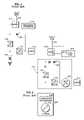
- the utility grid power supplynormally appears on conductor 110 , and is passed via normally-closed contacts of a 3-pole transfer switch 112 to a rectifier 120 , which supplies the critical loads 114 via an inverter 122 .
- a backup battery 116is provided to supply immediate power of limited duration, and an emergency electrical generator 118 is then connected to the other contact of transfer switch 112 to follow-up with a longer term temporary supply.
- a high speed switch 124 connected between the transfer switch 112 and the loads 114operates as a bypass switch to provide temporary power if the inverter 122 or rectifier 120 must be serviced. Because the grid and loads are not normally directly connected, but rather the power to the loads is required to pass through a pair of converters with the aid of the UPS battery, this type of UPS is termed an “on-line” or “double conversion” type. This arrangement, though effective, requires a number of costly components that are in use only during the intervals when the utility grid power is unsatisfactory.
- One such power sourcemay be the utility grid 210 .
- Another sourcemay be the fuel cell generator power plant 218 .
- a transfer switching arrangement 212enables one or the other of the utility grid 210 and the fuel cell 218 to normally provide the power to drive the motor-generator 230 .
- This type of uninterruptible power supplyis also of the “on-line” or “double conversion” type inasmuch as the grid is not directly connected to the loads 214 , but acts through the rectifier and inverter converters and the flywheel and/or fuel cells to energize motor-generator 230 which in turn provides uninterrupted power.
- the fuel cell 218is configured to operate in a grid connect (G/C) mode with the utility grid 210 for system economy, so in grid connected mode both the grid and the fuel cell supply the “grid” terminals of the transfer switch.
- G/Cgrid connect
- the fuel cell 218is intended to serve as the continuing power source for the motor-generator 230 .
- the fuel cell 218must reconfigure from a “grid connect” (G/C) mode of operation to a “grid independent” (G/I) mode.
- the power conditioning system (PCS) portion of the fuel cell 218includes associated inverters, switching transistors and breakers (not shown) that effect the conversion of DC power to AC power and that govern the fundamental G/C and G/I modes of fuel cell operation. That mode transition (from G/C to G/I) has typically required the fuel cell 218 and transfer switch 212 to interrupt power generation for up to 5 seconds. Such interruption is not “seamless”, and would be of unacceptable duration for critical computer loads 214 . Accordingly, a backup flywheel power source 216 provides immediate power of limited duration (similar to the battery source 116 in FIG. 1 ) to the motor-generator 230 at least during such mode conversions.
- That backup power source 216is a flywheel 236 driving a bi-directional AC/DC converter 238 .
- the converter 238keeps the flywheel spinning during normal operation, and discharges the flywheel 236 during backup operation.
- the various transfer switches used in the transfer switching arrangement 212 and in the uninterruptable power system module 231may be electromechanical, static, or a combination thereof, and serve to effect the various power switching functions.
- the Power System of the abovementioned PCT application/U.S. patentmay provide a substantially uninterrupted source of power to various critical loads and may advantageously employ fuel cells as one of the main sources of the power, it nevertheless requires the use of considerable additional equipment that is complex and costly.
- the separate motor-generator 230 , and the backup power source 216 which includes the flywheel 236 /converter 238 combinationrepresent necessary, but expensive, components in order to assure the degree of power continuity sought and required.
- UPSis of the “stand-by” type wherein the grid is directly connected to the loads and a stand-by UPS remains idle, even if connected to the loads, until a switch disconnects the grid from the loads.
- An example of such a systemis disclosed in U.S. Pat. No. 6,011,324.
- the fuel cell and associated invertersare normally connected to the loads, but in an idle standby mode while the grid supplies power directly to the loads.
- the fuel cellis rapidly brought to full output power and a solid state switch disconnects the grid.
- a number of costly components, including the fuel cellare in use only during the intervals when the utility grid power is unsatisfactory.
- a relatively economical and reliable power systemfor providing substantially uninterrupted electric power to one or more critical loads.
- a first power sourcecomprising at least one, and possibly multiple, fuel cell power plants, normally provides sufficient power to supply at least the critical loads.
- a second power sourcesuch as the utility grid, also provides sufficient power to supply the critical loads.
- the fuel cell power plant(s)is/are adapted to be, and is/are, normally substantially continuously connected to the critical loads and are normally substantially continuously providing significant power to at least the critical loads.
- a high-speed isolation switch, or static switchoperates to rapidly and seamlessly connect and disconnect the utility grid to the critical load(s) and to the fuel cell power plant(s), for economical continuous usage of the fuel cell power plant(s).
- the static switchmay be one or more silicon controlled rectifiers (SCRs), or thyristors.
- Solid-state switch controlsoperate to rapidly switch the static switch in 4 ms, or less, to make seamless transfers between the first and second power sources. This switching speed is significantly faster than is obtained with conventional line commutation of thyristors.
- Further control electronicsprovide high-speed transitions (less than about 4 ms) in the operating modes of the power conditioning system (PCS) inverters associated with each fuel cell power plant(s). This assures that the fuel cell mode transitions, heretofore normally slow, are at a speed comparable to that of the static switch so as to provide substantially seamless power transfers of and between the first and second power sources. This allows continuous productive operation of the fuel cell power plant(s).
- PCSpower conditioning system
- one or more power assurance measuresare provided in association with at least one of the grid and the fuel cell power plant power sources.
- One such power assurance measureis the inclusion of a line filter in the grid supply to prevent voltage spikes from appearing at the critical load while the static switch is opening.
- Another such power assurance measureis the re-directed connection of the grid to the fuel cell power plant inverter, via a rectifier, which assures the load of a redundant power source in the event the particular fuel cell is out of service and also adds a degree of isolation between the grid and load.
- Yet another such power assurance measureis the connection of a stored energy device to the inverter to ride through temporary grid interruptions when the particular fuel cell is out of service or, when only the fuel cell is operating, to temporarily supplement the fuel cell's power output when the load experiences an instantaneous increase that is momentarily beyond the fuel cell's capacity and thus causes a temporary decrease in voltage.
- FIG. 1is a simplified schematic block diagram of one type of uninterruptible power supply in accordance with the prior art
- FIG. 2is a simplified schematic block diagram of an uninterruptible power supply employing fuel cell power plants in accordance with the prior art
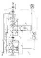
- FIG. 3is schematic block diagram of a power system employing a fuel cell power plant and grid interconnected in accordance with the invention to assure uninterrupted power to a critical load;
- FIG. 4is a schematic block diagram illustrating the static switch in greater detail.
- FIG. 5is a table of the operational mode states of the fuel cell breaker in association with fuel cell and rectifier operating states.
- FIGS. 1 and 2depict prior types of uninterrupted power systems as previously described in the Background Art.
- FIG. 3there is depicted a schematic block diagram, partly in detail, of a power system 8 in accordance with the invention.
- the power system 8is connected to utility grid bus 10 , and employs one or more fuel cell power plant(s) 18 at a site, for supplying 3-phase power substantially continuously to and through load contactors (not shown), to load(s) 14 , usually also at the site.
- load contactorsnot shown
- load(s) 14usually also at the site.
- a “one line” diagram, or representationis used herein to depict the 3-phase supply lines, as well as their included switches, etc.
- the grid 10 , the fuel cell power plant(s) 18 , and the load(s) 14are interconnected and controlled through a site management system (SMS), generally represented by the broken line block, or grouping, 11 .
- SMSsite management system
- the load(s) 14typically include a number of individual customer loads, at least some of which require a substantially continuous supply of power and are thus deemed “critical loads”.
- the critical loads 14are typically computers, control devices employing computers, and/or electronic data processing devices.
- the portions of the schematic carrying the relatively higher voltage/current/power to the load(s) 14are bolded, in contrast with the lower-voltage, control portions of the system 8 .
- the utility grid bus 10normally provides power at 480 V AC and 60 Hz, as does the fuel cell power plant(s) 18 via lead, or bus, 15 .
- Switching geargenerally designated 12 , serves to interconnect the fuel cell(s) 18 , the load(s) 14 and the utility grid 10 . In this way, the fuel cell power plant(s) 18 are available and connected for supplying electrical power on a full time basis to the loads 14 and/or to the utility grid 10 , for economical usage of the fuel cell(s).
- the switching gear 12includes a high-speed isolation switch, such as static switch module 17 , for selectively connecting and disconnecting the utility grid bus 10 to the loads 14 and to the fuel cell power plant(s) 18 , as will be described.
- the static switch module 17includes a 3-pole electrically operated static switch 19 rated at 2000 amperes and capable of performing seamless switching transfer of power in about 1 ⁇ 4 cycle (about 4 ms).
- the switching gear 12further includes several inter-tie or breaker switches 21 , 21 A, 23 , 23 A, and isolation switch 25 , for further selectively connecting and disconnecting the fuel cell power plant(s) 18 , loads 14 , utility grid bus 10 and static switch module 17 , relative to one another, primarily to isolate the static switch 19 for servicing and continue to provide power to the load(s) 14 .
- a secondary purposeis to allow large fault currents to flow through breaker 23 A instead of static switch 19 if such a fault in the load 14 should occur.
- each fuel cell power plant 18may be a 200 kw UTC Fuel Cell PC25TMC power plant, for providing up to 200 kilowatt of power.
- the fuel cell power plant 18includes a fuel cell assembly 60 and a power conditioning system (PCS) 62 that contains a solid-state inverter 64 that converts DC power to AC power at the desired voltage and frequency.
- PCSpower conditioning system
- Control of and by the PCSfurther enables conversion of the mode of operation of a fuel cell power plant 18 from G/C to G/I, and vice versa, as will be described in greater detail.
- the variable controlled by the PCS 62is power delivered (both real and reactive).
- the variables controlledare output voltage and frequency, and, if multiple power plants 18 are involved, phase.
- a controllable circuit breaker 80is connected to the output of the inverter 64 and is normally closed when fuel cell 60 is operating, to provide power output from the respective power plant 18 .
- the output of the fuel cell power plant(s) 18is connected to bus 15 , which is connected through a delta-to-wye transformer 27 and bus 15 ′ to the switching gear 12 .
- the transformer 27provides a separately derived neutral/ground system for the load 14 , and also provides isolation between the fuel cell PCS and the load 14 and/or the utility grid bus 10 .
- a site supervisory control (SSC) 29provides the operator interface for the system 8 and may be responsible for control of the system, usually at a high level.
- the SSC 29allows the operator to issue high level commands such as “start”, “stop”, and the like.
- the SSC 29may include one or more programmable logic controllers, data processors, computers, sensors, etc. to effect the control of the various components and functions of the system 8 .
- An operator console 32provides a display and input capability for the SSC 29 .
- the SSC 29may also provide some system control of switching gear 12 , as through a link 52 , with principal local control of that switching gear occurring automatically by the static switch 19 .
- the SSC 29may serve as the control intermediary for control of static switch 19 if a/the fuel cell 60 is not available for power generation and for control of circuit breaker 80 of a respective power plant 18 , as will be described.
- SMC 31for providing direct control of the PCS 62 of the fuel cell power plant(s) 18 , in response to signals from the static switch module 17 , as well as a grid voltage reference signal 10 ′ described below.
- the SMC 31also may be composed of computers and associated sensors and control circuitry.
- the SMC 31may be viewed and considered as an included portion of the SMS 11 .
- Control bus 33exchanges control signals between the SMC 31 and the PCS 62 of the fuel cell power plant(s) 18 .
- Control signalsare also exchanged between the SSC 29 and the fuel cell 60 and PCS 62 including circuit breaker 80 , of the fuel cell power plant(s) 18 , via control bus 35 .
- Control signalsare exchanged between the SMC 31 and the static switch module 17 via control bus 40 .
- a voltage, or potential, transformer 37senses the 480 V ac grid voltage and communicates the stepped-down 120 V ac value, via bus 10 ′, to the SMC 31 and the static switch module 17 for the purpose of providing control signals indicative of the grid's voltage, phase and frequency.
- the depicted location and quantity of transformer(s) 37is mainly symbolic, and it should be understood that such transformer(s) may, alternatively, be incorporated as part of the control circuit or module for which the control signal is provided.
- a current transformer 41senses the load current in a power bus path 39 connected to the loads 14 , and communicates the value to the static switch module 17 via bus 43 .
- current transformer 42senses grid current and communicates the value to the static switch module 17 via bus 44
- voltage transformer 46senses load voltage and transmits it to the static switch module 17 via bus 48 .
- the power bus 15 ′ from the fuel cell power plant(s) 18is connected through breaker 21 to one pole of the static switch 19 .
- the power bus path 39extends from that pole of the static switch 19 through a normally-closed isolation switch 25 to the loads 14 .
- the utility grid power bus 10is extended to the other pole of the static switch 19 through breaker 23 .
- the breaker switches 21 and 23are intended to be closed during normal operation, such that power from the fuel cell power plant(s) 18 and/or the utility grid 10 may be supplied to the loads 14 , assuming the static switch 19 is closed.
- the excess power from the fuel cell power plant(s) 18may be delivered through the static switch 19 to the utility grid, or at least to customer non-critical loads (not shown) located on the grid side of static switch 19 .
- thisis the preferred economic mode of operation in that it maximizes the use of the fuel cell power plant(s) 18 and minimizes the need for and cost of, power from grid 10 .
- a bypass breaker switch 21 Aconnected from power bus 15 ′ to the power bus path 39 between the loads 14 and the isolation switch 25 and being normally open, serves, when closed, to bypass breaker switch 21 for purposes of maintenance or isolation.
- a bypass breaker switch 23 Aconnected from the utility grid bus 10 to the power bus path 39 between the loads 14 and the isolation switch 25 and being normally open, serves, when closed, to bypass breaker switch 23 and static switch 19 to supply grid power to loads 14 , in the event the static switch fails or during maintenance or during a load fault sufficiently large to exceed the rating of the static switch.
- Breakers 21 , 23 , and 23 Aare electrically operated and are automatically controlled by the static switch 19 to perform transfers in 5 or 6 cycles, e.g., about 80–100 ms.
- the breaker switch 21 A and isolation switch 25are manual.
- the switches 21 , 23 , and 23 Acan also be manually controlled by the SSC 29 .
- Each of the switches 21 , 21 A, 23 , 23 a , and 25is rated 2000 amperes, and the circuit breakers have a fault interrupting rating of 65 kaic.
- the general communication link 52 between the switching gear 12 and the SSC 29serves to convey appropriate status and manual control signals therebetween for the static switch 19 and the several breakers 21 , 23 , 23 A, etc.
- Control logic 49 associated with static switch module 17serves to control the several breakers and switches 21 , 21 A, 23 , and 23 A, as represented by the broken line control paths 21 ′, 21 A′, 23 ′, and 23 A′ extending thereto.
- the control logic 49is generally comprised of a high-speed logic portion 49 A for rapidly controlling the static switch 19 , and a relatively slower-speed portion 49 B for controlling the remainder of switchgear 12 .
- the static switch module 17is depicted in greater detail.
- the static switch 19is in fact three pairs of SCRs (thyristors), each pair being connected in parallel-opposed relation for conduction in either direction if the respective control gates 19 G are enabled, only one of those SCRs is depicted in this view.
- the three pairs of SCRsare respectively for each of the 3 phases of power supply.
- the control gates 19 Gare connected in common and controlled in unison.
- Power on utility grid bus 10 and/or power on the fuel cell bus 15 / 15 ′may flow through the SCR's 19 when the control gates 19 G are enabled, thus allowing either source to power the loads 14 and the fuel cell power plant(s) 18 to also provide excess power to the grid 10 .
- the normal modeis G/C in which the utility grid 10 and the fuel cells 18 are connected.
- the module 17includes circuitry 45 for sensing when the supply of power from the utility grid bus 10 is out of limits. Typically, these limits include a voltage and a current range relative to the standard or nominal values, and the sensing circuitry 45 provides a signal on lead 47 to control logic 49 , and static switch control logic 49 A thereof specifically, to indicate when the grid is outside those limits.
- the sensing or detection circuitry 45is fast acting, providing a response in about 2 ms. Although not depicted, a separate fast acting frequency detector may monitor the grid frequency and provide an “in” or “out” “of limits” signal to the static switch control logic 49 A.
- Out of limit grid signal valuesinclude, for example,: a) instantaneous grid voltage magnitudes, on any phase, outside the range of 480 v +8% to ⁇ 15%; b) instantaneous over-current, on any phase, greater than 2,000 amperes; c) frequency deviations from nominal 60 Hz value for more than 0.5 sec.; as well as others.
- the control logic 49 Aacts in response to the grid going out of limits, to provide a signal to the SCR gates 19 G to disable them.
- the SCR's 19will rapidly commutate off, thereby disconnecting the utility grid bus 10 from direct connection with the loads 14 but, in accordance with the present invention, may maintain an alternate, preferred connection with the PCS 62 of the fuel cell power plant(s) 18 as will be explained.
- a current sensor 42 ′senses the current through the SCRs and provides an indication to the control logic 49 A of the occurrence of zero current through the SCRs. This information is used by the logic 49 A to make the SCR commutation faster.
- This entire actiontypically occurs in about 1 ⁇ 4 cycle (4 ms), thus facilitating a seamless transfer of power sources directly connected to the loads 14 , from both the grid 10 and the fuel cell power plant(s) 18 , to the fuel cell power plant(s) 18 alone, with the fuel cell power plant(s) reconfiguring as rapidly.
- Thisis significantly faster than the 8 ms or more required to commutate an SCR using conventional line commutation.
- the sensing circuitry 45causes the static switch 19 to rapidly open when an out of limit grid condition is sensed, and may return it to conductivity as rapidly when it determines that the grid power supply has been returned to within the acceptable limits.
- the control logic 49 Balso uses the voltage and current sensors 37 , 41 , 42 , and 46 to operate the switching gear devices 21 , 23 , and 23 A under various grid, load, and fuel cell out of limit or fault, conditions. For example, if a load over-current condition exists such that the current rating of the static switch 19 may be exceeded, switch 23 A is closed to conduct the fault current to the load 14 , by-passing the static switch. As a further example, a fuel cell fault can be indirectly detected by observing a low load voltage and perhaps a high grid current but no load over-current. In such event, switch 21 is opened to isolate the fuel cell fault from the load 14 .
- the control logic 49 Aalso provides certain mode signals as part of the control signal bus 40 .
- a G/I status signalis provided by control logic 49 on lead 403 , and a SW19 Enable signal is received on lead 404 .
- the signals on leads 403 and 404may be conveyed via communications link 52 .
- the switching gear 12 including static switch 19 , as well as the PCS 62are controlled to provide rapid disconnection of the grid 10 from its direct connection with the critical loads 14 through static switch 19 , and rapid change of operating mode of the fuel cell power plant(s) 18 , from G/C to C/I, in the event of an unacceptable variation in the grid power quality.
- the fuel cell power plant(s) 18will normally have been continuously operating and connected to the critical load 14 , and the mode transition is sufficiently fast that any power interruption from loss of the grid is less than about 8 ms, being about 4 ms, such that power to the critical loads 14 is substantially uninterrupted.
- Normal operationcontemplates both the grid 10 and the fuel cell(s) 60 of power plant(s) 18 operating satisfactorily to provide power to at least the critical load(s) 14 , and perhaps also to the grid by the fuel cell power plant(s), and for the fuel cell power plant(s) to seamlessly provide power to the loads 14 in the event of grid aberrations.
- the fuel cell(s) 60it is, or may be, necessary for the fuel cell(s) 60 to be off-line for reasons of maintenance and the like. It has been determined that an overall power-producing availability of an individual fuel cell 60 is typically about 97%, however that evinces the potential for some short intervals when the fuel cell 60 is not available.
- the present inventionprovides for assuring even and continuous power to the load(s) 14 .
- This assurance of even and continuous poweralso extends, in one or more aspects of the invention, to instances of certain grid transients, whether or not the fuel cell(s) 60 is operating, and may even extend to certain significant transient increases in power to the load(s) 14 while the fuel cell(s) 60 is operating, particularly in the instance when the power capacity of the fuel cell(s) 60 is exceeded, as may occur for a single fuel cell and/or a fuel cell array of limited capacity.
- a line filter 65is connected in power system 8 at the input from grid 10 .
- the line filter 65is in fact three filters, one in each of the three lines of the three-phase system.
- the line filter 65is of an inductive value sufficient to attenuate transients, or voltage spikes, that might occur while the static switch 19 opens during a grid aberration of short duration (i. e., sub-cycle). In this way, such transients are attenuated prior to their application to the circuitry generally, and particularly the load(s) 14 .
- the line filterpreferably has sufficient inductive capacity to accommodate the range of most likely surges. Accordingly, the line filter 65 acts as a buffer to protect the customer load(s) 14 from transients that may occur on the grid 10 , whether or not the fuel cell 60 is operating normally.
- the grid 10provides power to the load(s) 14 via the inverter 64 associated with a PCS 62 in a fuel cell power plant 18 during such intervals as the associated fuel cell 60 may be out of service.
- a branch 10 ′′ of the grid 10extends to the inverter 64 of PCS 62 of fuel cell power plant 18 via a unidirectional conducting device, such as power rectifier 66 , in the PCS 62 .
- the grid branch 10 ′′is connected to the grid 10 prior to the static switch 19 , preferably between the line filter 65 (if present) and the static switch 19 to derive the advantages of the filter 65 .
- a normally-closed safety switch 68which may be manual, is connected in series with the rectifier 66 to isolate that branch in the event it the rectifier is being serviced.
- the D. C. output of the fuel cell 60is connected to the inverter 64 via another unidirectional conducting device, such as power rectifier 70 .
- a normally-closed safety switch 72which may be manual, is connected in series with the rectifier 70 to isolate that branch in the event the rectifier 70 , the fuel cell 60 , and/or the rectifier 66 is being serviced.
- the inverter 64is a DC-to-AC power converter and, under normal fuel cell operation, the DC power from the fuel cell 60 flows directly through the rectifier 70 to the inverter 64 , where it is inverted to provide AC power through circuit breaker 80 to bus 15 and ultimately, to the load(s) 14 .
- AC power from the grid 10 , 10 ′′is rectified by rectifier 66 and is available as DC power at the input of inverter 64 to supplement the power from the fuel cell 60 .
- the presence of the two rectifiers 70 and 66serves to prevent “backfeeding” or a “sneak” path from one power source to the other.
- the above-described arrangementis useful in assuring continued delivery of well-regulated power, by delivering power from the grid 10 , 10 ′′ through the fuel cell power plant's 18 inverter 64 to the load(s).
- this mode of providing power from the grid 10 , 10 ′′ to the load(s) 14 via the rectifier 66 and the inverter 64serves to provide a double conversion of the grid voltage from AC to DC and then back to AC power, which provides an additional degree of isolation between the grid 10 and the load(s) 14 .
- the logic of the static switch module 17causes static switch 19 to open.
- circuit breaker 80has heretofore been opened to disconnect the power plant 18 from the bus 15 when the fuel cell 60 was not operating, it is now necessary in accordance with the invention to assure that circuit breaker 80 remains closed if the fuel cell 60 is not operating but the inverter 64 is connected to the grid 10 via branch 10 ′′and rectifier 66 .
- This determination and the control of the circuit breaker 80are made by the SSC 29 via its connection 35 with the fuel cell 60 and PCS 62 , and may involve sensors and/or logic associated therewith. Although such sensors and implementing circuitry are not shown in detail, it will be understood with reference to the Mode State Table of FIG.
- the fuel cell power plant 18includes a stored energy device 74 , here depicted as a capacitor 75 , operatively connected to the inverter 64 .
- the stored energy device 74provides a ready supply of stored electrical energy for “riding through” or “smoothing” any brief interruptions or transients that may occur, either in the grid supply 10 , 10 ′′ while the fuel cell 60 is out of service or, when only the fuel cell 60 is operating, during instantaneous load increases that cause a transient increase in the power demand and attendant decrease in the voltage provided by the fuel cell 60 to the inverter 64 .
- the stored energy device 74may take forms other than capacitor 75 , such as a battery or the like.
- the capacitor 75has the advantage that it is relatively inexpensive and, like a battery, is electrically charged (and maintained) by its connection to the junction of the rectifiers 70 and 66 from the fuel cell 60 and the grid 10 ′′, respectively.
- Each of the above three aspects of the inventionis beneficial individually to the sustained provision of a continuous and even flow of electrical power to critical loads from a power system based on combined fuel cell and conventional power grid sources, particularly during the short intervals when the fuel cell may be out of service.
- those benefitsare increased by the inclusion of a combination, or preferably all, of those described aspects.
Landscapes
- Engineering & Computer Science (AREA)
- Power Engineering (AREA)
- Business, Economics & Management (AREA)
- Emergency Management (AREA)
- Supply And Distribution Of Alternating Current (AREA)
- Stand-By Power Supply Arrangements (AREA)
- Fuel Cell (AREA)
Abstract
Description
Claims (20)
Priority Applications (8)
| Application Number | Priority Date | Filing Date | Title |
|---|---|---|---|
| US10/255,921US7061139B2 (en) | 2001-02-13 | 2002-09-26 | System for providing assured power to a critical load |
| AU2003272677AAU2003272677A1 (en) | 2002-09-26 | 2003-09-23 | System for providing assured power to a critical load |
| CNB038253208ACN100416972C (en) | 2002-09-26 | 2003-09-23 | System for providing guaranteed power to critical loads |
| KR1020057005193AKR100997559B1 (en) | 2002-09-26 | 2003-09-23 | System for providing reliable power to critical loads |
| PCT/US2003/030160WO2004030178A1 (en) | 2002-09-26 | 2003-09-23 | System for providing assured power to a critical load |
| JP2004539875AJP4159546B2 (en) | 2002-09-26 | 2003-09-23 | A system that supplies reliable power to important loads |
| BR0314764ABR0314764A (en) | 2002-09-26 | 2003-09-23 | Power system to provide uninterruptible ac power to a critically charged load |
| DE2003193658DE10393658T5 (en) | 2002-09-26 | 2003-09-23 | System for providing secured power for a critical load |
Applications Claiming Priority (2)
| Application Number | Priority Date | Filing Date | Title |
|---|---|---|---|
| US09/782,402US6465910B2 (en) | 2001-02-13 | 2001-02-13 | System for providing assured power to a critical load |
| US10/255,921US7061139B2 (en) | 2001-02-13 | 2002-09-26 | System for providing assured power to a critical load |
Related Parent Applications (1)
| Application Number | Title | Priority Date | Filing Date |
|---|---|---|---|
| US09/782,402Continuation-In-PartUS6465910B2 (en) | 2001-02-13 | 2001-02-13 | System for providing assured power to a critical load |
Publications (2)
| Publication Number | Publication Date |
|---|---|
| US20030025397A1 US20030025397A1 (en) | 2003-02-06 |
| US7061139B2true US7061139B2 (en) | 2006-06-13 |
Family
ID=32041761
Family Applications (1)
| Application Number | Title | Priority Date | Filing Date |
|---|---|---|---|
| US10/255,921Expired - LifetimeUS7061139B2 (en) | 2001-02-13 | 2002-09-26 | System for providing assured power to a critical load |
Country Status (8)
| Country | Link |
|---|---|
| US (1) | US7061139B2 (en) |
| JP (1) | JP4159546B2 (en) |
| KR (1) | KR100997559B1 (en) |
| CN (1) | CN100416972C (en) |
| AU (1) | AU2003272677A1 (en) |
| BR (1) | BR0314764A (en) |
| DE (1) | DE10393658T5 (en) |
| WO (1) | WO2004030178A1 (en) |
Cited By (33)
| Publication number | Priority date | Publication date | Assignee | Title |
|---|---|---|---|---|
| US20040165324A1 (en)* | 2002-12-23 | 2004-08-26 | Peter Wiedemuth | Modular current supply |
| US20040196005A1 (en)* | 2003-04-04 | 2004-10-07 | Sanyo Denki Co., Ltd. | Uninterruptible power supply device with circuit for degradation judgment of storage battery |
| US20040233602A1 (en)* | 2003-02-28 | 2004-11-25 | Eaton Zane C. | Automatic transfer switch capable of receiving input power having voltage within a wide range |
| US20060050458A1 (en)* | 2004-08-31 | 2006-03-09 | Caterpillar Inc. | Combination current hysteresis and voltage hysteresis control for a power converter |
| US20060072268A1 (en)* | 2004-10-06 | 2006-04-06 | Samsung Electronics Co., Ltd. | Power supply circuit and method for stable system turn-off |
| US20060163946A1 (en)* | 2002-08-01 | 2006-07-27 | Ralf Henne | Controller in a vehicle |
| US20060210779A1 (en)* | 2001-04-12 | 2006-09-21 | Weir Richard D | Electrical-energy-storage unit (EESU) utilizing ceramic and integrated-circuit technologies for replacement of electrochemical batteries |
| US20070057510A1 (en)* | 2002-11-15 | 2007-03-15 | Sprint Communications Company L.P. | Power system with fuel cell and localized air-conditioning for computing equipment |
| US20080025053A1 (en)* | 2006-07-25 | 2008-01-31 | Januszewski Michael W | Uninterruptible power supply with transient suppression |
| US20080278003A1 (en)* | 2007-05-09 | 2008-11-13 | Liebert Corporation | High efficiency alternative/renewable powered ups system |
| US7466536B1 (en) | 2004-08-13 | 2008-12-16 | Eestor, Inc. | Utilization of poly(ethylene terephthalate) plastic and composition-modified barium titanate powders in a matrix that allows polarization and the use of integrated-circuit technologies for the production of lightweight ultrahigh electrical energy storage units (EESU) |
| WO2009014522A1 (en)* | 2007-07-26 | 2009-01-29 | Utc Power Corporation | Power system having ac and dc power sources |
| US20090278408A1 (en)* | 2008-05-06 | 2009-11-12 | Cioffi Alfonso J | Integrated dc power system with one or more fuel cells |
| US7648687B1 (en) | 2006-06-15 | 2010-01-19 | Eestor, Inc. | Method of purifying barium nitrate aqueous solution |
| US20100079003A1 (en)* | 2008-10-01 | 2010-04-01 | Bethel Jeffrey D | Airborne power system disconnect system and method |
| US20100109344A1 (en)* | 2008-10-30 | 2010-05-06 | Caterpillar Inc. | Power system having transient control |
| US20100220965A1 (en)* | 2007-03-15 | 2010-09-02 | Liekki Oy | Optical fiber structure and a method of producing thereof |
| US20100285316A1 (en)* | 2009-02-27 | 2010-11-11 | Eestor, Inc. | Method of Preparing Ceramic Powders |
| US7914755B2 (en) | 2001-04-12 | 2011-03-29 | Eestor, Inc. | Method of preparing ceramic powders using chelate precursors |
| US20110148360A1 (en)* | 2009-12-23 | 2011-06-23 | Eun-Ra Lee | Energy storage system and method of controlling the same |
| US7993611B2 (en) | 2006-08-02 | 2011-08-09 | Eestor, Inc. | Method of preparing ceramic powders using ammonium oxalate |
| US20110206595A1 (en)* | 2010-01-20 | 2011-08-25 | Eestor, Inc. | Purification of barium ion source |
| US20120146587A1 (en)* | 2010-11-15 | 2012-06-14 | Bloom Energy Corporation | Fuel Cell System with Grid Independent Operation and DC Microgrid Capability |
| US20130001946A1 (en)* | 2011-06-29 | 2013-01-03 | Kaj Skov Nielsen | Method and controller for controlling an electric power production unit, in particular a wind turbine |
| WO2014046673A1 (en)* | 2012-09-21 | 2014-03-27 | Schneider Electric It Corporation | Power quality detector |
| US8853116B2 (en) | 2006-08-02 | 2014-10-07 | Eestor, Inc. | Method of preparing ceramic powders |
| US9118213B2 (en) | 2010-11-24 | 2015-08-25 | Kohler Co. | Portal for harvesting energy from distributed electrical power sources |
| WO2017044196A1 (en)* | 2015-09-09 | 2017-03-16 | Fuelcell Energy, Inc. | Fuel cell system ride-through of electric grid disturbances |
| EP3028358B1 (en) | 2013-07-31 | 2017-04-26 | ABB Research Ltd. | Microgrid energy management system and method for controlling operation of a microgrid |
| US20180265213A1 (en)* | 2017-03-17 | 2018-09-20 | Hamilton Sundstrand Corporation | Emergency power generation via electrically driven tail cone boundary layer ingestion thruster |
| US10158248B2 (en) | 2014-12-15 | 2018-12-18 | Kohler Co. | Communication failure handling |
| US10367215B2 (en) | 2016-05-23 | 2019-07-30 | Bloom Energy Corporation | Fuel cell system with variable auxiliary bus voltage and method of operating thereof |
| US10547071B2 (en) | 2012-10-16 | 2020-01-28 | Bloom Energy Corporation | Energy load management system |
Families Citing this family (32)
| Publication number | Priority date | Publication date | Assignee | Title |
|---|---|---|---|---|
| US7729811B1 (en)* | 2001-04-12 | 2010-06-01 | Eestor, Inc. | Systems and methods for utility grid power averaging, long term uninterruptible power supply, power line isolation from noise and transients and intelligent power transfer on demand |
| US7825536B2 (en)* | 2002-11-04 | 2010-11-02 | Raytheon Company | Intelligent power system |
| US20060108970A1 (en)* | 2003-06-11 | 2006-05-25 | Leasure Jeremy D | Integrated fuel cell system |
| US7307360B2 (en)* | 2004-01-30 | 2007-12-11 | Arizona Board Of Regents | Uninterruptible power supplies |
| JP4410670B2 (en)* | 2004-12-10 | 2010-02-03 | 山洋電気株式会社 | Uninterruptible power system |
| US8227938B2 (en)* | 2005-08-05 | 2012-07-24 | Carlos Gottfried | Batteryless starter for UPS with sensor, motor generator, rectifier, and transformer |
| US8145362B2 (en) | 2006-08-04 | 2012-03-27 | Eestor, Inc. | Utility grid power averaging and conditioning |
| TWI332743B (en)* | 2006-11-30 | 2010-11-01 | Ind Tech Res Inst | Control device and method of renewable energy system signgle-phase power conditioner |
| WO2008102542A1 (en)* | 2007-02-20 | 2008-08-28 | Panasonic Corporation | Power generating device and method for operating the same |
| CA2707498A1 (en)* | 2007-12-12 | 2009-06-18 | Alan Mcdonnell | Electric power distribution methods and apparatus |
| DE102008020356A1 (en)* | 2008-04-23 | 2009-10-29 | Fraport Ag Frankfurt Airport Services Worldwide | Emergency power supply system with fuel cell |
| KR20110112678A (en)* | 2010-04-07 | 2011-10-13 | 엘에스전선 주식회사 | Power Control System Using Distributed Power |
| CN102347624A (en)* | 2010-08-03 | 2012-02-08 | 中兴电工机械股份有限公司 | Fuel cell backup power system and control method thereof |
| CN102694381B (en)* | 2011-03-25 | 2014-07-23 | 珠海优特电力科技股份有限公司 | Multistage electrical-network self-healing control method |
| CN102157980A (en)* | 2011-03-31 | 2011-08-17 | 昆山弗尔赛能源有限公司 | Uninterrupted power supply system based on fuel cell and power supply method thereof |
| US9583942B2 (en)* | 2011-04-20 | 2017-02-28 | Reliance Controls Corporation | Transfer switch for automatically switching between alternative energy source and utility grid |
| WO2013184718A1 (en)* | 2012-06-04 | 2013-12-12 | K2IP Holdings, LLC | Integrated power plant and data center |
| US9711967B1 (en)* | 2012-11-06 | 2017-07-18 | Reliance Conrtols Corporation | Off grid backup inverter automatic transfer switch |
| US9531288B2 (en)* | 2012-11-21 | 2016-12-27 | Liebert Corporation | Systems and methods for balancing UPS output voltages during transitions between operating modes |
| US20140361624A1 (en)* | 2013-06-10 | 2014-12-11 | Active Power, Inc. | Apparatus and methods for control of load power quality in uninterruptible power systems |
| GB2533277B (en)* | 2014-12-08 | 2017-12-06 | Intelligent Energy Ltd | Fuel cell assembly and associated method of operation |
| CN105656180A (en)* | 2015-04-14 | 2016-06-08 | 国家电网公司 | Standby-power-supply rapid switching system based on super capacitor |
| US11442483B2 (en)* | 2016-03-04 | 2022-09-13 | Hyaxiom, Inc. | Fuel cell power plant with real and reactive power modes |
| US10778009B2 (en) | 2016-10-10 | 2020-09-15 | Gilbarco Inc. | Fuel dispenser with power distribution system |
| WO2018122873A1 (en)* | 2017-01-02 | 2018-07-05 | Gilbarco Veeder Root India Pvt. Ltd. | Fuel dispenser with power supply protection arrangement |
| CN107591885A (en)* | 2017-10-20 | 2018-01-16 | 大连图尔世电源科技有限公司 | A kind of EPS emergency power supplies |
| US20190273393A1 (en)* | 2018-03-03 | 2019-09-05 | Chengwu Chen | Energy management system, method and device for maximizing power utilization from alterative electrical power sources |
| US11677265B2 (en)* | 2019-02-25 | 2023-06-13 | Eaton Intelligent Power Limited | Controllers for uninterruptible power supplies and methods of operating the same |
| US10958098B1 (en)* | 2019-10-07 | 2021-03-23 | Google Llc | UPS system for powering alternating and direct current loads |
| CN114696443A (en)* | 2020-12-30 | 2022-07-01 | 财团法人工业技术研究院 | Power supply device for fuel cell and power supply method thereof |
| EP4057481A1 (en) | 2021-03-08 | 2022-09-14 | Bloom Energy Corporation | Microgrid including dual mode microgrid inverter and load management method |
| CN115473248A (en)* | 2021-06-10 | 2022-12-13 | 台达电子工业股份有限公司 | UPS and PCS hybrid power supply system |
Citations (14)
| Publication number | Priority date | Publication date | Assignee | Title |
|---|---|---|---|---|
| US4004947A (en) | 1975-02-12 | 1977-01-25 | United Technologies Corporation | Pressurized fuel cell power plant |
| US5401589A (en) | 1990-11-23 | 1995-03-28 | Vickers Shipbuilding And Engineering Limited | Application of fuel cells to power generation systems |
| US5573867A (en) | 1996-01-31 | 1996-11-12 | Westinghouse Electric Corporation | Purge gas protected transportable pressurized fuel cell modules and their operation in a power plant |
| US5579197A (en) | 1995-01-24 | 1996-11-26 | Best Power Technology, Incorporated | Backup power system and method |
| US5783932A (en) | 1995-03-23 | 1998-07-21 | Hitachi, Ltd. | Power generation plant and control apparatus therefor |
| US5986354A (en)* | 1995-04-24 | 1999-11-16 | Canon Kabushiki Kaisha | DC source system with solar cell, and its operation method |
| US6011324A (en) | 1995-10-14 | 2000-01-04 | Aeg Energietechnik Gmbh | Arrangement for ensuring uninterrupted current supply to an electrical consumer |
| US6198177B1 (en) | 2000-01-07 | 2001-03-06 | Lucent Technologies Inc. | Power supply providing backup AC voltage and method of operation thereof |
| US6198176B1 (en) | 1999-02-16 | 2001-03-06 | Statordyne Llc | UPS/CPS system |
| US6288456B1 (en) | 1998-05-19 | 2001-09-11 | Sure Power Corporation | Power system |
| US6304006B1 (en)* | 2000-12-28 | 2001-10-16 | Abb T&D Technology Ltd. | Energy management uninterruptible power supply system |
| US20030012038A1 (en) | 2000-10-27 | 2003-01-16 | Welches Richard S. | Inverter DC link volts "tooth" modulation scheme |
| US6583523B1 (en)* | 2000-08-09 | 2003-06-24 | Inverters Unlimited, Inc. | Parallel DC power sources with different characteristics |
| US6602627B2 (en)* | 2000-03-20 | 2003-08-05 | Alpha Technologies, Inc. | Uninterruptible power supplies using fuel cells |
Family Cites Families (6)
| Publication number | Priority date | Publication date | Assignee | Title |
|---|---|---|---|---|
| DE4215550A1 (en)* | 1992-05-12 | 1993-11-18 | Siemens Ag | Method and device for providing electrical energy from a direct current storage |
| FR2709873B1 (en)* | 1993-09-06 | 1995-10-20 | Imra Europe Sa | Fuel cell voltage generator. |
| JPH07336894A (en)* | 1994-06-02 | 1995-12-22 | Sanyo Electric Co Ltd | Uniterruptible power supply |
| JPH08236134A (en)* | 1995-02-23 | 1996-09-13 | Mitsubishi Heavy Ind Ltd | Power supply control device for fuel cell |
| US5880536A (en)* | 1997-05-14 | 1999-03-09 | Io Limited Partnership, Llp | Customer side power management system including auxiliary fuel cell for reducing potential peak load upon utilities and providing electric power for auxiliary equipment |
| US5939798A (en)* | 1997-06-17 | 1999-08-17 | General Electric Company | Hybrid energy storage system |
- 2002
- 2002-09-26USUS10/255,921patent/US7061139B2/ennot_activeExpired - Lifetime
- 2003
- 2003-09-23BRBR0314764Apatent/BR0314764A/ennot_activeIP Right Cessation
- 2003-09-23WOPCT/US2003/030160patent/WO2004030178A1/enactiveApplication Filing
- 2003-09-23CNCNB038253208Apatent/CN100416972C/ennot_activeExpired - Fee Related
- 2003-09-23AUAU2003272677Apatent/AU2003272677A1/ennot_activeAbandoned
- 2003-09-23JPJP2004539875Apatent/JP4159546B2/ennot_activeExpired - Fee Related
- 2003-09-23DEDE2003193658patent/DE10393658T5/ennot_activeWithdrawn
- 2003-09-23KRKR1020057005193Apatent/KR100997559B1/ennot_activeExpired - Lifetime
Patent Citations (14)
| Publication number | Priority date | Publication date | Assignee | Title |
|---|---|---|---|---|
| US4004947A (en) | 1975-02-12 | 1977-01-25 | United Technologies Corporation | Pressurized fuel cell power plant |
| US5401589A (en) | 1990-11-23 | 1995-03-28 | Vickers Shipbuilding And Engineering Limited | Application of fuel cells to power generation systems |
| US5579197A (en) | 1995-01-24 | 1996-11-26 | Best Power Technology, Incorporated | Backup power system and method |
| US5783932A (en) | 1995-03-23 | 1998-07-21 | Hitachi, Ltd. | Power generation plant and control apparatus therefor |
| US5986354A (en)* | 1995-04-24 | 1999-11-16 | Canon Kabushiki Kaisha | DC source system with solar cell, and its operation method |
| US6011324A (en) | 1995-10-14 | 2000-01-04 | Aeg Energietechnik Gmbh | Arrangement for ensuring uninterrupted current supply to an electrical consumer |
| US5573867A (en) | 1996-01-31 | 1996-11-12 | Westinghouse Electric Corporation | Purge gas protected transportable pressurized fuel cell modules and their operation in a power plant |
| US6288456B1 (en) | 1998-05-19 | 2001-09-11 | Sure Power Corporation | Power system |
| US6198176B1 (en) | 1999-02-16 | 2001-03-06 | Statordyne Llc | UPS/CPS system |
| US6198177B1 (en) | 2000-01-07 | 2001-03-06 | Lucent Technologies Inc. | Power supply providing backup AC voltage and method of operation thereof |
| US6602627B2 (en)* | 2000-03-20 | 2003-08-05 | Alpha Technologies, Inc. | Uninterruptible power supplies using fuel cells |
| US6583523B1 (en)* | 2000-08-09 | 2003-06-24 | Inverters Unlimited, Inc. | Parallel DC power sources with different characteristics |
| US20030012038A1 (en) | 2000-10-27 | 2003-01-16 | Welches Richard S. | Inverter DC link volts "tooth" modulation scheme |
| US6304006B1 (en)* | 2000-12-28 | 2001-10-16 | Abb T&D Technology Ltd. | Energy management uninterruptible power supply system |
Cited By (57)
| Publication number | Priority date | Publication date | Assignee | Title |
|---|---|---|---|---|
| US7914755B2 (en) | 2001-04-12 | 2011-03-29 | Eestor, Inc. | Method of preparing ceramic powders using chelate precursors |
| US7595109B2 (en) | 2001-04-12 | 2009-09-29 | Eestor, Inc. | Electrical-energy-storage unit (EESU) utilizing ceramic and integrated-circuit technologies for replacement of electrochemical batteries |
| US20060210779A1 (en)* | 2001-04-12 | 2006-09-21 | Weir Richard D | Electrical-energy-storage unit (EESU) utilizing ceramic and integrated-circuit technologies for replacement of electrochemical batteries |
| US20060163946A1 (en)* | 2002-08-01 | 2006-07-27 | Ralf Henne | Controller in a vehicle |
| US7589437B2 (en)* | 2002-08-01 | 2009-09-15 | Robert Bosch Gmbh | Control unit in a vehicle |
| US7602073B2 (en)* | 2002-11-15 | 2009-10-13 | Sprint Communications Company L.P. | Power system with fuel cell and localized air-conditioning for computing equipment |
| US20070057510A1 (en)* | 2002-11-15 | 2007-03-15 | Sprint Communications Company L.P. | Power system with fuel cell and localized air-conditioning for computing equipment |
| US20040165324A1 (en)* | 2002-12-23 | 2004-08-26 | Peter Wiedemuth | Modular current supply |
| US7508093B2 (en)* | 2002-12-23 | 2009-03-24 | Huettinger Elektronik Gmbh + Co. Kg | Modular current supply |
| US7259481B2 (en)* | 2003-02-28 | 2007-08-21 | Kohler Co. | Automatic transfer switch capable of receiving input power having voltage within a wide range |
| US20040233602A1 (en)* | 2003-02-28 | 2004-11-25 | Eaton Zane C. | Automatic transfer switch capable of receiving input power having voltage within a wide range |
| US7759822B2 (en)* | 2003-04-04 | 2010-07-20 | Sanyo Denki Co., Ltd. | Uninterruptible power supply device with circuit for degradation judgment of storage battery |
| US20040196005A1 (en)* | 2003-04-04 | 2004-10-07 | Sanyo Denki Co., Ltd. | Uninterruptible power supply device with circuit for degradation judgment of storage battery |
| US20100013316A1 (en)* | 2003-04-04 | 2010-01-21 | Sanyo Denki Co., Ltd. | Uninterruptible power supply device with circuit for degradation judgment of storage battery |
| US7612468B2 (en)* | 2003-04-04 | 2009-11-03 | Sanyo Denki Co., Ltd. | Uninterruptible power supply device with circuit for degradation judgment of storage battery |
| US7466536B1 (en) | 2004-08-13 | 2008-12-16 | Eestor, Inc. | Utilization of poly(ethylene terephthalate) plastic and composition-modified barium titanate powders in a matrix that allows polarization and the use of integrated-circuit technologies for the production of lightweight ultrahigh electrical energy storage units (EESU) |
| US7417336B2 (en)* | 2004-08-31 | 2008-08-26 | Caterpillar Inc. | Combination current hysteresis and voltage hysteresis control for a power converter |
| US20060050458A1 (en)* | 2004-08-31 | 2006-03-09 | Caterpillar Inc. | Combination current hysteresis and voltage hysteresis control for a power converter |
| US20060072268A1 (en)* | 2004-10-06 | 2006-04-06 | Samsung Electronics Co., Ltd. | Power supply circuit and method for stable system turn-off |
| US7648687B1 (en) | 2006-06-15 | 2010-01-19 | Eestor, Inc. | Method of purifying barium nitrate aqueous solution |
| US20080025053A1 (en)* | 2006-07-25 | 2008-01-31 | Januszewski Michael W | Uninterruptible power supply with transient suppression |
| US8853116B2 (en) | 2006-08-02 | 2014-10-07 | Eestor, Inc. | Method of preparing ceramic powders |
| US10239792B2 (en) | 2006-08-02 | 2019-03-26 | Eestor, Inc. | Method of preparing ceramic powders |
| US7993611B2 (en) | 2006-08-02 | 2011-08-09 | Eestor, Inc. | Method of preparing ceramic powders using ammonium oxalate |
| US20100220965A1 (en)* | 2007-03-15 | 2010-09-02 | Liekki Oy | Optical fiber structure and a method of producing thereof |
| US20080278003A1 (en)* | 2007-05-09 | 2008-11-13 | Liebert Corporation | High efficiency alternative/renewable powered ups system |
| WO2009014743A1 (en)* | 2007-07-25 | 2009-01-29 | Leveler Llc | Uninterruptible power supply with transient suppression |
| US20100188869A1 (en)* | 2007-07-26 | 2010-07-29 | Fredette Steven J | Power system having ac and dc power sources |
| WO2009014522A1 (en)* | 2007-07-26 | 2009-01-29 | Utc Power Corporation | Power system having ac and dc power sources |
| US8253273B2 (en) | 2007-07-26 | 2012-08-28 | Utc Power Corporation | Power system having AC and DC power sources |
| US20090278408A1 (en)* | 2008-05-06 | 2009-11-12 | Cioffi Alfonso J | Integrated dc power system with one or more fuel cells |
| US10951024B2 (en) | 2008-10-01 | 2021-03-16 | Aspen Avionics, Inc. | Airborne power system disconnect system and method |
| US20100079003A1 (en)* | 2008-10-01 | 2010-04-01 | Bethel Jeffrey D | Airborne power system disconnect system and method |
| US9231438B2 (en)* | 2008-10-01 | 2016-01-05 | Aspen Avionics, Inc. | Airborne power system disconnect system and method |
| US8258640B2 (en) | 2008-10-30 | 2012-09-04 | Caterpillar Inc. | Power system having transient control |
| US20100109344A1 (en)* | 2008-10-30 | 2010-05-06 | Caterpillar Inc. | Power system having transient control |
| US20100285316A1 (en)* | 2009-02-27 | 2010-11-11 | Eestor, Inc. | Method of Preparing Ceramic Powders |
| US20110148360A1 (en)* | 2009-12-23 | 2011-06-23 | Eun-Ra Lee | Energy storage system and method of controlling the same |
| US20110206595A1 (en)* | 2010-01-20 | 2011-08-25 | Eestor, Inc. | Purification of barium ion source |
| US8845993B2 (en) | 2010-01-20 | 2014-09-30 | Eestor, Inc. | Purification of barium ion source |
| US9106098B2 (en)* | 2010-11-15 | 2015-08-11 | Bloom Energy Corporation | Fuel cell system with grid independent operation and DC microgrid capability |
| TWI563771B (en)* | 2010-11-15 | 2016-12-21 | Bloom Energy Corp | Fuel cell system, method of providing electrical power to a load and method of charging electric vehicles |
| US20120146587A1 (en)* | 2010-11-15 | 2012-06-14 | Bloom Energy Corporation | Fuel Cell System with Grid Independent Operation and DC Microgrid Capability |
| US10596919B2 (en) | 2010-11-15 | 2020-03-24 | Bloom Energy Corporation | Fuel cell system with grid independent operation and DC microgrid capability |
| US10322637B2 (en) | 2010-11-15 | 2019-06-18 | Bloom Energy Corporation | Fuel cell system with grid independent operation and DC microgrid capability |
| US9118213B2 (en) | 2010-11-24 | 2015-08-25 | Kohler Co. | Portal for harvesting energy from distributed electrical power sources |
| US8803350B2 (en)* | 2011-06-29 | 2014-08-12 | Siemens Aktiengesellschaft | Method and controller for controlling an electric power production unit, in particular a wind turbine |
| US20130001946A1 (en)* | 2011-06-29 | 2013-01-03 | Kaj Skov Nielsen | Method and controller for controlling an electric power production unit, in particular a wind turbine |
| WO2014046673A1 (en)* | 2012-09-21 | 2014-03-27 | Schneider Electric It Corporation | Power quality detector |
| US9793753B2 (en) | 2012-09-21 | 2017-10-17 | Schneider Electric It Corporation | Power quality detector |
| US10547071B2 (en) | 2012-10-16 | 2020-01-28 | Bloom Energy Corporation | Energy load management system |
| EP3028358B1 (en) | 2013-07-31 | 2017-04-26 | ABB Research Ltd. | Microgrid energy management system and method for controlling operation of a microgrid |
| US10158248B2 (en) | 2014-12-15 | 2018-12-18 | Kohler Co. | Communication failure handling |
| WO2017044196A1 (en)* | 2015-09-09 | 2017-03-16 | Fuelcell Energy, Inc. | Fuel cell system ride-through of electric grid disturbances |
| US10243226B2 (en) | 2015-09-09 | 2019-03-26 | Fuelcell Energy, Inc. | Fuel cell system ride-through of electric grid disturbances |
| US10367215B2 (en) | 2016-05-23 | 2019-07-30 | Bloom Energy Corporation | Fuel cell system with variable auxiliary bus voltage and method of operating thereof |
| US20180265213A1 (en)* | 2017-03-17 | 2018-09-20 | Hamilton Sundstrand Corporation | Emergency power generation via electrically driven tail cone boundary layer ingestion thruster |
Also Published As
| Publication number | Publication date |
|---|---|
| BR0314764A (en) | 2005-07-26 |
| KR20050071511A (en) | 2005-07-07 |
| KR100997559B1 (en) | 2010-11-30 |
| CN100416972C (en) | 2008-09-03 |
| AU2003272677A1 (en) | 2004-04-19 |
| JP2006501794A (en) | 2006-01-12 |
| DE10393658T5 (en) | 2005-10-13 |
| CN1701481A (en) | 2005-11-23 |
| WO2004030178A1 (en) | 2004-04-08 |
| US20030025397A1 (en) | 2003-02-06 |
| JP4159546B2 (en) | 2008-10-01 |
Similar Documents
| Publication | Publication Date | Title |
|---|---|---|
| US7061139B2 (en) | System for providing assured power to a critical load | |
| US6465910B2 (en) | System for providing assured power to a critical load | |
| US11355957B2 (en) | Isolated parallel UPS system with choke bypass switch | |
| US6288456B1 (en) | Power system | |
| EP3293852B1 (en) | Isolated parallel ups system with fault location detection | |
| JP7708910B2 (en) | Uninterruptible power supply control device and UPS module to which the power supply control device is applied | |
| KR20220126216A (en) | Microgrid including dual mode microgrid inverter and load management method | |
| US12074473B2 (en) | Changeover device, retrofit kit and method for supplying electrical power to a load | |
| JPH08236134A (en) | Power supply control device for fuel cell | |
| JP2000184601A (en) | System interconnection power unit | |
| JPH09285016A (en) | Power equipment | |
| RU104390U1 (en) | DC SHIELD (OPTIONS) | |
| JPH0365031A (en) | Uninterruptible power supply control device | |
| CN220797869U (en) | Power distribution system and user system | |
| CN214227930U (en) | Connecting circuit for improving reliability of industrial UPS power supply | |
| JP2745838B2 (en) | Power generation system | |
| JP2024179146A (en) | Charge/discharge device for secondary batteries | |
| JP2000116009A (en) | Distributed power supply system | |
| CN118589672A (en) | An integrated maintenance and power protection device and a quick disconnection method thereof | |
| CN112271719A (en) | Generator controller | |
| JPS6285641A (en) | Linking method of power equipment |
Legal Events
| Date | Code | Title | Description |
|---|---|---|---|
| AS | Assignment | Owner name:UTC FUEL CELLS, LLC, CONNECTICUT Free format text:ASSIGNMENT OF ASSIGNORS INTEREST;ASSIGNORS:YOUNG, DOUGLAS GIBBONS;HEALY, HERBERT C.;REEL/FRAME:013341/0388 Effective date:20020924 | |
| STCF | Information on status: patent grant | Free format text:PATENTED CASE | |
| FPAY | Fee payment | Year of fee payment:4 | |
| FPAY | Fee payment | Year of fee payment:8 | |
| AS | Assignment | Owner name:DOOSAN FUEL CELL AMERICA, INC., GEORGIA Free format text:ASSIGNMENT OF ASSIGNORS INTEREST;ASSIGNOR:CLEAREDGE POWER, INC., CLEAREDGE POWER, LLC, CLEAREDGE POWER INTERNATIONAL SERVICE, LLC;REEL/FRAME:033472/0094 Effective date:20140718 | |
| MAFP | Maintenance fee payment | Free format text:PAYMENT OF MAINTENANCE FEE, 12TH YEAR, LARGE ENTITY (ORIGINAL EVENT CODE: M1553) Year of fee payment:12 | |
| AS | Assignment | Owner name:HYAXIOM, INC., CALIFORNIA Free format text:CHANGE OF NAME;ASSIGNOR:DOOSAN FUEL CELL AMERICA, INC.;REEL/FRAME:059364/0046 Effective date:20220224 | |
| AS | Assignment | Owner name:HYAXIOM, INC., CONNECTICUT Free format text:CORRECTIVE ASSIGNMENT TO CORRECT THE THE ASSIGNEE ADDRESS PREVIOUSLY RECORDED AT REEL: 059364 FRAME: 0046. ASSIGNOR(S) HEREBY CONFIRMS THE ASSIGNMENT;ASSIGNOR:DOOSAN FUEL CELL AMERICA, INC.;REEL/FRAME:060062/0957 Effective date:20220224 |