US7060099B2 - Disk prosthesis for cervical vertebrae with controlled clearance - Google Patents
Disk prosthesis for cervical vertebrae with controlled clearanceDownload PDFInfo
- Publication number
- US7060099B2 US7060099B2US10/673,165US67316503AUS7060099B2US 7060099 B2US7060099 B2US 7060099B2US 67316503 AUS67316503 AUS 67316503AUS 7060099 B2US7060099 B2US 7060099B2
- Authority
- US
- United States
- Prior art keywords
- plate
- plates
- disk prosthesis
- prepared
- movements
- Prior art date
- Legal status (The legal status is an assumption and is not a legal conclusion. Google has not performed a legal analysis and makes no representation as to the accuracy of the status listed.)
- Expired - Lifetime
Links
- 230000000295complement effectEffects0.000claimsdescription8
- 239000000919ceramicSubstances0.000claimsdescription4
- 229910052751metalInorganic materials0.000claimsdescription4
- 239000002184metalSubstances0.000claimsdescription4
- 238000004873anchoringMethods0.000description2
- 238000005259measurementMethods0.000description2
- RTAQQCXQSZGOHL-UHFFFAOYSA-NTitaniumChemical compound[Ti]RTAQQCXQSZGOHL-UHFFFAOYSA-N0.000description1
- 230000004075alterationEffects0.000description1
- 210000000988bone and boneAnatomy0.000description1
- 238000006243chemical reactionMethods0.000description1
- 230000006835compressionEffects0.000description1
- 238000007906compressionMethods0.000description1
- 230000006378damageEffects0.000description1
- 230000002950deficientEffects0.000description1
- 230000007850degenerationEffects0.000description1
- 230000005489elastic deformationEffects0.000description1
- 230000001939inductive effectEffects0.000description1
- 238000003780insertionMethods0.000description1
- 230000037431insertionEffects0.000description1
- 238000000034methodMethods0.000description1
- 238000012986modificationMethods0.000description1
- 230000004048modificationEffects0.000description1
- 201000008482osteoarthritisDiseases0.000description1
- 230000003094perturbing effectEffects0.000description1
- 238000006467substitution reactionMethods0.000description1
- 239000010936titaniumSubstances0.000description1
- 229910052719titaniumInorganic materials0.000description1
Images


Classifications
- A—HUMAN NECESSITIES
- A61—MEDICAL OR VETERINARY SCIENCE; HYGIENE
- A61F—FILTERS IMPLANTABLE INTO BLOOD VESSELS; PROSTHESES; DEVICES PROVIDING PATENCY TO, OR PREVENTING COLLAPSING OF, TUBULAR STRUCTURES OF THE BODY, e.g. STENTS; ORTHOPAEDIC, NURSING OR CONTRACEPTIVE DEVICES; FOMENTATION; TREATMENT OR PROTECTION OF EYES OR EARS; BANDAGES, DRESSINGS OR ABSORBENT PADS; FIRST-AID KITS
- A61F2/00—Filters implantable into blood vessels; Prostheses, i.e. artificial substitutes or replacements for parts of the body; Appliances for connecting them with the body; Devices providing patency to, or preventing collapsing of, tubular structures of the body, e.g. stents
- A61F2/02—Prostheses implantable into the body
- A61F2/30—Joints
- A61F2/44—Joints for the spine, e.g. vertebrae, spinal discs
- A61F2/442—Intervertebral or spinal discs, e.g. resilient
- A61F2/4425—Intervertebral or spinal discs, e.g. resilient made of articulated components
- A—HUMAN NECESSITIES
- A61—MEDICAL OR VETERINARY SCIENCE; HYGIENE
- A61F—FILTERS IMPLANTABLE INTO BLOOD VESSELS; PROSTHESES; DEVICES PROVIDING PATENCY TO, OR PREVENTING COLLAPSING OF, TUBULAR STRUCTURES OF THE BODY, e.g. STENTS; ORTHOPAEDIC, NURSING OR CONTRACEPTIVE DEVICES; FOMENTATION; TREATMENT OR PROTECTION OF EYES OR EARS; BANDAGES, DRESSINGS OR ABSORBENT PADS; FIRST-AID KITS
- A61F2/00—Filters implantable into blood vessels; Prostheses, i.e. artificial substitutes or replacements for parts of the body; Appliances for connecting them with the body; Devices providing patency to, or preventing collapsing of, tubular structures of the body, e.g. stents
- A61F2/02—Prostheses implantable into the body
- A61F2/30—Joints
- A61F2002/30001—Additional features of subject-matter classified in A61F2/28, A61F2/30 and subgroups thereof
- A61F2002/30316—The prosthesis having different structural features at different locations within the same prosthesis; Connections between prosthetic parts; Special structural features of bone or joint prostheses not otherwise provided for
- A61F2002/30329—Connections or couplings between prosthetic parts, e.g. between modular parts; Connecting elements
- A61F2002/30331—Connections or couplings between prosthetic parts, e.g. between modular parts; Connecting elements made by longitudinally pushing a protrusion into a complementarily-shaped recess, e.g. held by friction fit
- A—HUMAN NECESSITIES
- A61—MEDICAL OR VETERINARY SCIENCE; HYGIENE
- A61F—FILTERS IMPLANTABLE INTO BLOOD VESSELS; PROSTHESES; DEVICES PROVIDING PATENCY TO, OR PREVENTING COLLAPSING OF, TUBULAR STRUCTURES OF THE BODY, e.g. STENTS; ORTHOPAEDIC, NURSING OR CONTRACEPTIVE DEVICES; FOMENTATION; TREATMENT OR PROTECTION OF EYES OR EARS; BANDAGES, DRESSINGS OR ABSORBENT PADS; FIRST-AID KITS
- A61F2/00—Filters implantable into blood vessels; Prostheses, i.e. artificial substitutes or replacements for parts of the body; Appliances for connecting them with the body; Devices providing patency to, or preventing collapsing of, tubular structures of the body, e.g. stents
- A61F2/02—Prostheses implantable into the body
- A61F2/30—Joints
- A61F2002/30001—Additional features of subject-matter classified in A61F2/28, A61F2/30 and subgroups thereof
- A61F2002/30316—The prosthesis having different structural features at different locations within the same prosthesis; Connections between prosthetic parts; Special structural features of bone or joint prostheses not otherwise provided for
- A61F2002/30329—Connections or couplings between prosthetic parts, e.g. between modular parts; Connecting elements
- A61F2002/30383—Connections or couplings between prosthetic parts, e.g. between modular parts; Connecting elements made by laterally inserting a protrusion, e.g. a rib into a complementarily-shaped groove
- A61F2002/3039—Connections or couplings between prosthetic parts, e.g. between modular parts; Connecting elements made by laterally inserting a protrusion, e.g. a rib into a complementarily-shaped groove with possibility of relative movement of the rib within the groove
- A61F2002/30392—Rotation
- A61F2002/30393—Rotation with additional means for limiting said rotation
- A—HUMAN NECESSITIES
- A61—MEDICAL OR VETERINARY SCIENCE; HYGIENE
- A61F—FILTERS IMPLANTABLE INTO BLOOD VESSELS; PROSTHESES; DEVICES PROVIDING PATENCY TO, OR PREVENTING COLLAPSING OF, TUBULAR STRUCTURES OF THE BODY, e.g. STENTS; ORTHOPAEDIC, NURSING OR CONTRACEPTIVE DEVICES; FOMENTATION; TREATMENT OR PROTECTION OF EYES OR EARS; BANDAGES, DRESSINGS OR ABSORBENT PADS; FIRST-AID KITS
- A61F2/00—Filters implantable into blood vessels; Prostheses, i.e. artificial substitutes or replacements for parts of the body; Appliances for connecting them with the body; Devices providing patency to, or preventing collapsing of, tubular structures of the body, e.g. stents
- A61F2/02—Prostheses implantable into the body
- A61F2/30—Joints
- A61F2002/30001—Additional features of subject-matter classified in A61F2/28, A61F2/30 and subgroups thereof
- A61F2002/30621—Features concerning the anatomical functioning or articulation of the prosthetic joint
- A61F2002/30649—Ball-and-socket joints
- A—HUMAN NECESSITIES
- A61—MEDICAL OR VETERINARY SCIENCE; HYGIENE
- A61F—FILTERS IMPLANTABLE INTO BLOOD VESSELS; PROSTHESES; DEVICES PROVIDING PATENCY TO, OR PREVENTING COLLAPSING OF, TUBULAR STRUCTURES OF THE BODY, e.g. STENTS; ORTHOPAEDIC, NURSING OR CONTRACEPTIVE DEVICES; FOMENTATION; TREATMENT OR PROTECTION OF EYES OR EARS; BANDAGES, DRESSINGS OR ABSORBENT PADS; FIRST-AID KITS
- A61F2/00—Filters implantable into blood vessels; Prostheses, i.e. artificial substitutes or replacements for parts of the body; Appliances for connecting them with the body; Devices providing patency to, or preventing collapsing of, tubular structures of the body, e.g. stents
- A61F2/02—Prostheses implantable into the body
- A61F2/30—Joints
- A61F2/30767—Special external or bone-contacting surface, e.g. coating for improving bone ingrowth
- A61F2/30771—Special external or bone-contacting surface, e.g. coating for improving bone ingrowth applied in original prostheses, e.g. holes or grooves
- A61F2002/30904—Special external or bone-contacting surface, e.g. coating for improving bone ingrowth applied in original prostheses, e.g. holes or grooves serrated profile, i.e. saw-toothed
- A—HUMAN NECESSITIES
- A61—MEDICAL OR VETERINARY SCIENCE; HYGIENE
- A61F—FILTERS IMPLANTABLE INTO BLOOD VESSELS; PROSTHESES; DEVICES PROVIDING PATENCY TO, OR PREVENTING COLLAPSING OF, TUBULAR STRUCTURES OF THE BODY, e.g. STENTS; ORTHOPAEDIC, NURSING OR CONTRACEPTIVE DEVICES; FOMENTATION; TREATMENT OR PROTECTION OF EYES OR EARS; BANDAGES, DRESSINGS OR ABSORBENT PADS; FIRST-AID KITS
- A61F2220/00—Fixations or connections for prostheses classified in groups A61F2/00 - A61F2/26 or A61F2/82 or A61F9/00 or A61F11/00 or subgroups thereof
- A61F2220/0025—Connections or couplings between prosthetic parts, e.g. between modular parts; Connecting elements
- A61F2220/0033—Connections or couplings between prosthetic parts, e.g. between modular parts; Connecting elements made by longitudinally pushing a protrusion into a complementary-shaped recess, e.g. held by friction fit
- A—HUMAN NECESSITIES
- A61—MEDICAL OR VETERINARY SCIENCE; HYGIENE
- A61F—FILTERS IMPLANTABLE INTO BLOOD VESSELS; PROSTHESES; DEVICES PROVIDING PATENCY TO, OR PREVENTING COLLAPSING OF, TUBULAR STRUCTURES OF THE BODY, e.g. STENTS; ORTHOPAEDIC, NURSING OR CONTRACEPTIVE DEVICES; FOMENTATION; TREATMENT OR PROTECTION OF EYES OR EARS; BANDAGES, DRESSINGS OR ABSORBENT PADS; FIRST-AID KITS
- A61F2310/00—Prostheses classified in A61F2/28 or A61F2/30 - A61F2/44 being constructed from or coated with a particular material
- A61F2310/00005—The prosthesis being constructed from a particular material
- A61F2310/00011—Metals or alloys
- A—HUMAN NECESSITIES
- A61—MEDICAL OR VETERINARY SCIENCE; HYGIENE
- A61F—FILTERS IMPLANTABLE INTO BLOOD VESSELS; PROSTHESES; DEVICES PROVIDING PATENCY TO, OR PREVENTING COLLAPSING OF, TUBULAR STRUCTURES OF THE BODY, e.g. STENTS; ORTHOPAEDIC, NURSING OR CONTRACEPTIVE DEVICES; FOMENTATION; TREATMENT OR PROTECTION OF EYES OR EARS; BANDAGES, DRESSINGS OR ABSORBENT PADS; FIRST-AID KITS
- A61F2310/00—Prostheses classified in A61F2/28 or A61F2/30 - A61F2/44 being constructed from or coated with a particular material
- A61F2310/00005—The prosthesis being constructed from a particular material
- A61F2310/00179—Ceramics or ceramic-like structures
Definitions
- the purpose of the inventionconcerns a disk prosthesis for cervical vertebrae intended for substitution for the fibro-cartilaginous disk providing the connection between the cervical vertebrae of the spinal column.
- an intervertebral diskmay undergo changes such as compression, deformation, shift or wear and, more generally, degeneration associated with mechanical stress on it and leading to anatomic and functional destruction of the vertebral disk and segment.
- This disk alterationmodifies the mechanical behaviour of the disk and results in a reduction in the height of the intersomatic space, in turn perturbing the functional articular unit.
- nucleus pulposus herniationmay arise, requiring the removal of the cervical disk.
- U.S. Pat. No. 5,562,738a disk prosthesis for lumbar vertebrae comprising first and second fixation plates to neighbouring vertebrae, made of a metal such as titanium.
- An articulation knobis inserted between the plates, comprising a first insert assembled on one of the plates and consisting of a spherical cap co-operating with a spherical cup from a second insert assembled on the other plate.
- the insertsare made of a biocompatible ceramic presenting improved tribology characteristics, in particular as regards the capacity of resistance to wear.
- the purpose of the present inventionis to rectify the disadvantages of the prior art by proposing a disk prosthesis for cervical vertebrae designed to present a relatively long life span by being practically insensitive to wear and break phenomena, while being adapted to authorise physiological mobility between the two equipped cervical vertebrae.
- the prosthesis for cervical vertebrae according to the inventioncomprises:
- the means of articulationcomprise:
- the means of articulationcomprise:
- the means authorising flexion-extension movementscomprise an axis extending in the sagittal plane by protruding on both sides of the bearing surface, in the clearances prepared in the second plate by opening up into the spherical hole.
- the clearanceshave a determined diameter to define the angular clearance of relative rotation movements between the first and second plates.
- the means of stop in relative rotationconsist of a female geometric shape co-operating with a complementary male geometric shape, one of the geometric shapes is prepared on the first plate while the other geometric shape is prepared on the second plate.
- the means of stop in lateral inflexionconsist of plate profiles entering into contact with each other.
- the bearing surfaceis prepared in a first insert assembled on the first plate and made in the form of a stub and in that the hole is prepared in a second insert assembled on the second plate and made in the form of a ring.
- the insertsare made of ceramic or metal.
- FIG. 1is a perspective view showing a first example of a prosthesis complying with the invention.
- FIG. 2is a front cutaway view roughly taken in the sagittal plane according to lines II—II in FIG. 1 .
- FIG. 3is a horizontal projection of the prosthesis illustrated in FIG. 1 .
- FIG. 4is a front view of the prosthesis illustrated in FIG. 1 .
- FIG. 5is a front cutaway view taken roughly according to lines V—V in FIG. 2 .
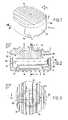
- FIG. 6is a partially cutaway view in perspective showing a second example of a prosthesis complying with the invention.
- FIG. 7is a front cutaway view taken in the sagittal plane of the prosthesis illustrated in FIG. 6 .
- FIG. 8is a top view of the prosthesis illustrated in FIG. 6 .
- FIG. 9is a front cutaway view taken roughly according to lines IX—IX—in FIG. 7 .
- Cervical prosthesis 1to be implanted in the place of a disk between two adjacent cervical vertebrae.
- Cervical prosthesis 1according to the invention comprises a first so-called upper plate 2 in the illustrated example and a second so-called lower plate 3 .
- Plates 2 and 3are intended to be fixed on neighbouring cervical vertebrae and each present an outer side, respectively 2 1 , 3 1 , of roughly similar dimensions adapted to take the exact shape of the associated articular surfaces.
- plates 2 and 3present an anatomic profile that can be adapted to the intervertebral space. Therefore, as indicated more specifically in FIG. 2 , the first plate 2 presents a convex profile in the sagittal plane S, while the second plate 3 presents a roughly flat profile in the same sagittal plane S. Moreover, as more specifically indicated in FIG. 4 , the second plate 3 has a convex profile in the front plane F, while the first plate 2 has a flat profile.
- outer sides 2 1 , 3 1 of plates 2 and 3are equipped with bone anchoring elements 4 in the vertebrae. In the example illustrated in FIG. 1 to 3 , outer sides 2 1 and 3 1 comprise parallel notches as anchoring elements 4 between themselves and the front plane F.
- each plate 2 , 3presents a general trapezoid form by having a posterior edge respectively 2 a , 3 a extending to the opposite side and parallel to front plane F and to an anterior edge 2 b , 3 b respectively.
- the anterior edge 2 b , 3 b of each plate 2 , 3is connected to the respective posterior edges 2 a , 3 a by means of two lateral edges 2 c , 3 c diverging from the anterior edge 2 b , 3 b .
- each lateral edge 2 c , 3 cis connected to the respective anterior edge 2 b , 3 b by a connection fillet 2 d , 3 d as well as to the posterior edge 2 a , 3 a by means of a connection fillet 2 e , 3 e
- means of articulation 7are inserted between the two plates 2 , 3 placed in a superimposed position.
- the means of articulation 7consist of:
- the means of articulation 7enable control of the relative movements in the front plane F, in the sagittal plane S and in the cross plane T between the first 2 and second 3 plates according to limited movements corresponding to the natural physiological mobility between two cervical vertebrae.
- the means of articulation 7allow that the plates can have movements according to the different combinations of these different planes.
- the means of articulation 7in particular, consist of a hole with a partially spherical profile 20 , established inside a chamber 21 prepared in the illustrated example in the second plate 3 .
- This holeis intended to co-operate with a bearing surface 23 with a profile complementary to hole 20 .
- the bearing surface 23 with the partially spherical profileis assembled in hole 20 so as to be locked together.
- Bearing surface 23is prepared in a first insert 25 assembled on the inner side of the first plate 2 and made in the form of a stub.
- insert 25includes a base with a circular cross-section partially inserted in a recess opening on to the inner side of plate 2 . This base extends by bearing surface 23 with a partially spherical profile.
- Hole 20is prepared in a second insert 26 assembled in chamber 21 of the second plate 3 and made in the shape of a ring. Inserts 25 , 26 are made of metal or ceramic.
- Hole 20 and bearing surface 23are means authorising flexion-extension movements in the sagittal plane S, lateral inflexion movements in the front plane F, and relative rotation movements in the cross plane T.
- the means of assembly 17 between the first and second plates 2 , 3are achieved by the insertion of the bearing surface 23 with a spherical profile in hole 20 .
- the means of articulation 7comprise an axis 31 crossing the bearing surface 23 from one end to the other by extending in the sagittal plane S.
- Axis 31protrudes on both sides of the bearing surface 23 by being engaged in the clearances 32 formed in the ring 26 by opening up in hole 20 .
- the two clearances 32that extend in a diametrically opposite way present a height, that is, a measurement in the sagittal plan S adapted to allow for flexion-extension movements in the sagittal plane of plate 2 relative to plate 3 .
- the means of stop in flexion-extensionare formed by the profile of plates 2 , 3 , coming into contact with each other.
- clearances 32has a determined diameter, that is, a measurement in the cross plane T determined to define the angular clearance of relative rotation movements between plates 2 , 3 .
- clearances 32limit the rotation of the axis 31 according to the cross plane T. Clearances 32 thereby form means of stop in relative rotation between plates 2 , 3 .
- axis 31allows for lateral inflexion movements in the front plane F perpendicular to sagittal plane S, of plate 2 relative to plate 3 .
- the means of stop 12 in lateral inflexionare formed by the profile of plates coming into contact with each other. Thereby, plates 2 , 3 come into contact with each other according to lateral inflexion movements according to their inner side respectively 2 2 and 3 2 extending opposite each other.
- FIGS. 6 to 9illustrate a second variant of the prosthesis 1 complying with the invention.
- This prosthesishas means of articulation 7 identical to those described above and for this reason comprises the same references.
- bearing surface 20is part of a ring 38 presenting a slot 39 allowing for the assembly of a bearing surface 23 by elastic deformation.
- the means of stop in relative rotationare formed by a female geometric shape 40 co-operating with a complementary male geometric shape 41 .
- One of the geometric shapesis prepared on a plate while the other geometric shape is prepared on the other plate.
- the female geometric shapeis prepared on insert 25 assembled in one piece with the first plate 2 while the complementary male geometric shape 41 extends from the back of the chamber 21 of the second plate 3 .
- These female 40 and male 41 geometric shapesare said to be complementary in that they authorise flexion-extension movements in the sagittal plane S, lateral inflexion movements in the front plane F, and relative rotation movements between the first and second plates.
- These geometric shapes 40 and 41are adapted to form means of stop in relative rotation between plates 2 and 3 for a limited angular clearance.
- the means of stop in flexion-extensionare formed by the inner sides 2 2 , 3 2 of the plates as more specifically indicated in FIG. 7 .
- the means of stop in lateral inflexion 12are formed by the inner sides respectively 2 2 and 3 2 of plates 2 , 3 as indicated clearly in FIG. 9 .
Landscapes
- Health & Medical Sciences (AREA)
- Engineering & Computer Science (AREA)
- Biomedical Technology (AREA)
- Neurology (AREA)
- Orthopedic Medicine & Surgery (AREA)
- Cardiology (AREA)
- Oral & Maxillofacial Surgery (AREA)
- Transplantation (AREA)
- Heart & Thoracic Surgery (AREA)
- Vascular Medicine (AREA)
- Life Sciences & Earth Sciences (AREA)
- Animal Behavior & Ethology (AREA)
- General Health & Medical Sciences (AREA)
- Public Health (AREA)
- Veterinary Medicine (AREA)
- Prostheses (AREA)
Abstract
Description
- a first and second plate intended to be fixed on neighbouring cervical vertebrae,
- and means of articulation inserted between the two plates placed in a superimposed position.
- means authorising flexion-extension movements in the sagittal plane according to an angular clearance limited by stop means in flexion-extension,
- means authorising lateral inflexion movements in a plane perpendicular to the sagittal plane according to an angular clearance limited by stop means in lateral inflexion,
- means authorising relative rotation movements between the first and second plates according to an angular clearance limited by stop means in relative rotation,
- means of assembly with the first and second plates so as to form a prosthesis consisting of a single piece.
- a hole with a partially spherical profile established inside a chamber prepared in a plate,
- and a bearing surface with a profile complementary to the hole prepared in the other plate and assembled in the hole to be locked in the latter.
- means authorising flexion-extension movements in the sagittal plane S according to an angular clearance limited by the means of stop in flexion-
extension 9, - means authorising lateral inflexion movements in a front plane F perpendicular to sagittal plane S according to an angular clearance limited by the means of stop in
lateral inflexion 12, - means authorising relative rotation movements between the first2 and second3 plates according to an angular clearance limited by the means of stop in relative rotation,
- means of
assembly 17 with the first2 and the second3 plates so as to form a prosthesis consisting of a single piece.
- means authorising flexion-extension movements in the sagittal plane S according to an angular clearance limited by the means of stop in flexion-
Claims (9)
Applications Claiming Priority (2)
| Application Number | Priority Date | Filing Date | Title |
|---|---|---|---|
| FR0307726 | 2003-06-26 | ||
| FR0307726AFR2856587B1 (en) | 2003-06-26 | 2003-06-26 | DISCRETE PROSTHESIS FOR CERVICAL VERTEBRATES WITH CONTROLLED DEBATMENT |
Publications (2)
| Publication Number | Publication Date |
|---|---|
| US20040267364A1 US20040267364A1 (en) | 2004-12-30 |
| US7060099B2true US7060099B2 (en) | 2006-06-13 |
Family
ID=33515430
Family Applications (1)
| Application Number | Title | Priority Date | Filing Date |
|---|---|---|---|
| US10/673,165Expired - LifetimeUS7060099B2 (en) | 2003-06-26 | 2003-09-30 | Disk prosthesis for cervical vertebrae with controlled clearance |
Country Status (6)
| Country | Link |
|---|---|
| US (1) | US7060099B2 (en) |
| EP (1) | EP1635745A1 (en) |
| JP (1) | JP4685771B2 (en) |
| BR (1) | BRPI0411768B1 (en) |
| FR (1) | FR2856587B1 (en) |
| WO (1) | WO2005000170A1 (en) |
Cited By (44)
| Publication number | Priority date | Publication date | Assignee | Title |
|---|---|---|---|---|
| US20040034422A1 (en)* | 2001-07-16 | 2004-02-19 | Errico Joseph P. | Intervertebral spacer device having a circumferentially buried wire mesh endplate attachment device |
| US20040153158A1 (en)* | 2001-07-16 | 2004-08-05 | Errico Joseph P. | Intervertebral spacer device having an angled perimeter for manipulation using a surgical tool |
| US20040167536A1 (en)* | 2001-07-16 | 2004-08-26 | Errico Joseph P. | Instrumentation for properly seating an artificial intervertebral disc in an intervertebral space |
| US20060004453A1 (en)* | 2004-06-30 | 2006-01-05 | Depuy Spine, Inc. | Ceramic disc prosthesis |
| US20070073404A1 (en)* | 2005-09-23 | 2007-03-29 | Ralph Rashbaum | Intervertebral disc prosthesis |
| US20070088441A1 (en)* | 2004-06-30 | 2007-04-19 | Synergy Disc Replacement, Inc. | Artificial Spinal Disc |
| US20070123906A1 (en)* | 2001-07-16 | 2007-05-31 | Spinecore, Inc. | Inserter/impactor for implanting an artificial intervertebral disc |
| US20070156243A1 (en)* | 2001-07-16 | 2007-07-05 | Spinecore, Inc. | Intervertebral spacer device having engagement hole pairs |
| US20070162139A1 (en)* | 2001-07-16 | 2007-07-12 | Ralph James D | Trial intervertebral distraction spacers |
| US20080133013A1 (en)* | 2004-06-30 | 2008-06-05 | Synergy Disc Replacement, Inc. | Artificial Spinal Disc |
| US20080183294A1 (en)* | 2005-04-19 | 2008-07-31 | Ali Adl | Hinged Artificial Spinal Disk Drive |
| US20080215156A1 (en)* | 2004-06-30 | 2008-09-04 | Synergy Disc Replacement | Joint Prostheses |
| US20080319548A1 (en)* | 2007-06-22 | 2008-12-25 | Axiomed Spine Corporation | Artificial disc |
| US20090076616A1 (en)* | 2004-06-30 | 2009-03-19 | Synergy Disc | Systems and Methods for Vertebral Disc Replacement |
| US20090270870A1 (en)* | 2008-04-24 | 2009-10-29 | Rafail Zubok | Dynamic distractor |
| US20090312765A1 (en)* | 2001-07-16 | 2009-12-17 | Spinecore, Inc. | Wedge Ramp Distractor for use in Implanting Artificial Intervertebral Discs |
| US20100016970A1 (en)* | 2008-07-17 | 2010-01-21 | John Kapitan | Spinal interbody spacers |
| US7695516B2 (en) | 2004-12-22 | 2010-04-13 | Ldr Medical | Intervertebral disc prosthesis |
| US20100161064A1 (en)* | 2006-11-07 | 2010-06-24 | Kellar Franz W | Prosthetic joint |
| US20100262250A1 (en)* | 2006-11-07 | 2010-10-14 | Kellar Franz W | Prosthetic ball-and-socket joint |
| US20100324686A1 (en)* | 2009-06-17 | 2010-12-23 | Gerner Leonie | Implant |
| US20110046744A1 (en)* | 2001-07-16 | 2011-02-24 | Spinecore, Inc. | Intervertebral spacer device having recessed notch pairs for manipulation using a surgical tool |
| US8002835B2 (en) | 2004-04-28 | 2011-08-23 | Ldr Medical | Intervertebral disc prosthesis |
| US8029574B2 (en) | 2006-11-07 | 2011-10-04 | Biomedflex Llc | Prosthetic knee joint |
| US8029568B2 (en) | 2001-10-18 | 2011-10-04 | Spinecore, Inc. | Intervertebral spacer device having a slotted partial circular domed arch strip spring |
| US8070823B2 (en) | 2006-11-07 | 2011-12-06 | Biomedflex Llc | Prosthetic ball-and-socket joint |
| US8083796B1 (en)* | 2008-02-29 | 2011-12-27 | Nuvasive, Inc. | Implants and methods for spinal fusion |
| US8092539B2 (en) | 2001-10-01 | 2012-01-10 | Spinecore, Inc. | Intervertebral spacer device having a belleville washer with concentric grooves |
| US8267999B2 (en) | 2002-11-05 | 2012-09-18 | Ldr Medical | Intervertebral disc prosthesis |
| US8308812B2 (en) | 2006-11-07 | 2012-11-13 | Biomedflex, Llc | Prosthetic joint assembly and joint member therefor |
| US8343219B2 (en) | 2007-06-08 | 2013-01-01 | Ldr Medical | Intersomatic cage, intervertebral prosthesis, anchoring device and implantation instruments |
| US8439931B2 (en) | 2005-06-29 | 2013-05-14 | Ldr Medical | Instrumentation and methods for inserting an intervertebral disc prosthesis |
| US8465546B2 (en) | 2007-02-16 | 2013-06-18 | Ldr Medical | Intervertebral disc prosthesis insertion assemblies |
| US8512413B2 (en) | 2006-11-07 | 2013-08-20 | Biomedflex, Llc | Prosthetic knee joint |
| US8858635B2 (en) | 2004-02-04 | 2014-10-14 | Ldr Medical | Intervertebral disc prosthesis |
| US9005306B2 (en) | 2006-11-07 | 2015-04-14 | Biomedflex, Llc | Medical Implants With Compliant Wear-Resistant Surfaces |
| US9005307B2 (en) | 2006-11-07 | 2015-04-14 | Biomedflex, Llc | Prosthetic ball-and-socket joint |
| US20150173912A1 (en)* | 2011-02-23 | 2015-06-25 | Globus Medical, Inc. | Six degree spine stabilization devices and methods |
| US9265618B2 (en) | 2005-11-30 | 2016-02-23 | Ldr Medical | Intervertebral disc prosthesis and instrumentation for insertion of the prosthesis between the vertebrae |
| US9333095B2 (en) | 2001-05-04 | 2016-05-10 | Ldr Medical | Intervertebral disc prosthesis, surgical methods, and fitting tools |
| US9566157B2 (en) | 2006-11-07 | 2017-02-14 | Biomedflex, Llc | Three-member prosthetic joint |
| US10603185B2 (en) | 2004-02-04 | 2020-03-31 | Ldr Medical | Intervertebral disc prosthesis |
| US11452618B2 (en) | 2019-09-23 | 2022-09-27 | Dimicron, Inc | Spinal artificial disc removal tool |
| US11540925B2 (en)* | 2016-12-19 | 2023-01-03 | Ngmedical Gmbh | Intervertebral disk prosthesis and method for producing an intervertebral disk prosthesis |
Families Citing this family (31)
| Publication number | Priority date | Publication date | Assignee | Title |
|---|---|---|---|---|
| DE202004021289U1 (en) | 2003-05-14 | 2007-06-06 | Kraus, Kilian | Height-adjustable implant for insertion between vertebral bodies and handling tool |
| US7909869B2 (en) | 2003-08-05 | 2011-03-22 | Flexuspine, Inc. | Artificial spinal unit assemblies |
| US7204853B2 (en) | 2003-08-05 | 2007-04-17 | Flexuspine, Inc. | Artificial functional spinal unit assemblies |
| US7799082B2 (en) | 2003-08-05 | 2010-09-21 | Flexuspine, Inc. | Artificial functional spinal unit system and method for use |
| US7753958B2 (en) | 2003-08-05 | 2010-07-13 | Gordon Charles R | Expandable intervertebral implant |
| US7316714B2 (en) | 2003-08-05 | 2008-01-08 | Flexuspine, Inc. | Artificial functional spinal unit assemblies |
| DE10357926B3 (en) | 2003-12-11 | 2005-09-01 | Deltacor Gmbh | Length adjustable spinal implant |
| US20060041314A1 (en)* | 2004-08-20 | 2006-02-23 | Thierry Millard | Artificial disc prosthesis |
| AU2005314224B2 (en)* | 2004-12-06 | 2009-10-08 | Axiomed Spine Corporation | Method for replacing a spinal disc |
| US8182536B2 (en)* | 2006-02-01 | 2012-05-22 | Synthes Usa, Llc | Total disc replacement device |
| KR101337707B1 (en)* | 2006-02-23 | 2013-12-06 | 퍼네윌 이노베이션스 인베스트먼트 엘티디. | Intervertebral disc replacement |
| US8118869B2 (en) | 2006-03-08 | 2012-02-21 | Flexuspine, Inc. | Dynamic interbody device |
| US8920502B1 (en)* | 2006-11-08 | 2014-12-30 | Spinal Usa, Inc. | Vertebral body replacement |
| US9023107B2 (en)* | 2006-11-08 | 2015-05-05 | Spinal Usa, Inc. | Vertebral body replacement |
| FR2909859B1 (en)* | 2006-12-13 | 2011-02-11 | Lionel Francois Simon | JOINT PROSTHESIS OF INTERVERTEBRAL DISC |
| US7959677B2 (en) | 2007-01-19 | 2011-06-14 | Flexuspine, Inc. | Artificial functional spinal unit system and method for use |
| US8182514B2 (en) | 2007-10-22 | 2012-05-22 | Flexuspine, Inc. | Dampener system for a posterior stabilization system with a fixed length elongated member |
| US8157844B2 (en) | 2007-10-22 | 2012-04-17 | Flexuspine, Inc. | Dampener system for a posterior stabilization system with a variable length elongated member |
| US8162994B2 (en) | 2007-10-22 | 2012-04-24 | Flexuspine, Inc. | Posterior stabilization system with isolated, dual dampener systems |
| US8523912B2 (en) | 2007-10-22 | 2013-09-03 | Flexuspine, Inc. | Posterior stabilization systems with shared, dual dampener systems |
| US8267965B2 (en) | 2007-10-22 | 2012-09-18 | Flexuspine, Inc. | Spinal stabilization systems with dynamic interbody devices |
| US8187330B2 (en) | 2007-10-22 | 2012-05-29 | Flexuspine, Inc. | Dampener system for a posterior stabilization system with a variable length elongated member |
| MX2009013147A (en)* | 2009-06-17 | 2011-05-04 | Ulrich Gmbh & Co Kg | Implant. |
| US20110015743A1 (en)* | 2009-07-14 | 2011-01-20 | Doctors Research Group, Inc. | Multi-density polymeric interbody spacer |
| US20110012280A1 (en)* | 2009-07-14 | 2011-01-20 | Doctors Research Group, Inc. | Method for fabricating a multi-density polymeric interbody spacer |
| US8388687B2 (en) | 2011-03-25 | 2013-03-05 | Flexuspine, Inc. | Interbody device insertion systems and methods |
| US9526627B2 (en) | 2011-11-17 | 2016-12-27 | Exactech, Inc. | Expandable interbody device system and method |
| US9492288B2 (en) | 2013-02-20 | 2016-11-15 | Flexuspine, Inc. | Expandable fusion device for positioning between adjacent vertebral bodies |
| US10398565B2 (en) | 2014-04-24 | 2019-09-03 | Choice Spine, Llc | Limited profile intervertebral implant with incorporated fastening and locking mechanism |
| US9517144B2 (en) | 2014-04-24 | 2016-12-13 | Exactech, Inc. | Limited profile intervertebral implant with incorporated fastening mechanism |
| CN108836580A (en)* | 2018-07-06 | 2018-11-20 | 北京爱康宜诚医疗器材有限公司 | Artificial intervertebral disk frame body |
Citations (10)
| Publication number | Priority date | Publication date | Assignee | Title |
|---|---|---|---|---|
| US4759769A (en)* | 1987-02-12 | 1988-07-26 | Health & Research Services Inc. | Artificial spinal disc |
| US5314477A (en)* | 1990-03-07 | 1994-05-24 | J.B.S. Limited Company | Prosthesis for intervertebral discs and instruments for implanting it |
| US5401269A (en)* | 1992-03-13 | 1995-03-28 | Waldemar Link Gmbh & Co. | Intervertebral disc endoprosthesis |
| US5562738A (en)* | 1992-01-06 | 1996-10-08 | Danek Medical, Inc. | Intervertebral disk arthroplasty device |
| US5676701A (en)* | 1993-01-14 | 1997-10-14 | Smith & Nephew, Inc. | Low wear artificial spinal disc |
| US5895428A (en)* | 1996-11-01 | 1999-04-20 | Berry; Don | Load bearing spinal joint implant |
| US5899941A (en)* | 1997-12-09 | 1999-05-04 | Chubu Bearing Kabushiki Kaisha | Artificial intervertebral disk |
| US6368350B1 (en)* | 1999-03-11 | 2002-04-09 | Sulzer Spine-Tech Inc. | Intervertebral disc prosthesis and method |
| US6517580B1 (en)* | 2000-03-03 | 2003-02-11 | Scient'x Societe A Responsabilite Limited | Disk prosthesis for cervical vertebrae |
| US6679915B1 (en)* | 1998-04-23 | 2004-01-20 | Sdgi Holdings, Inc. | Articulating spinal implant |
Family Cites Families (5)
| Publication number | Priority date | Publication date | Assignee | Title |
|---|---|---|---|---|
| US5258031A (en)* | 1992-01-06 | 1993-11-02 | Danek Medical | Intervertebral disk arthroplasty |
| US5683465A (en)* | 1996-03-18 | 1997-11-04 | Shinn; Gary Lee | Artificial intervertebral disk prosthesis |
| US6063121A (en)* | 1998-07-29 | 2000-05-16 | Xavier; Ravi | Vertebral body prosthesis |
| US7160327B2 (en)* | 2001-07-16 | 2007-01-09 | Spinecore, Inc. | Axially compressible artificial intervertebral disc having limited rotation using a captured ball and socket joint with a solid ball and compression locking post |
| CA2461407A1 (en)* | 2001-09-28 | 2003-04-03 | Sulzer Spine-Tech Inc. | Skeletal stabilization implant |
- 2003
- 2003-06-26FRFR0307726Apatent/FR2856587B1/ennot_activeExpired - Fee Related
- 2003-09-30USUS10/673,165patent/US7060099B2/ennot_activeExpired - Lifetime
- 2004
- 2004-06-25EPEP04767462Apatent/EP1635745A1/ennot_activeWithdrawn
- 2004-06-25BRBRPI0411768Apatent/BRPI0411768B1/ennot_activeIP Right Cessation
- 2004-06-25JPJP2006516325Apatent/JP4685771B2/ennot_activeExpired - Fee Related
- 2004-06-25WOPCT/FR2004/001614patent/WO2005000170A1/enactiveApplication Filing
Patent Citations (10)
| Publication number | Priority date | Publication date | Assignee | Title |
|---|---|---|---|---|
| US4759769A (en)* | 1987-02-12 | 1988-07-26 | Health & Research Services Inc. | Artificial spinal disc |
| US5314477A (en)* | 1990-03-07 | 1994-05-24 | J.B.S. Limited Company | Prosthesis for intervertebral discs and instruments for implanting it |
| US5562738A (en)* | 1992-01-06 | 1996-10-08 | Danek Medical, Inc. | Intervertebral disk arthroplasty device |
| US5401269A (en)* | 1992-03-13 | 1995-03-28 | Waldemar Link Gmbh & Co. | Intervertebral disc endoprosthesis |
| US5676701A (en)* | 1993-01-14 | 1997-10-14 | Smith & Nephew, Inc. | Low wear artificial spinal disc |
| US5895428A (en)* | 1996-11-01 | 1999-04-20 | Berry; Don | Load bearing spinal joint implant |
| US5899941A (en)* | 1997-12-09 | 1999-05-04 | Chubu Bearing Kabushiki Kaisha | Artificial intervertebral disk |
| US6679915B1 (en)* | 1998-04-23 | 2004-01-20 | Sdgi Holdings, Inc. | Articulating spinal implant |
| US6368350B1 (en)* | 1999-03-11 | 2002-04-09 | Sulzer Spine-Tech Inc. | Intervertebral disc prosthesis and method |
| US6517580B1 (en)* | 2000-03-03 | 2003-02-11 | Scient'x Societe A Responsabilite Limited | Disk prosthesis for cervical vertebrae |
Cited By (105)
| Publication number | Priority date | Publication date | Assignee | Title |
|---|---|---|---|---|
| US8858564B2 (en) | 2001-02-15 | 2014-10-14 | Spinecore, Inc. | Wedge plate inserter/impactor and related methods for use in implanting an artificial intervertebral disc |
| US8940047B2 (en) | 2001-02-15 | 2015-01-27 | Spinecore, Inc. | Intervertebral spacer device having recessed notch pairs for manipulation using a surgical tool |
| US9333095B2 (en) | 2001-05-04 | 2016-05-10 | Ldr Medical | Intervertebral disc prosthesis, surgical methods, and fitting tools |
| US8545564B2 (en) | 2001-07-16 | 2013-10-01 | Spinecore, Inc. | Intervertebral spacer device having an articulation member and housing |
| US8608752B2 (en) | 2001-07-16 | 2013-12-17 | Spinecore, Inc. | Trial intervertebral distraction spacers |
| US8636804B2 (en) | 2001-07-16 | 2014-01-28 | Spinecore, Inc. | Instrumentation for properly seating an artificial intervertebral disc in an intervertebral space |
| US20070123906A1 (en)* | 2001-07-16 | 2007-05-31 | Spinecore, Inc. | Inserter/impactor for implanting an artificial intervertebral disc |
| US20070156243A1 (en)* | 2001-07-16 | 2007-07-05 | Spinecore, Inc. | Intervertebral spacer device having engagement hole pairs |
| US20070162139A1 (en)* | 2001-07-16 | 2007-07-12 | Ralph James D | Trial intervertebral distraction spacers |
| US8366775B2 (en) | 2001-07-16 | 2013-02-05 | Spinecore, Inc. | Intervertebral spacer device having an angled perimeter for manipulation using a surgical tool |
| US8357167B2 (en) | 2001-07-16 | 2013-01-22 | Spinecore, Inc. | Artificial intervertebral disc trials with baseplates having inward tool engagement holes |
| US8758358B2 (en) | 2001-07-16 | 2014-06-24 | Spinecore, Inc. | Instrumentation for repositioning and extraction an artificial intervertebral disc from an intervertebral space |
| US8303659B2 (en) | 2001-07-16 | 2012-11-06 | Spinecore, Inc. | Intervertebral spacer device having engagement hole pairs |
| US9132020B2 (en) | 2001-07-16 | 2015-09-15 | Spinecore, Inc. | Wedge ramp distractor for use in implanting artificial intervertebral discs |
| US20040153158A1 (en)* | 2001-07-16 | 2004-08-05 | Errico Joseph P. | Intervertebral spacer device having an angled perimeter for manipulation using a surgical tool |
| US8216315B2 (en) | 2001-07-16 | 2012-07-10 | Spinecore, Inc. | Trial intervertebral distraction spacers |
| US20110046744A1 (en)* | 2001-07-16 | 2011-02-24 | Spinecore, Inc. | Intervertebral spacer device having recessed notch pairs for manipulation using a surgical tool |
| US9700429B2 (en) | 2001-07-16 | 2017-07-11 | Spinecore, Inc. | Intervertebral spacer device having recessed notch pairs for manipulation using a surgical tool |
| US20090312765A1 (en)* | 2001-07-16 | 2009-12-17 | Spinecore, Inc. | Wedge Ramp Distractor for use in Implanting Artificial Intervertebral Discs |
| US20090326542A9 (en)* | 2001-07-16 | 2009-12-31 | Errico Joseph P | Instrumentation for properly seating an artificial intervertebral disc in an intervertebral space |
| US20040034422A1 (en)* | 2001-07-16 | 2004-02-19 | Errico Joseph P. | Intervertebral spacer device having a circumferentially buried wire mesh endplate attachment device |
| US9814596B2 (en) | 2001-07-16 | 2017-11-14 | Spinecore, Inc. | Method of orienting an intervertebral spacer device having recessed notch pairs by using a surgical tool |
| US20040167536A1 (en)* | 2001-07-16 | 2004-08-26 | Errico Joseph P. | Instrumentation for properly seating an artificial intervertebral disc in an intervertebral space |
| US8092539B2 (en) | 2001-10-01 | 2012-01-10 | Spinecore, Inc. | Intervertebral spacer device having a belleville washer with concentric grooves |
| US8029568B2 (en) | 2001-10-18 | 2011-10-04 | Spinecore, Inc. | Intervertebral spacer device having a slotted partial circular domed arch strip spring |
| US8267999B2 (en) | 2002-11-05 | 2012-09-18 | Ldr Medical | Intervertebral disc prosthesis |
| US8858635B2 (en) | 2004-02-04 | 2014-10-14 | Ldr Medical | Intervertebral disc prosthesis |
| US10603185B2 (en) | 2004-02-04 | 2020-03-31 | Ldr Medical | Intervertebral disc prosthesis |
| US11957598B2 (en) | 2004-02-04 | 2024-04-16 | Ldr Medical | Intervertebral disc prosthesis |
| US8002835B2 (en) | 2004-04-28 | 2011-08-23 | Ldr Medical | Intervertebral disc prosthesis |
| US20090043393A1 (en)* | 2004-06-30 | 2009-02-12 | Synergy Disc Replacement, Inc. | Artificial Spinal Disc |
| US8894709B2 (en) | 2004-06-30 | 2014-11-25 | Synergy Disc Replacement, Inc. | Systems and methods for vertebral disc replacement |
| US20110082556A1 (en)* | 2004-06-30 | 2011-04-07 | Synergy Disc Replacement, Inc. | Artificial Spinal Disc |
| US8021428B2 (en) | 2004-06-30 | 2011-09-20 | Depuy Spine, Inc. | Ceramic disc prosthesis |
| US9237958B2 (en) | 2004-06-30 | 2016-01-19 | Synergy Disc Replacement Inc. | Joint prostheses |
| US10064739B2 (en) | 2004-06-30 | 2018-09-04 | Synergy Disc Replacement, Inc. | Systems and methods for vertebral disc replacement |
| US8038716B2 (en) | 2004-06-30 | 2011-10-18 | Synergy Disc Replacement, Inc | Artificial spinal disc |
| US9125754B2 (en) | 2004-06-30 | 2015-09-08 | Synergy Disc Replacement, Inc. | Artificial spinal disc |
| US7927374B2 (en) | 2004-06-30 | 2011-04-19 | Synergy Disc Replacement, Inc. | Artificial spinal disc |
| US20060004453A1 (en)* | 2004-06-30 | 2006-01-05 | Depuy Spine, Inc. | Ceramic disc prosthesis |
| US8100974B2 (en) | 2004-06-30 | 2012-01-24 | Synergy Disc Replacement, Inc. | Artificial spinal disc |
| US20080133013A1 (en)* | 2004-06-30 | 2008-06-05 | Synergy Disc Replacement, Inc. | Artificial Spinal Disc |
| US8172904B2 (en) | 2004-06-30 | 2012-05-08 | Synergy Disc Replacement, Inc. | Artificial spinal disc |
| US20070088441A1 (en)* | 2004-06-30 | 2007-04-19 | Synergy Disc Replacement, Inc. | Artificial Spinal Disc |
| US20090076616A1 (en)* | 2004-06-30 | 2009-03-19 | Synergy Disc | Systems and Methods for Vertebral Disc Replacement |
| US20090069894A1 (en)* | 2004-06-30 | 2009-03-12 | Synergy Disc Replacement, Inc. | Artificial Spinal Disc |
| US8231677B2 (en) | 2004-06-30 | 2012-07-31 | Synergy Disc Replacement, Inc. | Artificial spinal disc |
| US8454699B2 (en) | 2004-06-30 | 2013-06-04 | Synergy Disc Replacement, Inc | Systems and methods for vertebral disc replacement |
| US20090043392A1 (en)* | 2004-06-30 | 2009-02-12 | Synergy Disc Replacement, Inc. | Artificial Spinal Disc |
| US10786362B2 (en) | 2004-06-30 | 2020-09-29 | Synergy Disc Replacement, Inc. | Systems and methods for vertebral disc replacement |
| US8852193B2 (en) | 2004-06-30 | 2014-10-07 | Synergy Disc Replacement, Inc. | Systems and methods for vertebral disc replacement |
| US20080215156A1 (en)* | 2004-06-30 | 2008-09-04 | Synergy Disc Replacement | Joint Prostheses |
| US10226355B2 (en) | 2004-12-22 | 2019-03-12 | Ldr Medical | Intervertebral disc prosthesis |
| US8257439B2 (en) | 2004-12-22 | 2012-09-04 | Ldr Medical | Intervertebral disc prosthesis |
| US7695516B2 (en) | 2004-12-22 | 2010-04-13 | Ldr Medical | Intervertebral disc prosthesis |
| US20080183294A1 (en)* | 2005-04-19 | 2008-07-31 | Ali Adl | Hinged Artificial Spinal Disk Drive |
| US8357200B2 (en)* | 2005-04-19 | 2013-01-22 | Ali Adl | Hinged artificial spinal disk device |
| US8439931B2 (en) | 2005-06-29 | 2013-05-14 | Ldr Medical | Instrumentation and methods for inserting an intervertebral disc prosthesis |
| US10350088B2 (en) | 2005-06-29 | 2019-07-16 | Ldr Medical | Instrumentation and methods for inserting an intervertebral disc prosthesis |
| US7842088B2 (en) | 2005-09-23 | 2010-11-30 | Ldr Medical | Intervertebral disc prosthesis |
| US11872138B2 (en) | 2005-09-23 | 2024-01-16 | Ldr Medical | Intervertebral disc prosthesis |
| US20070073404A1 (en)* | 2005-09-23 | 2007-03-29 | Ralph Rashbaum | Intervertebral disc prosthesis |
| US10492919B2 (en) | 2005-09-23 | 2019-12-03 | Ldr Medical | Intervertebral disc prosthesis |
| US9265618B2 (en) | 2005-11-30 | 2016-02-23 | Ldr Medical | Intervertebral disc prosthesis and instrumentation for insertion of the prosthesis between the vertebrae |
| US9005307B2 (en) | 2006-11-07 | 2015-04-14 | Biomedflex, Llc | Prosthetic ball-and-socket joint |
| US8029574B2 (en) | 2006-11-07 | 2011-10-04 | Biomedflex Llc | Prosthetic knee joint |
| US8308812B2 (en) | 2006-11-07 | 2012-11-13 | Biomedflex, Llc | Prosthetic joint assembly and joint member therefor |
| US20100280623A9 (en)* | 2006-11-07 | 2010-11-04 | Kellar Franz W | Prosthetic joint |
| US20100161064A1 (en)* | 2006-11-07 | 2010-06-24 | Kellar Franz W | Prosthetic joint |
| US9005306B2 (en) | 2006-11-07 | 2015-04-14 | Biomedflex, Llc | Medical Implants With Compliant Wear-Resistant Surfaces |
| US9566157B2 (en) | 2006-11-07 | 2017-02-14 | Biomedflex, Llc | Three-member prosthetic joint |
| US7905919B2 (en) | 2006-11-07 | 2011-03-15 | Biomedflex Llc | Prosthetic joint |
| US9107754B2 (en) | 2006-11-07 | 2015-08-18 | Biomedflex, Llc | Prosthetic joint assembly and prosthetic joint member |
| US8070823B2 (en) | 2006-11-07 | 2011-12-06 | Biomedflex Llc | Prosthetic ball-and-socket joint |
| US8512413B2 (en) | 2006-11-07 | 2013-08-20 | Biomedflex, Llc | Prosthetic knee joint |
| US20100262250A1 (en)* | 2006-11-07 | 2010-10-14 | Kellar Franz W | Prosthetic ball-and-socket joint |
| US7914580B2 (en) | 2006-11-07 | 2011-03-29 | Biomedflex Llc | Prosthetic ball-and-socket joint |
| US8465546B2 (en) | 2007-02-16 | 2013-06-18 | Ldr Medical | Intervertebral disc prosthesis insertion assemblies |
| US10188528B2 (en) | 2007-02-16 | 2019-01-29 | Ldr Medical | Interveterbral disc prosthesis insertion assemblies |
| US10398574B2 (en) | 2007-02-16 | 2019-09-03 | Ldr Medical | Intervertebral disc prosthesis insertion assemblies |
| US10751187B2 (en) | 2007-06-08 | 2020-08-25 | Ldr Medical | Intersomatic cage, intervertebral prosthesis, anchoring device and implantation instruments |
| US8343219B2 (en) | 2007-06-08 | 2013-01-01 | Ldr Medical | Intersomatic cage, intervertebral prosthesis, anchoring device and implantation instruments |
| US8956412B2 (en)* | 2007-06-22 | 2015-02-17 | Axiomed, LLC | Artificial disc |
| US20080319548A1 (en)* | 2007-06-22 | 2008-12-25 | Axiomed Spine Corporation | Artificial disc |
| US12016783B2 (en) | 2008-02-29 | 2024-06-25 | Nuvasive, Inc. | Implants and methods for spinal fusion |
| US9907672B1 (en) | 2008-02-29 | 2018-03-06 | Nuvasive, Inc. | Implants and methods for spinal fusion |
| US9168152B2 (en) | 2008-02-29 | 2015-10-27 | Nuvasive, Inc. | Implants and methods for spinal fusion |
| US10842646B2 (en) | 2008-02-29 | 2020-11-24 | Nuvasive, In.C | Implants and methods for spinal fusion |
| US8083796B1 (en)* | 2008-02-29 | 2011-12-27 | Nuvasive, Inc. | Implants and methods for spinal fusion |
| US20090270870A1 (en)* | 2008-04-24 | 2009-10-29 | Rafail Zubok | Dynamic distractor |
| US8147499B2 (en) | 2008-04-24 | 2012-04-03 | Spinecore, Inc. | Dynamic distractor |
| US8172902B2 (en) | 2008-07-17 | 2012-05-08 | Spinemedica, Llc | Spinal interbody spacers |
| US20100016970A1 (en)* | 2008-07-17 | 2010-01-21 | John Kapitan | Spinal interbody spacers |
| US8202321B2 (en)* | 2009-06-17 | 2012-06-19 | Ulrich Gmbh & Co. Kg | Implant |
| US20100324686A1 (en)* | 2009-06-17 | 2010-12-23 | Gerner Leonie | Implant |
| US11857433B2 (en)* | 2011-02-23 | 2024-01-02 | Globus Medical, Inc. | Six degree spine stabilization devices and methods |
| US11357639B2 (en)* | 2011-02-23 | 2022-06-14 | Globus Medical, Inc. | Six degree spine stabilization devices and methods |
| US20220273457A1 (en)* | 2011-02-23 | 2022-09-01 | Globus Medical, Inc. | Six degree spine stabilization devices and methods |
| US10687958B2 (en)* | 2011-02-23 | 2020-06-23 | Globus Medical, Inc. | Six degree spine stabilization devices and methods |
| US20150173912A1 (en)* | 2011-02-23 | 2015-06-25 | Globus Medical, Inc. | Six degree spine stabilization devices and methods |
| US10092411B2 (en)* | 2011-02-23 | 2018-10-09 | Globus Medical Inc | Six degree spine stabilization devices and methods |
| US9452060B2 (en)* | 2011-02-23 | 2016-09-27 | Globus Medical, Inc. | Six degree spine stabilization devices and methods |
| US11540925B2 (en)* | 2016-12-19 | 2023-01-03 | Ngmedical Gmbh | Intervertebral disk prosthesis and method for producing an intervertebral disk prosthesis |
| US11452618B2 (en) | 2019-09-23 | 2022-09-27 | Dimicron, Inc | Spinal artificial disc removal tool |
| US11590003B2 (en) | 2019-09-23 | 2023-02-28 | Dimicron Inc. | Spinal artificial disc removal tool |
Also Published As
| Publication number | Publication date |
|---|---|
| BRPI0411768B1 (en) | 2016-04-26 |
| FR2856587B1 (en) | 2006-02-24 |
| JP2007515978A (en) | 2007-06-21 |
| US20040267364A1 (en) | 2004-12-30 |
| BRPI0411768A (en) | 2006-08-08 |
| JP4685771B2 (en) | 2011-05-18 |
| FR2856587A1 (en) | 2004-12-31 |
| WO2005000170A1 (en) | 2005-01-06 |
| EP1635745A1 (en) | 2006-03-22 |
Similar Documents
| Publication | Publication Date | Title |
|---|---|---|
| US7060099B2 (en) | Disk prosthesis for cervical vertebrae with controlled clearance | |
| US7083651B2 (en) | Spinal implant | |
| USRE40260E1 (en) | Disk prosthesis for cervical vertebrae | |
| EP1983945B1 (en) | Modular intervertebral disc replacements | |
| US8100974B2 (en) | Artificial spinal disc | |
| EP2764852B1 (en) | Orthopaedic medical device | |
| US8337561B2 (en) | Spinal disc prosthesis system | |
| US20050149189A1 (en) | Intervertebral disk prosthesis | |
| US8915964B2 (en) | Flexible dampening intervertebral spacer device | |
| EP2633835A2 (en) | Bandscheibenprothese | |
| US20070021837A1 (en) | Stabilizing augment for prosthetic disc | |
| US20040127991A1 (en) | Biaxial artificial disc replacement | |
| US9937051B2 (en) | Artificial disc devices and related methods of use | |
| US20060235528A1 (en) | Angled sliding core, also as part of an intervertebral disc prosthesis, for the lumbar and cervical spine | |
| US11083590B2 (en) | Intersomatic prosthesis with lateral introduction | |
| US20150289986A1 (en) | Flanged endplate for an intervertebral disc prosthesis and intervertebral disc prosthesis incorporating same |
Legal Events
| Date | Code | Title | Description |
|---|---|---|---|
| AS | Assignment | Owner name:SCIENT'X, FRANCE Free format text:ASSIGNMENT OF ASSIGNORS INTEREST;ASSIGNORS:CARLI, OLIVIER;BEN-MOKHTAR, MOURAD;REEL/FRAME:014555/0776 Effective date:20030910 | |
| STCF | Information on status: patent grant | Free format text:PATENTED CASE | |
| FEPP | Fee payment procedure | Free format text:PAT HOLDER NO LONGER CLAIMS SMALL ENTITY STATUS, ENTITY STATUS SET TO UNDISCOUNTED (ORIGINAL EVENT CODE: STOL); ENTITY STATUS OF PATENT OWNER: LARGE ENTITY | |
| AS | Assignment | Owner name:OXFORD FINANCE CORPORATION, VIRGINIA Free format text:SECURITY AGREEMENT;ASSIGNOR:SCIENT'X, S.A.;REEL/FRAME:022824/0197 Effective date:20090529 | |
| FPAY | Fee payment | Year of fee payment:4 | |
| FPAY | Fee payment | Year of fee payment:8 | |
| AS | Assignment | Owner name:DEERFIELD PRIVATE DESIGN FUND II, L.P., NEW YORK Free format text:SECURITY INTEREST;ASSIGNORS:ALPHATEC HOLDINGS, INC.;ALPHATEC SPINE, INC.;ALPHATEC INTERNATIONAL LLC;AND OTHERS;REEL/FRAME:032551/0037 Effective date:20140317 Owner name:DEERFIELD PRIVATE DESIGN INTERNATIONAL II, L.P., N Free format text:SECURITY INTEREST;ASSIGNORS:ALPHATEC HOLDINGS, INC.;ALPHATEC SPINE, INC.;ALPHATEC INTERNATIONAL LLC;AND OTHERS;REEL/FRAME:032551/0037 Effective date:20140317 Owner name:DEERFIELD SPECIAL SITUATIONS INTERNATIONAL MASTER Free format text:SECURITY INTEREST;ASSIGNORS:ALPHATEC HOLDINGS, INC.;ALPHATEC SPINE, INC.;ALPHATEC INTERNATIONAL LLC;AND OTHERS;REEL/FRAME:032551/0037 Effective date:20140317 Owner name:DEERFIELD SPECIAL SITUATIONS FUND, L.P., NEW YORK Free format text:SECURITY INTEREST;ASSIGNORS:ALPHATEC HOLDINGS, INC.;ALPHATEC SPINE, INC.;ALPHATEC INTERNATIONAL LLC;AND OTHERS;REEL/FRAME:032551/0037 Effective date:20140317 | |
| AS | Assignment | Owner name:ALPHATEC SPINE, INC., CALIFORNIA Free format text:RELEASE BY SECURED PARTY;ASSIGNORS:DEERFIELD PRIVATE DESIGN FUND II, L.P.;DEERFIELD PRIVATE DESIGN INTERNATIONAL II, L.P.;DEERFIELD SPECIAL SITUATIONS FUND, L.P.;AND OTHERS;REEL/FRAME:039950/0360 Effective date:20160901 Owner name:ALPHATEC PACIFIC, INC., CALIFORNIA Free format text:RELEASE BY SECURED PARTY;ASSIGNORS:DEERFIELD PRIVATE DESIGN FUND II, L.P.;DEERFIELD PRIVATE DESIGN INTERNATIONAL II, L.P.;DEERFIELD SPECIAL SITUATIONS FUND, L.P.;AND OTHERS;REEL/FRAME:039950/0360 Effective date:20160901 Owner name:ALPHATEC HOLDINGS, INC., CALIFORNIA Free format text:RELEASE BY SECURED PARTY;ASSIGNORS:DEERFIELD PRIVATE DESIGN FUND II, L.P.;DEERFIELD PRIVATE DESIGN INTERNATIONAL II, L.P.;DEERFIELD SPECIAL SITUATIONS FUND, L.P.;AND OTHERS;REEL/FRAME:039950/0360 Effective date:20160901 Owner name:ALPHATEC INTERNATIONAL LLC, CALIFORNIA Free format text:RELEASE BY SECURED PARTY;ASSIGNORS:DEERFIELD PRIVATE DESIGN FUND II, L.P.;DEERFIELD PRIVATE DESIGN INTERNATIONAL II, L.P.;DEERFIELD SPECIAL SITUATIONS FUND, L.P.;AND OTHERS;REEL/FRAME:039950/0360 Effective date:20160901 | |
| AS | Assignment | Owner name:GLOBUS MEDICAL, INC., PENNSYLVANIA Free format text:INTELLECTUAL PROPERTY SECURITY AGREEMENT;ASSIGNORS:ALPHATEC HOLDINGS, INC.;ALPHATEC SPINE, INC.;REEL/FRAME:040108/0202 Effective date:20160901 | |
| MAFP | Maintenance fee payment | Free format text:PAYMENT OF MAINTENANCE FEE, 12TH YEAR, LARGE ENTITY (ORIGINAL EVENT CODE: M1553) Year of fee payment:12 | |
| AS | Assignment | Owner name:ALPHATEC SPINE, INC., CALIFORNIA Free format text:RELEASE BY SECURED PARTY;ASSIGNOR:GLOBUS MEDICAL, INC.;REEL/FRAME:047485/0084 Effective date:20181107 Owner name:ALPHATEC HOLDINGS, INC., CALIFORNIA Free format text:RELEASE BY SECURED PARTY;ASSIGNOR:GLOBUS MEDICAL, INC.;REEL/FRAME:047485/0084 Effective date:20181107 | |
| AS | Assignment | Owner name:SQUADRON MEDICAL FINANCE SOLUTIONS LLC, CONNECTICUT Free format text:SECURITY INTEREST;ASSIGNORS:ALPHATEC HOLDINGS, INC.;ALPHATEC SPINE, INC.;REEL/FRAME:047494/0562 Effective date:20181106 Owner name:SQUADRON MEDICAL FINANCE SOLUTIONS LLC, CONNECTICU Free format text:SECURITY INTEREST;ASSIGNORS:ALPHATEC HOLDINGS, INC.;ALPHATEC SPINE, INC.;REEL/FRAME:047494/0562 Effective date:20181106 | |
| AS | Assignment | Owner name:ALPHATEC SPINE, INC., CALIFORNIA Free format text:RELEASE BY SECURED PARTY;ASSIGNOR:MIDCAP FUNDING IV TRUST;REEL/FRAME:052832/0132 Effective date:20200529 Owner name:ALPHATEC HOLDINGS, INC., DELAWARE Free format text:RELEASE BY SECURED PARTY;ASSIGNOR:MIDCAP FUNDING IV TRUST;REEL/FRAME:052832/0132 Effective date:20200529 | |
| AS | Assignment | Owner name:ALPHATEC HOLDINGS, INC., CALIFORNIA Free format text:RELEASE OF SECURITY INTEREST IN PATENT COLLATERAL AT REEL/FRAME NO. 47494/0562;ASSIGNOR:SQUADRON MEDICAL FINANCE SOLUTIONS LLC;REEL/FRAME:057177/0687 Effective date:20210804 Owner name:ALPHATEC SPINE, INC., CALIFORNIA Free format text:RELEASE OF SECURITY INTEREST IN PATENT COLLATERAL AT REEL/FRAME NO. 47494/0562;ASSIGNOR:SQUADRON MEDICAL FINANCE SOLUTIONS LLC;REEL/FRAME:057177/0687 Effective date:20210804 | |
| AS | Assignment | Owner name:MIDCAP FUNDING IV TRUST, MARYLAND Free format text:SECURITY INTEREST;ASSIGNORS:ALPHATEC SPINE, INC.;SAFEOP SURGICAL, INC.;REEL/FRAME:062310/0001 Effective date:20230106 | |
| AS | Assignment | Owner name:WILMINGTON TRUST, NATIONAL ASSOCIATION, DELAWARE Free format text:SECURITY INTEREST;ASSIGNORS:ALPHATEC SPINE, INC.;SAFEOP SURGICAL, INC.;REEL/FRAME:062681/0020 Effective date:20230106 |