US7060089B2 - Multi-layer stent - Google Patents
Multi-layer stentDownload PDFInfo
- Publication number
- US7060089B2 US7060089B2US10/055,307US5530702AUS7060089B2US 7060089 B2US7060089 B2US 7060089B2US 5530702 AUS5530702 AUS 5530702AUS 7060089 B2US7060089 B2US 7060089B2
- Authority
- US
- United States
- Prior art keywords
- stent
- segment
- distance
- peaks
- segments
- Prior art date
- Legal status (The legal status is an assumption and is not a legal conclusion. Google has not performed a legal analysis and makes no representation as to the accuracy of the status listed.)
- Expired - Fee Related, expires
Links
- WYTGDNHDOZPMIW-RCBQFDQVSA-NalstonineNatural productsC1=CC2=C3C=CC=CC3=NC2=C2N1C[C@H]1[C@H](C)OC=C(C(=O)OC)[C@H]1C2WYTGDNHDOZPMIW-RCBQFDQVSA-N0.000claimsabstractdescription19
- 239000000463materialSubstances0.000description25
- 229910052751metalInorganic materials0.000description14
- 239000002184metalSubstances0.000description14
- 230000001419dependent effectEffects0.000description10
- 150000002739metalsChemical class0.000description8
- 238000000034methodMethods0.000description8
- BASFCYQUMIYNBI-UHFFFAOYSA-NplatinumChemical compound[Pt]BASFCYQUMIYNBI-UHFFFAOYSA-N0.000description8
- 238000012545processingMethods0.000description8
- 210000001367arteryAnatomy0.000description6
- 238000000576coating methodMethods0.000description6
- -1316 LSInorganic materials0.000description5
- 239000003814drugSubstances0.000description5
- 229940079593drugDrugs0.000description5
- 239000000203mixtureSubstances0.000description5
- 238000010276constructionMethods0.000description4
- 229910001220stainless steelInorganic materials0.000description4
- 229910052715tantalumInorganic materials0.000description4
- GUVRBAGPIYLISA-UHFFFAOYSA-Ntantalum atomChemical compound[Ta]GUVRBAGPIYLISA-UHFFFAOYSA-N0.000description4
- 229910045601alloyInorganic materials0.000description3
- 239000000956alloySubstances0.000description3
- 238000003486chemical etchingMethods0.000description3
- 238000013461designMethods0.000description3
- 229910001000nickel titaniumInorganic materials0.000description3
- 229910052697platinumInorganic materials0.000description3
- 210000003462veinAnatomy0.000description3
- 229920000106Liquid crystal polymerPolymers0.000description2
- KDLHZDBZIXYQEI-UHFFFAOYSA-NPalladiumChemical compound[Pd]KDLHZDBZIXYQEI-UHFFFAOYSA-N0.000description2
- 208000031481Pathologic ConstrictionDiseases0.000description2
- 229910001069Ti alloyInorganic materials0.000description2
- RTAQQCXQSZGOHL-UHFFFAOYSA-NTitaniumChemical compound[Ti]RTAQQCXQSZGOHL-UHFFFAOYSA-N0.000description2
- TZCXTZWJZNENPQ-UHFFFAOYSA-Lbarium sulfateChemical compound[Ba+2].[O-]S([O-])(=O)=OTZCXTZWJZNENPQ-UHFFFAOYSA-L0.000description2
- 239000008280bloodSubstances0.000description2
- 210000004369bloodAnatomy0.000description2
- 210000004204blood vesselAnatomy0.000description2
- 230000001413cellular effectEffects0.000description2
- 239000002131composite materialSubstances0.000description2
- 150000001875compoundsChemical class0.000description2
- 229920001577copolymerPolymers0.000description2
- 238000005520cutting processMethods0.000description2
- 238000005323electroformingMethods0.000description2
- 210000003238esophagusAnatomy0.000description2
- PCHJSUWPFVWCPO-UHFFFAOYSA-NgoldChemical compound[Au]PCHJSUWPFVWCPO-UHFFFAOYSA-N0.000description2
- 229910052737goldInorganic materials0.000description2
- 239000010931goldSubstances0.000description2
- 238000003698laser cuttingMethods0.000description2
- 238000010329laser etchingMethods0.000description2
- 238000003754machiningMethods0.000description2
- HLXZNVUGXRDIFK-UHFFFAOYSA-Nnickel titaniumChemical compound[Ti].[Ti].[Ti].[Ti].[Ti].[Ti].[Ti].[Ti].[Ti].[Ti].[Ti].[Ni].[Ni].[Ni].[Ni].[Ni].[Ni].[Ni].[Ni].[Ni].[Ni].[Ni].[Ni].[Ni].[Ni]HLXZNVUGXRDIFK-UHFFFAOYSA-N0.000description2
- 210000003101oviductAnatomy0.000description2
- 239000004033plasticSubstances0.000description2
- 229920003023plasticPolymers0.000description2
- HWLDNSXPUQTBOD-UHFFFAOYSA-Nplatinum-iridium alloyChemical class[Ir].[Pt]HWLDNSXPUQTBOD-UHFFFAOYSA-N0.000description2
- 229920000728polyesterPolymers0.000description2
- 229920001343polytetrafluoroethylenePolymers0.000description2
- 239000004810polytetrafluoroethyleneSubstances0.000description2
- 239000010935stainless steelSubstances0.000description2
- 239000010936titaniumSubstances0.000description2
- 229910052719titaniumInorganic materials0.000description2
- 210000003437tracheaAnatomy0.000description2
- 210000003708urethraAnatomy0.000description2
- 206010002329AneurysmDiseases0.000description1
- 229910000014Bismuth subcarbonateInorganic materials0.000description1
- 229910000684Cobalt-chromeInorganic materials0.000description1
- 102000008186CollagenHuman genes0.000description1
- 108010035532CollagenProteins0.000description1
- 229910000881Cu alloyInorganic materials0.000description1
- 108010010803GelatinProteins0.000description1
- 229920000271Kevlar®Polymers0.000description1
- 239000004977Liquid-crystal polymers (LCPs)Substances0.000description1
- 239000004677NylonSubstances0.000description1
- 239000004952PolyamideSubstances0.000description1
- 239000004698PolyethyleneSubstances0.000description1
- 229920000954PolyglycolidePolymers0.000description1
- 239000004743PolypropyleneSubstances0.000description1
- 229910001260Pt alloyInorganic materials0.000description1
- 229910000639Spring steelInorganic materials0.000description1
- 239000004974Thermotropic liquid crystalSubstances0.000description1
- 229910001080W alloyInorganic materials0.000description1
- HZEWFHLRYVTOIW-UHFFFAOYSA-N[Ti].[Ni]Chemical compound[Ti].[Ni]HZEWFHLRYVTOIW-UHFFFAOYSA-N0.000description1
- 239000013543active substanceSubstances0.000description1
- 239000003146anticoagulant agentSubstances0.000description1
- 229940127219anticoagulant drugDrugs0.000description1
- 230000000712assemblyEffects0.000description1
- 238000000429assemblyMethods0.000description1
- 230000009286beneficial effectEffects0.000description1
- 229920002988biodegradable polymerPolymers0.000description1
- 239000004621biodegradable polymerSubstances0.000description1
- MGLUJXPJRXTKJM-UHFFFAOYSA-Lbismuth subcarbonateChemical compoundO=[Bi]OC(=O)O[Bi]=OMGLUJXPJRXTKJM-UHFFFAOYSA-L0.000description1
- 229940036358bismuth subcarbonateDrugs0.000description1
- 210000001124body fluidAnatomy0.000description1
- 150000001720carbohydratesChemical class0.000description1
- 239000000919ceramicSubstances0.000description1
- 239000003795chemical substances by applicationSubstances0.000description1
- 239000000788chromium alloySubstances0.000description1
- 239000011248coating agentSubstances0.000description1
- 239000010952cobalt-chromeSubstances0.000description1
- 229920001436collagenPolymers0.000description1
- 210000004351coronary vesselAnatomy0.000description1
- 238000001647drug administrationMethods0.000description1
- 238000012377drug deliveryMethods0.000description1
- 229910000701elgiloys (Co-Cr-Ni Alloy)Inorganic materials0.000description1
- 238000005530etchingMethods0.000description1
- 239000012530fluidSubstances0.000description1
- 230000006870functionEffects0.000description1
- 229920000159gelatinPolymers0.000description1
- 239000008273gelatinSubstances0.000description1
- 235000019322gelatineNutrition0.000description1
- 235000011852gelatine dessertsNutrition0.000description1
- 229920001903high density polyethylenePolymers0.000description1
- 239000004700high-density polyethyleneSubstances0.000description1
- 238000002513implantationMethods0.000description1
- 238000001802infusionMethods0.000description1
- 238000003780insertionMethods0.000description1
- 230000037431insertionEffects0.000description1
- 238000007917intracranial administrationMethods0.000description1
- 230000001788irregularEffects0.000description1
- 239000004761kevlarSubstances0.000description1
- 230000014759maintenance of locationEffects0.000description1
- 238000004519manufacturing processMethods0.000description1
- 238000003801millingMethods0.000description1
- 238000000465mouldingMethods0.000description1
- 229910000510noble metalInorganic materials0.000description1
- 229920001778nylonPolymers0.000description1
- 229910052763palladiumInorganic materials0.000description1
- 230000002093peripheral effectEffects0.000description1
- ZONODCCBXBRQEZ-UHFFFAOYSA-Nplatinum tungstenChemical compound[W].[Pt]ZONODCCBXBRQEZ-UHFFFAOYSA-N0.000description1
- 229920002647polyamidePolymers0.000description1
- 239000004417polycarbonateSubstances0.000description1
- 229920000515polycarbonatePolymers0.000description1
- 229920000573polyethylenePolymers0.000description1
- 229920000139polyethylene terephthalatePolymers0.000description1
- 239000005020polyethylene terephthalateSubstances0.000description1
- 239000004633polyglycolic acidSubstances0.000description1
- 229920000642polymerPolymers0.000description1
- 229920001155polypropylenePolymers0.000description1
- 229920002635polyurethanePolymers0.000description1
- 239000004814polyurethaneSubstances0.000description1
- 229910052703rhodiumInorganic materials0.000description1
- 239000010948rhodiumSubstances0.000description1
- MHOVAHRLVXNVSD-UHFFFAOYSA-Nrhodium atomChemical compound[Rh]MHOVAHRLVXNVSD-UHFFFAOYSA-N0.000description1
- 238000005096rolling processMethods0.000description1
- 229920001059synthetic polymerPolymers0.000description1
- WFKWXMTUELFFGS-UHFFFAOYSA-NtungstenChemical compound[W]WFKWXMTUELFFGS-UHFFFAOYSA-N0.000description1
- 229910052721tungstenInorganic materials0.000description1
- 239000010937tungstenSubstances0.000description1
- 238000003466weldingMethods0.000description1
- 238000004804windingMethods0.000description1
Images


Classifications
- A—HUMAN NECESSITIES
- A61—MEDICAL OR VETERINARY SCIENCE; HYGIENE
- A61F—FILTERS IMPLANTABLE INTO BLOOD VESSELS; PROSTHESES; DEVICES PROVIDING PATENCY TO, OR PREVENTING COLLAPSING OF, TUBULAR STRUCTURES OF THE BODY, e.g. STENTS; ORTHOPAEDIC, NURSING OR CONTRACEPTIVE DEVICES; FOMENTATION; TREATMENT OR PROTECTION OF EYES OR EARS; BANDAGES, DRESSINGS OR ABSORBENT PADS; FIRST-AID KITS
- A61F2/00—Filters implantable into blood vessels; Prostheses, i.e. artificial substitutes or replacements for parts of the body; Appliances for connecting them with the body; Devices providing patency to, or preventing collapsing of, tubular structures of the body, e.g. stents
- A61F2/82—Devices providing patency to, or preventing collapsing of, tubular structures of the body, e.g. stents
- A61F2/86—Stents in a form characterised by the wire-like elements; Stents in the form characterised by a net-like or mesh-like structure
- A61F2/90—Stents in a form characterised by the wire-like elements; Stents in the form characterised by a net-like or mesh-like structure characterised by a net-like or mesh-like structure
- A61F2/91—Stents in a form characterised by the wire-like elements; Stents in the form characterised by a net-like or mesh-like structure characterised by a net-like or mesh-like structure made from perforated sheets or tubes, e.g. perforated by laser cuts or etched holes
- A—HUMAN NECESSITIES
- A61—MEDICAL OR VETERINARY SCIENCE; HYGIENE
- A61F—FILTERS IMPLANTABLE INTO BLOOD VESSELS; PROSTHESES; DEVICES PROVIDING PATENCY TO, OR PREVENTING COLLAPSING OF, TUBULAR STRUCTURES OF THE BODY, e.g. STENTS; ORTHOPAEDIC, NURSING OR CONTRACEPTIVE DEVICES; FOMENTATION; TREATMENT OR PROTECTION OF EYES OR EARS; BANDAGES, DRESSINGS OR ABSORBENT PADS; FIRST-AID KITS
- A61F2/00—Filters implantable into blood vessels; Prostheses, i.e. artificial substitutes or replacements for parts of the body; Appliances for connecting them with the body; Devices providing patency to, or preventing collapsing of, tubular structures of the body, e.g. stents
- A61F2/82—Devices providing patency to, or preventing collapsing of, tubular structures of the body, e.g. stents
- A61F2/844—Devices providing patency to, or preventing collapsing of, tubular structures of the body, e.g. stents folded prior to deployment
- A—HUMAN NECESSITIES
- A61—MEDICAL OR VETERINARY SCIENCE; HYGIENE
- A61F—FILTERS IMPLANTABLE INTO BLOOD VESSELS; PROSTHESES; DEVICES PROVIDING PATENCY TO, OR PREVENTING COLLAPSING OF, TUBULAR STRUCTURES OF THE BODY, e.g. STENTS; ORTHOPAEDIC, NURSING OR CONTRACEPTIVE DEVICES; FOMENTATION; TREATMENT OR PROTECTION OF EYES OR EARS; BANDAGES, DRESSINGS OR ABSORBENT PADS; FIRST-AID KITS
- A61F2/00—Filters implantable into blood vessels; Prostheses, i.e. artificial substitutes or replacements for parts of the body; Appliances for connecting them with the body; Devices providing patency to, or preventing collapsing of, tubular structures of the body, e.g. stents
- A61F2/82—Devices providing patency to, or preventing collapsing of, tubular structures of the body, e.g. stents
- A61F2/86—Stents in a form characterised by the wire-like elements; Stents in the form characterised by a net-like or mesh-like structure
- A61F2/90—Stents in a form characterised by the wire-like elements; Stents in the form characterised by a net-like or mesh-like structure characterised by a net-like or mesh-like structure
- A61F2/91—Stents in a form characterised by the wire-like elements; Stents in the form characterised by a net-like or mesh-like structure characterised by a net-like or mesh-like structure made from perforated sheets or tubes, e.g. perforated by laser cuts or etched holes
- A61F2/915—Stents in a form characterised by the wire-like elements; Stents in the form characterised by a net-like or mesh-like structure characterised by a net-like or mesh-like structure made from perforated sheets or tubes, e.g. perforated by laser cuts or etched holes with bands having a meander structure, adjacent bands being connected to each other
- A—HUMAN NECESSITIES
- A61—MEDICAL OR VETERINARY SCIENCE; HYGIENE
- A61F—FILTERS IMPLANTABLE INTO BLOOD VESSELS; PROSTHESES; DEVICES PROVIDING PATENCY TO, OR PREVENTING COLLAPSING OF, TUBULAR STRUCTURES OF THE BODY, e.g. STENTS; ORTHOPAEDIC, NURSING OR CONTRACEPTIVE DEVICES; FOMENTATION; TREATMENT OR PROTECTION OF EYES OR EARS; BANDAGES, DRESSINGS OR ABSORBENT PADS; FIRST-AID KITS
- A61F2/00—Filters implantable into blood vessels; Prostheses, i.e. artificial substitutes or replacements for parts of the body; Appliances for connecting them with the body; Devices providing patency to, or preventing collapsing of, tubular structures of the body, e.g. stents
- A61F2/0077—Special surfaces of prostheses, e.g. for improving ingrowth
- A—HUMAN NECESSITIES
- A61—MEDICAL OR VETERINARY SCIENCE; HYGIENE
- A61F—FILTERS IMPLANTABLE INTO BLOOD VESSELS; PROSTHESES; DEVICES PROVIDING PATENCY TO, OR PREVENTING COLLAPSING OF, TUBULAR STRUCTURES OF THE BODY, e.g. STENTS; ORTHOPAEDIC, NURSING OR CONTRACEPTIVE DEVICES; FOMENTATION; TREATMENT OR PROTECTION OF EYES OR EARS; BANDAGES, DRESSINGS OR ABSORBENT PADS; FIRST-AID KITS
- A61F2/00—Filters implantable into blood vessels; Prostheses, i.e. artificial substitutes or replacements for parts of the body; Appliances for connecting them with the body; Devices providing patency to, or preventing collapsing of, tubular structures of the body, e.g. stents
- A61F2/82—Devices providing patency to, or preventing collapsing of, tubular structures of the body, e.g. stents
- A61F2/852—Two or more distinct overlapping stents
- A—HUMAN NECESSITIES
- A61—MEDICAL OR VETERINARY SCIENCE; HYGIENE
- A61F—FILTERS IMPLANTABLE INTO BLOOD VESSELS; PROSTHESES; DEVICES PROVIDING PATENCY TO, OR PREVENTING COLLAPSING OF, TUBULAR STRUCTURES OF THE BODY, e.g. STENTS; ORTHOPAEDIC, NURSING OR CONTRACEPTIVE DEVICES; FOMENTATION; TREATMENT OR PROTECTION OF EYES OR EARS; BANDAGES, DRESSINGS OR ABSORBENT PADS; FIRST-AID KITS
- A61F2/00—Filters implantable into blood vessels; Prostheses, i.e. artificial substitutes or replacements for parts of the body; Appliances for connecting them with the body; Devices providing patency to, or preventing collapsing of, tubular structures of the body, e.g. stents
- A61F2/82—Devices providing patency to, or preventing collapsing of, tubular structures of the body, e.g. stents
- A61F2/86—Stents in a form characterised by the wire-like elements; Stents in the form characterised by a net-like or mesh-like structure
- A61F2/90—Stents in a form characterised by the wire-like elements; Stents in the form characterised by a net-like or mesh-like structure characterised by a net-like or mesh-like structure
- A61F2/91—Stents in a form characterised by the wire-like elements; Stents in the form characterised by a net-like or mesh-like structure characterised by a net-like or mesh-like structure made from perforated sheets or tubes, e.g. perforated by laser cuts or etched holes
- A61F2/915—Stents in a form characterised by the wire-like elements; Stents in the form characterised by a net-like or mesh-like structure characterised by a net-like or mesh-like structure made from perforated sheets or tubes, e.g. perforated by laser cuts or etched holes with bands having a meander structure, adjacent bands being connected to each other
- A61F2002/91533—Stents in a form characterised by the wire-like elements; Stents in the form characterised by a net-like or mesh-like structure characterised by a net-like or mesh-like structure made from perforated sheets or tubes, e.g. perforated by laser cuts or etched holes with bands having a meander structure, adjacent bands being connected to each other characterised by the phase between adjacent bands
- A61F2002/91541—Adjacent bands are arranged out of phase
- A—HUMAN NECESSITIES
- A61—MEDICAL OR VETERINARY SCIENCE; HYGIENE
- A61F—FILTERS IMPLANTABLE INTO BLOOD VESSELS; PROSTHESES; DEVICES PROVIDING PATENCY TO, OR PREVENTING COLLAPSING OF, TUBULAR STRUCTURES OF THE BODY, e.g. STENTS; ORTHOPAEDIC, NURSING OR CONTRACEPTIVE DEVICES; FOMENTATION; TREATMENT OR PROTECTION OF EYES OR EARS; BANDAGES, DRESSINGS OR ABSORBENT PADS; FIRST-AID KITS
- A61F2/00—Filters implantable into blood vessels; Prostheses, i.e. artificial substitutes or replacements for parts of the body; Appliances for connecting them with the body; Devices providing patency to, or preventing collapsing of, tubular structures of the body, e.g. stents
- A61F2/82—Devices providing patency to, or preventing collapsing of, tubular structures of the body, e.g. stents
- A61F2/86—Stents in a form characterised by the wire-like elements; Stents in the form characterised by a net-like or mesh-like structure
- A61F2/90—Stents in a form characterised by the wire-like elements; Stents in the form characterised by a net-like or mesh-like structure characterised by a net-like or mesh-like structure
- A61F2/91—Stents in a form characterised by the wire-like elements; Stents in the form characterised by a net-like or mesh-like structure characterised by a net-like or mesh-like structure made from perforated sheets or tubes, e.g. perforated by laser cuts or etched holes
- A61F2/915—Stents in a form characterised by the wire-like elements; Stents in the form characterised by a net-like or mesh-like structure characterised by a net-like or mesh-like structure made from perforated sheets or tubes, e.g. perforated by laser cuts or etched holes with bands having a meander structure, adjacent bands being connected to each other
- A61F2002/9155—Adjacent bands being connected to each other
- A61F2002/91558—Adjacent bands being connected to each other connected peak to peak
- A—HUMAN NECESSITIES
- A61—MEDICAL OR VETERINARY SCIENCE; HYGIENE
- A61F—FILTERS IMPLANTABLE INTO BLOOD VESSELS; PROSTHESES; DEVICES PROVIDING PATENCY TO, OR PREVENTING COLLAPSING OF, TUBULAR STRUCTURES OF THE BODY, e.g. STENTS; ORTHOPAEDIC, NURSING OR CONTRACEPTIVE DEVICES; FOMENTATION; TREATMENT OR PROTECTION OF EYES OR EARS; BANDAGES, DRESSINGS OR ABSORBENT PADS; FIRST-AID KITS
- A61F2210/00—Particular material properties of prostheses classified in groups A61F2/00 - A61F2/26 or A61F2/82 or A61F9/00 or A61F11/00 or subgroups thereof
- A61F2210/0076—Particular material properties of prostheses classified in groups A61F2/00 - A61F2/26 or A61F2/82 or A61F9/00 or A61F11/00 or subgroups thereof multilayered, e.g. laminated structures
- A—HUMAN NECESSITIES
- A61—MEDICAL OR VETERINARY SCIENCE; HYGIENE
- A61F—FILTERS IMPLANTABLE INTO BLOOD VESSELS; PROSTHESES; DEVICES PROVIDING PATENCY TO, OR PREVENTING COLLAPSING OF, TUBULAR STRUCTURES OF THE BODY, e.g. STENTS; ORTHOPAEDIC, NURSING OR CONTRACEPTIVE DEVICES; FOMENTATION; TREATMENT OR PROTECTION OF EYES OR EARS; BANDAGES, DRESSINGS OR ABSORBENT PADS; FIRST-AID KITS
- A61F2220/00—Fixations or connections for prostheses classified in groups A61F2/00 - A61F2/26 or A61F2/82 or A61F9/00 or A61F11/00 or subgroups thereof
- A61F2220/0025—Connections or couplings between prosthetic parts, e.g. between modular parts; Connecting elements
- A61F2220/0075—Connections or couplings between prosthetic parts, e.g. between modular parts; Connecting elements sutured, ligatured or stitched, retained or tied with a rope, string, thread, wire or cable
- A—HUMAN NECESSITIES
- A61—MEDICAL OR VETERINARY SCIENCE; HYGIENE
- A61F—FILTERS IMPLANTABLE INTO BLOOD VESSELS; PROSTHESES; DEVICES PROVIDING PATENCY TO, OR PREVENTING COLLAPSING OF, TUBULAR STRUCTURES OF THE BODY, e.g. STENTS; ORTHOPAEDIC, NURSING OR CONTRACEPTIVE DEVICES; FOMENTATION; TREATMENT OR PROTECTION OF EYES OR EARS; BANDAGES, DRESSINGS OR ABSORBENT PADS; FIRST-AID KITS
- A61F2230/00—Geometry of prostheses classified in groups A61F2/00 - A61F2/26 or A61F2/82 or A61F9/00 or A61F11/00 or subgroups thereof
- A61F2230/0002—Two-dimensional shapes, e.g. cross-sections
- A61F2230/0017—Angular shapes
- A61F2230/0023—Angular shapes triangular
- A—HUMAN NECESSITIES
- A61—MEDICAL OR VETERINARY SCIENCE; HYGIENE
- A61F—FILTERS IMPLANTABLE INTO BLOOD VESSELS; PROSTHESES; DEVICES PROVIDING PATENCY TO, OR PREVENTING COLLAPSING OF, TUBULAR STRUCTURES OF THE BODY, e.g. STENTS; ORTHOPAEDIC, NURSING OR CONTRACEPTIVE DEVICES; FOMENTATION; TREATMENT OR PROTECTION OF EYES OR EARS; BANDAGES, DRESSINGS OR ABSORBENT PADS; FIRST-AID KITS
- A61F2230/00—Geometry of prostheses classified in groups A61F2/00 - A61F2/26 or A61F2/82 or A61F9/00 or A61F11/00 or subgroups thereof
- A61F2230/0002—Two-dimensional shapes, e.g. cross-sections
- A61F2230/0028—Shapes in the form of latin or greek characters
- A61F2230/005—Rosette-shaped, e.g. star-shaped
- A—HUMAN NECESSITIES
- A61—MEDICAL OR VETERINARY SCIENCE; HYGIENE
- A61F—FILTERS IMPLANTABLE INTO BLOOD VESSELS; PROSTHESES; DEVICES PROVIDING PATENCY TO, OR PREVENTING COLLAPSING OF, TUBULAR STRUCTURES OF THE BODY, e.g. STENTS; ORTHOPAEDIC, NURSING OR CONTRACEPTIVE DEVICES; FOMENTATION; TREATMENT OR PROTECTION OF EYES OR EARS; BANDAGES, DRESSINGS OR ABSORBENT PADS; FIRST-AID KITS
- A61F2250/00—Special features of prostheses classified in groups A61F2/00 - A61F2/26 or A61F2/82 or A61F9/00 or A61F11/00 or subgroups thereof
- A61F2250/0058—Additional features; Implant or prostheses properties not otherwise provided for
- A61F2250/006—Additional features; Implant or prostheses properties not otherwise provided for modular
- A61F2250/0063—Nested prosthetic parts
Definitions
- a stentis a generally cylindrical prosthesis introduced via a catheter into a lumen of a body vessel in a configuration having a generally reduced diameter and then expanded to the diameter of the vessel. In its expanded configuration, the stent supports and reinforces the vessel walls while maintaining the vessel in an open, unobstructed condition.
- Stentsare generally tubular in configuration, open ended and are expandable between a generally unexpanded insertion diameter and an expanded implantation diameter. Stents are commonly placed or implanted by a mechanical transluminal procedure.
- Inflation expandable stentsare well known and widely available in a variety of designs and configurations. Inflation expandable stents are crimped to their reduced diameter about the delivery catheter, then maneuvered to the deployment site and expanded to the vessel diameter by fluid inflation of a balloon positioned between the stent and the delivery catheter.
- the present inventionis directed to all forms of stents including balloon expandable stents, self expanding stents and/or hybrid stents.
- Stentshave been made using materials of varied composition and conformation.
- U.S. Pat. No. 4,768,507describes a stent constructed of stainless steel, and a titanium alloy.
- U.S. Pat. No. 4,820,298describes a stent having a flexible tubular body made from a thermal plastic to the form of a helix. Polyester and polycarbonate copolymers are selected as particularly desirable materials.
- U.S. Pat. No. 4,830,003describes a stent made from wires formed into a cylinder. The wires are made of a biocompatible metal.
- Biocompatible metalsinclude 300 series stainless steels such as 316 LS, as well as platinum and platinum iridium alloys, cobalt chromium alloys such as MP35N, and unalloyed titanium.
- U.S. Pat. No. 4,886,062describes a stent made from low memory metal such as a copper alloy, titanium, tantalum, nitinol or gold.
- U.S. Pat. No. 4,907,336describes a wire stent having malleable materials such as annealed stainless steels, tungsten and platinum in its construction.
- Canadian Application 2,025,626,describes a bio degradable infusion stent of extruded material.
- the stentmay incorporate radiopaque materials such as barium sulfate.
- U.S. Pat. No. 4,990,155describes a plastic stent having an inherently expandable coil conformation. Materials of construction include high density polyethylene. Optionally, this material is compounded with an anti coagulant and/or an x ray opaque material such as bismuth sub carbonate.
- Canadian Patent Application 2,008,312describes a stent made from a malleable flat sheet having a reticulated pattern.
- stentswhich deliver agents or drugs to blood passing through the vein or artery that are generally beneficial to the recipient.
- stentscan deliver drugs or biologically active agents at a controlled rate to blood passing through the vessel lumen as well as to the vessel wall.
- U.S. Pat. No. 5,234,456describes a hydrophilic stent comprising a wall structure where at least a portion thereof is a hollow wall in which a hydrophilic material for drug delivery is placed.
- U.S. Pat. 5,443,458is directed to a multilayer laminated resorbable stent having a structural layer and additional layers stated to release drugs at predictable rates.
- U.S. Pat. No. 5,258,020describes a self-restrained stent with an elastic memory, the stent optionally being formulated to provide for drug administration.
- Stentsare placed or implanted within a blood vessel for treating stenoses, strictures or aneurysms therein. They are implanted to reinforce collapsing, partially occluded, weakened, or dilated sections of a blood vessel. They have also been implanted in other bodily vessels including arteries, veins, biliary ducts, urethras, fallopian tubes, bronchial tubes, the trachea and the esophagus.
- a stentwill have a smaller, unexpanded cross-section or diameter for placement in a vessel and a larger, expanded cross-section or diameter after placement in the vessel or the duct.
- the ratio of the diameter of the expanded stent to the diameter of the unexpanded stentis referred to as the expansion ratio of the stent.
- Most current stent designsare limited in their ability to achieve large expansion ratios. Specifically, it is difficult to reduce the profile of a stent substantially beyond the diameter of the tubing from which the stents were cut or, in the case of a stent formed from a sheet, beyond the initial diameter of the tube formed from the sheet.
- the inventionis directed to a stent comprising at least one serpentine segment.
- the serpentine segmentcomprises a plurality of peaks at the distal end of the segment and troughs at the proximal end of the segment.
- the peaksinclude first peaks and second peaks arranged in a regular alternating pattern about the longitudinal axis of the stent.
- the first peaksare disposed at a first distance from the longitudinal axis of the stent and the second peaks are disposed at a second distance from the longitudinal axis of the stent.
- the second distanceis less than the first distance.
- the first peaksdefine a substantially cylindrical outer surface of the segment.
- the second peaksmay be arranged to define a substantially cylindrical inner surface of the segment.
- the substantially cylindrical inner surface of the segmentmay be arranged to taper outward toward the substantially cylindrical outer surface of the segment.
- the stentmay be in an expanded configuration or, desirably, in an unexpanded configuration. Also desirably, when the stent is expanded to an expanded configuration, the first and second peaks are equidistant from the longitudinal axis of the stent.
- the troughs of the inventive stentmay include first troughs and second troughs with the first troughs disposed at a first distance from the longitudinal axis of the stent and the second troughs disposed at a second distance from the longitudinal axis of the stent where the second distance is different from the first distance.
- the stentcomprises a plurality of serpentine segments. Serpentine segments which are adjacent one another may be connected one to the other.
- the inventionis directed to a tubular stent comprising at least one segment.
- the distal end of the segmentcomprises a plurality of distal closed portions and distal open portions alternating with one another.
- the distal closed portionsinclude first distal closed portions disposed at a first distance from the longitudinal axis of the stent and second distal closed portions disposed at a second distance from the longitudinal axis of the stent where the second distance is less than the first distance.
- the first and second distal closed portionsalternate with one another about the longitudinal axis of the stent.
- the first distal closed portionsdefine a substantially cylindrical outer surface of the segment.
- the proximal end of the segmentcomprises a plurality of proximal closed portions and proximal open portions alternating with one another.
- the stentmay be in an expanded state or, desirably, in an unexpanded state. In the latter case, when the stent expands into an expanded configuration, desirably the first and second distal closed portions are equidistant from the longitudinal axis of the stent.
- the proximal closed portionsmay include first proximal closed portions disposed at a first distance from the longitudinal axis of the stent and second proximal closed portions disposed at a second distance from the longitudinal axis of the stent, where the second distance is different from the first distance.
- the first and second proximal closed portionsmay be arranged in a regular pattern relative to the longitudinal axis of the stent.
- the second closed portionsmay define a substantially cylindrical inner surface of the segment.
- the substantially cylindrical inner surface of the segmentmay taper outward towards the substantially cylindrical outer surface of the segment.
- Any suitable segmentmay be used including serpentine segments and segments having a plurality of cells with openings therethrough.
- the proximal closed portionsmay be aligned or unaligned with the distal closed portions.
- the inventionis directed to a stent comprising at least one segment.
- the distal end of the segmentcomprises a plurality of distal closed portions and distal open portions alternating with one another. Distal closed portions which are adjacent one another are arranged in overlapping relationship about the segment.
- the proximal endcomprises a plurality of proximal closed portions and proximal open portions alternating with one another.
- the stentmay be in an expanded state or, desirably, in an unexpanded state. In the latter case, when the stent expands into an expanded configuration, desirably the first and second distal closed portions are equidistant from the longitudinal axis of the stent.
- the stentmay comprise a plurality of struts extending between the distal closed portions and the proximal closed portions.
- the strutsincluding a plurality of first struts and a plurality of second struts with the first struts extending from the proximal end of the segment to the distal end of the segment and defining a tubular outer surface of the stent.
- the second strutsextend from the proximal end of the segment to the distal end of the segment and at least partially inward from the tubular outer surface of the stent toward the longitudinal axis of the stent.
- Any suitable segmentmay be used including serpentine segments and segments which include a plurality of cells with openings therethrough. Where a plurality of segments are provided, segments which are adjacent one another may be connected to one another.
- the inventionis directed to a stent in an unexpanded state comprising at least a first segment and a second segment with at least one connector extending therebetween.
- the first and second segmentsdefine a tubular outer surface of the stent.
- At least a portion of the connectorincludes a radial component, the portion not lying on the tubular surface of the stent.
- the stentcomprises a plurality of connectors extending between the first and second segments where at least a portion of each connector includes a radial component which does not lie on the tubular surface of the stent.
- the inventionis directed to a stent comprising a plurality of cylindrical segments each of which is formed of a plurality of interconnected struts.
- the cylindrical segmentsinclude a first cylindrical segment and a second cylindrical segment connected to the first segment where at least a portion of the first segment and at least a portion of the second segment are in overlapping relationship when the stent is in an unexpanded state and in a non-overlapping relationship when the stent is in an expanded state.
- the stentcomprises at least three cylindrical segments, adjacent segments of which are in overlapping relationship with one another when the stent is in an unexpanded state.
- all cylindrical segments which are adjacent one another along the length of the stentare in overlapping relationship when the stent is in an unexpanded state.
- the stent segmentsmay be any suitable segments including serpentine segments and/or segments comprising a plurality of cells with openings therethrough. Desirably, the segments are arranged in a herringbone pattern.
- the first segmentis of a first radius and the second segment is of a second radius smaller than the first segment.
- the stentmay comprise a plurality of overlapping segments which alternate in radius.
- the inventionis also directed to stents comprising a plurality of segments which are disposed in a herringbone pattern.
- the inventionis directed to a method of producing a stent comprising the steps of providing a corrugated member having a first end, a second end and a longitudinal axis and processing the member into a stent, the processing step including removing material from the corrugated member so as to form a desired stent pattern.
- the corrugated membermay be a tube or a sheet. Where the member is a sheet, the processing step further includes the step of forming a tube from the corrugated member.
- the materialmay be removed during the processing step by any suitable technique including cutting, laser etching, chemical etching and electrical discharge milling.
- the corrugationsextend longitudinally. Also desirably, the corrugations extend from the first end of the member to the second end of the tube, longitudinally, spirally or otherwise.
- the inventionis also directed to stents made in accordance with the inventive methods disclosed herein.
- FIG. 1is a perspective view of an inventive stent in an unexpanded configuration.
- FIG. 2is a perspective view of an embodiment of the invention in an expanded configuration.
- FIG. 3is a perspective view of an inventive stent in an unexpanded configuration.
- FIG. 4is an end view of the stent of FIG. 3 .
- FIG. 5is a perspective view of another embodiment of the invention in unexpanded form.
- FIG. 6is a perspective view of the stent of FIG. 5 in expanded form.
- FIG. 7is a perspective view of another embodiment of the invention in unexpanded form.
- FIG. 8is an end view of an inventive stent similar to that shown in FIG. 7 .
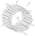
- FIG. 9is a perspective view of an inventive stent.
- FIG. 10is a cross-sectional view of the stent of FIG. 9 taken along line 10 — 10 .
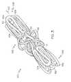
- FIG. 11is a schematic illustrating the connectors which extend between adjacent segments in the stent of FIG. 9 .
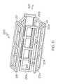
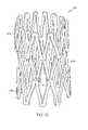
- FIG. 12is a perspective view of another inventive stent.
- FIG. 13is a perspective view of a partially expanded stent similar to that shown in FIG. 12 in the unexpanded state.
- Stent 100comprises at least one segment 104 and desirably, a plurality of segments 104 .
- Segment 104having a proximal end 106 and a distal end 108 , may be any suitable stent segment.
- Segment 104may be capable of supporting a lumen by itself or may only be capable of supporting a bodily lumen in conjunction with other segments.
- the segmentmay be rigid or flexible.
- segment 104is a serpentine segment comprising a plurality of peaks 110 and troughs 112 .
- Peaks 110are disposed at distal end 108 of segment 104 .
- Troughs 112are disposed at proximal end 106 of segment 104 .
- Peaks 110including first peaks 110 a and second peaks 110 b arranged in an alternating pattern about the longitudinal axis 102 of the stent.
- First peaks 110 aare disposed at a first distance from the longitudinal axis of the stent and second peaks 110 b are disposed at a second distance from the longitudinal axis of the stent. The second distance is less than the first distance.
- first peaks 110 adefine a substantially cylindrical outer surface of segment 104 .
- Stent 100is expandable from a first unexpanded configuration, as shown in FIG. 1 to a second expanded configuration of enlarged cross-section as shown in FIG. 2 .
- the first and second peaksare equidistant from the longitudinal axis of the stent.
- second peaks 110 b and optionally, second troughs 112define a substantially cylindrical inner surface of the segment.
- the substantially cylindrical inner surface 114 of the segmentmay be of constant diameter as shown in FIG. 1 or may taper outward toward the substantially cylindrical outer surface 116 of the segment.
- the stent of FIG. 1may comprise a single segment or a plurality of segments where adjacent segments are interconnected one to the other via one or more connectors.
- the connectorsmay be straight or curved, having one or more bends therein.
- the connectorsmay lie entirely on the tubular outer surface of the stent as defined by the segments or may deviate therefrom and include substantial radial components.
- the inventive stents and inventive stent segmentsmay assume other configurations as well.
- Another such stent and segment configurationis shown in FIGS. 3 and 4 .
- Stent 100having a proximal end 106 and a distal end 108 , is formed of two segments 104 which are connected via connectors 118 .
- Each segment 104comprises a plurality of alternating peaks 110 located at the distal end of each segment and troughs 112 located at the proximal end of each segment.
- Distal most segment 104comprises first peaks 110 a and second peaks 110 b .
- First peaks 110 aare disposed at a first distance from the longitudinal axis of the stent and second peaks 110 b are disposed at a second distance from the longitudinal axis of the stent. The second distance is different from the first distance. As shown in FIGS. 3 and 4 , first peaks 110 a define a substantially cylindrical outer surface of segment 104 . Second peaks 110 b form every second peak.
- Proximal most segment 104comprises first troughs 112 a and second troughs 112 b .
- First troughs 112 aare disposed at a first distance from the longitudinal axis of the stent and second troughs 112 b are disposed at a second distance from the longitudinal axis of the stent. The second distance is less than the first distance.
- first troughs 112 adefine a substantially cylindrical outer surface of segment 104 .
- Second troughs 112 bform every second trough. More generally, the second trough may form every nth trough where n is an integer greater than 1.
- the various embodiments of the inventionmay include any pattern of alternating troughs and/or peaks as may be desired. It should noted that the term “alternating” may be used to describe any regular or irregular pattern of peaks and/or troughs as may be desired.
- segments 104are connected by one or more connectors 118 .
- Connector 118is curved and extends out of the outer surface of the stent defined by segments 104 .
- Other types of connectorsmay also be used.
- the connectormay be straight or may have one or more portions which are curved or have bends therein.
- An example of straight connectorsis shown in WO 9626689.
- An example of a connector having bendsis shown in U.S. Pat. No. 6,152,957.
- the ends of the connectormay be circumferentially aligned one with the other or may be circumferentially displaced one from the other. An example of the latter is shown in WO 9626689.
- the connectorsmay lie entirely along the tubular surface of the stent defined by the stent segments or may deviate therefrom.
- the inventionalso contemplates stents comprising a single such segment 104 as well as stents comprising two or more of segments 104 .
- the inventionis also directed to a stent, such as that shown generally at 200 in FIG. 5 in an unexpanded configuration, comprising at least one segment 204 having a plurality of distal closed portions 210 and distal open portions 211 alternating with one another.
- Distal closed portions 210including first distal closed portions 210 a disposed at a first distance from the longitudinal axis 202 of the stent and second distal closed portions 210 b disposed at a second distance from the longitudinal axis of the stent. The second distance is less than the first distance.
- First distal closed portions 210 a and second distal closed portions 210 balternate with one another about the longitudinal axis of the stent.
- First closed portions 210 adefine a substantially cylindrical outer surface of the segment.
- the proximal end of the segmentcomprises a plurality of proximal closed portions 212 and proximal open portions 213 alternating with one another.
- the second distal closed portionsmay define a substantially cylindrical inner surface of the segment.
- the substantially cylindrical inner surface of the segmentmay taper outward toward the substantially cylindrical outer surface of the segment.
- first distal closed portions 210 a and second distal portions 210 bare equidistant from the longitudinal axis of the stent.
- proximal closed portions 212may include first proximal closed portions 212 a disposed at a first distance from the longitudinal axis of the stent and second proximal closed portions 212 b disposed at a second distance from the longitudinal axis of the stent. The second distance is less than the first distance. The first and second proximal closed portions alternate with one another about the longitudinal axis of the stent.
- segment 204may include a plurality of cells 221 with openings therethrough.
- the cellsmay be of any suitable geometry.
- Another example of a suitable segmentis a serpentine segment, for example, segment 104 of FIG. 1 or segment 104 of FIG. 3 .
- Proximal closed portions 212may be aligned with distal closed portions 210 as shown in FIG. 5 .
- the inventionalso contemplates segments in which proximal closed portions are not aligned with distal closed portions.
- the inventionis directed to a stent such as that shown at 300 in an unexpanded configuration in FIGS. 7 and 8 comprising at least one segment 304 having a proximal end and a distal end.
- the distal end of segment 304comprises a plurality of distal closed portions 310 and distal open portions 311 alternating with one another.
- Distal closed portions 310which are adjacent one another are arranged in overlapping relationship about the segment.
- the proximal end of the segmentcomprises a plurality of proximal closed portions 312 and proximal open 313 portions alternating with one another.
- Each distal closed portion 310extends at least partially radially inward.
- the segmentmay be serpentine, as shown in FIGS. 7 and 8 or may be of any other suitable construction including of cellular construction having a plurality of cells with openings therethrough as shown in FIG. 3 , suitably modified.
- the stentmay comprise a single segment as shown in FIG. 7 or a plurality of segments. Where a plurality of segments are provided, segments 304 which are adjacent one another are connected one to the other via one or more connectors 314 .
- the inventionis directed to a stent comprising a plurality of segments which define a cylindrical surface of the stent and which are connected one to the other by one or more connectors which deviate from the tubular surface of the stent.
- Stent 100comprises two segments 104 with a plurality of connectors 118 extending therebetween.
- Connectors 118deviate from the cylindrical surface of the stent and include a portion which extends in a radial direction.
- Connectors 118 as shown in FIG. 3are curved and include a plurality of bends.
- the inventionalso contemplates connectors which are straight and connectors which include only a single bend.
- each connectormay be longitudinally and circumferentially offset or may be longitudinally offset and circumferentially aligned. Any suitable segment may be used including any of those disclosed above. Desirably, the connectors lie on the tubular surface of the stent when the stent is in the expanded state.
- the inventionis also directed to a stent such as that shown generally at 100 in FIG. 9 , comprising a plurality of cylindrical segments 104 a–c each of which comprises a plurality of interconnected struts.
- the cylindrical segmentsinclude a first cylindrical segment 104 a , a second cylindrical segment 104 b connected to first cylindrical segment 104 a and a third cylindrical segment 104 c connected to second cylindrical segment 104 b .
- first cylindrical segment 104 a and second cylindrical segment 104 bat least partially overlap with one another and second cylindrical segment 104 b and third cylindrical segment 104 c at least partially overlap with one another when the stent is in an unexpanded state.
- the stent segmentsare disposed in a herringbone arrangement. Adjacent segments are connected one to the other via one or more connectors. Connectors 118 , as shown in FIGS. 10 and 11 are curved and extend from every third peak region of one segment to every third trough region of an adjacent segment. More generally, the connectors may be in the form of any of the other connectors disclosed herein and may extend from regions other than the peaks and troughs. Moreover, any number of connectors may extend between adjacent segments ranging from one connector up to twice the number of peaks in the segment.
- the segmentsupon expansion of the stent, no longer overlap one another.
- Thismay be achieved by employing curved connectors which are flexible.
- Straight connectors which are flexiblemay also be used.
- the extent of overlap between segments of the stent of FIG. 9is exemplary. It is also within the scope of the invention to have more overlap between adjacent segments of the stent.
- the length of the overlap region between adjacent segmentsmay range from 0% to 75% or more of the length of each segment.
- Stent 100may include any suitable segments including serpentine segments such as those shown in FIG. 3 or segments comprising a plurality of cells with openings therethrough such as that shown in FIG. 6 .
- the cylindrical segmentsmay optionally include overlapping struts.
- the inventionis also directed to stents which comprise a plurality of segments which are disposed in a herringbone pattern.
- An example of such a stentis shown in FIG. 9 .
- Stent 100comprises two segments 104 a of a first radius and one segment 104 b of a second radius smaller than the first segment.
- the stentmay further comprise additional first segments and seconds disposed in an alternating relationship.
- Adjacent segmentsare connected to one another via one or more connectors 118 which extend from peak regions to trough regions. As shown in FIGS. 12 and 13 , each peak is connected to a trough region via a connector.
- Any of the connectors disclosed hereinmay be used to connect adjacent segments together. Desirably, curved connectors such as those shown in FIG. 11 will be used.
- the overlap between adjacent segments of the stent of FIGS. 12 and 13disappears upon further expansion of the stent.
- the extent of overlap between segments of the stent of FIG. 12is exemplary. It is also within the scope of the invention to have more overlap between adjacent segments of the stent.
- the length of the overlap region between adjacent segmentsmay range from 0% to 75% or more of the length of each segment.
- Stent 100may include any suitable segments including serpentine segments such as those shown in FIG. 3 or segments comprising a plurality of cells with openings therethrough such as that shown in FIG. 6 .
- the cylindrical segmentsmay optionally include overlapping struts.
- inventive stents with overlapping segmentsmay be designed such that the increase in the length of the stent upon expansion of the stent resulting from the segments ceasing to overlap offsets any foreshortening of the individual segments so that the stent remains constant in length in the expanded state.
- the inventionis directed to any of the above stents whether in the unexpanded state or in the expanded state.
- inventive stentsin many of the embodiments disclosed herein, are characterized by a reduced delivery profile as compared with stents which do not have overlapping segments. This reduced profile facilitates delivery of the stent.
- inventive stentsin many of the embodiments disclosed herein, are also characterized by an increased flexibility when in the reduced profile.
- Typical prior art stentshave a high concentration of metal or other stent material when crimped. This leaves little room for movement of the stent material which is necessary to accommodate flexing of the stent.
- the inventive multilayer stentsare characterized by a lower concentration of metal or other stent material which provides additional room for movement of the stent material and hence, enhanced flexibility.
- the inventive stents disclosed hereinmay be made of any stent material known in the art including polymeric materials, metals, ceramics and composites.
- Suitable polymeric materialsinclude thermotropic liquid crystal polymers (LCP's).
- the metalmay be stainless steel, cobalt chrome alloys such as spring steel, elgiloy, tantalum or other plastically deformable metals.
- Other suitable metalsinclude shape-memory metals such as nickel-titanium alloys generically known as “nitinol”, platinum/tungsten alloys and titanium alloys, as well as MRI compatible materials.
- the inventive stentsmay include suitable radiopaque coatings.
- the stentsmay be coated with gold or other noble metals or sputtered with tantalum or other metals.
- the stentsmay also be made directly from a radiopaque material to obviate the need for a radiopaque coating or may be made of a material having a radiopaque inner core.
- Other radiopaque metals which may be usedinclude platinum, platinum-tungsten, palladium, platinum-iridium, rhodium, tantalum, or alloys or composites of these metals.
- the inventive stentsmay be coated in part or in its entirety with other biocompatible coatings such as lubricious coatings.
- the inventive stentsmay also be provided with drug-containing coatings which release drugs over time.
- Suitable coatingsinclude a sugar or more generally a carbohydrate and/or a gelatin to maintain the stent on a balloon during delivery of the stent to a desired bodily location.
- Other suitable compounds for treating the stentinclude biodegradable polymers and polymers which are dissolvable in bodily fluids. Portions of the interior and/or exterior of the stent may be coated or impregnated with the compound. Subjecting the stent to such a treatment also may prevent flaring of the ends of the stent during delivery of the stent. Mechanical retention devices may also be used to maintain the stent on the balloon during delivery.
- inventive stentsAny suitable manufacturing process may be used for producing the inventive stents including laser cutting, chemical etching, electroforming or stamping of a tube.
- inventive stentsmay also be manufactured by laser cutting, chemically etching, stamping or electroforming a flat sheet, rolling the sheet and welding the sheet, by electrode discharge machining, or by molding the stent with the desired design.
- inventive stentsmay also be made by growing or extruding or winding a stent with the inventive patterns. Already existing stents may also be bent and/crimped into the inventive stent configurations.
- the inventionis directed to a method of producing a stent comprising the steps of providing a corrugated member having a first end, a second end and a longitudinal axis and processing the member into a stent, the processing step including removing material from the corrugated member so as to form a desired stent pattern.
- the corrugated membermay be a tube or a sheet. Where the member is a sheet, the processing step further includes the step of forming a tube from the corrugated member.
- the materialmay be removed during the processing step by any suitable technique including cutting, laser etching, chemical etching, stamping and electrode discharge machining.
- the corrugationsextend longitudinally. Also desirably, the corrugations extend from the first end of the member to the second end of the tube, longitudinally, spirally or otherwise.
- the stent patternmay include serpentine segments and/or cellular segments such as, but not limited to, those disclosed above.
- the inventionis also directed to stents made in accordance with the inventive methods disclosed herein.
- inventive stentsmay be provided in mechanically expandable form, in self-expanding form or as a hybrid of the two.
- Mechanically expandable stents, in accordance with the invention,may be expanded using any suitable mechanical device including a balloon.
- the inventive stentsmay be used for coronary arteries, peripheral arteries, arteries of the neck and intracranial arteries. More generally, the inventive stents may be used for any vessel of the human body including but not limited to arteries, veins, biliary ducts, urethras, fallopian tubes, bronchial tubes, the trachea and the esophagus.
- Suitable stent delivery devicessuch as those disclosed in U.S. Pat. No. 6,123,712, U.S. Pat. No. 6,120,522 and U.S. Pat. No. 5,957,930 may be used to deliver the inventive stents to the desired bodily location.
- the choice of delivery devicewill depend on whether a self-expanding or balloon expandable stent is used.
- the inventive stentsmay also be used as the framework for a graft.
- Suitable coveringsinclude nylon, collagen, PTFE and expanded PTFE, polyethylene terephthalate and KEVLAR, or any of the materials disclosed in U.S. Pat. No. 5,824,046 and U.S. Pat. No. 5,755,770. More generally, any known graft material may be used including synthetic polymers such as polyethylene, polypropylene, polyurethane, polyglycolic acid, polyesters, polyamides, their mixtures, blends, copolymers, mixtures, blends and copolymers.
- any dependent claim which followsshould be taken as alternatively written in a multiple dependent form from all prior claims which possess all antecedents referenced in such dependent claim if such multiple dependent format is an accepted format within the jurisdiction (e.g. each claim depending directly from claim 1 should be alternatively taken as depending from all previous claims).
- each claim depending directly from claim 1should be alternatively taken as depending from all previous claims.
- the following dependent claimsshould each be also taken as alternatively written in each singly dependent claim format which creates a dependency from a prior antecedent-possessing claim other than the specific claim listed in such dependent claim below.
Landscapes
- Health & Medical Sciences (AREA)
- Engineering & Computer Science (AREA)
- Biomedical Technology (AREA)
- Heart & Thoracic Surgery (AREA)
- Life Sciences & Earth Sciences (AREA)
- Cardiology (AREA)
- Oral & Maxillofacial Surgery (AREA)
- Transplantation (AREA)
- Veterinary Medicine (AREA)
- Vascular Medicine (AREA)
- Public Health (AREA)
- Animal Behavior & Ethology (AREA)
- General Health & Medical Sciences (AREA)
- Optics & Photonics (AREA)
- Physics & Mathematics (AREA)
- Prostheses (AREA)
- Media Introduction/Drainage Providing Device (AREA)
- Materials For Medical Uses (AREA)
Abstract
Description
Claims (6)
Priority Applications (7)
| Application Number | Priority Date | Filing Date | Title |
|---|---|---|---|
| US10/055,307US7060089B2 (en) | 2002-01-23 | 2002-01-23 | Multi-layer stent |
| CA002472714ACA2472714A1 (en) | 2002-01-23 | 2003-01-08 | Multi-layer stent |
| AT03701253TATE415917T1 (en) | 2002-01-23 | 2003-01-08 | MULTI-LAYER STENT |
| PCT/US2003/000466WO2003061528A1 (en) | 2002-01-23 | 2003-01-08 | Multi-layer stent |
| DE60325015TDE60325015D1 (en) | 2002-01-23 | 2003-01-08 | MULTILAYER STENT |
| JP2003561474AJP2005515022A (en) | 2002-01-23 | 2003-01-08 | Multilayer stent |
| EP03701253AEP1469792B1 (en) | 2002-01-23 | 2003-01-08 | Multi-layer stent |
Applications Claiming Priority (1)
| Application Number | Priority Date | Filing Date | Title |
|---|---|---|---|
| US10/055,307US7060089B2 (en) | 2002-01-23 | 2002-01-23 | Multi-layer stent |
Publications (2)
| Publication Number | Publication Date |
|---|---|
| US20030139799A1 US20030139799A1 (en) | 2003-07-24 |
| US7060089B2true US7060089B2 (en) | 2006-06-13 |
Family
ID=21996997
Family Applications (1)
| Application Number | Title | Priority Date | Filing Date |
|---|---|---|---|
| US10/055,307Expired - Fee RelatedUS7060089B2 (en) | 2002-01-23 | 2002-01-23 | Multi-layer stent |
Country Status (7)
| Country | Link |
|---|---|
| US (1) | US7060089B2 (en) |
| EP (1) | EP1469792B1 (en) |
| JP (1) | JP2005515022A (en) |
| AT (1) | ATE415917T1 (en) |
| CA (1) | CA2472714A1 (en) |
| DE (1) | DE60325015D1 (en) |
| WO (1) | WO2003061528A1 (en) |
Cited By (28)
| Publication number | Priority date | Publication date | Assignee | Title |
|---|---|---|---|---|
| US20040260386A1 (en)* | 2003-01-31 | 2004-12-23 | Shalaby Shalaby W. | Absorbable / biodegradable tubular stent and methods of making the same |
| US20050107865A1 (en)* | 2003-05-06 | 2005-05-19 | Anton Clifford | Endoprosthesis having foot extensions |
| US20050121411A1 (en)* | 2002-10-29 | 2005-06-09 | Microfabrica Inc. | Medical devices and EFAB methods and apparatus for producing them |
| US20050192657A1 (en)* | 2004-02-26 | 2005-09-01 | Colen Fredericus A. | Medical devices |
| US20060015173A1 (en)* | 2003-05-06 | 2006-01-19 | Anton Clifford | Endoprosthesis having foot extensions |
| US20060020322A1 (en)* | 2004-07-21 | 2006-01-26 | Alexander Leynov | Expandable framework with overlapping connectors |
| US20060085068A1 (en)* | 2004-10-18 | 2006-04-20 | Barry Richard J | Spine microsurgery techniques, training aids and implants |
| US20060142844A1 (en)* | 2002-05-08 | 2006-06-29 | David Lowe | Endoprosthesis having foot extensions |
| US20070021834A1 (en)* | 2003-05-06 | 2007-01-25 | Eugene Young | Endoprosthesis having foot extensions |
| US20070055348A1 (en)* | 2005-09-02 | 2007-03-08 | Medtronic Vascular, Inc. | Tabbed stent with minimum compressed profile |
| US20070088425A1 (en)* | 2005-10-13 | 2007-04-19 | Cook Incorporated | Endoluminal prosthesis |
| USD556905S1 (en)* | 2004-10-18 | 2007-12-04 | Barry Richard J | Spinal fusion implant |
| USD566277S1 (en) | 2005-12-16 | 2008-04-08 | Richard Barry | Spinal fusion implant |
| US20100023046A1 (en)* | 2008-07-24 | 2010-01-28 | Aga Medical Corporation | Multi-layered medical device for treating a target site and associated method |
| US20100137973A1 (en)* | 2008-12-02 | 2010-06-03 | Boston Scientific Scimed, Inc. | Layered Bifurcation Stent |
| US20100179641A1 (en)* | 2007-02-15 | 2010-07-15 | Ryan Timothy R | Multi-layered stents and methods of implanting |
| US20130218255A1 (en)* | 2010-08-26 | 2013-08-22 | Acandis Gmbh & Co. Kg | Medical device and system having such a device |
| US8999364B2 (en) | 2004-06-15 | 2015-04-07 | Nanyang Technological University | Implantable article, method of forming same and method for reducing thrombogenicity |
| US9220899B2 (en) | 2010-08-26 | 2015-12-29 | Acandis Gmbh & Co. Kg | Electrode for medical applications, system having an electrode, and method for producing an electrode |
| CN105208977A (en)* | 2013-03-13 | 2015-12-30 | 波士顿科学国际有限公司 | Anti-migration tissue anchoring system for a fully covered stent |
| US9526623B2 (en) | 2012-05-30 | 2016-12-27 | Newvert Ltd. | Spinal disc annulus closure device |
| US9908143B2 (en) | 2008-06-20 | 2018-03-06 | Amaranth Medical Pte. | Stent fabrication via tubular casting processes |
| US10219921B2 (en) | 2014-10-02 | 2019-03-05 | Boston Scientific Scimed, Inc. | Controlled ingrowth feature for antimigration |
| US20190133795A1 (en)* | 2017-11-03 | 2019-05-09 | Covidien Lp | Meshes, devices and methods for treating vascular defects |
| US10646359B2 (en) | 2008-06-20 | 2020-05-12 | Amaranth Medical Pte. | Stent fabrication via tubular casting processes |
| US20210128328A1 (en)* | 2009-04-02 | 2021-05-06 | Q3 Medical Devices Limited | Stent |
| US11759341B2 (en) | 2020-01-13 | 2023-09-19 | Boston Scientific Scimed, Inc. | Anti-migration stent |
| US11931484B2 (en) | 2008-06-20 | 2024-03-19 | Razmodics Llc | Composite stent having multi-axial flexibility and method of manufacture thereof |
Families Citing this family (77)
| Publication number | Priority date | Publication date | Assignee | Title |
|---|---|---|---|---|
| US7713297B2 (en) | 1998-04-11 | 2010-05-11 | Boston Scientific Scimed, Inc. | Drug-releasing stent with ceramic-containing layer |
| WO2003002243A2 (en) | 2001-06-27 | 2003-01-09 | Remon Medical Technologies Ltd. | Method and device for electrochemical formation of therapeutic species in vivo |
| US7060089B2 (en) | 2002-01-23 | 2006-06-13 | Boston Scientific Scimed, Inc. | Multi-layer stent |
| AU2003239369A1 (en)* | 2002-05-06 | 2003-11-17 | Abbott Laboratories | Endoprosthesis for controlled contraction and expansion |
| US6945995B2 (en)* | 2002-08-29 | 2005-09-20 | Boston Scientific Scimed, Inc. | Stent overlap point markers |
| US6997946B2 (en)* | 2002-11-27 | 2006-02-14 | Boston Scientific Scimed, Inc. | Expandable stents |
| ATE445424T1 (en) | 2004-07-05 | 2009-10-15 | Ziscoat N V | BIOCOMPATIBLE COATING OF MEDICAL DEVICES USING MOLECULAR SIEVES |
| JP4876916B2 (en)* | 2004-07-30 | 2012-02-15 | 株式会社カネカ | Stent |
| US7240516B2 (en)* | 2004-08-03 | 2007-07-10 | Medtronic Vascular, Inc. | Flexible resheathable stent design |
| US8313524B2 (en) | 2004-08-31 | 2012-11-20 | C. R. Bard, Inc. | Self-sealing PTFE graft with kink resistance |
| DE102005019649A1 (en)* | 2005-04-26 | 2006-11-02 | Alveolus Inc. | Flexible stent for positioning in lumen of esophagus comprises tube and stabilization members defined circumferentially about tube, where each member extends inwardly in tube to define inner diameter that is less than inner diameter of tube |
| JP2009501027A (en) | 2005-06-17 | 2009-01-15 | シー・アール・バード・インコーポレイテツド | Vascular graft with kinking resistance after tightening |
| EP1769774A1 (en)* | 2005-10-03 | 2007-04-04 | Noureddine Frid | Radiopaque endoprostheses |
| WO2007056762A2 (en)* | 2005-11-09 | 2007-05-18 | C.R. Bard Inc. | Grafts and stent grafts having a radiopaque beading |
| CA2626598A1 (en)* | 2005-11-09 | 2007-05-18 | C.R. Bard Inc. | Grafts and stent grafts having a radiopaque marker |
| US8840660B2 (en) | 2006-01-05 | 2014-09-23 | Boston Scientific Scimed, Inc. | Bioerodible endoprostheses and methods of making the same |
| US8089029B2 (en) | 2006-02-01 | 2012-01-03 | Boston Scientific Scimed, Inc. | Bioabsorbable metal medical device and method of manufacture |
| US20070224235A1 (en) | 2006-03-24 | 2007-09-27 | Barron Tenney | Medical devices having nanoporous coatings for controlled therapeutic agent delivery |
| US8187620B2 (en) | 2006-03-27 | 2012-05-29 | Boston Scientific Scimed, Inc. | Medical devices comprising a porous metal oxide or metal material and a polymer coating for delivering therapeutic agents |
| US8048150B2 (en) | 2006-04-12 | 2011-11-01 | Boston Scientific Scimed, Inc. | Endoprosthesis having a fiber meshwork disposed thereon |
| US20070282433A1 (en)* | 2006-06-01 | 2007-12-06 | Limon Timothy A | Stent with retention protrusions formed during crimping |
| US8815275B2 (en) | 2006-06-28 | 2014-08-26 | Boston Scientific Scimed, Inc. | Coatings for medical devices comprising a therapeutic agent and a metallic material |
| WO2008002778A2 (en) | 2006-06-29 | 2008-01-03 | Boston Scientific Limited | Medical devices with selective coating |
| EP2054537A2 (en) | 2006-08-02 | 2009-05-06 | Boston Scientific Scimed, Inc. | Endoprosthesis with three-dimensional disintegration control |
| EP2068757B1 (en) | 2006-09-14 | 2011-05-11 | Boston Scientific Limited | Medical devices with drug-eluting coating |
| JP2010503489A (en) | 2006-09-15 | 2010-02-04 | ボストン サイエンティフィック リミテッド | Biodegradable endoprosthesis and method for producing the same |
| ES2357661T3 (en) | 2006-09-15 | 2011-04-28 | Boston Scientific Scimed, Inc. | BIOEROSIONABLE ENDOPROOTHESIS WITH BIOESTABLE INORGANIC LAYERS. |
| EP2959925B1 (en) | 2006-09-15 | 2018-08-29 | Boston Scientific Limited | Medical devices and methods of making the same |
| WO2008034066A1 (en) | 2006-09-15 | 2008-03-20 | Boston Scientific Limited | Bioerodible endoprostheses and methods of making the same |
| WO2008036548A2 (en) | 2006-09-18 | 2008-03-27 | Boston Scientific Limited | Endoprostheses |
| US9198749B2 (en) | 2006-10-12 | 2015-12-01 | C. R. Bard, Inc. | Vascular grafts with multiple channels and methods for making |
| CA2668769A1 (en)* | 2006-11-09 | 2008-05-22 | Boston Scientific Limited | Endoprosthesis with coatings |
| US20080294236A1 (en)* | 2007-05-23 | 2008-11-27 | Boston Scientific Scimed, Inc. | Endoprosthesis with Select Ceramic and Polymer Coatings |
| US7981150B2 (en)* | 2006-11-09 | 2011-07-19 | Boston Scientific Scimed, Inc. | Endoprosthesis with coatings |
| ES2506144T3 (en) | 2006-12-28 | 2014-10-13 | Boston Scientific Limited | Bioerodible endoprosthesis and their manufacturing procedure |
| US8431149B2 (en) | 2007-03-01 | 2013-04-30 | Boston Scientific Scimed, Inc. | Coated medical devices for abluminal drug delivery |
| US8070797B2 (en) | 2007-03-01 | 2011-12-06 | Boston Scientific Scimed, Inc. | Medical device with a porous surface for delivery of a therapeutic agent |
| US8067054B2 (en) | 2007-04-05 | 2011-11-29 | Boston Scientific Scimed, Inc. | Stents with ceramic drug reservoir layer and methods of making and using the same |
| US7976915B2 (en) | 2007-05-23 | 2011-07-12 | Boston Scientific Scimed, Inc. | Endoprosthesis with select ceramic morphology |
| US7942926B2 (en) | 2007-07-11 | 2011-05-17 | Boston Scientific Scimed, Inc. | Endoprosthesis coating |
| US8002823B2 (en) | 2007-07-11 | 2011-08-23 | Boston Scientific Scimed, Inc. | Endoprosthesis coating |
| EP2187988B1 (en) | 2007-07-19 | 2013-08-21 | Boston Scientific Limited | Endoprosthesis having a non-fouling surface |
| US8815273B2 (en) | 2007-07-27 | 2014-08-26 | Boston Scientific Scimed, Inc. | Drug eluting medical devices having porous layers |
| US7931683B2 (en) | 2007-07-27 | 2011-04-26 | Boston Scientific Scimed, Inc. | Articles having ceramic coated surfaces |
| WO2009018340A2 (en) | 2007-07-31 | 2009-02-05 | Boston Scientific Scimed, Inc. | Medical device coating by laser cladding |
| JP2010535541A (en) | 2007-08-03 | 2010-11-25 | ボストン サイエンティフィック リミテッド | Coating for medical devices with large surface area |
| US8052745B2 (en) | 2007-09-13 | 2011-11-08 | Boston Scientific Scimed, Inc. | Endoprosthesis |
| US7938855B2 (en) | 2007-11-02 | 2011-05-10 | Boston Scientific Scimed, Inc. | Deformable underlayer for stent |
| US8029554B2 (en) | 2007-11-02 | 2011-10-04 | Boston Scientific Scimed, Inc. | Stent with embedded material |
| US8216632B2 (en) | 2007-11-02 | 2012-07-10 | Boston Scientific Scimed, Inc. | Endoprosthesis coating |
| US20090210049A1 (en)* | 2008-02-15 | 2009-08-20 | Joseph Michael Thielen | Peripheral overlap stent |
| JP5537540B2 (en)* | 2008-04-01 | 2014-07-02 | メドトロニック ヴァスキュラー インコーポレイテッド | Double wall stent system |
| US8920491B2 (en) | 2008-04-22 | 2014-12-30 | Boston Scientific Scimed, Inc. | Medical devices having a coating of inorganic material |
| US8932346B2 (en) | 2008-04-24 | 2015-01-13 | Boston Scientific Scimed, Inc. | Medical devices having inorganic particle layers |
| US7998192B2 (en) | 2008-05-09 | 2011-08-16 | Boston Scientific Scimed, Inc. | Endoprostheses |
| US8236046B2 (en) | 2008-06-10 | 2012-08-07 | Boston Scientific Scimed, Inc. | Bioerodible endoprosthesis |
| EP2303350A2 (en) | 2008-06-18 | 2011-04-06 | Boston Scientific Scimed, Inc. | Endoprosthesis coating |
| US7985252B2 (en) | 2008-07-30 | 2011-07-26 | Boston Scientific Scimed, Inc. | Bioerodible endoprosthesis |
| US20100145433A1 (en)* | 2008-09-30 | 2010-06-10 | Abbott Cardiovascular Systems, Inc. | Endoprostheses for deployment in a body lumen |
| US8382824B2 (en) | 2008-10-03 | 2013-02-26 | Boston Scientific Scimed, Inc. | Medical implant having NANO-crystal grains with barrier layers of metal nitrides or fluorides |
| US8231980B2 (en) | 2008-12-03 | 2012-07-31 | Boston Scientific Scimed, Inc. | Medical implants including iridium oxide |
| DE102009010824B4 (en)* | 2009-02-26 | 2017-08-17 | Acandis Gmbh & Co. Kg | Medical implant, method for its production and method for introducing a medical implant into a delivery system |
| EP2403546A2 (en) | 2009-03-02 | 2012-01-11 | Boston Scientific Scimed, Inc. | Self-buffering medical implants |
| US8071156B2 (en) | 2009-03-04 | 2011-12-06 | Boston Scientific Scimed, Inc. | Endoprostheses |
| US8287937B2 (en) | 2009-04-24 | 2012-10-16 | Boston Scientific Scimed, Inc. | Endoprosthese |
| US8668732B2 (en) | 2010-03-23 | 2014-03-11 | Boston Scientific Scimed, Inc. | Surface treated bioerodible metal endoprostheses |
| US11484318B2 (en) | 2011-01-17 | 2022-11-01 | Artio Medical, Inc. | Expandable body device and method of use |
| CA2822311C (en)* | 2011-01-17 | 2021-10-19 | Novita Therapeutics, Llc | Detachable metal balloon delivery device and method |
| CA3049059C (en) | 2012-01-17 | 2023-03-07 | Metactive Medical, Inc. | Expandable body device and method of use |
| DE102013104062A1 (en)* | 2013-04-22 | 2014-10-23 | Novatech Sa | stent |
| EP3193746A4 (en) | 2014-09-17 | 2018-10-31 | Metactive Medical, Inc. | Expandable body device and method of use |
| US10213307B2 (en)* | 2014-11-05 | 2019-02-26 | Medtronic Vascular, Inc. | Transcatheter valve prosthesis having an external skirt for sealing and preventing paravalvular leakage |
| CN106473848B (en)* | 2015-08-31 | 2018-09-11 | 上海圣博艾医疗科技有限公司 | Prostate bracket |
| CN106137483B (en)* | 2016-07-21 | 2018-10-02 | 成都嘉宝祥生物科技有限公司 | A kind of coronary vessel stent production method |
| GB201616777D0 (en) | 2016-10-03 | 2016-11-16 | Univ Southampton | A frame for an implantable medical device and a method of manufacturing a frame for an implantable medical device |
| AU2018239680A1 (en) | 2017-03-24 | 2019-10-10 | Artio Medical, Inc. | Medical devices comprising detachable balloons and methods of manufacturing and use |
| CN112603591B (en)* | 2020-12-01 | 2022-12-02 | 深圳市先健畅通医疗有限公司 | Covered stent |
Citations (59)
| Publication number | Priority date | Publication date | Assignee | Title |
|---|---|---|---|---|
| US4503569A (en) | 1983-03-03 | 1985-03-12 | Dotter Charles T | Transluminally placed expandable graft prosthesis |
| US4512338A (en) | 1983-01-25 | 1985-04-23 | Balko Alexander B | Process for restoring patency to body vessels |
| US4732152A (en) | 1984-12-05 | 1988-03-22 | Medinvent S.A. | Device for implantation and a method of implantation in a vessel using such device |
| US4733665A (en) | 1985-11-07 | 1988-03-29 | Expandable Grafts Partnership | Expandable intraluminal graft, and method and apparatus for implanting an expandable intraluminal graft |
| US4768507A (en) | 1986-02-24 | 1988-09-06 | Medinnovations, Inc. | Intravascular stent and percutaneous insertion catheter system for the dilation of an arterial stenosis and the prevention of arterial restenosis |
| US4820298A (en) | 1987-11-20 | 1989-04-11 | Leveen Eric G | Internal vascular prosthesis |
| US4830003A (en) | 1988-06-17 | 1989-05-16 | Wolff Rodney G | Compressive stent and delivery system |
| US4848343A (en) | 1986-10-31 | 1989-07-18 | Medinvent S.A. | Device for transluminal implantation |
| US4886062A (en) | 1987-10-19 | 1989-12-12 | Medtronic, Inc. | Intravascular radially expandable stent and method of implant |
| US4907336A (en) | 1987-03-13 | 1990-03-13 | Cook Incorporated | Method of making an endovascular stent and delivery system |
| CA2008312A1 (en) | 1989-01-26 | 1990-07-26 | Ulrich Sigwart | Intravascular endoprothesis |
| US4990155A (en) | 1989-05-19 | 1991-02-05 | Wilkoff Howard M | Surgical stent method and apparatus |
| CA2025626A1 (en) | 1989-09-27 | 1991-03-28 | Jay R. Goldberg | Biodegradable stent |
| US5019090A (en) | 1988-09-01 | 1991-05-28 | Corvita Corporation | Radially expandable endoprosthesis and the like |
| US5234456A (en) | 1990-02-08 | 1993-08-10 | Pfizer Hospital Products Group, Inc. | Hydrophilic stent |
| US5258027A (en)* | 1991-01-24 | 1993-11-02 | Willy Rusch Ag | Trachreal prosthesis |
| US5258020A (en) | 1990-09-14 | 1993-11-02 | Michael Froix | Method of using expandable polymeric stent with memory |
| US5443458A (en) | 1992-12-22 | 1995-08-22 | Advanced Cardiovascular Systems, Inc. | Multilayered biodegradable stent and method of manufacture |
| WO1996014808A1 (en) | 1994-11-09 | 1996-05-23 | Endotex Interventional Systems, Inc. | Delivery catheter and graft for aneurysm repair |
| WO1996026689A1 (en) | 1995-03-01 | 1996-09-06 | Scimed Life Systems, Inc. | Improved longitudinally flexible expandable stent |
| US5618299A (en) | 1993-04-23 | 1997-04-08 | Advanced Cardiovascular Systems, Inc. | Ratcheting stent |
| US5645559A (en) | 1992-05-08 | 1997-07-08 | Schneider (Usa) Inc | Multiple layer stent |
| US5667523A (en)* | 1995-04-28 | 1997-09-16 | Impra, Inc. | Dual supported intraluminal graft |
| WO1998014137A1 (en) | 1996-10-01 | 1998-04-09 | Numed, Inc. | Expandable stent |
| US5755781A (en) | 1996-08-06 | 1998-05-26 | Iowa-India Investments Company Limited | Embodiments of multiple interconnected stents |
| US5755770A (en) | 1995-01-31 | 1998-05-26 | Boston Scientific Corporatiion | Endovascular aortic graft |
| US5824046A (en) | 1996-09-27 | 1998-10-20 | Scimed Life Systems, Inc. | Covered stent |
| US5843168A (en) | 1997-03-31 | 1998-12-01 | Medtronic, Inc. | Double wave stent with strut |
| US5843120A (en) | 1994-03-17 | 1998-12-01 | Medinol Ltd. | Flexible-expandable stent |
| US5855597A (en) | 1997-05-07 | 1999-01-05 | Iowa-India Investments Co. Limited | Stent valve and stent graft for percutaneous surgery |
| US5873906A (en) | 1994-09-08 | 1999-02-23 | Gore Enterprise Holdings, Inc. | Procedures for introducing stents and stent-grafts |
| DE19746882A1 (en) | 1997-10-23 | 1999-04-29 | Angiomed Ag | Expandable stent for tubular anatomical structures such as bile-ducts |
| WO1999030638A1 (en) | 1997-12-12 | 1999-06-24 | Microval (S.A.R.L.) | Coronary prosthesis |
| US5916234A (en) | 1993-12-28 | 1999-06-29 | Advanced Cardiovascular Systems, Inc. | Expandable stents and method for making same |
| US5957930A (en) | 1996-09-27 | 1999-09-28 | Scimed Life Systems, Inc. | Stent deployment catheter with midshaft seal |
| US5980565A (en) | 1997-10-20 | 1999-11-09 | Iowa-India Investments Company Limited | Sandwich stent |
| US6056767A (en) | 1997-09-12 | 2000-05-02 | Laboratoires Nycomed S.A. | System for the treatment of a body duct and process for its manufacture |
| US6083257A (en) | 1995-11-01 | 2000-07-04 | Biocompatibles Limited | Braided stent |
| US6099559A (en) | 1998-05-28 | 2000-08-08 | Medtronic Ave, Inc. | Endoluminal support assembly with capped ends |
| EP0878173B1 (en) | 1997-05-14 | 2000-08-09 | Jomed Implantate GmbH | Stent-graft |
| US6120522A (en) | 1998-08-27 | 2000-09-19 | Scimed Life Systems, Inc. | Self-expanding stent delivery catheter |
| US6123712A (en) | 1996-08-23 | 2000-09-26 | Scimed Life Systems, Inc. | Balloon catheter with stent securement means |
| US6152957A (en) | 1996-04-26 | 2000-11-28 | Jang; G. David | Intravascular stent |
| WO2000071052A1 (en) | 1999-05-19 | 2000-11-30 | Bernd Starck | Highly flexible coating for stents and/or stent grafts and/or vascular stent prostheses |
| US6176872B1 (en) | 1995-08-15 | 2001-01-23 | Ethicon, Inc. | Radial strength stent |
| WO2001006952A1 (en) | 1999-07-16 | 2001-02-01 | Med Institute, Inc. | Stent adapted for tangle-free deployment |
| US6214037B1 (en) | 1999-03-18 | 2001-04-10 | Fossa Industries, Llc | Radially expanding stent |
| US6231598B1 (en)* | 1997-09-24 | 2001-05-15 | Med Institute, Inc. | Radially expandable stent |
| US6287335B1 (en) | 1999-04-26 | 2001-09-11 | William J. Drasler | Intravascular folded tubular endoprosthesis |
| WO2001085064A1 (en) | 2000-05-05 | 2001-11-15 | The Board Of Trustees Of The Leland Stanford Junior University | Multilayer stents having enhanced flexibility and hoop strength |
| US6334869B1 (en)* | 1995-10-30 | 2002-01-01 | World Medical Manufacturing Corporation | Endoluminal prosthesis |
| US6340366B2 (en) | 1998-12-08 | 2002-01-22 | Bandula Wijay | Stent with nested or overlapping rings |
| WO2002013725A2 (en) | 2000-08-17 | 2002-02-21 | Advanced Cardiovascular Systems, Inc. | Stent having overlapping struts |
| US6383216B1 (en) | 1992-08-06 | 2002-05-07 | William Cook Europe A/S | Implantable self expanding prosthetic device |
| US6383171B1 (en) | 1999-10-12 | 2002-05-07 | Allan Will | Methods and devices for protecting a passageway in a body when advancing devices through the passageway |
| US6547818B1 (en) | 2000-10-20 | 2003-04-15 | Endotex Interventional Systems, Inc. | Selectively thinned coiled-sheet stents and methods for making them |
| US20030139799A1 (en) | 2002-01-23 | 2003-07-24 | Ley Timothy J. | Multi-layer stent |
| US6673106B2 (en) | 2001-06-14 | 2004-01-06 | Cordis Neurovascular, Inc. | Intravascular stent device |
| US6776793B2 (en)* | 1995-03-01 | 2004-08-17 | Scimed Life Systems, Inc. | Longitudinally flexible expandable stent |
- 2002
- 2002-01-23USUS10/055,307patent/US7060089B2/ennot_activeExpired - Fee Related
- 2003
- 2003-01-08CACA002472714Apatent/CA2472714A1/ennot_activeAbandoned
- 2003-01-08JPJP2003561474Apatent/JP2005515022A/enactivePending
- 2003-01-08ATAT03701253Tpatent/ATE415917T1/ennot_activeIP Right Cessation
- 2003-01-08DEDE60325015Tpatent/DE60325015D1/ennot_activeExpired - Lifetime
- 2003-01-08WOPCT/US2003/000466patent/WO2003061528A1/enactiveApplication Filing
- 2003-01-08EPEP03701253Apatent/EP1469792B1/ennot_activeExpired - Lifetime
Patent Citations (65)
| Publication number | Priority date | Publication date | Assignee | Title |
|---|---|---|---|---|
| US4512338A (en) | 1983-01-25 | 1985-04-23 | Balko Alexander B | Process for restoring patency to body vessels |
| US4503569A (en) | 1983-03-03 | 1985-03-12 | Dotter Charles T | Transluminally placed expandable graft prosthesis |
| US4732152A (en) | 1984-12-05 | 1988-03-22 | Medinvent S.A. | Device for implantation and a method of implantation in a vessel using such device |
| US4733665B1 (en) | 1985-11-07 | 1994-01-11 | Expandable Grafts Partnership | Expandable intraluminal graft,and method and apparatus for implanting an expandable intraluminal graft |
| US4733665A (en) | 1985-11-07 | 1988-03-29 | Expandable Grafts Partnership | Expandable intraluminal graft, and method and apparatus for implanting an expandable intraluminal graft |
| US4733665C2 (en) | 1985-11-07 | 2002-01-29 | Expandable Grafts Partnership | Expandable intraluminal graft and method and apparatus for implanting an expandable intraluminal graft |
| US4768507A (en) | 1986-02-24 | 1988-09-06 | Medinnovations, Inc. | Intravascular stent and percutaneous insertion catheter system for the dilation of an arterial stenosis and the prevention of arterial restenosis |
| US4848343A (en) | 1986-10-31 | 1989-07-18 | Medinvent S.A. | Device for transluminal implantation |
| US4907336A (en) | 1987-03-13 | 1990-03-13 | Cook Incorporated | Method of making an endovascular stent and delivery system |
| US4886062A (en) | 1987-10-19 | 1989-12-12 | Medtronic, Inc. | Intravascular radially expandable stent and method of implant |
| US4820298A (en) | 1987-11-20 | 1989-04-11 | Leveen Eric G | Internal vascular prosthesis |
| US4830003A (en) | 1988-06-17 | 1989-05-16 | Wolff Rodney G | Compressive stent and delivery system |
| US5019090A (en) | 1988-09-01 | 1991-05-28 | Corvita Corporation | Radially expandable endoprosthesis and the like |
| CA2008312A1 (en) | 1989-01-26 | 1990-07-26 | Ulrich Sigwart | Intravascular endoprothesis |
| US4990155A (en) | 1989-05-19 | 1991-02-05 | Wilkoff Howard M | Surgical stent method and apparatus |
| CA2025626A1 (en) | 1989-09-27 | 1991-03-28 | Jay R. Goldberg | Biodegradable stent |
| US5234456A (en) | 1990-02-08 | 1993-08-10 | Pfizer Hospital Products Group, Inc. | Hydrophilic stent |
| US5258020A (en) | 1990-09-14 | 1993-11-02 | Michael Froix | Method of using expandable polymeric stent with memory |
| US5258027A (en)* | 1991-01-24 | 1993-11-02 | Willy Rusch Ag | Trachreal prosthesis |
| US5645559A (en) | 1992-05-08 | 1997-07-08 | Schneider (Usa) Inc | Multiple layer stent |
| US6383216B1 (en) | 1992-08-06 | 2002-05-07 | William Cook Europe A/S | Implantable self expanding prosthetic device |
| US5443458A (en) | 1992-12-22 | 1995-08-22 | Advanced Cardiovascular Systems, Inc. | Multilayered biodegradable stent and method of manufacture |
| US5618299A (en) | 1993-04-23 | 1997-04-08 | Advanced Cardiovascular Systems, Inc. | Ratcheting stent |
| US5916234A (en) | 1993-12-28 | 1999-06-29 | Advanced Cardiovascular Systems, Inc. | Expandable stents and method for making same |
| US5843120A (en) | 1994-03-17 | 1998-12-01 | Medinol Ltd. | Flexible-expandable stent |
| US5873906A (en) | 1994-09-08 | 1999-02-23 | Gore Enterprise Holdings, Inc. | Procedures for introducing stents and stent-grafts |
| US5769887A (en) | 1994-11-09 | 1998-06-23 | Endotex Interventional Systems, Inc. | Delivery catheter and graft for aneurysm repair |
| WO1996014808A1 (en) | 1994-11-09 | 1996-05-23 | Endotex Interventional Systems, Inc. | Delivery catheter and graft for aneurysm repair |
| US5755770A (en) | 1995-01-31 | 1998-05-26 | Boston Scientific Corporatiion | Endovascular aortic graft |
| US6348065B1 (en)* | 1995-03-01 | 2002-02-19 | Scimed Life Systems, Inc. | Longitudinally flexible expandable stent |
| WO1996026689A1 (en) | 1995-03-01 | 1996-09-06 | Scimed Life Systems, Inc. | Improved longitudinally flexible expandable stent |
| US6776793B2 (en)* | 1995-03-01 | 2004-08-17 | Scimed Life Systems, Inc. | Longitudinally flexible expandable stent |
| US5667523A (en)* | 1995-04-28 | 1997-09-16 | Impra, Inc. | Dual supported intraluminal graft |
| US6176872B1 (en) | 1995-08-15 | 2001-01-23 | Ethicon, Inc. | Radial strength stent |
| US6334869B1 (en)* | 1995-10-30 | 2002-01-01 | World Medical Manufacturing Corporation | Endoluminal prosthesis |
| US6083257A (en) | 1995-11-01 | 2000-07-04 | Biocompatibles Limited | Braided stent |
| US6152957A (en) | 1996-04-26 | 2000-11-28 | Jang; G. David | Intravascular stent |
| US5755781A (en) | 1996-08-06 | 1998-05-26 | Iowa-India Investments Company Limited | Embodiments of multiple interconnected stents |
| US6123712A (en) | 1996-08-23 | 2000-09-26 | Scimed Life Systems, Inc. | Balloon catheter with stent securement means |
| US5957930A (en) | 1996-09-27 | 1999-09-28 | Scimed Life Systems, Inc. | Stent deployment catheter with midshaft seal |
| US5824046A (en) | 1996-09-27 | 1998-10-20 | Scimed Life Systems, Inc. | Covered stent |
| WO1998014137A1 (en) | 1996-10-01 | 1998-04-09 | Numed, Inc. | Expandable stent |
| US5843168A (en) | 1997-03-31 | 1998-12-01 | Medtronic, Inc. | Double wave stent with strut |
| US5855597A (en) | 1997-05-07 | 1999-01-05 | Iowa-India Investments Co. Limited | Stent valve and stent graft for percutaneous surgery |
| EP0878173B1 (en) | 1997-05-14 | 2000-08-09 | Jomed Implantate GmbH | Stent-graft |
| US6056767A (en) | 1997-09-12 | 2000-05-02 | Laboratoires Nycomed S.A. | System for the treatment of a body duct and process for its manufacture |
| US6231598B1 (en)* | 1997-09-24 | 2001-05-15 | Med Institute, Inc. | Radially expandable stent |
| US5980565A (en) | 1997-10-20 | 1999-11-09 | Iowa-India Investments Company Limited | Sandwich stent |
| DE19746882A1 (en) | 1997-10-23 | 1999-04-29 | Angiomed Ag | Expandable stent for tubular anatomical structures such as bile-ducts |
| WO1999030638A1 (en) | 1997-12-12 | 1999-06-24 | Microval (S.A.R.L.) | Coronary prosthesis |
| US6099559A (en) | 1998-05-28 | 2000-08-08 | Medtronic Ave, Inc. | Endoluminal support assembly with capped ends |
| US6120522A (en) | 1998-08-27 | 2000-09-19 | Scimed Life Systems, Inc. | Self-expanding stent delivery catheter |
| US6340366B2 (en) | 1998-12-08 | 2002-01-22 | Bandula Wijay | Stent with nested or overlapping rings |
| US6214037B1 (en) | 1999-03-18 | 2001-04-10 | Fossa Industries, Llc | Radially expanding stent |
| US6287335B1 (en) | 1999-04-26 | 2001-09-11 | William J. Drasler | Intravascular folded tubular endoprosthesis |
| WO2000071052A1 (en) | 1999-05-19 | 2000-11-30 | Bernd Starck | Highly flexible coating for stents and/or stent grafts and/or vascular stent prostheses |
| US6565597B1 (en) | 1999-07-16 | 2003-05-20 | Med Institute, Inc. | Stent adapted for tangle-free deployment |
| WO2001006952A1 (en) | 1999-07-16 | 2001-02-01 | Med Institute, Inc. | Stent adapted for tangle-free deployment |
| US6383171B1 (en) | 1999-10-12 | 2002-05-07 | Allan Will | Methods and devices for protecting a passageway in a body when advancing devices through the passageway |
| WO2001085064A1 (en) | 2000-05-05 | 2001-11-15 | The Board Of Trustees Of The Leland Stanford Junior University | Multilayer stents having enhanced flexibility and hoop strength |
| US6579310B1 (en) | 2000-08-17 | 2003-06-17 | Advanced Cardiovascular Systems, Inc. | Stent having overlapping struts |
| WO2002013725A2 (en) | 2000-08-17 | 2002-02-21 | Advanced Cardiovascular Systems, Inc. | Stent having overlapping struts |
| US6547818B1 (en) | 2000-10-20 | 2003-04-15 | Endotex Interventional Systems, Inc. | Selectively thinned coiled-sheet stents and methods for making them |
| US6673106B2 (en) | 2001-06-14 | 2004-01-06 | Cordis Neurovascular, Inc. | Intravascular stent device |
| US20030139799A1 (en) | 2002-01-23 | 2003-07-24 | Ley Timothy J. | Multi-layer stent |
Cited By (60)
| Publication number | Priority date | Publication date | Assignee | Title |
|---|---|---|---|---|
| US7559947B2 (en) | 2002-05-08 | 2009-07-14 | Abbott Laboratories | Endoprosthesis having foot extensions |
| US7985249B2 (en) | 2002-05-08 | 2011-07-26 | Abbott Laboratories Corporation | Endoprosthesis having foot extensions |
| US20060142844A1 (en)* | 2002-05-08 | 2006-06-29 | David Lowe | Endoprosthesis having foot extensions |
| US20070021827A1 (en)* | 2002-05-08 | 2007-01-25 | David Lowe | Endoprosthesis Having Foot Extensions |
| US20050121411A1 (en)* | 2002-10-29 | 2005-06-09 | Microfabrica Inc. | Medical devices and EFAB methods and apparatus for producing them |
| US20090176042A1 (en)* | 2002-10-29 | 2009-07-09 | Microfabrica Inc. | Medical Devices and EFAB Methods and Apparatus for Producing Them |
| US20090176004A1 (en)* | 2002-10-29 | 2009-07-09 | Microfabrica Inc. | Medical Devices and EFAB Methods and Apparatus for Producing Them |
| US20090093874A1 (en)* | 2002-10-29 | 2009-04-09 | Microfabrica Inc. | Medical Devices and EFAB Methods and Apparatus for Producing Them |
| US20090299465A1 (en)* | 2003-01-31 | 2009-12-03 | Shalaby Shalaby W | Absorbable / biodegradable tubular stent and methods of making the same |
| US20040260386A1 (en)* | 2003-01-31 | 2004-12-23 | Shalaby Shalaby W. | Absorbable / biodegradable tubular stent and methods of making the same |
| US20100049304A1 (en)* | 2003-05-06 | 2010-02-25 | Abbott Laboratories | Endoprosthesis Having Foot Extensions |
| US8048146B2 (en) | 2003-05-06 | 2011-11-01 | Abbott Laboratories | Endoprosthesis having foot extensions |
| US8915954B2 (en) | 2003-05-06 | 2014-12-23 | Abbott Laboratories | Endoprosthesis having foot extensions |
| US20070021834A1 (en)* | 2003-05-06 | 2007-01-25 | Eugene Young | Endoprosthesis having foot extensions |
| US7625398B2 (en) | 2003-05-06 | 2009-12-01 | Abbott Laboratories | Endoprosthesis having foot extensions |
| US8109991B2 (en) | 2003-05-06 | 2012-02-07 | Abbot Laboratories | Endoprosthesis having foot extensions |
| US20060015173A1 (en)* | 2003-05-06 | 2006-01-19 | Anton Clifford | Endoprosthesis having foot extensions |
| US20050107865A1 (en)* | 2003-05-06 | 2005-05-19 | Anton Clifford | Endoprosthesis having foot extensions |
| US7625401B2 (en) | 2003-05-06 | 2009-12-01 | Abbott Laboratories | Endoprosthesis having foot extensions |
| US8137397B2 (en)* | 2004-02-26 | 2012-03-20 | Boston Scientific Scimed, Inc. | Medical devices |
| US20050192657A1 (en)* | 2004-02-26 | 2005-09-01 | Colen Fredericus A. | Medical devices |
| US8999364B2 (en) | 2004-06-15 | 2015-04-07 | Nanyang Technological University | Implantable article, method of forming same and method for reducing thrombogenicity |
| US8287588B2 (en) | 2004-07-21 | 2012-10-16 | Boston Scientific Scimed, Inc. | Expandable framework with overlapping connectors |
| US8685079B2 (en) | 2004-07-21 | 2014-04-01 | Boston Scientific Scimed, Inc. | Expandable framework with overlapping connectors |
| US7744641B2 (en)* | 2004-07-21 | 2010-06-29 | Boston Scientific Scimed, Inc. | Expandable framework with overlapping connectors |
| US20060020322A1 (en)* | 2004-07-21 | 2006-01-26 | Alexander Leynov | Expandable framework with overlapping connectors |
| US20100268326A1 (en)* | 2004-07-21 | 2010-10-21 | Boston Scientific Scimed, Inc. | Expandable Framework with Overlapping Connectors |
| US7452369B2 (en) | 2004-10-18 | 2008-11-18 | Barry Richard J | Spine microsurgery techniques, training aids and implants |
| US20060085068A1 (en)* | 2004-10-18 | 2006-04-20 | Barry Richard J | Spine microsurgery techniques, training aids and implants |
| US20090105819A1 (en)* | 2004-10-18 | 2009-04-23 | Barry Richard J | Spine microsurgery techniques, training aids and implants |
| USD556905S1 (en)* | 2004-10-18 | 2007-12-04 | Barry Richard J | Spinal fusion implant |
| US8206428B2 (en)* | 2005-09-02 | 2012-06-26 | Medtronic Vascular, Inc. | Tabbed stent with minimum compressed profile |
| US20070055348A1 (en)* | 2005-09-02 | 2007-03-08 | Medtronic Vascular, Inc. | Tabbed stent with minimum compressed profile |
| US20070088425A1 (en)* | 2005-10-13 | 2007-04-19 | Cook Incorporated | Endoluminal prosthesis |
| US7670369B2 (en) | 2005-10-13 | 2010-03-02 | Cook Incorporated | Endoluminal prosthesis |
| US8043363B2 (en) | 2005-10-13 | 2011-10-25 | Cook Medical Technologies Llc | Endoluminal prosthesis |
| US20100023110A1 (en)* | 2005-10-13 | 2010-01-28 | Cook Incorporated | Endoluminal Prosthesis |
| USD566277S1 (en) | 2005-12-16 | 2008-04-08 | Richard Barry | Spinal fusion implant |
| US20100179641A1 (en)* | 2007-02-15 | 2010-07-15 | Ryan Timothy R | Multi-layered stents and methods of implanting |
| US10893960B2 (en) | 2008-06-20 | 2021-01-19 | Razmodics Llc | Stent fabrication via tubular casting processes |
| US9908143B2 (en) | 2008-06-20 | 2018-03-06 | Amaranth Medical Pte. | Stent fabrication via tubular casting processes |
| US11931484B2 (en) | 2008-06-20 | 2024-03-19 | Razmodics Llc | Composite stent having multi-axial flexibility and method of manufacture thereof |
| US10646359B2 (en) | 2008-06-20 | 2020-05-12 | Amaranth Medical Pte. | Stent fabrication via tubular casting processes |
| US20100023046A1 (en)* | 2008-07-24 | 2010-01-28 | Aga Medical Corporation | Multi-layered medical device for treating a target site and associated method |
| US9232992B2 (en)* | 2008-07-24 | 2016-01-12 | Aga Medical Corporation | Multi-layered medical device for treating a target site and associated method |
| US20100137973A1 (en)* | 2008-12-02 | 2010-06-03 | Boston Scientific Scimed, Inc. | Layered Bifurcation Stent |
| US12268618B2 (en)* | 2009-04-02 | 2025-04-08 | Q3 Medical Devices Limited | Stent |
| US20210128328A1 (en)* | 2009-04-02 | 2021-05-06 | Q3 Medical Devices Limited | Stent |
| US9220899B2 (en) | 2010-08-26 | 2015-12-29 | Acandis Gmbh & Co. Kg | Electrode for medical applications, system having an electrode, and method for producing an electrode |
| US20130218255A1 (en)* | 2010-08-26 | 2013-08-22 | Acandis Gmbh & Co. Kg | Medical device and system having such a device |
| US11478369B2 (en) | 2010-08-26 | 2022-10-25 | Acandis Gmbh & Co. Kg | Medical device and system having such a device |
| US10709588B2 (en) | 2010-08-26 | 2020-07-14 | Acandis Gmbh & Co. Kg | Medical device and system having such a device |
| US9526623B2 (en) | 2012-05-30 | 2016-12-27 | Newvert Ltd. | Spinal disc annulus closure device |
| CN105208977A (en)* | 2013-03-13 | 2015-12-30 | 波士顿科学国际有限公司 | Anti-migration tissue anchoring system for a fully covered stent |
| US11590008B2 (en) | 2014-10-02 | 2023-02-28 | Boston Scientific Scimed, Inc. | Controlled ingrowth feature for antimigration |
| US10219921B2 (en) | 2014-10-02 | 2019-03-05 | Boston Scientific Scimed, Inc. | Controlled ingrowth feature for antimigration |
| US10835398B2 (en)* | 2017-11-03 | 2020-11-17 | Covidien Lp | Meshes and devices for treating vascular defects |
| US20190133795A1 (en)* | 2017-11-03 | 2019-05-09 | Covidien Lp | Meshes, devices and methods for treating vascular defects |
| US11717426B2 (en) | 2017-11-03 | 2023-08-08 | Covidien Lp | Meshes, devices and methods for treating vascular defects |
| US11759341B2 (en) | 2020-01-13 | 2023-09-19 | Boston Scientific Scimed, Inc. | Anti-migration stent |
Also Published As
| Publication number | Publication date |
|---|---|
| DE60325015D1 (en) | 2009-01-15 |
| ATE415917T1 (en) | 2008-12-15 |
| US20030139799A1 (en) | 2003-07-24 |
| EP1469792A1 (en) | 2004-10-27 |
| WO2003061528A1 (en) | 2003-07-31 |
| JP2005515022A (en) | 2005-05-26 |
| CA2472714A1 (en) | 2003-07-31 |
| EP1469792B1 (en) | 2008-12-03 |
Similar Documents
| Publication | Publication Date | Title |
|---|---|---|
| US7060089B2 (en) | Multi-layer stent | |
| US7309352B2 (en) | Expandable coil stent | |
| EP1903998B1 (en) | Hybrid stent | |
| EP1565129B1 (en) | Expandable stents | |
| US7316711B2 (en) | Intralumenal stent device for use in body lumens of various diameters | |
| EP1954223B1 (en) | Stent configurations | |
| EP2043567B1 (en) | Stent design with variable expansion columns along circumference | |
| US20070112418A1 (en) | Stent with spiral side-branch support designs | |
| CA2630872A1 (en) | Stent | |
| JP2008515538A (en) | Non-shortened helical stent | |
| WO2009012417A1 (en) | Radially expandable stent | |
| EP1703859A1 (en) | Stent to be deployed on a bend | |
| CN101917940A (en) | Stents with Bioabsorbable Membrane | |
| US7479158B2 (en) | Stent with nested flexible connectors for flexibility and crimpability | |
| EP2061404B1 (en) | Multilayer sheet stent | |
| US20210378849A1 (en) | Stent with Enhanced Low Crimping Profile | |
| EP3010451B1 (en) | Stent with deflecting connector | |
| US20100010618A1 (en) | Overlapping Stent |
Legal Events
| Date | Code | Title | Description |
|---|---|---|---|
| AS | Assignment | Owner name:SCIMED LIFE SYSTEMS, INC., MINNESOTA Free format text:ASSIGNMENT OF ASSIGNORS INTEREST;ASSIGNORS:LEY, TIMOTHY J.;BROWN, BRIAN J.;REEL/FRAME:012532/0813 Effective date:20020121 | |
| FEPP | Fee payment procedure | Free format text:PAYOR NUMBER ASSIGNED (ORIGINAL EVENT CODE: ASPN); ENTITY STATUS OF PATENT OWNER: LARGE ENTITY | |
| AS | Assignment | Owner name:BOSTON SCIENTIFIC SCIMED, INC., MINNESOTA Free format text:CHANGE OF NAME;ASSIGNOR:SCIMED LIFE SYSTEMS, INC.;REEL/FRAME:018505/0868 Effective date:20050101 Owner name:BOSTON SCIENTIFIC SCIMED, INC.,MINNESOTA Free format text:CHANGE OF NAME;ASSIGNOR:SCIMED LIFE SYSTEMS, INC.;REEL/FRAME:018505/0868 Effective date:20050101 | |
| FPAY | Fee payment | Year of fee payment:4 | |
| FPAY | Fee payment | Year of fee payment:8 | |
| FEPP | Fee payment procedure | Free format text:MAINTENANCE FEE REMINDER MAILED (ORIGINAL EVENT CODE: REM.) | |
| LAPS | Lapse for failure to pay maintenance fees | Free format text:PATENT EXPIRED FOR FAILURE TO PAY MAINTENANCE FEES (ORIGINAL EVENT CODE: EXP.) | |
| STCH | Information on status: patent discontinuation | Free format text:PATENT EXPIRED DUE TO NONPAYMENT OF MAINTENANCE FEES UNDER 37 CFR 1.362 | |
| FP | Lapsed due to failure to pay maintenance fee | Effective date:20180613 |