US7060079B2 - Surgical instrument for endoscopic suturing of deep subcutaneous tissue - Google Patents
Surgical instrument for endoscopic suturing of deep subcutaneous tissueDownload PDFInfo
- Publication number
- US7060079B2 US7060079B2US10/336,277US33627703AUS7060079B2US 7060079 B2US7060079 B2US 7060079B2US 33627703 AUS33627703 AUS 33627703AUS 7060079 B2US7060079 B2US 7060079B2
- Authority
- US
- United States
- Prior art keywords
- stffm
- insert
- needle
- skin
- engaging
- Prior art date
- Legal status (The legal status is an assumption and is not a legal conclusion. Google has not performed a legal analysis and makes no representation as to the accuracy of the status listed.)
- Expired - Lifetime, expires
Links
- 206010033675panniculitisDiseases0.000titleabstractdescription13
- 210000004304subcutaneous tissueAnatomy0.000titleabstractdescription13
- 238000001356surgical procedureMethods0.000claimsabstractdescription11
- 238000003780insertionMethods0.000claimsabstractdescription10
- 230000037431insertionEffects0.000claimsabstractdescription10
- 210000000689upper legAnatomy0.000claimsabstractdescription4
- 238000007789sealingMethods0.000claimsdescription12
- 230000003187abdominal effectEffects0.000claimsdescription3
- 210000000481breastAnatomy0.000claimsdescription3
- 210000001217buttockAnatomy0.000claims1
- 230000003387muscularEffects0.000claims1
- 210000003195fasciaAnatomy0.000abstractdescription14
- 210000003205muscleAnatomy0.000abstractdescription13
- 238000000034methodMethods0.000abstractdescription10
- 210000001015abdomenAnatomy0.000abstract1
- 238000002316cosmetic surgeryMethods0.000abstract1
- 238000007443liposuctionMethods0.000abstract1
- 210000004761scalpAnatomy0.000abstract1
- 210000001519tissueAnatomy0.000description12
- 230000006835compressionEffects0.000description7
- 238000007906compressionMethods0.000description7
- 230000000694effectsEffects0.000description5
- 210000003813thumbAnatomy0.000description5
- 238000002674endoscopic surgeryMethods0.000description3
- 230000007246mechanismEffects0.000description3
- 241000270923Hesperostipa comataSpecies0.000description2
- 230000009471actionEffects0.000description2
- 210000000080chela (arthropods)Anatomy0.000description2
- 229920001971elastomerPolymers0.000description2
- 210000005224forefingerAnatomy0.000description2
- 210000005036nerveAnatomy0.000description2
- 229920001084poly(chloroprene)Polymers0.000description2
- 241000287107PasserSpecies0.000description1
- 208000027418Wounds and injuryDiseases0.000description1
- 230000015572biosynthetic processEffects0.000description1
- 210000004204blood vesselAnatomy0.000description1
- 230000001010compromised effectEffects0.000description1
- 230000006378damageEffects0.000description1
- 230000000881depressing effectEffects0.000description1
- 230000000994depressogenic effectEffects0.000description1
- 238000001839endoscopyMethods0.000description1
- 210000000256facial nerveAnatomy0.000description1
- 238000002682general surgeryMethods0.000description1
- 210000004247handAnatomy0.000description1
- 208000014674injuryDiseases0.000description1
- 210000002414legAnatomy0.000description1
- 230000004807localizationEffects0.000description1
- 238000012423maintenanceMethods0.000description1
- 238000012986modificationMethods0.000description1
- 230000004048modificationEffects0.000description1
- 230000000399orthopedic effectEffects0.000description1
- 230000001681protective effectEffects0.000description1
- 238000007670refiningMethods0.000description1
- 230000008439repair processEffects0.000description1
- 230000001953sensory effectEffects0.000description1
- 239000007779soft materialSubstances0.000description1
- 210000004872soft tissueAnatomy0.000description1
- 230000000007visual effectEffects0.000description1
Images


Classifications
- A—HUMAN NECESSITIES
- A61—MEDICAL OR VETERINARY SCIENCE; HYGIENE
- A61B—DIAGNOSIS; SURGERY; IDENTIFICATION
- A61B17/00—Surgical instruments, devices or methods
- A61B17/04—Surgical instruments, devices or methods for suturing wounds; Holders or packages for needles or suture materials
- A61B17/0482—Needle or suture guides
- A—HUMAN NECESSITIES
- A61—MEDICAL OR VETERINARY SCIENCE; HYGIENE
- A61B—DIAGNOSIS; SURGERY; IDENTIFICATION
- A61B17/00—Surgical instruments, devices or methods
- A61B17/04—Surgical instruments, devices or methods for suturing wounds; Holders or packages for needles or suture materials
- A61B17/0469—Suturing instruments for use in minimally invasive surgery, e.g. endoscopic surgery
- A—HUMAN NECESSITIES
- A61—MEDICAL OR VETERINARY SCIENCE; HYGIENE
- A61B—DIAGNOSIS; SURGERY; IDENTIFICATION
- A61B17/00—Surgical instruments, devices or methods
- A61B17/28—Surgical forceps
- A61B17/285—Surgical forceps combined with cutting implements
- A—HUMAN NECESSITIES
- A61—MEDICAL OR VETERINARY SCIENCE; HYGIENE
- A61B—DIAGNOSIS; SURGERY; IDENTIFICATION
- A61B17/00—Surgical instruments, devices or methods
- A61B2017/00743—Type of operation; Specification of treatment sites
- A61B2017/00792—Plastic surgery
- A—HUMAN NECESSITIES
- A61—MEDICAL OR VETERINARY SCIENCE; HYGIENE
- A61B—DIAGNOSIS; SURGERY; IDENTIFICATION
- A61B17/00—Surgical instruments, devices or methods
- A61B17/04—Surgical instruments, devices or methods for suturing wounds; Holders or packages for needles or suture materials
- A61B17/0401—Suture anchors, buttons or pledgets, i.e. means for attaching sutures to bone, cartilage or soft tissue; Instruments for applying or removing suture anchors
- A61B2017/0419—H-fasteners
- A—HUMAN NECESSITIES
- A61—MEDICAL OR VETERINARY SCIENCE; HYGIENE
- A61B—DIAGNOSIS; SURGERY; IDENTIFICATION
- A61B17/00—Surgical instruments, devices or methods
- A61B17/04—Surgical instruments, devices or methods for suturing wounds; Holders or packages for needles or suture materials
- A61B17/06—Needles ; Sutures; Needle-suture combinations; Holders or packages for needles or suture materials
- A61B2017/06052—Needle-suture combinations in which a suture is extending inside a hollow tubular needle, e.g. over the entire length of the needle
- A—HUMAN NECESSITIES
- A61—MEDICAL OR VETERINARY SCIENCE; HYGIENE
- A61B—DIAGNOSIS; SURGERY; IDENTIFICATION
- A61B17/00—Surgical instruments, devices or methods
- A61B17/04—Surgical instruments, devices or methods for suturing wounds; Holders or packages for needles or suture materials
- A61B17/06—Needles ; Sutures; Needle-suture combinations; Holders or packages for needles or suture materials
- A61B17/06066—Needles, e.g. needle tip configurations
- A61B2017/06071—Needles, e.g. needle tip configurations with an abrupt angle formed between two adjacent sections
- A—HUMAN NECESSITIES
- A61—MEDICAL OR VETERINARY SCIENCE; HYGIENE
- A61B—DIAGNOSIS; SURGERY; IDENTIFICATION
- A61B17/00—Surgical instruments, devices or methods
- A61B17/04—Surgical instruments, devices or methods for suturing wounds; Holders or packages for needles or suture materials
- A61B17/06—Needles ; Sutures; Needle-suture combinations; Holders or packages for needles or suture materials
- A61B17/06066—Needles, e.g. needle tip configurations
- A61B2017/0608—J-shaped
Definitions
- Endoscopic surgeryhas evolved such that many operations are being performed through incisions of ever-decreasing size. Endoscopic surgery classically can be performed with incisions as small as 4 mm. The greatest limitations in performing endoscopic surgery through an incision of this size is the difficulty of engaging tissue and passing sutures to a location remote from the access point to a remote location under the surface of the skin. While some surgeons develop the manual dexterity and experience to effectively suture tissue at the internal location remote from the incision, very few techniques have been developed to deal with this problem effectively.
- surgeonsare forced to make additional incisions, simply because of the difficulty of needle passage.
- the surgeonis often forced to place an incision inside the mouth or through the desired location in the skin surface. They are also obliged to widely undermine (make large internal incisions) to clear enough space within the internal space viewed by endoscopy to allow the instrumentation in that is to pass and then retrieve the needle.
- manual remote access techniquesoften a significant amount of skin must be (lifted) undermined from the underlying fascia, fat and musculature to allow room to maneuver an endoscope, a needle holder, and the grasping forceps. Often 4 hands are necessary (surgeon+assistant) to hold the instrumentation and pass the needle.
- the present inventionis directed to providing an instrument for endoscopically surgically engaging and grasping the deep surface of the skin, fascia, fat, or muscle of a patient.
- Thisallows the suture to be employed to engage and lift the grasped tissue such that it can be sutured to stable supporting tissue in order to obtain a suture “lift” of the deep tissue along with the skin.
- An endoscopic instrumentis inserted into the opening, preferably carrying a suture.
- vacuumis applied through the instrument for engaging the skin, muscle, fat, fascia, or other subcutaneous tissue at a precise location that is determined by turning on the vacuum in the instrument and gauging, and refining vacuum placement so that the optimum vector of lift and thus the optimum location of suture placement is verified.
- an external clampis then placed over the exterior surface of the skin to assist the vacuum engagement of the skin and to verify the location inside the tissue that is sutured, due to visual placement of the clamp on the external surface of the skin.
- a straight needlethen passes through the suction apparatus, carrying the suture as it passes through the skin that is to be engaged.
- a hook carried by the instrumentthen hooks the suture that has been passed through the deep tissue. The hooked suture, passed through the deep tissue, may then be withdrawn as the instrument is withdrawn.
- the object of the vacuum within this instrumentis to allow assessment of optimum suture placement such that the desired vector or lift can be achieved without creating dimpling or an unnatural look.
- the vacuumis used to facilitate needle passage.
- a clampis applied to the outside of the skin, just outside the location where the inside tissue is to be sutured, in order to facilitate the engagement of the inside portion of the deep subcutaneous tissue, fascia, fat, or muscle that is to be sutured.
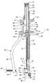
- FIG. 1is an illustration of the instrument of this invention being applied through an access opening in the face of a patient, as it would be for effecting a facelift in a patient.
- FIG. 3 ais a schematic view of a portion of the instrument of FIGS. 2 and 2 a , in which the suturing needle is in the “up” position, with the instrument is disposed between inner and outer surfaces between the skin and soft tissue of a patient, with vacuum applied to a cavity at the lower end of the instrument, drawing the skin subcutaneous tissue, fat, fascia or muscle (hereinafter abbreviated STFFM) into the cavity, and with a clamp applied to the outer surface of the skin also effecting engagement of the STFFM that is to be sutured into the cavity, and with the suturing needle in the “up” position.
- STFFMskin subcutaneous tissue, fat, fascia or muscle
- FIG. 3 cis an illustration like that of FIG. 3 b , but wherein the suturing needle is applied through the cavity, through the STFFM that is to be sutured, carrying the suture therethrough.
- FIG. 3 eis an illustration like that of FIG. 3 d , but wherein the clamp is removed, the suturing needle is in the “up” or withdrawn position, and wherein the sutured STFFM is shown attached to the cavity by means of the suture that has been hooked by the hook at the lower end of the instrument, such that, withdrawal of the instrument will withdraw the sutured STFFM in the direction of withdrawal.
- FIG. 5is a fragmentary view of an alternative embodiment to the instrument of FIG. 2 .
- FIG. 1wherein an instrument 10 is shown in an incision or opening 11 in the skin of a patient P, in accordance with this invention, wherein the instrument 10 is being used during a facelift operation.
- the instrument 10includes an insert 12 having first and second ends 13 and 14 , respectively. Above the upper or second end 14 of the insert 12 , there is a manually graspable portion of the instrument 10 , shown in the shape of a spool 15 , which portion 15 of the instrument remains outside the incision or access opening 11 of the patient, during use. Portions of the insert 12 near the lower end are shown broken away for the sake of clarity.
- the insert 12includes a hollow sleeve 16 extending downwardly from the lower end of the spool 15 .
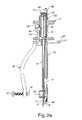
- FIG. 2 ait will be seen that the plunger 20 has been engaged at its upper end 21 and moved vertically downwardly, compressing the compression spring 45 , lowering the needle 17 to its downward position as shown in FIG. 2 a , with the lower end of the needle 17 and the suture 18 carried thereby in engagement through the cavity 24 , having passed through holes 27 , 28 (not shown in FIG. 2 a ), and with the sealing sleeve 30 being in sealed engagement against the exterior of the needle 24 .
- the hook 31 carried by the rod 32at the lower end of the insert 12 , is shown in FIG. 2 a as being in the hooked position, engaging the suture 18 upon the knob 33 at the upper end of the rod 32 having been manually engaged and turned in the direction of the arrow 60 shown in FIG. 2 a.
- FIG. 3 athe instrument 10 is shown, with the upper end, including the plunger 20 thereof being in phantom.
- the needle 17 which carries the suture 18is shown, fragmentally illustrated, poised to descend through holes 27 and 28 of the cavity 24 .
- the elastomeric sleeve 30is shown to the left of the cavity 24 , over which it is applied prior to insertion of the insert 12 into the incision 11 on the face of the patient P.
- the clamp device 35is shown in the outward position, with the clasp 43 unclasped from the keeper 44 , in order to facilitate insertion of the insert 12 into the skin opening 11 .
- the insert 12is shown inserted through the incision 11 , between outer and inner skin layers 65 , 66 respectively, with the right surface 67 of layer 66 representing the STFFM surface inside the patient P (such as inside the mouth of the patient), and with the left-most surface 68 of the skin layer 65 representing the outer surface of the face of the patient P.
- the elastomeric sleeve 30is shown applied over the cylindrical sleeve 26 , closing the holes 27 , 28 thereof.
- a clamping device 35is also provided.
- the clamping device 35is shown locked in the face-engaging position, with the clasp 43 locked against the keeper 44 , such that the threaded member 40 may be rightwardly urged, by manually engaging the knob 42 and rotating the threaded member 40 in the threaded lower end of the member 35 , such that its contact 41 engages the other surface 68 of the face, pushing the portion 70 of STFFM to the right thereof, into the cavity 24 , in airtight engagement against the left-most end of the elastomeric sleeve 30 .
- the knob 33is rotated in the direction of the arrow 60 , such that the rod 32 connected to the knob 33 is likewise rotated, to turn the hook 31 from the non-engaged position thereof illustrated in FIG. 3 c , to the suture-engaged position of FIG. 3 d , in which it engages the loop of suture 18 that extends below the sleeve 30 .
- the valve 20can be actuated from outside by the surgeon, such that the vacuum is released, and the device 35 may be released by release of the clasp 43 from the keeper 44 , and the suture-threaded portion of the STFFM 70 will remain connected to the lower end 13 of the insert, because the hook 31 remains in hooked relation to the loop of suture 18 shown beneath the sleeve 30 , extending through the holes 27 and 28 even as the needle 17 is withdrawn from the position of the needle 17 shown in FIG. 3 d , to its position as shown in FIG. 3 e .
- FIGS. 4 a – 4 dsome of the finer points with respect to the formation of a loop for the suture 18 , whereby the same may be engaged by a hook 31 , will now be discussed.
- the plunger 20is moved from its position shown if FIG. 4 a , to its position shown in FIG. 4 b , in which the STFFM layer 65 is pierced, and in which the plunger 20 is in its downward position, with the leaf spring 52 having returned to its full line position from the phantom position therefor E illustrated in FIG. 4 a.
- FIG. 4 cit will be seen that the thumb “T” of the surgeon has been removed, such that the compression spring 45 can urge the plunger 20 upwardly, such that the upper end of the protrusion 50 of the plunger 20 engages against the lower edge of the leaf spring 52 , which limits the upper movement of the plunger 20 to an amount “D” as shown in FIG. 4 c , whereby the needle 17 is carried upwardly by the plunger 20 the same amount “D”, as the needle 17 moves from its phantom position therefore illustrated in FIG. 4 c , to the full line position therefore illustrated in FIG. 4 c , such that the suture 18 which is frictionally engaged with the STFFM layer 65 and elastomeric sleeve 30 against upward movement with the needle 18 , forms a loop at its lower end as shown in FIG. 4 c.
- the vacuum lift feature of this inventionenables the surgeon to engage STFFM internally of the patient, at a location on the STFFM that optimizes the engagement of the same with the needle and thread, with the ability to vary the precise location of engagement of the STFFM with the needle and thread for optimizing the lift of the STFFM. Then, in the case of, for example, a facelift, if the optimum engagement of STFFM occurs on one side of the face, the same, or mirror imaged location on the opposite side of the face may be engaged, with precision, to balance the lift effects on each side.
- toothed forceps 124 , 125may be lowered between skin layers of a face or the like similarly to the manner in which the insert 12 of FIG. 2 is used.
- the skin-contacting contact 141will urge the skin 165 between the teeth 144 , 145 of the forceps 124 , 125 , an amount such that the STFFM becomes disposed between the needle openings 127 , 128 of the pincers 124 , 125 , such that downward movement of the needle 117 will carry the suture 118 through the openings 127 , 128 , whereupon the rod 113 that carries the hook 131 may be lowered to a position below the pincer 125 , such that the hook 131 can engage a loop of the suture 118 in a manner similar to that described above with respect to FIGS. 4 c and 4 d.
- rod 112 that carries the forceps 124 , 125may be unitary with the insert 110 , even though the components of FIG. 5 are only fragmentally illustrated for the sake of clarity.
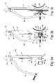
- FIG. 6it will be seen that another alternative embodiment of the invention is disclosed, in which the needle 217 is essentially U-shaped at its lower end, adapted for movement upwardly in the direction of the arrow 219 , to enter the openings 228 , 227 , such that the surgeon can manually recover the suture 218 with either a forceps (not shown), or a hook 231 carried by a rod 232 , by directly observing the suture endoscopically.
- a protective chamber or cap like that 19 (not shown) of FIG. 2may also be utilized to protect the needle and the patient at the lower end of the embodiment of FIG. 6 . Such a chamber or safety cap is not shown in FIG.
- FIG. 6for the sake of clarity of the rest of the items illustrated. It will further be understood that the various other components of the device of FIG. 6 , numbered in the 200 series, correspond to similarly numbered items in FIGS. 2 and 2 a carrying double digit numbers. Thus, item 212 of FIG. 6 corresponds to item 12 of FIGS. 2 and 2 a ; item 235 of FIG. 6 corresponds to item 35 of FIGS. 2 and 2 a ; chamber 224 of FIG. 6 corresponds to chamber 24 of FIGS. 2 and 2 a , etc., such that redundant explanation of the operation of similar components of FIG. 6 to those of FIGS. 2 and 2 a need not herein be repeated.
- the threaded member 40is shown by way of illustration only, in that any other contact member for engaging the outside surface of skin, to facilitate the placement of that portion of the STFFM that is to be sutured, may be effected.
- a device of the type 35 that is shown for carrying the threaded member 40may be of the type shown, various other techniques for engaging the outer surface 68 of skin may suffice.
- a clasp 43may be used for locking the device 35 in a skin-contacting position as shown in FIG. 3 d , any other form of locking device may likewise be utilized.
- an elastomeric cylindrical sealsuch as that 30 is shown for facilitating the maintenance of a vacuum around the outer surface of the needle 17 is shown as a preferred technique, various other vacuum-assuring techniques may alternatively be utilized.
- a hooksuch as that 31 , actuable from a member such as that 33 is described as a means for securing the sutured STFFM 70 to the lower end 13 of the insert, other securement means may likewise be utilized.
- the lever arrangement 54 and leaf spring 52is shown as a means for holding the plunger 20 in the “down” position, various other techniques could likewise be used.
- the spring 45is shown in the position for maintaining the plunger up, except when it is to be brought down against the force of the spring 45 , the converse arrangement could be used, in which the spring generally maintains the plunger downward, until it is pulled upwardly.
Landscapes
- Health & Medical Sciences (AREA)
- Life Sciences & Earth Sciences (AREA)
- Surgery (AREA)
- Heart & Thoracic Surgery (AREA)
- Engineering & Computer Science (AREA)
- Biomedical Technology (AREA)
- Nuclear Medicine, Radiotherapy & Molecular Imaging (AREA)
- Medical Informatics (AREA)
- Molecular Biology (AREA)
- Animal Behavior & Ethology (AREA)
- General Health & Medical Sciences (AREA)
- Public Health (AREA)
- Veterinary Medicine (AREA)
- Surgical Instruments (AREA)
Abstract
Description
Claims (21)
Priority Applications (9)
| Application Number | Priority Date | Filing Date | Title |
|---|---|---|---|
| US10/336,277US7060079B2 (en) | 2003-01-03 | 2003-01-03 | Surgical instrument for endoscopic suturing of deep subcutaneous tissue |
| AU2003300914AAU2003300914A1 (en) | 2003-01-03 | 2003-12-15 | Surgical instrument for endoscopic suturing of deep subcutaneous tissue |
| DE60336507TDE60336507D1 (en) | 2003-01-03 | 2003-12-15 | SURGICAL INSTRUMENT FOR THE ENDOSCOPIC SEAM OF A DEEP SUBCUTANEOUS TISSUE |
| EP03815208AEP1592351B1 (en) | 2003-01-03 | 2003-12-15 | Surgical instrument for endoscopic suturing of deep subcutaneous tissue |
| PCT/US2003/039749WO2004062466A2 (en) | 2003-01-03 | 2003-12-15 | Surgical instrument for endoscopic suturing of deep subcutaneous tissue |
| CA2523791ACA2523791C (en) | 2003-01-03 | 2003-12-15 | Surgical instrument for endoscopic suturing of deep subcutaneous tissue |
| AT03815208TATE502587T1 (en) | 2003-01-03 | 2003-12-15 | SURGICAL INSTRUMENT FOR ENDOSCOPIC SUTURE OF DEEP SUBCUTANEOUS TISSUE |
| US11/341,161US7780684B2 (en) | 2003-01-03 | 2006-01-27 | Surgical instrument for endoscopic suturing of deep subcutaneous tissue |
| US12/699,126US20100137888A1 (en) | 2003-01-03 | 2010-02-03 | Surgical Instrument for Endoscopic Suturing of Deep Subcutaneous Tissue |
Applications Claiming Priority (1)
| Application Number | Priority Date | Filing Date | Title |
|---|---|---|---|
| US10/336,277US7060079B2 (en) | 2003-01-03 | 2003-01-03 | Surgical instrument for endoscopic suturing of deep subcutaneous tissue |
Related Child Applications (1)
| Application Number | Title | Priority Date | Filing Date |
|---|---|---|---|
| US11/341,161ContinuationUS7780684B2 (en) | 2003-01-03 | 2006-01-27 | Surgical instrument for endoscopic suturing of deep subcutaneous tissue |
Publications (2)
| Publication Number | Publication Date |
|---|---|
| US20040133216A1 US20040133216A1 (en) | 2004-07-08 |
| US7060079B2true US7060079B2 (en) | 2006-06-13 |
Family
ID=32680976
Family Applications (2)
| Application Number | Title | Priority Date | Filing Date |
|---|---|---|---|
| US10/336,277Expired - LifetimeUS7060079B2 (en) | 2003-01-03 | 2003-01-03 | Surgical instrument for endoscopic suturing of deep subcutaneous tissue |
| US11/341,161Active2026-04-28US7780684B2 (en) | 2003-01-03 | 2006-01-27 | Surgical instrument for endoscopic suturing of deep subcutaneous tissue |
Family Applications After (1)
| Application Number | Title | Priority Date | Filing Date |
|---|---|---|---|
| US11/341,161Active2026-04-28US7780684B2 (en) | 2003-01-03 | 2006-01-27 | Surgical instrument for endoscopic suturing of deep subcutaneous tissue |
Country Status (7)
| Country | Link |
|---|---|
| US (2) | US7060079B2 (en) |
| EP (1) | EP1592351B1 (en) |
| AT (1) | ATE502587T1 (en) |
| AU (1) | AU2003300914A1 (en) |
| CA (1) | CA2523791C (en) |
| DE (1) | DE60336507D1 (en) |
| WO (1) | WO2004062466A2 (en) |
Cited By (19)
| Publication number | Priority date | Publication date | Assignee | Title |
|---|---|---|---|---|
| US20070255296A1 (en)* | 2006-04-26 | 2007-11-01 | Lsi Solutions, Inc. | Medical instrument to place a pursestring suture, open a hole and pass a guidewire |
| US20080132942A1 (en)* | 2006-12-04 | 2008-06-05 | Gregory Paul Mueller | Suture and method for using same |
| US20080132921A1 (en)* | 2006-12-04 | 2008-06-05 | Gregory Paul Mueller | Necklift procedure and instruments for performing same |
| US20080132946A1 (en)* | 2006-12-04 | 2008-06-05 | Gregory Paul Mueller | Skin port |
| US20080132931A1 (en)* | 2006-12-04 | 2008-06-05 | Gregory Paul Mueller | Skin puncturing device |
| US20090054911A1 (en)* | 2006-12-04 | 2009-02-26 | Gregory Mueller | Surgical threading device and method for using same |
| US20100137888A1 (en)* | 2003-01-03 | 2010-06-03 | Eye Plastic Surgery, Ltd. | Surgical Instrument for Endoscopic Suturing of Deep Subcutaneous Tissue |
| US20110034905A1 (en)* | 2009-08-05 | 2011-02-10 | Cucin Robert L | Method of and apparatus for treating abdominal obesity and metabolic syndrome in human patients |
| US7951157B2 (en) | 2000-05-19 | 2011-05-31 | C.R. Bard, Inc. | Tissue capturing and suturing device and method |
| US8075573B2 (en) | 2003-05-16 | 2011-12-13 | C.R. Bard, Inc. | Single intubation, multi-stitch endoscopic suturing system |
| US8465471B2 (en) | 2009-08-05 | 2013-06-18 | Rocin Laboratories, Inc. | Endoscopically-guided electro-cauterizing power-assisted fat aspiration system for aspirating visceral fat tissue within the abdomen of a patient |
| US8864777B2 (en) | 2011-01-28 | 2014-10-21 | Anchor Orthopedics Xt Inc. | Methods for facilitating tissue puncture |
| US8951271B2 (en) | 2006-12-04 | 2015-02-10 | Implicitcare, Llc | Surgical threading device and method for using same |
| US9033999B2 (en) | 2006-12-04 | 2015-05-19 | Implicitcare, Llc | Surgical threading device with removable suture |
| US10660637B2 (en) | 2018-04-06 | 2020-05-26 | Cypris Medical, Inc. | Suturing system |
| US10898181B2 (en) | 2017-03-17 | 2021-01-26 | Cypris Medical, Inc. | Suturing system |
| US11033261B2 (en) | 2018-05-31 | 2021-06-15 | Cypris Medical, Inc. | Suture system |
| US11701107B2 (en) | 2021-03-26 | 2023-07-18 | Tsymm Innovations Llc | Suturing device and clamp for use with same |
| US12137899B2 (en) | 2020-05-11 | 2024-11-12 | Cypris Medical, Inc. | Multiple suture placement system |
Families Citing this family (13)
| Publication number | Priority date | Publication date | Assignee | Title |
|---|---|---|---|---|
| AU2004229028B2 (en)* | 1999-10-21 | 2007-05-31 | Edwards Lifesciences Corporation | Minimally invasive mitral valve repair method and apparatus |
| US6985870B2 (en) | 2002-01-11 | 2006-01-10 | Baxter International Inc. | Medication delivery system |
| AU2003243219B2 (en) | 2003-05-09 | 2009-10-29 | Covidien Lp | Anastomotic staple with fluid dispensing capillary |
| US20060282097A1 (en) | 2005-06-13 | 2006-12-14 | Ortiz Mark S | Surgical suturing apparatus with a non-visible spectrum sensing member |
| US7615060B2 (en)* | 2005-06-13 | 2009-11-10 | Ethicon-Endo Surgery, Inc. | Endoscopic suturing device |
| US7365988B2 (en) | 2005-11-04 | 2008-04-29 | Graftech International Holdings Inc. | Cycling LED heat spreader |
| BRPI0814101A2 (en) | 2007-07-26 | 2015-02-03 | Alpha Scient Corp | APPARATUS AND METHOD FOR REMOVAL AND SUBCUTANTIALLY POSITIONING A FABRIC, LIFTING, AND, SUTURE |
| US9226748B2 (en) | 2007-07-26 | 2016-01-05 | Alpha Scientific Corporation | Surgical suturing device, method and tools used therewith |
| HRPK20070533B3 (en)* | 2007-11-21 | 2011-01-31 | Zelimir Obradovic | Instrument for intradermal suturing of surgical wounds |
| US9636110B2 (en) | 2013-03-13 | 2017-05-02 | Alpha Scientific Corporation | Structural support incorporating multiple strands |
| BR112015023550A2 (en) | 2013-03-15 | 2017-07-18 | Alpha Scient Corporation | coupling tool for capturing a suture or surgical thread, and tissue manipulation system |
| CN103565484A (en)* | 2013-08-24 | 2014-02-12 | 郑科 | Minz deep tissue suture method and minz deep tissue suture instrument |
| US10537322B2 (en)* | 2017-01-17 | 2020-01-21 | Ethicon Llc | Surgical suturing instrument cartridge with needle release feature |
Citations (11)
| Publication number | Priority date | Publication date | Assignee | Title |
|---|---|---|---|---|
| US4841888A (en)* | 1984-09-11 | 1989-06-27 | Mills Timothy N | Sewing machine |
| US5507754A (en)* | 1993-08-20 | 1996-04-16 | United States Surgical Corporation | Apparatus and method for applying and adjusting an anchoring device |
| US5549617A (en)* | 1993-08-20 | 1996-08-27 | United States Surgical Corporation | Apparatus and method for applying and adjusting an anchoring device |
| US5792153A (en)* | 1994-03-23 | 1998-08-11 | University College London | Sewing device |
| US5797927A (en)* | 1995-09-22 | 1998-08-25 | Yoon; Inbae | Combined tissue clamping and suturing instrument |
| US5871490A (en) | 1997-04-08 | 1999-02-16 | Ethicon Endo-Surgery, Inc. | Suture cartridge assembly for a surgical knot |
| US5947982A (en) | 1997-04-02 | 1999-09-07 | Smith & Nephew, Inc. | Suture-passing forceps |
| US5980538A (en) | 1997-09-09 | 1999-11-09 | Werner Fuchs | Surgical suturing instrument |
| US5984932A (en)* | 1996-11-27 | 1999-11-16 | Yoon; Inbae | Suturing instrument with one or more spreadable needle holders mounted for arcuate movement |
| US6036700A (en) | 1998-07-14 | 2000-03-14 | Ethicon Endo-Surgery, Inc. | Surgical anastomosis instrument |
| US6533796B1 (en)* | 2000-10-11 | 2003-03-18 | Lsi Solutions, Inc. | Loader for surgical suturing instrument |
Family Cites Families (2)
| Publication number | Priority date | Publication date | Assignee | Title |
|---|---|---|---|---|
| US5947700A (en)* | 1997-07-28 | 1999-09-07 | Mckain; Paul C. | Fluid vacuum safety device for fluid transfer systems in swimming pools |
| WO2001089370A2 (en)* | 2000-05-19 | 2001-11-29 | C.R. Bard, Inc. | Method of promoting tissue adhesion |
- 2003
- 2003-01-03USUS10/336,277patent/US7060079B2/ennot_activeExpired - Lifetime
- 2003-12-15EPEP03815208Apatent/EP1592351B1/ennot_activeExpired - Lifetime
- 2003-12-15ATAT03815208Tpatent/ATE502587T1/ennot_activeIP Right Cessation
- 2003-12-15CACA2523791Apatent/CA2523791C/ennot_activeExpired - Lifetime
- 2003-12-15WOPCT/US2003/039749patent/WO2004062466A2/ennot_activeApplication Discontinuation
- 2003-12-15DEDE60336507Tpatent/DE60336507D1/ennot_activeExpired - Lifetime
- 2003-12-15AUAU2003300914Apatent/AU2003300914A1/ennot_activeAbandoned
- 2006
- 2006-01-27USUS11/341,161patent/US7780684B2/enactiveActive
Patent Citations (11)
| Publication number | Priority date | Publication date | Assignee | Title |
|---|---|---|---|---|
| US4841888A (en)* | 1984-09-11 | 1989-06-27 | Mills Timothy N | Sewing machine |
| US5507754A (en)* | 1993-08-20 | 1996-04-16 | United States Surgical Corporation | Apparatus and method for applying and adjusting an anchoring device |
| US5549617A (en)* | 1993-08-20 | 1996-08-27 | United States Surgical Corporation | Apparatus and method for applying and adjusting an anchoring device |
| US5792153A (en)* | 1994-03-23 | 1998-08-11 | University College London | Sewing device |
| US5797927A (en)* | 1995-09-22 | 1998-08-25 | Yoon; Inbae | Combined tissue clamping and suturing instrument |
| US5984932A (en)* | 1996-11-27 | 1999-11-16 | Yoon; Inbae | Suturing instrument with one or more spreadable needle holders mounted for arcuate movement |
| US5947982A (en) | 1997-04-02 | 1999-09-07 | Smith & Nephew, Inc. | Suture-passing forceps |
| US5871490A (en) | 1997-04-08 | 1999-02-16 | Ethicon Endo-Surgery, Inc. | Suture cartridge assembly for a surgical knot |
| US5980538A (en) | 1997-09-09 | 1999-11-09 | Werner Fuchs | Surgical suturing instrument |
| US6036700A (en) | 1998-07-14 | 2000-03-14 | Ethicon Endo-Surgery, Inc. | Surgical anastomosis instrument |
| US6533796B1 (en)* | 2000-10-11 | 2003-03-18 | Lsi Solutions, Inc. | Loader for surgical suturing instrument |
Cited By (49)
| Publication number | Priority date | Publication date | Assignee | Title |
|---|---|---|---|---|
| US7951157B2 (en) | 2000-05-19 | 2011-05-31 | C.R. Bard, Inc. | Tissue capturing and suturing device and method |
| US20100137888A1 (en)* | 2003-01-03 | 2010-06-03 | Eye Plastic Surgery, Ltd. | Surgical Instrument for Endoscopic Suturing of Deep Subcutaneous Tissue |
| US8075573B2 (en) | 2003-05-16 | 2011-12-13 | C.R. Bard, Inc. | Single intubation, multi-stitch endoscopic suturing system |
| US20070255296A1 (en)* | 2006-04-26 | 2007-11-01 | Lsi Solutions, Inc. | Medical instrument to place a pursestring suture, open a hole and pass a guidewire |
| US20100211082A1 (en)* | 2006-04-26 | 2010-08-19 | Lsi Solutions, Inc. | Medical instrument to place a pursestring suture, open a hole and pass a guidewire |
| US7731727B2 (en)* | 2006-04-26 | 2010-06-08 | Lsi Solutions, Inc. | Medical instrument to place a pursestring suture, open a hole and pass a guidewire |
| US7914191B2 (en) | 2006-12-04 | 2011-03-29 | Implicitcare, Llc | Surgical instrument docking device |
| US20080132942A1 (en)* | 2006-12-04 | 2008-06-05 | Gregory Paul Mueller | Suture and method for using same |
| US20080131659A1 (en)* | 2006-12-04 | 2008-06-05 | Gregory Paul Mueller | Laminated surgical tape and method for using same |
| US20080132931A1 (en)* | 2006-12-04 | 2008-06-05 | Gregory Paul Mueller | Skin puncturing device |
| US20080132947A1 (en)* | 2006-12-04 | 2008-06-05 | Gregory Paul Mueller | Surgical threading device and method for using same |
| US20080132917A1 (en)* | 2006-12-04 | 2008-06-05 | Gregory Paul Mueller | Surgical instrument docking device |
| US20080132918A1 (en)* | 2006-12-04 | 2008-06-05 | Gregory Paul Mueller | Surgical instrument docking device |
| US20080132905A1 (en)* | 2006-12-04 | 2008-06-05 | Gregory Paul Mueller | Surgical clearing device and method for using same |
| US20090054911A1 (en)* | 2006-12-04 | 2009-02-26 | Gregory Mueller | Surgical threading device and method for using same |
| US7566340B2 (en) | 2006-12-04 | 2009-07-28 | Implicitcare, Llc | Surgical threading device and method for using same |
| US20090248072A1 (en)* | 2006-12-04 | 2009-10-01 | Implicitcare, Llc | Surgical threading device |
| US20080132945A1 (en)* | 2006-12-04 | 2008-06-05 | Gregory Paul Mueller | Necklift procedure and instruments for performing same |
| US20080132920A1 (en)* | 2006-12-04 | 2008-06-05 | Gregory Paul Mueller | Surgical instruments for positioning suture knots |
| US7740647B2 (en) | 2006-12-04 | 2010-06-22 | Implicitcare, Llc | Necklift procedure and instruments for performing same |
| US20080132916A1 (en)* | 2006-12-04 | 2008-06-05 | Gregory Paul Mueller | Surgical threading device and method for using same |
| US7833233B2 (en) | 2006-12-04 | 2010-11-16 | Implicitcare, Llc | Surgical threading device and method for using same |
| US7842052B2 (en) | 2006-12-04 | 2010-11-30 | Implicitcare, Llc | Necklift procedure and instruments for performing same |
| US9033999B2 (en) | 2006-12-04 | 2015-05-19 | Implicitcare, Llc | Surgical threading device with removable suture |
| US20080132907A1 (en)* | 2006-12-04 | 2008-06-05 | Gregory Paul Mueller | Surgical tape and method for using same |
| US20080132921A1 (en)* | 2006-12-04 | 2008-06-05 | Gregory Paul Mueller | Necklift procedure and instruments for performing same |
| US8025671B2 (en) | 2006-12-04 | 2011-09-27 | Implicitcare, Llc | Surgical threading device and method for using same |
| US20080132946A1 (en)* | 2006-12-04 | 2008-06-05 | Gregory Paul Mueller | Skin port |
| US8951271B2 (en) | 2006-12-04 | 2015-02-10 | Implicitcare, Llc | Surgical threading device and method for using same |
| US8826914B2 (en) | 2006-12-04 | 2014-09-09 | Implicitcare, Llc | Surgical tape and method for using same |
| US11259862B2 (en) | 2009-08-05 | 2022-03-01 | Rocin Laboratories, Inc. | Coaxial-driven tissue aspiration instrument system |
| US8348929B2 (en) | 2009-08-05 | 2013-01-08 | Rocin Laboratories, Inc. | Endoscopically-guided tissue aspiration system for safely removing fat tissue from a patient |
| US20110034905A1 (en)* | 2009-08-05 | 2011-02-10 | Cucin Robert L | Method of and apparatus for treating abdominal obesity and metabolic syndrome in human patients |
| US9833279B2 (en) | 2009-08-05 | 2017-12-05 | Rocin Laboratories, Inc. | Twin-cannula tissue aspiration instrument system |
| US9925314B2 (en) | 2009-08-05 | 2018-03-27 | Rocin Laboratories, Inc. | Method of performing intra-abdominal tissue aspiration to ameliorate the metabolic syndrome, or abdominal obesity |
| US12178494B2 (en) | 2009-08-05 | 2024-12-31 | Rocin Laboratories, Inc | Laparoscopic-based method of safely removing visceral fat tissue deposits from within the mesenteric region of a human patient suffering from metabolic syndrome |
| US12171482B2 (en) | 2009-08-05 | 2024-12-24 | Rocin Laboratories, Inc. | Bariatric surgery operating room with a laparoscopic-based visceral fat tissue aspiration system configured and operational for treating metabolic syndrome in human patients on an ambulatory basis |
| US8465471B2 (en) | 2009-08-05 | 2013-06-18 | Rocin Laboratories, Inc. | Endoscopically-guided electro-cauterizing power-assisted fat aspiration system for aspirating visceral fat tissue within the abdomen of a patient |
| US8864777B2 (en) | 2011-01-28 | 2014-10-21 | Anchor Orthopedics Xt Inc. | Methods for facilitating tissue puncture |
| US12053173B2 (en) | 2017-03-17 | 2024-08-06 | Cypris Medical, Inc. | Suturing system |
| US10898181B2 (en) | 2017-03-17 | 2021-01-26 | Cypris Medical, Inc. | Suturing system |
| US11103236B2 (en) | 2018-04-06 | 2021-08-31 | Cypris Medical, Inc. | Suturing system |
| US12082804B2 (en) | 2018-04-06 | 2024-09-10 | Cypris Medical, Inc. | Suturing system |
| US10660637B2 (en) | 2018-04-06 | 2020-05-26 | Cypris Medical, Inc. | Suturing system |
| US11033261B2 (en) | 2018-05-31 | 2021-06-15 | Cypris Medical, Inc. | Suture system |
| US12137900B2 (en) | 2018-05-31 | 2024-11-12 | Cypris Medical, Inc. | Suture system |
| US12137899B2 (en) | 2020-05-11 | 2024-11-12 | Cypris Medical, Inc. | Multiple suture placement system |
| US11701107B2 (en) | 2021-03-26 | 2023-07-18 | Tsymm Innovations Llc | Suturing device and clamp for use with same |
| US12383257B2 (en) | 2021-03-26 | 2025-08-12 | Tsymm Innovations Llc | Suturing device and clamp for use with same |
Also Published As
| Publication number | Publication date |
|---|---|
| ATE502587T1 (en) | 2011-04-15 |
| WO2004062466A3 (en) | 2005-03-03 |
| US20060149298A1 (en) | 2006-07-06 |
| EP1592351A4 (en) | 2009-01-21 |
| AU2003300914A8 (en) | 2004-08-10 |
| US7780684B2 (en) | 2010-08-24 |
| AU2003300914A1 (en) | 2004-08-10 |
| EP1592351A2 (en) | 2005-11-09 |
| US20040133216A1 (en) | 2004-07-08 |
| WO2004062466A2 (en) | 2004-07-29 |
| EP1592351B1 (en) | 2011-03-23 |
| CA2523791A1 (en) | 2004-07-29 |
| DE60336507D1 (en) | 2011-05-05 |
| CA2523791C (en) | 2012-02-07 |
Similar Documents
| Publication | Publication Date | Title |
|---|---|---|
| US7780684B2 (en) | Surgical instrument for endoscopic suturing of deep subcutaneous tissue | |
| US20100137888A1 (en) | Surgical Instrument for Endoscopic Suturing of Deep Subcutaneous Tissue | |
| US5281237A (en) | Surgical stitching device and method of use | |
| US5336239A (en) | Surgical needle | |
| JP4038524B2 (en) | Medical instrument and internal organ fixing method | |
| US5843099A (en) | Single system ligature carrier and tissue clamp for sacrospinous colpopexy | |
| US8333774B2 (en) | Suturing instrument with needle dock | |
| JP4767505B2 (en) | Suture threading device and method for threading suture through tissue | |
| US6074403A (en) | Suture retriever | |
| US5320632A (en) | Surgical suturing apparatus | |
| US9402986B2 (en) | Method for hernia repair | |
| US8082925B2 (en) | Transvaginal tube as an aid to laparoscopic surgery | |
| US20050043746A1 (en) | Methods and instruments for closing laparoscopic trocar puncture wounds | |
| US20140296881A1 (en) | Instruments for delivering transfascial sutures, transfascial suture assemblies and methods of transfascial suturing | |
| US9579472B2 (en) | Veress needle with illuminated guidance and suturing capability | |
| US20100191260A1 (en) | Veress needle with illuminated guidance and suturing capability | |
| US9895146B1 (en) | Wound closure device | |
| JP2010534510A (en) | Surgical suture device, method, and tool for use therewith | |
| US12383257B2 (en) | Suturing device and clamp for use with same | |
| US20090018580A1 (en) | Surgical Method and Apparatus | |
| US20200046339A1 (en) | Three-in-one suturing device for closing cannula hole | |
| KR20200132514A (en) | Closure Device built in Trocar | |
| CN217066460U (en) | Puncture thread hooking device |
Legal Events
| Date | Code | Title | Description |
|---|---|---|---|
| AS | Assignment | Owner name:EYE PLASTIC SURGERY, LTD., PENNSYLVANIA Free format text:ASSIGNMENT OF ASSIGNORS INTEREST;ASSIGNORS:WULC, ALLAN E.;WULC, STANLEY S.;REEL/FRAME:013646/0393 Effective date:20021229 | |
| STCF | Information on status: patent grant | Free format text:PATENTED CASE | |
| CC | Certificate of correction | ||
| AS | Assignment | Owner name:WULC, ALLAN E., PENNSYLVANIA Free format text:ASSIGNMENT OF ASSIGNORS INTEREST;ASSIGNOR:EYE PLASTIC SURGERY, LTD.;REEL/FRAME:022928/0939 Effective date:20090703 | |
| FPAY | Fee payment | Year of fee payment:4 | |
| AS | Assignment | Owner name:EYE PLASTIC SURGERY, P.C., PENNSYLVANIA Free format text:CORRECTIVE ASSIGNMENT TO CORRECT THE NAME OF THE ASSIGNEE FROM EYE PLASTIC SURGERY, LTD., TO EYE PLASTIC SURGERY, P.C. PREVIOUSLY RECORDED ON REEL 013646 FRAME 0393. ASSIGNOR(S) HEREBY CONFIRMS THE ASSIGNMENT TO EYE PLASTIC SURGERY, P.C.;ASSIGNORS:WULC, ALLAN E.;WULC, STANLEY S.;SIGNING DATES FROM 20100604 TO 20100607;REEL/FRAME:024794/0476 | |
| AS | Assignment | Owner name:APOGEE AESTHETICS, LLC, PENNSYLVANIA Free format text:ASSIGNMENT OF ASSIGNORS INTEREST;ASSIGNOR:WULC, ALLAN E.;REEL/FRAME:025192/0868 Effective date:20101008 | |
| AS | Assignment | Owner name:WULC, ALLAN E., PENNSYLVANIA Free format text:CORRECTIVE ASSIGNMENT TO CORRECT THE NAME OF THE ASSIGNOR, PREVIOUSLY RECORDED ON REEL 022928 FRAME 0939. ASSIGNOR(S) HEREBY CONFIRMS THE ASSIGNMENT;ASSIGNOR:EYE PLASTIC SURGERY, P.C.;REEL/FRAME:025300/0375 Effective date:20090703 | |
| FPAY | Fee payment | Year of fee payment:8 | |
| FPAY | Fee payment | Year of fee payment:12 |