US7060068B2 - Vertebrae fastener placement guide - Google Patents
Vertebrae fastener placement guideDownload PDFInfo
- Publication number
- US7060068B2 US7060068B2US10/748,120US74812003AUS7060068B2US 7060068 B2US7060068 B2US 7060068B2US 74812003 AUS74812003 AUS 74812003AUS 7060068 B2US7060068 B2US 7060068B2
- Authority
- US
- United States
- Prior art keywords
- guide
- bone portion
- vertebral bone
- handle
- members
- Prior art date
- Legal status (The legal status is an assumption and is not a legal conclusion. Google has not performed a legal analysis and makes no representation as to the accuracy of the status listed.)
- Expired - Fee Related, expires
Links
- 210000000988bone and boneAnatomy0.000claimsabstractdescription44
- 230000007246mechanismEffects0.000claimsabstractdescription33
- 210000003484anatomyAnatomy0.000claimsdescription2
- 238000010168coupling processMethods0.000description18
- 238000005859coupling reactionMethods0.000description18
- 230000008878couplingEffects0.000description14
- 238000000034methodMethods0.000description13
- 238000001356surgical procedureMethods0.000description5
- 230000008569processEffects0.000description4
- 210000004247handAnatomy0.000description3
- 230000006378damageEffects0.000description2
- 230000006837decompressionEffects0.000description2
- 238000003780insertionMethods0.000description2
- 230000037431insertionEffects0.000description2
- 238000012986modificationMethods0.000description2
- 230000004048modificationEffects0.000description2
- 208000010392Bone FracturesDiseases0.000description1
- 208000003618Intervertebral Disc DisplacementDiseases0.000description1
- 208000027418Wounds and injuryDiseases0.000description1
- 230000002159abnormal effectEffects0.000description1
- 230000004075alterationEffects0.000description1
- 238000005553drillingMethods0.000description1
- 230000000694effectsEffects0.000description1
- 230000004927fusionEffects0.000description1
- 230000035876healingEffects0.000description1
- 208000014674injuryDiseases0.000description1
- 230000001788irregularEffects0.000description1
- 206010025005lumbar spinal stenosisDiseases0.000description1
- 230000036244malformationEffects0.000description1
- 230000000399orthopedic effectEffects0.000description1
- 230000001737promoting effectEffects0.000description1
- 206010041569spinal fractureDiseases0.000description1
- 208000005198spinal stenosisDiseases0.000description1
- 238000002560therapeutic procedureMethods0.000description1
- 210000001519tissueAnatomy0.000description1
- 210000000707wristAnatomy0.000description1
Images


Classifications
- A—HUMAN NECESSITIES
- A61—MEDICAL OR VETERINARY SCIENCE; HYGIENE
- A61B—DIAGNOSIS; SURGERY; IDENTIFICATION
- A61B17/00—Surgical instruments, devices or methods
- A61B17/16—Instruments for performing osteoclasis; Drills or chisels for bones; Trepans
- A61B17/1662—Instruments for performing osteoclasis; Drills or chisels for bones; Trepans for particular parts of the body
- A61B17/1671—Instruments for performing osteoclasis; Drills or chisels for bones; Trepans for particular parts of the body for the spine
- A—HUMAN NECESSITIES
- A61—MEDICAL OR VETERINARY SCIENCE; HYGIENE
- A61B—DIAGNOSIS; SURGERY; IDENTIFICATION
- A61B17/00—Surgical instruments, devices or methods
- A61B17/16—Instruments for performing osteoclasis; Drills or chisels for bones; Trepans
- A61B17/1613—Component parts
- A61B17/1615—Drill bits, i.e. rotating tools extending from a handpiece to contact the worked material
- A—HUMAN NECESSITIES
- A61—MEDICAL OR VETERINARY SCIENCE; HYGIENE
- A61B—DIAGNOSIS; SURGERY; IDENTIFICATION
- A61B17/00—Surgical instruments, devices or methods
- A61B17/16—Instruments for performing osteoclasis; Drills or chisels for bones; Trepans
- A61B17/1655—Instruments for performing osteoclasis; Drills or chisels for bones; Trepans for tapping
- A—HUMAN NECESSITIES
- A61—MEDICAL OR VETERINARY SCIENCE; HYGIENE
- A61B—DIAGNOSIS; SURGERY; IDENTIFICATION
- A61B17/00—Surgical instruments, devices or methods
- A61B17/16—Instruments for performing osteoclasis; Drills or chisels for bones; Trepans
- A61B17/17—Guides or aligning means for drills, mills, pins or wires
- A61B17/1739—Guides or aligning means for drills, mills, pins or wires specially adapted for particular parts of the body
- A61B17/1757—Guides or aligning means for drills, mills, pins or wires specially adapted for particular parts of the body for the spine
- A—HUMAN NECESSITIES
- A61—MEDICAL OR VETERINARY SCIENCE; HYGIENE
- A61B—DIAGNOSIS; SURGERY; IDENTIFICATION
- A61B17/00—Surgical instruments, devices or methods
- A61B17/56—Surgical instruments or methods for treatment of bones or joints; Devices specially adapted therefor
- A61B17/58—Surgical instruments or methods for treatment of bones or joints; Devices specially adapted therefor for osteosynthesis, e.g. bone plates, screws or setting implements
- A61B17/88—Osteosynthesis instruments; Methods or means for implanting or extracting internal or external fixation devices
- A61B17/8875—Screwdrivers, spanners or wrenches
- A61B17/8886—Screwdrivers, spanners or wrenches holding the screw head
- A61B17/8891—Screwdrivers, spanners or wrenches holding the screw head at its periphery
- A—HUMAN NECESSITIES
- A61—MEDICAL OR VETERINARY SCIENCE; HYGIENE
- A61B—DIAGNOSIS; SURGERY; IDENTIFICATION
- A61B17/00—Surgical instruments, devices or methods
- A61B2017/0046—Surgical instruments, devices or methods with a releasable handle; with handle and operating part separable
- A—HUMAN NECESSITIES
- A61—MEDICAL OR VETERINARY SCIENCE; HYGIENE
- A61B—DIAGNOSIS; SURGERY; IDENTIFICATION
- A61B90/00—Instruments, implements or accessories specially adapted for surgery or diagnosis and not covered by any of the groups A61B1/00 - A61B50/00, e.g. for luxation treatment or for protecting wound edges
- A61B90/06—Measuring instruments not otherwise provided for
- A61B2090/062—Measuring instruments not otherwise provided for penetration depth
Definitions
- the present inventiongenerally relates to fastener guides, and more specifically, but not exclusively, concerns an apparatus and method for fixing a portion of a spine with a fastener.
- the screwIn the translaminar procedure, the screw is passed through the facets and laminae of adjacent vertebrae in order to fix the adjacent vertebrae together.
- the procedureis further complicated by the tight operating space. Only a limited number of hands can have access to the tight operating space. Complications, such as spinal damage, can also ensue if a screw with an improper length is used to fix the adjacent vertebrae together. Therefore, there has been a long felt need for a device to provide precise hands free guidance of screws through the spine and that allows a surgeon to see the exact trajectory and required length of a screw prior to fastening the vertebrae together.
- One form of the present inventionis a unique fastener placement guide. Another form concerns a unique method for fixing two vertebrae together.
- a further form of the present inventionis directed to a unique apparatus for guiding a fastener that fastens a first vertebral bone portion with a second vertebral bone portion.
- the apparatusincludes a first member having a first guide adapted to contact the first vertebral bone portion.
- a second memberhas a second guide that is aligned with the first guide and adapted to contact the second vertebral bone portion.
- a clamping mechanismis provided between the first and second members to clamp the first guide and the second guide to the respective bone portions.
- the first and second guidesindicate fastener alignment.
- a fastener placement apparatushas a first member with a first guide, a second member with a second guide aligned with the first guide, and a clamping mechanism to clamp the members together.
- the first and second guidesare aligned along two vertebral bone portions.
- the two bone portionsare clamped together with the first and second members.
- the two bone portionsare fastened together with a fastener that is in alignment with the first and second guides.
- FIG. 1is a perspective view of a screw placement guide according to one embodiment of the present invention.
- FIG. 2is a side view of the screw placement guide of FIG. 1 without a handle and a driver.
- FIG. 3is an end view of the screw placement guide of FIG. 2 .
- FIG. 4is a top view of the screw placement guide of FIG. 2 .
- FIG. 5is a side view of one member shown in FIG. 1 .
- FIG. 6is a side view of another member shown in FIG. 1 .
- FIG. 7is an end view of the first member shown in FIG. 6 .
- FIG. 8is a partial cross-sectional view of a portion of the first member shown in FIG. 6 and taken at line 8 — 8 in FIG. 7 and viewed in the direction of the arrows.
- FIG. 9is a side view of the driver shown in FIG. 1 .
- FIG. 10is a perspective view of a screw placement guide according to another embodiment of the present invention.
- FIG. 11is a side view of one member shown in FIG. 10 .
- FIG. 12is an end view of another member shown in FIG. 10 .
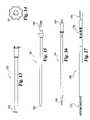
- FIG. 13is a side view of a guide tube.
- FIG. 14is an end view of the guide tube shown in FIG. 13 .
- FIG. 15is a side view of a trocar.
- FIG. 16is a side view of an awl.
- FIG. 17is a side view of a drill bit.
- FIG. 18is a side view of a screwdriver.
- FIG. 19is an enlarged side view of one end of the screwdriver shown in FIG. 18 .
- FIG. 20is an enlarged side view of an end of a screwdriver according to another embodiment.
- FIG. 21is a top view of the screw placement guide of FIG. 1 clamped to adjacent vertebrae.
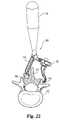
- FIG. 22is a partial cross-sectional view of a vertebra showing the screw placement guide of FIG. 1 clamped to adjacent vertebrae.
- FIG. 23is a side view of the screw placement guide of FIG. 1 clamped to adjacent vertebrae.
- FIG. 24is a partial cross-sectional view through a vertebra showing the screw placement guide of FIG. 1 along with a driver.
- FIG. 25is a top view of a treatment site incision opening in a prone patient shown fragmentarily, and showing the screw placement guide clamped to the adjacent vertebrae along with a guide tube and trocar inserted through a second percutaneous incision in the patient.
- FIG. 26is a partial cross-sectional view of a vertebra showing the screw placement guide along with the guide tube and trocar.
- FIG. 27is a partial cross-sectional view of a vertebra, showing an awl ready for marking a starting point on the vertebra.
- FIG. 28is a partial cross-sectional view of a drill bit inside the vertebra.
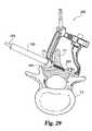
- FIG. 29is a partial cross-sectional view of a screw threaded into the vertebra.
- FIG. 30is an exploded-perspective view of a screw placement guide according to another embodiment of the present invention.
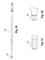
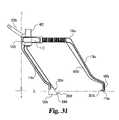
- FIG. 31is a side view of the screw placement guide shown in FIG. 30 without a handle and a driver.
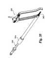
- FIG. 32is an exploded perspective view of the screw placement guide shown in FIG. 31 .
- FIG. 33is an exploded perspective view of a screw placement guide according to a further embodiment of the present invention.
- FIG. 34is a side view of a tap.
- FIG. 35is a perspective view of the tap of FIG. 34 inserted in a guide tube that is coupled to the screw placement guide of FIG. 30 .
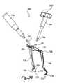
- FIG. 1shows a perspective view of a screw placement guide 100 according to one embodiment of the present invention.
- the placement guide 100includes a first (driving) member 102 , and a second (clamping) member 104 .
- a clamping mechanism 106moveably couples the first member 102 with the second member 104 .
- a driver 108is removably coupled to clamping mechanism 106
- a handle 110is removably coupled to a handle coupling member 202 that extends from the second member 104 ( FIG. 2 ).
- Driver 108 and handle 110can be removed from guide 100 in order to reduce obstructions during surgery. It should be appreciated, however, that driver 108 and handle 110 can also be permanently attached to guide 100 .
- a locking mechanism 112is provided on the first member 102 .
- Driver 108is used to drive the clamping mechanism 106 in order to clamp the members 102 and 104 together.
- Locking mechanism 112is used to lock the relative positions between the members 102 and 104 .
- First member 102has a first support arm 114 that supports an arcuate guide member 116 .
- the arcuate cylindrical shape of guide 116helps to minimize the size of the incision required in order to locate guide 116 .
- Second member 104includes a support arm 118 and a cylindrical guide member 120 .
- Cylindrical guide member 120is adapted to receive a guide tube.
- Guide 120has a bore 122 defined therein.
- Bore 122has a conical entry surface 124 that is adapted to receive a guide tube.
- guides 116 and 120are aligned along longitudinal axis L. As shown in FIG. 3 , the guides 116 and 120 are also aligned along transverse axis T. During surgery, this alignment of guides 116 and 120 along both the longitudinal L and transverse T axes is used to indicate the alignment of a screw that is to be fastened through screw placement guide 100 .
- Clamping mechanism 106includes a pinion 402 that is received within first member 102 .
- Pinion 402has a driver engagement recess 404 , which is adapted to be engaged and rotated by driver 108 .
- Locking mechanism 112includes a locking lever 406 pivotally mounted to first member 102 by pin 408 .
- Lever 406further has a rack-engaging portion 410 , which is adapted to lock against second member 104 .
- Lever 406is spring biased to lock first and second members 102 , 104 into position. When lever 406 is pivoted in direction D, second member 104 is unlocked so that second member 104 can be moved by clamping mechanism 106 .
- Locking lever 406can also include a spring for biasing lever 406 to the locked position.
- Second member 104further has fastener length markings 412 that indicate the length of the required fastener.
- Second member 104has a clamping arm 502 that is coupled to clamping mechanism 106 on the first member 102 .
- Arm 502has a gear tooth rack portion 504 that engages pinion gear 402 in clamping mechanism 106 .
- Rack portion 504along with pinion gear 402 form a rack and pinion mechanism that is used to generate a clamping motion to clamp an object or objects between the first member 102 and second member 104 .
- guide 120further includes a conical outer surface 506 and a bone engaging surface 508 at an end. Bone engaging surface 508 has serrations 510 , which minimize slippage of the bone engaging surface 508 against bone.
- the conical shape of outer surface 506allows guide 120 to have a sharp bone engaging surface 508 in order to dig into bone.
- first member 102includes a lever mounting portion 602 at which locking lever 406 is pinned to first member 102 . Further, first member 102 has a lever receiving opening 603 through which rack engaging portion 410 of lever 406 is received and engages rack portion 504 of second member 104 .
- Support arm 114is shaped so that the size of an incision in a patient can be minimized. As shown, support arm 114 has a substantially straight portion 604 , an angled portion 606 , and a guide connecting portion 608 .
- Guide 116has a semi-cylindrical shape in order to allow guide 116 to engage a vertebra in a narrow area such as between facet and transverse process. Guide 116 includes a semi-conical portion 610 , and a vertebra engaging end 612 with serrations 614 . Conical portion 610 and serrations 614 help to minimize slippage of guide 116 against bone.
- First member 102 in FIG. 7further includes a clamping arm receiving aperture 702 in which clamping arm 502 of the second member 104 is received.
- An enlarged cross-sectional view taken at line 8 — 8 in FIG. 7 showing a portion of clamping mechanism 106is shown in FIG. 8 .
- First member 102has a pinion receiving hole 802 defined therein. Hole 802 is adapted to receive pinion 402 .
- hole 802includes a wide cylindrical portion 804 and a narrow cylindrical portion 806 .
- a ratchet connector (screw) 808is coupled to cylindrical portion 804 in order to secure the pinion 402 in hole 802 .
- Pinion 402has teeth 810 that engage the teeth of rack portion 504 of second member 104 .
- First member 102further has a spring cavity 812 that receives bias coil spring 814 . Bias spring 814 biases lever 406 into the locked position.
- Driver 108includes a handle portion 902 , a connector 904 coupled to handle portion 902 , and a pinion engaging portion 906 coupled to connector 904 .
- Pinion engaging portion 906is coupled to driver engagement recess 404 of pinion 402 .
- pinion-engaging portion 906has a hexagonal cross-sectional shape. It should be appreciated that pinion-engaging portion 906 can have other generally known cross-sectional shapes.
- handle portion 902has knurling 908 .
- the present inventioncan include other types of drivers that are generally known by those skilled in the art. For example, instead of a manual driver, an automatic driver can be used.
- FIG. 10A screw placement guide 1000 according to another embodiment of the present invention is shown in FIG. 10 .
- handle 110is coupled to first member 102 a instead of second member 104 a .
- Driver 108 ahas an elliptical shaped handle portion 1002 .
- second member 104 adoes not include handle coupling member 202 .
- first member 102 ahas a handle-coupling member 202 a .
- handle-coupling member 202 ais coupled to first member 102 a at an angle with respect to support arm 114 .
- handle-coupling member 202 along with handle 110are oriented at an angle so as to not interfere with rotation of driver 108 a and to relieve stress in a wrist of a surgeon.
- a guide tube 1300has a coupling end 1302 adapted to couple into guide 120 of the second member 104 or 104 a .
- Guide tube 1300has a hole 1402 of which is adapted to receive instruments.
- One such type of instrumentis a trocar 1500 , which is shown in FIG. 15 .
- Trocar 1500has a pointed end 1502 which aids during insertion.
- Trocar 1500further includes a coupling end 1504 adapted to couple to a handle and/or other types of generally known mechanisms.
- FIGS. 16–20Other types of instruments that can also be inserted into guide tube 1300 are shown in FIGS. 16–20 .
- Awl 1600includes a pointed end 1602 and a coupling end 1604 that is adapted to couple to a handle and/or other types of generally known mechanisms.
- drill bit 1700includes a cutting portion 1702 , a drill engaging portion 1704 , and depth markings 1706 .
- a screwdriver 1800according to one embodiment is shown in FIG. 18 .
- Screwdriver, 1800has a screw-engaging portion 1802 that is adapted to couple to a screw.
- An enlarged view of screw coupling portion 1802is shown in FIG. 19 .
- screw-coupling portion 1802 in one embodimenthas a “self-retaining configuration” that prevents slippage of the screwdriver from a screw.
- a coupling portion 2002 according to another embodimenthas a hexagonal cross-sectional shape with straight walls that couple to a screw.
- FIGS. 21–29A method for fixing adjacent vertebrae according to one embodiment of the present invention will now be described with reference to FIGS. 21–29 .
- screw placement guide 100can be used to fasten together a single fractured vertebra.
- other types of generally known fasteners, besides screws,can be used in conjunction with placement guides 100 and 1000 in order to fasten vertebral bone portions together.
- screw placement guide 100is aligned along adjacent vertebrae V 1 and V 2 .
- Arcuate guide 116allows guide 100 to couple to irregular shaped portions of vertebra V 2 , such as between facet and transverse process. Further, the arcuate shape of guide 116 reduces the amount of tissue that needs to be cut and moved.
- Arcuate guide 116is positioned on vertebra V 2 at a desired fastener exit point.
- Guide 120is then positioned at a desired fastener entry point on vertebra V 1 .
- Driver 108 in FIG. 24is coupled to the socket of pinion 402 of clamping mechanism 106 in order to clamp the guides 116 and 120 to the vertebrae V 1 and V 2 .
- screw placement guide 100Once screw placement guide 100 is properly positioned, driver 108 is rotated and drives clamping mechanism 106 in order to clamp guides 116 and 120 of screw placement guide 100 to the vertebrae V 2 and V 1 , respectively.
- Locking mechanism 112locks members 102 and 104 into position relative to each other.
- Guides 116 and 120 of screw placement guide 100allow the surgeon to visualize the alignment of the screw before clamping tightly and then fastening the two vertebrae V 1 and V 2 together.
- a surgeoncan unclamp and reposition screw placement guide 100 before installing screws, in order to avoid the damaging the spine. Since the screw placement guide 100 can be clamped and unclamped at different lengths, the screw placement guide 100 can be adjusted to accommodate various types of anatomy. For example, the screw placement guide 100 can be adjusted to accommodate varying spinous process heights.
- screw placement guide 100Since screw placement guide 100 is clamped to the vertebrae V 1 and V 2 , screw placement guide 100 provides hands free guidance. In addition, the clamping ensures that the vertebrae V 1 and V 2 are tightly compressed against one another in order to improve fastening. After screw placement guide 100 is clamped to vertebrae V 1 and V 2 , driver 108 can be removed so as to reduce the number of obstructions in the operating area. The surgeon selects the proper screw length for joining the adjacent facets of vertebrae V 1 and V 2 by reading length indicator 410 .
- a first incision 2501is initially made over the affected portion of the spine.
- screw placement guide 100is then positioned and clamped to the adjacent vertebrae V 1 and V 2 .
- the clamped orientation of guide 100indicates to the surgeon where a second percutaneous incision 2502 should be made.
- guide tube 1300 along with trocar 1500are inserted into second incision 2502 .
- a handle 2504is removably coupled to coupling portion 1504 of trocar 1500 for guiding trocar and guide assembly 2506 .
- Pointed end 1502 of trocar 1500helps guide 1300 to move from second incision 2502 to first incision 2501 .
- the trocar guide assembly 2506is then inserted into hole 122 of guide 120 .
- Conical walls 124aid insertion of guide 1300 into guide 120 ( FIG. 26 ).
- trocar 1500is removed from guide tube 1300 .
- Awl 1600is then inserted into guide tube and the pointed portion 1602 is pressed against vertebra V 1 in order to make a starting mark as shown in FIG. 27 .
- the starting mark etched by awl 1600helps to minimize drill bit cutting portion 1702 slippage when drilling is started.
- stage 2800as shown in FIG. 28 , awl 1600 is removed, and drill bit 1700 is then inserted into guide tube 1300 .
- Drill bit 1700creates a hole 2802 through which the screw 2902 is set in stage 2900 after hole 2802 is drilled.
- Screwdriver 1800drives screw 2902 into V 1 and V 2 to fasten the adjacent vertebrae V 1 and V 2 together ( FIG. 29 ).
- FIGS. 30–32A screw placement guide 3000 according to another embodiment of the present invention is illustrated in FIGS. 30–32 .
- a driver 108 b with a pinion-engaging portion 906is removably coupled to pinion 402 .
- Driver 108 bincludes a pair of handle members 3002 that extend therefrom.
- Handle 110 ais removably coupled to handle coupling member 202 b .
- Handle coupling member 202 bis attached to a first member 102 b , and the first member 102 b is moveably coupled to a second member 104 b .
- handle coupling member 202 bis oriented at an angle with respect to both transverse axis T and a plane containing axes T and L in order to improve the ergonomics of the handle 202 b .
- the angulationincreases the distance between 110 a and driver 108 b thereby increasing the ease of use.
- handle coupling member 202 bpositions handle 110 a out of the surgical field and improves surgeon visibility. Since surgical access to the spine may be relatively small in size, it is preferable to have substantially unobstructed access to view the surgical site. This may be particularly relevant when it is necessary to view guide tube placement or depth markings on cutting instruments.
- First member 102 bhas a locking mechanism 112 and a first support arm 114 a that supports a cylindrical guide member 120 a .
- Second member 104 bhas a second support arm 118 a that supports an arcuate guide member 116 a .
- Second support arm 118 ahas an angled portion 606 a and a guide connecting portion 608 a .
- first support arm 114 a and the angled portion 606 a of the second support arm 118 aare oriented parallel with respect to one another and at an angle with respect to transverse axis T. In a preferred embodiment this angle may be between 15 degrees and 55 degrees. In the illustrated embodiment, the angle is substantially 35 degrees.
- first support arm 114 a and angled portion 606 ahave been lengthened to provide at least two advantages.
- the angulation and lengtheningallows the locking mechanism 112 and handle coupling member 202 b to extend out of the surgical site. This provides easier access to these components for the surgeon.
- the greater length of the armsprovides more clearance for the spinous process.
- Second member 104 bfurther has length markings 412 defined thereon and a rack portion 504 that engages teeth 810 on pinion 402 .
- the cylindrical guide member 120 ahas an upper curved bone-engaging portion 3004 and a lower curved bone-engaging portion 3006 . Both curved portions 3004 and 3006 intersect to form a pair of pointed bone engagement portions 3008 . Likewise, arcuate guide member 116 a has a pair of pointed bone engagement portions 3010 . This configuration improves the contact between the guide 3000 and vertebral bone.
- FIG. 33A screw placement guide 3300 according to still yet another embodiment is illustrated in FIG. 33 .
- the guide 3300has a pinion 402 a with a pair of lever members 3302 extending therefrom.
- the pinion 402 afurther has a driver engagement recess 404 defined therein.
- the pinion 402 acan be rotated with the lever members 3302 and/or with a driver 108 engaged to the driver engagement recess 404 .
- Tap 3400that can be used in conjunction with the above-described screw placement guides is depicted in FIGS. 34–35 .
- Tap 3400includes a thread cutting portion 3402 and a coupling end 3404 that is adapted to coupled to a handle and/or other types of generally known driving mechanisms.
- Tap 3400further includes depth markings 3406 that indicate the depth of the tap 3400 .
- tap 3400is inserted into a guide tube 1300 a that is coupled to the screw placement guide 3000 .
- the tap 3400is used to form threads in the hole 2802 after the hole 2802 is drilled into the vertebrae V 1 and V 2 ( FIG. 28 ). Afterwards, the screw 2902 is threaded onto the threads formed in the hole 2802 .
Landscapes
- Health & Medical Sciences (AREA)
- Surgery (AREA)
- Life Sciences & Earth Sciences (AREA)
- Orthopedic Medicine & Surgery (AREA)
- Medical Informatics (AREA)
- Molecular Biology (AREA)
- Veterinary Medicine (AREA)
- Engineering & Computer Science (AREA)
- Biomedical Technology (AREA)
- Heart & Thoracic Surgery (AREA)
- Public Health (AREA)
- Nuclear Medicine, Radiotherapy & Molecular Imaging (AREA)
- Animal Behavior & Ethology (AREA)
- General Health & Medical Sciences (AREA)
- Dentistry (AREA)
- Oral & Maxillofacial Surgery (AREA)
- Surgical Instruments (AREA)
- Prostheses (AREA)
- Clamps And Clips (AREA)
- Orthopedics, Nursing, And Contraception (AREA)
Abstract
Description
This application is a continuation U.S. patent application Ser. No. 09/695,004, filed Oct. 24, 2000, now U.S. Pat. No. 6,669,698, issued Dec. 30, 2003, which is hereby incorporated by reference in its entirety.
The present invention generally relates to fastener guides, and more specifically, but not exclusively, concerns an apparatus and method for fixing a portion of a spine with a fastener.
In the realm of orthopedic surgery, it is well known to use screws to fix the position of bones. In this way, the healing of a broken bone can be promoted and malformation or other injuries can be corrected. For example, in the field of spinal surgery, there are a number of reasons for fixing a portion of the spine with screws, including (a) to correct abnormal curvature of the spine, including a scoliotic curvature, (b) to maintain appropriate spacing and provide support to broken or otherwise injured vertebrae, and (c) to perform other therapies on the spinal column.
Traditional surgical treatment of lumbar spinal stenosis and disc protrusion consists of a wide decompression and discectomy. Osteophite is an attempt by the body to stabilize motion segments by stiffening components of the body. Spinal fusion tries to achieve the same effect. Selective decompression along with translaminar screw fixation is used to fix adjacent vertebrae and fuse them together.
In the translaminar procedure, the screw is passed through the facets and laminae of adjacent vertebrae in order to fix the adjacent vertebrae together. During the procedure, there always exists a danger of injuring the spinal column by not aiming the drill and screw correctly. The procedure is further complicated by the tight operating space. Only a limited number of hands can have access to the tight operating space. Complications, such as spinal damage, can also ensue if a screw with an improper length is used to fix the adjacent vertebrae together. Therefore, there has been a long felt need for a device to provide precise hands free guidance of screws through the spine and that allows a surgeon to see the exact trajectory and required length of a screw prior to fastening the vertebrae together.
One form of the present invention is a unique fastener placement guide. Another form concerns a unique method for fixing two vertebrae together.
A further form of the present invention is directed to a unique apparatus for guiding a fastener that fastens a first vertebral bone portion with a second vertebral bone portion. The apparatus includes a first member having a first guide adapted to contact the first vertebral bone portion. A second member has a second guide that is aligned with the first guide and adapted to contact the second vertebral bone portion. A clamping mechanism is provided between the first and second members to clamp the first guide and the second guide to the respective bone portions. The first and second guides indicate fastener alignment.
Another form of the present invention is directed to a unique method for fastening two vertebrae together. A fastener placement apparatus has a first member with a first guide, a second member with a second guide aligned with the first guide, and a clamping mechanism to clamp the members together. The first and second guides are aligned along two vertebral bone portions. The two bone portions are clamped together with the first and second members. The two bone portions are fastened together with a fastener that is in alignment with the first and second guides.
For the purposes of promoting an understanding of the principles of the invention, reference will now be made to the embodiments illustrated in the drawings and specific language will be used to describe the same. It will nevertheless be understood that no limitation of the scope of the invention is thereby intended. Any alterations and further modifications in the described embodiments, and any further applications of the principles of the invention as described herein are contemplated as would normally occur to one skilled in the art to which the invention relates. One embodiment of the invention is shown in great detail, although it will be apparent to those skilled in the art that some of the features which are not relevant to the invention may not be shown for the sake of clarity.
As illustrated inFIG. 2 , guides116 and120 are aligned along longitudinal axis L. As shown inFIG. 3 , theguides guides screw placement guide 100.
As shown inFIG. 6 ,first member 102 includes alever mounting portion 602 at which locking lever406 is pinned tofirst member 102. Further,first member 102 has alever receiving opening 603 through which rack engagingportion 410 of lever406 is received and engagesrack portion 504 ofsecond member 104.Support arm 114 is shaped so that the size of an incision in a patient can be minimized. As shown,support arm 114 has a substantiallystraight portion 604, anangled portion 606, and aguide connecting portion 608.Guide 116 has a semi-cylindrical shape in order to allowguide 116 to engage a vertebra in a narrow area such as between facet and transverse process.Guide 116 includes asemi-conical portion 610, and avertebra engaging end 612 withserrations 614.Conical portion 610 andserrations 614 help to minimize slippage ofguide 116 against bone.
Ascrew placement guide 1000 according to another embodiment of the present invention is shown inFIG. 10 . In the embodiment illustrated inFIG. 10 , handle110 is coupled tofirst member 102ainstead ofsecond member 104a.Driver 108ahas an elliptical shapedhandle portion 1002. As shown inFIG. 11 ,second member 104adoes not includehandle coupling member 202. Instead, as shown inFIG. 12 ,first member 102ahas a handle-coupling member202a. In order to improve the ergonomics, handle-coupling member202ais coupled tofirst member 102aat an angle with respect to supportarm 114. As shown inFIGS. 10 and 12 , handle-coupling member 202 along withhandle 110 are oriented at an angle so as to not interfere with rotation ofdriver 108aand to relieve stress in a wrist of a surgeon.
Aguide tube 1300, as shown inFIG. 13 , has acoupling end 1302 adapted to couple intoguide 120 of thesecond member Guide tube 1300 has ahole 1402 of which is adapted to receive instruments. One such type of instrument is atrocar 1500, which is shown inFIG. 15 .Trocar 1500 has apointed end 1502 which aids during insertion.Trocar 1500 further includes acoupling end 1504 adapted to couple to a handle and/or other types of generally known mechanisms.
Other types of instruments that can also be inserted intoguide tube 1300 are shown inFIGS. 16–20 .Awl 1600 includes apointed end 1602 and acoupling end 1604 that is adapted to couple to a handle and/or other types of generally known mechanisms. As illustrated inFIG. 17 ,drill bit 1700 includes a cuttingportion 1702, adrill engaging portion 1704, anddepth markings 1706. Ascrewdriver 1800 according to one embodiment is shown inFIG. 18 . Screwdriver,1800 has a screw-engagingportion 1802 that is adapted to couple to a screw. An enlarged view ofscrew coupling portion 1802 is shown inFIG. 19 . As shown, screw-coupling portion 1802 in one embodiment has a “self-retaining configuration” that prevents slippage of the screwdriver from a screw. Acoupling portion 2002 according to another embodiment has a hexagonal cross-sectional shape with straight walls that couple to a screw.
A method for fixing adjacent vertebrae according to one embodiment of the present invention will now be described with reference toFIGS. 21–29 . Although the method is described in reference to fixing separate vertebrae together, it should be appreciated thatscrew placement guide 100 can be used to fasten together a single fractured vertebra. It should also be understood that other types of generally known fasteners, besides screws, can be used in conjunction with placement guides100 and1000 in order to fasten vertebral bone portions together.
As shown inFIGS. 21–23 ,screw placement guide 100 is aligned along adjacent vertebrae V1 and V2.Arcuate guide 116 allowsguide 100 to couple to irregular shaped portions of vertebra V2, such as between facet and transverse process. Further, the arcuate shape ofguide 116 reduces the amount of tissue that needs to be cut and moved.Arcuate guide 116 is positioned on vertebra V2 at a desired fastener exit point.Guide 120 is then positioned at a desired fastener entry point on vertebra V1.Driver 108 inFIG. 24 is coupled to the socket ofpinion 402 ofclamping mechanism 106 in order to clamp theguides screw placement guide 100 is properly positioned,driver 108 is rotated anddrives clamping mechanism 106 in order to clampguides screw placement guide 100 to the vertebrae V2 and V1, respectively.Locking mechanism 112locks members Guides screw placement guide 100 allow the surgeon to visualize the alignment of the screw before clamping tightly and then fastening the two vertebrae V1 and V2 together. A surgeon can unclamp and repositionscrew placement guide 100 before installing screws, in order to avoid the damaging the spine. Since thescrew placement guide 100 can be clamped and unclamped at different lengths, thescrew placement guide 100 can be adjusted to accommodate various types of anatomy. For example, thescrew placement guide 100 can be adjusted to accommodate varying spinous process heights.
Sincescrew placement guide 100 is clamped to the vertebrae V1 and V2,screw placement guide 100 provides hands free guidance. In addition, the clamping ensures that the vertebrae V1 and V2 are tightly compressed against one another in order to improve fastening. Afterscrew placement guide 100 is clamped to vertebrae V1 and V2,driver 108 can be removed so as to reduce the number of obstructions in the operating area. The surgeon selects the proper screw length for joining the adjacent facets of vertebrae V1 and V2 by readinglength indicator 410.
Referring specifically toFIG. 25 , at the beginning of the procedure, afirst incision 2501 is initially made over the affected portion of the spine. As described above,screw placement guide 100 is then positioned and clamped to the adjacent vertebrae V1 and V2. The clamped orientation ofguide 100 indicates to the surgeon where a secondpercutaneous incision 2502 should be made. After the secondpercutaneous incision 2502 is made, as shown inFIG. 25 ,guide tube 1300 along withtrocar 1500 are inserted intosecond incision 2502. Ahandle 2504 is removably coupled tocoupling portion 1504 oftrocar 1500 for guiding trocar and guideassembly 2506.Pointed end 1502 oftrocar 1500 helps guide1300 to move fromsecond incision 2502 tofirst incision 2501. Thetrocar guide assembly 2506 is then inserted intohole 122 ofguide 120.Conical walls 124 aid insertion ofguide 1300 into guide120 (FIG. 26 ).
After theguide tube 1300 is snuggly fitted intoguide 120,trocar 1500 is removed fromguide tube 1300.Awl 1600 is then inserted into guide tube and the pointedportion 1602 is pressed against vertebra V1 in order to make a starting mark as shown inFIG. 27 . The starting mark etched byawl 1600 helps to minimize drillbit cutting portion 1702 slippage when drilling is started. Instage 2800, as shown inFIG. 28 ,awl 1600 is removed, anddrill bit 1700 is then inserted intoguide tube 1300.Drill bit 1700 creates ahole 2802 through which thescrew 2902 is set instage 2900 afterhole 2802 is drilled.Screwdriver 1800 drives screw2902 into V1 and V2 to fasten the adjacent vertebrae V1 and V2 together (FIG. 29 ).
Ascrew placement guide 3000 according to another embodiment of the present invention is illustrated inFIGS. 30–32 . Adriver 108bwith a pinion-engagingportion 906 is removably coupled topinion 402.Driver 108bincludes a pair ofhandle members 3002 that extend therefrom. Handle110ais removably coupled to handlecoupling member 202b. Handle couplingmember 202bis attached to afirst member 102b, and thefirst member 102bis moveably coupled to asecond member 104b. As illustrated inFIGS. 31–32 , handlecoupling member 202bis oriented at an angle with respect to both transverse axis T and a plane containing axes T and L in order to improve the ergonomics of thehandle 202b. As can be appreciated from the illustrations, the angulation increases the distance between110aanddriver 108bthereby increasing the ease of use.
Further, the angulation ofhandle coupling member 202bpositions handle110aout of the surgical field and improves surgeon visibility. Since surgical access to the spine may be relatively small in size, it is preferable to have substantially unobstructed access to view the surgical site. This may be particularly relevant when it is necessary to view guide tube placement or depth markings on cutting instruments.
Thecylindrical guide member 120ahas an upper curved bone-engagingportion 3004 and a lower curved bone-engagingportion 3006. Bothcurved portions bone engagement portions 3008. Likewise,arcuate guide member 116ahas a pair of pointedbone engagement portions 3010. This configuration improves the contact between theguide 3000 and vertebral bone.
Ascrew placement guide 3300 according to still yet another embodiment is illustrated inFIG. 33 . In this particular embodiment, theguide 3300 has apinion 402awith a pair oflever members 3302 extending therefrom. Thepinion 402afurther has adriver engagement recess 404 defined therein. Thepinion 402acan be rotated with thelever members 3302 and/or with adriver 108 engaged to thedriver engagement recess 404.
Atap 3400 that can be used in conjunction with the above-described screw placement guides is depicted inFIGS. 34–35 .Tap 3400 includes athread cutting portion 3402 and acoupling end 3404 that is adapted to coupled to a handle and/or other types of generally known driving mechanisms.Tap 3400 further includesdepth markings 3406 that indicate the depth of thetap 3400. As shown inFIG. 35 ,tap 3400 is inserted into aguide tube 1300athat is coupled to thescrew placement guide 3000. Thetap 3400 is used to form threads in thehole 2802 after thehole 2802 is drilled into the vertebrae V1 and V2 (FIG. 28 ). Afterwards, thescrew 2902 is threaded onto the threads formed in thehole 2802.
While specific embodiments of the present invention have been shown and described in detail, the breadth and scope of the present invention should not be limited by the above described exemplary embodiments, but should be defined only in accordance with the following claims and their equivalents. All changes and modifications that come within the spirit of the invention are desired to be protected.
Claims (27)
1. An apparatus for guiding a fastener that fastens a first vertebral bone portion with a second vertebral bone portion, comprising:
a first member having a first guide adapted to contact the first vertebral bone portion, wherein said first guide has a semi-cylindrical shape;
a second member having a second guide aligned with said first guide and adapted to contact the second vertebral bone portion; and
a clamping mechanism provided between said first and second members to clamp said first guide to said first bone portion and said second guide to said second bone portion, wherein said first guide and said second guide are aligned to indicate fastener alignment.
2. The apparatus ofclaim 1 , wherein one of said first and second members includes a handle receiving member and a handle removably coupled to said handle receiving member.
3. The apparatus ofclaim 1 , further comprising a locking mechanism to lock relative position between said first and second members.
4. The apparatus ofclaim 1 , wherein said first guide is adapted to receive a guide tube.
5. The apparatus ofclaim 1 , further comprising a handle provided on one of said first and second members.
6. The apparatus ofclaim 1 , further comprising a handle provided on said first member and a locking mechanism provided on said first member.
7. The apparatus ofclaim 1 , further comprising a guide tube coupled to said second guide.
8. The apparatus ofclaim 7 , farther comprising a trocar provided in said guide tube.
9. The apparatus ofclaim 7 , further comprising an awl provided in said guide tube for cutting bone.
10. The apparatus ofclaim 7 , further comprising a drill bit provided in said guide tube.
11. The apparatus ofclaim 10 , wherein said drill bit includes depth indicators provided thereon.
12. The apparatus ofclaim 7 , further comprising a screw driver provided in said guide tube.
13. The apparatus ofclaim 12 , wherein said screw driver has a self-retaining screw head.
14. The apparatus ofclaim 12 , wherein said screw driver has a hexagonal head.
15. The apparatus ofclaim 1 , further comprising a tap provided in said guide tube.
16. The apparatus ofclaim 1 , wherein said clamping mechanism clamps the first vertebral bone portion and the second vertebral bone portion together.
17. The apparatus ofclaim 1 , wherein said clamping mechanism accommodates varying anatomy.
18. The apparatus ofclaim 1 , wherein said first guide is arcuate.
19. The apparatus ofclaim 1 , wherein said second guide defines an axis along which the fastener is positioned and said first guide is offset from said axis.
20. An apparatus for guiding a fastener that fastens a first vertebral bone portion with a second vertebral bone portion, comprising:
a first member having a first guide adapted to contact the first vertebral bone portion,
a second member having a second guide aligned with said first guide and adapted to contact the second vertebral bone portion; and
a clamping mechanism provided between said first and second members to clamp said first guide to said first bone portion and said second guide to said second bone portion, wherein said first guide and said second guide are aligned to indicate fastener alignment, wherein first member includes an elongated support arm supporting said first guide at one end thereof and said second member includes an elongated support arm supporting said second guide at one end thereof, said first and second support arms extending parallel to another.
21. An apparatus for guiding a fastener that fastens a first vertebral bone portion with a second vertebral bone portion, comprising:
a first member having first guide adapted to contact the first vertebral bone portion;
a second member having a second guide aligned with the first guide and adapted to contact the second vertebral bone portion;
a clamping mechanism provided between said first and second members to clamp said first guide to said first bone portion and said second guide to said second bone portion, wherein:
said first guide and said second guide are aligned to indicate fastener alignment; and
said second guide defines an axis along which the fastener is positioned and said first guide is offset from said axis.
22. The apparatus ofclaim 21 , wherein one of said first and second members includes a handle receiving member and a handle removably coupled to said handle receiving member.
23. The apparatus ofclaim 21 , further comprising a locking mechanism to lock relative position between said first and second members.
24. The apparatus ofclaim 21 , wherein said first guide is adapted to receive a guide tube.
25. The apparatus ofclaim 21 , further comprising a handle provided on one of said first and second members.
26. The apparatus ofclaim 21 , further comprising a handle provided on said first member and a locking mechanism provided on said first member.
27. The apparatus ofclaim 21 , wherein said first guide has a semi-cylindrical shape.
Priority Applications (1)
| Application Number | Priority Date | Filing Date | Title |
|---|---|---|---|
| US10/748,120US7060068B2 (en) | 2000-10-24 | 2003-12-30 | Vertebrae fastener placement guide |
Applications Claiming Priority (2)
| Application Number | Priority Date | Filing Date | Title |
|---|---|---|---|
| US09/695,004US6669698B1 (en) | 2000-10-24 | 2000-10-24 | Vertebrae fastener placement guide |
| US10/748,120US7060068B2 (en) | 2000-10-24 | 2003-12-30 | Vertebrae fastener placement guide |
Related Parent Applications (1)
| Application Number | Title | Priority Date | Filing Date |
|---|---|---|---|
| US09/695,004ContinuationUS6669698B1 (en) | 2000-10-24 | 2000-10-24 | Vertebrae fastener placement guide |
Publications (2)
| Publication Number | Publication Date |
|---|---|
| US20040230202A1 US20040230202A1 (en) | 2004-11-18 |
| US7060068B2true US7060068B2 (en) | 2006-06-13 |
Family
ID=24791168
Family Applications (2)
| Application Number | Title | Priority Date | Filing Date |
|---|---|---|---|
| US09/695,004Expired - LifetimeUS6669698B1 (en) | 2000-10-24 | 2000-10-24 | Vertebrae fastener placement guide |
| US10/748,120Expired - Fee RelatedUS7060068B2 (en) | 2000-10-24 | 2003-12-30 | Vertebrae fastener placement guide |
Family Applications Before (1)
| Application Number | Title | Priority Date | Filing Date |
|---|---|---|---|
| US09/695,004Expired - LifetimeUS6669698B1 (en) | 2000-10-24 | 2000-10-24 | Vertebrae fastener placement guide |
Country Status (9)
| Country | Link |
|---|---|
| US (2) | US6669698B1 (en) |
| EP (1) | EP1337186B1 (en) |
| JP (1) | JP4068962B2 (en) |
| AT (1) | ATE298531T1 (en) |
| AU (2) | AU2002241467B2 (en) |
| CA (1) | CA2426796A1 (en) |
| DE (1) | DE60111766T2 (en) |
| ES (1) | ES2243581T3 (en) |
| WO (1) | WO2002045591A2 (en) |
Cited By (78)
| Publication number | Priority date | Publication date | Assignee | Title |
|---|---|---|---|---|
| US20030208202A1 (en)* | 2002-05-04 | 2003-11-06 | Falahee Mark H. | Percutaneous screw fixation system |
| US20040143268A1 (en)* | 2002-10-10 | 2004-07-22 | Falahee Mark H. | Percutaneous facet fixation system |
| US20050021031A1 (en)* | 1999-10-20 | 2005-01-27 | Foley Kevin T. | Instruments and methods for stabilization of bony structures |
| US20050137595A1 (en)* | 2001-03-30 | 2005-06-23 | Hoffmann Gerard V. | Method and apparatus for spinal fusion |
| US20060264955A1 (en)* | 2005-05-23 | 2006-11-23 | Abdelgany Mahmoud F | Variable depth drill guide |
| US20060264953A1 (en)* | 2002-10-10 | 2006-11-23 | Falahee Mark H | Percutaneous translaminar facet fixation system |
| US20070016191A1 (en)* | 2004-12-08 | 2007-01-18 | Culbert Brad S | Method and apparatus for spinal stabilization |
| US20070043359A1 (en)* | 2005-07-22 | 2007-02-22 | Moti Altarac | Systems and methods for stabilization of bone structures |
| US20070100341A1 (en)* | 2004-10-20 | 2007-05-03 | Reglos Joey C | Systems and methods for stabilization of bone structures |
| US20070123868A1 (en)* | 2002-07-19 | 2007-05-31 | Culbert Brad S | Method and apparatus for spinal fixation |
| US20080097441A1 (en)* | 2004-10-20 | 2008-04-24 | Stanley Kyle Hayes | Systems and methods for posterior dynamic stabilization of the spine |
| US20080103512A1 (en)* | 2006-10-23 | 2008-05-01 | G&L Consulting, Llc | Clamping system and method for fusing vertebral elements in a spine |
| US20080139965A1 (en)* | 2006-10-05 | 2008-06-12 | Meneghini R Michael | Device and method for locating the anteroposterior femoral axis to determine proper femoral component rotation in knee replacement |
| US20080221581A1 (en)* | 2007-03-05 | 2008-09-11 | Mazor Surgical Technologies, Ltd. | Bone drilling cannula |
| US20080243135A1 (en)* | 2007-03-30 | 2008-10-02 | Robinson Randolph C | Driver-Fixator System, Method, and Apparatus |
| US20080255563A1 (en)* | 2006-11-03 | 2008-10-16 | Innovative Spine | Instrumentation and method for providing surgical access to a spine |
| US20090054903A1 (en)* | 2002-10-10 | 2009-02-26 | Mark Falahee | Bone fixation implant system and method |
| US20090198277A1 (en)* | 2007-12-28 | 2009-08-06 | Osteomed Spine, Inc. | Bone tissue fixation device and method |
| US20090275954A1 (en)* | 2008-04-30 | 2009-11-05 | Phan Christopher U | Apparatus and methods for inserting facet screws |
| US7648523B2 (en) | 2004-12-08 | 2010-01-19 | Interventional Spine, Inc. | Method and apparatus for spinal stabilization |
| US20100023018A1 (en)* | 2008-07-23 | 2010-01-28 | Theofilos Charles S | Spinous process fixated bilateral drilling guide |
| US20110034933A1 (en)* | 2008-04-30 | 2011-02-10 | Paulos Lonnie E | Ligament reconstruction guide assembly and methods of use |
| US7998175B2 (en) | 2004-10-20 | 2011-08-16 | The Board Of Trustees Of The Leland Stanford Junior University | Systems and methods for posterior dynamic stabilization of the spine |
| US7998176B2 (en) | 2007-06-08 | 2011-08-16 | Interventional Spine, Inc. | Method and apparatus for spinal stabilization |
| US8096996B2 (en) | 2007-03-20 | 2012-01-17 | Exactech, Inc. | Rod reducer |
| US8267969B2 (en) | 2004-10-20 | 2012-09-18 | Exactech, Inc. | Screw systems and methods for use in stabilization of bone structures |
| US8409257B2 (en) | 2010-11-10 | 2013-04-02 | Warsaw Othopedic, Inc. | Systems and methods for facet joint stabilization |
| US8523865B2 (en) | 2005-07-22 | 2013-09-03 | Exactech, Inc. | Tissue splitter |
| US8529609B2 (en) | 2009-12-01 | 2013-09-10 | Osteomed Llc | Polyaxial facet fixation screw system |
| US8636772B2 (en) | 2009-06-23 | 2014-01-28 | Osteomed Llc | Bone plates, screws, and instruments |
| US8696708B2 (en) | 2008-03-06 | 2014-04-15 | DePuy Synthes Products, LLC | Facet interference screw |
| US8715284B2 (en) | 2001-03-30 | 2014-05-06 | Interventional Spine, Inc. | Method and apparatus for bone fixation with secondary compression |
| US8840621B2 (en) | 2006-11-03 | 2014-09-23 | Innovative Spine, Inc. | Spinal access systems and methods |
| US8961564B2 (en) | 2008-12-23 | 2015-02-24 | Osteomed Llc | Bone tissue clamp |
| US8986355B2 (en) | 2010-07-09 | 2015-03-24 | DePuy Synthes Products, LLC | Facet fusion implant |
| US8998968B1 (en) | 2012-11-28 | 2015-04-07 | Choice Spine, Lp | Facet screw system |
| US8998966B2 (en) | 2009-12-01 | 2015-04-07 | Osteomed, Llc | Polyaxial facet fixation screw system with fixation augmentation |
| US9078707B2 (en) | 2009-12-01 | 2015-07-14 | Osteomed Llc | Polyaxial facet fixation screw system with cannula inserter |
| US9211147B2 (en) | 2009-06-23 | 2015-12-15 | Osteomed Llc | Spinous process fusion implants |
| US9216048B2 (en) | 2009-03-18 | 2015-12-22 | Integrated Spinal Concepts, Inc. | Image-guided minimal-step placement of screw into bone |
| US9522028B2 (en) | 2013-07-03 | 2016-12-20 | Interventional Spine, Inc. | Method and apparatus for sacroiliac joint fixation |
| US9522070B2 (en) | 2013-03-07 | 2016-12-20 | Interventional Spine, Inc. | Intervertebral implant |
| US9585678B2 (en) | 2010-10-05 | 2017-03-07 | Seth L. Neubardt | Implanting facet joint screws percutaneously |
| WO2017079005A1 (en)* | 2015-11-02 | 2017-05-11 | First Ray, LLC | Orthopedic fastener, retainer, and guide |
| US9839530B2 (en) | 2007-06-26 | 2017-12-12 | DePuy Synthes Products, Inc. | Highly lordosed fusion cage |
| US9883951B2 (en) | 2012-08-30 | 2018-02-06 | Interventional Spine, Inc. | Artificial disc |
| US9895236B2 (en) | 2010-06-24 | 2018-02-20 | DePuy Synthes Products, Inc. | Enhanced cage insertion assembly |
| US9913727B2 (en) | 2015-07-02 | 2018-03-13 | Medos International Sarl | Expandable implant |
| US9931223B2 (en) | 2008-04-05 | 2018-04-03 | DePuy Synthes Products, Inc. | Expandable intervertebral implant |
| US9993349B2 (en) | 2002-06-27 | 2018-06-12 | DePuy Synthes Products, Inc. | Intervertebral disc |
| US10058433B2 (en) | 2012-07-26 | 2018-08-28 | DePuy Synthes Products, Inc. | Expandable implant |
| US10172630B2 (en) | 2016-05-19 | 2019-01-08 | Medos International Sarl | Drill guide with adjustable stop |
| US10327787B2 (en) | 2015-12-28 | 2019-06-25 | Nuvasive, Inc | Adjustable depth drill guide |
| US10376367B2 (en) | 2015-07-02 | 2019-08-13 | First Ray, LLC | Orthopedic fasteners, instruments and methods |
| US10390963B2 (en) | 2006-12-07 | 2019-08-27 | DePuy Synthes Products, Inc. | Intervertebral implant |
| US10398563B2 (en) | 2017-05-08 | 2019-09-03 | Medos International Sarl | Expandable cage |
| US10426460B2 (en) | 2016-07-05 | 2019-10-01 | Mortise Medical, LLC | Compression and tension instruments and methods of use to reinforce ligaments |
| US10433977B2 (en) | 2008-01-17 | 2019-10-08 | DePuy Synthes Products, Inc. | Expandable intervertebral implant and associated method of manufacturing the same |
| US10500062B2 (en) | 2009-12-10 | 2019-12-10 | DePuy Synthes Products, Inc. | Bellows-like expandable interbody fusion cage |
| US10537436B2 (en) | 2016-11-01 | 2020-01-21 | DePuy Synthes Products, Inc. | Curved expandable cage |
| US10548741B2 (en) | 2010-06-29 | 2020-02-04 | DePuy Synthes Products, Inc. | Distractible intervertebral implant |
| US10639050B2 (en) | 2017-10-02 | 2020-05-05 | Robin Kamal | System and method for interosseous ligament reconstruction |
| US10888433B2 (en) | 2016-12-14 | 2021-01-12 | DePuy Synthes Products, Inc. | Intervertebral implant inserter and related methods |
| US10940016B2 (en) | 2017-07-05 | 2021-03-09 | Medos International Sarl | Expandable intervertebral fusion cage |
| US11344424B2 (en) | 2017-06-14 | 2022-05-31 | Medos International Sarl | Expandable intervertebral implant and related methods |
| US11426286B2 (en) | 2020-03-06 | 2022-08-30 | Eit Emerging Implant Technologies Gmbh | Expandable intervertebral implant |
| US11426290B2 (en) | 2015-03-06 | 2022-08-30 | DePuy Synthes Products, Inc. | Expandable intervertebral implant, system, kit and method |
| US11446156B2 (en) | 2018-10-25 | 2022-09-20 | Medos International Sarl | Expandable intervertebral implant, inserter instrument, and related methods |
| US11452607B2 (en) | 2010-10-11 | 2022-09-27 | DePuy Synthes Products, Inc. | Expandable interspinous process spacer implant |
| US11510788B2 (en) | 2016-06-28 | 2022-11-29 | Eit Emerging Implant Technologies Gmbh | Expandable, angularly adjustable intervertebral cages |
| US11596523B2 (en) | 2016-06-28 | 2023-03-07 | Eit Emerging Implant Technologies Gmbh | Expandable and angularly adjustable articulating intervertebral cages |
| US11612491B2 (en) | 2009-03-30 | 2023-03-28 | DePuy Synthes Products, Inc. | Zero profile spinal fusion cage |
| US11752009B2 (en) | 2021-04-06 | 2023-09-12 | Medos International Sarl | Expandable intervertebral fusion cage |
| US11850160B2 (en) | 2021-03-26 | 2023-12-26 | Medos International Sarl | Expandable lordotic intervertebral fusion cage |
| US11911287B2 (en) | 2010-06-24 | 2024-02-27 | DePuy Synthes Products, Inc. | Lateral spondylolisthesis reduction cage |
| USRE49973E1 (en) | 2013-02-28 | 2024-05-21 | DePuy Synthes Products, Inc. | Expandable intervertebral implant, system, kit and method |
| US12090064B2 (en) | 2022-03-01 | 2024-09-17 | Medos International Sarl | Stabilization members for expandable intervertebral implants, and related systems and methods |
| US12440346B2 (en) | 2023-03-31 | 2025-10-14 | DePuy Synthes Products, Inc. | Expandable intervertebral implant |
Families Citing this family (88)
| Publication number | Priority date | Publication date | Assignee | Title |
|---|---|---|---|---|
| US20020019387A1 (en)* | 1997-09-24 | 2002-02-14 | Smithkline Beecham Corporation | Vitronectin receptor antagonist |
| US8187303B2 (en) | 2004-04-22 | 2012-05-29 | Gmedelaware 2 Llc | Anti-rotation fixation element for spinal prostheses |
| US7674293B2 (en) | 2004-04-22 | 2010-03-09 | Facet Solutions, Inc. | Crossbar spinal prosthesis having a modular design and related implantation methods |
| US20050261770A1 (en)* | 2004-04-22 | 2005-11-24 | Kuiper Mark K | Crossbar spinal prosthesis having a modular design and related implantation methods |
| US6974478B2 (en)* | 1999-10-22 | 2005-12-13 | Archus Orthopedics, Inc. | Prostheses, systems and methods for replacement of natural facet joints with artificial facet joint surfaces |
| US7691145B2 (en) | 1999-10-22 | 2010-04-06 | Facet Solutions, Inc. | Prostheses, systems and methods for replacement of natural facet joints with artificial facet joint surfaces |
| US6669698B1 (en)* | 2000-10-24 | 2003-12-30 | Sdgi Holdings, Inc. | Vertebrae fastener placement guide |
| US6899714B2 (en)* | 2001-10-03 | 2005-05-31 | Vaughan Medical Technologies, Inc. | Vertebral stabilization assembly and method |
| US6839612B2 (en)* | 2001-12-07 | 2005-01-04 | Institute Surgical, Inc. | Microwrist system for surgical procedures |
| US7175632B2 (en)* | 2002-05-15 | 2007-02-13 | Linvatec Corporation | Cross-pin graft fixation instruments and method |
| US7153303B2 (en)* | 2002-06-19 | 2006-12-26 | Sdgi Holdings, Inc. | Guide and blade for contouring vertebral bodies |
| US20040092952A1 (en)* | 2002-08-02 | 2004-05-13 | Peter Newton | Screw placement guide |
| US7563275B2 (en)* | 2002-10-10 | 2009-07-21 | U.S. Spinal Technologies, Llc | Bone fixation implant system and method |
| US20040077940A1 (en)* | 2002-10-11 | 2004-04-22 | Kienzle Thomas C. | Instrument guide for use with a tracking system |
| EP1442714A1 (en)* | 2003-02-03 | 2004-08-04 | Centerpulse Orthopedics Ltd. | Aiming aid for vertebrae |
| US7608104B2 (en) | 2003-05-14 | 2009-10-27 | Archus Orthopedics, Inc. | Prostheses, tools and methods for replacement of natural facet joints with artifical facet joint surfaces |
| US20040230304A1 (en) | 2003-05-14 | 2004-11-18 | Archus Orthopedics Inc. | Prostheses, tools and methods for replacement of natural facet joints with artifical facet joint surfaces |
| US7749251B2 (en) | 2003-06-13 | 2010-07-06 | Aeolin, Llc | Method and apparatus for stabilization of facet joint |
| US7074238B2 (en) | 2003-07-08 | 2006-07-11 | Archus Orthopedics, Inc. | Prostheses, tools and methods for replacement of natural facet joints with artificial facet joint surfaces |
| US7766914B2 (en) | 2003-09-10 | 2010-08-03 | Warsaw Orthopedic, Inc. | Adjustable drill guide |
| US20050131406A1 (en) | 2003-12-15 | 2005-06-16 | Archus Orthopedics, Inc. | Polyaxial adjustment of facet joint prostheses |
| US7914556B2 (en) | 2005-03-02 | 2011-03-29 | Gmedelaware 2 Llc | Arthroplasty revision system and method |
| US7406775B2 (en) | 2004-04-22 | 2008-08-05 | Archus Orthopedics, Inc. | Implantable orthopedic device component selection instrument and methods |
| US7051451B2 (en)* | 2004-04-22 | 2006-05-30 | Archus Orthopedics, Inc. | Facet joint prosthesis measurement and implant tools |
| WO2006055186A2 (en)* | 2004-10-25 | 2006-05-26 | Archus Orthopedics, Inc. | Spinal prosthesis having a modular design |
| US7507242B2 (en)* | 2004-06-02 | 2009-03-24 | Facet Solutions | Surgical measurement and resection framework |
| US9504583B2 (en)* | 2004-06-10 | 2016-11-29 | Spinal Elements, Inc. | Implant and method for facet immobilization |
| AU2005277363A1 (en) | 2004-08-18 | 2006-03-02 | Fsi Acquisition Sub, Llc | Adjacent level facet arthroplasty devices, spine stabilization systems, and methods |
| US7799081B2 (en) | 2004-09-14 | 2010-09-21 | Aeolin, Llc | System and method for spinal fusion |
| US20060085010A1 (en)* | 2004-09-29 | 2006-04-20 | The Cleveland Clinic Foundation | Minimally invasive method and apparatus for placing facet screws and fusing adjacent vertebrae |
| US7396360B2 (en)* | 2004-09-29 | 2008-07-08 | The Cleveland Clinic Foundation | Minimally invasive method and apparatus for fusing adjacent vertebrae |
| US20060085075A1 (en)* | 2004-10-04 | 2006-04-20 | Archus Orthopedics, Inc. | Polymeric joint complex and methods of use |
| US20060167465A1 (en)* | 2005-01-27 | 2006-07-27 | Erasmo Lopez | System for facilitating attachment of a delivery instrument with a bone screw |
| US20060190081A1 (en)* | 2005-02-09 | 2006-08-24 | Gary Kraus | Facet stabilization schemes |
| US8092459B2 (en) | 2005-02-17 | 2012-01-10 | Kyphon Sarl | Percutaneous spinal implants and methods |
| US8096995B2 (en) | 2005-02-17 | 2012-01-17 | Kyphon Sarl | Percutaneous spinal implants and methods |
| US8096994B2 (en)* | 2005-02-17 | 2012-01-17 | Kyphon Sarl | Percutaneous spinal implants and methods |
| US8157841B2 (en) | 2005-02-17 | 2012-04-17 | Kyphon Sarl | Percutaneous spinal implants and methods |
| US7998208B2 (en) | 2005-02-17 | 2011-08-16 | Kyphon Sarl | Percutaneous spinal implants and methods |
| US8097018B2 (en) | 2005-02-17 | 2012-01-17 | Kyphon Sarl | Percutaneous spinal implants and methods |
| US20060195108A1 (en)* | 2005-02-25 | 2006-08-31 | Fox Michael D | Patellar bone tunneling system |
| US20060195116A1 (en)* | 2005-02-25 | 2006-08-31 | Fox Michael D | D-Tail patellar bone tunneling system |
| US8496686B2 (en) | 2005-03-22 | 2013-07-30 | Gmedelaware 2 Llc | Minimally invasive spine restoration systems, devices, methods and kits |
| CA2620615A1 (en)* | 2005-08-26 | 2007-03-01 | Innovative Spinal Technologies, Inc. | Alignment instrument for dynamic spinal stabilization systems |
| US20070270879A1 (en)* | 2006-04-19 | 2007-11-22 | Depuy Spine, Inc. | Sacroiliac joint fusion alignment guide |
| US7857815B2 (en)* | 2006-06-22 | 2010-12-28 | Kyphon Sarl | System and method for strengthening a spinous process |
| GB0614428D0 (en)* | 2006-07-20 | 2006-08-30 | Smith & Nephew | Medical device |
| US8702755B2 (en) | 2006-08-11 | 2014-04-22 | Gmedelaware 2 Llc | Angled washer polyaxial connection for dynamic spine prosthesis |
| US20080119845A1 (en)* | 2006-09-25 | 2008-05-22 | Archus Orthopedics, Inc. | Facet replacement device removal and revision systems and methods |
| US20080177290A1 (en)* | 2007-01-18 | 2008-07-24 | Nexa Orthopedics, Inc. | Bone clamp assembly |
| EP2923664B1 (en)* | 2007-10-17 | 2019-01-02 | ARO Medical ApS | Systems and apparatuses for torsional stabilisation |
| US8821546B2 (en) | 2007-11-06 | 2014-09-02 | Stanus Investments, Inc. | Vertebral screw arrangement with locking pin |
| EP2242437B1 (en) | 2008-01-24 | 2014-03-26 | Globus Medical, Inc. | Facet fixation prosthesis |
| US20090216273A1 (en)* | 2008-02-19 | 2009-08-27 | U. S. Spinal Technologies, L.L.C. | Curved facet joint fixation assembly and associated implantation tool and method |
| US20100076490A1 (en)* | 2008-02-28 | 2010-03-25 | Jonathan Greenwald | Facet joint broaching instrument, implant, and associated method |
| US20090234394A1 (en)* | 2008-03-11 | 2009-09-17 | David Crook | Unilateral facet bolt inserter |
| EP2326263B1 (en) | 2008-05-30 | 2019-02-27 | Wright Medical Technology, Inc. | Drill guide assembly |
| US8323292B2 (en) | 2008-12-15 | 2012-12-04 | Spinecore, Inc. | Adjustable pin drill guide and methods therefor |
| US20100198262A1 (en)* | 2009-01-30 | 2010-08-05 | Mckinley Laurence M | Axial offset bone fastener system |
| US9421109B2 (en) | 2010-01-13 | 2016-08-23 | Jcbd, Llc | Systems and methods of fusing a sacroiliac joint |
| CA3002234C (en) | 2010-01-13 | 2020-07-28 | Jcbd, Llc | Sacroiliac joint fixation fusion system |
| WO2014015309A1 (en) | 2012-07-20 | 2014-01-23 | Jcbd, Llc | Orthopedic anchoring system and methods |
| US9381045B2 (en) | 2010-01-13 | 2016-07-05 | Jcbd, Llc | Sacroiliac joint implant and sacroiliac joint instrument for fusing a sacroiliac joint |
| US9333090B2 (en) | 2010-01-13 | 2016-05-10 | Jcbd, Llc | Systems for and methods of fusing a sacroiliac joint |
| CN101810509A (en)* | 2010-04-23 | 2010-08-25 | 杭州市余杭区第一人民医院 | Spreader for unilateral expansive open-door vertebra board |
| WO2012001782A1 (en)* | 2010-06-30 | 2012-01-05 | Takei Tsunenori | Femoral condyle resection kit, femoral distal end face resection tool and femoral condyle posterior surface resection tool |
| WO2012135161A1 (en)* | 2011-03-28 | 2012-10-04 | Amendia Inc | A pedicle drill guide for spinal surgery |
| EP2720628B1 (en) | 2011-06-17 | 2021-08-11 | Jcbd, Llc | Sacroiliac joint implant system |
| US9198676B2 (en) | 2011-07-26 | 2015-12-01 | Howmedica Osteonics Corp. | PCL guides for drilling tibial and femoral tunnels |
| US8617176B2 (en) | 2011-08-24 | 2013-12-31 | Depuy Mitek, Llc | Cross pinning guide devices and methods |
| DE102012104973A1 (en)* | 2011-09-22 | 2013-03-28 | Zbigniew Combrowski | Surgical instrument |
| US9173695B2 (en)* | 2012-07-24 | 2015-11-03 | Paradigm Spine, Llc | Bone fastener assembly instrument |
| US10245087B2 (en) | 2013-03-15 | 2019-04-02 | Jcbd, Llc | Systems and methods for fusing a sacroiliac joint and anchoring an orthopedic appliance |
| US9717539B2 (en)* | 2013-07-30 | 2017-08-01 | Jcbd, Llc | Implants, systems, and methods for fusing a sacroiliac joint |
| US9510872B2 (en) | 2013-03-15 | 2016-12-06 | Jcbd, Llc | Spinal stabilization system |
| US9826986B2 (en) | 2013-07-30 | 2017-11-28 | Jcbd, Llc | Systems for and methods of preparing a sacroiliac joint for fusion |
| US9700356B2 (en) | 2013-07-30 | 2017-07-11 | Jcbd, Llc | Systems for and methods of fusing a sacroiliac joint |
| US9801546B2 (en) | 2014-05-27 | 2017-10-31 | Jcbd, Llc | Systems for and methods of diagnosing and treating a sacroiliac joint disorder |
| JP2018517507A (en)* | 2015-06-11 | 2018-07-05 | ハウメディカ・オステオニクス・コーポレイション | Spinal fixation targeting system and method for posterior spine surgery |
| FR3040285B1 (en)* | 2015-08-31 | 2017-09-15 | Bpath | VERTEBRAL IMPLANT, METHOD FOR SETTING SUCH IMPLANT AND TOOL FOR IMPLANT PLACEMENT |
| US10531905B2 (en) | 2016-04-19 | 2020-01-14 | Globus Medical, Inc. | Implantable compression screws |
| FR3059542B1 (en)* | 2016-12-06 | 2021-04-16 | Novastep | TOOLS FOR OSTEOSYNTHESIS FORMING A GUIDING SIGHT OF TWO AXIAL SPINDLES |
| KR101750913B1 (en) | 2017-01-09 | 2017-06-26 | 원유건 | Device for fixing spine |
| US10695073B2 (en) | 2017-08-22 | 2020-06-30 | Arthrex, Inc. | Control system for retrograde drill medical device |
| US10603055B2 (en) | 2017-09-15 | 2020-03-31 | Jcbd, Llc | Systems for and methods of preparing and fusing a sacroiliac joint |
| US11083596B2 (en)* | 2018-09-29 | 2021-08-10 | Jan William Duncan | Minimally invasive transforaminal lumbar interbody fusion |
| CN111388080B (en)* | 2020-04-28 | 2024-08-27 | 山东威高骨科材料股份有限公司 | Orthopedics parallel pressurization locator |
| US11957393B2 (en) | 2020-05-12 | 2024-04-16 | Globus Medical, Inc. | Locking variable length compression screw |
Citations (40)
| Publication number | Priority date | Publication date | Assignee | Title |
|---|---|---|---|---|
| US4159716A (en) | 1977-10-17 | 1979-07-03 | Borchers Clinton H | Method of compressing and realigning bone structures to correct splay foot |
| US4257411A (en) | 1979-02-08 | 1981-03-24 | Cho Kenneth O | Cruciate ligament surgical drill guide |
| US4667664A (en) | 1985-01-18 | 1987-05-26 | Richards Medical Company | Blind hole targeting device for orthopedic surgery |
| US4708139A (en) | 1986-02-24 | 1987-11-24 | Dunbar Iv William H | Arthroscopic drill guide |
| US4714076A (en) | 1984-01-19 | 1987-12-22 | Synthes | Device for the setting of bone segments |
| US4722331A (en) | 1985-09-03 | 1988-02-02 | Fox James M | Orthopaedic tool guide |
| US4901711A (en) | 1988-12-27 | 1990-02-20 | Marlowe Goble E | Drill guide |
| US4957495A (en) | 1987-04-01 | 1990-09-18 | Patrick Kluger | Device for setting the spinal column |
| US4997434A (en) | 1983-02-16 | 1991-03-05 | Seedhom Bahaa B | Prosthetic ligaments and instruments for use in the surgical replacement of ligaments |
| US5013317A (en) | 1990-02-07 | 1991-05-07 | Smith & Nephew Richards Inc. | Medical drill assembly transparent to X-rays and targeting drill bit |
| US5112337A (en) | 1991-02-05 | 1992-05-12 | Depuy Du Pont Orthopaedics | Variable angle, selective length tibial drill guide |
| US5154720A (en) | 1992-02-19 | 1992-10-13 | Linvatec Corporation | Surgical drill guide |
| US5163940A (en) | 1991-03-04 | 1992-11-17 | American Cyanamid Company | Surgical drill guide for tibia |
| US5178621A (en) | 1991-12-10 | 1993-01-12 | Zimmer, Inc. | Two-piece radio-transparent proximal targeting device for a locking intramedullary nail |
| WO1993022975A1 (en) | 1992-05-18 | 1993-11-25 | Synthes Ag, Chur | Aiming device for setting pedicle screws in a vertebra |
| US5312412A (en) | 1993-02-03 | 1994-05-17 | Whipple Terry L | Fixation alignment guide for surgical use |
| US5458602A (en) | 1994-01-11 | 1995-10-17 | Mitek Surgical Products, Inc. | Surgical drill guide |
| US5527312A (en) | 1994-08-19 | 1996-06-18 | Salut, Ltd. | Facet screw anchor |
| US5558674A (en) | 1993-12-17 | 1996-09-24 | Smith & Nephew Richards, Inc. | Devices and methods for posterior spinal fixation |
| US5584839A (en) | 1994-12-12 | 1996-12-17 | Gieringer; Robert E. | Intraarticular drill guide and arthroscopic methods |
| US5613971A (en) | 1995-08-11 | 1997-03-25 | Depuy Inc. | Ratcheting tibial and femoral guide |
| DE29703947U1 (en) | 1996-03-12 | 1997-06-05 | Plus-Endoprothetik Ag, Rotkreuz | Device for percutaneous joint screwing |
| US5658293A (en) | 1995-10-10 | 1997-08-19 | Zimmer, Inc. | Guide platform associated with intramedullary rod |
| US5725532A (en) | 1996-09-10 | 1998-03-10 | Shoemaker; Steven | Integrated surgical reduction clamp and drill guide |
| US5741266A (en) | 1996-09-19 | 1998-04-21 | Biomet, Inc. | Pin placement guide and method of making a bone entry hole for implantation of an intramedullary nail |
| US5941706A (en) | 1997-10-20 | 1999-08-24 | Ura; Robert S. | Variable depth medical drill and method of making the same |
| DE19811354A1 (en) | 1998-03-16 | 1999-09-23 | Intraplant Ag | Osteosynthesis instrument and fixture pin |
| US6019767A (en) | 1990-07-16 | 2000-02-01 | Arthrotek | Tibial guide |
| US6056749A (en) | 1999-03-15 | 2000-05-02 | Spineology, Inc. | Method and device for fixing and correcting spondylolisthesis anteriorly |
| US6066142A (en) | 1998-10-22 | 2000-05-23 | Depuy Orthopaedics, Inc. | Variable position bone drilling alignment guide |
| USRE36758E (en) | 1995-03-16 | 2000-06-27 | Fitz; William R. | Artificial facet joint |
| US6120511A (en) | 1997-11-18 | 2000-09-19 | Chan; Kwan-Ho | Drill guide assembly and method for producing a bone tunnel |
| WO2000062684A1 (en) | 1999-04-16 | 2000-10-26 | Nuvasive, Inc. | Systems for securing facet joints together |
| US6187011B1 (en) | 1997-12-05 | 2001-02-13 | Smith & Nephew, Inc. | Positioning a tibial tunnel |
| US6210415B1 (en) | 2000-02-18 | 2001-04-03 | Lab Engineering & Manufacturing, Inc. | Surgical drill guide |
| US6254604B1 (en) | 1990-07-16 | 2001-07-03 | Arthrotek, Inc. | Tibial guide |
| US6287313B1 (en) | 1999-11-23 | 2001-09-11 | Sdgi Holdings, Inc. | Screw delivery system and method |
| US6287309B1 (en) | 1997-09-23 | 2001-09-11 | Dimso (Distribution Medicale Du Sudouest) | Screw and plate system for backbone osteosynthesis |
| US6342056B1 (en) | 2000-02-04 | 2002-01-29 | Jean-Marc Mac-Thiong | Surgical drill guide and method for using the same |
| US6669698B1 (en) | 2000-10-24 | 2003-12-30 | Sdgi Holdings, Inc. | Vertebrae fastener placement guide |
- 2000
- 2000-10-24USUS09/695,004patent/US6669698B1/ennot_activeExpired - Lifetime
- 2001
- 2001-10-10DEDE60111766Tpatent/DE60111766T2/ennot_activeExpired - Fee Related
- 2001-10-10JPJP2002547382Apatent/JP4068962B2/ennot_activeExpired - Fee Related
- 2001-10-10AUAU2002241467Apatent/AU2002241467B2/ennot_activeCeased
- 2001-10-10EPEP01988129Apatent/EP1337186B1/ennot_activeExpired - Lifetime
- 2001-10-10CACA002426796Apatent/CA2426796A1/ennot_activeAbandoned
- 2001-10-10ESES01988129Tpatent/ES2243581T3/ennot_activeExpired - Lifetime
- 2001-10-10AUAU4146702Apatent/AU4146702A/enactivePending
- 2001-10-10ATAT01988129Tpatent/ATE298531T1/ennot_activeIP Right Cessation
- 2001-10-10WOPCT/US2001/042597patent/WO2002045591A2/enactiveIP Right Grant
- 2003
- 2003-12-30USUS10/748,120patent/US7060068B2/ennot_activeExpired - Fee Related
Patent Citations (41)
| Publication number | Priority date | Publication date | Assignee | Title |
|---|---|---|---|---|
| US4159716A (en) | 1977-10-17 | 1979-07-03 | Borchers Clinton H | Method of compressing and realigning bone structures to correct splay foot |
| US4257411A (en) | 1979-02-08 | 1981-03-24 | Cho Kenneth O | Cruciate ligament surgical drill guide |
| US4997434A (en) | 1983-02-16 | 1991-03-05 | Seedhom Bahaa B | Prosthetic ligaments and instruments for use in the surgical replacement of ligaments |
| US4714076A (en) | 1984-01-19 | 1987-12-22 | Synthes | Device for the setting of bone segments |
| US4667664A (en) | 1985-01-18 | 1987-05-26 | Richards Medical Company | Blind hole targeting device for orthopedic surgery |
| US4722331A (en) | 1985-09-03 | 1988-02-02 | Fox James M | Orthopaedic tool guide |
| US4708139A (en) | 1986-02-24 | 1987-11-24 | Dunbar Iv William H | Arthroscopic drill guide |
| US4957495A (en) | 1987-04-01 | 1990-09-18 | Patrick Kluger | Device for setting the spinal column |
| US4901711A (en) | 1988-12-27 | 1990-02-20 | Marlowe Goble E | Drill guide |
| US5013317A (en) | 1990-02-07 | 1991-05-07 | Smith & Nephew Richards Inc. | Medical drill assembly transparent to X-rays and targeting drill bit |
| US6019767A (en) | 1990-07-16 | 2000-02-01 | Arthrotek | Tibial guide |
| US6254604B1 (en) | 1990-07-16 | 2001-07-03 | Arthrotek, Inc. | Tibial guide |
| US5112337A (en) | 1991-02-05 | 1992-05-12 | Depuy Du Pont Orthopaedics | Variable angle, selective length tibial drill guide |
| US5163940A (en) | 1991-03-04 | 1992-11-17 | American Cyanamid Company | Surgical drill guide for tibia |
| US5178621A (en) | 1991-12-10 | 1993-01-12 | Zimmer, Inc. | Two-piece radio-transparent proximal targeting device for a locking intramedullary nail |
| US5154720A (en) | 1992-02-19 | 1992-10-13 | Linvatec Corporation | Surgical drill guide |
| WO1993022975A1 (en) | 1992-05-18 | 1993-11-25 | Synthes Ag, Chur | Aiming device for setting pedicle screws in a vertebra |
| US5312412A (en) | 1993-02-03 | 1994-05-17 | Whipple Terry L | Fixation alignment guide for surgical use |
| US5558674A (en) | 1993-12-17 | 1996-09-24 | Smith & Nephew Richards, Inc. | Devices and methods for posterior spinal fixation |
| US5458602A (en) | 1994-01-11 | 1995-10-17 | Mitek Surgical Products, Inc. | Surgical drill guide |
| US5527312A (en) | 1994-08-19 | 1996-06-18 | Salut, Ltd. | Facet screw anchor |
| US5584839A (en) | 1994-12-12 | 1996-12-17 | Gieringer; Robert E. | Intraarticular drill guide and arthroscopic methods |
| USRE36758E (en) | 1995-03-16 | 2000-06-27 | Fitz; William R. | Artificial facet joint |
| US5613971A (en) | 1995-08-11 | 1997-03-25 | Depuy Inc. | Ratcheting tibial and femoral guide |
| US5658293A (en) | 1995-10-10 | 1997-08-19 | Zimmer, Inc. | Guide platform associated with intramedullary rod |
| DE29703947U1 (en) | 1996-03-12 | 1997-06-05 | Plus-Endoprothetik Ag, Rotkreuz | Device for percutaneous joint screwing |
| US5725532A (en) | 1996-09-10 | 1998-03-10 | Shoemaker; Steven | Integrated surgical reduction clamp and drill guide |
| US5741266A (en) | 1996-09-19 | 1998-04-21 | Biomet, Inc. | Pin placement guide and method of making a bone entry hole for implantation of an intramedullary nail |
| US5895390A (en) | 1996-09-19 | 1999-04-20 | Biomet, Inc. | Pin placement guide used in making a bone entry hole for implantation of an intramedullary nail |
| US6287309B1 (en) | 1997-09-23 | 2001-09-11 | Dimso (Distribution Medicale Du Sudouest) | Screw and plate system for backbone osteosynthesis |
| US5941706A (en) | 1997-10-20 | 1999-08-24 | Ura; Robert S. | Variable depth medical drill and method of making the same |
| US6120511A (en) | 1997-11-18 | 2000-09-19 | Chan; Kwan-Ho | Drill guide assembly and method for producing a bone tunnel |
| US6187011B1 (en) | 1997-12-05 | 2001-02-13 | Smith & Nephew, Inc. | Positioning a tibial tunnel |
| DE19811354A1 (en) | 1998-03-16 | 1999-09-23 | Intraplant Ag | Osteosynthesis instrument and fixture pin |
| US6066142A (en) | 1998-10-22 | 2000-05-23 | Depuy Orthopaedics, Inc. | Variable position bone drilling alignment guide |
| US6056749A (en) | 1999-03-15 | 2000-05-02 | Spineology, Inc. | Method and device for fixing and correcting spondylolisthesis anteriorly |
| WO2000062684A1 (en) | 1999-04-16 | 2000-10-26 | Nuvasive, Inc. | Systems for securing facet joints together |
| US6287313B1 (en) | 1999-11-23 | 2001-09-11 | Sdgi Holdings, Inc. | Screw delivery system and method |
| US6342056B1 (en) | 2000-02-04 | 2002-01-29 | Jean-Marc Mac-Thiong | Surgical drill guide and method for using the same |
| US6210415B1 (en) | 2000-02-18 | 2001-04-03 | Lab Engineering & Manufacturing, Inc. | Surgical drill guide |
| US6669698B1 (en) | 2000-10-24 | 2003-12-30 | Sdgi Holdings, Inc. | Vertebrae fastener placement guide |
Non-Patent Citations (18)
| Title |
|---|
| Arthrodesis with Facet Screws; Jeanneret; Lumbosacral and Spinopelvic Fixation, Edited by Joseph Y. Margulies, et al., (1996). |
| Biomechanical Evaluation of Translaminar Facet Joint Fixation; Deguchi, Chang, Sato, Matsuyama, Zdeblick; Spine, vol. 23, No. 12 (1998) pp. 1307-1313. |
| Enhancement of Lumbar Spine Fushion by Use of Translaminar Facet Joint Screws; Jacobs, Montesano, Jackson; Spine, vol. 14, No. 1, pp. 12-15, (1989). |
| Interbody Implant and Translaminar Screw Fixation Contrasted Helical Axes of Motion; Oxland, Rathonyi, Frei Nolte; (No date information given). |
| Lumbar Degenerative Spondylolisthesis: Review of 106 Operated Cases with Degenerative Anterior Vertebral Translation as the Predominant Aspect of the Spondylosis: Plotz, Benini; Neurosurgery Quarterly, vol. 8, No. 4, pp. 271-287 (1998). |
| Lumbosacral Fushion Using Internal Fixation with a Spinous Process for the Graft; Graham; Clinical Orthopaedics and Related Research, No. 140, May 1979, pp. 72-77. |
| Posterior Lumbar Interbody Fusion with Facet-Screw Fixation; Stonecipher, Wright; Spine, vol. 14, No. 4, pp. 468-471 (1989). |
| Posterior Techniques; Stabilization Techniques, Thoracolumbar Spine; publication unknown. |
| Selective Decompression and Translaminar Articular Facet Screw Fixation for Lumbar Canal Stenosis and Disc Protrusion; Benini, Magerl; British Journal of Neurosurgery (1993) 7, 413-418. |
| Stability of the Lumbar Spine and Method of Instrumentation; Vanden Berghe, Mehdian, Lee, Weatherley; Acta Orthopaedica Belgica, vol. 59-2, (1993). |
| Surgical Treatment of Internal Disc Disruption: An Outcome Study of Four Fusion Techniques; Vamvanij, Fredrickson, Thorpe, Stadnick, Yuan; Journal of Spinal Disorders, vol. 11, No. 5, pp. 375-382, (1998). |
| The role of Supplemental Translaminar Screws in Anterior Lumbar Interbody Fixation: A Biomechanical Study; Rathonyi, Oxland, Gerich, Grassmann, Nolte; Eur Spine J (1998) 7: 400-407. |
| Transfacet Screws with Lumbar Interbody Reconstruction: BIomechanical Study of Motion Segment Stiffness; Volkman, Hutton; Journal of Spinal Disorders, vol. 9, No. 5, pp. 425-432 (1996). |
| Translaminar Facet Joint Screw Fixation for Lumbar and Lumbosacral Fusion, A Clinical and Biomechanical Study; Heggeness, Esses; From the Center for Spinal Disorders, Division of Orthopaedics, Baylor College of Medicine, Houston, Texas, and Dewar Spine Unit, Department of Surgery, University of Toronto, Toronto, Ontario, Canada, pp. S266-S269, Nov. 1, 1990. |
| Translaminar Facet Screw Fixation in Lumbar Spine Fusion; Reich, Kuflik, Neuwirth; Spine, vol. 18, pp. 444-449; No. 4 (1993). |
| Translaminar Facet Screw Placement: and Anatomic Study; Lu, Ebraheim, Yeasting; The American Journal of Orthopedics, pp. 550-555; Aug. 1998. |
| Translaminar Screw Fixation in the Lumbar Spine: Technique, Indications, Results; Grob, Humke; Eur Spine J (1998) 7: 178-186. |
| Translaminar Screw Fixation of the Lumbar and Lumbosacral Spine; Humke, Grob, Dvorak, Messikommer; Spine, vol. 23; pp. 1180-1184, Nov. 10, 1998. |
Cited By (196)
| Publication number | Priority date | Publication date | Assignee | Title |
|---|---|---|---|---|
| US7763055B2 (en) | 1999-10-20 | 2010-07-27 | Warsaw Orthopedic, Inc. | Instruments and methods for stabilization of bony structures |
| US9597127B2 (en) | 1999-10-20 | 2017-03-21 | Warsaw Orthopedic, Inc. | Instruments and methods for stabilization of bony structures |
| US20050021031A1 (en)* | 1999-10-20 | 2005-01-27 | Foley Kevin T. | Instruments and methods for stabilization of bony structures |
| US7717944B2 (en) | 1999-10-20 | 2010-05-18 | Warsaw Orthopedic, Inc. | Instruments and methods for stabilization of bony structures |
| US20060111714A1 (en)* | 1999-10-20 | 2006-05-25 | Foley Kevin T | Instruments and methods for stabilization of bony structures |
| US20060200135A1 (en)* | 1999-10-20 | 2006-09-07 | Sherman Michael C | Instruments and methods for stabilization of bony structures |
| US20060229614A1 (en)* | 1999-10-20 | 2006-10-12 | Foley Kevin T | Instruments and methods for stabilization of bony structures |
| US8721685B2 (en) | 1999-10-20 | 2014-05-13 | Kevin T. Foley | Instruments and methods for stabilization of bony structures |
| US20110106187A1 (en)* | 1999-10-20 | 2011-05-05 | Foley Kevin T | Instruments and methods for stabilization of bony structures |
| US9179948B2 (en) | 1999-10-20 | 2015-11-10 | Warsaw Orthopedic, Inc. | Instruments and methods for stabilization of bony structures |
| US8900275B2 (en) | 1999-10-20 | 2014-12-02 | Warsaw Orthopedic, Inc. | Instruments and methods for stabilization of bony structures |
| US7867259B2 (en) | 1999-10-20 | 2011-01-11 | Warsaw Orthopedic, Inc. | Instruments and methods for stabilization of bony structures |
| US7862595B2 (en) | 1999-10-20 | 2011-01-04 | Warsaw Orthopedic, Inc. | Instruments and methods for stabilization of bony structures |
| US20070185491A1 (en)* | 1999-10-20 | 2007-08-09 | Foley Kevin T | Instruments and methods for stabilization of bony structures |
| US20070198015A1 (en)* | 1999-10-20 | 2007-08-23 | Foley Kevin T | Instruments and methods for stabilization of bony structures |
| US8961524B2 (en) | 1999-10-20 | 2015-02-24 | Warsaw Orthopedic, Inc. | Instruments and methods for stabilization of bony structures |
| US9918754B2 (en) | 1999-10-20 | 2018-03-20 | Warsaw Orthopedic, Inc. | Instruments and methods for stabilization of bony structures |
| US8361124B2 (en) | 1999-10-20 | 2013-01-29 | Warsaw Orthopedic, Inc. | Instruments and methods for stabilization of bony structures |
| US9408648B2 (en) | 2001-03-30 | 2016-08-09 | Interventional Spine, Inc. | Method and apparatus for bone fixation with secondary compression |
| US10111695B2 (en) | 2001-03-30 | 2018-10-30 | DePuy Synthes Products, Inc. | Distal bone anchors for bone fixation with secondary compression |
| US8715284B2 (en) | 2001-03-30 | 2014-05-06 | Interventional Spine, Inc. | Method and apparatus for bone fixation with secondary compression |
| US10349991B2 (en) | 2001-03-30 | 2019-07-16 | DePuy Synthes Products, Inc. | Method and apparatus for bone fixation with secondary compression |
| US20050137595A1 (en)* | 2001-03-30 | 2005-06-23 | Hoffmann Gerard V. | Method and apparatus for spinal fusion |
| US20030208202A1 (en)* | 2002-05-04 | 2003-11-06 | Falahee Mark H. | Percutaneous screw fixation system |
| US9993349B2 (en) | 2002-06-27 | 2018-06-12 | DePuy Synthes Products, Inc. | Intervertebral disc |
| US7824429B2 (en) | 2002-07-19 | 2010-11-02 | Interventional Spine, Inc. | Method and apparatus for spinal fixation |
| US8945190B2 (en) | 2002-07-19 | 2015-02-03 | Interventional Spine, Inc. | Method and apparatus for spinal fixation |
| US7993377B2 (en) | 2002-07-19 | 2011-08-09 | Interventional Spine, Inc. | Method and apparatus for spinal fixation |
| US8109977B2 (en) | 2002-07-19 | 2012-02-07 | Interventional Spine, Inc. | Method and apparatus for spinal fixation |
| US20070123868A1 (en)* | 2002-07-19 | 2007-05-31 | Culbert Brad S | Method and apparatus for spinal fixation |
| US9713486B2 (en) | 2002-07-19 | 2017-07-25 | DePuy Synthes Products, Inc. | Method and apparatus for spinal fixation |
| US8206400B2 (en) | 2002-10-10 | 2012-06-26 | Us Spine, Inc. | Percutaneous translaminar facet fixation system |
| US20090318980A1 (en)* | 2002-10-10 | 2009-12-24 | U.S. Spinal Technologies, Llc | Percutaneous facet fixation system |
| US8002812B2 (en) | 2002-10-10 | 2011-08-23 | Us Spine, Inc. | Bone fixation implant system and method |
| US20040143268A1 (en)* | 2002-10-10 | 2004-07-22 | Falahee Mark H. | Percutaneous facet fixation system |
| US20060264953A1 (en)* | 2002-10-10 | 2006-11-23 | Falahee Mark H | Percutaneous translaminar facet fixation system |
| US8574266B2 (en) | 2002-10-10 | 2013-11-05 | Us Spine, Inc. | Percutaneous facet fixation system |
| US20090054903A1 (en)* | 2002-10-10 | 2009-02-26 | Mark Falahee | Bone fixation implant system and method |
| US20070100341A1 (en)* | 2004-10-20 | 2007-05-03 | Reglos Joey C | Systems and methods for stabilization of bone structures |
| US8162985B2 (en) | 2004-10-20 | 2012-04-24 | The Board Of Trustees Of The Leland Stanford Junior University | Systems and methods for posterior dynamic stabilization of the spine |
| US8551142B2 (en) | 2004-10-20 | 2013-10-08 | Exactech, Inc. | Methods for stabilization of bone structures |
| US7935134B2 (en) | 2004-10-20 | 2011-05-03 | Exactech, Inc. | Systems and methods for stabilization of bone structures |
| US8267969B2 (en) | 2004-10-20 | 2012-09-18 | Exactech, Inc. | Screw systems and methods for use in stabilization of bone structures |
| US8075595B2 (en) | 2004-10-20 | 2011-12-13 | The Board Of Trustees Of The Leland Stanford Junior University | Systems and methods for posterior dynamic stabilization of the spine |
| US20080097441A1 (en)* | 2004-10-20 | 2008-04-24 | Stanley Kyle Hayes | Systems and methods for posterior dynamic stabilization of the spine |
| US7998175B2 (en) | 2004-10-20 | 2011-08-16 | The Board Of Trustees Of The Leland Stanford Junior University | Systems and methods for posterior dynamic stabilization of the spine |
| US8025680B2 (en) | 2004-10-20 | 2011-09-27 | Exactech, Inc. | Systems and methods for posterior dynamic stabilization of the spine |
| US7857832B2 (en) | 2004-12-08 | 2010-12-28 | Interventional Spine, Inc. | Method and apparatus for spinal stabilization |
| US20070016191A1 (en)* | 2004-12-08 | 2007-01-18 | Culbert Brad S | Method and apparatus for spinal stabilization |
| US9226758B2 (en) | 2004-12-08 | 2016-01-05 | Decima Spine, Inc. | Method and apparatus for spinal stabilization |
| US10639074B2 (en) | 2004-12-08 | 2020-05-05 | Decima Spine, Inc. | Method and apparatus for spinal stabilization |
| US20110152933A1 (en)* | 2004-12-08 | 2011-06-23 | Interventional Spine, Inc. | Method and apparatus for spinal stabilization |
| US7648523B2 (en) | 2004-12-08 | 2010-01-19 | Interventional Spine, Inc. | Method and apparatus for spinal stabilization |
| US7901438B2 (en) | 2004-12-08 | 2011-03-08 | Interventional Spine, Inc. | Method and apparatus for spinal stabilization |
| US9962189B2 (en) | 2004-12-08 | 2018-05-08 | Decima Spine, Inc. | Method and apparatus for spinal stabilization |
| US10667844B2 (en) | 2004-12-08 | 2020-06-02 | Decima Spine, Inc. | Method and apparatus for spinal stabilization |
| US9445826B2 (en) | 2004-12-08 | 2016-09-20 | Decima Spine, Inc. | Method and apparatus for spinal stabilization |
| US10070893B2 (en) | 2004-12-08 | 2018-09-11 | Decima Spine, Inc. | Method and apparatus for spinal stabilization |
| US20100174314A1 (en)* | 2004-12-08 | 2010-07-08 | Srdjan Mirkovic | Method and apparatus for spinal stabilization |
| US20060264955A1 (en)* | 2005-05-23 | 2006-11-23 | Abdelgany Mahmoud F | Variable depth drill guide |
| US7442197B2 (en)* | 2005-05-23 | 2008-10-28 | Custom Spine, Inc. | Variable depth drill guide |
| US8523865B2 (en) | 2005-07-22 | 2013-09-03 | Exactech, Inc. | Tissue splitter |
| US8226690B2 (en) | 2005-07-22 | 2012-07-24 | The Board Of Trustees Of The Leland Stanford Junior University | Systems and methods for stabilization of bone structures |
| US20070043359A1 (en)* | 2005-07-22 | 2007-02-22 | Moti Altarac | Systems and methods for stabilization of bone structures |
| US7828752B2 (en)* | 2006-10-05 | 2010-11-09 | Arthroplasty Innovations, Llc | Device and method for locating the anteroposterior femoral axis to determine proper femoral component rotation in knee replacement |
| US20080139965A1 (en)* | 2006-10-05 | 2008-06-12 | Meneghini R Michael | Device and method for locating the anteroposterior femoral axis to determine proper femoral component rotation in knee replacement |
| US20080103512A1 (en)* | 2006-10-23 | 2008-05-01 | G&L Consulting, Llc | Clamping system and method for fusing vertebral elements in a spine |
| US8597299B2 (en) | 2006-11-03 | 2013-12-03 | Innovative Spine, Llc | Instrumentation and method for providing surgical access to a spine |
| US20080255563A1 (en)* | 2006-11-03 | 2008-10-16 | Innovative Spine | Instrumentation and method for providing surgical access to a spine |
| US8025664B2 (en) | 2006-11-03 | 2011-09-27 | Innovative Spine, Llc | System and method for providing surgical access to a spine |
| US8057481B2 (en) | 2006-11-03 | 2011-11-15 | Innovative Spine, Llc | System and method for providing surgical access to a spine |
| US8840621B2 (en) | 2006-11-03 | 2014-09-23 | Innovative Spine, Inc. | Spinal access systems and methods |
| US8632550B2 (en) | 2006-11-03 | 2014-01-21 | Innovative Spine LLC. | System and method for providing surgical access to a spine |
| US20080306481A1 (en)* | 2006-11-03 | 2008-12-11 | Innovative Spine | System and method for providing surgical access to a spine |
| US11642229B2 (en) | 2006-12-07 | 2023-05-09 | DePuy Synthes Products, Inc. | Intervertebral implant |
| US10583015B2 (en) | 2006-12-07 | 2020-03-10 | DePuy Synthes Products, Inc. | Intervertebral implant |
| US11273050B2 (en) | 2006-12-07 | 2022-03-15 | DePuy Synthes Products, Inc. | Intervertebral implant |
| US11432942B2 (en) | 2006-12-07 | 2022-09-06 | DePuy Synthes Products, Inc. | Intervertebral implant |
| US11660206B2 (en) | 2006-12-07 | 2023-05-30 | DePuy Synthes Products, Inc. | Intervertebral implant |
| US11497618B2 (en) | 2006-12-07 | 2022-11-15 | DePuy Synthes Products, Inc. | Intervertebral implant |
| US10398566B2 (en) | 2006-12-07 | 2019-09-03 | DePuy Synthes Products, Inc. | Intervertebral implant |
| US10390963B2 (en) | 2006-12-07 | 2019-08-27 | DePuy Synthes Products, Inc. | Intervertebral implant |
| US11712345B2 (en) | 2006-12-07 | 2023-08-01 | DePuy Synthes Products, Inc. | Intervertebral implant |
| US8469963B2 (en) | 2007-03-05 | 2013-06-25 | Mazor Robotics Ltd. | Bone drilling cannula |
| US20080221581A1 (en)* | 2007-03-05 | 2008-09-11 | Mazor Surgical Technologies, Ltd. | Bone drilling cannula |
| US8096996B2 (en) | 2007-03-20 | 2012-01-17 | Exactech, Inc. | Rod reducer |
| US20080243135A1 (en)* | 2007-03-30 | 2008-10-02 | Robinson Randolph C | Driver-Fixator System, Method, and Apparatus |
| US7998176B2 (en) | 2007-06-08 | 2011-08-16 | Interventional Spine, Inc. | Method and apparatus for spinal stabilization |
| US10973652B2 (en) | 2007-06-26 | 2021-04-13 | DePuy Synthes Products, Inc. | Highly lordosed fusion cage |
| US11622868B2 (en) | 2007-06-26 | 2023-04-11 | DePuy Synthes Products, Inc. | Highly lordosed fusion cage |
| US9839530B2 (en) | 2007-06-26 | 2017-12-12 | DePuy Synthes Products, Inc. | Highly lordosed fusion cage |
| US8940019B2 (en) | 2007-12-28 | 2015-01-27 | Osteomed Spine, Inc. | Bone tissue fixation device and method |
| US20090198277A1 (en)* | 2007-12-28 | 2009-08-06 | Osteomed Spine, Inc. | Bone tissue fixation device and method |
| US11737881B2 (en) | 2008-01-17 | 2023-08-29 | DePuy Synthes Products, Inc. | Expandable intervertebral implant and associated method of manufacturing the same |
| US10433977B2 (en) | 2008-01-17 | 2019-10-08 | DePuy Synthes Products, Inc. | Expandable intervertebral implant and associated method of manufacturing the same |
| US10449058B2 (en) | 2008-01-17 | 2019-10-22 | DePuy Synthes Products, Inc. | Expandable intervertebral implant and associated method of manufacturing the same |
| US8696708B2 (en) | 2008-03-06 | 2014-04-15 | DePuy Synthes Products, LLC | Facet interference screw |
| US11707359B2 (en) | 2008-04-05 | 2023-07-25 | DePuy Synthes Products, Inc. | Expandable intervertebral implant |
| US11617655B2 (en) | 2008-04-05 | 2023-04-04 | DePuy Synthes Products, Inc. | Expandable intervertebral implant |
| US11712342B2 (en) | 2008-04-05 | 2023-08-01 | DePuy Synthes Products, Inc. | Expandable intervertebral implant |
| US11701234B2 (en) | 2008-04-05 | 2023-07-18 | DePuy Synthes Products, Inc. | Expandable intervertebral implant |
| US9931223B2 (en) | 2008-04-05 | 2018-04-03 | DePuy Synthes Products, Inc. | Expandable intervertebral implant |
| US12011361B2 (en) | 2008-04-05 | 2024-06-18 | DePuy Synthes Products, Inc. | Expandable intervertebral implant |
| US11712341B2 (en) | 2008-04-05 | 2023-08-01 | DePuy Synthes Products, Inc. | Expandable intervertebral implant |
| US9993350B2 (en) | 2008-04-05 | 2018-06-12 | DePuy Synthes Products, Inc. | Expandable intervertebral implant |
| US11602438B2 (en) | 2008-04-05 | 2023-03-14 | DePuy Synthes Products, Inc. | Expandable intervertebral implant |
| US10449056B2 (en) | 2008-04-05 | 2019-10-22 | DePuy Synthes Products, Inc. | Expandable intervertebral implant |
| US12023255B2 (en) | 2008-04-05 | 2024-07-02 | DePuy Synthes Products, Inc. | Expandable inter vertebral implant |
| US20090275992A1 (en)* | 2008-04-30 | 2009-11-05 | Phan Christopher U | Apparatus and methods for inserting facet screws |
| US20090275994A1 (en)* | 2008-04-30 | 2009-11-05 | Phan Christopher U | Apparatus and methods for inserting facet screws |
| US20090275954A1 (en)* | 2008-04-30 | 2009-11-05 | Phan Christopher U | Apparatus and methods for inserting facet screws |
| US20110034933A1 (en)* | 2008-04-30 | 2011-02-10 | Paulos Lonnie E | Ligament reconstruction guide assembly and methods of use |
| US20100023018A1 (en)* | 2008-07-23 | 2010-01-28 | Theofilos Charles S | Spinous process fixated bilateral drilling guide |
| US8961564B2 (en) | 2008-12-23 | 2015-02-24 | Osteomed Llc | Bone tissue clamp |
| US11471220B2 (en) | 2009-03-18 | 2022-10-18 | Integrated Spinal Concepts, Inc. | Image-guided minimal-step placement of screw into bone |
| US9216048B2 (en) | 2009-03-18 | 2015-12-22 | Integrated Spinal Concepts, Inc. | Image-guided minimal-step placement of screw into bone |
| US10603116B2 (en) | 2009-03-18 | 2020-03-31 | Integrated Spinal Concepts, Inc. | Image-guided minimal-step placement of screw into bone |
| US9687306B2 (en) | 2009-03-18 | 2017-06-27 | Integrated Spinal Concepts, Inc. | Image-guided minimal-step placement of screw into bone |
| US12097124B2 (en) | 2009-03-30 | 2024-09-24 | DePuy Synthes Products, Inc. | Zero profile spinal fusion cage |
| US11612491B2 (en) | 2009-03-30 | 2023-03-28 | DePuy Synthes Products, Inc. | Zero profile spinal fusion cage |
| US8911476B2 (en) | 2009-06-23 | 2014-12-16 | Osteomed, Llc | Bone plates, screws, and instruments |
| US8636772B2 (en) | 2009-06-23 | 2014-01-28 | Osteomed Llc | Bone plates, screws, and instruments |
| US9211147B2 (en) | 2009-06-23 | 2015-12-15 | Osteomed Llc | Spinous process fusion implants |
| US9456858B2 (en) | 2009-06-23 | 2016-10-04 | Osteomed, Llc | Bone plates, screws and instruments |
| US10010356B2 (en) | 2009-06-23 | 2018-07-03 | Wenzel Spine, Inc. | Bone plates, screws and instruments |
| US8998966B2 (en) | 2009-12-01 | 2015-04-07 | Osteomed, Llc | Polyaxial facet fixation screw system with fixation augmentation |
| US9078707B2 (en) | 2009-12-01 | 2015-07-14 | Osteomed Llc | Polyaxial facet fixation screw system with cannula inserter |
| US8529609B2 (en) | 2009-12-01 | 2013-09-10 | Osteomed Llc | Polyaxial facet fixation screw system |
| US11607321B2 (en) | 2009-12-10 | 2023-03-21 | DePuy Synthes Products, Inc. | Bellows-like expandable interbody fusion cage |
| US10500062B2 (en) | 2009-12-10 | 2019-12-10 | DePuy Synthes Products, Inc. | Bellows-like expandable interbody fusion cage |
| US11872139B2 (en) | 2010-06-24 | 2024-01-16 | DePuy Synthes Products, Inc. | Enhanced cage insertion assembly |
| US12318304B2 (en) | 2010-06-24 | 2025-06-03 | DePuy Synthes Products, Inc. | Lateral spondylolisthesis reduction cage |
| US9895236B2 (en) | 2010-06-24 | 2018-02-20 | DePuy Synthes Products, Inc. | Enhanced cage insertion assembly |
| US10966840B2 (en) | 2010-06-24 | 2021-04-06 | DePuy Synthes Products, Inc. | Enhanced cage insertion assembly |
| US11911287B2 (en) | 2010-06-24 | 2024-02-27 | DePuy Synthes Products, Inc. | Lateral spondylolisthesis reduction cage |
| US10548741B2 (en) | 2010-06-29 | 2020-02-04 | DePuy Synthes Products, Inc. | Distractible intervertebral implant |
| US11654033B2 (en) | 2010-06-29 | 2023-05-23 | DePuy Synthes Products, Inc. | Distractible intervertebral implant |
| US8986355B2 (en) | 2010-07-09 | 2015-03-24 | DePuy Synthes Products, LLC | Facet fusion implant |
| US9585678B2 (en) | 2010-10-05 | 2017-03-07 | Seth L. Neubardt | Implanting facet joint screws percutaneously |
| US11452607B2 (en) | 2010-10-11 | 2022-09-27 | DePuy Synthes Products, Inc. | Expandable interspinous process spacer implant |
| US8409257B2 (en) | 2010-11-10 | 2013-04-02 | Warsaw Othopedic, Inc. | Systems and methods for facet joint stabilization |
| US10058433B2 (en) | 2012-07-26 | 2018-08-28 | DePuy Synthes Products, Inc. | Expandable implant |
| US9883951B2 (en) | 2012-08-30 | 2018-02-06 | Interventional Spine, Inc. | Artificial disc |
| US8998968B1 (en) | 2012-11-28 | 2015-04-07 | Choice Spine, Lp | Facet screw system |
| USRE49973E1 (en) | 2013-02-28 | 2024-05-21 | DePuy Synthes Products, Inc. | Expandable intervertebral implant, system, kit and method |
| US10413422B2 (en) | 2013-03-07 | 2019-09-17 | DePuy Synthes Products, Inc. | Intervertebral implant |
| US9522070B2 (en) | 2013-03-07 | 2016-12-20 | Interventional Spine, Inc. | Intervertebral implant |
| US11850164B2 (en) | 2013-03-07 | 2023-12-26 | DePuy Synthes Products, Inc. | Intervertebral implant |
| US11497619B2 (en) | 2013-03-07 | 2022-11-15 | DePuy Synthes Products, Inc. | Intervertebral implant |
| US11006991B2 (en) | 2013-07-03 | 2021-05-18 | DePuy Synthes Products, Inc. | Method and apparatus for sacroiliac joint fixation |
| US9522028B2 (en) | 2013-07-03 | 2016-12-20 | Interventional Spine, Inc. | Method and apparatus for sacroiliac joint fixation |
| US10166056B2 (en) | 2013-07-03 | 2019-01-01 | DePuy Synthes Products, Inc. | Method and apparatus for sacroiliac joint fixation |
| US11426290B2 (en) | 2015-03-06 | 2022-08-30 | DePuy Synthes Products, Inc. | Expandable intervertebral implant, system, kit and method |
| US9913727B2 (en) | 2015-07-02 | 2018-03-13 | Medos International Sarl | Expandable implant |
| US10376367B2 (en) | 2015-07-02 | 2019-08-13 | First Ray, LLC | Orthopedic fasteners, instruments and methods |
| WO2017079005A1 (en)* | 2015-11-02 | 2017-05-11 | First Ray, LLC | Orthopedic fastener, retainer, and guide |
| US10702290B2 (en) | 2015-11-02 | 2020-07-07 | First Ray, LLC | Orthopedic fastener, retainer, and guide |
| US10357260B2 (en) | 2015-11-02 | 2019-07-23 | First Ray, LLC | Orthopedic fastener, retainer, and guide methods |
| EP3370633A4 (en)* | 2015-11-02 | 2019-10-30 | First Ray, LLC | Orthopedic fastener, retainer, and guide |
| US10898207B2 (en) | 2015-12-28 | 2021-01-26 | Nuvasive, Inc. | Adjustable depth drill guide |
| US10327787B2 (en) | 2015-12-28 | 2019-06-25 | Nuvasive, Inc | Adjustable depth drill guide |
| US12185955B2 (en) | 2015-12-28 | 2025-01-07 | Globus Medical Inc. | Adjustable depth drill guide |
| US11723675B2 (en) | 2015-12-28 | 2023-08-15 | Nuvasive, Inc. | Adjustable depth drill guide |
| US10172630B2 (en) | 2016-05-19 | 2019-01-08 | Medos International Sarl | Drill guide with adjustable stop |
| US10945744B2 (en) | 2016-05-19 | 2021-03-16 | Medos International Sarl | Drill guide with adjustable stop |
| US12433757B2 (en) | 2016-06-28 | 2025-10-07 | Eit Emerging Implant Technologies Gmbh | Expandable, angularly adjustable and articulating intervertebral cages |
| US12390343B2 (en) | 2016-06-28 | 2025-08-19 | Eit Emerging Implant Technologies Gmbh | Expandable, angularly adjustable intervertebral cages |
| US11510788B2 (en) | 2016-06-28 | 2022-11-29 | Eit Emerging Implant Technologies Gmbh | Expandable, angularly adjustable intervertebral cages |
| US11596522B2 (en) | 2016-06-28 | 2023-03-07 | Eit Emerging Implant Technologies Gmbh | Expandable and angularly adjustable intervertebral cages with articulating joint |
| US11596523B2 (en) | 2016-06-28 | 2023-03-07 | Eit Emerging Implant Technologies Gmbh | Expandable and angularly adjustable articulating intervertebral cages |
| US12357295B2 (en) | 2016-07-05 | 2025-07-15 | Crossroads Extremity Systems, Llc | Compression and tension instruments and methods of use to reinforce ligaments |
| US11234688B2 (en) | 2016-07-05 | 2022-02-01 | Crossroads Extremity Systems, Llc | Compression and tension instruments and methods of use to reinforce ligaments |
| US10426460B2 (en) | 2016-07-05 | 2019-10-01 | Mortise Medical, LLC | Compression and tension instruments and methods of use to reinforce ligaments |
| US12042138B2 (en) | 2016-07-05 | 2024-07-23 | Crossroads Extremity Systems, Llc | Multiple suture threader and methods of use |
| US10426459B2 (en) | 2016-07-05 | 2019-10-01 | Mortise Medical, LLC | Extra joint stabilization construct |
| US10842480B2 (en) | 2016-07-05 | 2020-11-24 | Crossroads Extremity Systems, Llc | Multiple suture threader and methods of use |
| US12343002B2 (en) | 2016-07-05 | 2025-07-01 | Crossroads Extremity Systems, Llc | Extra joint stabilization construct |
| US11241225B2 (en) | 2016-07-05 | 2022-02-08 | Crossroads Extremity Systems, Llc | Extra joint stabilization construct |
| US11937801B2 (en) | 2016-07-05 | 2024-03-26 | Crossroads Extremity Systems, Llc | Intra joint stabilization construct |
| US10682131B2 (en) | 2016-07-05 | 2020-06-16 | Crossroads Extremity Systems, Llc | Intra joint stabilization construct |
| US10537436B2 (en) | 2016-11-01 | 2020-01-21 | DePuy Synthes Products, Inc. | Curved expandable cage |
| US10888433B2 (en) | 2016-12-14 | 2021-01-12 | DePuy Synthes Products, Inc. | Intervertebral implant inserter and related methods |
| US12427031B2 (en) | 2017-05-08 | 2025-09-30 | Medos International Sarl | Expandable cage |
| US11446155B2 (en) | 2017-05-08 | 2022-09-20 | Medos International Sarl | Expandable cage |
| US10398563B2 (en) | 2017-05-08 | 2019-09-03 | Medos International Sarl | Expandable cage |
| US11344424B2 (en) | 2017-06-14 | 2022-05-31 | Medos International Sarl | Expandable intervertebral implant and related methods |
| US10940016B2 (en) | 2017-07-05 | 2021-03-09 | Medos International Sarl | Expandable intervertebral fusion cage |
| US10639050B2 (en) | 2017-10-02 | 2020-05-05 | Robin Kamal | System and method for interosseous ligament reconstruction |
| US11446156B2 (en) | 2018-10-25 | 2022-09-20 | Medos International Sarl | Expandable intervertebral implant, inserter instrument, and related methods |
| US11426286B2 (en) | 2020-03-06 | 2022-08-30 | Eit Emerging Implant Technologies Gmbh | Expandable intervertebral implant |
| US11806245B2 (en) | 2020-03-06 | 2023-11-07 | Eit Emerging Implant Technologies Gmbh | Expandable intervertebral implant |
| US11850160B2 (en) | 2021-03-26 | 2023-12-26 | Medos International Sarl | Expandable lordotic intervertebral fusion cage |
| US12023258B2 (en) | 2021-04-06 | 2024-07-02 | Medos International Sarl | Expandable intervertebral fusion cage |
| US11752009B2 (en) | 2021-04-06 | 2023-09-12 | Medos International Sarl | Expandable intervertebral fusion cage |
| US12090064B2 (en) | 2022-03-01 | 2024-09-17 | Medos International Sarl | Stabilization members for expandable intervertebral implants, and related systems and methods |
| US12440346B2 (en) | 2023-03-31 | 2025-10-14 | DePuy Synthes Products, Inc. | Expandable intervertebral implant |
Also Published As
| Publication number | Publication date |
|---|---|
| EP1337186B1 (en) | 2005-06-29 |
| DE60111766D1 (en) | 2005-08-04 |
| DE60111766T2 (en) | 2006-05-04 |
| WO2002045591A3 (en) | 2003-03-13 |
| ES2243581T3 (en) | 2005-12-01 |
| CA2426796A1 (en) | 2002-06-13 |
| JP4068962B2 (en) | 2008-03-26 |
| JP2004514528A (en) | 2004-05-20 |
| WO2002045591A8 (en) | 2003-01-16 |
| AU2002241467B2 (en) | 2006-07-13 |
| WO2002045591A2 (en) | 2002-06-13 |
| ATE298531T1 (en) | 2005-07-15 |
| AU4146702A (en) | 2002-06-18 |
| US20040230202A1 (en) | 2004-11-18 |
| US6669698B1 (en) | 2003-12-30 |
| EP1337186A2 (en) | 2003-08-27 |
Similar Documents
| Publication | Publication Date | Title |
|---|---|---|
| US7060068B2 (en) | Vertebrae fastener placement guide | |
| AU2002241467A1 (en) | Vertebrae fastener placement guide | |
| US10098666B2 (en) | Minimally invasive spinal fixation system including vertebral alignment features | |
| KR100795649B1 (en) | Apparatus and method for stabilizing bone structures | |
| US7981117B2 (en) | Screw placement guide | |
| EP2332474B1 (en) | Cervical bone preparation tool and implant guide systems | |
| US8075591B2 (en) | Minimally invasive spinal fixation guide systems and methods | |
| US7918878B2 (en) | Minimally invasive surgical system | |
| US20150313640A1 (en) | Surgical instrument with movable guide and sleeve | |
| US20240398428A1 (en) | Minimally Invasive Surgery Targeting Guides and Methods of Use | |
| US20220079629A1 (en) | Bone fusion device, system and methods | |
| US7850696B2 (en) | Device for facilitating reduction and repair of fractures of the small bones |
Legal Events
| Date | Code | Title | Description |
|---|---|---|---|
| AS | Assignment | Owner name:WARSAW ORTHOPEDIC, INC., INDIANA Free format text:MERGER;ASSIGNOR:SDGI, HOLDINGS, INC.;REEL/FRAME:018616/0454 Effective date:20061212 | |
| REMI | Maintenance fee reminder mailed | ||
| LAPS | Lapse for failure to pay maintenance fees | ||
| STCH | Information on status: patent discontinuation | Free format text:PATENT EXPIRED DUE TO NONPAYMENT OF MAINTENANCE FEES UNDER 37 CFR 1.362 | |
| FP | Lapsed due to failure to pay maintenance fee | Effective date:20100613 |