US7059826B2 - Multi-directional air circulating fan - Google Patents
Multi-directional air circulating fanDownload PDFInfo
- Publication number
- US7059826B2 US7059826B2US10/750,132US75013203AUS7059826B2US 7059826 B2US7059826 B2US 7059826B2US 75013203 AUS75013203 AUS 75013203AUS 7059826 B2US7059826 B2US 7059826B2
- Authority
- US
- United States
- Prior art keywords
- air
- housing
- directing
- grills
- base
- Prior art date
- Legal status (The legal status is an assumption and is not a legal conclusion. Google has not performed a legal analysis and makes no representation as to the accuracy of the status listed.)
- Expired - Lifetime, expires
Links
Images


Classifications
- F—MECHANICAL ENGINEERING; LIGHTING; HEATING; WEAPONS; BLASTING
- F04—POSITIVE - DISPLACEMENT MACHINES FOR LIQUIDS; PUMPS FOR LIQUIDS OR ELASTIC FLUIDS
- F04D—NON-POSITIVE-DISPLACEMENT PUMPS
- F04D29/00—Details, component parts, or accessories
- F04D29/40—Casings; Connections of working fluid
- F04D29/42—Casings; Connections of working fluid for radial or helico-centrifugal pumps
- F04D29/44—Fluid-guiding means, e.g. diffusers
- F04D29/441—Fluid-guiding means, e.g. diffusers especially adapted for elastic fluid pumps
- F04D29/444—Bladed diffusers
- F—MECHANICAL ENGINEERING; LIGHTING; HEATING; WEAPONS; BLASTING
- F04—POSITIVE - DISPLACEMENT MACHINES FOR LIQUIDS; PUMPS FOR LIQUIDS OR ELASTIC FLUIDS
- F04D—NON-POSITIVE-DISPLACEMENT PUMPS
- F04D25/00—Pumping installations or systems
- F04D25/16—Combinations of two or more pumps ; Producing two or more separate gas flows
- F04D25/166—Combinations of two or more pumps ; Producing two or more separate gas flows using fans
Definitions
- This inventionrelates generally to air circulating fans for use in a household, office or work area environment. More specifically, the present invention relates to an air generator and an air directing grill to direct the generated air stream to a desired location or multiple locations.
- the normal use of a conventional deviceis to provide a cooling sensation to the user by passing a current of air generated by the air moving device over the skin of an individual.
- the current of air that passes over an individualserves to increase the convective heat loss of the body through the natural evaporative process of moisture (e.g. sweat) on the skin.
- moisturee.g. sweat
- FIG. 1shows a conventional fixed air movement device 100 and the effect on user 102 regarding the stationary characteristic of the generated air stream 104 .
- fixed air moving device 100generates a stationary air stream 104 .
- Air stream 104will have its desired effect on user 102 provided that user 102 is within the effected coverage area 106 of air stream 104 . If user 102 should move to an area 108 outside of coverage area 106 of air stream 104 , the intended purpose of fixed air movement device 100 is nullified.
- the usertypically needs to physically re-position the device. Thus these conventional devices will not allow multiple users in multiple locations to simultaneously experience the cooling sensation provided by the device.
- Oscillating mechanismshave been incorporated for use with air moving devices. Oscillation allows the air stream to be constantly swept across a larger area, thus increasing the coverage area of the air stream. This allows the user to relocate within a larger air stream coverage area without the need to physically move the device.
- Air moving devices that rely solely on an oscillation mechanism for an increased air stream coverage areahave two distinct disadvantages.
- FIG. 2shows a conventional oscillating air movement device 200 .
- air movement device 200generates air stream 204 that is moved within coverage area 206 by virtue of the oscillating motion 210 of oscillating air movement device 200 .
- User 202can now be located within the larger area 206 and benefit from the cooling effect of air movement device 200 .
- the cooling effect that user 202 will experience from air stream 204will be intermittent, in that the user 202 will only feel the effects of air stream 204 when it is in area 206 a and the user 202 will not feel the desired cooling effects when air stream 204 moves to an area 206 b , 206 c where user 202 is not positioned.
- the intermittent characteristic of the effect that air stream 204 has on user 202decreases the efficiency of the cooling sensation on user 202 .
- any object that is within coverage area 206will be affected by air stream 204 .
- loose objects, such as paper that are within area 206may be moved as air stream 204 passes. This may not be desirable as these objects can be dislodged from their intended place. Further, this means that any dust, pollen or dander within coverage area 206 will be disturbed and airborne as air stream 204 passes. This dust and debris can be detrimental to, for example, respiratory conditions.
- an air movement devicethat allows the air stream to be divided into multiple streams and directed to multiple areas simultaneously.
- an air movement devicethat allows the user the option of fixing these multiple air streams or the ability to oscillate these multiple air streams as desired.
- an air circulation devicethat further allows the oscillation feature to be adjustable to increase and/or decrease the coverage area of oscillation, and allow the generated air stream to return to the user's position more frequently during oscillation cycle. In short, what is needed is an air movement device that would allow the user the choice of fixed, enhanced oscillation and multi-directed air streams.
- the present inventionis a multidirectional air circulating fan.
- the multidirectional air circulating fancomprises a first housing having i) a first wall portion defining a first interior space, ii) a first air outlet, and iii) a first air directing grill adjacent to the first air outlet; at least a second housing rotatable with respect to the first housing, the second housing having i) a second a wall portion defining a second interior space, ii) a second air outlet and, iii) a second air directing grill adjacent to the second air outlet; and at least one air generator, the at least one air generator used to generate at least one air stream, the at least one air stream being discharged from the device via the first and second outlets and the first and second air directing grills as at least two air exhaust streams through the first and second air outlets into the living space, the at least two air exhaust streams being independently directed from one another.
- the housingsrotate about a common axis of rotation.
- the fanhas a base rotatably coupled to the first housing such the housing oscillates and/or rotates with respect to the base.
- the basefurther comprises a controller for controlling any combination of power, speed and/or oscillation of the fan.
- the air generatorcomprises a motor at least partially disposed in at least one of the first housing and the second housing, and at least one air impeller coupled to the motor, the at least one air impeller at least partially disposed in the first housing and the second housing.
- the air generatoris a centrifugal blower.
- the multidirectional fanfurther comprises a base coupled to the first housing, and the air generator further comprises a motor at least partially disposed within the base; and at least one air impeller coupled to the motor, the at least one air impeller at least partially disposed within the first housing and the second housing.
- the housingsare more than two housings, each of the housings comprising a respective first end and a respective second end.
- the more than two housingsare aligned with one another substantially end to end such that the first end of the second housing is proximate the second end of the first housing and the respective second end of each successive housing is proximate the respective first end of each preceding housing.
- the first and second housingfurther comprise respective wall members to divide the first and second interior spaces into respective inlet interior spaces and outlet interior spaces to prevent the exhaust air streams from mixing with the inlet air.
- the maximum velocity vectors of the air exhaust streamsare co-linear to respective centerlines of the air directing grills within an angle of +/ ⁇ 35 degrees relative to the centerline of the air directing grills.
- a reduction of the velocity of the maximum velocity vector of the air exhaust streams, when measured at 18 inches from a face of the air directing grills,is less that 80% of the maximum face velocity of the air exhaust streams when measured on the surface of an air exit side of the air directing grills.
- an air passageis formed between the first housing and the second housing for communicating at least a portion of the at least one air stream from the first housing into the second housing.
- a mounting baseis coupled between the first housing and the second housing, with the mounting base coupled to a mounting surface such that one or both housing may be rotate and/or oscillate with respect to the mounting surface.
- FIG. 1illustrates a conventional single directional fixed air movement device with limited air stream coverage area
- FIG. 2illustrates a conventional oscillating air movement device with a large air stream coverage area
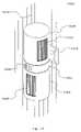
- FIG. 3Ais a perspective view of a first exemplary embodiment a multi-directional air circulating fan of the present invention
- FIG. 3Billustrates an exploded view of the exemplary embodiment of FIG. 3A ;
- FIGS. 3C–3Eillustrate a detailed view of an exemplary coupling that allows articulated movement of the housings of the exemplary embodiment of FIG. 3A ;
- FIGS. 3F–3Hillustrate the effects of an interior dividing wall on the dynamics of the generated air stream according to an exemplary embodiment of the present invention
- FIGS. 3I–3Lillustrate the effects of the air directing grill on the dynamics of the generated air stream according to an exemplary embodiment of the present invention
- FIG. 3Millustrates exemplary proportions and areas of an air directing grill according to an exemplary embodiment of the present invention
- FIGS. 4–5are plan views of multi-directional air flows and coverage areas in accordance with exemplary embodiments of the present invention.
- FIG. 6Aillustrates another exemplary embodiment of a multi-directional air circulating fan utilizing an air generator with a blower air impeller design
- FIG. 6Billustrates another exemplary embodiment of a multi-directional air circulating fan utilizing an air generator with a transverse air impeller design
- FIG. 6Cillustrates another exemplary embodiment of a multi-directional air circulating fan utilizing an air generator with an axial air impeller design
- FIG. 7illustrates another exemplary embodiment of a multi-directional air circulating fan utilizing an air generator with a blower air impeller design located in the base of the apparatus;
- FIG. 8illustrates another exemplary embodiment of a multi-directional air circulating fan
- FIG. 9illustrates another exemplary embodiment of the a multi-directional air circulating fan.
- FIG. 10illustrates another exemplary embodiments of the a multi-directional air circulating fan.
- the followingis a description of a multi-directional air circulation fan that allows the air stream to be divided into multiple streams which can be directed to multiple areas simultaneously.
- the multi-direction air circulating fan described hereinalso allows the user the option of allowing these multiple air streams to be stationary or the ability to oscillate the multiple air streams as desired.
- the described deviceis a multi-directional air circulating fan that further allows the oscillation feature to be adjustable to increase and/or decrease the coverage area of oscillation, thus allowing the generated air stream to return to the user's position more frequently during the oscillation cycle.
- the multi-directional air circulating device describedwill allow the user the choice of fixed, enhanced oscillation and multi-directed air streams.
- the userbenefits from the multiple air streams, one at an upper level to cool his face, for example, and another air stream to provide air circulation to equipment in use, such as a computer monitor or laptop computer.
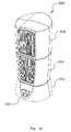
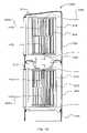
- FIGS. 3A and 3Billustrate a first exemplary embodiment of a multi-directional air circulating fan of the present invention.
- multi-directional fan 300includes base 302 , lower housing or first housing 304 coupled to base 302 , and upper housing or second housing 306 coupled to lower housing 304 .
- Base 302is defined by the portion of multi-directional fan 300 that remains stationary relative to the surface on which multi-directional fan 300 is placed or mounted.
- base 302may also includes controls 329 , such as on/off control and/or oscillation control.
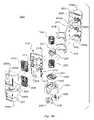
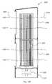
- FIG. 3Bshows an exploded perspective view of multi-directional fan 300 .
- multi-directional fan 300comprises motor 320 , such as a multi-speed motor for example, having one of more shafts 321 that rotate with respect to the frame member of motor 320 .
- Shafts 321are in turn coupled to one or more air impellers 322 , 324 , which in the embodiment show a substantially circular cross section.
- Base 302may include controller 328 (which includes the aforementioned controls 329 ) and, optionally, oscillation control mechanism 326 , such as a motor of well known type. If optional oscillation motor 326 is used, it is desirably coupled to turntable 330 which is disposed in upper section of base 302 . Turntable 330 is in turn coupled to lower housing 304 . Thus, when oscillation motor 326 is activated, lower housing 304 will oscillate accordingly.
- controller 328which includes the aforementioned controls 329
- oscillation control mechanism 326such as a motor of well known type. If optional oscillation motor 326 is used, it is desirably coupled to turntable 330 which is disposed in upper section of base 302 . Turntable 330 is in turn coupled to lower housing 304 . Thus, when oscillation motor 326 is activated, lower housing 304 will oscillate accordingly.
- the range of oscillationis set based on arcuate portions 303 and 331 disposed within base 302 and turntable 330 , respectively.
- the exemplary embodimentshows turntable 330 as separate from lower housing 304 , the invention is not so limited as it is also possible that the function of turntable 330 may be incorporated into lower housing 304 .
- lower housing 304is comprised of front housing 304 b , which includes air outlet 301 , and rear housing 304 a , which includes air inlet 305 .
- Housing 304 b and housing 304 aare coupled to one another.
- an air generation portioncomprised of front section 312 , which includes exhaust port 309 and rear section 316 coupled thereto, with air impeller 322 disposed within space 323 (best seen in FIGS. 3D and 3G ) formed by front section 312 and rear section 316 .
- a grill 308may be coupled to the inside of front housing 304 b proximate air outlet 301 although it is also possible to couple grill 308 at the outside of housing 304 b if desired.
- rear section 316is coupled to rear housing 304 a
- front section 312is coupled to rear section 316 using well known attaching means, such as screws or adhesives for example.
- Upper housing 306is comprised of essentially the same elements described above with respect to lower housing 304 , specifically, grill 310 located proximate air outlet 303 , an air generation portion comprising front section 314 , rear section 318 , and air impeller 324 . These various elements are coupled to and/or disposed within one another similar to lower housing 304 .
- FIGS. 3C , 3 D and 3 Eshow details of the exemplary coupling between upper housing 306 and lower housing 304 .
- upper housing 306is rotatably connected to lower housing 304 through the use of a coupling.
- the couplingcomprises, sleeve 332 , collar 334 , attaching means 338 , such as a screw, and washer 340 .
- attaching means 338such as a screw
- washer 340This embodiment is best shown in the enlarged detail view of FIG. 3E .
- sleeve 332is formed at an upper portion of lower housing 304 and may be an integral part thereof.
- groove 337is formed in the upper surface of lower housing 304 to receive shoulder 339 formed in a lower portion of upper housing 306 .
- the interaction of shoulder 339 as it rides within groove 337limits the rotation of upper housing 306 relative to lower housing 304 .
- the rotation range of upper housing 306 relative to lower housing 304is about 65 degrees. In another exemplary embodiment, the rotation range is up to a full 360 degrees.
- collar 334Adjacent to shoulder 339 is collar 334 which is also formed at the lower portion of upper housing 306 . Collar 334 is disposed adjacent to and guided by sleeve 332 . In assembly, shoulder 339 is placed within groove 337 and collar 334 is placed against sleeve 332 . Attaching means 338 , such as a screw or rivet for example, coupled into mounting hole 336 formed in upper housing 306 , is used to maintain structural integrity between the upper an lower housings. In addition, to provide a smooth low friction surface for rotation of upper housing 306 relative to lower housing 304 , a bearing surface 340 , such as a nylon washer for example, may be placed between the head of attaching means 338 and inner surface of lower housing 304 .
- detentsmay be provided in one or both of upper and lower housings (not shown).
- upper housing 306may include an air impeller 324 , air generator motor 320 , a control section 328 , or any combination thereof.
- Lower section 304may include an air impeller 322 , air generator motor 320 , a control section 328 , or any combination thereof.
- Motor shaft 321 a or 321 bextends from the housing (upper or lower) in which motor 320 is mounted into the adjacent housing to drive a respective air impeller.
- air generator motor 320may be disposed within either lower housing 304 or upper housing 306 or base 302 . It is also possible to dispose a portion of air generator motor 320 within each of lower housing 304 and upper housing 306 , as desired.
- FIGS. 3F , 3 G and 3 Hillustrate airflow through an exemplary multi-directional air circulating fan 300 .
- intake air 348enters housings 304 , 306 thru air inlets 305 , 307 and flows toward rotating air impellers 322 , 324 .
- the rotation of air impellers 322 , 324converts intake air 348 into exhaust air 350 which ultimately exits housing 304 , 306 through air outlet 301 , 303 .
- a portion 351 of exhaust air 350flows back into housing 304 , 306 and mixes with intake air 348 .
- efficiencyis of the air generator is reduced.
- a preferred embodiment of the present inventionutilizes walls 313 , 315
- each of front section 312 , 314include walls 313 , 315 , respectively, which extend between the inner walls of lower housing 304 and upper housing 306 , respectively, dividing the upper and lower housings into two distinct sections, an inlet section 360 and an outlet section 362 .
- Walls 313 , 315prevent the recirculation of exhaust air 350 , thereby increasing the efficiency of multi-directional air circulating fan 300 .
- FIG. 3GThe benefit of walls 313 , 315 is illustrated in FIG. 3G when compared to FIG. 3F .
- walls 313 , 315are illustrated as being oriented at about 180 degrees relative to one another, the invention is not so limited.
- walls 313 ′, 315 ′may be disposed at any desired angle so as to cut off recirculation of exhaust air 350 back into the intake air 348 .
- walls 313 ′, 315 ′are placed adjacent exhaust port 309 , 311 , respectively.
- FIGS. 3F , 3 G and 3 Halso illustrate the exit angle ⁇ 355 at which the maximum velocity vector 354 of air stream 350 exits the multi-directional air circulating fan 300 thru exhaust ports 309 , 311 and air outlets 301 , 303 .
- Angle ⁇ 355is measured relative to centerline 357 of air outlets 301 , 303 .
- Also illustratedis the angular area of dissipation ⁇ 356 of air stream 350 .
- the exit angle ⁇ 355 and the angular area of dissipation ⁇ 356reduces the ability of the user to direct air stream 350 as desired.
- FIG. 3Iis an illustration of an exemplary embodiment of air directing grills 308 , 310 which are located proximate air outlets 301 , 303 and exhaust ports 309 , 311 .
- Air directing grills 308 , 310are comprised of grill elements 352 which serve several purposes, including:
- air directing grill 308 , 310when air directing grills 308 , 310 are located proximate air outlet 301 , 303 and blower outlet 309 , 311 , respectively, air directing grill 308 , 310 will reduce the maximum velocity of air stream 350 when measured on outlet face of air directing grills 308 , 310 by less than about 35% as compared to un-obstructed air outlets 301 , 303 illustrated in FIG. 3G . This will insure minimal impedance to the flow and velocity of air stream 350 .
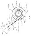
- FIGS. 3J , 3 K and 3 Lillustrate experimental data showing the effects of air directing grills 308 , 310 .
- FIG. 3Jillustrates a multi-directional fan 300 with air directing grills 308 , 310 located at center of 18 inch radius 358 .
- Data collection points 359are equally spaced along radius 358 relative to centerline 357 of air directing grills 308 , 310 .
- FIG. 3Killustrates an air stream velocity data table for a multi-directional air circulating fan 300 with no air directing grills 308 , 310 .
- the maximum velocity vector 354is measured at angle ⁇ 355 at about ⁇ 50 degrees relative to centerline 357 of air outlet 301 , 303 .
- the angular area of dissipation ⁇ 356is also measured between about ⁇ 40 degrees and about ⁇ 65 degrees.
- FIG. 3Lillustrates an air stream velocity data table for a multi-directional air circulating fan 300 utilizing air directing grills 308 , 310 .
- the maximum velocity vector 354is measured at angle ⁇ 355 substantially co-linear to centerline 357 of air directing grills 308 , 310 .
- the angular area of dissipation ⁇ 356is also measured between about +20 degrees and about ⁇ 5 degrees. The angular area of dissipation ⁇ 356 has been reduced by about 20% when compared to data from FIG. 3K .
- grill elements 352have a leading edge curved toward exhaust ports 309 , 311 so as to minimize resistant and/or interference with exhaust air 350 , thus providing a substantially free flow path.
- the air flow velocity of air stream 350has a maximum face velocity, when measured on the surface of the air exit side of air directing grills 308 , 310 of greater than about 475 fpm when the air directing grills 308 , 310 are located proximate air outlets 301 , 303 and blower outlets 309 , 311 .
- the reduction of the maximum velocity measured at about 18 inches from the face of grills 308 , 310 when compared to the maximum face velocity measured on the surface of the air exit side of air directing grills 308 , 310will be less than about 80%.
- an airflow velocity of exhaust air stream 350is about 350 fpm measured at about 40 inches from air directing grill 308 , 310 .
- FIG. 3Millustrates exemplary proportions of air directing grills 308 , 310 .
- Grill elements 352are also dimensioned/configured so as to minimize their impedance to the flow of air stream 350 as it exits multi-directional air circulating fan 300 .
- the overall dimensions of the air directing grills 308 , 310are comprised of height “GH” and width “GW.” Grill elements 352 also have a height “EH” and a width “EW.”
- the air directing grills 308 , 310may have dimensions as described it is possible that the exhaust area 353 of air stream 350 will be much smaller.
- the exhaust area 353 of air stream 350has a height “AH” and a width “AW”.
- the exhaust area 353may correlate substantially to the area of blower outlets 309 , 311 , as best shown in FIG. 3B .
- the theoretical open area “OA” of air directing grill 308 , 310within the exhaust area 353 of the of air stream 350 , is equal to the exhaust area 353 minus the area of all of grill elements 352 , (“AH” multiplied by “EW” multiplied by number “n” of grill elements 352 ) within exhaust area 353 .
- the theoretical open area “OA” of air directing grill 308 , 310 within the exhaust area 353 of the of air stream 350 as it exits air directing grill 308 , 310is greater than about 60% of exhaust area 353 of air stream 350 . This proportion enhances the ability of air stream 350 to exhaust from multi-directional fan 300 with minimal flow impedance.
- air directing grill 308 , 310may be constructed so as to be a separate component attached to multi-directional fan 300 or as an integral part of another component, such as upper and/or lower housings 304 , 306 , for example.
- the exemplary embodiment in FIGS. 3H–3Jillustrates that air directing grill 308 , 310 is comprised of grill elements 352 that are substantially vertical and linear.
- other grill structuresmay be used such as: holes (substantially circular and/or substantially polygonal), diagonal elements and horizontal elements, or a combination of vertical, horizontal, diagonal elements to construct air directing grill 308 , 310 .
- the design and use of air directing grill 308 , 310serves to enhance the ability of air stream 350 to maintain velocity and be directed as desired.
- air stream 350can be divided into multiple air streams 350 a , 350 b emanating from air directing grills 308 , 310 , respectively, thereby allowing the user or multiple users to benefit from the direct cooling effects of air stream 350 at multiple locations.
- This abilityhas advantages over the limited ability of the existing fixed air movement device 100 as shown and described with respect to FIG. 1 , and does not have the disadvantages of the existing oscillating air movement device 200 as shown and described with respect to FIG. 2 .
- multi-directional air circulating fan 300may oscillate in direction 500 .
- air streams 350 a , 350 bprovide cooling over angular area 502 .
- upper housing 306is rotatable with respect to lower housing 304 .
- the angular area of coverage 502 of air streams 350 a , 350 bis based on both the oscillation range and the relative angle between upper and lower sections 304 , 306 . This allows the user to benefit from the direct cooling effect of the air streams 350 a and 350 b more often during each oscillation cycle of multi-directional fan 300 .
- air streams 350 a and 350 bcan be directed so as to increase the angular area 502 that is covered by the air streams 350 a and 350 b as multi-directional fan 300 oscillates. This provides the user the option of covering a larger or smaller area with the air streams generated by multi-directional fan 300 .
- FIG. 6Aillustrates another exemplary embodiment of multi-directional air circulating fan 300 that utilizes an air generator comprising air generator motor 320 coupled to two separate air impellers 322 , 324 .
- air impellers 322 , 324are consistent with a centrifugal blower design.
- Air generator motor 320is located between air impellers 322 and 324 , for example. This allows for the use of a single air generator motor 320 and thereby reduces manufacturing costs.
- FIG. 6Ashows only two air impellers 322 and 324 and a single air generator motor 320 , the invention is not so limited as discussed below.
- FIG. 6Bshows another exemplary embodiment of multi-directional air circulating fan 300 that utilizes an air generator comprising air generator motor 320 disposed within base 302 and coupled to an air impeller 322 ′ which extends between lower housing 304 and upper housing 306 .
- the illustrationshows that air impeller 322 ′ is consistent with a transverse blower design.
- Air generator motor 320may be located at either end of the air impeller 322 ′ or between multiple air impellers (not shown in this figure).
- FIG. 6Bshows only one air impeller 322 ′ and a single air generator motor 320 , the invention is not so limited.
- air impeller 322 ′may be a multi-section air impeller with adjacent sections coupled to one another, for example.
- FIG. 6Cshows another exemplary embodiment is of the multi-directional air circulating fan.
- multi-directional air circulating fan 600utilizes separate air generators in each of the housings.
- three housings 604 , 606 , and 608are shown, with housing 604 coupled to optional base 602 , housing 606 coupled at its lower end to housing 604 and at its upper end to housing 608 .
- housings 604 , 606 , and 608being rotatable with respect to the housing(s) to which it is coupled.
- the coupling between the housingsmay be accomplished similarly to the approach described above with respect to the first exemplary embodiment.
- the coupling between the various housings and basemay be achieved using a collar 622 having a barrier portion 624 to prevent air from flowing between adjacent sections.
- this embodimentis similar to the first exemplary embodiment, including the oscillation feature and exemplary range of rotation between adjacent housings.
- each air generatorcomprises an air generator motor 610 , 614 , 618 coupled to a respective air impeller 612 , 616 , 620 .
- air impellers 612 , 616 , 620have an axial air impeller design and generate respective air flows 350 a , 350 b , 350 c from intake air 348 .
- FIG. 6Cshows only three air impellers 612 , 616 , 620 and three air generator motors 610 , 614 , 618 , this does not limit the invention to only three air impellers and only three air generator motors, as the number of housings and respective air generators may be increased or decreased, as desired.
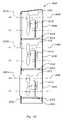
- FIG. 7shows another exemplary embodiment of the multi-directional air circulating fan.
- multi-directional air circulating fan 700utilizes an air generator 708 comprising at least one air generator motor 720 coupled to at least one air impeller 722 .
- air impeller 722is that of a centrifugal blower design.
- Air generator motor 720 and air impeller 722may be located in base 702 of multi-directional air circulating fan 700 , for example. This allows for the use of a single air generator thereby decreases the cost to manufacture the multi-directional fan 700 .
- intake air 348enters base 702 and is converted into exhaust air 350 .
- a portion of exhaust air 350exits lower housing 704 as exhaust air 350 a and the remaining exhaust air 350 passes into upper housing 706 through air passageway 710 , shown in this embodiment as having an downward arcuate shape, and in-turn exhausted from upper housing 706 as exhaust air 350 b .
- channel 710may be formed as part of and/or disposed within lower housing 704 , the invention is not so limited as it is possible to form channel 710 as a separate part, dispose it within upper housing 706 and/or form channel 710 in an upward arcuate or funnel shape, for example.
- the housingsare rotatable with respect to one another.
- lower housing 704may be rotatable and/or oscillate with respect to base 702 .
- an oscillation motor 726may be positioned in either base 702 or lower housing 704 . In all other respects this embodiment is similar to the first exemplary embodiment.
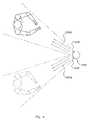
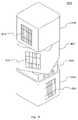
- FIG. 8shows another exemplary embodiment of the multi directional air circulating fan.
- multi-directional air circulating fan 800is comprised of housings 802 , 804 , 806 having a substantially polygonal form.
- control section 828is disposed between the lower housing/base 802 and middle housing 804 .
- One or more air generatorsare disposed in any one of or all of housings 802 , 804 , 806 in accordance with the aforementioned exemplary embodiments. Air exits from housings 802 , 804 , 806 through air directing grills 808 , 810 , 812 respectively.
- FIG. 8shows multi-directional air circulating fan 800 as having three sections, the invention is not so limited as any number of housing sections greater than one may be used as desired.
- FIG. 9shows another exemplary embodiment of the multi directional air circulating fan.
- multi-directional air circulating fan 900having a substantially cylindrical form, is shown and comprised of base 902 , lower housing section 904 , and any number of intermediate housing sections 906 , and upper housing section 910 .
- controller 928is included within top housing section 910 .
- this exemplary embodimentis similar to the aforementioned exemplary embodiments and includes any of the features of those embodiments.
- FIG. 10shows another exemplary embodiment of the multi-directional air circulating fan.
- multi-directional air circulating fan 1000is comprised of lower housing 1004 and upper housing 1006 , each coupled to intermediate section 1002 which may include control section 1028 if desired.
- Intermediate section 1002is coupled to mounting bracket or mount 1012 , which is in-turn used to mount multi-directional air circulating fan 1000 to a mounting surface 1014 , such as a wall or ceiling, for example.
- Mounting bracket 1012may be a separate part or an integral part of one of the components, such as intermediate section 1002 , for example.
- Upper housing 1006 and/or lower housing 1004may be rotatable and/or oscillate with respect to intermediate section 1002 .
- An oscillation motor(not shown) may be disposed in intermediate section 1002 , upper housing 1006 and/or lower housing 1004 . It is also contemplated that upper and lower housings 1004 , 1006 may oscillate in opposite directions if desired.
- Intermediate section 1002may be rotatable and/or oscillate with respect to mounting bracket 1012 . This would allow multi-directional air circulating fan 1000 to rotate and/or oscillate with respect to mounting surface 1014 .
- multi-directional air circulating fan 1000is mounted in a substantially vertical position.
- the inventionis not so limited, however, in that it is also contemplated that multi-directional air circulating fan 1000 could be mounted at any angle including a substantially horizontal position or on a ceiling.
Landscapes
- Engineering & Computer Science (AREA)
- Mechanical Engineering (AREA)
- General Engineering & Computer Science (AREA)
- Structures Of Non-Positive Displacement Pumps (AREA)
Abstract
Description
- The spacing of
grill elements 352 impede the penetration of objects (not shown) into the interior space ofhousings air impeller - The use of air directing grills308 and310 redirects
maximum velocity vector 354 ofair stream 350 to exit the multi-directionalair circulating fan 300 substantially co-linear withcenterline 357 of air directing grills308,310. The use of air directing grills308 and310 also reduce the angular area ofdissipation σ 356 by approximately 20% as compared to not using grills. These features allow the user to more easilydirect air stream 350 as desired.
- The spacing of
OA=
OA>0.6×
Claims (42)
Priority Applications (1)
| Application Number | Priority Date | Filing Date | Title |
|---|---|---|---|
| US10/750,132US7059826B2 (en) | 2003-07-25 | 2003-12-31 | Multi-directional air circulating fan |
Applications Claiming Priority (2)
| Application Number | Priority Date | Filing Date | Title |
|---|---|---|---|
| US49037503P | 2003-07-25 | 2003-07-25 | |
| US10/750,132US7059826B2 (en) | 2003-07-25 | 2003-12-31 | Multi-directional air circulating fan |
Publications (2)
| Publication Number | Publication Date |
|---|---|
| US20050019155A1 US20050019155A1 (en) | 2005-01-27 |
| US7059826B2true US7059826B2 (en) | 2006-06-13 |
Family
ID=34083657
Family Applications (1)
| Application Number | Title | Priority Date | Filing Date |
|---|---|---|---|
| US10/750,132Expired - LifetimeUS7059826B2 (en) | 2003-07-25 | 2003-12-31 | Multi-directional air circulating fan |
Country Status (1)
| Country | Link |
|---|---|
| US (1) | US7059826B2 (en) |
Cited By (89)
| Publication number | Priority date | Publication date | Assignee | Title |
|---|---|---|---|---|
| US20060067818A1 (en)* | 2004-09-27 | 2006-03-30 | Roy Studebaker | Multiple impeller fan for a shrouded floor drying fan |
| US20060120857A1 (en)* | 2004-12-02 | 2006-06-08 | Power Cooler Enterprise Co., Ltd. | Cooling fan assembly capable of adjusting air flow direction |
| USD580028S1 (en)* | 2008-02-06 | 2008-11-04 | Lasko Holdings, Inc. | Body for a portable heater |
| US20090012003A1 (en)* | 1998-03-17 | 2009-01-08 | Genentech, Inc. | Polypeptides homologous to vegf and bmp1 |
| US20090290973A1 (en)* | 2008-05-26 | 2009-11-26 | Chi-Hsiang Wang | Tower fan |
| US20100226751A1 (en)* | 2009-03-04 | 2010-09-09 | Dyson Technology Limited | Fan assembly |
| US20100226753A1 (en)* | 2009-03-04 | 2010-09-09 | Dyson Technology Limited | Fan assembly |
| US20100226801A1 (en)* | 2009-03-04 | 2010-09-09 | Dyson Technology Limited | Fan assembly |
| US20100226752A1 (en)* | 2009-03-04 | 2010-09-09 | Dyson Technology Limited | Fan assembly |
| US20100225012A1 (en)* | 2009-03-04 | 2010-09-09 | Dyson Technology Limited | Humidifying apparatus |
| US20100226769A1 (en)* | 2009-03-04 | 2010-09-09 | Dyson Technology Limited | Fan assembly |
| US20100226758A1 (en)* | 2009-03-04 | 2010-09-09 | Dyson Technology Limited | Fan assembly |
| US20100226787A1 (en)* | 2009-03-04 | 2010-09-09 | Dyson Technology Limited | Fan assembly |
| US20100226797A1 (en)* | 2009-03-04 | 2010-09-09 | Dyson Technology Limited | Fan assembly |
| US20100226754A1 (en)* | 2009-03-04 | 2010-09-09 | Dyson Technology Limited | Fan assembly |
| US20100226764A1 (en)* | 2009-03-04 | 2010-09-09 | Dyson Technology Limited | Fan |
| US20100226749A1 (en)* | 2009-03-04 | 2010-09-09 | Dyson Technology Limited | Fan assembly |
| US20110058935A1 (en)* | 2007-09-04 | 2011-03-10 | Dyson Technology Limited | Fan |
| US20110070070A1 (en)* | 2009-09-18 | 2011-03-24 | Hong Fu Jin Precision Industry (Shenzhen) Co., Ltd | Fan apparatus |
| US20110110805A1 (en)* | 2009-11-06 | 2011-05-12 | Dyson Technology Limited | Fan |
| US20110164959A1 (en)* | 2008-09-23 | 2011-07-07 | Dyson Technology Limited | Fan |
| US20110223014A1 (en)* | 2009-03-04 | 2011-09-15 | Dyson Technology Limited | Fan assembly |
| US20110236229A1 (en)* | 2010-03-23 | 2011-09-29 | Dyson Technology Limited | Accessory for a fan |
| USD649628S1 (en)* | 2011-07-20 | 2011-11-29 | Donald William Bryce | Heating apparatus |
| US20110294413A1 (en)* | 2010-05-28 | 2011-12-01 | Lasko Holdings, Inc. | Portable air moving device with multi-directional grill |
| US20120160823A1 (en)* | 2010-12-28 | 2012-06-28 | Donald William Bryce | Heating apparatus |
| US8348596B2 (en) | 2009-03-04 | 2013-01-08 | Dyson Technology Limited | Fan assembly |
| US8366403B2 (en) | 2010-08-06 | 2013-02-05 | Dyson Technology Limited | Fan assembly |
| US8734094B2 (en) | 2010-08-06 | 2014-05-27 | Dyson Technology Limited | Fan assembly |
| US8864447B1 (en) | 2010-07-01 | 2014-10-21 | Sharon K. Humphrey | Low-profile, ceiling-mounted fan |
| US8873940B2 (en) | 2010-08-06 | 2014-10-28 | Dyson Technology Limited | Fan assembly |
| US8882451B2 (en) | 2010-03-23 | 2014-11-11 | Dyson Technology Limited | Fan |
| US8894354B2 (en) | 2010-09-07 | 2014-11-25 | Dyson Technology Limited | Fan |
| US8967979B2 (en) | 2010-10-18 | 2015-03-03 | Dyson Technology Limited | Fan assembly |
| US8967980B2 (en) | 2010-10-18 | 2015-03-03 | Dyson Technology Limited | Fan assembly |
| US9011116B2 (en) | 2010-05-27 | 2015-04-21 | Dyson Technology Limited | Device for blowing air by means of a nozzle assembly |
| USD728092S1 (en) | 2013-08-01 | 2015-04-28 | Dyson Technology Limited | Fan |
| USD728770S1 (en) | 2013-08-01 | 2015-05-05 | Dyson Technology Limited | Fan |
| USD728769S1 (en) | 2013-08-01 | 2015-05-05 | Dyson Technology Limited | Fan |
| USD729374S1 (en) | 2013-03-07 | 2015-05-12 | Dyson Technology Limited | Fan |
| USD729373S1 (en) | 2013-03-07 | 2015-05-12 | Dyson Technology Limited | Fan |
| USD729375S1 (en) | 2013-03-07 | 2015-05-12 | Dyson Technology Limited | Fan |
| USD729372S1 (en) | 2013-03-07 | 2015-05-12 | Dyson Technology Limited | Fan |
| USD729376S1 (en) | 2013-03-07 | 2015-05-12 | Dyson Technology Limited | Fan |
| USD729925S1 (en) | 2013-03-07 | 2015-05-19 | Dyson Technology Limited | Fan |
| US9127855B2 (en) | 2011-07-27 | 2015-09-08 | Dyson Technology Limited | Fan assembly |
| US9127689B2 (en) | 2009-03-04 | 2015-09-08 | Dyson Technology Limited | Fan assembly |
| US9151299B2 (en) | 2012-02-06 | 2015-10-06 | Dyson Technology Limited | Fan |
| USD746425S1 (en) | 2013-01-18 | 2015-12-29 | Dyson Technology Limited | Humidifier |
| USD746966S1 (en) | 2013-01-18 | 2016-01-05 | Dyson Technology Limited | Humidifier |
| USD747450S1 (en) | 2013-01-18 | 2016-01-12 | Dyson Technology Limited | Humidifier |
| US9249809B2 (en) | 2012-02-06 | 2016-02-02 | Dyson Technology Limited | Fan |
| USD749231S1 (en) | 2013-01-18 | 2016-02-09 | Dyson Technology Limited | Humidifier |
| US9283573B2 (en) | 2012-02-06 | 2016-03-15 | Dyson Technology Limited | Fan assembly |
| US9328739B2 (en) | 2012-01-19 | 2016-05-03 | Dyson Technology Limited | Fan |
| US9366449B2 (en) | 2012-03-06 | 2016-06-14 | Dyson Technology Limited | Humidifying apparatus |
| US9410711B2 (en) | 2013-09-26 | 2016-08-09 | Dyson Technology Limited | Fan assembly |
| US9458853B2 (en) | 2011-07-27 | 2016-10-04 | Dyson Technology Limited | Fan assembly |
| US9568021B2 (en) | 2012-05-16 | 2017-02-14 | Dyson Technology Limited | Fan |
| US9568006B2 (en) | 2012-05-16 | 2017-02-14 | Dyson Technology Limited | Fan |
| WO2017041700A1 (en)* | 2015-09-11 | 2017-03-16 | 珠海格力电器股份有限公司 | Volute fan assembly structure and floor-standing air conditioner |
| WO2017041695A1 (en)* | 2015-09-11 | 2017-03-16 | 珠海格力电器股份有限公司 | Volute fan assembly structure and floor-standing air conditioner |
| US9599356B2 (en) | 2014-07-29 | 2017-03-21 | Dyson Technology Limited | Humidifying apparatus |
| US9732763B2 (en) | 2012-07-11 | 2017-08-15 | Dyson Technology Limited | Fan assembly |
| US9745981B2 (en) | 2011-11-11 | 2017-08-29 | Dyson Technology Limited | Fan assembly |
| US9745996B2 (en) | 2010-12-02 | 2017-08-29 | Dyson Technology Limited | Fan |
| US9752789B2 (en) | 2012-03-06 | 2017-09-05 | Dyson Technology Limited | Humidifying apparatus |
| US9797613B2 (en) | 2012-03-06 | 2017-10-24 | Dyson Technology Limited | Humidifying apparatus |
| US9797612B2 (en) | 2013-01-29 | 2017-10-24 | Dyson Technology Limited | Fan assembly |
| US9797414B2 (en) | 2013-07-09 | 2017-10-24 | Dyson Technology Limited | Fan assembly |
| US9816531B2 (en) | 2008-10-25 | 2017-11-14 | Dyson Technology Limited | Fan utilizing coanda surface |
| US9822778B2 (en) | 2012-04-19 | 2017-11-21 | Dyson Technology Limited | Fan assembly |
| US9903602B2 (en) | 2014-07-29 | 2018-02-27 | Dyson Technology Limited | Humidifying apparatus |
| US9927136B2 (en) | 2012-03-06 | 2018-03-27 | Dyson Technology Limited | Fan assembly |
| US9926804B2 (en) | 2010-11-02 | 2018-03-27 | Dyson Technology Limited | Fan assembly |
| US9982677B2 (en) | 2014-07-29 | 2018-05-29 | Dyson Technology Limited | Fan assembly |
| US10094392B2 (en) | 2011-11-24 | 2018-10-09 | Dyson Technology Limited | Fan assembly |
| US10100836B2 (en) | 2010-10-13 | 2018-10-16 | Dyson Technology Limited | Fan assembly |
| US10145583B2 (en) | 2012-04-04 | 2018-12-04 | Dyson Technology Limited | Heating apparatus |
| US10385867B2 (en)* | 2016-07-19 | 2019-08-20 | Jinhua City Xin'an Electric Co., Ltd. | Multi-directional cooling fan |
| US10408478B2 (en) | 2012-03-06 | 2019-09-10 | Dyson Technology Limited | Humidifying apparatus |
| US10428837B2 (en) | 2012-05-16 | 2019-10-01 | Dyson Technology Limited | Fan |
| US10465928B2 (en) | 2012-03-06 | 2019-11-05 | Dyson Technology Limited | Humidifying apparatus |
| US10612565B2 (en) | 2013-01-29 | 2020-04-07 | Dyson Technology Limited | Fan assembly |
| US20220010799A1 (en)* | 2020-07-10 | 2022-01-13 | Lg Electronics Inc. | Air circulator and air cleaner including air circulator |
| US11378100B2 (en) | 2020-11-30 | 2022-07-05 | E. Mishan & Sons, Inc. | Oscillating portable fan with removable grille |
| US11473593B2 (en)* | 2020-03-04 | 2022-10-18 | Lg Electronics Inc. | Blower comprising a fan installed in an inner space of a lower body having a first and second upper body positioned above and a space formed between the bodies wherein the bodies have a first and second openings formed through respective boundary surfaces which are opened and closed by a door assembly |
| US11585350B2 (en) | 2019-02-11 | 2023-02-21 | Cleva Technologies, Llc | Mobile climate control assembly and method of use |
| US11754090B2 (en) | 2020-03-04 | 2023-09-12 | Lg Electronics Inc. | Blower |
Families Citing this family (9)
| Publication number | Priority date | Publication date | Assignee | Title |
|---|---|---|---|---|
| US20050123392A1 (en)* | 2003-12-08 | 2005-06-09 | The Holmes Group, Inc. | Multi-directional tower fan |
| ITPD20050196A1 (en)* | 2005-06-30 | 2007-01-01 | Emerson Network Power Holding | VENTILATION DEVICE FOR AIR CONDITIONING SYSTEMS |
| CN201176958Y (en)* | 2008-04-07 | 2009-01-07 | 李文生 | Novel tower fan |
| US20130058806A1 (en)* | 2011-09-06 | 2013-03-07 | Yu-Yuan Lin | DC Electric Fan |
| JP5987165B2 (en)* | 2011-11-29 | 2016-09-07 | パナソニックIpマネジメント株式会社 | Blower |
| US9291170B2 (en)* | 2013-06-28 | 2016-03-22 | Intel Corporation | Blower assembly for electronic device |
| US9763361B2 (en) | 2015-09-14 | 2017-09-12 | Google Inc. | Blower tray |
| KR101828885B1 (en)* | 2016-03-02 | 2018-02-13 | 엘지전자 주식회사 | Blower |
| US11236762B2 (en)* | 2019-04-26 | 2022-02-01 | Johnson Controls Technology Company | Variable geometry of a housing for a blower assembly |
Citations (2)
| Publication number | Priority date | Publication date | Assignee | Title |
|---|---|---|---|---|
| US6321034B2 (en) | 1999-12-06 | 2001-11-20 | The Holmes Group, Inc. | Pivotable heater |
| US20040022631A1 (en) | 2002-08-05 | 2004-02-05 | Birdsell Walter G. | Tower fan |
- 2003
- 2003-12-31USUS10/750,132patent/US7059826B2/ennot_activeExpired - Lifetime
Patent Citations (3)
| Publication number | Priority date | Publication date | Assignee | Title |
|---|---|---|---|---|
| US6321034B2 (en) | 1999-12-06 | 2001-11-20 | The Holmes Group, Inc. | Pivotable heater |
| US20040022631A1 (en) | 2002-08-05 | 2004-02-05 | Birdsell Walter G. | Tower fan |
| US6830433B2 (en)* | 2002-08-05 | 2004-12-14 | Kaz, Inc. | Tower fan |
Cited By (137)
| Publication number | Priority date | Publication date | Assignee | Title |
|---|---|---|---|---|
| US20090012003A1 (en)* | 1998-03-17 | 2009-01-08 | Genentech, Inc. | Polypeptides homologous to vegf and bmp1 |
| US20090264370A9 (en)* | 1998-03-17 | 2009-10-22 | Genentech, Inc. | Polypeptides homologous to vegf and bmp1 |
| US7238006B2 (en)* | 2004-09-27 | 2007-07-03 | Studebaker Enterprises, Inc. | Multiple impeller fan for a shrouded floor drying fan |
| US20060067818A1 (en)* | 2004-09-27 | 2006-03-30 | Roy Studebaker | Multiple impeller fan for a shrouded floor drying fan |
| US20060120857A1 (en)* | 2004-12-02 | 2006-06-08 | Power Cooler Enterprise Co., Ltd. | Cooling fan assembly capable of adjusting air flow direction |
| US8764412B2 (en) | 2007-09-04 | 2014-07-01 | Dyson Technology Limited | Fan |
| US20110058935A1 (en)* | 2007-09-04 | 2011-03-10 | Dyson Technology Limited | Fan |
| US9249810B2 (en) | 2007-09-04 | 2016-02-02 | Dyson Technology Limited | Fan |
| US8403650B2 (en) | 2007-09-04 | 2013-03-26 | Dyson Technology Limited | Fan |
| USD580028S1 (en)* | 2008-02-06 | 2008-11-04 | Lasko Holdings, Inc. | Body for a portable heater |
| US20090290973A1 (en)* | 2008-05-26 | 2009-11-26 | Chi-Hsiang Wang | Tower fan |
| US8348629B2 (en) | 2008-09-23 | 2013-01-08 | Dyston Technology Limited | Fan |
| US20110164959A1 (en)* | 2008-09-23 | 2011-07-07 | Dyson Technology Limited | Fan |
| US10145388B2 (en) | 2008-10-25 | 2018-12-04 | Dyson Technology Limited | Fan with a filter |
| US9816531B2 (en) | 2008-10-25 | 2017-11-14 | Dyson Technology Limited | Fan utilizing coanda surface |
| US8403640B2 (en) | 2009-03-04 | 2013-03-26 | Dyson Technology Limited | Fan assembly |
| US8529203B2 (en) | 2009-03-04 | 2013-09-10 | Dyson Technology Limited | Fan assembly |
| US20100226764A1 (en)* | 2009-03-04 | 2010-09-09 | Dyson Technology Limited | Fan |
| US20100226749A1 (en)* | 2009-03-04 | 2010-09-09 | Dyson Technology Limited | Fan assembly |
| US20100226797A1 (en)* | 2009-03-04 | 2010-09-09 | Dyson Technology Limited | Fan assembly |
| US20100226751A1 (en)* | 2009-03-04 | 2010-09-09 | Dyson Technology Limited | Fan assembly |
| US9513028B2 (en)* | 2009-03-04 | 2016-12-06 | Dyson Technology Limited | Fan assembly |
| US9599368B2 (en) | 2009-03-04 | 2017-03-21 | Dyson Technology Limited | Nozzle for bladeless fan assembly with heater |
| US20100226787A1 (en)* | 2009-03-04 | 2010-09-09 | Dyson Technology Limited | Fan assembly |
| US20110223014A1 (en)* | 2009-03-04 | 2011-09-15 | Dyson Technology Limited | Fan assembly |
| US20100226753A1 (en)* | 2009-03-04 | 2010-09-09 | Dyson Technology Limited | Fan assembly |
| US20100226801A1 (en)* | 2009-03-04 | 2010-09-09 | Dyson Technology Limited | Fan assembly |
| US10006657B2 (en) | 2009-03-04 | 2018-06-26 | Dyson Technology Limited | Fan assembly |
| US8197226B2 (en) | 2009-03-04 | 2012-06-12 | Dyson Technology Limited | Fan assembly |
| US10221860B2 (en) | 2009-03-04 | 2019-03-05 | Dyson Technology Limited | Fan assembly |
| US8246317B2 (en) | 2009-03-04 | 2012-08-21 | Dyson Technology Limited | Fan assembly |
| US8308432B2 (en) | 2009-03-04 | 2012-11-13 | Dyson Technology Limited | Fan assembly |
| US20100226752A1 (en)* | 2009-03-04 | 2010-09-09 | Dyson Technology Limited | Fan assembly |
| US8348596B2 (en) | 2009-03-04 | 2013-01-08 | Dyson Technology Limited | Fan assembly |
| US20100226758A1 (en)* | 2009-03-04 | 2010-09-09 | Dyson Technology Limited | Fan assembly |
| US8348597B2 (en) | 2009-03-04 | 2013-01-08 | Dyson Technology Limited | Fan assembly |
| US8356804B2 (en) | 2009-03-04 | 2013-01-22 | Dyson Technology Limited | Humidifying apparatus |
| US8932028B2 (en) | 2009-03-04 | 2015-01-13 | Dyson Technology Limited | Fan assembly |
| US9127689B2 (en) | 2009-03-04 | 2015-09-08 | Dyson Technology Limited | Fan assembly |
| US20100226769A1 (en)* | 2009-03-04 | 2010-09-09 | Dyson Technology Limited | Fan assembly |
| US8408869B2 (en) | 2009-03-04 | 2013-04-02 | Dyson Technology Limited | Fan assembly |
| US8430624B2 (en) | 2009-03-04 | 2013-04-30 | Dyson Technology Limited | Fan assembly |
| US8784071B2 (en) | 2009-03-04 | 2014-07-22 | Dyson Technology Limited | Fan assembly |
| US8469660B2 (en) | 2009-03-04 | 2013-06-25 | Dyson Technology Limited | Fan assembly |
| US8469655B2 (en) | 2009-03-04 | 2013-06-25 | Dyson Technology Limited | Fan assembly |
| US8469658B2 (en) | 2009-03-04 | 2013-06-25 | Dyson Technology Limited | Fan |
| US20100226754A1 (en)* | 2009-03-04 | 2010-09-09 | Dyson Technology Limited | Fan assembly |
| US8783663B2 (en) | 2009-03-04 | 2014-07-22 | Dyson Technology Limited | Humidifying apparatus |
| US8613601B2 (en) | 2009-03-04 | 2013-12-24 | Dyson Technology Limited | Fan assembly |
| US8684687B2 (en) | 2009-03-04 | 2014-04-01 | Dyson Technology Limited | Fan assembly |
| US8708650B2 (en) | 2009-03-04 | 2014-04-29 | Dyson Technology Limited | Fan assembly |
| US8714937B2 (en) | 2009-03-04 | 2014-05-06 | Dyson Technology Limited | Fan assembly |
| US8721286B2 (en) | 2009-03-04 | 2014-05-13 | Dyson Technology Limited | Fan assembly |
| US8784049B2 (en) | 2009-03-04 | 2014-07-22 | Dyson Technology Limited | Fan |
| US20100225012A1 (en)* | 2009-03-04 | 2010-09-09 | Dyson Technology Limited | Humidifying apparatus |
| CN102022356A (en)* | 2009-09-18 | 2011-04-20 | 鸿富锦精密工业(深圳)有限公司 | Fan |
| US20110070070A1 (en)* | 2009-09-18 | 2011-03-24 | Hong Fu Jin Precision Industry (Shenzhen) Co., Ltd | Fan apparatus |
| CN102022356B (en)* | 2009-09-18 | 2013-12-11 | 鸿富锦精密工业(深圳)有限公司 | Fan |
| US8317463B2 (en)* | 2009-09-18 | 2012-11-27 | Hong Fu Jin Precision Industry (Shenzhen) Co., Ltd. | Fan apparatus |
| US8454322B2 (en) | 2009-11-06 | 2013-06-04 | Dyson Technology Limited | Fan having a magnetically attached remote control |
| US9004878B2 (en) | 2009-11-06 | 2015-04-14 | Dyson Technology Limited | Fan having a magnetically attached remote control |
| US20110110805A1 (en)* | 2009-11-06 | 2011-05-12 | Dyson Technology Limited | Fan |
| US8882451B2 (en) | 2010-03-23 | 2014-11-11 | Dyson Technology Limited | Fan |
| US8770946B2 (en) | 2010-03-23 | 2014-07-08 | Dyson Technology Limited | Accessory for a fan |
| US20110236229A1 (en)* | 2010-03-23 | 2011-09-29 | Dyson Technology Limited | Accessory for a fan |
| US9011116B2 (en) | 2010-05-27 | 2015-04-21 | Dyson Technology Limited | Device for blowing air by means of a nozzle assembly |
| US20110294413A1 (en)* | 2010-05-28 | 2011-12-01 | Lasko Holdings, Inc. | Portable air moving device with multi-directional grill |
| US8864447B1 (en) | 2010-07-01 | 2014-10-21 | Sharon K. Humphrey | Low-profile, ceiling-mounted fan |
| US8873940B2 (en) | 2010-08-06 | 2014-10-28 | Dyson Technology Limited | Fan assembly |
| US10344773B2 (en) | 2010-08-06 | 2019-07-09 | Dyson Technology Limited | Fan assembly |
| US8366403B2 (en) | 2010-08-06 | 2013-02-05 | Dyson Technology Limited | Fan assembly |
| US8734094B2 (en) | 2010-08-06 | 2014-05-27 | Dyson Technology Limited | Fan assembly |
| US9745988B2 (en) | 2010-09-07 | 2017-08-29 | Dyson Technology Limited | Fan |
| US8894354B2 (en) | 2010-09-07 | 2014-11-25 | Dyson Technology Limited | Fan |
| US10100836B2 (en) | 2010-10-13 | 2018-10-16 | Dyson Technology Limited | Fan assembly |
| US8967980B2 (en) | 2010-10-18 | 2015-03-03 | Dyson Technology Limited | Fan assembly |
| US8967979B2 (en) | 2010-10-18 | 2015-03-03 | Dyson Technology Limited | Fan assembly |
| US9926804B2 (en) | 2010-11-02 | 2018-03-27 | Dyson Technology Limited | Fan assembly |
| US9745996B2 (en) | 2010-12-02 | 2017-08-29 | Dyson Technology Limited | Fan |
| US20120160823A1 (en)* | 2010-12-28 | 2012-06-28 | Donald William Bryce | Heating apparatus |
| USD649628S1 (en)* | 2011-07-20 | 2011-11-29 | Donald William Bryce | Heating apparatus |
| US9335064B2 (en) | 2011-07-27 | 2016-05-10 | Dyson Technology Limited | Fan assembly |
| US10094581B2 (en) | 2011-07-27 | 2018-10-09 | Dyson Technology Limited | Fan assembly |
| US9458853B2 (en) | 2011-07-27 | 2016-10-04 | Dyson Technology Limited | Fan assembly |
| US9127855B2 (en) | 2011-07-27 | 2015-09-08 | Dyson Technology Limited | Fan assembly |
| US9291361B2 (en) | 2011-07-27 | 2016-03-22 | Dyson Technology Limited | Fan assembly |
| US9745981B2 (en) | 2011-11-11 | 2017-08-29 | Dyson Technology Limited | Fan assembly |
| US10094392B2 (en) | 2011-11-24 | 2018-10-09 | Dyson Technology Limited | Fan assembly |
| US9328739B2 (en) | 2012-01-19 | 2016-05-03 | Dyson Technology Limited | Fan |
| US9249809B2 (en) | 2012-02-06 | 2016-02-02 | Dyson Technology Limited | Fan |
| US9283573B2 (en) | 2012-02-06 | 2016-03-15 | Dyson Technology Limited | Fan assembly |
| US9151299B2 (en) | 2012-02-06 | 2015-10-06 | Dyson Technology Limited | Fan |
| US9366449B2 (en) | 2012-03-06 | 2016-06-14 | Dyson Technology Limited | Humidifying apparatus |
| US10408478B2 (en) | 2012-03-06 | 2019-09-10 | Dyson Technology Limited | Humidifying apparatus |
| US10465928B2 (en) | 2012-03-06 | 2019-11-05 | Dyson Technology Limited | Humidifying apparatus |
| US10563875B2 (en) | 2012-03-06 | 2020-02-18 | Dyson Technology Limited | Humidifying apparatus |
| US9927136B2 (en) | 2012-03-06 | 2018-03-27 | Dyson Technology Limited | Fan assembly |
| US9797613B2 (en) | 2012-03-06 | 2017-10-24 | Dyson Technology Limited | Humidifying apparatus |
| US9752789B2 (en) | 2012-03-06 | 2017-09-05 | Dyson Technology Limited | Humidifying apparatus |
| US10145583B2 (en) | 2012-04-04 | 2018-12-04 | Dyson Technology Limited | Heating apparatus |
| US9822778B2 (en) | 2012-04-19 | 2017-11-21 | Dyson Technology Limited | Fan assembly |
| US9568021B2 (en) | 2012-05-16 | 2017-02-14 | Dyson Technology Limited | Fan |
| US10428837B2 (en) | 2012-05-16 | 2019-10-01 | Dyson Technology Limited | Fan |
| US10309420B2 (en) | 2012-05-16 | 2019-06-04 | Dyson Technology Limited | Fan |
| US9568006B2 (en) | 2012-05-16 | 2017-02-14 | Dyson Technology Limited | Fan |
| US9732763B2 (en) | 2012-07-11 | 2017-08-15 | Dyson Technology Limited | Fan assembly |
| USD747450S1 (en) | 2013-01-18 | 2016-01-12 | Dyson Technology Limited | Humidifier |
| USD746425S1 (en) | 2013-01-18 | 2015-12-29 | Dyson Technology Limited | Humidifier |
| USD746966S1 (en) | 2013-01-18 | 2016-01-05 | Dyson Technology Limited | Humidifier |
| USD749231S1 (en) | 2013-01-18 | 2016-02-09 | Dyson Technology Limited | Humidifier |
| US9797612B2 (en) | 2013-01-29 | 2017-10-24 | Dyson Technology Limited | Fan assembly |
| US10612565B2 (en) | 2013-01-29 | 2020-04-07 | Dyson Technology Limited | Fan assembly |
| USD729373S1 (en) | 2013-03-07 | 2015-05-12 | Dyson Technology Limited | Fan |
| USD729376S1 (en) | 2013-03-07 | 2015-05-12 | Dyson Technology Limited | Fan |
| USD729374S1 (en) | 2013-03-07 | 2015-05-12 | Dyson Technology Limited | Fan |
| USD729925S1 (en) | 2013-03-07 | 2015-05-19 | Dyson Technology Limited | Fan |
| USD729375S1 (en) | 2013-03-07 | 2015-05-12 | Dyson Technology Limited | Fan |
| USD729372S1 (en) | 2013-03-07 | 2015-05-12 | Dyson Technology Limited | Fan |
| US9797414B2 (en) | 2013-07-09 | 2017-10-24 | Dyson Technology Limited | Fan assembly |
| USD728092S1 (en) | 2013-08-01 | 2015-04-28 | Dyson Technology Limited | Fan |
| USD728769S1 (en) | 2013-08-01 | 2015-05-05 | Dyson Technology Limited | Fan |
| USD728770S1 (en) | 2013-08-01 | 2015-05-05 | Dyson Technology Limited | Fan |
| US9410711B2 (en) | 2013-09-26 | 2016-08-09 | Dyson Technology Limited | Fan assembly |
| US9599356B2 (en) | 2014-07-29 | 2017-03-21 | Dyson Technology Limited | Humidifying apparatus |
| US9982677B2 (en) | 2014-07-29 | 2018-05-29 | Dyson Technology Limited | Fan assembly |
| US9903602B2 (en) | 2014-07-29 | 2018-02-27 | Dyson Technology Limited | Humidifying apparatus |
| WO2017041695A1 (en)* | 2015-09-11 | 2017-03-16 | 珠海格力电器股份有限公司 | Volute fan assembly structure and floor-standing air conditioner |
| WO2017041700A1 (en)* | 2015-09-11 | 2017-03-16 | 珠海格力电器股份有限公司 | Volute fan assembly structure and floor-standing air conditioner |
| US10385867B2 (en)* | 2016-07-19 | 2019-08-20 | Jinhua City Xin'an Electric Co., Ltd. | Multi-directional cooling fan |
| US11585350B2 (en) | 2019-02-11 | 2023-02-21 | Cleva Technologies, Llc | Mobile climate control assembly and method of use |
| US11746800B2 (en)* | 2020-03-04 | 2023-09-05 | Lg Electronics Inc. | Blower comprising a fan installed in an inner space of a lower body having a first and second upper body positioned above and a space formed between the bodies wherein the bodies have a first and second openings formed through respective boundary surfaces which are opened and closed by a door assembly |
| US11473593B2 (en)* | 2020-03-04 | 2022-10-18 | Lg Electronics Inc. | Blower comprising a fan installed in an inner space of a lower body having a first and second upper body positioned above and a space formed between the bodies wherein the bodies have a first and second openings formed through respective boundary surfaces which are opened and closed by a door assembly |
| US11754090B2 (en) | 2020-03-04 | 2023-09-12 | Lg Electronics Inc. | Blower |
| US11994147B2 (en) | 2020-03-04 | 2024-05-28 | Lg Electronics Inc. | Blower |
| US20220010799A1 (en)* | 2020-07-10 | 2022-01-13 | Lg Electronics Inc. | Air circulator and air cleaner including air circulator |
| US12152594B2 (en)* | 2020-07-10 | 2024-11-26 | Lg Electronics Inc. | Air circulator and air cleaner including air circulator |
| US11378100B2 (en) | 2020-11-30 | 2022-07-05 | E. Mishan & Sons, Inc. | Oscillating portable fan with removable grille |
Also Published As
| Publication number | Publication date |
|---|---|
| US20050019155A1 (en) | 2005-01-27 |
Similar Documents
| Publication | Publication Date | Title |
|---|---|---|
| US7059826B2 (en) | Multi-directional air circulating fan | |
| KR101214052B1 (en) | A fan assembly | |
| US7699580B2 (en) | Portable air moving device | |
| US20050238478A1 (en) | Multi-directional tower fan | |
| KR101263742B1 (en) | A fan assembly | |
| KR20130081710A (en) | A fan assembly | |
| US9127689B2 (en) | Fan assembly | |
| RU2484383C2 (en) | Fan | |
| US20040120815A1 (en) | Cooling fan | |
| KR20110086186A (en) | Fan assembly | |
| JP5685178B2 (en) | Blower | |
| JP2012132460A (en) | Fan | |
| US20070243816A1 (en) | Multi-pivot tower fan | |
| JP2019148171A (en) | Blower device | |
| JP2022076034A (en) | Multidirectional simultaneous blower having rotatable blowout shell | |
| JPH1183097A (en) | Blower, air cleaning device using the blower, and air conditioner | |
| CN213955436U (en) | Floor type air conditioner indoor unit and air conditioner | |
| JPH08334253A (en) | Space vortex generator | |
| JPH02178542A (en) | Air flow direction changing device for outdoor equipment air conditioner | |
| KR20250120037A (en) | Electric fan with sabonius type | |
| JPH10160233A (en) | Air blowing device | |
| HK1148047B (en) | A fan assembly |
Legal Events
| Date | Code | Title | Description |
|---|---|---|---|
| AS | Assignment | Owner name:LASKO HOLDINGS, INC., DELAWARE Free format text:ASSIGNMENT OF ASSIGNORS INTEREST;ASSIGNOR:LASKO, WILLIAM E.;REEL/FRAME:015351/0525 Effective date:20031231 | |
| STCF | Information on status: patent grant | Free format text:PATENTED CASE | |
| FEPP | Fee payment procedure | Free format text:PAYOR NUMBER ASSIGNED (ORIGINAL EVENT CODE: ASPN); ENTITY STATUS OF PATENT OWNER: LARGE ENTITY | |
| FPAY | Fee payment | Year of fee payment:4 | |
| FPAY | Fee payment | Year of fee payment:8 | |
| AS | Assignment | Owner name:LASKO OPERATION HOLDINGS, LLC, PENNSYLVANIA Free format text:CONVERSION;ASSIGNOR:LASKO HOLDINGS, INC.;REEL/FRAME:040634/0705 Effective date:20161108 | |
| AS | Assignment | Owner name:WELLS FARGO BANK, NATIONAL ASSOCIATION, AS AGENT, Free format text:SECURITY INTEREST;ASSIGNOR:LASKO OPERATION HOLDINGS, LLC;REEL/FRAME:040659/0875 Effective date:20161118 | |
| AS | Assignment | Owner name:HPS INVESTMENT PARTNERS, LLC, NEW YORK Free format text:SECURITY INTEREST;ASSIGNOR:LASKO OPERATION HOLDINGS LLC;REEL/FRAME:040671/0891 Effective date:20161118 | |
| MAFP | Maintenance fee payment | Free format text:PAYMENT OF MAINTENANCE FEE, 12TH YEAR, LARGE ENTITY (ORIGINAL EVENT CODE: M1553) Year of fee payment:12 |