US7058139B2 - Transmitter with transmitter chain phase adjustment on the basis of pre-stored phase information - Google Patents
Transmitter with transmitter chain phase adjustment on the basis of pre-stored phase informationDownload PDFInfo
- Publication number
- US7058139B2 US7058139B2US09/993,985US99398501AUS7058139B2US 7058139 B2US7058139 B2US 7058139B2US 99398501 AUS99398501 AUS 99398501AUS 7058139 B2US7058139 B2US 7058139B2
- Authority
- US
- United States
- Prior art keywords
- phase
- variable gain
- transmitter
- power amplifier
- stored
- Prior art date
- Legal status (The legal status is an assumption and is not a legal conclusion. Google has not performed a legal analysis and makes no representation as to the accuracy of the status listed.)
- Expired - Lifetime, expires
Links
- 238000004891communicationMethods0.000claimsdescription12
- 238000000034methodMethods0.000claimsdescription7
- 238000004364calculation methodMethods0.000description3
- 238000005259measurementMethods0.000description3
- 238000004088simulationMethods0.000description3
- 230000032683agingEffects0.000description2
- 238000013461designMethods0.000description2
- 230000003247decreasing effectEffects0.000description1
- 230000000694effectsEffects0.000description1
- 238000004519manufacturing processMethods0.000description1
- 238000012986modificationMethods0.000description1
- 230000004048modificationEffects0.000description1
- 238000001228spectrumMethods0.000description1
- 238000012360testing methodMethods0.000description1
Images


Classifications
- H—ELECTRICITY
- H04—ELECTRIC COMMUNICATION TECHNIQUE
- H04B—TRANSMISSION
- H04B1/00—Details of transmission systems, not covered by a single one of groups H04B3/00 - H04B13/00; Details of transmission systems not characterised by the medium used for transmission
- H04B1/02—Transmitters
- H04B1/04—Circuits
- H04B1/0475—Circuits with means for limiting noise, interference or distortion
- H—ELECTRICITY
- H03—ELECTRONIC CIRCUITRY
- H03C—MODULATION
- H03C3/00—Angle modulation
- H03C3/38—Angle modulation by converting amplitude modulation to angle modulation
- H03C3/40—Angle modulation by converting amplitude modulation to angle modulation using two signal paths the outputs of which have a predetermined phase difference and at least one output being amplitude-modulated
- H03C3/403—Angle modulation by converting amplitude modulation to angle modulation using two signal paths the outputs of which have a predetermined phase difference and at least one output being amplitude-modulated using two quadrature frequency conversion stages in cascade
- H—ELECTRICITY
- H03—ELECTRONIC CIRCUITRY
- H03C—MODULATION
- H03C3/00—Angle modulation
- H03C3/38—Angle modulation by converting amplitude modulation to angle modulation
- H03C3/40—Angle modulation by converting amplitude modulation to angle modulation using two signal paths the outputs of which have a predetermined phase difference and at least one output being amplitude-modulated
- H03C3/406—Angle modulation by converting amplitude modulation to angle modulation using two signal paths the outputs of which have a predetermined phase difference and at least one output being amplitude-modulated using a feedback loop containing mixers or demodulators
Definitions
- the present inventionrelates to a transmitter, more particularly to phase adjustment of a transmitter chain comprising a quadrature modulator, a variable gain amplifier, an up-converter, and a variable gain power amplifier.
- the present inventionfurther relates to a phase adjuster, to a method of adjusting an overall phase of a transmitter chain, and to a communication device with a phase adjuster in a transmitter chain.
- Such a transmittercan be a transmitter in a full-duplex direct sequence spread-spectrum CDMA system, or any other suitable system with a high dynamic range transmitter output signal.
- Full-duplex CDMA systemsare known in which transmitters have a high dynamic range output signal, typically a dynamic range of more than 70 dB.
- Newer CDMA systemsbut also other systems, are referred to as linear modulation systems in which information is carried on amplitude as well as on phase.
- non-linear amplifierscannot be adopted because the amplitude of a modulated signal varies within a wide range, i.e., the modulated peak signal envelope exhibits large fluctuations. Therefore, amplifiers in a transmitter chain need to be very linear.
- a variable gain power amplifierthat amplifies an up-converted signal of high frequency, e.g. in a GHZ band, meeting linearity requirements over a wide range is not easy.
- such variable gain power amplifiersare optimized in efficiency at maximum signal output but have poor efficiency at low signal output.
- a transmittercomprising:
- the inventionis based on the recognition of the need to make a phase adjustment in the transmitter chain when improving the overall transmitter efficiency by decreasing the gain of the variable gain power amplifier that operates at an radio frequency, and thereby simultaneously increasing the gain of the variable gain amplifier that operates at an intermediate frequency.
- the inventionis further based on the recognition to make such a phase adjustment even when the total gain of the transmitter chain remains constant from one gain state to another gain state.
- the inventionis further based on the recognition that usually no full phase compensation is need because transmitters work according to standards that allow predetermined maximum phase variations over the dynamic range of the signal and with frequency.
- phase variationsshould not be too large because, when transmitting from a portable communication device to base station of a system, such phase variations could lead to a poor bit error rate at the base stations, and, eventually, a call drop.
- the inventorhad considered that overall phase adjustment on the basis of pre-stored information was feasible where others may have thought such an overall phase adjustment might be impractical or even impossible to practically implement.
- the pre-stored informationis stored in a look-up table, and, upon a gain state change of the variable gain power amplifier, from corresponding entries in the look-up table information is used to determine the gain of the variable gain amplifier, and the phase adjustment value.
- the overall phase of the transmitter chainis adjusted by phase rotating quadrature base band signals prior to modulation.
- phase rotating quadrature base band signalsPrior to modulation.
- phase adjustmenteffectively rotates the so-called IQ-constellation.
- Rotation of the IQ-constellation as suchis known in the art, for instance from the U.S. Pat. No. 5,892,774 the contents of which is herewith incorporated by reference. More particularly, in U.S. Pat. No. 5,982,774 phase rotation is shown in FIG. 3 thereof and described in column 6, lines 30–40 where it is disclosed that a phase encoder rotates an (X I , X Q ) pair by an angle ⁇ n [k] to produce a signal (Y I , Y Q ) at its output.
- the transmittermay include a temperature sensor, a battery voltage sensor, and a signal level sensor for providing a DC-signal indicating the amplitude of the output signal at the variable gain power amplifier.
- the look-up tablemay be made multi-dimensional so as to reflect characteristics of the transmitter chain at different temperatures, different battery voltages, and different amplitudes of the RF output signal. In still another dimension, the look-up table may reflect characteristics of the transmitter chain at different frequencies.
- the look-up tablemay also contain phase characteristic data for an RF filter comprised in the transmitter chain, or for other components comprised in the transmitter chain.
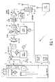
- FIG. 1shows an embodiment of a transmitter according to the invention, in communication with a base station.
- FIG. 2shows another embodiment of a transmitter according to the invention.
- FIG. 3shows rotation of an IQ-constellation at constant signal amplitude.
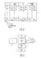
- FIG. 4shows a look-up table according to the invention.
- FIG. 5shows a flow-chart illustrating calculation of a phase adjustment value according to the invention.
- FIG. 1shows an embodiment of transmitter 1 according to the invention, in communication with a base station 2 .
- Transmitter 1comprises a quadrature modulator 3 comprised of multipliers 4 and 5 , an adder 6 , a quadrature phase shifter 7 and an oscillator 8 .
- Quadrature modulator 3modulates a pair of quadrature base band signals Tx_I and Tx_Q.
- Transmitter 1further comprises a variable gain amplifier 9 for amplifying an intermediate frequency output signal from quadrature modulator 3 , and an up-converter 10 comprised of mixers 11 and 12 , an adder 13 , a phase shifter 14 and an oscillator 15 .
- Up-converter 10provides a radio frequency signal to an RF filter 16 .
- Transmitter 1further comprises a variable gain amplifier 17 that is coupled to an antenna 18 via a duplexer 19 .
- Duplexer 19is configured such that a communication device comprising transmitter 1 and further a receiver Rx (not shown in detail here) operates in a full-duplex mode.
- Transmitter 1further comprises a base band unit 20 comprising a processor and storage unit 21 , digital-to-analog converters 23 and a memory 24 comprising a look-up table (LUT) according to the invention.
- Base band unit 20provides control signals C 1 , C 2 and C 3 to at least control the gain of variable gain amplifier 9 and variable gain power amplifier 17 .
- transmitter 1comprises an RF signal level detector 25 that produces a DC output signal indicative of the amplitude of the transmitted RF signal, a temperature sensor 26 , and a battery voltage sensor 27 . From information comprised in look-up table 24 , processor unit 21 calculates the required phase change and controls a quadrature phase rotator 28 such that the IQ-constellation is rotated.
- modulator 3is implemented in hardware.
- FIG. 2shows another embodiment of transmitter 1 according to the invention.
- modulator 3is implemented in software and processor unit is programmed accordingly. Such programming is straightforward once the functionality of the modulator is specified.
- the programmed modulatorhas the same functionality as modulator 3 .
- phase rotation prior to modulationis implemented in software here.
- FIG. 3shows rotation of an IQ-constellation at constant signal amplitude.
- the transmitted RF signal at the output of variable gain power amplifier 17has amplitude Aand has instantaneous in-phase and quadrature components I(t) and Q(t), t being time.
- the overall gain of the transmitter chainis constant, but the gains of variable gain amplifier 9 and variable gain power amplifier 17 are different.
- the first staterepresents high output power at the output of variable gain power amplifier 17
- the second staterepresents low output power at the output of variable gain power amplifier 17 .
- phase variation ⁇ caused by gain changesis compensated through rotation of the IQ-constellation over ⁇ in the opposite direction, so that, ideally, the second state becomes the same as the first state. Because in the second state variable gain power amplifier 17 operates at reduced power, overall transmitter efficiency has improved. Because standards allow predetermined phase variations, compensation does not have to be full compensation. Effects of aging or the like may be analyzed at a design stage of transmitter 1 , e.g. through simulation. From such simulations it can be established that over the lifetime of transmitter 1 phase variations through aging will remain within the specifications as of such standards.
- FIG. 4shows look-up table 24 according to the invention.
- Look-up table 24contains entries at gain states variable gain power amplifier 17 , for variable gain power amplifier 17 , for variable gain amplifier 9 , and for RF band pass filter 16 . Shown are respective gains G 1 PA , G 1 VGA , and G 1 BPF , and respective phases ⁇ 1 PA , ⁇ 1 VGA , and ⁇ 1 BPF at STATE 1 for variable gain power amplifier 17 , for variable gain amplifier 9 , and for RF band pass filter 16 .
- variable gain power amplifier 9With transmitter state change from state 1 to state 2 , the gain of variable gain power amplifier 9 becomes (G 1 VGA ⁇ G 1 PA )/G 2 PA so that the overall transmitter gain remains constant, and ⁇ becomes ⁇ 2 i ⁇ 1 i , ⁇ being a summing operator and i being a running variable of all phases in a particular entry of look-up table 24 . Further indicated in look-up table are ‘TEMP’, ‘BATTERY VOLTAGE’, and ‘FREQUENCY’, indication that lookup table may be multi-dimensional in temperature, battery voltage, and frequency.
- the datamay be put in look-up table 24 at a manufacturing stage, and may be acquired from simulations, from measurements with a vector analyzer, from information from design engineers, or the like. Because no full phase compensation is needed in practice, such data may be acquired for an exemplary transmitter without the need to perform measurements for each and every transmitter, at least no extensive measurements going far beyond usual testing of ICs. Even with process spread, specifications may then be well within requirements set by standards.
- FIG. 5shows a flow-chart illustrating calculation of phase adjustment value ⁇ according to the invention.
- calculationstarts,
- processor 21calculates ⁇ thereby using input variables ‘RF-LEVEL’, ‘TEMPERATURE’, ‘BATTERY VOLTAGE’, and ‘FREQUENCY’.
- processor 21outputs the calculated ⁇ , and in block 33 phase compensation stops.
Landscapes
- Engineering & Computer Science (AREA)
- Computer Networks & Wireless Communication (AREA)
- Signal Processing (AREA)
- Transmitters (AREA)
- Digital Transmission Methods That Use Modulated Carrier Waves (AREA)
Abstract
Description
- a quadrature modulator for providing a quadrature modulated signal from a pair of quadrature base band signals;
- a variable gain amplifier for providing an amplified quadrature modulated signal;
- an up-converter for up-converting said amplified quadrature modulated signal to a higher frequency signal;
- a variable gain power amplifier for providing an amplified higher frequency signal from said higher frequency signal, said amplified higher frequency signal comprising amplitude and phase information; and
- phase adjusting means for adjusting an overall phase of a transmitter chain including said quadrature modulator, said variable gain amplifier, said up-converter, and said variable gain power amplifier, said overall phase being adjusted on the basis of pre-stored phase information reflecting phase changes due to simultaneous gain changes of gains of at least said variable gain amplifier and said variable gain power amplifier.
Claims (20)
Priority Applications (6)
| Application Number | Priority Date | Filing Date | Title |
|---|---|---|---|
| US09/993,985US7058139B2 (en) | 2001-11-16 | 2001-11-16 | Transmitter with transmitter chain phase adjustment on the basis of pre-stored phase information |
| AU2002348958AAU2002348958A1 (en) | 2001-11-16 | 2002-10-30 | Transmitter with transmitter chain phase adjustment on the basis of pre-stored phase information |
| EP02781469AEP1449296A2 (en) | 2001-11-16 | 2002-10-30 | Transmitter with transmitter chain phase adjustment on the basis of pre-stored phase information |
| PCT/IB2002/004553WO2003043179A2 (en) | 2001-11-16 | 2002-10-30 | Transmitter with transmitter chain phase adjustment on the basis of pre-stored phase information |
| JP2003544895AJP2005510105A (en) | 2001-11-16 | 2002-10-30 | Phase adjustment based on prestored phase information for transmitters with transmitter chains |
| CNB028226100ACN100423447C (en) | 2001-11-16 | 2002-10-30 | Transmitter with transmitter chain phase adjustment based on pre-stored phase information |
Applications Claiming Priority (1)
| Application Number | Priority Date | Filing Date | Title |
|---|---|---|---|
| US09/993,985US7058139B2 (en) | 2001-11-16 | 2001-11-16 | Transmitter with transmitter chain phase adjustment on the basis of pre-stored phase information |
Publications (2)
| Publication Number | Publication Date |
|---|---|
| US20030095608A1 US20030095608A1 (en) | 2003-05-22 |
| US7058139B2true US7058139B2 (en) | 2006-06-06 |
Family
ID=25540155
Family Applications (1)
| Application Number | Title | Priority Date | Filing Date |
|---|---|---|---|
| US09/993,985Expired - LifetimeUS7058139B2 (en) | 2001-11-16 | 2001-11-16 | Transmitter with transmitter chain phase adjustment on the basis of pre-stored phase information |
Country Status (6)
| Country | Link |
|---|---|
| US (1) | US7058139B2 (en) |
| EP (1) | EP1449296A2 (en) |
| JP (1) | JP2005510105A (en) |
| CN (1) | CN100423447C (en) |
| AU (1) | AU2002348958A1 (en) |
| WO (1) | WO2003043179A2 (en) |
Cited By (10)
| Publication number | Priority date | Publication date | Assignee | Title |
|---|---|---|---|---|
| US20050233713A1 (en)* | 2004-04-15 | 2005-10-20 | Interdigital Technology Corporation | Method and system for compensating for phase variations caused by transmitter activation |
| US20060094376A1 (en)* | 2004-10-29 | 2006-05-04 | Samsung Electronics Co., Ltd | Apparatus and method for high efficiency power amplification for a mobile communication system |
| US20060183451A1 (en)* | 2003-06-06 | 2006-08-17 | Interdigital Technology Corporation | Method and system for continuously compensating for phase variations introduced into a communication signal by automatic gain control adjustments |
| US20070176681A1 (en)* | 2004-02-12 | 2007-08-02 | Matsushita Electric Industrial Co. Ltd. | Transmission power control device |
| US20070206702A1 (en)* | 2006-02-24 | 2007-09-06 | Bernd Adler | Modulation device for a transmission path, method for signal processing in a transmission path, and transmission path having the modulation device |
| WO2009032408A1 (en)* | 2007-08-31 | 2009-03-12 | Freescale Semiconductor Inc. | Rf circuit with control unit to reduce signal power under appropriate conditions |
| US20140348217A1 (en)* | 2013-05-21 | 2014-11-27 | Mediatek Inc. | Transmitter system with digital phase rotator used for applying digital phase rotation to constellation data and related signal transmission method thereof |
| US9871574B2 (en)* | 2016-04-05 | 2018-01-16 | Getac Technology Corporation | Antenna signal transmission apparatus and antenna signal transmission method |
| US10469109B2 (en)* | 2017-09-19 | 2019-11-05 | Qualcomm Incorporated | Predistortion for transmitter with array |
| US11177847B2 (en)* | 2019-03-22 | 2021-11-16 | Mediatek Singapore Pte. Ltd. | Method for compensating for degradation of signal during transmission of the signal and transmitter utilizing the same |
Families Citing this family (44)
| Publication number | Priority date | Publication date | Assignee | Title |
|---|---|---|---|---|
| US7079588B1 (en)* | 2001-12-21 | 2006-07-18 | Raytheon Company | Method and apparatus for processing signals in an array antenna system |
| US8380143B2 (en) | 2002-05-01 | 2013-02-19 | Dali Systems Co. Ltd | Power amplifier time-delay invariant predistortion methods and apparatus |
| US8472897B1 (en) | 2006-12-22 | 2013-06-25 | Dali Systems Co. Ltd. | Power amplifier predistortion methods and apparatus |
| US8811917B2 (en)* | 2002-05-01 | 2014-08-19 | Dali Systems Co. Ltd. | Digital hybrid mode power amplifier system |
| US6985704B2 (en) | 2002-05-01 | 2006-01-10 | Dali Yang | System and method for digital memorized predistortion for wireless communication |
| GB0212740D0 (en)* | 2002-05-31 | 2002-07-10 | Hitachi Ltd | Transmitter and wireless communication apparatus using the transmitter |
| US7298854B2 (en)* | 2002-12-04 | 2007-11-20 | M/A-Com, Inc. | Apparatus, methods and articles of manufacture for noise reduction in electromagnetic signal processing |
| US7254195B2 (en)* | 2003-08-25 | 2007-08-07 | M/A-Com, Inc. | Apparatus, methods and articles of manufacture for dynamic differential delay correction |
| US7340007B2 (en)* | 2003-09-16 | 2008-03-04 | M/A-Com, Inc. | Apparatus, methods and articles of manufacture for pre-emphasis filtering of a modulated signal |
| US7412008B2 (en)* | 2003-06-30 | 2008-08-12 | Freescale Semiconductor, Inc. | Programmable phase mapping and phase rotation modulator and method |
| DE602005015355D1 (en)* | 2004-11-18 | 2009-08-20 | Research In Motion Ltd | METHOD AND DEVICE FOR PRECISELY TUNING IN OPEN LOOP THE REFERENCE FREQUENCY WITHIN A WIRELESS DEVICE |
| US7426372B2 (en)* | 2005-03-31 | 2008-09-16 | M/A-Com Eurotec B.V. | Piecewise linearizer circuit for radio frequency amplification |
| US7436339B2 (en)* | 2005-07-20 | 2008-10-14 | M/A-Com, Inc. | Method and apparatus to emulate a filter using digital elements |
| US7307570B2 (en)* | 2005-07-20 | 2007-12-11 | M/A-Com, Inc. | Method and apparatus to emulate a filter |
| US7653147B2 (en)* | 2005-08-17 | 2010-01-26 | Intel Corporation | Transmitter control |
| US7599418B2 (en) | 2006-02-16 | 2009-10-06 | Pine Valley Investments, Inc. | Method and apparatus for a frequency hopper |
| CN101479956B (en)* | 2006-04-28 | 2013-07-31 | 大力系统有限公司 | High Efficiency Linearized Power Amplifier for Wireless Communications |
| CN102017553B (en) | 2006-12-26 | 2014-10-15 | 大力系统有限公司 | Method and system for baseband predistortion linearization in a multi-channel broadband communication system |
| US9026067B2 (en)* | 2007-04-23 | 2015-05-05 | Dali Systems Co. Ltd. | Remotely reconfigurable power amplifier system and method |
| US8050783B2 (en)* | 2007-03-12 | 2011-11-01 | Pine Valley Investments, Inc. | System and method for pre-distorting a device input |
| US7869543B2 (en)* | 2007-03-13 | 2011-01-11 | Pine Valley Investments, Inc. | System and method for synchronization, power control, calibration, and modulation in communication transmitters |
| US8009765B2 (en)* | 2007-03-13 | 2011-08-30 | Pine Valley Investments, Inc. | Digital polar transmitter |
| KR101484796B1 (en)* | 2007-04-23 | 2015-01-20 | 달리 시스템즈 씨오. 엘티디. | N-way doherty distributed power amplifier |
| US8274332B2 (en) | 2007-04-23 | 2012-09-25 | Dali Systems Co. Ltd. | N-way Doherty distributed power amplifier with power tracking |
| US8750414B2 (en)* | 2007-07-31 | 2014-06-10 | Broadcom Corporation | Method and system for polar modulation with discontinuous phase |
| US8224266B2 (en)* | 2007-08-30 | 2012-07-17 | Dali Systems Co., Ltd. | Power amplifier predistortion methods and apparatus using envelope and phase detector |
| US8081710B2 (en)* | 2007-11-08 | 2011-12-20 | Pine Valley Investments, Inc. | System and method for corrected modulation with nonlinear power amplification |
| CN102150361B (en) | 2007-12-07 | 2016-11-09 | 大力系统有限公司 | Baseband-derived RF digital predistortion |
| US7983359B2 (en)* | 2008-02-07 | 2011-07-19 | Pine Valley Investments, Inc. | Synchronization techniques for polar transmitters |
| US8233852B2 (en)* | 2008-04-04 | 2012-07-31 | Pine Valley Investments, Inc. | Calibration techniques for non-linear devices |
| KR101133747B1 (en)* | 2009-11-23 | 2012-04-09 | 한국전자통신연구원 | Apparatus and method for transmitting data in a terminal of satellite communication system |
| EP3068047A3 (en) | 2009-12-21 | 2017-03-01 | Dali Systems Co. Ltd. | Modulation agnostic digital hybrid mode power amplifier system and method |
| CN103597807B (en) | 2010-09-14 | 2015-09-30 | 大理系统有限公司 | Remotely reconfigurable distributed antenna system and method |
| CN102683768A (en)* | 2012-05-08 | 2012-09-19 | 武汉滨湖电子有限责任公司 | Self-adaptive phase compensation phase shifter and method along with temperature and frequency |
| US10240456B2 (en)* | 2013-03-15 | 2019-03-26 | Merlin Technology, Inc. | Inground device with advanced transmit power control and associated methods |
| US9425619B2 (en) | 2013-03-15 | 2016-08-23 | Merlin Technology, Inc. | Advanced inground device power control and associated methods |
| WO2016013143A1 (en)* | 2014-07-22 | 2016-01-28 | 日本電気株式会社 | Wireless transmission device and wireless transmission method |
| US10637460B2 (en) | 2016-06-14 | 2020-04-28 | Macom Technology Solutions Holdings, Inc. | Circuits and operating methods thereof for monitoring and protecting a device |
| US20180109228A1 (en) | 2016-10-14 | 2018-04-19 | MACOM Technology Solution Holdings, Inc. | Phase shifters for gallium nitride amplifiers and related methods |
| US20190028066A1 (en) | 2017-07-24 | 2019-01-24 | Macom Technology Solutions Holdings, Inc. | Fet operational temperature determination by field plate resistance thermometry |
| US20190028065A1 (en) | 2017-07-24 | 2019-01-24 | Macom Technology Solutions Holdings, Inc. | Fet operational temperature determination by gate structure resistance thermometry |
| CN107968680B (en)* | 2017-12-01 | 2019-11-22 | 清华大学 | Compensation method and device for optical nonlinear effect |
| US11994023B2 (en) | 2021-06-22 | 2024-05-28 | Merlin Technology, Inc. | Sonde with advanced battery power conservation and associated methods |
| JP2023145873A (en)* | 2022-03-29 | 2023-10-12 | 株式会社Nttドコモ | Radio transmission device |
Citations (27)
| Publication number | Priority date | Publication date | Assignee | Title |
|---|---|---|---|---|
| US4194200A (en)* | 1977-05-31 | 1980-03-18 | The United States Of America As Represented By The Secretary Of The Air Force | Combined receiver protector, AGC attenuator and sensitivity time control device |
| US4291277A (en)* | 1979-05-16 | 1981-09-22 | Harris Corporation | Adaptive predistortion technique for linearizing a power amplifier for digital data systems |
| US5123031A (en)* | 1989-02-08 | 1992-06-16 | Nokia-Mobira Oy | Control voltage generator in a transmitter arrangement for digitally modulated signals |
| US5202906A (en)* | 1986-12-23 | 1993-04-13 | Nippon Telegraph And Telephone Company | Frequency divider which has a variable length first cycle by changing a division ratio after the first cycle and a frequency synthesizer using same |
| US5220557A (en)* | 1991-09-23 | 1993-06-15 | Hughes Aircraft Company | Multiple use digital transmitter/transceiver with time multiplexing |
| US5396217A (en)* | 1993-02-01 | 1995-03-07 | General Motors Corporation | Phase shift analysis for vehicle intrusion detection |
| US5579346A (en)* | 1994-01-19 | 1996-11-26 | Kabushiki Kaisha Toshiba | Automatic frequency control method and circuit for use in a delay detection type demodulator |
| US5892774A (en) | 1996-12-12 | 1999-04-06 | Qualcomm Incorporated | Phase shift encoded subchannel |
| EP0967717A2 (en) | 1998-05-27 | 1999-12-29 | Nokia Mobile Phones Ltd. | Predistortion control for power reduction |
| US6046649A (en) | 1998-11-27 | 2000-04-04 | Lockheed Martin Corporation | Communication system employing paired power amplifiers and drift compensation feedback control loops |
| GB2348062A (en) | 1999-03-19 | 2000-09-20 | Simoco Int Ltd | An arrangement for training a transmitter to linearize its output for two or more values of an operating parameter such as frequency or power |
| WO2000059174A1 (en) | 1999-03-26 | 2000-10-05 | Nokia Networks Oy | Correction of phase and amplitude imbalance of i/q modulator |
| WO2000072438A1 (en) | 1999-05-25 | 2000-11-30 | Nokia Networks Oy | Linearisation and modulation device |
| US6246286B1 (en)* | 1999-10-26 | 2001-06-12 | Telefonaktiebolaget Lm Ericsson | Adaptive linearization of power amplifiers |
| US6275103B1 (en)* | 1998-09-02 | 2001-08-14 | Fujitsu Limited | Predistorter of amplifier and amplifying unit |
| US6288610B1 (en)* | 1998-03-19 | 2001-09-11 | Fujitsu Limited | Method and apparatus for correcting signals, apparatus for compensating for distortion, apparatus for preparing distortion compensating data, and transmitter |
| US6295442B1 (en)* | 1998-12-07 | 2001-09-25 | Ericsson Inc. | Amplitude modulation to phase modulation cancellation method in an RF amplifier |
| US6304140B1 (en)* | 2000-06-12 | 2001-10-16 | Motorola, Inc. | Digital predistortion for amplifiers |
| US20020061050A1 (en)* | 1995-06-30 | 2002-05-23 | Ozluturk Fatih M. | Method for initial power control for spread-spectrum communications |
| US6404823B1 (en)* | 1998-07-01 | 2002-06-11 | Conexant Systems, Inc. | Envelope feedforward technique with power control for efficient linear RF power amplification |
| US6489844B2 (en)* | 1999-12-28 | 2002-12-03 | Japan Radio Co., Ltd. | Feed-forward amplifier and controller of the same |
| US6539052B1 (en)* | 1997-11-03 | 2003-03-25 | Harris Corporation | System for accelerating the reconfiguration of a transceiver and method therefor |
| US6614854B1 (en)* | 1999-05-28 | 2003-09-02 | Carriercomm, Inc. | System and method for adaptive predistortion |
| US20040037364A1 (en)* | 2000-03-31 | 2004-02-26 | Olivier Gagey | Device for producing a phase and amplitude modulated radio frequency signal |
| US6721370B1 (en)* | 1998-10-21 | 2004-04-13 | Nec Corporation | Phase correction circuit for radio communication apparatus |
| US6831954B1 (en)* | 2000-02-01 | 2004-12-14 | Nokia Corporation | Apparatus, and associated method, for compensating for distortion introduced upon a send signal by an amplifier |
| US6853690B1 (en)* | 1999-04-16 | 2005-02-08 | Parkervision, Inc. | Method, system and apparatus for balanced frequency up-conversion of a baseband signal and 4-phase receiver and transceiver embodiments |
Family Cites Families (7)
| Publication number | Priority date | Publication date | Assignee | Title |
|---|---|---|---|---|
| JPH05121958A (en)* | 1991-10-29 | 1993-05-18 | Saitama Nippon Denki Kk | Distortion compensation control system for linear amplifier |
| GB9320078D0 (en)* | 1993-09-29 | 1993-11-17 | Linear Modulation Tech | Cartesian amplifier power control and related applications |
| US5732333A (en)* | 1996-02-14 | 1998-03-24 | Glenayre Electronics, Inc. | Linear transmitter using predistortion |
| US5867065A (en)* | 1997-05-07 | 1999-02-02 | Glenayre Electronics, Inc. | Frequency selective predistortion in a linear transmitter |
| US5933767A (en)* | 1997-09-15 | 1999-08-03 | Motorola, Inc. | Apparatus and method for tuning the gain of a transmitter utilizing cartesian feedback |
| JP3570898B2 (en)* | 1998-08-24 | 2004-09-29 | 日本電気株式会社 | Pre-distortion circuit |
| JP3618055B2 (en)* | 1999-02-05 | 2005-02-09 | 富士通株式会社 | Portable mobile terminal and transmitter |
- 2001
- 2001-11-16USUS09/993,985patent/US7058139B2/ennot_activeExpired - Lifetime
- 2002
- 2002-10-30WOPCT/IB2002/004553patent/WO2003043179A2/ennot_activeApplication Discontinuation
- 2002-10-30AUAU2002348958Apatent/AU2002348958A1/ennot_activeAbandoned
- 2002-10-30EPEP02781469Apatent/EP1449296A2/ennot_activeWithdrawn
- 2002-10-30JPJP2003544895Apatent/JP2005510105A/ennot_activeWithdrawn
- 2002-10-30CNCNB028226100Apatent/CN100423447C/ennot_activeExpired - Fee Related
Patent Citations (27)
| Publication number | Priority date | Publication date | Assignee | Title |
|---|---|---|---|---|
| US4194200A (en)* | 1977-05-31 | 1980-03-18 | The United States Of America As Represented By The Secretary Of The Air Force | Combined receiver protector, AGC attenuator and sensitivity time control device |
| US4291277A (en)* | 1979-05-16 | 1981-09-22 | Harris Corporation | Adaptive predistortion technique for linearizing a power amplifier for digital data systems |
| US5202906A (en)* | 1986-12-23 | 1993-04-13 | Nippon Telegraph And Telephone Company | Frequency divider which has a variable length first cycle by changing a division ratio after the first cycle and a frequency synthesizer using same |
| US5123031A (en)* | 1989-02-08 | 1992-06-16 | Nokia-Mobira Oy | Control voltage generator in a transmitter arrangement for digitally modulated signals |
| US5220557A (en)* | 1991-09-23 | 1993-06-15 | Hughes Aircraft Company | Multiple use digital transmitter/transceiver with time multiplexing |
| US5396217A (en)* | 1993-02-01 | 1995-03-07 | General Motors Corporation | Phase shift analysis for vehicle intrusion detection |
| US5579346A (en)* | 1994-01-19 | 1996-11-26 | Kabushiki Kaisha Toshiba | Automatic frequency control method and circuit for use in a delay detection type demodulator |
| US20020061050A1 (en)* | 1995-06-30 | 2002-05-23 | Ozluturk Fatih M. | Method for initial power control for spread-spectrum communications |
| US5892774A (en) | 1996-12-12 | 1999-04-06 | Qualcomm Incorporated | Phase shift encoded subchannel |
| US6539052B1 (en)* | 1997-11-03 | 2003-03-25 | Harris Corporation | System for accelerating the reconfiguration of a transceiver and method therefor |
| US6288610B1 (en)* | 1998-03-19 | 2001-09-11 | Fujitsu Limited | Method and apparatus for correcting signals, apparatus for compensating for distortion, apparatus for preparing distortion compensating data, and transmitter |
| EP0967717A2 (en) | 1998-05-27 | 1999-12-29 | Nokia Mobile Phones Ltd. | Predistortion control for power reduction |
| US6404823B1 (en)* | 1998-07-01 | 2002-06-11 | Conexant Systems, Inc. | Envelope feedforward technique with power control for efficient linear RF power amplification |
| US6275103B1 (en)* | 1998-09-02 | 2001-08-14 | Fujitsu Limited | Predistorter of amplifier and amplifying unit |
| US6721370B1 (en)* | 1998-10-21 | 2004-04-13 | Nec Corporation | Phase correction circuit for radio communication apparatus |
| US6046649A (en) | 1998-11-27 | 2000-04-04 | Lockheed Martin Corporation | Communication system employing paired power amplifiers and drift compensation feedback control loops |
| US6295442B1 (en)* | 1998-12-07 | 2001-09-25 | Ericsson Inc. | Amplitude modulation to phase modulation cancellation method in an RF amplifier |
| GB2348062A (en) | 1999-03-19 | 2000-09-20 | Simoco Int Ltd | An arrangement for training a transmitter to linearize its output for two or more values of an operating parameter such as frequency or power |
| WO2000059174A1 (en) | 1999-03-26 | 2000-10-05 | Nokia Networks Oy | Correction of phase and amplitude imbalance of i/q modulator |
| US6853690B1 (en)* | 1999-04-16 | 2005-02-08 | Parkervision, Inc. | Method, system and apparatus for balanced frequency up-conversion of a baseband signal and 4-phase receiver and transceiver embodiments |
| WO2000072438A1 (en) | 1999-05-25 | 2000-11-30 | Nokia Networks Oy | Linearisation and modulation device |
| US6614854B1 (en)* | 1999-05-28 | 2003-09-02 | Carriercomm, Inc. | System and method for adaptive predistortion |
| US6246286B1 (en)* | 1999-10-26 | 2001-06-12 | Telefonaktiebolaget Lm Ericsson | Adaptive linearization of power amplifiers |
| US6489844B2 (en)* | 1999-12-28 | 2002-12-03 | Japan Radio Co., Ltd. | Feed-forward amplifier and controller of the same |
| US6831954B1 (en)* | 2000-02-01 | 2004-12-14 | Nokia Corporation | Apparatus, and associated method, for compensating for distortion introduced upon a send signal by an amplifier |
| US20040037364A1 (en)* | 2000-03-31 | 2004-02-26 | Olivier Gagey | Device for producing a phase and amplitude modulated radio frequency signal |
| US6304140B1 (en)* | 2000-06-12 | 2001-10-16 | Motorola, Inc. | Digital predistortion for amplifiers |
Cited By (16)
| Publication number | Priority date | Publication date | Assignee | Title |
|---|---|---|---|---|
| US20060183451A1 (en)* | 2003-06-06 | 2006-08-17 | Interdigital Technology Corporation | Method and system for continuously compensating for phase variations introduced into a communication signal by automatic gain control adjustments |
| US20070176681A1 (en)* | 2004-02-12 | 2007-08-02 | Matsushita Electric Industrial Co. Ltd. | Transmission power control device |
| US7496375B2 (en)* | 2004-02-12 | 2009-02-24 | Panasonic Corporation | Transmission power control device |
| US20050233713A1 (en)* | 2004-04-15 | 2005-10-20 | Interdigital Technology Corporation | Method and system for compensating for phase variations caused by transmitter activation |
| US7400864B2 (en)* | 2004-04-15 | 2008-07-15 | Interdigital Technology Corporation | Method and apparatus for compensating for phase variations caused by activation of an amplifier |
| US7551904B2 (en)* | 2004-10-29 | 2009-06-23 | Samsung Electronics Co., Ltd | Apparatus and method for high efficiency power amplification for a mobile communication system |
| US20060094376A1 (en)* | 2004-10-29 | 2006-05-04 | Samsung Electronics Co., Ltd | Apparatus and method for high efficiency power amplification for a mobile communication system |
| US20070206702A1 (en)* | 2006-02-24 | 2007-09-06 | Bernd Adler | Modulation device for a transmission path, method for signal processing in a transmission path, and transmission path having the modulation device |
| US8374279B2 (en)* | 2006-02-24 | 2013-02-12 | Intel Mobile Communications GmbH | Modulation device for a transmission path, method for signal processing in a transmission path, and transmission path having the modulation device |
| US7941110B2 (en) | 2007-07-23 | 2011-05-10 | Freescale Semiconductor, Inc. | RF circuit with control unit to reduce signal power under appropriate conditions |
| WO2009032408A1 (en)* | 2007-08-31 | 2009-03-12 | Freescale Semiconductor Inc. | Rf circuit with control unit to reduce signal power under appropriate conditions |
| US20140348217A1 (en)* | 2013-05-21 | 2014-11-27 | Mediatek Inc. | Transmitter system with digital phase rotator used for applying digital phase rotation to constellation data and related signal transmission method thereof |
| US9094004B2 (en)* | 2013-05-21 | 2015-07-28 | Mediatek Inc. | Transmitter system with digital phase rotator used for applying digital phase rotation to constellation data and related signal transmission method thereof |
| US9871574B2 (en)* | 2016-04-05 | 2018-01-16 | Getac Technology Corporation | Antenna signal transmission apparatus and antenna signal transmission method |
| US10469109B2 (en)* | 2017-09-19 | 2019-11-05 | Qualcomm Incorporated | Predistortion for transmitter with array |
| US11177847B2 (en)* | 2019-03-22 | 2021-11-16 | Mediatek Singapore Pte. Ltd. | Method for compensating for degradation of signal during transmission of the signal and transmitter utilizing the same |
Also Published As
| Publication number | Publication date |
|---|---|
| CN1586036A (en) | 2005-02-23 |
| WO2003043179A2 (en) | 2003-05-22 |
| AU2002348958A1 (en) | 2003-05-26 |
| JP2005510105A (en) | 2005-04-14 |
| US20030095608A1 (en) | 2003-05-22 |
| WO2003043179A3 (en) | 2003-11-27 |
| EP1449296A2 (en) | 2004-08-25 |
| CN100423447C (en) | 2008-10-01 |
Similar Documents
| Publication | Publication Date | Title |
|---|---|---|
| US7058139B2 (en) | Transmitter with transmitter chain phase adjustment on the basis of pre-stored phase information | |
| US8081711B2 (en) | Predistortion methods and apparatus for polar modulation transmitters | |
| US6633199B2 (en) | Amplifier circuit, radio transmitter, method and use | |
| US7915954B2 (en) | Amplifier predistortion and autocalibration method and apparatus | |
| US6463264B1 (en) | Wireless communication apparatus and transmission power control method in wireless communication apparatus | |
| US7277678B2 (en) | Fast closed-loop power control for non-constant envelope modulation | |
| US5423082A (en) | Method for a transmitter to compensate for varying loading without an isolator | |
| KR100545964B1 (en) | Method and apparatus utilizing a compensated multiple output signal source | |
| EP0881807B1 (en) | Tansmitter with linearised amplifier | |
| US7830220B2 (en) | Modulator arrangement and method for signal modulation | |
| US20070129025A1 (en) | Open loop polar transmitter having on-chip calibration | |
| US20030125065A1 (en) | Method and apparatus for generating an output signal | |
| US7596125B2 (en) | Adjusting the amplitude and phase characteristics of transmitter generated wireless communication signals in response to base station transmit power control signals and known transmitter amplifier characteristics | |
| US9793871B1 (en) | Apparatus and method for controlling wireless transmission | |
| EP1217753A1 (en) | Linear RF power amplifier and transmitter | |
| US6519293B1 (en) | Radio transmitter and radio communication method | |
| EP1450482B1 (en) | Circuit and method for compensating for nonlinear distortion of power amplifier | |
| US20070184789A1 (en) | Cartesian loop transmitter and method of adjusting an output level of such transmitter | |
| EP1639700B1 (en) | Cartesian loop transmitter and method of adjusting an output level of such transmitter | |
| US20060234661A1 (en) | Semiconductor integrated circuit for communication and portable communication terminal | |
| US9667282B1 (en) | Method and apparatus for adaptive gain control and antenna load compensation | |
| JP2004064733A (en) | Distortion compensator | |
| EP1665522B1 (en) | Digital predistortion for power amplifier | |
| US7593699B2 (en) | Distortion/efficiency adaptation in a variable-data-rate radio transmitter | |
| US7940859B2 (en) | Transmission circuit and communication device |
Legal Events
| Date | Code | Title | Description |
|---|---|---|---|
| AS | Assignment | Owner name:KONINKLIJKE PHILIPS ELECTRONICS N.V., NETHERLANDS Free format text:ASSIGNMENT OF ASSIGNORS INTEREST;ASSIGNOR:DUPERRAY, DAVID BENOIT DIDIER;REEL/FRAME:012337/0032 Effective date:20011114 | |
| STCF | Information on status: patent grant | Free format text:PATENTED CASE | |
| AS | Assignment | Owner name:NXP B.V., NETHERLANDS Free format text:ASSIGNMENT OF ASSIGNORS INTEREST;ASSIGNOR:KONINKLIJKE PHILIPS ELECTRONICS N.V.;REEL/FRAME:018635/0787 Effective date:20061117 | |
| FEPP | Fee payment procedure | Free format text:PAYOR NUMBER ASSIGNED (ORIGINAL EVENT CODE: ASPN); ENTITY STATUS OF PATENT OWNER: LARGE ENTITY | |
| FPAY | Fee payment | Year of fee payment:4 | |
| FPAY | Fee payment | Year of fee payment:8 | |
| AS | Assignment | Owner name:ST WIRELESS SA, SWITZERLAND Free format text:ASSIGNMENT OF ASSIGNORS INTEREST;ASSIGNOR:NXP B.V.;REEL/FRAME:037624/0831 Effective date:20080728 | |
| AS | Assignment | Owner name:ST-ERICSSON SA, SWITZERLAND Free format text:CHANGE OF NAME;ASSIGNOR:ST WIRELESS SA;REEL/FRAME:037683/0128 Effective date:20080714 Owner name:ST-ERICSSON SA, EN LIQUIDATION, SWITZERLAND Free format text:STATUS CHANGE-ENTITY IN LIQUIDATION;ASSIGNOR:ST-ERICSSON SA;REEL/FRAME:037739/0493 Effective date:20150223 | |
| MAFP | Maintenance fee payment | Free format text:PAYMENT OF MAINTENANCE FEE, 12TH YEAR, LARGE ENTITY (ORIGINAL EVENT CODE: M1553) Year of fee payment:12 |