US7057647B1 - Dual-mode camera system for day/night or variable zoom operation - Google Patents
Dual-mode camera system for day/night or variable zoom operationDownload PDFInfo
- Publication number
- US7057647B1 US7057647B1US09/593,901US59390100AUS7057647B1US 7057647 B1US7057647 B1US 7057647B1US 59390100 AUS59390100 AUS 59390100AUS 7057647 B1US7057647 B1US 7057647B1
- Authority
- US
- United States
- Prior art keywords
- image
- camera
- iris
- sensor
- image sensor
- Prior art date
- Legal status (The legal status is an assumption and is not a legal conclusion. Google has not performed a legal analysis and makes no representation as to the accuracy of the status listed.)
- Expired - Fee Related, expires
Links
Images


Classifications
- G—PHYSICS
- G02—OPTICS
- G02B—OPTICAL ELEMENTS, SYSTEMS OR APPARATUS
- G02B13/00—Optical objectives specially designed for the purposes specified below
- G02B13/16—Optical objectives specially designed for the purposes specified below for use in conjunction with image converters or intensifiers, or for use with projectors, e.g. objectives for projection TV
- G—PHYSICS
- G03—PHOTOGRAPHY; CINEMATOGRAPHY; ANALOGOUS TECHNIQUES USING WAVES OTHER THAN OPTICAL WAVES; ELECTROGRAPHY; HOLOGRAPHY
- G03B—APPARATUS OR ARRANGEMENTS FOR TAKING PHOTOGRAPHS OR FOR PROJECTING OR VIEWING THEM; APPARATUS OR ARRANGEMENTS EMPLOYING ANALOGOUS TECHNIQUES USING WAVES OTHER THAN OPTICAL WAVES; ACCESSORIES THEREFOR
- G03B17/00—Details of cameras or camera bodies; Accessories therefor
- G03B17/02—Bodies
- G03B17/16—Bodies for containing both motion-picture camera and still-picture camera
- G—PHYSICS
- G03—PHOTOGRAPHY; CINEMATOGRAPHY; ANALOGOUS TECHNIQUES USING WAVES OTHER THAN OPTICAL WAVES; ELECTROGRAPHY; HOLOGRAPHY
- G03B—APPARATUS OR ARRANGEMENTS FOR TAKING PHOTOGRAPHS OR FOR PROJECTING OR VIEWING THEM; APPARATUS OR ARRANGEMENTS EMPLOYING ANALOGOUS TECHNIQUES USING WAVES OTHER THAN OPTICAL WAVES; ACCESSORIES THEREFOR
- G03B17/00—Details of cameras or camera bodies; Accessories therefor
- G03B17/48—Details of cameras or camera bodies; Accessories therefor adapted for combination with other photographic or optical apparatus
- G—PHYSICS
- G03—PHOTOGRAPHY; CINEMATOGRAPHY; ANALOGOUS TECHNIQUES USING WAVES OTHER THAN OPTICAL WAVES; ELECTROGRAPHY; HOLOGRAPHY
- G03B—APPARATUS OR ARRANGEMENTS FOR TAKING PHOTOGRAPHS OR FOR PROJECTING OR VIEWING THEM; APPARATUS OR ARRANGEMENTS EMPLOYING ANALOGOUS TECHNIQUES USING WAVES OTHER THAN OPTICAL WAVES; ACCESSORIES THEREFOR
- G03B19/00—Cameras
- G03B19/18—Motion-picture cameras
- G03B19/22—Double cameras
- H—ELECTRICITY
- H04—ELECTRIC COMMUNICATION TECHNIQUE
- H04N—PICTORIAL COMMUNICATION, e.g. TELEVISION
- H04N23/00—Cameras or camera modules comprising electronic image sensors; Control thereof
- H04N23/10—Cameras or camera modules comprising electronic image sensors; Control thereof for generating image signals from different wavelengths
- H04N23/11—Cameras or camera modules comprising electronic image sensors; Control thereof for generating image signals from different wavelengths for generating image signals from visible and infrared light wavelengths
- H—ELECTRICITY
- H04—ELECTRIC COMMUNICATION TECHNIQUE
- H04N—PICTORIAL COMMUNICATION, e.g. TELEVISION
- H04N23/00—Cameras or camera modules comprising electronic image sensors; Control thereof
- H04N23/45—Cameras or camera modules comprising electronic image sensors; Control thereof for generating image signals from two or more image sensors being of different type or operating in different modes, e.g. with a CMOS sensor for moving images in combination with a charge-coupled device [CCD] for still images
- H—ELECTRICITY
- H04—ELECTRIC COMMUNICATION TECHNIQUE
- H04N—PICTORIAL COMMUNICATION, e.g. TELEVISION
- H04N23/00—Cameras or camera modules comprising electronic image sensors; Control thereof
- H04N23/60—Control of cameras or camera modules
- H04N23/667—Camera operation mode switching, e.g. between still and video, sport and normal or high- and low-resolution modes
- H—ELECTRICITY
- H04—ELECTRIC COMMUNICATION TECHNIQUE
- H04N—PICTORIAL COMMUNICATION, e.g. TELEVISION
- H04N23/00—Cameras or camera modules comprising electronic image sensors; Control thereof
- H04N23/60—Control of cameras or camera modules
- H04N23/68—Control of cameras or camera modules for stable pick-up of the scene, e.g. compensating for camera body vibrations
- H04N23/682—Vibration or motion blur correction
- H04N23/684—Vibration or motion blur correction performed by controlling the image sensor readout, e.g. by controlling the integration time
- H04N23/6842—Vibration or motion blur correction performed by controlling the image sensor readout, e.g. by controlling the integration time by controlling the scanning position, e.g. windowing
- H—ELECTRICITY
- H04—ELECTRIC COMMUNICATION TECHNIQUE
- H04N—PICTORIAL COMMUNICATION, e.g. TELEVISION
- H04N23/00—Cameras or camera modules comprising electronic image sensors; Control thereof
- H04N23/60—Control of cameras or camera modules
- H04N23/69—Control of means for changing angle of the field of view, e.g. optical zoom objectives or electronic zooming
- H—ELECTRICITY
- H04—ELECTRIC COMMUNICATION TECHNIQUE
- H04N—PICTORIAL COMMUNICATION, e.g. TELEVISION
- H04N23/00—Cameras or camera modules comprising electronic image sensors; Control thereof
- H04N23/70—Circuitry for compensating brightness variation in the scene
- H04N23/75—Circuitry for compensating brightness variation in the scene by influencing optical camera components
- H—ELECTRICITY
- H04—ELECTRIC COMMUNICATION TECHNIQUE
- H04N—PICTORIAL COMMUNICATION, e.g. TELEVISION
- H04N2209/00—Details of colour television systems
- H04N2209/04—Picture signal generators
- H04N2209/041—Picture signal generators using solid-state devices
- H04N2209/048—Picture signal generators using solid-state devices having several pick-up sensors
Definitions
- the subject Inventionis generally related to cameras and sensors and is specifically directed to a camera design that may use multiple imagers for day/night imaging, or for variable zoom.
- the designovercomes deficiencies of prior-art cameras wherein moving parts were required in the optical path, or wherein electronic zooming reduced image resolution.
- the cameras describedmay be either analog or digital.
- Video camerashave become commonplace in modern life. Improvements in process technology have resulted in cameras offering high performance at steadily decreasing prices. While early cameras universally used vacuum-tube technology, modern cameras are solid-state devices using CMOS or CCD technology.
- CCD and CMOS image sensorsare typically organized into a planar array of photosensitive cells in orthogonal axes. When gated ON, each cell accumulates incident photons, yielding a net electrical charge in the cell. At the end of a defined exposure time, the accumulated charges are sequentially transferred from the exposed cells via switched-capacitor techniques.
- the individual cellsare merely accumulators of photons, they offer little or no inherent discrimination between various wavelengths of light. Indeed, such sensor arrays are often used for imaging using near-or-far infrared illumination. As a result of this broad-bandwidth behavior, such cameras are useful to produce monochrome video.
- the overall dynamic range of such image sensorsis limited.
- the top end of the dynamic rangeis limited by the cell's maximum-voltage capacity. That is, once the cell voltage has reached some specified maximum value (typically in the range of 1 to 5 volts), the cell is unable to retain any additional photon-induced charges.
- the bottom end of the cell's dynamic rangewhich defines its sensitivity to low lighting conditions, is limited by imperfections in the array.
- a further reduction in sensitivityresults if the array is configured to render color images.
- the front surface of the arrayis overlaid with a color filter array such that adjacent cells are sensitive to different colors.
- a color filter arraysuch that adjacent cells are sensitive to different colors.
- RGB, YCrCb, and Bayer patternsexist, including RGB, YCrCb, and Bayer patterns. While this enhancement does provide the array with a means to render color imagery, it reduces the overall sensitivity of the array. This reduction in optical sensitivity is due both to the non-ideal transmissivity of the filter to the desired wavelength, as well as to the elimination of energy at the remaining (non-desired) visible wavelengths.
- Photons incident on the front of the plateproduce an avalanche of photoelectrons through the microscopic pore, and energize a phosphor coating on the rear of the wafer.
- Currently available devicesmay exhibit luminous gains of perhaps 0.1 Foot-Lambert per foot-candle, which is enough to allow their use under starlight-illuminated conditions.
- Various commercial and military productsuse this technology, such as the military PVS-10 night vision scope, or the commercial OWL products produced by B.E. Meyer.
- image-intensifier deviceshave several operational limitations. First, the devices may be damaged if operated at ‘normal’ illuminations, such as daylight. Recent ‘gated’ and ‘filmed’ designs largely eliminate this problem. Also, these image-intensifier devices are not capable of rendering color scenes and are thus used in monochrome systems only.
- Another approach used in the prior artis the use of movable mirrors in the optical path.
- a pair of mechanically linked mirrorsis used to selectively pass the optical flux through one path, which includes an intensifier, or through a second path, which does not have in intensifier. While this approach has merit in its elimination of a redundant lens, it is not without drawbacks.
- One deficiencyis in the difficulty of establishing precise physical positioning of the mirrors after they have been moved. This may be a serious deficiency if the system is used as a weapon sight.
- Another deficiency of a moving-mirror systemis the mere presence of moving parts, which inevitably reduces the ruggedness and reliability of the system.
- a related problementails the need for image stabilization within the camera.
- Hand-held camerasare subject to the unavoidable vibration and tremors of the human hand. This problem is exacerbated when long-range telephoto lenses are employed; the viewed image is increasingly unstable as the magnification is increased.
- a variety of image stabilization techniqueshave been applied commercially.
- an orthogonal pair of gyroscopic sensorsare disposed parallel to the image plane. The respective acceleration outputs are twice-integrated, then are used to correct the image position.
- An electronic technique, used in the Hitachi VM-H81 camcorderoffsets the image sensor array scanning clocks so as to compensate for instantaneous image displacement.
- An electromechanical approachis used in some lens adapters, manufactured by Canon.
- a planar, optically transmissive objectis placed in the optical path, and is mechanically articulated to displace the optical path as necessary to maintain a constant image position in the image plane. While useful, these approaches have their disadvantages.
- the optical methodadds attenuation to the optical path, reducing the system's signal-to-noise ratio at low illumination levels.
- the electronic methodnecessarily sacrifices a bordered area at the top and sides of the image, sufficient to cover the peak angular excursions of the image. This effectively reduces the overall resolution of the rendered image.
- the subject inventionis directed to a multi-imager camera, which is operable under extremes of illuminations, without the need for multiple optical paths.
- a single-lens systemis employed, and a partially-reflective beamsplitting mirror is disposed to direct incoming images simultaneously to two or more sensors, respectively optimized for two different conditions, such as day/night operation or variable-zoom operation. This effectively overcomes the size and weight penalty incurred in a multiple-lens solution.
- Beamsplitting mirrorsare well-known optical devices. Such mirrors have been employed in a variety of optical systems over the years, including color cameras. Early color cameras used two beamsplitting mirrors to trisect the optical path, optical filters for the three primary colors, and three monochrome sensor tubes. Beamsplitting mirrors are also used in a variety of other optical systems, such as interferometry. As a result, such mirrors are well-known, and are commercially available in a variety of sizes and transmittance/reflectance ratios.
- the transmittance and reflectance of such mirrorsare well controlled, it is possible to optimize a single-lens, dual-path system for dynamic range.
- the daylight/color camerais used when illuminant levels are high. It is thus possible to select a mirror that diverts a small percentage of the incident light towards the daylight color camera, while diverting a large percentage of the incident light towards the low-light monochrome camera and/or intensifier.
- an image intensifierenhances the sensitivity of the device under conditions of low illumination.
- the intensifieris placed in the optical path at a point beyond the beamsplitting mirror, and in whichever path the mirror ‘favors’. For example, if the selected mirror is 90% transmissive and 10% reflective, then the intensifier is located behind the mirror where it can receive the preponderance of the incident optical energy. Conversely, if the mirror is 90% reflective and 10% transmissive, then the image intensifier is positioned to capture the reflected light from the mirror. In either case, the front surface of the intensifier must necessarily be located in the image plane of the lens, as extended or displaced by the beamsplitting mirror.
- Image sensors and image intensifierstend to have somewhat limited dynamic ranges. At high light levels, the devices may saturate or suffer physical damage. At very low light levels, the image produced by the device may become noisy, as previously discussed. This difficulty may be largely overcome through the use of an iris mechanism, which acts to limit the amount of optical energy reaching the intensifier under high illumination.
- digital image sensorsare advantageously employed to increase the overall system resolution.
- multiple digital sensorsmay share a common address and/or data bus, and may be selectively enabled. The selection may be automatic based on scene illumination, or may be manual.
- stabilization of the image produced by a digital sensoris effectuated by measuring and twice integrating the angular acceleration in two orthogonal axes parallel to the sensor's axes. Such instantaneous position information is then used to temporally offset the camera's scan timing signals, thus yielding a stable image.
- the instantaneous position informationmay generate an address offset in the read addresses used to access the imager array or its buffer, also yielding a stable image.
- the individual optical pathsmay use relay lenses of different magnifications. It is thus possible to selectively ‘zoom’ a desired scene by selecting one imager or the other. This allows zooming without moving parts in the optical path. It also allows the scene to be zoomed without loss of image resolution, as is the case in prior-art systems which zoomed by scanning a subset of a scanned image.
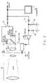
- FIG. 1depicts prior-art day/night cameras, which use dual optical paths and sensors.
- FIG. 2is a day/night camera using one optical path, two sensors, a beam-splitting mirror, and an electrical switch to select the desired camera output.
- FIG. 3depicts the day/night camera of FIG. 2 , with an additional controlled-iris mechanism to provide increased dynamic range.
- FIG. 4depicts the day/night camera of FIG. 2 , with the addition of an image-intensifier device to extend the low-light sensitivity of the system.
- FIG. 5depicts the day/night system of FIG. 4 , with the addition of controlled irises to extend the dynamic range of the system, and to protect the image intensifier mechanism.
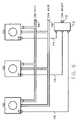
- FIG. 6depicts a multi-imager camera using digital imagers.
- FIG. 7depicts the day/night camera of FIG. 2 , using digital image sensors.
- FIG. 8depicts the digital day/night camera of FIG. 6 , with the addition of an image-intensifier device and dual irises.
- FIG. 9depicts the use of the invention to selectively zoom an image
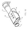
- FIG. 10is an example of a handheld embodiment of the system.
- FIG. 1a prior-art system is depicted, which uses two lenses and sensors to span the desired range of ambient illumination.
- Daylight operationis accomplished using daylight lens 2 and color image sensor 4 .
- Nighttime scenesare captured by lens 6 and image sensor 8 , which is a monochrome area sensor optimized for high sensitivity.
- image sensor 8which is a monochrome area sensor optimized for high sensitivity.
- the overall ambient illuminationis detected by, as an example, a photodiode 3 .
- the resulting signalis buffered by buffer 9 , compared with a reference value by comparator 5 , and used to drive a video source selection relay 7 .
- FIG. 2An enhanced system, subject of the present invention, is depicted in FIG. 2 .
- a single lens 10is used to direct a desired scene onto the sensor optics, consisting of beamsplitting mirror 12 , sensitive monochrome sensor 16 and color sensor 14 .
- the relative positions of the respective sensors 14 and 16may be exchanged, if necessary, without departing from the spirit and scope of the invention.
- the beamsplitting mirror 12is partially reflective, in some proportion designed to optimize the desired optical behavior. For example, if absolute nighttime sensitivity is the highest goal of the design, then the beamsplitter may be 5 percent reflective and 95 percent transmissive, so as to maximize the amount of optical flux that reaches the nighttime sensor.
- the appropriate sensor outputis selected by switch 18 . Note that switch 18 could be automated as depicted in FIG. 1 , through the use of an ambient light level sensor and relay.
- the selected sensor output signal 22is optionally displayed on viewfinder 20 .
- the basic system of FIG. 2is enhanced with a driven iris, which serves to limit the amount of incident light that arrives at the monochrome sensor 16 or, indeed, at the color sensor 14 .
- the overall output video signal 22is sampled by diode 72 , filtered by capacitor 68 , given a time constant via resistor 70 , and applied to iris driver 66 .
- the iris driverdrives the iris actuator 64 and the iris 60 , so as to limit the output signal 22 if it increases to some predetermined level. This serves to limit and stabilize the amount of light incident on the sensors 14 and 16 .
- FIG. 4depicts the basic system of FIG. 2 , as supplemented by the inclusion of an image intensifier 24 . Since the image on the rear surface of the image intensifier is a simple planar image, a relay lens system 26 may be necessary to transfer the image from the rear surface of the intensifier 24 to the monochrome sensor 16 . Other techniques may also be employed to transfer the image, such as the fusion of fiber optic bundles between the intensifier and imager, or direct bonding of the intensifier to the imager.
- FIG. 5depicts an enhancement to the system of FIG. 4 .
- a second iris 80is added, immediately in front of the monochrome sensor 16 .
- This second irisis used to limit the amount of illumination reaching the sensitive monochrome sensor 16 , preventing it from suffering from saturation when the intensifier output image is bright.
- the output signal from the monochrome sensor 16is sampled by diode 90 , filtered by capacitor 86 , given a time constant by resistor 88 , buffered by buffer 84 , and drives the iris 80 via actuator 82 . This effectively stabilizes and limits the output signal from the monochrome sensor 16 .
- This approachfrees the first iris 60 to control the overall output from the system, as depicted earlier in FIG. 3 .
- FIG. 6depicts a multiple-imager version of the system.
- Multiple digital imagers 100 , 102 , and 104share a common address bus 108 and data bus 106 .
- a camera selection signal 110is applied to multiplexer 112 , which thereupon selects one of the sensors via enable lines 114 , 116 , and 118 .
- This methodallows the selection of a desired camera.
- the individual cameras 100 , 102 , and 104may share a common optical path, as in previous examples which use a two-way beamsplitting mirror.
- the individual cameras 100 , 102 , and 104may be separately optimized for different purposes, such as day vs. night, 1 ⁇ zoom vs. 2 ⁇ zoom, etc.
- FIG. 7depicts an enhancement to the basic system of FIG. 2 , wherein the analog sensors are replaced with high-resolution digital sensors 14 (color) and 16 (monochrome).
- a lens system 10directs a desired scene towards the beamsplitter 12 , thence towards the dual image sensors 14 and 16 . Images captured by these digital sensors are transferred to a suitable signal processor 30 with associated program/data memory 32 .
- the processor 30controls the scanning of the selected image sensor 14 or 16 , and produces a corresponding output signal 22 in a desired signal format, such as NTSC, PAL, or a digital format such as D-1.
- a pair of orthogonal gyroscopic accelerometers 34 and 36are disposed in a plane parallel to the image plane of the monochrome sensor 16 .
- Angular accelerations detected by sensors 34 and 36are twice-integrated by processor 30 , to derive a knowledge of the instantaneous angular position of the device. This information is then used to temporally offset the image sensor scanning signals produced by the processor 30 , effectively stabilizing the image position.
- the instantaneous position information previously describedmay be used to variably offset the read addresses driven to the imager or its buffer, again effectively stabilizing the image.
- a variety of user input pushbuttons 38are provided to allow user control of various camera parameters, for instance brightness, stabilization on/off, day/night mode, power on/off, etc.
- An additional benefit of the dual-digital-sensor system of FIG. 7is the ability to scan the imager in reverse-pixel or reverse-line order. This ability overcomes the optical problem imposed by the inclusion of the mirror; images that have been reversed vertically or horizontally by the mirror may be “re-reversed” electronically.
- the monochrome sensor 16is used to provide scene luminance information, while the color sensor 14 is used to provide chrominance information. Note that, since luminance information is provided by sensor 16 , it is possible to use non-traditional color filters on color sensor 14 to increase its resolution and sensitivity. For example, a simple CrCb filter could be used on color sensor 14 , with no pixels wasted for detecting luminance.
- the processor 30may be used to scale and merge the two information streams into one signal. This method is not possible in prior-art systems, which used movable mirrors.
- FIG. 8depicts an enhancement to the digital system of FIG. 7 , wherein the dual-iris arrangement of FIG. 5 is used to optimize the dynamic range of the system.
- incident light reaching monochrome sensor 16is controlled by iris 80 , as driven by actuator 82 under processor control. This effectively prevents the sensitive monochrome imager from suffering saturation or overload.
- the intensifier 24is protected by iris 60 , driven by actuator 64 , also under processor control. This iris serves to protect the intensifier device from excessive illumination.
- the dynamic range of both imagersmay also be improved by the inclusion of automatic gain control, used in conjunction with the irises.
- FIG. 9depicts the use of the invention to achieve selectable ‘zoom’ ratios, or magnifications, without moving optical parts and without reduction of image resolution. While the example in FIG. 9 depicts a pair of digital imagers, analog imagers could be used to the same effect.
- a lens 10captures a desired scene and passes it to an optional image intensifier 24 . The image thereupon passes to a beamsplitting mirror 12 , thence to a pair of imagers 140 and 146 via relay lenses 142 and 144 respectively.
- the relay lensesare selected to have differing magnification ratios. In the example shown, relay lens 142 exhibits a magnification of 1:1, while relay lens 144 exhibits a magnification of 2:1.
- Imager 140 or imager 146may be selected via CAM SELECT signal 152 and inverter 148 . This effectively allows selection of a desired image, or selection of the same image with different magnification.
- lens 140 and imager 142may render a scene 154 , of some given angular field of view. When lens 144 and imager 146 are selected, a smaller field of view 156 is rendered, but at the same resolution as the previous, larger image.
- FIG. 10depicts a preferred embodiment a handheld version of the device.
- a housing 46contains a lens 10 , user controls 38 , eyepiece 42 , battery compartment access panel 46 , and carrying strap 44 .
Landscapes
- Engineering & Computer Science (AREA)
- Multimedia (AREA)
- Signal Processing (AREA)
- Physics & Mathematics (AREA)
- General Physics & Mathematics (AREA)
- Human Computer Interaction (AREA)
- Optics & Photonics (AREA)
- Studio Devices (AREA)
- Transforming Light Signals Into Electric Signals (AREA)
Abstract
Description
Claims (15)
Priority Applications (4)
| Application Number | Priority Date | Filing Date | Title |
|---|---|---|---|
| US09/593,901US7057647B1 (en) | 2000-06-14 | 2000-06-14 | Dual-mode camera system for day/night or variable zoom operation |
| US11/398,508US7551219B2 (en) | 2000-06-14 | 2006-04-05 | Dual-mode camera |
| US11/617,368US7768566B2 (en) | 2000-06-14 | 2006-12-28 | Dual-mode camera |
| US13/903,037US20140354821A1 (en) | 1998-08-28 | 2013-05-28 | Covert Networked Security Camera |
Applications Claiming Priority (1)
| Application Number | Priority Date | Filing Date | Title |
|---|---|---|---|
| US09/593,901US7057647B1 (en) | 2000-06-14 | 2000-06-14 | Dual-mode camera system for day/night or variable zoom operation |
Related Child Applications (2)
| Application Number | Title | Priority Date | Filing Date |
|---|---|---|---|
| US11/398,508DivisionUS7551219B2 (en) | 2000-06-14 | 2006-04-05 | Dual-mode camera |
| US11/617,368DivisionUS7768566B2 (en) | 2000-06-14 | 2006-12-28 | Dual-mode camera |
Publications (1)
| Publication Number | Publication Date |
|---|---|
| US7057647B1true US7057647B1 (en) | 2006-06-06 |
Family
ID=36568949
Family Applications (3)
| Application Number | Title | Priority Date | Filing Date |
|---|---|---|---|
| US09/593,901Expired - Fee RelatedUS7057647B1 (en) | 1998-08-28 | 2000-06-14 | Dual-mode camera system for day/night or variable zoom operation |
| US11/398,508Expired - Fee RelatedUS7551219B2 (en) | 2000-06-14 | 2006-04-05 | Dual-mode camera |
| US11/617,368Expired - Fee RelatedUS7768566B2 (en) | 2000-06-14 | 2006-12-28 | Dual-mode camera |
Family Applications After (2)
| Application Number | Title | Priority Date | Filing Date |
|---|---|---|---|
| US11/398,508Expired - Fee RelatedUS7551219B2 (en) | 2000-06-14 | 2006-04-05 | Dual-mode camera |
| US11/617,368Expired - Fee RelatedUS7768566B2 (en) | 2000-06-14 | 2006-12-28 | Dual-mode camera |
Country Status (1)
| Country | Link |
|---|---|
| US (3) | US7057647B1 (en) |
Cited By (49)
| Publication number | Priority date | Publication date | Assignee | Title |
|---|---|---|---|---|
| US20030048493A1 (en)* | 2001-09-10 | 2003-03-13 | Pontifex Brian Decoursey | Two sensor quantitative low-light color camera |
| US20030160886A1 (en)* | 2002-02-22 | 2003-08-28 | Fuji Photo Film Co., Ltd. | Digital camera |
| US20050046740A1 (en)* | 2003-08-29 | 2005-03-03 | Davis Raymond A.. | Apparatus including a dual camera module and method of using the same |
| US20050140786A1 (en)* | 2003-07-14 | 2005-06-30 | Michael Kaplinsky | Dual spectral band network camera |
| US20050162514A1 (en)* | 2003-06-30 | 2005-07-28 | Dennis Michael R. | Plural-receptor, plural-mode, surveillance imaging system and methodology with task-minimizing, view-establishment control |
| US20050179807A1 (en)* | 2004-02-15 | 2005-08-18 | William Lin | Multiple-sensor camera |
| US20070002028A1 (en)* | 2000-07-05 | 2007-01-04 | Smart Technologies, Inc. | Passive Touch System And Method Of Detecting User Input |
| US20070188629A1 (en)* | 2006-02-14 | 2007-08-16 | Kauzuya Nakabe | Imaging device |
| US20070236454A1 (en)* | 2003-10-09 | 2007-10-11 | Smart Technologies, Inc. | Apparatus For Determining The Location Of A Pointer Within A Region Of Interest |
| US20080030611A1 (en)* | 2006-08-01 | 2008-02-07 | Jenkins Michael V | Dual Sensor Video Camera |
| US7503498B2 (en) | 2003-11-13 | 2009-03-17 | Metrologic Instruments, Inc. | Hand-supportable digital image capturing and processing system employing an area-type image sensing array exposed to illumination from an LED-based illumination array only when all sensor elements in said image-sensing array are activated and in a state of integration |
| US20090278929A1 (en)* | 2008-05-06 | 2009-11-12 | Flir Systems Inc | Video camera with interchangable optical sensors |
| EP2089791A4 (en)* | 2006-12-04 | 2010-09-08 | Smart Technologies Ulc | INTERACTIVE INPUT SYSTEM AND METHOD |
| US20110234638A1 (en)* | 2003-09-16 | 2011-09-29 | Smart Technologies Ulc | Gesture recognition method and touch system incorporating the same |
| US8089462B2 (en) | 2004-01-02 | 2012-01-03 | Smart Technologies Ulc | Pointer tracking across multiple overlapping coordinate input sub-regions defining a generally contiguous input region |
| US8094137B2 (en) | 2007-07-23 | 2012-01-10 | Smart Technologies Ulc | System and method of detecting contact on a display |
| US8115753B2 (en) | 2007-04-11 | 2012-02-14 | Next Holdings Limited | Touch screen system with hover and click input methods |
| US8120596B2 (en) | 2004-05-21 | 2012-02-21 | Smart Technologies Ulc | Tiled touch system |
| US8149221B2 (en) | 2004-05-07 | 2012-04-03 | Next Holdings Limited | Touch panel display system with illumination and detection provided from a single edge |
| US8228304B2 (en) | 2002-11-15 | 2012-07-24 | Smart Technologies Ulc | Size/scale orientation determination of a pointer in a camera-based touch system |
| US8274496B2 (en) | 2004-04-29 | 2012-09-25 | Smart Technologies Ulc | Dual mode touch systems |
| US8289299B2 (en) | 2003-02-14 | 2012-10-16 | Next Holdings Limited | Touch screen signal processing |
| US8339378B2 (en) | 2008-11-05 | 2012-12-25 | Smart Technologies Ulc | Interactive input system with multi-angle reflector |
| US8384693B2 (en) | 2007-08-30 | 2013-02-26 | Next Holdings Limited | Low profile touch panel systems |
| US8405637B2 (en) | 2008-01-07 | 2013-03-26 | Next Holdings Limited | Optical position sensing system and optical position sensor assembly with convex imaging window |
| US8432377B2 (en) | 2007-08-30 | 2013-04-30 | Next Holdings Limited | Optical touchscreen with improved illumination |
| US8456451B2 (en) | 2003-03-11 | 2013-06-04 | Smart Technologies Ulc | System and method for differentiating between pointers used to contact touch surface |
| US8456447B2 (en) | 2003-02-14 | 2013-06-04 | Next Holdings Limited | Touch screen signal processing |
| US8508508B2 (en) | 2003-02-14 | 2013-08-13 | Next Holdings Limited | Touch screen signal processing with single-point calibration |
| US20140125782A1 (en)* | 2005-06-03 | 2014-05-08 | Cedar Crest Partners Inc. | Multi-dimensional imaging system and method |
| US20140211033A1 (en)* | 2012-01-25 | 2014-07-31 | Optex Systems, Inc. | Multiple spectral single image sighting system using single objective lens set |
| US8902193B2 (en) | 2008-05-09 | 2014-12-02 | Smart Technologies Ulc | Interactive input system and bezel therefor |
| EP2630802A4 (en)* | 2010-10-22 | 2015-03-18 | Univ New Brunswick | CAMERA IMAGING SYSTEMS AND METHOD THEREFOR |
| EP2636359A4 (en)* | 2011-08-15 | 2015-03-25 | Olympus Medical Systems Corp | IMAGING DEVICE |
| US9069172B1 (en) | 2010-09-15 | 2015-06-30 | Roland Morley | Multi-mode sight |
| US20160014314A1 (en)* | 2014-07-09 | 2016-01-14 | The Lightco Inc. | Camera device including multiple optical chains and related methods |
| RU2578195C1 (en)* | 2015-01-22 | 2016-03-27 | Вячеслав Михайлович Смелков | Device for panoramic television surveillance "day-night" |
| JP2018518858A (en)* | 2015-03-30 | 2018-07-12 | ノバダック テクノロジーズ インコーポレイテッド | Multi-channel wide-field imaging system and optical system used therein |
| US10057509B2 (en) | 2014-05-30 | 2018-08-21 | Flir Systems, Inc. | Multiple-sensor imaging system |
| CN108605097A (en)* | 2016-11-03 | 2018-09-28 | 华为技术有限公司 | Optical imaging method and its device |
| US10126099B1 (en) | 2017-05-11 | 2018-11-13 | Steiner Eoptics, Inc. | Thermal reflex sight |
| US10656316B2 (en) | 2015-08-31 | 2020-05-19 | Novadaq Technologies ULC | Polarization dependent filter, system using the same, and associated kits and methods |
| CN111556253A (en)* | 2015-07-10 | 2020-08-18 | 深圳市大疆创新科技有限公司 | Method and system for generating combined images, and method and system for displaying images |
| US10798355B2 (en)* | 2014-06-03 | 2020-10-06 | Applied Minds, Llc | Color night vision cameras, systems, and methods thereof |
| US10805600B2 (en) | 2016-07-29 | 2020-10-13 | Applied Minds, Llc | Methods and associated devices and systems for enhanced 2D and 3D vision |
| US10904513B2 (en) | 2010-10-22 | 2021-01-26 | University Of New Brunswick | Camera image fusion methods |
| US10948638B2 (en) | 2014-03-04 | 2021-03-16 | Stryker European Operations Limited | Spatial and spectral filtering apertures and optical imaging systems including the same |
| RU2756915C1 (en)* | 2021-02-17 | 2021-10-07 | Акционерное общество "Московский завод "САПФИР" | Thermovision stereoscopic system |
| US12004716B2 (en) | 2014-03-04 | 2024-06-11 | Stryker Corporation | Relay lens system for broadband imaging |
Families Citing this family (39)
| Publication number | Priority date | Publication date | Assignee | Title |
|---|---|---|---|---|
| US7772533B2 (en)* | 2006-09-25 | 2010-08-10 | Symbol Technologies, Inc. | Multi-sensor image capture device |
| US10298834B2 (en) | 2006-12-01 | 2019-05-21 | Google Llc | Video refocusing |
| US8145004B2 (en)* | 2008-05-27 | 2012-03-27 | Sony Ericsson Mobile Communications Ab | System and method for generating a photograph |
| US8054558B2 (en)* | 2009-02-11 | 2011-11-08 | Omniprobe, Inc. | Multiple magnification optical system with single objective lens |
| US9858649B2 (en) | 2015-09-30 | 2018-01-02 | Lytro, Inc. | Depth-based image blurring |
| JP2014096741A (en)* | 2012-11-12 | 2014-05-22 | Sony Corp | Signal processing circuit, imaging apparatus, and program |
| US9001226B1 (en)* | 2012-12-04 | 2015-04-07 | Lytro, Inc. | Capturing and relighting images using multiple devices |
| US9494787B1 (en)* | 2013-03-12 | 2016-11-15 | Sandia Corporation | Direct view zoom scope with single focal plane and adaptable reticle |
| US10334151B2 (en) | 2013-04-22 | 2019-06-25 | Google Llc | Phase detection autofocus using subaperture images |
| JP2014230179A (en)* | 2013-05-24 | 2014-12-08 | ソニー株式会社 | Imaging apparatus and imaging method |
| CN108989649B (en)* | 2013-08-01 | 2021-03-19 | 核心光电有限公司 | Slim multi-aperture imaging system with autofocus and method of use |
| US10341632B2 (en) | 2015-04-15 | 2019-07-02 | Google Llc. | Spatial random access enabled video system with a three-dimensional viewing volume |
| US10444931B2 (en) | 2017-05-09 | 2019-10-15 | Google Llc | Vantage generation and interactive playback |
| US10419737B2 (en) | 2015-04-15 | 2019-09-17 | Google Llc | Data structures and delivery methods for expediting virtual reality playback |
| US10440407B2 (en) | 2017-05-09 | 2019-10-08 | Google Llc | Adaptive control for immersive experience delivery |
| US10469873B2 (en) | 2015-04-15 | 2019-11-05 | Google Llc | Encoding and decoding virtual reality video |
| US10540818B2 (en) | 2015-04-15 | 2020-01-21 | Google Llc | Stereo image generation and interactive playback |
| US10546424B2 (en) | 2015-04-15 | 2020-01-28 | Google Llc | Layered content delivery for virtual and augmented reality experiences |
| US10565734B2 (en) | 2015-04-15 | 2020-02-18 | Google Llc | Video capture, processing, calibration, computational fiber artifact removal, and light-field pipeline |
| US11328446B2 (en) | 2015-04-15 | 2022-05-10 | Google Llc | Combining light-field data with active depth data for depth map generation |
| US10412373B2 (en) | 2015-04-15 | 2019-09-10 | Google Llc | Image capture for virtual reality displays |
| US10275898B1 (en) | 2015-04-15 | 2019-04-30 | Google Llc | Wedge-based light-field video capture |
| US10567464B2 (en) | 2015-04-15 | 2020-02-18 | Google Llc | Video compression with adaptive view-dependent lighting removal |
| RU2578194C1 (en)* | 2015-05-18 | 2016-03-27 | Вячеслав Михайлович Смелков | Method for panoramic television-computer monitoring (versions) |
| US9979909B2 (en) | 2015-07-24 | 2018-05-22 | Lytro, Inc. | Automatic lens flare detection and correction for light-field images |
| US10539763B2 (en) | 2016-03-31 | 2020-01-21 | Sony Corporation | Optical system, electronic device, camera, method and computer program |
| US10275892B2 (en) | 2016-06-09 | 2019-04-30 | Google Llc | Multi-view scene segmentation and propagation |
| KR102603426B1 (en)* | 2016-06-27 | 2023-11-20 | 삼성전자주식회사 | Apparatus and method for processing an image |
| US10228283B2 (en)* | 2016-08-12 | 2019-03-12 | Spectral Insights Private Limited | Spectral imaging system |
| US10616493B2 (en) | 2016-08-31 | 2020-04-07 | Huawei Technologies Co., Ltd. | Multi camera system for zoom |
| CN107066079A (en)* | 2016-11-29 | 2017-08-18 | 阿里巴巴集团控股有限公司 | Service implementation method and device based on virtual reality scenario |
| US10679361B2 (en) | 2016-12-05 | 2020-06-09 | Google Llc | Multi-view rotoscope contour propagation |
| US10594945B2 (en) | 2017-04-03 | 2020-03-17 | Google Llc | Generating dolly zoom effect using light field image data |
| US10474227B2 (en) | 2017-05-09 | 2019-11-12 | Google Llc | Generation of virtual reality with 6 degrees of freedom from limited viewer data |
| US10354399B2 (en) | 2017-05-25 | 2019-07-16 | Google Llc | Multi-view back-projection to a light-field |
| US10545215B2 (en) | 2017-09-13 | 2020-01-28 | Google Llc | 4D camera tracking and optical stabilization |
| US10965862B2 (en) | 2018-01-18 | 2021-03-30 | Google Llc | Multi-camera navigation interface |
| US12200325B2 (en) | 2020-02-12 | 2025-01-14 | Axon Enterprise, Inc. | Dual mode camera and quasi-bandpass filter |
| DE102022114615A1 (en) | 2022-06-10 | 2023-12-21 | Carl Zeiss Ag | Digital long-range optical device, method for operating a digital long-range optical device and camera system |
Citations (17)
| Publication number | Priority date | Publication date | Assignee | Title |
|---|---|---|---|---|
| US3691302A (en)* | 1971-02-25 | 1972-09-12 | Gte Sylvania Inc | Automatic light control for low light level television camera |
| US3891795A (en)* | 1974-04-11 | 1975-06-24 | Quentin S Johnson | Automatic day-night television surveillance system |
| US4646140A (en)* | 1984-09-25 | 1987-02-24 | English Electric Valve Company Limited | Television cameras |
| US4851914A (en)* | 1987-08-05 | 1989-07-25 | Marco Scientific | High-speed full frame imaging CCD camera |
| WO1990005426A1 (en)* | 1988-11-03 | 1990-05-17 | Pearpoint Limited | T.v. surveillance camera |
| US5013142A (en)* | 1988-12-16 | 1991-05-07 | U.S. Philips Corp. | Bifocal optical system |
| US5373320A (en)* | 1993-05-18 | 1994-12-13 | Intevac, Inc. | Surveillance system having a microchannel image intensifier tube |
| US5398055A (en)* | 1992-07-23 | 1995-03-14 | Sony Corporation | System for detecting stray light |
| US5852502A (en)* | 1996-05-31 | 1998-12-22 | American Digital Imaging, Inc. | Apparatus and method for digital camera and recorder having a high resolution color composite image output |
| US5946132A (en)* | 1991-01-18 | 1999-08-31 | Itt Corporation | Telescopic sight for day/night viewing |
| US5973315A (en)* | 1998-02-18 | 1999-10-26 | Litton Systems, Inc. | Multi-functional day/night observation, ranging, and sighting device with active optical target acquisition and method of its operation |
| US5995141A (en)* | 1994-08-26 | 1999-11-30 | Canon Kabushiki Kaisha | Image pick-up device with a motion detection circuit and a memory control circuit |
| US20020088925A1 (en)* | 1998-08-05 | 2002-07-11 | Microvision, Inc. | Low light viewer with image simulation |
| US6501503B2 (en)* | 1996-05-28 | 2002-12-31 | Canon Kabushiki Kaisha | Image pickup device having means for correcting the motion of an image |
| US6523956B2 (en)* | 2000-05-09 | 2003-02-25 | Jon Oshima | Multiplexed motion picture camera |
| US6590604B1 (en)* | 2000-04-07 | 2003-07-08 | Polycom, Inc. | Personal videoconferencing system having distributed processing architecture |
| US6633333B1 (en)* | 1996-10-02 | 2003-10-14 | Gec-Marconi Ltd. | Cameras |
Family Cites Families (108)
| Publication number | Priority date | Publication date | Assignee | Title |
|---|---|---|---|---|
| US4197526A (en) | 1975-12-03 | 1980-04-08 | Boris Haskell | Miniature pager receiver with digital display and memory |
| US4163283A (en) | 1977-04-11 | 1979-07-31 | Darby Ronald A | Automatic method to identify aircraft types |
| US4179695A (en) | 1978-10-02 | 1979-12-18 | International Telephone And Telegraph Corporation | System for identification of aircraft on airport surface pathways |
| US4516125A (en) | 1982-09-20 | 1985-05-07 | General Signal Corporation | Method and apparatus for monitoring vehicle ground movement in the vicinity of an airport |
| US4845629A (en) | 1985-07-18 | 1989-07-04 | General De Investigacion Y Desarrollo S.A. | Airport surveillance systems |
| US4910692A (en) | 1985-10-09 | 1990-03-20 | Outram John D | Adaptive data logger |
| US4831438A (en) | 1987-02-25 | 1989-05-16 | Household Data Services | Electronic surveillance system |
| WO1988009982A1 (en) | 1987-06-09 | 1988-12-15 | Hiroshi Kawashima | Apparatus for guiding an aircraft on the ground |
| US4891650A (en) | 1988-05-16 | 1990-01-02 | Trackmobile Inc. | Vehicle location system |
| US4857912A (en) | 1988-07-27 | 1989-08-15 | The United States Of America As Represented By The Secretary Of The Navy | Intelligent security assessment system |
| SE462698B (en) | 1988-10-07 | 1990-08-13 | Swedish Airport Technology Han | FAIR LIGHTING FOR AIRPORT |
| ATE139802T1 (en)* | 1989-01-05 | 1996-07-15 | Leti Lab | USE OF SPECIFIC PROPERTIES OF ANIMAL ALLERGENS AND METHOD FOR THEIR PRODUCTION |
| AU4826090A (en) | 1989-01-16 | 1990-08-13 | Christopher Francis Coles | Photographic security system |
| DE69021326T2 (en) | 1989-11-07 | 1996-01-11 | Konishiroku Photo Ind | Imaging unit with a belt. |
| US5085662A (en)* | 1989-11-13 | 1992-02-04 | Scimed Life Systems, Inc. | Atherectomy catheter and related components |
| US5027104A (en) | 1990-02-21 | 1991-06-25 | Reid Donald J | Vehicle security device |
| US5091780A (en) | 1990-05-09 | 1992-02-25 | Carnegie-Mellon University | A trainable security system emthod for the same |
| JP2667924B2 (en) | 1990-05-25 | 1997-10-27 | 東芝テスコ 株式会社 | Aircraft docking guidance device |
| US5109278A (en) | 1990-07-06 | 1992-04-28 | Commonwealth Edison Company | Auto freeze frame display for intrusion monitoring system |
| US6195609B1 (en) | 1993-09-07 | 2001-02-27 | Harold Robert Pilley | Method and system for the control and management of an airport |
| US5867804A (en) | 1993-09-07 | 1999-02-02 | Harold R. Pilley | Method and system for the control and management of a three dimensional space envelope |
| JPH07115677B2 (en) | 1990-10-30 | 1995-12-13 | 嘉三 藤本 | Flight information recording method and apparatus for aircraft |
| DE69125171D1 (en) | 1990-12-11 | 1997-04-17 | Forecourt Security Dev | SYSTEM FOR SECURING VEHICLES ON A PARKING LOT |
| NZ240907A (en) | 1990-12-14 | 1995-01-27 | Ainsworth Tech Inc | Communication system: signal level adjusting interface between distribution and antenna systems |
| US5408330A (en) | 1991-03-25 | 1995-04-18 | Crimtec Corporation | Video incident capture system |
| US5243530A (en) | 1991-07-26 | 1993-09-07 | The United States Of America As Represented By The Secretary Of The Navy | Stand alone multiple unit tracking system |
| US5375058A (en) | 1991-12-20 | 1994-12-20 | University Of Central Florida | Surface detection system for airports |
| US5448243A (en) | 1991-12-30 | 1995-09-05 | Deutsche Forschungsanstalt Fur Luft- Und Raumfahrt E.V. | System for locating a plurality of objects and obstructions and for detecting and determining the rolling status of moving objects, such as aircraft, ground vehicles, and the like |
| US6226031B1 (en) | 1992-02-19 | 2001-05-01 | Netergy Networks, Inc. | Video communication/monitoring apparatus and method therefor |
| GB2267625B (en) | 1992-05-20 | 1996-08-21 | Northern Telecom Ltd | Video services |
| US5218367A (en) | 1992-06-01 | 1993-06-08 | Trackmobile | Vehicle tracking system |
| US5268698A (en) | 1992-07-31 | 1993-12-07 | Smith Sr Louis P | Target acquisition, locating and tracking system |
| US5636122A (en) | 1992-10-16 | 1997-06-03 | Mobile Information Systems, Inc. | Method and apparatus for tracking vehicle location and computer aided dispatch |
| US5777580A (en) | 1992-11-18 | 1998-07-07 | Trimble Navigation Limited | Vehicle location system |
| US6675386B1 (en) | 1996-09-04 | 2004-01-06 | Discovery Communications, Inc. | Apparatus for video access and control over computer network, including image correction |
| US5321615A (en) | 1992-12-10 | 1994-06-14 | Frisbie Marvin E | Zero visibility surface traffic control system |
| US5530440A (en) | 1992-12-15 | 1996-06-25 | Westinghouse Norden Systems, Inc | Airport surface aircraft locator |
| US5714948A (en) | 1993-05-14 | 1998-02-03 | Worldwide Notifications Systems, Inc. | Satellite based aircraft traffic control system |
| US5508736A (en) | 1993-05-14 | 1996-04-16 | Cooper; Roger D. | Video signal processing apparatus for producing a composite signal for simultaneous display of data and video information |
| US5334982A (en) | 1993-05-27 | 1994-08-02 | Norden Systems, Inc. | Airport surface vehicle identification |
| US5917405A (en) | 1993-06-08 | 1999-06-29 | Joao; Raymond Anthony | Control apparatus and methods for vehicles |
| US5983161A (en) | 1993-08-11 | 1999-11-09 | Lemelson; Jerome H. | GPS vehicle collision avoidance warning and control system and method |
| US5497149A (en) | 1993-09-02 | 1996-03-05 | Fast; Ray | Global security system |
| US5463595A (en) | 1993-10-13 | 1995-10-31 | Rodhall; Arne | Portable security system for outdoor sites |
| US5440337A (en) | 1993-11-12 | 1995-08-08 | Puritan-Bennett Corporation | Multi-camera closed circuit television system for aircraft |
| US5557254A (en) | 1993-11-16 | 1996-09-17 | Mobile Security Communications, Inc. | Programmable vehicle monitoring and security system having multiple access verification devices |
| JP3427454B2 (en)* | 1993-12-21 | 2003-07-14 | 株式会社ニコン | Still camera |
| WO1995021511A1 (en) | 1994-02-07 | 1995-08-10 | Harold Ii Pace | Mobile location reporting apparatus and methods |
| US5440343A (en) | 1994-02-28 | 1995-08-08 | Eastman Kodak Company | Motion/still electronic image sensing apparatus |
| US5400031A (en) | 1994-03-07 | 1995-03-21 | Norden Systems, Inc. | Airport surface vehicle identification system and method |
| DE69514980T2 (en) | 1994-05-06 | 2000-10-05 | Koninklijke Philips Electronics N.V., Eindhoven | METHOD AND DEVICE FOR DIFFERENTIAL VEHICLE LOCATION UNDER CONTROL OF AN INTERNAL STATUS CHANGE |
| US5850180A (en) | 1994-09-09 | 1998-12-15 | Tattletale Portable Alarm Systems, Inc. | Portable alarm system |
| US5777551A (en) | 1994-09-09 | 1998-07-07 | Hess; Brian K. | Portable alarm system |
| JPH08146130A (en) | 1994-11-24 | 1996-06-07 | Mitsubishi Electric Corp | Airport surface ground control system |
| US5666157A (en) | 1995-01-03 | 1997-09-09 | Arc Incorporated | Abnormality detection and surveillance system |
| US5642285A (en) | 1995-01-31 | 1997-06-24 | Trimble Navigation Limited | Outdoor movie camera GPS-position and time code data-logging for special effects production |
| US5553609A (en) | 1995-02-09 | 1996-09-10 | Visiting Nurse Service, Inc. | Intelligent remote visual monitoring system for home health care service |
| US5751346A (en) | 1995-02-10 | 1998-05-12 | Dozier Financial Corporation | Image retention and information security system |
| US5689442A (en) | 1995-03-22 | 1997-11-18 | Witness Systems, Inc. | Event surveillance system |
| US5629691A (en) | 1995-05-26 | 1997-05-13 | Hughes Electronics | Airport surface monitoring and runway incursion warning system |
| US5557278A (en) | 1995-06-23 | 1996-09-17 | Northrop Grumman Corporation | Airport integrated hazard response apparatus |
| US5627753A (en) | 1995-06-26 | 1997-05-06 | Patriot Sensors And Controls Corporation | Method and apparatus for recording data on cockpit voice recorder |
| US5926210A (en) | 1995-07-28 | 1999-07-20 | Kalatel, Inc. | Mobile, ground-based platform security system which transmits images that were taken prior to the generation of an input signal |
| US5835059A (en) | 1995-09-01 | 1998-11-10 | Lockheed Martin Corporation | Data link and method |
| US5793416A (en) | 1995-12-29 | 1998-08-11 | Lsi Logic Corporation | Wireless system for the communication of audio, video and data signals over a narrow bandwidth |
| CN1103092C (en) | 1996-02-29 | 2003-03-12 | 西门子公司 | Airport guidance system, in particular airport surface movement guidance and control system |
| US6587046B2 (en) | 1996-03-27 | 2003-07-01 | Raymond Anthony Joao | Monitoring apparatus and method |
| US5974158A (en) | 1996-03-29 | 1999-10-26 | The Commonwealth Of Australia Commonwealth Scientific And Industrial Research Organization | Aircraft detection system |
| US5825283A (en) | 1996-07-03 | 1998-10-20 | Camhi; Elie | System for the security and auditing of persons and property |
| US5938706A (en) | 1996-07-08 | 1999-08-17 | Feldman; Yasha I. | Multi element security system |
| JP3862321B2 (en) | 1996-07-23 | 2006-12-27 | キヤノン株式会社 | Server and control method thereof |
| US6525761B2 (en) | 1996-07-23 | 2003-02-25 | Canon Kabushiki Kaisha | Apparatus and method for controlling a camera connected to a network |
| US7113971B1 (en) | 1996-08-05 | 2006-09-26 | Canon Kabushiki Kaisha | Communication method and apparatus, server and client on network, and program codes realizing communication thereof |
| US6259475B1 (en) | 1996-10-07 | 2001-07-10 | H. V. Technology, Inc. | Video and audio transmission apparatus for vehicle surveillance system |
| US5798458A (en) | 1996-10-11 | 1998-08-25 | Raytheon Ti Systems, Inc. | Acoustic catastrophic event detection and data capture and retrieval system for aircraft |
| JP3548352B2 (en) | 1996-10-25 | 2004-07-28 | キヤノン株式会社 | Remote camera control system, apparatus and method |
| US6157317A (en) | 1996-12-02 | 2000-12-05 | Kline And Walker Llc | Secure communication and control system for monitoring, recording, reporting and/or restricting unauthorized use of vehicle. |
| US5742336A (en) | 1996-12-16 | 1998-04-21 | Lee; Frederick A. | Aircraft surveillance and recording system |
| US5933098A (en) | 1997-03-21 | 1999-08-03 | Haxton; Phil | Aircraft security system and method |
| US6084510A (en) | 1997-04-18 | 2000-07-04 | Lemelson; Jerome H. | Danger warning and emergency response system and method |
| FR2763727B1 (en) | 1997-05-20 | 1999-08-13 | Sagem | METHOD AND SYSTEM FOR GUIDING AN AIRPLANE TOWARDS A BERTH |
| US6092008A (en) | 1997-06-13 | 2000-07-18 | Bateman; Wesley H. | Flight event record system |
| JP3085252B2 (en) | 1997-07-31 | 2000-09-04 | 日本電気株式会社 | Remote control camera video relay system |
| US6275231B1 (en) | 1997-08-01 | 2001-08-14 | American Calcar Inc. | Centralized control and management system for automobiles |
| US6069655A (en) | 1997-08-01 | 2000-05-30 | Wells Fargo Alarm Services, Inc. | Advanced video security system |
| US6002427A (en) | 1997-09-15 | 1999-12-14 | Kipust; Alan J. | Security system with proximity sensing for an electronic device |
| US6570610B1 (en) | 1997-09-15 | 2003-05-27 | Alan Kipust | Security system with proximity sensing for an electronic device |
| US6930709B1 (en) | 1997-12-04 | 2005-08-16 | Pentax Of America, Inc. | Integrated internet/intranet camera |
| AU2652299A (en) | 1998-01-09 | 1999-07-26 | Orincon Technologies, Inc. | System and method for classifying and tracking aircraft and vehicles on the grounds of an airport |
| US6078850A (en) | 1998-03-03 | 2000-06-20 | International Business Machines Corporation | Method and apparatus for fuel management and for preventing fuel spillage |
| US6385772B1 (en) | 1998-04-30 | 2002-05-07 | Texas Instruments Incorporated | Monitoring system having wireless remote viewing and control |
| US6278965B1 (en) | 1998-06-04 | 2001-08-21 | The United States Of America As Represented By The Administrator Of The National Aeronautics And Space Administration | Real-time surface traffic adviser |
| US6522352B1 (en) | 1998-06-22 | 2003-02-18 | Motorola, Inc. | Self-contained wireless camera device, wireless camera system and method |
| US5999116A (en) | 1998-07-14 | 1999-12-07 | Rannoch Corporation | Method and apparatus for improving the surveillance coverage and target identification in a radar based surveillance system |
| US6628835B1 (en) | 1998-08-31 | 2003-09-30 | Texas Instruments Incorporated | Method and system for defining and recognizing complex events in a video sequence |
| US6292098B1 (en) | 1998-08-31 | 2001-09-18 | Hitachi, Ltd. | Surveillance system and network system |
| JP3443341B2 (en)* | 1998-10-19 | 2003-09-02 | 三洋電機株式会社 | Digital camera |
| IT1302866B1 (en) | 1998-11-13 | 2000-10-10 | Telecom Italia Spa | ENVIRONMENTAL MONITORING APPARATUS ON TELEPHONE NETWORK. |
| US6154658A (en) | 1998-12-14 | 2000-11-28 | Lockheed Martin Corporation | Vehicle information and safety control system |
| US6720990B1 (en) | 1998-12-28 | 2004-04-13 | Walker Digital, Llc | Internet surveillance system and method |
| US6246320B1 (en) | 1999-02-25 | 2001-06-12 | David A. Monroe | Ground link with on-board security surveillance system for aircraft and other commercial vehicles |
| US6662649B1 (en) | 1999-03-19 | 2003-12-16 | Simmons Sirvey Corporation | Material level monitoring and reporting |
| US6476858B1 (en) | 1999-08-12 | 2002-11-05 | Innovation Institute | Video monitoring and security system |
| US6424370B1 (en) | 1999-10-08 | 2002-07-23 | Texas Instruments Incorporated | Motion based event detection system and method |
| US6698021B1 (en) | 1999-10-12 | 2004-02-24 | Vigilos, Inc. | System and method for remote control of surveillance devices |
| AU1806601A (en) | 1999-11-30 | 2001-06-12 | New Media Technology, Corp. | System and method for computer-assisted manual and automatic logging of time-based media |
| US6646676B1 (en) | 2000-05-17 | 2003-11-11 | Mitsubishi Electric Research Laboratories, Inc. | Networked surveillance and control system |
| US6504479B1 (en) | 2000-09-07 | 2003-01-07 | Comtrak Technologies Llc | Integrated security system |
- 2000
- 2000-06-14USUS09/593,901patent/US7057647B1/ennot_activeExpired - Fee Related
- 2006
- 2006-04-05USUS11/398,508patent/US7551219B2/ennot_activeExpired - Fee Related
- 2006-12-28USUS11/617,368patent/US7768566B2/ennot_activeExpired - Fee Related
Patent Citations (17)
| Publication number | Priority date | Publication date | Assignee | Title |
|---|---|---|---|---|
| US3691302A (en)* | 1971-02-25 | 1972-09-12 | Gte Sylvania Inc | Automatic light control for low light level television camera |
| US3891795A (en)* | 1974-04-11 | 1975-06-24 | Quentin S Johnson | Automatic day-night television surveillance system |
| US4646140A (en)* | 1984-09-25 | 1987-02-24 | English Electric Valve Company Limited | Television cameras |
| US4851914A (en)* | 1987-08-05 | 1989-07-25 | Marco Scientific | High-speed full frame imaging CCD camera |
| WO1990005426A1 (en)* | 1988-11-03 | 1990-05-17 | Pearpoint Limited | T.v. surveillance camera |
| US5013142A (en)* | 1988-12-16 | 1991-05-07 | U.S. Philips Corp. | Bifocal optical system |
| US5946132A (en)* | 1991-01-18 | 1999-08-31 | Itt Corporation | Telescopic sight for day/night viewing |
| US5398055A (en)* | 1992-07-23 | 1995-03-14 | Sony Corporation | System for detecting stray light |
| US5373320A (en)* | 1993-05-18 | 1994-12-13 | Intevac, Inc. | Surveillance system having a microchannel image intensifier tube |
| US5995141A (en)* | 1994-08-26 | 1999-11-30 | Canon Kabushiki Kaisha | Image pick-up device with a motion detection circuit and a memory control circuit |
| US6501503B2 (en)* | 1996-05-28 | 2002-12-31 | Canon Kabushiki Kaisha | Image pickup device having means for correcting the motion of an image |
| US5852502A (en)* | 1996-05-31 | 1998-12-22 | American Digital Imaging, Inc. | Apparatus and method for digital camera and recorder having a high resolution color composite image output |
| US6633333B1 (en)* | 1996-10-02 | 2003-10-14 | Gec-Marconi Ltd. | Cameras |
| US5973315A (en)* | 1998-02-18 | 1999-10-26 | Litton Systems, Inc. | Multi-functional day/night observation, ranging, and sighting device with active optical target acquisition and method of its operation |
| US20020088925A1 (en)* | 1998-08-05 | 2002-07-11 | Microvision, Inc. | Low light viewer with image simulation |
| US6590604B1 (en)* | 2000-04-07 | 2003-07-08 | Polycom, Inc. | Personal videoconferencing system having distributed processing architecture |
| US6523956B2 (en)* | 2000-05-09 | 2003-02-25 | Jon Oshima | Multiplexed motion picture camera |
Cited By (69)
| Publication number | Priority date | Publication date | Assignee | Title |
|---|---|---|---|---|
| US8055022B2 (en) | 2000-07-05 | 2011-11-08 | Smart Technologies Ulc | Passive touch system and method of detecting user input |
| US8203535B2 (en) | 2000-07-05 | 2012-06-19 | Smart Technologies Ulc | Passive touch system and method of detecting user input |
| US20070002028A1 (en)* | 2000-07-05 | 2007-01-04 | Smart Technologies, Inc. | Passive Touch System And Method Of Detecting User Input |
| US20090153523A1 (en)* | 2000-07-05 | 2009-06-18 | Smart Technologies Ulc | Passive touch system and method of detecting user input |
| US20030048493A1 (en)* | 2001-09-10 | 2003-03-13 | Pontifex Brian Decoursey | Two sensor quantitative low-light color camera |
| US20030160886A1 (en)* | 2002-02-22 | 2003-08-28 | Fuji Photo Film Co., Ltd. | Digital camera |
| US8098287B2 (en)* | 2002-02-22 | 2012-01-17 | Fujifilm Corporation | Digital camera with a number of photographing systems |
| US8228304B2 (en) | 2002-11-15 | 2012-07-24 | Smart Technologies Ulc | Size/scale orientation determination of a pointer in a camera-based touch system |
| US8508508B2 (en) | 2003-02-14 | 2013-08-13 | Next Holdings Limited | Touch screen signal processing with single-point calibration |
| US8466885B2 (en) | 2003-02-14 | 2013-06-18 | Next Holdings Limited | Touch screen signal processing |
| US8289299B2 (en) | 2003-02-14 | 2012-10-16 | Next Holdings Limited | Touch screen signal processing |
| US8456447B2 (en) | 2003-02-14 | 2013-06-04 | Next Holdings Limited | Touch screen signal processing |
| US8456451B2 (en) | 2003-03-11 | 2013-06-04 | Smart Technologies Ulc | System and method for differentiating between pointers used to contact touch surface |
| US20050162514A1 (en)* | 2003-06-30 | 2005-07-28 | Dennis Michael R. | Plural-receptor, plural-mode, surveillance imaging system and methodology with task-minimizing, view-establishment control |
| US7492390B2 (en)* | 2003-07-14 | 2009-02-17 | Arecont Vision, Llc. | Dual spectral band network camera |
| US20050140786A1 (en)* | 2003-07-14 | 2005-06-30 | Michael Kaplinsky | Dual spectral band network camera |
| US7619683B2 (en)* | 2003-08-29 | 2009-11-17 | Aptina Imaging Corporation | Apparatus including a dual camera module and method of using the same |
| US20050046740A1 (en)* | 2003-08-29 | 2005-03-03 | Davis Raymond A.. | Apparatus including a dual camera module and method of using the same |
| US20110234638A1 (en)* | 2003-09-16 | 2011-09-29 | Smart Technologies Ulc | Gesture recognition method and touch system incorporating the same |
| US8325134B2 (en) | 2003-09-16 | 2012-12-04 | Smart Technologies Ulc | Gesture recognition method and touch system incorporating the same |
| US8456418B2 (en) | 2003-10-09 | 2013-06-04 | Smart Technologies Ulc | Apparatus for determining the location of a pointer within a region of interest |
| US20070236454A1 (en)* | 2003-10-09 | 2007-10-11 | Smart Technologies, Inc. | Apparatus For Determining The Location Of A Pointer Within A Region Of Interest |
| US7503498B2 (en) | 2003-11-13 | 2009-03-17 | Metrologic Instruments, Inc. | Hand-supportable digital image capturing and processing system employing an area-type image sensing array exposed to illumination from an LED-based illumination array only when all sensor elements in said image-sensing array are activated and in a state of integration |
| US8089462B2 (en) | 2004-01-02 | 2012-01-03 | Smart Technologies Ulc | Pointer tracking across multiple overlapping coordinate input sub-regions defining a generally contiguous input region |
| US20050179807A1 (en)* | 2004-02-15 | 2005-08-18 | William Lin | Multiple-sensor camera |
| US8274496B2 (en) | 2004-04-29 | 2012-09-25 | Smart Technologies Ulc | Dual mode touch systems |
| US8149221B2 (en) | 2004-05-07 | 2012-04-03 | Next Holdings Limited | Touch panel display system with illumination and detection provided from a single edge |
| US8120596B2 (en) | 2004-05-21 | 2012-02-21 | Smart Technologies Ulc | Tiled touch system |
| US20140125782A1 (en)* | 2005-06-03 | 2014-05-08 | Cedar Crest Partners Inc. | Multi-dimensional imaging system and method |
| US20070188629A1 (en)* | 2006-02-14 | 2007-08-16 | Kauzuya Nakabe | Imaging device |
| US7724297B2 (en)* | 2006-02-14 | 2010-05-25 | Olympus Imaging Corp. | Imaging device having a display to display images captured by a plurality of image sensors with different display regions |
| US20080030611A1 (en)* | 2006-08-01 | 2008-02-07 | Jenkins Michael V | Dual Sensor Video Camera |
| US7667762B2 (en)* | 2006-08-01 | 2010-02-23 | Lifesize Communications, Inc. | Dual sensor video camera |
| US9442607B2 (en) | 2006-12-04 | 2016-09-13 | Smart Technologies Inc. | Interactive input system and method |
| EP2089791A4 (en)* | 2006-12-04 | 2010-09-08 | Smart Technologies Ulc | INTERACTIVE INPUT SYSTEM AND METHOD |
| US8115753B2 (en) | 2007-04-11 | 2012-02-14 | Next Holdings Limited | Touch screen system with hover and click input methods |
| US8094137B2 (en) | 2007-07-23 | 2012-01-10 | Smart Technologies Ulc | System and method of detecting contact on a display |
| US8432377B2 (en) | 2007-08-30 | 2013-04-30 | Next Holdings Limited | Optical touchscreen with improved illumination |
| US8384693B2 (en) | 2007-08-30 | 2013-02-26 | Next Holdings Limited | Low profile touch panel systems |
| US8405637B2 (en) | 2008-01-07 | 2013-03-26 | Next Holdings Limited | Optical position sensing system and optical position sensor assembly with convex imaging window |
| US8405636B2 (en) | 2008-01-07 | 2013-03-26 | Next Holdings Limited | Optical position sensing system and optical position sensor assembly |
| US20090278929A1 (en)* | 2008-05-06 | 2009-11-12 | Flir Systems Inc | Video camera with interchangable optical sensors |
| US8902193B2 (en) | 2008-05-09 | 2014-12-02 | Smart Technologies Ulc | Interactive input system and bezel therefor |
| US8339378B2 (en) | 2008-11-05 | 2012-12-25 | Smart Technologies Ulc | Interactive input system with multi-angle reflector |
| US9069172B1 (en) | 2010-09-15 | 2015-06-30 | Roland Morley | Multi-mode sight |
| EP2630802A4 (en)* | 2010-10-22 | 2015-03-18 | Univ New Brunswick | CAMERA IMAGING SYSTEMS AND METHOD THEREFOR |
| US10904513B2 (en) | 2010-10-22 | 2021-01-26 | University Of New Brunswick | Camera image fusion methods |
| EP2636359A4 (en)* | 2011-08-15 | 2015-03-25 | Olympus Medical Systems Corp | IMAGING DEVICE |
| US20140211033A1 (en)* | 2012-01-25 | 2014-07-31 | Optex Systems, Inc. | Multiple spectral single image sighting system using single objective lens set |
| US10948638B2 (en) | 2014-03-04 | 2021-03-16 | Stryker European Operations Limited | Spatial and spectral filtering apertures and optical imaging systems including the same |
| US12004716B2 (en) | 2014-03-04 | 2024-06-11 | Stryker Corporation | Relay lens system for broadband imaging |
| US10057509B2 (en) | 2014-05-30 | 2018-08-21 | Flir Systems, Inc. | Multiple-sensor imaging system |
| US12167182B2 (en) | 2014-06-03 | 2024-12-10 | Applied Minds, Llc | Color night vision cameras, systems, and methods thereof |
| US11553165B2 (en) | 2014-06-03 | 2023-01-10 | Applied Minds, Llc | Color night vision cameras, systems, and methods thereof |
| US11889239B2 (en) | 2014-06-03 | 2024-01-30 | Applied Minds, Llc | Color night vision cameras, systems, and methods thereof |
| US10798355B2 (en)* | 2014-06-03 | 2020-10-06 | Applied Minds, Llc | Color night vision cameras, systems, and methods thereof |
| US20160014314A1 (en)* | 2014-07-09 | 2016-01-14 | The Lightco Inc. | Camera device including multiple optical chains and related methods |
| US10110794B2 (en)* | 2014-07-09 | 2018-10-23 | Light Labs Inc. | Camera device including multiple optical chains and related methods |
| RU2578195C1 (en)* | 2015-01-22 | 2016-03-27 | Вячеслав Михайлович Смелков | Device for panoramic television surveillance "day-night" |
| JP2018518858A (en)* | 2015-03-30 | 2018-07-12 | ノバダック テクノロジーズ インコーポレイテッド | Multi-channel wide-field imaging system and optical system used therein |
| CN111556253A (en)* | 2015-07-10 | 2020-08-18 | 深圳市大疆创新科技有限公司 | Method and system for generating combined images, and method and system for displaying images |
| US10656316B2 (en) | 2015-08-31 | 2020-05-19 | Novadaq Technologies ULC | Polarization dependent filter, system using the same, and associated kits and methods |
| US10805600B2 (en) | 2016-07-29 | 2020-10-13 | Applied Minds, Llc | Methods and associated devices and systems for enhanced 2D and 3D vision |
| US11363251B2 (en) | 2016-07-29 | 2022-06-14 | Applied Minds, Llc | Methods and associated devices and systems for enhanced 2D and 3D vision |
| US11930156B2 (en) | 2016-07-29 | 2024-03-12 | Applied Minds, Llc | Methods and associated devices and systems for enhanced 2D and 3D vision |
| US10810720B2 (en) | 2016-11-03 | 2020-10-20 | Huawei Technologies Co., Ltd. | Optical imaging method and apparatus |
| CN108605097A (en)* | 2016-11-03 | 2018-09-28 | 华为技术有限公司 | Optical imaging method and its device |
| US10126099B1 (en) | 2017-05-11 | 2018-11-13 | Steiner Eoptics, Inc. | Thermal reflex sight |
| RU2756915C1 (en)* | 2021-02-17 | 2021-10-07 | Акционерное общество "Московский завод "САПФИР" | Thermovision stereoscopic system |
Also Published As
| Publication number | Publication date |
|---|---|
| US20070052810A1 (en) | 2007-03-08 |
| US7551219B2 (en) | 2009-06-23 |
| US20070182840A1 (en) | 2007-08-09 |
| US7768566B2 (en) | 2010-08-03 |
Similar Documents
| Publication | Publication Date | Title |
|---|---|---|
| US7057647B1 (en) | Dual-mode camera system for day/night or variable zoom operation | |
| US20070126920A1 (en) | Cameras capable of focus adjusting | |
| US8437084B2 (en) | Optical low-pass filter | |
| KR20040070840A (en) | Infrared camera having auto-focusing in day and night, and method for auto-focusing thereof | |
| US8908068B2 (en) | Image pickup device and image pickup unit to form composite image | |
| KR20060042312A (en) | Apparatus and Method for Eliminating Fixed Pattern Noise in Digital Cameras | |
| US5541705A (en) | Camera with large dynamic range | |
| CN102023458B (en) | Imaging apparatus | |
| GB2354901A (en) | Colour image capturing device | |
| JPH05110938A (en) | Lens unit for television camera | |
| TWI344787B (en) | ||
| US20050099525A1 (en) | Telescope main body and telescope | |
| JP2011130138A (en) | Imaging apparatus, and optical system of the same | |
| US4623932A (en) | Video camera having an automatic focusing system | |
| US20050099683A1 (en) | Telescope, telescope main body and electronic view finder | |
| US11122196B2 (en) | Image processing apparatus | |
| JP2004186721A (en) | Camera | |
| JP4674424B2 (en) | Imaging system | |
| US20090079861A1 (en) | Digital Camera with Interchangeable Lens and an Electronic Viewfinder | |
| JPH0214675A (en) | Electronic image pickup device | |
| US20050078360A1 (en) | Telescope body and telescope provided with the telescope body | |
| US20050099524A1 (en) | Optical instrument with digital camera | |
| JPH05260357A (en) | Image pickup device | |
| JPH0723404A (en) | Video camera equipment | |
| JP4157465B2 (en) | Zoom eyepiece and telescope |
Legal Events
| Date | Code | Title | Description |
|---|---|---|---|
| AS | Assignment | Owner name:E-WATCH, INC., TEXAS Free format text:ASSIGNMENT OF ASSIGNORS INTEREST;ASSIGNOR:TELESIS GROUP, INC., THE;REEL/FRAME:016824/0514 Effective date:20050609 | |
| AS | Assignment | Owner name:TELESIS GROUP, INC., THE, TEXAS Free format text:ASSIGNMENT OF ASSIGNORS INTEREST;ASSIGNOR:MONROE, DAVID A.;REEL/FRAME:016722/0239 Effective date:20050609 | |
| REMI | Maintenance fee reminder mailed | ||
| FPAY | Fee payment | Year of fee payment:4 | |
| SULP | Surcharge for late payment | ||
| FEPP | Fee payment procedure | Free format text:PETITION RELATED TO MAINTENANCE FEES GRANTED (ORIGINAL EVENT CODE: PMFG); ENTITY STATUS OF PATENT OWNER: SMALL ENTITY Free format text:PAT HOLDER CLAIMS SMALL ENTITY STATUS, ENTITY STATUS SET TO SMALL (ORIGINAL EVENT CODE: LTOS); ENTITY STATUS OF PATENT OWNER: SMALL ENTITY Free format text:PETITION RELATED TO MAINTENANCE FEES FILED (ORIGINAL EVENT CODE: PMFP); ENTITY STATUS OF PATENT OWNER: SMALL ENTITY | |
| REMI | Maintenance fee reminder mailed | ||
| PRDP | Patent reinstated due to the acceptance of a late maintenance fee | Effective date:20140610 | |
| FPAY | Fee payment | Year of fee payment:8 | |
| AS | Assignment | Owner name:CLYDE B. AND PEGGY SMITH, TEXAS Free format text:SECURITY INTEREST;ASSIGNOR:E-WATCH, INC.;REEL/FRAME:037714/0835 Effective date:20140325 | |
| FEPP | Fee payment procedure | Free format text:MAINTENANCE FEE REMINDER MAILED (ORIGINAL EVENT CODE: REM.) | |
| LAPS | Lapse for failure to pay maintenance fees | Free format text:PATENT EXPIRED FOR FAILURE TO PAY MAINTENANCE FEES (ORIGINAL EVENT CODE: EXP.) | |
| STCH | Information on status: patent discontinuation | Free format text:PATENT EXPIRED DUE TO NONPAYMENT OF MAINTENANCE FEES UNDER 37 CFR 1.362 | |
| FP | Lapsed due to failure to pay maintenance fee | Effective date:20180606 |