US7057500B1 - Rear view monitoring system for motor vehicles - Google Patents
Rear view monitoring system for motor vehiclesDownload PDFInfo
- Publication number
- US7057500B1 US7057500B1US10/830,077US83007704AUS7057500B1US 7057500 B1US7057500 B1US 7057500B1US 83007704 AUS83007704 AUS 83007704AUS 7057500 B1US7057500 B1US 7057500B1
- Authority
- US
- United States
- Prior art keywords
- vehicle
- image
- monitoring system
- video
- mirror
- Prior art date
- Legal status (The legal status is an assumption and is not a legal conclusion. Google has not performed a legal analysis and makes no representation as to the accuracy of the status listed.)
- Expired - Fee Related, expires
Links
- 238000012544monitoring processMethods0.000titleclaimsabstractdescription24
- 230000000712assemblyEffects0.000claimsabstractdescription24
- 238000000429assemblyMethods0.000claimsabstractdescription24
- 230000003287optical effectEffects0.000claimsabstractdescription6
- 230000005540biological transmissionEffects0.000claimsabstractdescription3
- 239000004020conductorSubstances0.000claimsabstract2
- 238000012806monitoring deviceMethods0.000claimsdescription5
- 230000004075alterationEffects0.000claimsdescription2
- 230000002452interceptive effectEffects0.000claimsdescription2
- 238000010276constructionMethods0.000claims1
- 230000000007visual effectEffects0.000description3
- 230000000694effectsEffects0.000description2
- 238000003384imaging methodMethods0.000description2
- 238000013459approachMethods0.000description1
- 230000009286beneficial effectEffects0.000description1
- 239000002131composite materialSubstances0.000description1
- 230000001419dependent effectEffects0.000description1
- 238000013461designMethods0.000description1
- 230000003467diminishing effectEffects0.000description1
- 230000002708enhancing effectEffects0.000description1
- 238000012423maintenanceMethods0.000description1
- 239000000203mixtureSubstances0.000description1
- 238000012986modificationMethods0.000description1
- 230000004048modificationEffects0.000description1
- 230000007935neutral effectEffects0.000description1
- 230000001681protective effectEffects0.000description1
- 230000003678scratch resistant effectEffects0.000description1
- 238000012800visualizationMethods0.000description1
Images


Classifications
- H—ELECTRICITY
- H04—ELECTRIC COMMUNICATION TECHNIQUE
- H04N—PICTORIAL COMMUNICATION, e.g. TELEVISION
- H04N7/00—Television systems
- H04N7/18—Closed-circuit television [CCTV] systems, i.e. systems in which the video signal is not broadcast
- H04N7/181—Closed-circuit television [CCTV] systems, i.e. systems in which the video signal is not broadcast for receiving images from a plurality of remote sources
- B—PERFORMING OPERATIONS; TRANSPORTING
- B60—VEHICLES IN GENERAL
- B60R—VEHICLES, VEHICLE FITTINGS, OR VEHICLE PARTS, NOT OTHERWISE PROVIDED FOR
- B60R1/00—Optical viewing arrangements; Real-time viewing arrangements for drivers or passengers using optical image capturing systems, e.g. cameras or video systems specially adapted for use in or on vehicles
- B60R1/20—Real-time viewing arrangements for drivers or passengers using optical image capturing systems, e.g. cameras or video systems specially adapted for use in or on vehicles
- B60R1/22—Real-time viewing arrangements for drivers or passengers using optical image capturing systems, e.g. cameras or video systems specially adapted for use in or on vehicles for viewing an area outside the vehicle, e.g. the exterior of the vehicle
- B60R1/23—Real-time viewing arrangements for drivers or passengers using optical image capturing systems, e.g. cameras or video systems specially adapted for use in or on vehicles for viewing an area outside the vehicle, e.g. the exterior of the vehicle with a predetermined field of view
- B60R1/26—Real-time viewing arrangements for drivers or passengers using optical image capturing systems, e.g. cameras or video systems specially adapted for use in or on vehicles for viewing an area outside the vehicle, e.g. the exterior of the vehicle with a predetermined field of view to the rear of the vehicle
- B—PERFORMING OPERATIONS; TRANSPORTING
- B60—VEHICLES IN GENERAL
- B60R—VEHICLES, VEHICLE FITTINGS, OR VEHICLE PARTS, NOT OTHERWISE PROVIDED FOR
- B60R1/00—Optical viewing arrangements; Real-time viewing arrangements for drivers or passengers using optical image capturing systems, e.g. cameras or video systems specially adapted for use in or on vehicles
- B60R1/20—Real-time viewing arrangements for drivers or passengers using optical image capturing systems, e.g. cameras or video systems specially adapted for use in or on vehicles
- B60R1/22—Real-time viewing arrangements for drivers or passengers using optical image capturing systems, e.g. cameras or video systems specially adapted for use in or on vehicles for viewing an area outside the vehicle, e.g. the exterior of the vehicle
- B60R1/28—Real-time viewing arrangements for drivers or passengers using optical image capturing systems, e.g. cameras or video systems specially adapted for use in or on vehicles for viewing an area outside the vehicle, e.g. the exterior of the vehicle with an adjustable field of view
- B—PERFORMING OPERATIONS; TRANSPORTING
- B60—VEHICLES IN GENERAL
- B60K—ARRANGEMENT OR MOUNTING OF PROPULSION UNITS OR OF TRANSMISSIONS IN VEHICLES; ARRANGEMENT OR MOUNTING OF PLURAL DIVERSE PRIME-MOVERS IN VEHICLES; AUXILIARY DRIVES FOR VEHICLES; INSTRUMENTATION OR DASHBOARDS FOR VEHICLES; ARRANGEMENTS IN CONNECTION WITH COOLING, AIR INTAKE, GAS EXHAUST OR FUEL SUPPLY OF PROPULSION UNITS IN VEHICLES
- B60K2360/00—Indexing scheme associated with groups B60K35/00 or B60K37/00 relating to details of instruments or dashboards
- B60K2360/20—Optical features of instruments
- B60K2360/21—Optical features of instruments using cameras
- B—PERFORMING OPERATIONS; TRANSPORTING
- B60—VEHICLES IN GENERAL
- B60R—VEHICLES, VEHICLE FITTINGS, OR VEHICLE PARTS, NOT OTHERWISE PROVIDED FOR
- B60R1/00—Optical viewing arrangements; Real-time viewing arrangements for drivers or passengers using optical image capturing systems, e.g. cameras or video systems specially adapted for use in or on vehicles
- B60R1/12—Mirror assemblies combined with other articles, e.g. clocks
- B60R2001/1253—Mirror assemblies combined with other articles, e.g. clocks with cameras, video cameras or video screens
- B—PERFORMING OPERATIONS; TRANSPORTING
- B60—VEHICLES IN GENERAL
- B60R—VEHICLES, VEHICLE FITTINGS, OR VEHICLE PARTS, NOT OTHERWISE PROVIDED FOR
- B60R2300/00—Details of viewing arrangements using cameras and displays, specially adapted for use in a vehicle
- B60R2300/10—Details of viewing arrangements using cameras and displays, specially adapted for use in a vehicle characterised by the type of camera system used
- B60R2300/101—Details of viewing arrangements using cameras and displays, specially adapted for use in a vehicle characterised by the type of camera system used using cameras with adjustable capturing direction
- B—PERFORMING OPERATIONS; TRANSPORTING
- B60—VEHICLES IN GENERAL
- B60R—VEHICLES, VEHICLE FITTINGS, OR VEHICLE PARTS, NOT OTHERWISE PROVIDED FOR
- B60R2300/00—Details of viewing arrangements using cameras and displays, specially adapted for use in a vehicle
- B60R2300/10—Details of viewing arrangements using cameras and displays, specially adapted for use in a vehicle characterised by the type of camera system used
- B60R2300/105—Details of viewing arrangements using cameras and displays, specially adapted for use in a vehicle characterised by the type of camera system used using multiple cameras
- B—PERFORMING OPERATIONS; TRANSPORTING
- B60—VEHICLES IN GENERAL
- B60R—VEHICLES, VEHICLE FITTINGS, OR VEHICLE PARTS, NOT OTHERWISE PROVIDED FOR
- B60R2300/00—Details of viewing arrangements using cameras and displays, specially adapted for use in a vehicle
- B60R2300/30—Details of viewing arrangements using cameras and displays, specially adapted for use in a vehicle characterised by the type of image processing
- B—PERFORMING OPERATIONS; TRANSPORTING
- B60—VEHICLES IN GENERAL
- B60R—VEHICLES, VEHICLE FITTINGS, OR VEHICLE PARTS, NOT OTHERWISE PROVIDED FOR
- B60R2300/00—Details of viewing arrangements using cameras and displays, specially adapted for use in a vehicle
- B60R2300/80—Details of viewing arrangements using cameras and displays, specially adapted for use in a vehicle characterised by the intended use of the viewing arrangement
- B60R2300/802—Details of viewing arrangements using cameras and displays, specially adapted for use in a vehicle characterised by the intended use of the viewing arrangement for monitoring and displaying vehicle exterior blind spot views
Definitions
- This inventionrelates to devices used to visually monitor the areas alongside and behind a motor vehicle while the vehicle is in operation.
- Said rear view mirrorshave several shortcomings. Firstly they each have a narrow field of vision so that they leave blind spots, particularly to the left rear and to the right rear of the vehicle. Such blindspots make it necessary for the driver to turn his head rearwards before he can change lanes or make appropriate maneuvers, thus diverting his attention from the area ahead of the vehicle.
- Featuressuch as the roof-supporting pillars of the vehicle, head rests, and even passengers obstruct the view, so that even when the driver turns his head backwards, he still may not have a complete view of areas in the blind spots.
- Such obstructionsare worse in delivery vans, trucks and buses.
- the driver's seatIn motor vehicles, whether automobiles or trucks, the driver's seat is positioned adjacent either the left or right side door and associated window. For example, in the United States the driver is adjacent the left door, and in England and other countries, the driver sits adjacent the right door. Accordingly, the driver is never seated equidistantly between the rear view side mirrors located outside the vehicle and adjacent the windows of the doors. As a consequence of the uneven spacing between the driver's head and the left or right side mirror, the driver's viewing angle is greater with respect to the closest mirror than the more distant mirror.
- the more distant mirrorIn order to cause the more distant mirror to provide the same effective field of view as the closer mirror, the more distant mirror is caused to have an outwardly convex curvature, which widens its viewing angle. However, the widened viewing angle causes objects seen in the mirror to appear smaller than they should be. This creates the psychological impression that such objects are further away than they really are, particularly in comparison with the image in the closer mirror, and such distorted impression can produce driving accidents. In fact, all such convex mirrors bear the message “Objects in mirror are closer than they appear.”
- U.S. Pat. No. 4,277,804 to Robisondiscloses the use of a mirror in association with a television camera to provide a mirror image view of the area behind a trailer truck.
- the mirror imageis viewable on a screen adjacent the driver of the truck.
- Robinson's systemcannot be readily adapted to monitor areas at the sides of the truck.
- U.S. Pat. No. 6,424,273 to Gutta et. al.discloses a vision system for an automobile employing paired television cameras protruding from opposite sides of the automobile forwardly of the driver, and a rearwardly directed third camera.
- the images provided by the camerasare displayed as a composite image in a single image display device located in front of the driver. This sytem would tend to be confusing to the average driver who would, by force of habit, automatically look to the direction of the left and right outside rear view mirrors to check the traffic situation in the left and right adjacent lanes.
- a further object of this inventionis to provide a monitoring system as in the foregoing object which provides a display of equal sized mirror images of observed areas on both sides of the vehicle.
- An additional object of this inventionis to provide a monitoring system that will, firstly, provide an image of the areas to the right and rear of the vehicle on a viewing screen located at or near the place where the conventional right rear view mirror is usually located; secondly, that will provide an image of the areas behind and to the left of the vehicle on a viewing screen located at or near the place where the conventional left rear view mirror is usually located; and, thirdly, that will provide an image of the areas directly behind the vehicle on a viewing screen located behind the upper middle portion of the windshield where the conventional inside rear view mirror is usually located, so that the ordinary driver will not need to change his regular viewing habits when checking for traffic in these corresponding areas.
- a still further object of this inventionis to provide a monitoring system of the aforesaid nature which produces images that can be adjusted with respect to contrast and brightness.
- Still another object of the present inventionis to provide a rear view monitoring system whose components are substantially non-protrusive from the external surface of the vehicle, thereby enhancing the vehicle's appearance and streamlined contour.
- a rear view monitoring system for a motor vehiclehaving a longitudinal center axis and passenger compartment symmetrically centered upon said axis and bounded in part by front and rear, left side and right side portions of the vehicle, a front windshield, a roof, and upwardly directed roof-supporting pillars, said monitoring system comprising:
- Said first and second side video assembliesmay be installed as far forward in the vehicle as practicable in order to achieve widened effective field of view.
- said side video assembliesare preferably located in a relatively low position in order to ensure visualization of low silhouette vehicles alongside said truck.
- the monitor screensare positioned in the approximate locations the driver would glance toward by habit when checking for conventional mirror-provided images of traffic at the sides or rear of the vehicle.
- Said monitor screensmay be equipped with brightness and contrast controls located at places convenient to the driver.
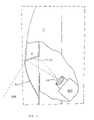
- FIG. 1is a top view of a vehicle equipped with the rear view monitoring system of the present invention, and includes a diagrammatic representation of viewing areas relative to the vehicle.
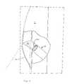
- FIG. 2is a magnified top view, partly in section, of the area enclosed by broken lines marked “FIG. 2 ” of FIG. 1 , showing schematic details of a video assembly employed in the present invention.
- FIG. 3is a side view taken in the direction of the arrows upon line 3 — 3 of FIG. 1 .
- FIG. 4is an enlarged fragmentary sectional view taken in the direction of the arrows upon line 4 — 4 of FIG. 1 .
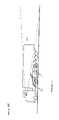
- FIG. 5is a side view of a large truck equipped with the rear view monitoring system of the present invention, and further showing the associated viewing areas.
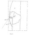
- FIG. 6is a top view of a vehicle equipped with a rear view mirror system of the prior art, and further shows associated viewing areas.
- FIG. 7is a side view of a truck equipped with a rear view mirror system of the prior art, and further shows the consequent viewing area.
- FIG. 8is a magnified top view, partly in section, of an area similar to that shown in FIG. 2 , showing details of a first alternative embodiment of the video assembly employed in the present invention.
- FIG. 9is a magnified top view, partly in section, of an area similar to that shown in FIG. 2 , showing details of a second alternative embodiment of the video assembly employed in the present invention.
- a passenger vehicle 1having front portion 2 terminating in bumper 33 , rear portion 3 , left side portion 4 and right side portion 5 .
- Said vehiclehaving a center axis of elongation 107 , further comprises a passenger compartment 30 bounded in part by said front and rear, left side and right side portions, and roof 26 .
- Upwardly directed pillars 27support said roof, and are located at four sites about the perimeter of said compartment in a rectangular array.
- a windshield 28generally encloses the front of the compartment, extending upwardly from a dashboard 29 to roof 26 .
- a first, left video assembly 6is installed within the left front fender 7 of the car, and a second, right video assembly 8 is installed within right front fender 9 .
- the contour of assemblies 6 and 8are styled to blend harmoniously with fenders 7 and 9 , respectively.
- Each video assemblyis comprised of an optical lens 10 capable of gathering light at a particular viewing angle to produce a focused image, and a camera body 105 which converts said image into an electronic signal amenable to alteration and transmission by electronic means.
- Image reversal meansare also associated with each video assembly.
- a mirror 20 or equivalent prism 62is disposed directly in front of the lens and thereby reflects a mirror image into the lens. In such embodiment, the mirror or prism is directed toward the rear of the vehicle.
- the camera bodyinstead of employing a mirror or prism, the camera body achieves reversal of the image by electronic means. Because said mirror-dependent first embodiment allows greater adaptability of placement in the vehicle, its use is emphasized in this disclosure.
- Left rear view mirror 20is positioned to reflect an image of rearwardly monitored area 103 at the left of the vehicle into associated video lens 10 .
- Right rear view mirror 21is similarly positioned to reflect an image of rearwardly monitored area 104 at the right of the vehicle into the lens component of right video assembly 8 .
- Mirrors 20 and 21are of substantially rectangular shape, and may be flat or convex, but are identical with respect to viewing angle and consequent magnification effect.
- Video assemblies 6 and 8may be miniaturized so that mirrors 20 and 21 are each reduced to about an inch or less in diameter, and are placed in close enough proximity to the associated lenses to enable the lens to function at its full viewing potential.
- miniaturizationallows mirrors 20 and 21 to be designed in a manner that will blend maximally with the external contour of the vehicle and be as inconspicuous as possible. It is intended that no component of the video assembly will protrude more than 2 inches away from the vehicle.
- Contoured, scratch-resistant, optically neutral, easily replaceable lens covers 24 and 25may be provided for improved styling and protective maintenance.
- Left video assembly 6continuously converts the captured image into electronic data. Said data is transmitted through suitable electrical circuitry to left monitor assembly 12 where it is continuously converted back into a visual picture which is displayed on monitor screen 13 . Since the image captured by left video lens 10 is actually a mirror image of the area to the left and rear of the vehicle as reflected by left rear view mirror 20 , the image produced on monitor screen 13 is also a mirror image.
- Right video assembly 8likewise continuously translates the image captured by its lens into electronic data which is electronically transmitted to right monitor assembly 14 . Said data is continuously converted back into a visual display picture on right monitor screen 15 . Since the image captured by the right video lens is a mirror image as reflected by right rear view mirror 21 , the visual picture displayed on right monitor screen 15 is also a mirror image.
- Third video assembly 16is installed in a location at the rear of the vehicle, preferably directly above center axis 107 . It houses a rearward facing central rear view mirror 22 for reflecting an image of monitored area 108 rearwardly of the vehicle into the lens of the video assembly. Said image is processed into an electronic signal which is transmitted to central monitor screen 19 and there converted into a corresponding easily viewed picture.
- Rear video assembly 16may be miniaturized to achieve the styling advantages already described, and may be provided with a lens cover as well. Alternatively, said third video assembly may be housed entirely within the vehicle.
- the lenses of the video assembliesare preferably designed to embrace viewing angles between 35 and 46 degrees so that they can cover large areas of surveillance while still producing images of adequate size.
- the rear view monitoring system of this inventionis amenable to adjustability of viewing angles and/or image magnification. Such adjustability can be met through proper selection of lenses. For example, a lens of 50 mm. focal length has a viewing angle of 46 degrees, and a lens of 75 mm. focal length has a viewing angle of about 35 degrees.
- the use of zoom lensescould provide adjustable viewing angles. Adjustment controls may be located on the dashboard within convenient reach of the driver. It is preferred, however that the three video assemblies provide the same degree of image magnification, and in this connection it should be noted that image magnification is determined by the viewing angle or focal length of the lens. In particular, shorter focal length lenses, with their attendant wide viewing angle produce smaller images.
- the monitoring system of this inventioncan provide a controlled amount of overlap between the view seen at the center screen and the views seen at the side screen.
- Such overlapprovides continuity of imagery as traffic flows from the field of view of one monitor to that of the other. It is preferred that such overlap be between 5 and 20 percent of the image area at both lateral extremities 116 of central monitor screen 19 .
- the video assemblies 6 and 8are positioned as far forward on the vehicle as practicable, such as in the illustrated locations far forward on the front fenders. By locating these side imaging units forwardly, a smaller viewing angle is needed to achieve satisfactory coverage of the “blind spots.” Proper forward positioning of the first and second, side imaging video assemblies enables them to cover desired areas 103 and 104 employing a viewing angle that matches the viewing of the third video assembly. Such matching will cause the pictures on the three screens to be of equal magnification without need for electronic adjustment.
- Such location of video assemblies 6 and 8is preferably at a site between 65% and 80% of the distance measured from windshield 28 toward bumper 33 .
- FIG. 1shows a typical rear view mirror arrangement of the prior art.
- the viewing angle provided by the mirror or video assemblyis shown at 42 degrees as bounded by the side of the vehicle and the broken straight diagonal line 112 .
- a lateral line of sight, shown as broken line 110is centered upon the head of the driver 111 .
- the distance 113shown bracketed, between the side of the vehicle and diagonal line 112 for each case, it is seen that such distance, which is essentially an effective field of view, is at least 50% greater by virtue of the forward placement of the video assemblies.
- Monitor screens 13 , 15 and 19are preferably equipped with means for controlling contrast, brightness and possibly size of the displayed images, with conveniently located control knobs.
- the left and right monitor screens 13 and 15are best located on the dashboard near the left and right roof-supporting pillars 27 so that they will be in the approximate area where the driver would ordinarily look as a matter of habit and experience to check the rear view.
- central monitor screen 19is best centered high behind windshield 28 where the inside rear view mirror is usually located, as shown in FIG. 4 .
- mirrors 20 and 21 when used on trucks, having a compartment or “cab” situated in a high position such as above the engine,would be similar to those for cars, i.e. on the front fenders.
- Thishas the advantage of visualizing low silhouette vehicles which are otherwise difficult to see with high mounted rear view mirrors, as previously described. This is illustrated by the high viewing area 117 achieved by prior truck side mirror systems, as shown in FIG. 7 . Such high viewing area fails to embrace vehicle 1 alongside the truck.
- Suitable locations for the rear video assembly 16 for cars and trucksare shown in FIGS. 1 and 3 , and in FIG. 5 , respectively.
- FIG. 8a video assembly 60 disposed in left front fender 7 , equipped with lens 100 directed rearwardly and to the left in order to capture a suitable view of area 103 to the left and rear of the vehicle.
- the image captured by lens 100is electronically processed into its mirror image and electronically transmitted to left monitor assembly 12 where it is displayed as the mirror image of the observed area.
- a similar video assemblyis disposed in the right front fender.
- FIG. 9Another embodiment of video assembly is shown in FIG. 9 where left video assembly 61 is disposed in the left front fender 7 of the vehicle.
- Reflecting prism 62is positioned to reflect a mirror image of area 103 to the left and rear of the vehicle. This image is captured by lens 101 of video assembly 61 and is processed into electronic signals that are transmitted to left monitor assembly 12 where it is displayed as a mirror image of the observed area.
- a similar video assemblyis disposed in the right front fender.
- the rear view video assemblies of this inventionserve more effectively than current rear view mirrors and may therefore be used in their place.
- the rear view monitoring system of this inventionprovides the driver with substantially complete imagery of significant areas to the side and rear of his vehicle.
- the provided imagesare of equal, non-distorted optical characteristics and can be modified with respect to brightness and contrast.
- the functionality of the systemis unaffected by deposits of fog, rain or snow on the vehicle's windows.
- the interior placement of components of the systemenhances the appearance and streamlining of the vehicle. Furthermore, the system does not require adjustment to accommodate drivers of different heights.
Landscapes
- Engineering & Computer Science (AREA)
- Multimedia (AREA)
- Mechanical Engineering (AREA)
- Signal Processing (AREA)
- Closed-Circuit Television Systems (AREA)
Abstract
Description
- a) first and second rear view side video assemblies installable on opposite sides of the front portion of said vehicle and positioned and configured to produce mirror images of rearward areas contiguous to the left and right sides of the vehicle, respectively,
- b) a third video assembly installable at the rear of said vehicle and configured to produce a mirror image of an area behind said vehicle, and
- c) monitor screens located within said compartment and separately interactive with each video assembly to provide visually observable pictures corresponding to said mirror images, the screens associated with said first and second video assemblies being positioned adjacent pillars on the same side of the compartment as the associated video assembly, and the screen associated with said third video assembly being centered high upon said front windshield.
Claims (12)
Priority Applications (1)
| Application Number | Priority Date | Filing Date | Title |
|---|---|---|---|
| US10/830,077US7057500B1 (en) | 2004-04-23 | 2004-04-23 | Rear view monitoring system for motor vehicles |
Applications Claiming Priority (1)
| Application Number | Priority Date | Filing Date | Title |
|---|---|---|---|
| US10/830,077US7057500B1 (en) | 2004-04-23 | 2004-04-23 | Rear view monitoring system for motor vehicles |
Publications (1)
| Publication Number | Publication Date |
|---|---|
| US7057500B1true US7057500B1 (en) | 2006-06-06 |
Family
ID=36568927
Family Applications (1)
| Application Number | Title | Priority Date | Filing Date |
|---|---|---|---|
| US10/830,077Expired - Fee RelatedUS7057500B1 (en) | 2004-04-23 | 2004-04-23 | Rear view monitoring system for motor vehicles |
Country Status (1)
| Country | Link |
|---|---|
| US (1) | US7057500B1 (en) |
Cited By (18)
| Publication number | Priority date | Publication date | Assignee | Title |
|---|---|---|---|---|
| US20070117083A1 (en)* | 2005-11-21 | 2007-05-24 | Winneg Douglas M | Systems, methods and apparatus for monitoring exams |
| US20070241536A1 (en)* | 2006-04-15 | 2007-10-18 | Wilkinson Reginald D | Viewing assembly and a method for coupling a trailer to a selectively movable assembly |
| US20080012938A1 (en)* | 2006-07-12 | 2008-01-17 | Aisin Aw Co., Ltd. | Driving support method and apparatus |
| US20090021609A1 (en)* | 2007-07-16 | 2009-01-22 | Trw Automotive U.S. Llc | Method and apparatus for distortion correction and image enhancing of a vehicle rear viewing system |
| US20090040300A1 (en)* | 2007-08-06 | 2009-02-12 | Two Loons Trading Company | Removably Mountable, Portable Vision System |
| US20090153665A1 (en)* | 2007-11-23 | 2009-06-18 | Visiocorp Patents S.A.R.I. | Lane change control system |
| DE102009012615A1 (en)* | 2009-03-11 | 2010-09-16 | GM Global Technology Operations, Inc., Detroit | Vehicle outdoor aerial unit for assembly on external side of vehicle, has housing, in which antenna is arranged, and camera is provided in housing |
| US20110102583A1 (en)* | 2009-10-30 | 2011-05-05 | Kim Kinzalow | Rear view camera system and calibration method |
| EP2540571A4 (en)* | 2010-02-24 | 2013-08-14 | Sung-Ho Cho | Left/right rearview device for a vehicle |
| WO2016058211A1 (en)* | 2014-10-22 | 2016-04-21 | 韩性峰 | Vehicle rearview projector |
| JP2016172526A (en)* | 2015-03-18 | 2016-09-29 | マツダ株式会社 | Vehicle display device |
| GB2544122A (en)* | 2015-11-06 | 2017-05-10 | Bombardier Transp Gmbh | Rail vehicle provided with an internally mounted video camera with external field of vision |
| US20170214130A1 (en)* | 2016-01-21 | 2017-07-27 | Connaught Electronics Ltd. | Antenna module for a motor vehicle, driver assistance system as well as motor vehicle |
| WO2017125477A1 (en)* | 2016-01-21 | 2017-07-27 | Connaught Electronics Ltd. | Antenna module for a motor vehicle, driver assistance system as well as motor vehicle |
| WO2018100870A1 (en)* | 2016-12-01 | 2018-06-07 | 株式会社東海理化電機製作所 | Image display system and image display method |
| DE102017100602A1 (en) | 2017-01-13 | 2018-07-19 | Connaught Electronics Ltd. | Electronic side mirror for a motor vehicle with a camera arranged in a housing of the electronic side mirror, camera system and motor vehicle |
| US11113824B2 (en)* | 2019-04-30 | 2021-09-07 | Aptiv Technologies Limited | Heading angle estimation for object tracking |
| USD938889S1 (en)* | 2020-01-06 | 2021-12-21 | Gentex Corporation | Vehicle door with display |
Citations (5)
| Publication number | Priority date | Publication date | Assignee | Title |
|---|---|---|---|---|
| US4277804A (en) | 1978-11-01 | 1981-07-07 | Elburn Robison | System for viewing the area rearwardly of a vehicle |
| US5949331A (en)* | 1993-02-26 | 1999-09-07 | Donnelly Corporation | Display enhancements for vehicle vision system |
| US6424273B1 (en) | 2001-03-30 | 2002-07-23 | Koninklijke Philips Electronics N.V. | System to aid a driver to determine whether to change lanes |
| US6509832B1 (en)* | 1998-09-15 | 2003-01-21 | Gentex Corporation | Systems and components for enhancing rear vision from a vehicle |
| US6891563B2 (en)* | 1996-05-22 | 2005-05-10 | Donnelly Corporation | Vehicular vision system |
- 2004
- 2004-04-23USUS10/830,077patent/US7057500B1/ennot_activeExpired - Fee Related
Patent Citations (7)
| Publication number | Priority date | Publication date | Assignee | Title |
|---|---|---|---|---|
| US4277804A (en) | 1978-11-01 | 1981-07-07 | Elburn Robison | System for viewing the area rearwardly of a vehicle |
| US5949331A (en)* | 1993-02-26 | 1999-09-07 | Donnelly Corporation | Display enhancements for vehicle vision system |
| US6222447B1 (en)* | 1993-02-26 | 2001-04-24 | Donnelly Corporation | Rearview vision system with indicia of backup travel |
| US6891563B2 (en)* | 1996-05-22 | 2005-05-10 | Donnelly Corporation | Vehicular vision system |
| US6509832B1 (en)* | 1998-09-15 | 2003-01-21 | Gentex Corporation | Systems and components for enhancing rear vision from a vehicle |
| US6672745B1 (en)* | 1998-09-15 | 2004-01-06 | Gentex Corporation | Systems and components for enhancing rear vision from a vehicle |
| US6424273B1 (en) | 2001-03-30 | 2002-07-23 | Koninklijke Philips Electronics N.V. | System to aid a driver to determine whether to change lanes |
Cited By (29)
| Publication number | Priority date | Publication date | Assignee | Title |
|---|---|---|---|---|
| US20070117082A1 (en)* | 2005-11-21 | 2007-05-24 | Winneg Douglas M | Systems, methods and apparatus for monitoring exams |
| US20070117083A1 (en)* | 2005-11-21 | 2007-05-24 | Winneg Douglas M | Systems, methods and apparatus for monitoring exams |
| US20070241536A1 (en)* | 2006-04-15 | 2007-10-18 | Wilkinson Reginald D | Viewing assembly and a method for coupling a trailer to a selectively movable assembly |
| US7621555B2 (en) | 2006-04-15 | 2009-11-24 | Wilkinson Reginald D | Viewing assembly and a method for coupling a trailer to a selectively movable assembly |
| US8094190B2 (en)* | 2006-07-12 | 2012-01-10 | Aisin Aw Co., Ltd. | Driving support method and apparatus |
| US20080012938A1 (en)* | 2006-07-12 | 2008-01-17 | Aisin Aw Co., Ltd. | Driving support method and apparatus |
| US20090021609A1 (en)* | 2007-07-16 | 2009-01-22 | Trw Automotive U.S. Llc | Method and apparatus for distortion correction and image enhancing of a vehicle rear viewing system |
| US8233045B2 (en) | 2007-07-16 | 2012-07-31 | Trw Automotive U.S. Llc | Method and apparatus for distortion correction and image enhancing of a vehicle rear viewing system |
| US20090040300A1 (en)* | 2007-08-06 | 2009-02-12 | Two Loons Trading Company | Removably Mountable, Portable Vision System |
| US20090153665A1 (en)* | 2007-11-23 | 2009-06-18 | Visiocorp Patents S.A.R.I. | Lane change control system |
| US8537221B2 (en)* | 2007-11-23 | 2013-09-17 | SMR Patents S.à.r.l. | Lane change control system |
| DE102009012615A1 (en)* | 2009-03-11 | 2010-09-16 | GM Global Technology Operations, Inc., Detroit | Vehicle outdoor aerial unit for assembly on external side of vehicle, has housing, in which antenna is arranged, and camera is provided in housing |
| US20110102583A1 (en)* | 2009-10-30 | 2011-05-05 | Kim Kinzalow | Rear view camera system and calibration method |
| EP2540571A4 (en)* | 2010-02-24 | 2013-08-14 | Sung-Ho Cho | Left/right rearview device for a vehicle |
| WO2016058211A1 (en)* | 2014-10-22 | 2016-04-21 | 韩性峰 | Vehicle rearview projector |
| JP2016172526A (en)* | 2015-03-18 | 2016-09-29 | マツダ株式会社 | Vehicle display device |
| GB2544122A (en)* | 2015-11-06 | 2017-05-10 | Bombardier Transp Gmbh | Rail vehicle provided with an internally mounted video camera with external field of vision |
| WO2017076995A1 (en)* | 2015-11-06 | 2017-05-11 | Bombardier Transportation Gmbh | Rail vehicle provided with an internally mounted video camera with external field of vision |
| US10707567B2 (en)* | 2016-01-21 | 2020-07-07 | Connaught Electronics Ltd. | Antenna module for a motor vehicle, driver assistance system as well as motor vehicle |
| WO2017125477A1 (en)* | 2016-01-21 | 2017-07-27 | Connaught Electronics Ltd. | Antenna module for a motor vehicle, driver assistance system as well as motor vehicle |
| WO2017125552A1 (en)* | 2016-01-21 | 2017-07-27 | Connaught Electronics Ltd. | Antenna module for a motor vehicle, driver assistance system as well as motor vehicle |
| US20170214130A1 (en)* | 2016-01-21 | 2017-07-27 | Connaught Electronics Ltd. | Antenna module for a motor vehicle, driver assistance system as well as motor vehicle |
| WO2018100870A1 (en)* | 2016-12-01 | 2018-06-07 | 株式会社東海理化電機製作所 | Image display system and image display method |
| JP2018091969A (en)* | 2016-12-01 | 2018-06-14 | 株式会社東海理化電機製作所 | Image display system and image display method |
| DE102017100602A1 (en) | 2017-01-13 | 2018-07-19 | Connaught Electronics Ltd. | Electronic side mirror for a motor vehicle with a camera arranged in a housing of the electronic side mirror, camera system and motor vehicle |
| US11113824B2 (en)* | 2019-04-30 | 2021-09-07 | Aptiv Technologies Limited | Heading angle estimation for object tracking |
| US11615538B2 (en) | 2019-04-30 | 2023-03-28 | Aptiv Technologies Limited | Heading angle estimation for object tracking |
| USD938889S1 (en)* | 2020-01-06 | 2021-12-21 | Gentex Corporation | Vehicle door with display |
| USD1017515S1 (en) | 2020-01-06 | 2024-03-12 | Gentex Corporation | Display for a vehicle door |
Similar Documents
| Publication | Publication Date | Title |
|---|---|---|
| US7057500B1 (en) | Rear view monitoring system for motor vehicles | |
| US11679719B2 (en) | Vehicular vision system with console video display and mirror video display for exterior viewing cameras | |
| US6447128B1 (en) | Rearview mirror assembly for a vehicle with monitor | |
| US5027200A (en) | Enhanced viewing at side and rear of motor vehicles | |
| US5289321A (en) | Consolidated rear view camera and display system for motor vehicle | |
| US6384741B1 (en) | Apparatus and method for providing high mounted view of traffic | |
| US6151065A (en) | Concealed integrated vehicular camera safety system | |
| EP0711681B1 (en) | Back-vision system for vehicles | |
| US20040036768A1 (en) | System and method for electronically viewing behind a vehicle | |
| WO1996021581A1 (en) | Backward ans site-backward watching system for automobile | |
| US20020113873A1 (en) | Rear vision system for large vehicles | |
| US20080068455A1 (en) | Rear facing viewing system for large vehicles | |
| US20130155236A1 (en) | Camera-mirror system for motor vehicle | |
| KR101552444B1 (en) | Visual system | |
| JP2001187547A (en) | Image acquisition and indication assembly for vehicle | |
| EP1527606B1 (en) | Viewing system | |
| JP2005534246A5 (en) | ||
| CN111655541B (en) | Driver assistance system for industrial vehicles | |
| GB2397189A (en) | Forward looking road monitoring system for vehicles | |
| EP1456058A1 (en) | Vehicle imaging system | |
| US20020126206A1 (en) | Electronic side--view mirrors for motor vehicles using exterior cameras wired to interior monitor | |
| US6850827B1 (en) | Rearward viewing system for use with vehicles | |
| Wierwille et al. | Development of a performance specification for camera/video imaging systems on heavy vehicles | |
| CN221642380U (en) | Novel CMS system and vehicle | |
| Wierwille et al. | Development of a Performance Specification for Camera/Video Imaging Systems on Heavy Vehicles-Final Report: Specifications |
Legal Events
| Date | Code | Title | Description |
|---|---|---|---|
| FPAY | Fee payment | Year of fee payment:4 | |
| FEPP | Fee payment procedure | Free format text:PETITION RELATED TO MAINTENANCE FEES DISMISSED (ORIGINAL EVENT CODE: PMFS); ENTITY STATUS OF PATENT OWNER: MICROENTITY Free format text:PAT HOLDER CLAIMS SMALL ENTITY STATUS, ENTITY STATUS SET TO SMALL (ORIGINAL EVENT CODE: LTOS); ENTITY STATUS OF PATENT OWNER: MICROENTITY Free format text:PETITION RELATED TO MAINTENANCE FEES FILED (ORIGINAL EVENT CODE: PMFP); ENTITY STATUS OF PATENT OWNER: MICROENTITY | |
| FEPP | Fee payment procedure | Free format text:PETITION RELATED TO MAINTENANCE FEES GRANTED (ORIGINAL EVENT CODE: PMFG); ENTITY STATUS OF PATENT OWNER: MICROENTITY | |
| FEPP | Fee payment procedure | Free format text:PETITION RELATED TO MAINTENANCE FEES FILED (ORIGINAL EVENT CODE: PMFP); ENTITY STATUS OF PATENT OWNER: MICROENTITY | |
| REMI | Maintenance fee reminder mailed | ||
| LAPS | Lapse for failure to pay maintenance fees | ||
| REIN | Reinstatement after maintenance fee payment confirmed | ||
| FPAY | Fee payment | Year of fee payment:8 | |
| FP | Lapsed due to failure to pay maintenance fee | Effective date:20140606 | |
| PRDP | Patent reinstated due to the acceptance of a late maintenance fee | Effective date:20141113 | |
| AS | Assignment | Owner name:BAYSHORE PATENTS LLC, FLORIDA Free format text:ASSIGNMENT OF ASSIGNORS INTEREST;ASSIGNOR:BELLOSO, GREGORIO;REEL/FRAME:042424/0413 Effective date:20170425 | |
| FEPP | Fee payment procedure | Free format text:MAINTENANCE FEE REMINDER MAILED (ORIGINAL EVENT CODE: REM.) | |
| AS | Assignment | Owner name:TOYOTA MOTOR CORPORATION, JAPAN Free format text:ASSIGNMENT OF ASSIGNORS INTEREST;ASSIGNOR:BAYSHORE PATENTS LLC;REEL/FRAME:046226/0298 Effective date:20180606 | |
| LAPS | Lapse for failure to pay maintenance fees | Free format text:PATENT EXPIRED FOR FAILURE TO PAY MAINTENANCE FEES (ORIGINAL EVENT CODE: EXP.) | |
| STCH | Information on status: patent discontinuation | Free format text:PATENT EXPIRED DUE TO NONPAYMENT OF MAINTENANCE FEES UNDER 37 CFR 1.362 | |
| FP | Lapsed due to failure to pay maintenance fee | Effective date:20180606 |