US7057383B2 - Method for decoupling interference due to bleedover in metallic pipe and cable locators - Google Patents
Method for decoupling interference due to bleedover in metallic pipe and cable locatorsDownload PDFInfo
- Publication number
- US7057383B2 US7057383B2US10/842,239US84223904AUS7057383B2US 7057383 B2US7057383 B2US 7057383B2US 84223904 AUS84223904 AUS 84223904AUS 7057383 B2US7057383 B2US 7057383B2
- Authority
- US
- United States
- Prior art keywords
- signal
- coupled
- phase
- frequency
- locator
- Prior art date
- Legal status (The legal status is an assumption and is not a legal conclusion. Google has not performed a legal analysis and makes no representation as to the accuracy of the status listed.)
- Expired - Lifetime, expires
Links
Images


Classifications
- G—PHYSICS
- G01—MEASURING; TESTING
- G01V—GEOPHYSICS; GRAVITATIONAL MEASUREMENTS; DETECTING MASSES OR OBJECTS; TAGS
- G01V3/00—Electric or magnetic prospecting or detecting; Measuring magnetic field characteristics of the earth, e.g. declination, deviation
- G01V3/08—Electric or magnetic prospecting or detecting; Measuring magnetic field characteristics of the earth, e.g. declination, deviation operating with magnetic or electric fields produced or modified by objects or geological structures or by detecting devices
- G01V3/088—Electric or magnetic prospecting or detecting; Measuring magnetic field characteristics of the earth, e.g. declination, deviation operating with magnetic or electric fields produced or modified by objects or geological structures or by detecting devices operating with electric fields
Definitions
- the present inventionrelates to detection of electromagnetic signals from targeted hidden conductors and, in particular, to the decoupling of interference signals in detected signals from the targeted hidden conductors that result from bleedover of the transmitted signal to adjacent non-targeted conductors.
- Line locator systemstypically include a mobile receiver and a transmitter.
- the transmitteris coupled to a target conductor, either by direct electrical connection or through induction, to provide a current signal on the target conductor.
- the receiverdetects and processes signals resulting from the electromagnetic field generated at the target conductor as a result of the current signal, which can be a continuous wave sinusoidal signal provided to the target conductor by the transmitter.
- the transmitteris often physically separated from the receiver, with a typical separation distance of several meters or in some cases up to many kilometers.
- the transmittercouples the current signal, whose frequency can be user chosen from a selectable set of frequencies, to the target conductor.
- the frequency of the current signal applied to the target conductorcan be referred to as the active locate frequency.
- the target conductorthen generates an electromagnetic field at the active locate frequency in response to the current signal.
- the typical range of active locate frequenciescan be from several Hertz (for location of the target conductor over separation distances between the transmitter and receiver of many kilometers) to 100 kHz or more.
- Significant radio frequency interference on the electromagentic field detected by the receivercan be present in the environment over this range. Therefore, receivers of line location systems have often included highly tuned filters to preclude interference from outside sources from affecting the measurement of signals at the desired active locate frequency from the target conductor. These filters can be tuned to receive signals resulting from electromagnetic fields at each of the selectable active locate frequencies and reject signals resulting from electromagnetic fields at frequencies other than the active locate frequencies.
- the signal strength parameter determined from detection of the electromagnetic fieldprovides basis for derived quantities of the current signal (i.e., the line current in the targeted conductor), position of the line locator receiver relative to the center of the conductor, depth of the conductor from the line locator receiver, and can also be used as the input to a peak or null indicator (depending on the orientation of the magnetic field to which that the detector is sensitive). All line location systems measure signal strength on one or more measurement channels.
- a receiver for a line locatorincludes a first digital phase-locked loop coupled to receive an input signal and lock to a carrier frequency of the input signal; a second digital phase-locked loop coupled to receive an FM signal from the first digital phase-locked loop and lock to a modulation frequency of the input signal; and a quadrature demodulator coupled to receive the input signal and a frequency signal from the second digital phase-locked loop and provide an in-phase signal.
- a line locator systemincludes a transmitter coupled to provide a current signal to a target conductor, the current signal including at least one signal at a carrier frequency, the signal being modulated at a modulation frequency; and a locator.
- the locatorincludes a detector system that provides at least one signal related to an electromagnetic field present at the locator; at least one receiver coupled to receive the at least one signal, each of the at least one receiver including a first digital phase-locked loop that locks to the carrier frequency of one of the at least one signal, a second digital phase-locked loop coupled to receive an FM signal from the first digital phase-locked loop and lock to the modulation frequency of the one of the at least one signal; and a quadrature demodulator coupled to receive the one of the at least one signal and a frequency signal from the second digital phase-locked loop and provide an in-phase signal; and a display coupled to receive the in-phase signal and provide information to a user.
- a method of detecting signals associated with a target conductor while rejecting signals associated with bleedover to neighboring conductorsincludes providing an input signal in response to an electromagnetic field; locking to a carrier frequency of the input signal and providing an FM signal; locking to a modulation frequency in the FM signal signal and providing a frequency signal; and mixing the frequency signal with the input signal to provide an in-phase signal.
- a method of determining a depth of a target conductorincludes providing a current signal on the target conductor, the current signal including a signal at a carrier frequency, the signal being modulated at a modulation frequency; determining a target line signal strength at a plurality of positions, the plurality of positions disposed along a line substantially perpendicular to a line of travel of the target conductor; and determining the depth from the target line signal strength at the plurality of positions.
- the target line signal strength at each of the plurality of positionscan be determined by providing an input signal in response to an electromagnetic field at the position, locking to a carrier frequency of the input signal and providing an FM signal signal, locking to a modulation frequency in the FM signal and providing a frequency signal, mixing the frequency signal with the input signal to provide an in-phase signal, and determining the target line signal strength from the in-phase signal.
- FIG. 1Aillustrates utilization of a line locator system.
- FIG. 1Billustrates an example of electrical circuits that can be created during line location in a particular conductor topology.
- FIG. 2shows a simplified equivalent circuit to those shown in FIG. 1B .
- FIGS. 3A and 3Bshow schematically the equivalent electrical circuit of the situation shown in FIG. 2 and illustrates the current signals.
- FIG. 4illustrates in a block diagram of a receiver according to the present invention.
- FIG. 5illustrates a digital phase locked loop that can be utilized in embodiments of a receiver according to the present invention.
- FIG. 6illustrates another embodiment of receiver according to the present invention.
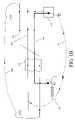
- FIG. 7is a cross section of an underground locate scenario with only one pipe or cable (directed into and out of the paper).
- FIGS. 8A and 8Billustrate determination of line location and depth with two buried conductors separated by an unknown distance.
- FIG. 1Aillustrates a line location environment with a line locator.
- the line locatorincludes locator 110 and transmitter 101 .
- Locator 110can include an embodiment of receiver according to the present invention or may be a conventional locator.
- An example of a mostly digital implementation of a receiver 110is described in U.S. application Ser. No. 10/622,376, “Method and Apparatus for Digital Detection of Electromagnetic Signal Strength and Signal Direction in Metallic Pipes and Cables,” by James W. Waite and Johan D. Overby (the '376 application), which is assigned to the same assignee as is the present invention and herein incorporated by reference in its entirety.
- Locator 110is operated by operator 116 in order to locate target conductor 104 .
- Target conductor 104is directly coupled to transmitter 101 .
- transmitter 101couples a current signal onto conductor 104 .
- the current signalhas a frequency at the active locate frequency, which can be one of a set of standardized frequencies.
- target conductor 104can be below ground.
- Transmitter 101can be coupled to line 104 directly at an above ground junction box or by digging to line 104 in a known location.
- Transmitter 101can also be electrically coupled to line 104 inductively.
- Receiver 110includes detectors 112 and a display 114 .
- Detectors 112can be any detectors for determining an electromagnetic field.
- detectors 112can include coils which provide electrical signals in the presence of time varying magnetic fields. Electrical signals can be processed in receiver 110 and the results of the processing can be communicated to operator 116 on display 114 .
- Detectors 112can detect magnetic field 118 generated by the current signal in target conductor 104 . However, a current of the same frequency can be coupled into neighboring line 126 by resistive coupling, capacitive coupling, or inductive coupling. Neighboring line 126 , then, can generate magnetic field 120 . The signal provided to locator 110 by detectors 112 , then, will reflect the contributions from both magnetic field 118 from target conductor 104 and magnetic field 120 from neighboring conductor 126 . Calculations of the depth of target line 104 or the current in target line 104 , then, may be inaccurate.
- resistive couplingoccurs between adjacent lines. If resistive coupling occurs, the induced voltage signal in the adjacent line is reversed (180° out of phase) from the current signal present in the target conductor. This is because the current that has propagated to the adjacent line is seeking an easier (i.e., lower impedance) return path to the same ground stake at the transmitter of the line locating system.
- the outgoing signal from transmitter 101is taken as the positive direction, and the incoming signal to transmitter 101 is taken as the negative direction.
- Inductive and capacitive bleedovercan occur in long locates (i.e., where receiver 110 is well separated from transmitter 101 ) where target conductor 104 is of good quality and the resistance between ground and the cable sheath of target conductor 104 is high or, alternatively, where the active locate frequency is high (lowering the impedance threshold wherein capacitive coupling becomes a problem).
- capacitive or inductive bleedoverthe signal on the neighboring conductor (e.g., conductor 126 ) undergoes a phase shift that corresponds to the transfer function of the coupling. In situations where the coupling is predominantly inductive or capacitive, the signal is 90° out-of-phase from the current signal that is transmitted by transmitter 101 .
- the bleedover signal(the signal generated from detection of the electromagnetic field from the neighboring conductor) is significantly stronger than the signal generated in receiver 110 by detection of the electromagnetic field from target conductor 104 and completely dominates the measured field strength detected at receiver 110 .
- a particularly problematic measurement situationoccurs when the neighboring cable, for example conductor 126 in FIG. 1A , which carries a bleedover signal, is shallower than the target conductor.
- the combined signal at the receiver(e.g., the signal resulting from detection of both magnetic field 118 and magnetic field 120 at receiver 110 ) has the exact same frequency, the active locate frequency, as that of the current signal applied to target conductor 104 by transmitter 101 (it is assumed that the system is Linear Time Invariant (LTI), so the only phase changes observed are due to the bleedover coupling itself).
- LTILinear Time Invariant
- the electromagnetic field resulting from the bleedover signal in the shallower neighboring conductorcan be stronger than the electromagnetic field generated by target conductor 104 , in which case the measured signal at the receiver will tend toward a 90° phase shift from that imparted to targeted conductor 104 by transmitter 101 .
- transmitter 101usually includes a free running oscillator driver.
- the field strength measured by locator 110includes the effects of the inphase signals from detection of the electromagnetic field from targeted conductor 104 and the electromagnetic fields from the ground return, which are 180° out-of-phase, due to resistive bleedover, as well as the quadrature signals due to detection of electromagnetic fields from inductively or capacitively coupled lines.
- the net magnitude of these signalscan result in a non-concentric magnetic field, an effect which is commonly referred to as field distortion.
- the '342 applicationrefers to a numerical approach to compare signal strength measurements from three or more coils to those that would result from an undistorted field.
- Other approaches toward dealing with field distortionis to make use of position measurement methods to map the magnetic field over the surface of the ground and detect non-concentric fields, a good indication of distortion.
- a line locator that includes an inertial position-tracking deviceis described in U.S. patent application Ser. No. 10/407,705 “Buried Line Locator with Integral Position Sensing”, by Gordon Pacey and assigned to Metrotech Corporation, which is herein incorporated by reference in its entirety.
- the measured field strength parameter, detected from the electromagnetic field at locator 110can be a combination of both the radiating targeted conductor as well as other neighboring coupled conductors.
- the degree of distortion presentis a primary factor in the overall quality of the target conductor locate.
- U.S. Pat. No. 6,411,073 and the '376 applicationteach that the signal direction parameter is useful to discriminate the targeted conductor from ground return currents present in parallel-coupled conductors.
- the direction of the signal at the receiveris derived from the Signal Select modulation to the signal imparted at the transmitter thus a common phase reference is available at the receiver.
- a locator 110that includes a receiver that separates the signal resulting from the detection of the electromagnetic field at receiver 110 into an inphase and a quadrature signal.
- the signals resulting from the current signal applied to the targeted conductor and from resistively coupled bleedoverare separated from signals resulting from inductive or capacitive bleedover.
- Embodiments of the present inventionextend the receiver processing associated with Signal Select (as described in the '376 application) demodulation to allow a distinct separation of resistively coupled signals (from the target conductor and ground return path signals) from undesirable (distortion causing) signals caused by inductive or capacitive coupling.
- the most frequent form of couplingis resistive, of which ground return currents in conductors lying parallel to the target line over the entire length of the locate are the most typical. This is a common problem in city scenarios.
- the current flowing through a cable returning via other cables (or ground)generates a magnetic field that is sensed with the opposite polarity by a coil antenna of receiver 110 .
- a coil antenna of receiver 110On long cables, e.g., about 50 miles and longer, it is less likely that a non-targeted conductor lies parallel over the entire course and hence its facility as an easy (i.e., low impedance) ground return path is limited.
- Capacitive couplingthe third possibility, can play a role in dry and low ground-conductivity areas. If the coupling on the majority of the cable run is inductive, then there will be a phase difference of close to 90°, as it is loose coupling via mutual induction. For capacitive coupling, the phase in the coupled circuit will be ⁇ 90°.
- the extracted signal phasehas not been used as a measure of the coupling type because a solid phase reference with respect to the transmitter phase has not been achieved.
- the '376 applicationnotes the development of a nested (dual) digital phase locked loop (DPLL) so that the Signal Select phase reference could be accurately recovered at the receiver.
- DPLLdigital phase locked loop
- the quadrature demodulated inphase signalincludes all resistively coupled (0° and 180°) signals and the demodulated quadrature signal is representative of the net inductive and capacitive coupling (+/ ⁇ 90°).
- the sign of the inphase signalis taken as the signal direction, representing the net direction of the resistively coupled signal, as is described in the '376 application.
- the processing at locator 110 of the Signal Select modulated locate signalcan be further enhanced by averaging and/or low-pass filtering, allowing stable estimates of target line field strength (cleaned of substantially all contribution due to inductively or capacitively coupled lines), total field strength (including that due to all coupled lines), and signal direction.
- the field strength valuescan be presented to user 116 at display 114 in a plot as a function of lateral position x over the targeted line, where x is the coordinate perpendicular to the cable.
- xis the coordinate perpendicular to the cable.
- the areas with large differences between the total field strength and the target conductor field strengthindicate the influence of a coupled line or lines.
- the target line field strengthbeing effectively cleaned of the influence of coupled lines, can be used to accurately triangulate or vector the coordinates of the underground conductor (both x position and depth).
- Some embodiments of the inventionfacilitate the use of non-linear optimization methods to simultaneously estimate the depth, position, and current flowing in targeted conductor 104 from the target line field strength. These estimates are more reliable in the presence of magnetic field distortion due to inductive or capacitive coupling because the target line field strength more closely conforms to the physical model of a concentric field around the targeted conductor 104 .
- two or more active Signal Select modulated frequenciescan be placed on target conductor 104 by transmitter 101 .
- the impedancedrops with increasing frequency, thus the difference between the total field strength and target field strength will be larger at the higher frequency.
- Some embodiments of the invention described hereincan utilize an efficient transmitter algorithm for generating multiple simultaneous Signal Select modulated frequencies on the targeted conductor.
- the receiver signal processingis expanded to implement multiple parallel Signal Select demodulation algorithms.
- FIG. 1Bis a depiction of a line locate scenario that involves a forward current from transmitter 101 to splice box, a reverse ground return current from the splice box back to the transmitter ground stake, and an induced current on neighboring line 106 .
- the conductor topology illustrated in FIG. 1Bshows a target conductor 104 and a neighboring conductor 106 .
- FIG. 1Balso illustrates a direct connection transmitter 101 electronically coupled to target conductor 104 .
- Line location using direct-connect transmitter 101utilizes a galvanic connection to the targeted conductor 104 (also referred to as the targeted line) such as is illustrated in FIG. 1B .
- the targeted conductor 104also referred to as the targeted line
- a galvanic connection to the targeted conductor 104such as is illustrated in FIG. 1B .
- a splice or junction box 102at the terminus of the line so that the far end of targeted conductor 104 (i.e., the end opposite transmitter 101 ) can be grounded to earth 107 .
- effective line tracingcan be achieved by grounding the metal sheath around the copper or fiber optic cable at the far end, so that a closed loop AC circuit is created as shown by the combination of paths 104 and 107 .
- Transmitter 101generates a current signal in target line 101 .
- the current signalincludes one or more modulated signals on a carrier signal.
- the current signal generated by transmitter 101can include signals at more than one carrier frequency in order that the influences associated with coupled neighboring conductors, which can be frequency dependent, can be more clearly distinguished.
- line 105can be electrically coupled to target conductor 104 .
- conductor 105is resistively coupled to target conductor 104 , i.e. the current moving through target conductor 104 uses line 103 as a lower impedance ground return path to transmitter 101 .
- Another current that is also a result of the signal generated by transmitter 101is flowing in conductor 106 .
- This currentis coupled into conductor 106 by virtue of inductive or capacitive coupling from target line 104 to conductor 106 .
- a separate current loopis set up through a loosely coupled ground 108 , so that the sense of the signal in coupled conductor 105 is still positive, i.e., in the same direction as the target conductor.
- a line locator measuring the signal strength in region 103thus sees a combination of signals due to the magnetic fields emanating from conductors 104 , 105 , and 106 .
- the sum of these signalsis a distorted field, since it no longer is concentric around the axis of targeted line 104 , as it would be if only targeted line 104 were carrying a current signal at the locate frequency.
- Some locatorshave been able to discriminate the reverse direction signal 105 from the forward signal on the targeted line 104 .
- Embodiments of the present inventioncan also explicitly identify the coupled signal present on conductor 106 .
- FIG. 2shows a simplified equivalent circuit to that shown in FIG. 1B .
- FIG. 2illustrates how mutual induction generates an AC current in coupled line 106 .
- the ground pathsare loosely coupled as well.
- FIG. 2is a simplified schematic of the situation, showing only the coupled conductor 106 carrying current I i and the target conductor 104 carrying current I g (for the galvanic, or directly coupled current).
- Transmitter 101is represented in this schematic as a signal generator.
- FIG. 3Ais a further reduction of the problem to an equivalent electrical schematic, with the loops 104 and 105 coupled together through mutual inductance 301 . It is well know that in the case of inductive coupling, the induced current I i lags the current in the primary loop I g by 90°, as is shown graphically in FIG. 3B .
- the current signal applied to target conductor 104 ( FIG. 1 ) by transmitter 101includes a carrier frequency, which is the active line locate frequency discussed above. Further, a FM modulation frequency can be imposed on the current signal. In some embodiments, the FM modulation frequency is an integer multiple of the carrier frequency.
- FIG. 4illustrates a block diagram of a receiver 410 according to the present invention.
- receiver 410is included in locator 110 .
- Receiver 410includes a detector 409 that detects the strength of an electromagnetic field and provides one or more input signals 401 .
- detector 409can include magnetic field detectors as well as filters and digitizers.
- locator 410can include multiple individual receivers 410 with detectors 409 oriented to detect magnetic fields of the electromagnetic field that are directed in particular directions.
- Receiver 410locks first onto the carrier frequency, i.e.
- the active locate frequencyin a digital phase-locked loop DPLL 402 and then onto the FM modulation frequency in DPLL 404 to provide a signal (the target line strength) that is not substantially influenced by inductive or capacitive bleedover to neighboring conductors.
- receiver 410processing first demodulates the Signal Select FM signal from the carrier signal, and then subsequently demodulates the original input signal by the detected reference phase.
- Input signal 401is first received in carrier DPLL 402 .
- the output signal from DPLL 402is coupled into FM Demodulation DPLL 404 . Therefore, DPLLs 402 and 404 lock first to the carrier frequency, and next to the FM modulation frequency, which is an error term resulting from operation of the DPLL 402 .
- a downsampler 403can be provided between DPLL 402 and DPLL 404 to improve processing efficiency because the FM modulation frequency can be a fraction of the carrier frequency.
- An output signal from DPLL 404is coupled into quadrature demodulator 406 , where it is utilized to demodulate input signal 401 .
- the resulting output signals from quadrature demodulator 406include an in-phase signal 408 that is the target line signal strength and a quadrature signal 407 that is the inductive or capacitive bleedover line signal strength.
- a quadrature upsampler 405can be included so that the sampling rate of in-phase signal 408 and quadrature signal 407 is adjusted.
- Signals generated in receiver 410can be further processed for display to user 116 and display 114 .
- FIG. 5illustrates an embodiment of carrier DPLL 402 according to the present invention.
- Carrier DPLL 402includes a mixer 501 that mixes signal input 401 with a periodic function generated by numerically controlled oscillator (NCO) 503 .
- a phase error signal 504is created by inverse tangent function 502 that receives a complex output signal from mixer 501 .
- a simple divide of the imaginary term by the real term of the input signalcan also form a simple estimate of the phase error, since the inverse tangent function 502 is approximately linear about zero.
- the phase error signal 504 from inverse tangent function 502is input to NCO 503 that adjusts the phase and frequency of the periodic function output to mixer 501 and can also output values for the phase and frequency.
- NCO 503can use second order loop equations to control the feedback to mixer 501 , allowing DPLL 402 to gradually converge to a lock condition.
- signal 505represents the difference between the signal input 401 and the average carrier at frequency F c , and is taken as a representation of the FM signal and is forwarded to FM DPLL 404 .
- FIG. 6illustrates another embodiment of receiver 410 according to the present invention.
- input signal 401is input to quadrature demodulator 406 and carrier DPLL 402 .
- carrier DPLL 402includes mixer 501 , arctangent function 502 , and NCO 503 .
- the FM signal from carrier DPLL 402is input to FM DPLL 404 .
- FM DPLL 404includes a mixer 611 , an arctangent function block 612 , and a numeric controlled oscillator 613 . As shown in FIG.
- mixer 611receives the FM signal from DPLL 402 and mixes an FM modulated signal output from numerically controlled oscillator 613 .
- Numerically controlled oscillator (NCO) 613adjusts the frequency and phase of the periodic function mixed in mixer 611 according to the FM phase error signal generated by arctangent function 612 .
- NCO 613can use second order loop equations to control the feedback to mixer 611 , allowing DPLL 404 to converge to a locked condition.
- the periodic feedback function input to mixer 611 in DPLL 404is also input to quadrature demodulator 406 .
- the magnitude 601 of the complex FM signal output from DPLL 402can be input to filter 602 to provide a total signal strength signal 603 .
- Total signal strength signal 603includes contributions from target conductor 104 , resistively coupled neighboring conductors such as conductor 105 shown in FIG. 1B , and inductively coupled neighboring conductors such as conductor 106 shown in FIG. 1B .
- quadrature demodulatorincludes a mixer 614 , an in-phase filter 616 , and a quadrature filter 615 .
- Mixer 614mixes input signal 401 with the sinusoidal function generated by DPLL 404 .
- the output signal from mixer 614is a DC signal with a real and imaginary portion.
- the real, or in-phase, portionis a result of signals originating from target conductor 104 or from conductors that are resistively coupled to target conductor 104 . Therefore, in-phase filter 616 isolates the real portion of the signal output from mixer 614 .
- the output signal from in-phase filter 616can be input to filter 604 .
- the output signal from filter 604indicates the signal strength from target conductor 104 and from conductors that may be resistively coupled to target conductor 104 .
- the sign of the output signal from filter 604indicates the signal direction.
- the signcan be determined in sign block 605 in order to provide a signal direction signal.
- the quadrature portion of the output signal from mixer 614can be isolated in quad filter 615 and filtered in filter 617 .
- the output signal from filter 617provides the signal strength due to signals detected from neighboring conductors that are inductively or capacitavely coupled to target conductor 104 .
- quadrature upsampler 405can be included in order to return the sample rate back to that of input signal 401 .
- the phase reference established by transmitter 101 between the carrier signal and the FM signalis recovered by the combination of DPLLs 402 and 404 , and this can be used to decouple the bleedover signal strength from the signal strength due to targeted line 104 and other resistively coupled elements.
- a quadrature demodulatoris well suited for this task, representing a multiplication by a complex sinusoid, and results in the decomposition of the input signal into its real and imaginary parts.
- the imaginary partcorresponds to the inductively or capacitively coupled signals that are 90° out of phase with respect to the real part.
- the real partrepresents the resistively coupled signals emanating from the target conductor and those conductors carrying return currents in the reverse direction.
- receiver 610 shown in FIG. 6represents an embodiment of a signal processing system that simultaneous calculates total signal strength 603 , target line signal strength 606 (the real part of the quadrature demodulator 406 ), and the signal direction. Some embodiments may not include determination of non-resistive bleedover signal strength determination because the primary aim of receiver 610 may be to provide a signal strength estimate 606 that is cleaned of distortion, and thus can serve as the basis for unbiased depth and current measurements.
- the sign of the target line strength signal output from filter 604is the signal direction of the resistively coupled component of input signal 401 , which is used to determine whether the target signal is outgoing from the transmitter, or a ground return current such as that present on line 105 .
- the signal direction parameteris filtered and thus represents a true average; unlike more conventional methods that require phase comparisons between a reference carrier signal and a modulated signal.
- Filters 602 , 604 , and 605can have low-pass characteristics and may be designed to dampen the signal strength values presented to the user via display device 114 ( FIG. 1A ).
- the total signal strength measurement 603is what is traditionally provided by line location systems. As has often been noted in the art, signal distortion present in signal 603 can lead to biased estimates of target line depth and position. In some embodiments, the relative amount of field distortion can be determined by a comparison of the target line signal strength signal output from filter 604 and the total signal strength signal output from filter 602 . When total signal strength signal 603 is substantially the same as the target line signal strength output from filter 604 , the measurement can be said to be free of distortion.
- the above discussed signals generated in receiver 610can be input to display 620 .
- Display 620can include a processor 622 and a user interface 624 .
- Processor 622can calculate various parameters and results based on, for example, the signal direction and target line signal strength signals.
- User interface 624then can display results to user 116 .
- FIG. 7illustrates the geometry for determining the depth of target conductor 104 .
- the userWith the current I g on target conductor 104 flowing out of the paper, the user establishes an arbitrary reference position 701 and walks perpendicularly across the line in direction 702 . There are three unknowns: the current I g , the centerline position x 1 , and the depth z.
- the target line signal strength signal from filter 604are collected automatically as the user walks across the line by, for example, processor 622 in display 620 .
- the x-position of these measurementsare noted by solid marks along the ground surface, and it is obvious to those trained in the art of signal processing that the x-increment between these measurements can be arbitrarily small and is limited only by the available instruction cycles.
- h nI [ 2 ⁇ ⁇ ⁇ ( x n - x1 ) 2 + z 2 ] ⁇ ( cos ⁇ ( atan ⁇ ( x n - x1 z ) ) ) ( EQN . ⁇ 1 )
- I gis the amplitude of the unknown current in the cable, which is constant for all measurements h n .
- coordinate xis perpendicular to the cable axis, although in some embodiments the analysis can be expanded such that field strength measurements may be taken at a set of arbitrary x, y, and z positions (where y is the direction of the cable).
- the x, y, and z positionscan be determined by a position determination system included in locator 110 .
- FIG. 8Aillustrates two buried cables 104 and 106 separated by an unknown distance.
- the solid linerepresents the galvanic current in the resistively coupled target conductor.
- the dashed linerepresents the induced current in a parallel line, which may be at a different depth underground.
- FIG. 8Aalso shows the key measurement sensors in an embodiment handheld locator 110 that allow an automatic creation of the x-vector corrected field strength plots shown in FIG. 8B .
- FIG. 8Bshows the field strength magnitude (dotted line), as well as the inphase (dashed line) and quadrature (solid line) component outputs that result from the bleedover decoupling method.
- the field strength magnitudeis composed of signals from both the target conductor as well as a parallel conductor that is carrying a current due to mutual inductance. Estimation errors will result if this signal strength magnitude is used to vector the depth and position of the target line.
- handheld line locator 110 with receiver 410are coupled to display 620 , which can include processor 622 and user interface 624 , to display the total field strength from which the user can deduce the presence of a target conductor 104 , in rough coordinates.
- display 620can include processor 622 and user interface 624 , to display the total field strength from which the user can deduce the presence of a target conductor 104 , in rough coordinates.
- the total field strength signalis distorted by the presence of conductor 106 , which carries current I i in the same direction as conductor 104 due to inductive bleedover. Lines 104 and 106 are separated by an unknown distance ⁇ x.
- the bleedover decoupling method as implemented in the signal processing receiver 410 shown in FIG. 6allows a separation of the signals emanating from conductors 104 and 106 (and measured by reference coil 804 ), thus allowing an improvement in the estimate of location of target conductor 104 .
- locator receiver 110can include a 3-axis inertial position tracking system 802 , an electronic Earth compass 803 , and a guidance coil 805 .
- a 3-axis inertial position tracking system 802can provide measurements at small intervals x, it is possible to convert a walking traverse of the line in a generally transverse direction to an exactly perpendicular traverse along a line calibrated in distance units.
- Earth compass 803provides a general heading that should be followed by the user, and is used to correct the walked line back to a straight path.
- the inertial position(as derived by integrations of the 3-axis acceleration in trading 802 ) allows the ability of the system processor to calculate absolute distance along the path (in 3-d space).
- the guidance coilwill have a null response when the walking line is exactly perpendicular.
- the measured field strength of the guidance coilcan be used to correct the walking path to a perpendicular across the target pipe or cable.
- Trace 808is the overall magnitude of signal strength as derived from a recorded set of signals 603 .
- Trace 809represents the substantially distortion free signal from the inphase output of the quadrature demodulator, as derived from a recorded set of signals 606 . It is negative, since by convention the positive direction y refers to the target line direction, and in the example presented in FIG. 8A , the current is flowing in the negative y direction.
- trace 807is the filtered quadrature output as a function of transverse position over the line.
- Trace 807represents the signal emanating from the coupled conductor 106 , which is 90° out of phase with respect to that from target line 104 .
- the simultaneous solution for z, x 1 , and I gis a nonlinear minimum mean square problem.
- One embodiment of the solutionis to use an optimization algorithm, for example a Levenberg-Marquardt algorithm, and to fit the data in three dimensions simultaneously (unknown x 1 , z, and I). Initial conditions of all three quantities are deduced based on rough field information.
- the Levenberg-Marquardt algorithmuses multiple iterations to minimize the sum of squares of the quantities
- the set of signal strength results 808(representing the total field strength from both conductors) are taken as the measurement values h n ′ in EQN. 1, there will be a biased outcome, as indicated by the centerline error 810 .
- An even worse behavioris that the optimization will converge to the wrong set of values due to the distortion in the 1/r field as a result of the presence of the coupled conductor.
- the target line field strength result set 809forms the input to the optimization routine, a well-behaved simultaneous solution for x 1 , z, and I g can be obtained and can have good convergence properties. In this case no bias is introduced in the centerline or depth position.
Landscapes
- Physics & Mathematics (AREA)
- Engineering & Computer Science (AREA)
- Remote Sensing (AREA)
- Life Sciences & Earth Sciences (AREA)
- Electromagnetism (AREA)
- Environmental & Geological Engineering (AREA)
- Geology (AREA)
- General Life Sciences & Earth Sciences (AREA)
- General Physics & Mathematics (AREA)
- Geophysics (AREA)
- Geophysics And Detection Of Objects (AREA)
- Near-Field Transmission Systems (AREA)
Abstract
Description
where Igis the amplitude of the unknown current in the cable, which is constant for all measurements hn. Note that for cylindrical fields, hnis inversely proportional to the radius from the measurement point to the cable (as is shown in the equation for xn=x1). Only the series of amplitude measurements along the ground in the x-direction (at known x-intervals) is known. For simplicity, we can assume that coordinate x is perpendicular to the cable axis, although in some embodiments the analysis can be expanded such that field strength measurements may be taken at a set of arbitrary x, y, and z positions (where y is the direction of the cable). In some embodiments, the x, y, and z positions can be determined by a position determination system included in
Claims (34)
Priority Applications (5)
| Application Number | Priority Date | Filing Date | Title |
|---|---|---|---|
| US10/842,239US7057383B2 (en) | 2004-05-06 | 2004-05-06 | Method for decoupling interference due to bleedover in metallic pipe and cable locators |
| EP05731800.8AEP1743193B1 (en) | 2004-05-06 | 2005-03-30 | Method for decoupling interference due to bleedover in a metallic pipe and cable locator |
| CN2005800143288ACN1973215B (en) | 2004-05-06 | 2005-03-30 | Method and cable positioner for decoupling interference in metal pipes due to leakage |
| PCT/US2005/010582WO2005111662A1 (en) | 2004-05-06 | 2005-03-30 | Method for decoupling interference due to bleedover in a metallic pipe and cable locators |
| JP2007511369AJP4819036B2 (en) | 2004-05-06 | 2005-03-30 | Method for separating interference caused by leakage in metal pipe and cable location devices |
Applications Claiming Priority (1)
| Application Number | Priority Date | Filing Date | Title |
|---|---|---|---|
| US10/842,239US7057383B2 (en) | 2004-05-06 | 2004-05-06 | Method for decoupling interference due to bleedover in metallic pipe and cable locators |
Publications (2)
| Publication Number | Publication Date |
|---|---|
| US20050248333A1 US20050248333A1 (en) | 2005-11-10 |
| US7057383B2true US7057383B2 (en) | 2006-06-06 |
Family
ID=34964273
Family Applications (1)
| Application Number | Title | Priority Date | Filing Date |
|---|---|---|---|
| US10/842,239Expired - LifetimeUS7057383B2 (en) | 2004-05-06 | 2004-05-06 | Method for decoupling interference due to bleedover in metallic pipe and cable locators |
Country Status (5)
| Country | Link |
|---|---|
| US (1) | US7057383B2 (en) |
| EP (1) | EP1743193B1 (en) |
| JP (1) | JP4819036B2 (en) |
| CN (1) | CN1973215B (en) |
| WO (1) | WO2005111662A1 (en) |
Cited By (38)
| Publication number | Priority date | Publication date | Assignee | Title |
|---|---|---|---|---|
| US20060055584A1 (en)* | 2003-11-25 | 2006-03-16 | Waite James W | Sensor fusion for model-based detection in pipe and cable locator systems |
| US20060284610A1 (en)* | 2005-06-20 | 2006-12-21 | Jeff Thompson | Method of and apparatus for determining if a buried current carrying conductor is buried above predetermined minimum depth |
| US20070018632A1 (en)* | 2005-06-20 | 2007-01-25 | Royle John M | Detector for detecting a buried current carrying conductor |
| US20070170908A1 (en)* | 2005-04-13 | 2007-07-26 | Mercer John E | Distinguishing False Signals in Cable Locating |
| US7274184B1 (en)* | 2004-12-20 | 2007-09-25 | Tasco, Inc. | Systems and methods for locating a circuit |
| US20070288195A1 (en)* | 2006-03-10 | 2007-12-13 | Waite James W | Long line monitoring and locating system |
| US20070290672A1 (en)* | 2005-06-20 | 2007-12-20 | Robert Worsley | Detector for detecting a buried current carrying conductor |
| US20080228294A1 (en)* | 2007-03-13 | 2008-09-18 | Dycom Identity, Llc | Marking system and method with location and/or time tracking |
| US20080309315A1 (en)* | 2007-05-18 | 2008-12-18 | Kun Li | Enhanced precise location |
| US20090072817A1 (en)* | 2007-09-19 | 2009-03-19 | Tilman Bucher | Automatic Determination of the Position of an Object |
| RU2350974C1 (en)* | 2007-05-18 | 2009-03-27 | Общество с ограниченной ответственностью "Научно-производственное предприятие СвязьАвтоматикаМонтаж" (ООО НПП САМ) | Method for determination of cable installation route and localisation of cable damage point |
| US20100141261A1 (en)* | 2008-12-05 | 2010-06-10 | Johan Overby | Precise location and orientation of a concealed dipole transmitter |
| US20100181996A1 (en)* | 2007-03-30 | 2010-07-22 | Walter Englert | Movement range for a mobile object and evaluation apparatus for determining a position of a mobile object |
| USD634657S1 (en) | 2010-03-01 | 2011-03-22 | Certusview Technologies, Llc | Paint holder of a marking device |
| USD634655S1 (en) | 2010-03-01 | 2011-03-22 | Certusview Technologies, Llc | Handle of a marking device |
| USD634656S1 (en) | 2010-03-01 | 2011-03-22 | Certusview Technologies, Llc | Shaft of a marking device |
| US20110156957A1 (en)* | 2009-12-31 | 2011-06-30 | Waite James W | Precise positioning using a distributed sensor network |
| USD643321S1 (en) | 2010-03-01 | 2011-08-16 | Certusview Technologies, Llc | Marking device |
| US8060304B2 (en) | 2007-04-04 | 2011-11-15 | Certusview Technologies, Llc | Marking system and method |
| US8280631B2 (en) | 2008-10-02 | 2012-10-02 | Certusview Technologies, Llc | Methods and apparatus for generating an electronic record of a marking operation based on marking device actuations |
| US8311765B2 (en) | 2009-08-11 | 2012-11-13 | Certusview Technologies, Llc | Locating equipment communicatively coupled to or equipped with a mobile/portable device |
| US8400155B2 (en) | 2008-10-02 | 2013-03-19 | Certusview Technologies, Llc | Methods and apparatus for displaying an electronic rendering of a locate operation based on an electronic record of locate information |
| US8442766B2 (en) | 2008-10-02 | 2013-05-14 | Certusview Technologies, Llc | Marking apparatus having enhanced features for underground facility marking operations, and associated methods and systems |
| USD684067S1 (en) | 2012-02-15 | 2013-06-11 | Certusview Technologies, Llc | Modular marking device |
| US8473209B2 (en) | 2007-03-13 | 2013-06-25 | Certusview Technologies, Llc | Marking apparatus and marking methods using marking dispenser with machine-readable ID mechanism |
| US8478523B2 (en) | 2007-03-13 | 2013-07-02 | Certusview Technologies, Llc | Marking apparatus and methods for creating an electronic record of marking apparatus operations |
| US8620616B2 (en) | 2009-08-20 | 2013-12-31 | Certusview Technologies, Llc | Methods and apparatus for assessing marking operations based on acceleration information |
| US8620572B2 (en) | 2009-08-20 | 2013-12-31 | Certusview Technologies, Llc | Marking device with transmitter for triangulating location during locate operations |
| US8626571B2 (en) | 2009-02-11 | 2014-01-07 | Certusview Technologies, Llc | Management system, and associated methods and apparatus, for dispatching tickets, receiving field information, and performing a quality assessment for underground facility locate and/or marking operations |
| US8965700B2 (en) | 2008-10-02 | 2015-02-24 | Certusview Technologies, Llc | Methods and apparatus for generating an electronic record of environmental landmarks based on marking device actuations |
| US20150077120A1 (en)* | 2013-07-15 | 2015-03-19 | SeeScan, Inc. | Utility locator transmitter devices, systems, and methods with dockable apparatus |
| US9046413B2 (en) | 2010-08-13 | 2015-06-02 | Certusview Technologies, Llc | Methods, apparatus and systems for surface type detection in connection with locate and marking operations |
| US9097522B2 (en) | 2009-08-20 | 2015-08-04 | Certusview Technologies, Llc | Methods and marking devices with mechanisms for indicating and/or detecting marking material color |
| US9124780B2 (en) | 2010-09-17 | 2015-09-01 | Certusview Technologies, Llc | Methods and apparatus for tracking motion and/or orientation of a marking device |
| US9316727B2 (en)* | 2009-12-18 | 2016-04-19 | L-3 Communications Security And Detection Systems, Inc. | Moving-entity detection |
| US9473203B2 (en) | 2012-04-30 | 2016-10-18 | Metrotech Corporation | Signal select in underground line location |
| US9733379B2 (en) | 2014-06-19 | 2017-08-15 | Metrotech Corporation | Line locator with a metal detector |
| US9857494B2 (en) | 2015-12-01 | 2018-01-02 | Mclaughlin Group, Inc. | System and method for locating an underground utility |
Families Citing this family (12)
| Publication number | Priority date | Publication date | Assignee | Title |
|---|---|---|---|---|
| GB2457953B (en) | 2008-02-29 | 2012-02-08 | Radiodetection Ltd | Transmitter of a system for detecting a buried conductor |
| GB2457956B (en)* | 2008-02-29 | 2012-03-28 | Radiodetection Ltd | System for and method of detecting a buried conductor |
| CN101852865B (en)* | 2009-04-03 | 2011-12-07 | 中国石油集团东方地球物理勘探有限责任公司 | Method for adaptively eliminating AC interference in seismic exploration industry |
| US8742747B2 (en)* | 2010-12-06 | 2014-06-03 | Radiodetection Limited | Detector for detecting a current carrying conductor |
| WO2013023002A2 (en)* | 2011-08-08 | 2013-02-14 | Ray Merewether | Phase-synchronized buried object locator apparatus, systems, and methods |
| US9927545B2 (en)* | 2011-11-14 | 2018-03-27 | SeeScan, Inc. | Multi-frequency locating system and methods |
| CN102778631B (en)* | 2012-08-13 | 2014-06-18 | 重庆大学 | Method for detecting and accurately positioning leakage of a sensing cable based on partial pressure compensation |
| US20140312903A1 (en)* | 2013-03-14 | 2014-10-23 | SeeScan, Inc. | Multi-frequency locating systems and methods |
| WO2016123564A1 (en) | 2015-01-30 | 2016-08-04 | Metrotech Corporation | Antenna for underground line location |
| CN107209281B (en)* | 2015-01-30 | 2020-08-28 | 麦特罗特克公司 | Antenna for underground line positioning |
| US11474262B2 (en)* | 2019-05-22 | 2022-10-18 | Metrotech Corporation | Underground line locator system with real time kinematic and global satellite positioning |
| CN114421517B (en)* | 2021-11-25 | 2022-12-13 | 广州鼎汉轨道交通装备有限公司 | Phase-locked loop system |
Citations (11)
| Publication number | Priority date | Publication date | Assignee | Title |
|---|---|---|---|---|
| US5194812A (en) | 1991-05-16 | 1993-03-16 | Yokoi Manufacturing Co., Ltd. | Device for determining depth and direction of buried objects |
| US5260659A (en) | 1989-02-13 | 1993-11-09 | Radiodetection Limited | Method and apparatus for tracing conductors using an alternating signal having two components related in frequency and phase |
| US5798644A (en) | 1997-02-20 | 1998-08-25 | At&T Corp | Method and apparatus for locating buried conveyances using locating & confirmation signals with an array of sensors |
| US6127827A (en) | 1994-07-22 | 2000-10-03 | Radiodetection Limited | Method of identifying a buried cable by applying a low frequency signal to the cable and detecting the resultant field |
| US6215888B1 (en) | 1998-06-10 | 2001-04-10 | At&T Corp. | Cable location method and apparatus using modeling data |
| US6407550B1 (en)* | 1998-08-19 | 2002-06-18 | Metrotech Corporation | Line locator with accurate horizontal displacement detection |
| US6411073B1 (en) | 1999-07-16 | 2002-06-25 | Hagenuk Kmt Kabelmesstechnik Gmbh | Method and device for locating a metal line |
| EP1217391A2 (en) | 2000-12-20 | 2002-06-26 | Radiodetection Limited | Conductor tracing system |
| US20030058961A1 (en) | 2001-08-01 | 2003-03-27 | Radiodetection Limited | Method and system for recovering information from a magnetic field signal usable for locating an underground object |
| US6549011B2 (en)* | 2000-12-20 | 2003-04-15 | Radiodetection Limited | Conductor tracing system |
| US6756783B2 (en)* | 1999-06-01 | 2004-06-29 | Merlin Technology, Inc | Multi-frequency boring tool locating system and method |
Family Cites Families (2)
| Publication number | Priority date | Publication date | Assignee | Title |
|---|---|---|---|---|
| JPH01227088A (en)* | 1988-03-05 | 1989-09-11 | Iwatsu Electric Co Ltd | Buried object locator |
| JP2002189083A (en)* | 2000-12-22 | 2002-07-05 | Tokyo Gas Co Ltd | Method of preventing false detection in buried pipe search equipment |
- 2004
- 2004-05-06USUS10/842,239patent/US7057383B2/ennot_activeExpired - Lifetime
- 2005
- 2005-03-30EPEP05731800.8Apatent/EP1743193B1/ennot_activeExpired - Lifetime
- 2005-03-30CNCN2005800143288Apatent/CN1973215B/ennot_activeExpired - Lifetime
- 2005-03-30JPJP2007511369Apatent/JP4819036B2/ennot_activeExpired - Lifetime
- 2005-03-30WOPCT/US2005/010582patent/WO2005111662A1/ennot_activeApplication Discontinuation
Patent Citations (11)
| Publication number | Priority date | Publication date | Assignee | Title |
|---|---|---|---|---|
| US5260659A (en) | 1989-02-13 | 1993-11-09 | Radiodetection Limited | Method and apparatus for tracing conductors using an alternating signal having two components related in frequency and phase |
| US5194812A (en) | 1991-05-16 | 1993-03-16 | Yokoi Manufacturing Co., Ltd. | Device for determining depth and direction of buried objects |
| US6127827A (en) | 1994-07-22 | 2000-10-03 | Radiodetection Limited | Method of identifying a buried cable by applying a low frequency signal to the cable and detecting the resultant field |
| US5798644A (en) | 1997-02-20 | 1998-08-25 | At&T Corp | Method and apparatus for locating buried conveyances using locating & confirmation signals with an array of sensors |
| US6215888B1 (en) | 1998-06-10 | 2001-04-10 | At&T Corp. | Cable location method and apparatus using modeling data |
| US6407550B1 (en)* | 1998-08-19 | 2002-06-18 | Metrotech Corporation | Line locator with accurate horizontal displacement detection |
| US6756783B2 (en)* | 1999-06-01 | 2004-06-29 | Merlin Technology, Inc | Multi-frequency boring tool locating system and method |
| US6411073B1 (en) | 1999-07-16 | 2002-06-25 | Hagenuk Kmt Kabelmesstechnik Gmbh | Method and device for locating a metal line |
| EP1217391A2 (en) | 2000-12-20 | 2002-06-26 | Radiodetection Limited | Conductor tracing system |
| US6549011B2 (en)* | 2000-12-20 | 2003-04-15 | Radiodetection Limited | Conductor tracing system |
| US20030058961A1 (en) | 2001-08-01 | 2003-03-27 | Radiodetection Limited | Method and system for recovering information from a magnetic field signal usable for locating an underground object |
Cited By (84)
| Publication number | Priority date | Publication date | Assignee | Title |
|---|---|---|---|---|
| US7834801B2 (en) | 2003-11-25 | 2010-11-16 | Metrotech Corporation, Inc. | Sensor fusion for model-based detection in pipe and cable locator systems |
| US20060055584A1 (en)* | 2003-11-25 | 2006-03-16 | Waite James W | Sensor fusion for model-based detection in pipe and cable locator systems |
| US7274184B1 (en)* | 2004-12-20 | 2007-09-25 | Tasco, Inc. | Systems and methods for locating a circuit |
| US7586308B2 (en) | 2005-04-13 | 2009-09-08 | Merlin Technology, Inc. | Phase shifted locating signal as compensation for a coupling configuration phase shift in discriminating a false locating signal |
| US8698501B2 (en) | 2005-04-13 | 2014-04-15 | Merlin Technology, Inc. | Method for distinguishing a locating signal from a false locating signal |
| US10901106B2 (en) | 2005-04-13 | 2021-01-26 | Merlin Technology Inc. | Distinguishing false signals in cable locating |
| US11906685B2 (en) | 2005-04-13 | 2024-02-20 | Merlin Technology Inc. | Distinguishing false signals in cable locating |
| US7884610B2 (en) | 2005-04-13 | 2011-02-08 | Merlin Technology, Inc. | Distinguishing false signals in cable locating |
| US7397249B2 (en)* | 2005-04-13 | 2008-07-08 | Merlin Technology, Inc. | Apparatus for distinguishing false signals in cable locating |
| US20110101984A1 (en)* | 2005-04-13 | 2011-05-05 | Mercer John E | Distinguishing false signals in cable locating |
| US9335431B2 (en) | 2005-04-13 | 2016-05-10 | Merlin Technology Inc. | Distinguishing false signals in cable locating based on a modulated reference signal |
| US20080246482A1 (en)* | 2005-04-13 | 2008-10-09 | Mercer John E | Distinguishing False Signals in Cable Locating |
| US20070170908A1 (en)* | 2005-04-13 | 2007-07-26 | Mercer John E | Distinguishing False Signals in Cable Locating |
| US10101487B2 (en) | 2005-04-13 | 2018-10-16 | Merlin Technology Inc. | Transmitter with locating signal frequency phase shift based on switchable cable coupling |
| US8080998B2 (en) | 2005-04-13 | 2011-12-20 | Merlin Technology, Inc. | Distinguishing false signals in cable locating using a reference signal |
| US20190033480A1 (en)* | 2005-04-13 | 2019-01-31 | Merlin Technology Inc. | Distinguishing false signals in cable locating |
| US9804287B2 (en) | 2005-04-13 | 2017-10-31 | Merlin Technology Inc. | Transmitter for emitting reference signal to distinguish false signals in cable locating |
| US20070018632A1 (en)* | 2005-06-20 | 2007-01-25 | Royle John M | Detector for detecting a buried current carrying conductor |
| US7403012B2 (en)* | 2005-06-20 | 2008-07-22 | Robert Worsley | Detector for detecting a buried current carrying conductor using electromagnetic radiation of predetermined frequencies |
| US20060284610A1 (en)* | 2005-06-20 | 2006-12-21 | Jeff Thompson | Method of and apparatus for determining if a buried current carrying conductor is buried above predetermined minimum depth |
| US7339379B2 (en)* | 2005-06-20 | 2008-03-04 | Radiodetection Limited | Method of and apparatus for determining if a buried current carrying conductor is buried above predetermined minimum depth |
| US20070290672A1 (en)* | 2005-06-20 | 2007-12-20 | Robert Worsley | Detector for detecting a buried current carrying conductor |
| US20070288195A1 (en)* | 2006-03-10 | 2007-12-13 | Waite James W | Long line monitoring and locating system |
| US20080228294A1 (en)* | 2007-03-13 | 2008-09-18 | Dycom Identity, Llc | Marking system and method with location and/or time tracking |
| US8473209B2 (en) | 2007-03-13 | 2013-06-25 | Certusview Technologies, Llc | Marking apparatus and marking methods using marking dispenser with machine-readable ID mechanism |
| US8903643B2 (en) | 2007-03-13 | 2014-12-02 | Certusview Technologies, Llc | Hand-held marking apparatus with location tracking system and methods for logging geographic location of same |
| US7640105B2 (en) | 2007-03-13 | 2009-12-29 | Certus View Technologies, LLC | Marking system and method with location and/or time tracking |
| US8478523B2 (en) | 2007-03-13 | 2013-07-02 | Certusview Technologies, Llc | Marking apparatus and methods for creating an electronic record of marking apparatus operations |
| US8407001B2 (en) | 2007-03-13 | 2013-03-26 | Certusview Technologies, Llc | Systems and methods for using location data to electronically display dispensing of markers by a marking system or marking tool |
| US8775077B2 (en) | 2007-03-13 | 2014-07-08 | Certusview Technologies, Llc | Systems and methods for using location data to electronically display dispensing of markers by a marking system or marking tool |
| US8401791B2 (en) | 2007-03-13 | 2013-03-19 | Certusview Technologies, Llc | Methods for evaluating operation of marking apparatus |
| US9086277B2 (en) | 2007-03-13 | 2015-07-21 | Certusview Technologies, Llc | Electronically controlled marking apparatus and methods |
| US8700325B2 (en) | 2007-03-13 | 2014-04-15 | Certusview Technologies, Llc | Marking apparatus and methods for creating an electronic record of marking operations |
| US20100181996A1 (en)* | 2007-03-30 | 2010-07-22 | Walter Englert | Movement range for a mobile object and evaluation apparatus for determining a position of a mobile object |
| US8386178B2 (en) | 2007-04-04 | 2013-02-26 | Certusview Technologies, Llc | Marking system and method |
| US8374789B2 (en) | 2007-04-04 | 2013-02-12 | Certusview Technologies, Llc | Systems and methods for using marking information to electronically display dispensing of markers by a marking system or marking tool |
| US8060304B2 (en) | 2007-04-04 | 2011-11-15 | Certusview Technologies, Llc | Marking system and method |
| US20080309315A1 (en)* | 2007-05-18 | 2008-12-18 | Kun Li | Enhanced precise location |
| US8515690B2 (en) | 2007-05-18 | 2013-08-20 | Metrotech Corporation | Enhanced precise location |
| US8209136B2 (en) | 2007-05-18 | 2012-06-26 | Metrotech Corporation, Inc. | Enhanced precise location |
| RU2350974C1 (en)* | 2007-05-18 | 2009-03-27 | Общество с ограниченной ответственностью "Научно-производственное предприятие СвязьАвтоматикаМонтаж" (ООО НПП САМ) | Method for determination of cable installation route and localisation of cable damage point |
| US8228056B2 (en)* | 2007-09-19 | 2012-07-24 | Cairos Technologies Ag | Automatic determination of the position of an object |
| US20090072817A1 (en)* | 2007-09-19 | 2009-03-19 | Tilman Bucher | Automatic Determination of the Position of an Object |
| US8770140B2 (en) | 2008-10-02 | 2014-07-08 | Certusview Technologies, Llc | Marking apparatus having environmental sensors and operations sensors for underground facility marking operations, and associated methods and systems |
| US8457893B2 (en) | 2008-10-02 | 2013-06-04 | Certusview Technologies, Llc | Methods and apparatus for generating an electronic record of a marking operation including service-related information and/or ticket information |
| US8478525B2 (en) | 2008-10-02 | 2013-07-02 | Certusview Technologies, Llc | Methods, apparatus, and systems for analyzing use of a marking device by a technician to perform an underground facility marking operation |
| US8478524B2 (en) | 2008-10-02 | 2013-07-02 | Certusview Technologies, Llc | Methods and apparatus for dispensing marking material in connection with underground facility marking operations based on environmental information and/or operational information |
| US8442766B2 (en) | 2008-10-02 | 2013-05-14 | Certusview Technologies, Llc | Marking apparatus having enhanced features for underground facility marking operations, and associated methods and systems |
| US8400155B2 (en) | 2008-10-02 | 2013-03-19 | Certusview Technologies, Llc | Methods and apparatus for displaying an electronic rendering of a locate operation based on an electronic record of locate information |
| US8612148B2 (en) | 2008-10-02 | 2013-12-17 | Certusview Technologies, Llc | Marking apparatus configured to detect out-of-tolerance conditions in connection with underground facility marking operations, and associated methods and systems |
| US8361543B2 (en) | 2008-10-02 | 2013-01-29 | Certusview Technologies, Llc | Methods and apparatus for displaying an electronic rendering of a marking operation based on an electronic record of marking information |
| US8467969B2 (en) | 2008-10-02 | 2013-06-18 | Certusview Technologies, Llc | Marking apparatus having operational sensors for underground facility marking operations, and associated methods and systems |
| US8965700B2 (en) | 2008-10-02 | 2015-02-24 | Certusview Technologies, Llc | Methods and apparatus for generating an electronic record of environmental landmarks based on marking device actuations |
| US8731830B2 (en) | 2008-10-02 | 2014-05-20 | Certusview Technologies, Llc | Marking apparatus for receiving environmental information regarding underground facility marking operations, and associated methods and systems |
| US8280631B2 (en) | 2008-10-02 | 2012-10-02 | Certusview Technologies, Llc | Methods and apparatus for generating an electronic record of a marking operation based on marking device actuations |
| US9542863B2 (en) | 2008-10-02 | 2017-01-10 | Certusview Technologies, Llc | Methods and apparatus for generating output data streams relating to underground utility marking operations |
| US8188745B2 (en) | 2008-12-05 | 2012-05-29 | Metrotech Corporation Inc. | Precise location and orientation of a concealed dipole transmitter |
| US20100141261A1 (en)* | 2008-12-05 | 2010-06-10 | Johan Overby | Precise location and orientation of a concealed dipole transmitter |
| US9158024B2 (en) | 2008-12-05 | 2015-10-13 | Metrotech Corporation Inc. | System for determining a precise location and orientation of a concealed dipole transmitter |
| US8731999B2 (en) | 2009-02-11 | 2014-05-20 | Certusview Technologies, Llc | Management system, and associated methods and apparatus, for providing improved visibility, quality control and audit capability for underground facility locate and/or marking operations |
| US9185176B2 (en) | 2009-02-11 | 2015-11-10 | Certusview Technologies, Llc | Methods and apparatus for managing locate and/or marking operations |
| US8626571B2 (en) | 2009-02-11 | 2014-01-07 | Certusview Technologies, Llc | Management system, and associated methods and apparatus, for dispatching tickets, receiving field information, and performing a quality assessment for underground facility locate and/or marking operations |
| US8311765B2 (en) | 2009-08-11 | 2012-11-13 | Certusview Technologies, Llc | Locating equipment communicatively coupled to or equipped with a mobile/portable device |
| US9097522B2 (en) | 2009-08-20 | 2015-08-04 | Certusview Technologies, Llc | Methods and marking devices with mechanisms for indicating and/or detecting marking material color |
| US8620616B2 (en) | 2009-08-20 | 2013-12-31 | Certusview Technologies, Llc | Methods and apparatus for assessing marking operations based on acceleration information |
| US8620572B2 (en) | 2009-08-20 | 2013-12-31 | Certusview Technologies, Llc | Marking device with transmitter for triangulating location during locate operations |
| US9316727B2 (en)* | 2009-12-18 | 2016-04-19 | L-3 Communications Security And Detection Systems, Inc. | Moving-entity detection |
| US20110156957A1 (en)* | 2009-12-31 | 2011-06-30 | Waite James W | Precise positioning using a distributed sensor network |
| US9151822B2 (en) | 2009-12-31 | 2015-10-06 | Optimal Ranging, Inc. | Precise positioning using a distributed sensor network |
| USD643321S1 (en) | 2010-03-01 | 2011-08-16 | Certusview Technologies, Llc | Marking device |
| USD634657S1 (en) | 2010-03-01 | 2011-03-22 | Certusview Technologies, Llc | Paint holder of a marking device |
| USD634655S1 (en) | 2010-03-01 | 2011-03-22 | Certusview Technologies, Llc | Handle of a marking device |
| USD634656S1 (en) | 2010-03-01 | 2011-03-22 | Certusview Technologies, Llc | Shaft of a marking device |
| US9046413B2 (en) | 2010-08-13 | 2015-06-02 | Certusview Technologies, Llc | Methods, apparatus and systems for surface type detection in connection with locate and marking operations |
| US9124780B2 (en) | 2010-09-17 | 2015-09-01 | Certusview Technologies, Llc | Methods and apparatus for tracking motion and/or orientation of a marking device |
| USD684067S1 (en) | 2012-02-15 | 2013-06-11 | Certusview Technologies, Llc | Modular marking device |
| US9473203B2 (en) | 2012-04-30 | 2016-10-18 | Metrotech Corporation | Signal select in underground line location |
| US10833901B2 (en) | 2012-04-30 | 2020-11-10 | Metrotech Corporation | Signal select in underground line location |
| US9891337B2 (en)* | 2013-07-15 | 2018-02-13 | SeeScan, Inc. | Utility locator transmitter devices, systems, and methods with dockable apparatus |
| US10754053B1 (en)* | 2013-07-15 | 2020-08-25 | SeeScan, Inc. | Utility locator transmitter devices, systems, and methods with dockable apparatus |
| US20150077120A1 (en)* | 2013-07-15 | 2015-03-19 | SeeScan, Inc. | Utility locator transmitter devices, systems, and methods with dockable apparatus |
| US9733379B2 (en) | 2014-06-19 | 2017-08-15 | Metrotech Corporation | Line locator with a metal detector |
| US10088591B2 (en) | 2015-12-01 | 2018-10-02 | Mclaughlin Group, Inc. | System and method for locating an underground utility |
| US9857494B2 (en) | 2015-12-01 | 2018-01-02 | Mclaughlin Group, Inc. | System and method for locating an underground utility |
Also Published As
| Publication number | Publication date |
|---|---|
| US20050248333A1 (en) | 2005-11-10 |
| CN1973215B (en) | 2010-05-05 |
| EP1743193A1 (en) | 2007-01-17 |
| CN1973215A (en) | 2007-05-30 |
| WO2005111662A1 (en) | 2005-11-24 |
| JP4819036B2 (en) | 2011-11-16 |
| EP1743193B1 (en) | 2013-05-15 |
| JP2007536514A (en) | 2007-12-13 |
Similar Documents
| Publication | Publication Date | Title |
|---|---|---|
| US7057383B2 (en) | Method for decoupling interference due to bleedover in metallic pipe and cable locators | |
| US7356421B2 (en) | Precise location of buried metallic pipes and cables in the presence of signal distortion | |
| US8515689B2 (en) | Enhanced precise location | |
| US8515690B2 (en) | Enhanced precise location | |
| US7062414B2 (en) | Method and apparatus for digital detection of electromagnetic signal strength and signal direction in metallic pipes and cables | |
| EP0087271B1 (en) | Electromagnetic geophysical surveying apparatus and system | |
| CA2285842C (en) | Detection of metal disturbance | |
| US6051977A (en) | Method and apparatus for locating coating faults on buried pipelines | |
| EP2098890B1 (en) | Detector for calculating the depth of a buried conductor | |
| EP0825456A2 (en) | Detecting the condition of a concealed object | |
| EP2098888B1 (en) | A detector for calculating the distortion of an electromagnetic field produced by a buried current carrying conductor | |
| EP2845038B1 (en) | Signal select in underground line location | |
| JP2005509862A (en) | Apparatus and method for locating underground objects in conductive soil by inductive measurements | |
| JPH04313097A (en) | Measuring device for position of buried cable and measuring method | |
| JPH11281750A (en) | Detecting coil for electromagnetic induction pipe locator | |
| CN117849887A (en) | Detection method, system and equipment for underground power cable | |
| JP3041415B2 (en) | Electromagnetic method for measuring ellipsoid parameters | |
| JPH04198888A (en) | Inductive transmission buried pipe detection method | |
| JPH04198889A (en) | Induction transmission type buried pipe detection |
Legal Events
| Date | Code | Title | Description |
|---|---|---|---|
| AS | Assignment | Owner name:METROTECH CORPORATION, INC., CALIFORNIA Free format text:ASSIGNMENT OF ASSIGNORS INTEREST;ASSIGNORS:SCHLAPP, HUBERT;OVERBY, JOHAN D.;REEL/FRAME:015789/0798;SIGNING DATES FROM 20040825 TO 20040913 | |
| STCF | Information on status: patent grant | Free format text:PATENTED CASE | |
| FEPP | Fee payment procedure | Free format text:PAYER NUMBER DE-ASSIGNED (ORIGINAL EVENT CODE: RMPN); ENTITY STATUS OF PATENT OWNER: SMALL ENTITY | |
| FPAY | Fee payment | Year of fee payment:4 | |
| FEPP | Fee payment procedure | Free format text:PAT HOLDER CLAIMS SMALL ENTITY STATUS, ENTITY STATUS SET TO SMALL (ORIGINAL EVENT CODE: LTOS); ENTITY STATUS OF PATENT OWNER: SMALL ENTITY | |
| FPAY | Fee payment | Year of fee payment:8 | |
| MAFP | Maintenance fee payment | Free format text:PAYMENT OF MAINTENANCE FEE, 12TH YR, SMALL ENTITY (ORIGINAL EVENT CODE: M2553) Year of fee payment:12 | |
| AS | Assignment | Owner name:WELLS FARGO BANK, NATIONAL ASSOCIATION, CALIFORNIA Free format text:PATENT SECURITY AGREEMENT;ASSIGNORS:METROTECH CORPORATION D/B/A VIVAX-METROTECH CORPORATION;VXMT CORPORATION;REEL/FRAME:049456/0508 Effective date:20180605 | |
| AS | Assignment | Owner name:METROTECH CORPORATION, CALIFORNIA Free format text:RELEASE BY SECURED PARTY;ASSIGNOR:WELLS FARGO BANK, NATIONAL ASSOCIATION;REEL/FRAME:061867/0944 Effective date:20221118 Owner name:JPMORGAN CHASE BANK, N.A., ILLINOIS Free format text:SECURITY INTEREST;ASSIGNOR:METROTECH CORPORATION;REEL/FRAME:061867/0970 Effective date:20221118 |