US7056343B2 - Extendable spinal implant and extension tool - Google Patents
Extendable spinal implant and extension toolDownload PDFInfo
- Publication number
- US7056343B2 US7056343B2US10/476,811US47681104AUS7056343B2US 7056343 B2US7056343 B2US 7056343B2US 47681104 AUS47681104 AUS 47681104AUS 7056343 B2US7056343 B2US 7056343B2
- Authority
- US
- United States
- Prior art keywords
- drive element
- sleeves
- spinal implant
- inside drive
- supporting ring
- Prior art date
- Legal status (The legal status is an assumption and is not a legal conclusion. Google has not performed a legal analysis and makes no representation as to the accuracy of the status listed.)
- Expired - Lifetime
Links
- 239000007943implantSubstances0.000titleclaimsabstractdescription50
- 239000000126substanceSubstances0.000claimsdescription3
- 210000000988bone and boneAnatomy0.000description3
- 210000001519tissueAnatomy0.000description3
- 238000002513implantationMethods0.000description2
- 230000013011matingEffects0.000description2
- 230000000284resting effectEffects0.000description2
- 238000011477surgical interventionMethods0.000description2
- 230000000295complement effectEffects0.000description1
- 230000000694effectsEffects0.000description1
- 230000037431insertionEffects0.000description1
- 238000003780insertionMethods0.000description1
- 230000014759maintenance of locationEffects0.000description1
- 239000013589supplementSubstances0.000description1
Images


Classifications
- A—HUMAN NECESSITIES
- A61—MEDICAL OR VETERINARY SCIENCE; HYGIENE
- A61F—FILTERS IMPLANTABLE INTO BLOOD VESSELS; PROSTHESES; DEVICES PROVIDING PATENCY TO, OR PREVENTING COLLAPSING OF, TUBULAR STRUCTURES OF THE BODY, e.g. STENTS; ORTHOPAEDIC, NURSING OR CONTRACEPTIVE DEVICES; FOMENTATION; TREATMENT OR PROTECTION OF EYES OR EARS; BANDAGES, DRESSINGS OR ABSORBENT PADS; FIRST-AID KITS
- A61F2/00—Filters implantable into blood vessels; Prostheses, i.e. artificial substitutes or replacements for parts of the body; Appliances for connecting them with the body; Devices providing patency to, or preventing collapsing of, tubular structures of the body, e.g. stents
- A61F2/02—Prostheses implantable into the body
- A61F2/30—Joints
- A61F2/46—Special tools for implanting artificial joints
- A61F2/4603—Special tools for implanting artificial joints for insertion or extraction of endoprosthetic joints or of accessories thereof
- A61F2/4611—Special tools for implanting artificial joints for insertion or extraction of endoprosthetic joints or of accessories thereof of spinal prostheses
- A—HUMAN NECESSITIES
- A61—MEDICAL OR VETERINARY SCIENCE; HYGIENE
- A61F—FILTERS IMPLANTABLE INTO BLOOD VESSELS; PROSTHESES; DEVICES PROVIDING PATENCY TO, OR PREVENTING COLLAPSING OF, TUBULAR STRUCTURES OF THE BODY, e.g. STENTS; ORTHOPAEDIC, NURSING OR CONTRACEPTIVE DEVICES; FOMENTATION; TREATMENT OR PROTECTION OF EYES OR EARS; BANDAGES, DRESSINGS OR ABSORBENT PADS; FIRST-AID KITS
- A61F2/00—Filters implantable into blood vessels; Prostheses, i.e. artificial substitutes or replacements for parts of the body; Appliances for connecting them with the body; Devices providing patency to, or preventing collapsing of, tubular structures of the body, e.g. stents
- A61F2/02—Prostheses implantable into the body
- A61F2/30—Joints
- A61F2/44—Joints for the spine, e.g. vertebrae, spinal discs
- A—HUMAN NECESSITIES
- A61—MEDICAL OR VETERINARY SCIENCE; HYGIENE
- A61F—FILTERS IMPLANTABLE INTO BLOOD VESSELS; PROSTHESES; DEVICES PROVIDING PATENCY TO, OR PREVENTING COLLAPSING OF, TUBULAR STRUCTURES OF THE BODY, e.g. STENTS; ORTHOPAEDIC, NURSING OR CONTRACEPTIVE DEVICES; FOMENTATION; TREATMENT OR PROTECTION OF EYES OR EARS; BANDAGES, DRESSINGS OR ABSORBENT PADS; FIRST-AID KITS
- A61F2/00—Filters implantable into blood vessels; Prostheses, i.e. artificial substitutes or replacements for parts of the body; Appliances for connecting them with the body; Devices providing patency to, or preventing collapsing of, tubular structures of the body, e.g. stents
- A61F2/02—Prostheses implantable into the body
- A61F2/28—Bones
- A61F2002/2835—Bone graft implants for filling a bony defect or an endoprosthesis cavity, e.g. by synthetic material or biological material
- A—HUMAN NECESSITIES
- A61—MEDICAL OR VETERINARY SCIENCE; HYGIENE
- A61F—FILTERS IMPLANTABLE INTO BLOOD VESSELS; PROSTHESES; DEVICES PROVIDING PATENCY TO, OR PREVENTING COLLAPSING OF, TUBULAR STRUCTURES OF THE BODY, e.g. STENTS; ORTHOPAEDIC, NURSING OR CONTRACEPTIVE DEVICES; FOMENTATION; TREATMENT OR PROTECTION OF EYES OR EARS; BANDAGES, DRESSINGS OR ABSORBENT PADS; FIRST-AID KITS
- A61F2/00—Filters implantable into blood vessels; Prostheses, i.e. artificial substitutes or replacements for parts of the body; Appliances for connecting them with the body; Devices providing patency to, or preventing collapsing of, tubular structures of the body, e.g. stents
- A61F2/02—Prostheses implantable into the body
- A61F2/30—Joints
- A61F2002/30001—Additional features of subject-matter classified in A61F2/28, A61F2/30 and subgroups thereof
- A61F2002/30316—The prosthesis having different structural features at different locations within the same prosthesis; Connections between prosthetic parts; Special structural features of bone or joint prostheses not otherwise provided for
- A61F2002/30329—Connections or couplings between prosthetic parts, e.g. between modular parts; Connecting elements
- A61F2002/30405—Connections or couplings between prosthetic parts, e.g. between modular parts; Connecting elements made by screwing complementary threads machined on the parts themselves
- A—HUMAN NECESSITIES
- A61—MEDICAL OR VETERINARY SCIENCE; HYGIENE
- A61F—FILTERS IMPLANTABLE INTO BLOOD VESSELS; PROSTHESES; DEVICES PROVIDING PATENCY TO, OR PREVENTING COLLAPSING OF, TUBULAR STRUCTURES OF THE BODY, e.g. STENTS; ORTHOPAEDIC, NURSING OR CONTRACEPTIVE DEVICES; FOMENTATION; TREATMENT OR PROTECTION OF EYES OR EARS; BANDAGES, DRESSINGS OR ABSORBENT PADS; FIRST-AID KITS
- A61F2/00—Filters implantable into blood vessels; Prostheses, i.e. artificial substitutes or replacements for parts of the body; Appliances for connecting them with the body; Devices providing patency to, or preventing collapsing of, tubular structures of the body, e.g. stents
- A61F2/02—Prostheses implantable into the body
- A61F2/30—Joints
- A61F2002/30001—Additional features of subject-matter classified in A61F2/28, A61F2/30 and subgroups thereof
- A61F2002/30316—The prosthesis having different structural features at different locations within the same prosthesis; Connections between prosthetic parts; Special structural features of bone or joint prostheses not otherwise provided for
- A61F2002/30329—Connections or couplings between prosthetic parts, e.g. between modular parts; Connecting elements
- A61F2002/30476—Connections or couplings between prosthetic parts, e.g. between modular parts; Connecting elements locked by an additional locking mechanism
- A61F2002/30495—Connections or couplings between prosthetic parts, e.g. between modular parts; Connecting elements locked by an additional locking mechanism using a locking ring
- A—HUMAN NECESSITIES
- A61—MEDICAL OR VETERINARY SCIENCE; HYGIENE
- A61F—FILTERS IMPLANTABLE INTO BLOOD VESSELS; PROSTHESES; DEVICES PROVIDING PATENCY TO, OR PREVENTING COLLAPSING OF, TUBULAR STRUCTURES OF THE BODY, e.g. STENTS; ORTHOPAEDIC, NURSING OR CONTRACEPTIVE DEVICES; FOMENTATION; TREATMENT OR PROTECTION OF EYES OR EARS; BANDAGES, DRESSINGS OR ABSORBENT PADS; FIRST-AID KITS
- A61F2/00—Filters implantable into blood vessels; Prostheses, i.e. artificial substitutes or replacements for parts of the body; Appliances for connecting them with the body; Devices providing patency to, or preventing collapsing of, tubular structures of the body, e.g. stents
- A61F2/02—Prostheses implantable into the body
- A61F2/30—Joints
- A61F2002/30001—Additional features of subject-matter classified in A61F2/28, A61F2/30 and subgroups thereof
- A61F2002/30316—The prosthesis having different structural features at different locations within the same prosthesis; Connections between prosthetic parts; Special structural features of bone or joint prostheses not otherwise provided for
- A61F2002/30329—Connections or couplings between prosthetic parts, e.g. between modular parts; Connecting elements
- A61F2002/30476—Connections or couplings between prosthetic parts, e.g. between modular parts; Connecting elements locked by an additional locking mechanism
- A61F2002/305—Snap connection
- A—HUMAN NECESSITIES
- A61—MEDICAL OR VETERINARY SCIENCE; HYGIENE
- A61F—FILTERS IMPLANTABLE INTO BLOOD VESSELS; PROSTHESES; DEVICES PROVIDING PATENCY TO, OR PREVENTING COLLAPSING OF, TUBULAR STRUCTURES OF THE BODY, e.g. STENTS; ORTHOPAEDIC, NURSING OR CONTRACEPTIVE DEVICES; FOMENTATION; TREATMENT OR PROTECTION OF EYES OR EARS; BANDAGES, DRESSINGS OR ABSORBENT PADS; FIRST-AID KITS
- A61F2/00—Filters implantable into blood vessels; Prostheses, i.e. artificial substitutes or replacements for parts of the body; Appliances for connecting them with the body; Devices providing patency to, or preventing collapsing of, tubular structures of the body, e.g. stents
- A61F2/02—Prostheses implantable into the body
- A61F2/30—Joints
- A61F2002/30001—Additional features of subject-matter classified in A61F2/28, A61F2/30 and subgroups thereof
- A61F2002/30316—The prosthesis having different structural features at different locations within the same prosthesis; Connections between prosthetic parts; Special structural features of bone or joint prostheses not otherwise provided for
- A61F2002/30329—Connections or couplings between prosthetic parts, e.g. between modular parts; Connecting elements
- A61F2002/30476—Connections or couplings between prosthetic parts, e.g. between modular parts; Connecting elements locked by an additional locking mechanism
- A61F2002/30507—Connections or couplings between prosthetic parts, e.g. between modular parts; Connecting elements locked by an additional locking mechanism using a threaded locking member, e.g. a locking screw or a set screw
- A—HUMAN NECESSITIES
- A61—MEDICAL OR VETERINARY SCIENCE; HYGIENE
- A61F—FILTERS IMPLANTABLE INTO BLOOD VESSELS; PROSTHESES; DEVICES PROVIDING PATENCY TO, OR PREVENTING COLLAPSING OF, TUBULAR STRUCTURES OF THE BODY, e.g. STENTS; ORTHOPAEDIC, NURSING OR CONTRACEPTIVE DEVICES; FOMENTATION; TREATMENT OR PROTECTION OF EYES OR EARS; BANDAGES, DRESSINGS OR ABSORBENT PADS; FIRST-AID KITS
- A61F2/00—Filters implantable into blood vessels; Prostheses, i.e. artificial substitutes or replacements for parts of the body; Appliances for connecting them with the body; Devices providing patency to, or preventing collapsing of, tubular structures of the body, e.g. stents
- A61F2/02—Prostheses implantable into the body
- A61F2/30—Joints
- A61F2002/30001—Additional features of subject-matter classified in A61F2/28, A61F2/30 and subgroups thereof
- A61F2002/30316—The prosthesis having different structural features at different locations within the same prosthesis; Connections between prosthetic parts; Special structural features of bone or joint prostheses not otherwise provided for
- A61F2002/30329—Connections or couplings between prosthetic parts, e.g. between modular parts; Connecting elements
- A61F2002/30476—Connections or couplings between prosthetic parts, e.g. between modular parts; Connecting elements locked by an additional locking mechanism
- A61F2002/30517—Connections or couplings between prosthetic parts, e.g. between modular parts; Connecting elements locked by an additional locking mechanism using a locking plate
- A—HUMAN NECESSITIES
- A61—MEDICAL OR VETERINARY SCIENCE; HYGIENE
- A61F—FILTERS IMPLANTABLE INTO BLOOD VESSELS; PROSTHESES; DEVICES PROVIDING PATENCY TO, OR PREVENTING COLLAPSING OF, TUBULAR STRUCTURES OF THE BODY, e.g. STENTS; ORTHOPAEDIC, NURSING OR CONTRACEPTIVE DEVICES; FOMENTATION; TREATMENT OR PROTECTION OF EYES OR EARS; BANDAGES, DRESSINGS OR ABSORBENT PADS; FIRST-AID KITS
- A61F2/00—Filters implantable into blood vessels; Prostheses, i.e. artificial substitutes or replacements for parts of the body; Appliances for connecting them with the body; Devices providing patency to, or preventing collapsing of, tubular structures of the body, e.g. stents
- A61F2/02—Prostheses implantable into the body
- A61F2/30—Joints
- A61F2002/30001—Additional features of subject-matter classified in A61F2/28, A61F2/30 and subgroups thereof
- A61F2002/30316—The prosthesis having different structural features at different locations within the same prosthesis; Connections between prosthetic parts; Special structural features of bone or joint prostheses not otherwise provided for
- A61F2002/30329—Connections or couplings between prosthetic parts, e.g. between modular parts; Connecting elements
- A61F2002/30518—Connections or couplings between prosthetic parts, e.g. between modular parts; Connecting elements with possibility of relative movement between the prosthetic parts
- A61F2002/30523—Connections or couplings between prosthetic parts, e.g. between modular parts; Connecting elements with possibility of relative movement between the prosthetic parts by means of meshing gear teeth
- A61F2002/30525—Worm gears
- A—HUMAN NECESSITIES
- A61—MEDICAL OR VETERINARY SCIENCE; HYGIENE
- A61F—FILTERS IMPLANTABLE INTO BLOOD VESSELS; PROSTHESES; DEVICES PROVIDING PATENCY TO, OR PREVENTING COLLAPSING OF, TUBULAR STRUCTURES OF THE BODY, e.g. STENTS; ORTHOPAEDIC, NURSING OR CONTRACEPTIVE DEVICES; FOMENTATION; TREATMENT OR PROTECTION OF EYES OR EARS; BANDAGES, DRESSINGS OR ABSORBENT PADS; FIRST-AID KITS
- A61F2/00—Filters implantable into blood vessels; Prostheses, i.e. artificial substitutes or replacements for parts of the body; Appliances for connecting them with the body; Devices providing patency to, or preventing collapsing of, tubular structures of the body, e.g. stents
- A61F2/02—Prostheses implantable into the body
- A61F2/30—Joints
- A61F2002/30001—Additional features of subject-matter classified in A61F2/28, A61F2/30 and subgroups thereof
- A61F2002/30316—The prosthesis having different structural features at different locations within the same prosthesis; Connections between prosthetic parts; Special structural features of bone or joint prostheses not otherwise provided for
- A61F2002/30535—Special structural features of bone or joint prostheses not otherwise provided for
- A61F2002/30537—Special structural features of bone or joint prostheses not otherwise provided for adjustable
- A61F2002/3055—Special structural features of bone or joint prostheses not otherwise provided for adjustable for adjusting length
- A—HUMAN NECESSITIES
- A61—MEDICAL OR VETERINARY SCIENCE; HYGIENE
- A61F—FILTERS IMPLANTABLE INTO BLOOD VESSELS; PROSTHESES; DEVICES PROVIDING PATENCY TO, OR PREVENTING COLLAPSING OF, TUBULAR STRUCTURES OF THE BODY, e.g. STENTS; ORTHOPAEDIC, NURSING OR CONTRACEPTIVE DEVICES; FOMENTATION; TREATMENT OR PROTECTION OF EYES OR EARS; BANDAGES, DRESSINGS OR ABSORBENT PADS; FIRST-AID KITS
- A61F2/00—Filters implantable into blood vessels; Prostheses, i.e. artificial substitutes or replacements for parts of the body; Appliances for connecting them with the body; Devices providing patency to, or preventing collapsing of, tubular structures of the body, e.g. stents
- A61F2/02—Prostheses implantable into the body
- A61F2/30—Joints
- A61F2002/30001—Additional features of subject-matter classified in A61F2/28, A61F2/30 and subgroups thereof
- A61F2002/30316—The prosthesis having different structural features at different locations within the same prosthesis; Connections between prosthetic parts; Special structural features of bone or joint prostheses not otherwise provided for
- A61F2002/30535—Special structural features of bone or joint prostheses not otherwise provided for
- A61F2002/30574—Special structural features of bone or joint prostheses not otherwise provided for with an integral complete or partial collar or flange
- A—HUMAN NECESSITIES
- A61—MEDICAL OR VETERINARY SCIENCE; HYGIENE
- A61F—FILTERS IMPLANTABLE INTO BLOOD VESSELS; PROSTHESES; DEVICES PROVIDING PATENCY TO, OR PREVENTING COLLAPSING OF, TUBULAR STRUCTURES OF THE BODY, e.g. STENTS; ORTHOPAEDIC, NURSING OR CONTRACEPTIVE DEVICES; FOMENTATION; TREATMENT OR PROTECTION OF EYES OR EARS; BANDAGES, DRESSINGS OR ABSORBENT PADS; FIRST-AID KITS
- A61F2/00—Filters implantable into blood vessels; Prostheses, i.e. artificial substitutes or replacements for parts of the body; Appliances for connecting them with the body; Devices providing patency to, or preventing collapsing of, tubular structures of the body, e.g. stents
- A61F2/02—Prostheses implantable into the body
- A61F2/30—Joints
- A61F2002/30001—Additional features of subject-matter classified in A61F2/28, A61F2/30 and subgroups thereof
- A61F2002/30316—The prosthesis having different structural features at different locations within the same prosthesis; Connections between prosthetic parts; Special structural features of bone or joint prostheses not otherwise provided for
- A61F2002/30535—Special structural features of bone or joint prostheses not otherwise provided for
- A61F2002/30593—Special structural features of bone or joint prostheses not otherwise provided for hollow
- A—HUMAN NECESSITIES
- A61—MEDICAL OR VETERINARY SCIENCE; HYGIENE
- A61F—FILTERS IMPLANTABLE INTO BLOOD VESSELS; PROSTHESES; DEVICES PROVIDING PATENCY TO, OR PREVENTING COLLAPSING OF, TUBULAR STRUCTURES OF THE BODY, e.g. STENTS; ORTHOPAEDIC, NURSING OR CONTRACEPTIVE DEVICES; FOMENTATION; TREATMENT OR PROTECTION OF EYES OR EARS; BANDAGES, DRESSINGS OR ABSORBENT PADS; FIRST-AID KITS
- A61F2/00—Filters implantable into blood vessels; Prostheses, i.e. artificial substitutes or replacements for parts of the body; Appliances for connecting them with the body; Devices providing patency to, or preventing collapsing of, tubular structures of the body, e.g. stents
- A61F2/02—Prostheses implantable into the body
- A61F2/30—Joints
- A61F2002/30001—Additional features of subject-matter classified in A61F2/28, A61F2/30 and subgroups thereof
- A61F2002/30316—The prosthesis having different structural features at different locations within the same prosthesis; Connections between prosthetic parts; Special structural features of bone or joint prostheses not otherwise provided for
- A61F2002/30535—Special structural features of bone or joint prostheses not otherwise provided for
- A61F2002/30601—Special structural features of bone or joint prostheses not otherwise provided for telescopic
- A—HUMAN NECESSITIES
- A61—MEDICAL OR VETERINARY SCIENCE; HYGIENE
- A61F—FILTERS IMPLANTABLE INTO BLOOD VESSELS; PROSTHESES; DEVICES PROVIDING PATENCY TO, OR PREVENTING COLLAPSING OF, TUBULAR STRUCTURES OF THE BODY, e.g. STENTS; ORTHOPAEDIC, NURSING OR CONTRACEPTIVE DEVICES; FOMENTATION; TREATMENT OR PROTECTION OF EYES OR EARS; BANDAGES, DRESSINGS OR ABSORBENT PADS; FIRST-AID KITS
- A61F2/00—Filters implantable into blood vessels; Prostheses, i.e. artificial substitutes or replacements for parts of the body; Appliances for connecting them with the body; Devices providing patency to, or preventing collapsing of, tubular structures of the body, e.g. stents
- A61F2/02—Prostheses implantable into the body
- A61F2/30—Joints
- A61F2/30767—Special external or bone-contacting surface, e.g. coating for improving bone ingrowth
- A61F2/30771—Special external or bone-contacting surface, e.g. coating for improving bone ingrowth applied in original prostheses, e.g. holes or grooves
- A61F2002/30772—Apertures or holes, e.g. of circular cross section
- A61F2002/30774—Apertures or holes, e.g. of circular cross section internally-threaded
- A—HUMAN NECESSITIES
- A61—MEDICAL OR VETERINARY SCIENCE; HYGIENE
- A61F—FILTERS IMPLANTABLE INTO BLOOD VESSELS; PROSTHESES; DEVICES PROVIDING PATENCY TO, OR PREVENTING COLLAPSING OF, TUBULAR STRUCTURES OF THE BODY, e.g. STENTS; ORTHOPAEDIC, NURSING OR CONTRACEPTIVE DEVICES; FOMENTATION; TREATMENT OR PROTECTION OF EYES OR EARS; BANDAGES, DRESSINGS OR ABSORBENT PADS; FIRST-AID KITS
- A61F2/00—Filters implantable into blood vessels; Prostheses, i.e. artificial substitutes or replacements for parts of the body; Appliances for connecting them with the body; Devices providing patency to, or preventing collapsing of, tubular structures of the body, e.g. stents
- A61F2/02—Prostheses implantable into the body
- A61F2/30—Joints
- A61F2/30767—Special external or bone-contacting surface, e.g. coating for improving bone ingrowth
- A61F2/30771—Special external or bone-contacting surface, e.g. coating for improving bone ingrowth applied in original prostheses, e.g. holes or grooves
- A61F2002/30772—Apertures or holes, e.g. of circular cross section
- A61F2002/30777—Oblong apertures
- A61F2002/30779—Oblong apertures arcuate
- A—HUMAN NECESSITIES
- A61—MEDICAL OR VETERINARY SCIENCE; HYGIENE
- A61F—FILTERS IMPLANTABLE INTO BLOOD VESSELS; PROSTHESES; DEVICES PROVIDING PATENCY TO, OR PREVENTING COLLAPSING OF, TUBULAR STRUCTURES OF THE BODY, e.g. STENTS; ORTHOPAEDIC, NURSING OR CONTRACEPTIVE DEVICES; FOMENTATION; TREATMENT OR PROTECTION OF EYES OR EARS; BANDAGES, DRESSINGS OR ABSORBENT PADS; FIRST-AID KITS
- A61F2/00—Filters implantable into blood vessels; Prostheses, i.e. artificial substitutes or replacements for parts of the body; Appliances for connecting them with the body; Devices providing patency to, or preventing collapsing of, tubular structures of the body, e.g. stents
- A61F2/02—Prostheses implantable into the body
- A61F2/30—Joints
- A61F2/30767—Special external or bone-contacting surface, e.g. coating for improving bone ingrowth
- A61F2/30771—Special external or bone-contacting surface, e.g. coating for improving bone ingrowth applied in original prostheses, e.g. holes or grooves
- A61F2002/30772—Apertures or holes, e.g. of circular cross section
- A61F2002/30784—Plurality of holes
- A61F2002/30785—Plurality of holes parallel
- A—HUMAN NECESSITIES
- A61—MEDICAL OR VETERINARY SCIENCE; HYGIENE
- A61F—FILTERS IMPLANTABLE INTO BLOOD VESSELS; PROSTHESES; DEVICES PROVIDING PATENCY TO, OR PREVENTING COLLAPSING OF, TUBULAR STRUCTURES OF THE BODY, e.g. STENTS; ORTHOPAEDIC, NURSING OR CONTRACEPTIVE DEVICES; FOMENTATION; TREATMENT OR PROTECTION OF EYES OR EARS; BANDAGES, DRESSINGS OR ABSORBENT PADS; FIRST-AID KITS
- A61F2/00—Filters implantable into blood vessels; Prostheses, i.e. artificial substitutes or replacements for parts of the body; Appliances for connecting them with the body; Devices providing patency to, or preventing collapsing of, tubular structures of the body, e.g. stents
- A61F2/02—Prostheses implantable into the body
- A61F2/30—Joints
- A61F2/30767—Special external or bone-contacting surface, e.g. coating for improving bone ingrowth
- A61F2/30771—Special external or bone-contacting surface, e.g. coating for improving bone ingrowth applied in original prostheses, e.g. holes or grooves
- A61F2002/30841—Sharp anchoring protrusions for impaction into the bone, e.g. sharp pins, spikes
- A—HUMAN NECESSITIES
- A61—MEDICAL OR VETERINARY SCIENCE; HYGIENE
- A61F—FILTERS IMPLANTABLE INTO BLOOD VESSELS; PROSTHESES; DEVICES PROVIDING PATENCY TO, OR PREVENTING COLLAPSING OF, TUBULAR STRUCTURES OF THE BODY, e.g. STENTS; ORTHOPAEDIC, NURSING OR CONTRACEPTIVE DEVICES; FOMENTATION; TREATMENT OR PROTECTION OF EYES OR EARS; BANDAGES, DRESSINGS OR ABSORBENT PADS; FIRST-AID KITS
- A61F2/00—Filters implantable into blood vessels; Prostheses, i.e. artificial substitutes or replacements for parts of the body; Appliances for connecting them with the body; Devices providing patency to, or preventing collapsing of, tubular structures of the body, e.g. stents
- A61F2/02—Prostheses implantable into the body
- A61F2/30—Joints
- A61F2/30767—Special external or bone-contacting surface, e.g. coating for improving bone ingrowth
- A61F2/30771—Special external or bone-contacting surface, e.g. coating for improving bone ingrowth applied in original prostheses, e.g. holes or grooves
- A61F2002/30878—Special external or bone-contacting surface, e.g. coating for improving bone ingrowth applied in original prostheses, e.g. holes or grooves with non-sharp protrusions, for instance contacting the bone for anchoring, e.g. keels, pegs, pins, posts, shanks, stems, struts
- A61F2002/30891—Plurality of protrusions
- A61F2002/30892—Plurality of protrusions parallel
- A—HUMAN NECESSITIES
- A61—MEDICAL OR VETERINARY SCIENCE; HYGIENE
- A61F—FILTERS IMPLANTABLE INTO BLOOD VESSELS; PROSTHESES; DEVICES PROVIDING PATENCY TO, OR PREVENTING COLLAPSING OF, TUBULAR STRUCTURES OF THE BODY, e.g. STENTS; ORTHOPAEDIC, NURSING OR CONTRACEPTIVE DEVICES; FOMENTATION; TREATMENT OR PROTECTION OF EYES OR EARS; BANDAGES, DRESSINGS OR ABSORBENT PADS; FIRST-AID KITS
- A61F2220/00—Fixations or connections for prostheses classified in groups A61F2/00 - A61F2/26 or A61F2/82 or A61F9/00 or A61F11/00 or subgroups thereof
- A61F2220/0025—Connections or couplings between prosthetic parts, e.g. between modular parts; Connecting elements
Definitions
- the present disclosurerelates generally to spinal implants, and more particularly to extendable spinal implants.
- Spinal implantsmay serve as intervertebral implants to replace individual vertebrae, as is known, e.g., from U.S. Pat. No. 4,657,550.
- a thread boltis screwed into each end of a threaded sleeve, with the two front surfaces of the thread bolts facing away from each other and meshing with the buttressing bases which abut the vertebrae to be buttressed.
- the threaded sleeveis turned by means of a radially insertable pin or by means of a hooked wrench, the two thread bolts having a right-hand thread and a left-hand thread are screwed out of or into the threaded sleeve.
- a spinal implantin particular an intervertebral implant, that may be more universally used and considerably more easily handled during implantation.
- An extendable spinal implanthas a first outer sleeve and, coaxially disposed thereon, a second outer sleeve.
- An inside drive elementis partially connected by means of screws to at least one of the outer sleeves, with the inside drive element having a first screw thread, e.g., an outside screw thread, and the outer sleeve that is screwed to the drive element having a second screw thread, e.g., an inside screw thread, that fits on the outside screw thread.
- the inside drive elementrests on a supporting ring, and the drive element can be driven in the area of the front surface that faces the supporting ring.
- FIG. 1is a perspective view of an embodiment of the extendable spinal implant according to the present disclosure
- FIG. 2is a perspective view of the spinal implant of FIG. 1 in an extended position
- FIG. 3is an exploded perspective, partially cutaway and partially cross-sectional view of the spinal implant of FIG. 1 ;
- FIG. 4is an enlarged perspective view of the upper outer sleeve of FIG. 3 ;
- FIG. 5is an enlarged perspective view of the lower outer sleeve of FIG. 3 ;
- FIG. 6is an enlarged perspective view of an inner sleeve
- FIG. 7is a longitudinal cross-sectional view through the inner sleeve
- FIG. 8is an enlarged perspective view of a supporting ring
- FIG. 9is an enlarged perspective view of a locking element
- FIG. 10is a cutaway, perspective view of a tool for extending the spinal implant of the present disclosure.
- the extendable spinal implant of the present disclosurehas a first outer sleeve and, coaxially disposed thereon, a second outer sleeve.
- An inside drive elementis partially connected by means of screws to at least one of the outer sleeves, with the inside drive element having a first screw thread, e.g., an outside screw thread, and the outer sleeve that is screwed to the drive element having a second screw thread, e.g., an inside screw thread, that fits on the outside screw thread.
- the inside drive elementrests on a supporting ring, and the drive element can be driven in the area of the front surface that faces the supporting ring.
- the inside drive elementpreferably has two inner sleeves.
- each inner sleeveis screwed into an outer sleeve.
- the front surfaces of the inner sleeves that face each otherpreferably are resting on a supporting ring which spaces the sleeves a certain distance apart from each other.
- the two outer portionsare formed by an outer sleeve, which has the advantage that, compared to the known device mentioned above, the outer sleeve supports the spinal implant over a larger supporting area on the facing vertebra.
- buttressing basesare not required.
- having the drive, in particular a bevel drive, located on the front surfacemakes it possible to avoid having to reinsert the tool after it has made a certain turn since the tool, in contrast to the known device, does not engage the circumference but rather the front surface of the drive element.
- the drive element which is located between the two outer sleevesis preferably formed by two inner sleeves that are screwed into the two outer sleeves.
- the front surfaces of the inner sleeves that face each otherrest on a supporting ring and are spaced a certain distance apart by means of the ring.
- the two inner sleevescan be driven in the area of their front surface, thus making it possible to screw them into and out of the outer sleeve. Since the two inner sleeves are spaced a certain distance apart, the two front surfaces can be accessed by means of the tool and can be turned without having to repeatedly reinsert the tool.
- An alternate embodiment of the present disclosureprovides for the front surface of the inner sleeve to have teeth, in particular, half of a pair of bevel teeth.
- teethin particular, half of a pair of bevel teeth.
- the inner sleeve or the inner sleevescan be turned by means of a suitable tool, e.g., by means of the mating part of the bevel teeth, so as to carry out the screwing motion.
- the supporting ringpreferably has at least one radial opening.
- the openingallows insertion of the tool into the supporting ring and to move it to the front surface of the inner sleeve, on the one hand, and to guide and support the tool, on the other hand.
- a guided and supported toolmay pose a much lower risk than an unguided and unsupported tool.
- the supporting ringhas a shoulder which projects radially inwardly and which serves as a support for the front surface of the inner sleeve.
- This shoulderdoes not necessarily run along the entire circumference of the inside surface of the supporting ring, it suffices if enough segments are provided which support the sleeve and substantially prevent it from tipping over.
- Another alternate embodimentprovides for the opening and the shoulder to intersect with each other.
- this toolis located in the area of the shoulder and thus in the area in which the inner sleeve is buttressed so the front surface, i.e., the teeth of the inner sleeve, can be directly accessed.
- a preferred variationprovides for the diameter of the opening to be greater than the thickness of the shoulder.
- the teethcan be designed in the form of a bevel gear so that the bevel gear, in association with a mating pinion gear tool having a complementary tooth pitch, result in a bevel gear pinion drive system.
- Thishas the advantage that, without the need of reinserting the tool, the inner sleeve can be very sensitively turned inside the outer sleeve, with any turning positions being possible. Thus, the inner sleeve does not have to be turned to a certain position in order to be able, e.g., to remove or reinsert the tool.
- the inner sleeves and the outer sleevespreferably have a right-hand thread or a left-hand thread. This has the advantage that the same components can be used for the two inner sleeves; this also applies to the outer sleeves if no special adjustment to the position or shape of the vertebrae is necessary. Furthermore, only one tool or one machine setting is required to produce the inside thread on the outer sleeve and to produce the outside thread on the inner sleeve.
- the surface of the inner sleeves and/or the outer sleeveshas perforations through which the growth of bone tissue is facilitated.
- the perforationsalso reduce the overall weight of the implant.
- At least one of the perforations of at least one of the sleevesis of a size that makes it possible to fill or to supplement the sleeve with tissue substance.
- this implantfirst is generally filled with additional tissue substance which can easily be inserted via relatively large perforations.
- These relatively large perforationsare also located in the surface of at least one of the sleeves, with the perforations preferably having an elongated or a long oval shape.
- At least one of the outer sleeveshas a front surface which projects outwardly and which is located at an angle to the orthogonal plane relative to the longitudinal axis.
- this outside surfacedoes not run perpendicular to the longitudinal axis of the spinal implant but is inclined relative to this plane. Since the system is a modular system, there are a number of different outer sleeves to choose from, which sleeves have outside surfaces with different angles of inclination, or surfaces with no inclination.
- outside surfacespreferably have spinous extensions so that an optimum support on the abutting vertebra is substantially ensured.
- the outer sleeve and the associated inner sleevecan be affixed to each other by means of a set (grub) screw that can be radially screwed into the outer sleeve. This substantially ensures that the spinal implant does not independently change its position, in particular that it does not contract.
- a locking elementwhich locking element maintains the two inner sleeves on the supporting ring, with the locking element having outwardly projecting detents, in particular on elastic tabs, which extend behind inwardly projecting shoulders provided on the inner sleeve.
- the subject matter of the present disclosurealso relates to a tool for adjusting the extendable spinal implant, the tool being designed in the shape of a rod and having a star-shaped cross-section.
- the distal end of the toolcan be slightly conically tapered similar to a beveled gear.
- the toolcan be easily inserted into and turned in the supporting ring.
- the toolcan be disposed on a flexible shaft so that the implant can be used and extended even if it is difficult to access the implant.
- the extendable spinal implant according to the present disclosurewill be described more specifically immediately below.
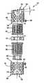
- FIG. 1shows a preferred embodiment of a spinal implant in its compressed state, designated generally as 10 .
- a spinal implantin its compressed state, designated generally as 10 .
- an upper outer sleeve 12 and a lower outer sleeve 14which, with their front surfaces 16 (see FIG. 2 ) facing each other, rest against a supporting ring 18 .
- outer sleeves 12 and 14have perforations 20 through which bone tissue can grow into the inside of the spinal implant 10 .
- Supporting ring 18has radially running openings 22 , through the inside cross-section 24 of which portions of teeth 26 can be seen. Also, the two outer sleeves 12 and 14 have outwardly oriented front surfaces 28 and 30 which have spinous extensions 32 that project in axial direction. These spinous extensions 32 penetrate the contact surfaces of the neighboring vertebrae and there anchor the two outer sleeves 12 and 14 .
- FIGS. 2 and 3show an upper inner sleeve 34 and a lower inner sleeve 36 which are screwed into the associated upper outer sleeve 12 and lower outer sleeve 14 .
- the figuresshow two set (grub) screws 38 which can be screwed into an associated tapped hole 40 of outer sleeves 12 and 14 , which affixes outer sleeves 12 and 14 to inner sleeves 34 and 36 .
- Tapped holes 40 for set screws 38are located in the immediate vicinity of front surfaces 16 of outer sleeves 12 and 14 .
- a locking element 42by means of which the two inner sleeves 34 and 36 can be attached to each other.
- the plane of front surface 28is inclined at an angle ⁇ to the orthogonal plane relative to longitudinal axis 44 . This makes it possible to optimally adjust spinal implant 10 to the position of the neighboring vertebrae or to correct the position of said vertebrae.
- an outer sleeve 12 or 14 having a front surface 28 or 30 , respectively, with the inclination requiredis selected.
- sleeves 12 , 14 , 34 , and 36 and supporting ring 18 and locking element 42are disposed coaxially with respect to one another and with respect to longitudinal axis 44 .
- FIGS. 4 and 5are enlarged representations of the two outer sleeves 12 and 14 , except that the inside thread 46 disposed on the inner circumference is only schematically shown or suggested.
- the inside threads 46are shown in FIG. 3 .
- This inside thread 46is, e.g., a fine thread with a pitch of 1 mm and a diameter of 22 mm, and is designed as a right-hand thread.
- FIGS. 4 and 5also show that a relatively large oblong perforation 48 is provided in the walls of outer sleeves 12 and 14 . After extensions, bone tissue can be filled into the inside of spinal implant 10 through perforation 48 .
- FIG. 6shows an enlarged perspective view of inner sleeves 34 and 36 which, along their outer circumference, have an outside thread 50 which again is only schematically shown or suggested. Outside thread 50 is shown in FIG. 3 .
- Inner sleeves 34 and 36also have perforations 52 .
- inner sleeves 34 and 36On one of their front surfaces 54 , inner sleeves 34 and 36 have a flange 56 which projects radially outwardly and which, on its outwardly oriented front surface, has teeth 26 which are preferably designed in the form of beveled teeth. In the longitudinal section shown in FIG. 7 , these beveled teeth can be clearly seen.
- flange 56has a shoulder 58 which projects radially inwardly and onto which detents 60 of a locking element 42 can latch.
- a locking element 42is shown in FIG. 9 .
- This locking element 42is also designed in the form of a sleeve and has, on its surface lying oppositely to detents 60 , a radially projecting retention flange 64 which comes to lie behind the associated shoulder 58 of the other inner sleeve 36 .
- the detentsare disposed on elastic tabs 68 , thus making it possible to deflect them radially toward the inside. In this manner, it is possible to connect the two inner sleeves 34 and 36 to each other.
- FIG. 8shows supporting ring 18 on which the two inner sleeves 34 and 36 with teeth 26 are seated.
- supporting ring 18has a shoulder 66 which projects radially inwardly and which is subdivided into a total of six segments.
- Shoulder 66is disposed in such a way as to intersect with openings 22 , with the diameter of openings 22 being greater than the thickness of shoulder 66 . This has the effect that part of teeth 26 project into the inside cross-section of openings 22 when inner sleeves 34 and 36 are resting on shoulder 66 . Teeth 26 can thus be accessed from the outside through opening 22 , as shown in FIGS. 1 and 2 .
- FIG. 10finally shows a tool 70 which has an oblong shape and a star-shaped cross-section.
- Tool 70also has teeth 72 which, together with teeth 26 , form a bevel tooth gear.
- the toolcan be disposed on a right rod or on a flexible shaft, thus making it easily possible for tool 70 to reach even difficult-to-access areas and to extend spinal implant 10 .
Landscapes
- Health & Medical Sciences (AREA)
- Engineering & Computer Science (AREA)
- Biomedical Technology (AREA)
- Orthopedic Medicine & Surgery (AREA)
- Transplantation (AREA)
- Heart & Thoracic Surgery (AREA)
- Oral & Maxillofacial Surgery (AREA)
- Cardiology (AREA)
- Neurology (AREA)
- Vascular Medicine (AREA)
- Life Sciences & Earth Sciences (AREA)
- Animal Behavior & Ethology (AREA)
- General Health & Medical Sciences (AREA)
- Public Health (AREA)
- Veterinary Medicine (AREA)
- Physical Education & Sports Medicine (AREA)
- Prostheses (AREA)
- Surgical Instruments (AREA)
Abstract
Description
Claims (15)
Applications Claiming Priority (3)
| Application Number | Priority Date | Filing Date | Title |
|---|---|---|---|
| DE10210214ADE10210214B4 (en) | 2002-03-02 | 2002-03-02 | Distractable spinal implant and tool for distraction |
| DE10210214.7 | 2002-03-02 | ||
| PCT/EP2003/000932WO2003073964A1 (en) | 2002-03-02 | 2003-01-30 | Distractible vertebral column implant and distracting tool |
Publications (2)
| Publication Number | Publication Date |
|---|---|
| US20040172129A1 US20040172129A1 (en) | 2004-09-02 |
| US7056343B2true US7056343B2 (en) | 2006-06-06 |
Family
ID=27771114
Family Applications (1)
| Application Number | Title | Priority Date | Filing Date |
|---|---|---|---|
| US10/476,811Expired - LifetimeUS7056343B2 (en) | 2002-03-02 | 2003-01-30 | Extendable spinal implant and extension tool |
Country Status (6)
| Country | Link |
|---|---|
| US (1) | US7056343B2 (en) |
| EP (1) | EP1361840B1 (en) |
| AT (1) | ATE305280T1 (en) |
| CA (1) | CA2455339C (en) |
| DE (2) | DE10210214B4 (en) |
| WO (1) | WO2003073964A1 (en) |
Cited By (59)
| Publication number | Priority date | Publication date | Assignee | Title |
|---|---|---|---|---|
| US20050071007A1 (en)* | 2003-09-30 | 2005-03-31 | Malek Michel H. | Intervertebral disc prosthesis |
| US20060136062A1 (en)* | 2004-12-17 | 2006-06-22 | Dinello Alexandre | Height-and angle-adjustable motion disc implant |
| US20070073395A1 (en)* | 2003-04-11 | 2007-03-29 | Daniel Baumgartner | Anchoring means for intervertebral implants |
| US20070179610A1 (en)* | 2005-12-23 | 2007-08-02 | Lutz Biedermann | Multi-walled placeholder |
| US20080009946A1 (en)* | 2006-06-20 | 2008-01-10 | Stephane Douget | Distractible intervertebral implant |
| US20080188941A1 (en)* | 2005-08-12 | 2008-08-07 | Innvotec Surgical, Inc. | Linearly expanding spine cage for enhanced spinal fusion |
| US20090112324A1 (en)* | 2007-10-30 | 2009-04-30 | Biospine, Llc | Vertebral body replacement device and method for use to maintain a space between two vertebral bodies within a spine |
| US20090112325A1 (en)* | 2007-10-30 | 2009-04-30 | Biospine, Llc | Footplate member and a method for use in a vertebral body replacement device |
| US20090118765A1 (en)* | 2003-03-24 | 2009-05-07 | Richard Mueller | Expandable Corpectomy Device |
| US7544208B1 (en)* | 2004-05-03 | 2009-06-09 | Theken Spine, Llc | Adjustable corpectomy apparatus |
| US20090164018A1 (en)* | 2007-12-19 | 2009-06-25 | Robert Sommerich | Instruments For Expandable Corpectomy Spinal Fusion Cage |
| US20090164017A1 (en)* | 2007-12-19 | 2009-06-25 | Robert Sommerich | Expandable Corpectomy Spinal Fusion Cage |
| US20100094424A1 (en)* | 2007-03-13 | 2010-04-15 | William Woodburn | Adjustable intervertebral implant |
| US20100121378A1 (en)* | 2008-11-10 | 2010-05-13 | Malek Michel H | Facet fusion system |
| US20100160964A1 (en)* | 2008-12-18 | 2010-06-24 | Malek Michel H | Flexible spinal stabilization system |
| US20100179594A1 (en)* | 2008-03-28 | 2010-07-15 | Charles Theofilos | Expandable cage |
| US20100179657A1 (en)* | 2009-01-14 | 2010-07-15 | Stout Medical Group, L.P. | Expandable support device and method of use |
| US20100179656A1 (en)* | 2008-03-28 | 2010-07-15 | Charles Theofilos | Expandable cage with locking device |
| US20100211119A1 (en)* | 2009-02-19 | 2010-08-19 | Daniel Refai | Multi-functional surgical instrument and method of use for inserting an implant between two bones |
| US20100280616A1 (en)* | 2009-04-29 | 2010-11-04 | William Frasier | Minimally invasive corpectomy cage and instrument |
| US7935133B2 (en) | 2008-02-08 | 2011-05-03 | Mmsn Limited Partnership | Interlaminar hook |
| US20110166602A1 (en)* | 2006-07-28 | 2011-07-07 | Malek Michel H | Bone anchor device |
| US20110184523A1 (en)* | 2010-01-27 | 2011-07-28 | Warsaw Orthopedic, Inc. | Slide-on end cap for a vertebral implant |
| US20110208306A1 (en)* | 2009-11-10 | 2011-08-25 | Zimmer Spine, Inc. | Tissue spacer implant, implant tool, and methods of use thereof |
| US20110251692A1 (en)* | 2010-04-12 | 2011-10-13 | Mclaughlin Colm | Expandable Vertebral Implant |
| US20120022654A1 (en)* | 2009-04-13 | 2012-01-26 | Biospine, Llc | Variable height intervertebral devices and methods for use |
| US8142441B2 (en) | 2008-10-16 | 2012-03-27 | Aesculap Implant Systems, Llc | Surgical instrument and method of use for inserting an implant between two bones |
| US20120116457A1 (en)* | 2010-11-06 | 2012-05-10 | Limited Liability Company; | Stabilizer for assisting stabilization of a spinal implant and method of using the stabilizer |
| US8211178B2 (en) | 2009-06-18 | 2012-07-03 | Warsaw Orthopedic | Intervertebral implant with a pivoting end cap |
| US8377140B2 (en) | 2011-01-12 | 2013-02-19 | Ebi, Llc | Expandable spinal implant device |
| WO2013025448A1 (en)* | 2011-08-09 | 2013-02-21 | Nuvasive, Inc. | Vertebral body replacement |
| US8486113B2 (en) | 2003-11-25 | 2013-07-16 | Michel H. Malek | Spinal stabilization systems |
| US20130268079A1 (en)* | 2010-11-06 | 2013-10-10 | Igip, Llc | Stabilizer For Assisting Stabilization Of A Spinal Implant |
| US8568482B2 (en) | 2003-05-14 | 2013-10-29 | Kilian Kraus | Height-adjustable implant to be inserted between vertebral bodies and corresponding handling tool |
| US8591587B2 (en) | 2007-10-30 | 2013-11-26 | Aesculap Implant Systems, Llc | Vertebral body replacement device and method for use to maintain a space between two vertebral bodies within a spine |
| US8617214B2 (en) | 2008-01-07 | 2013-12-31 | Mmsn Limited Partnership | Spinal tension band |
| US8740980B2 (en) | 2011-01-27 | 2014-06-03 | Warsaw Orthopedic, Inc. | Expandable medical implant |
| US9138217B2 (en) | 2009-11-11 | 2015-09-22 | Nu Vasive, Inc. | Surgical access system and related methods |
| US9211193B2 (en) | 2013-08-30 | 2015-12-15 | Aesculap Implant Systems, Llc | Prosthesis, system and method |
| US9301787B2 (en) | 2010-09-27 | 2016-04-05 | Mmsn Limited Partnership | Medical apparatus and method for spinal surgery |
| WO2016057447A1 (en)* | 2014-10-09 | 2016-04-14 | Warsaw Orthopedic, Inc. | Spinal implant system and method |
| US9387090B2 (en) | 2009-03-12 | 2016-07-12 | Nuvasive, Inc. | Vertebral body replacement |
| US9566167B2 (en) | 2013-08-22 | 2017-02-14 | K2M, Inc. | Expandable spinal implant |
| US9687357B2 (en) | 2009-03-12 | 2017-06-27 | Nuvasive, Inc. | Vertebral body replacement |
| US9707091B2 (en) | 2010-04-12 | 2017-07-18 | Globus Medical, Inc. | Expandable vertebral implant |
| US9707096B2 (en) | 2013-03-14 | 2017-07-18 | K2M, Inc. | Spinal fixation device |
| US9808349B2 (en) | 2010-04-12 | 2017-11-07 | Globus Medical Inc | Expandable vertebral implant |
| US9913735B2 (en) | 2010-04-12 | 2018-03-13 | Globus Medical, Inc. | Angling inserter tool for expandable vertebral implant |
| US9968460B2 (en) | 2013-03-15 | 2018-05-15 | Medsmart Innovation Inc. | Dynamic spinal segment replacement |
| US10130489B2 (en) | 2010-04-12 | 2018-11-20 | Globus Medical, Inc. | Expandable vertebral implant |
| US10292832B2 (en) | 2013-03-14 | 2019-05-21 | Ohio State Innovation Foundation | Spinal fixation device |
| US10327908B2 (en) | 2015-09-18 | 2019-06-25 | K2M, Inc. | Corpectomy device and methods of use thereof |
| US10363142B2 (en) | 2014-12-11 | 2019-07-30 | K2M, Inc. | Expandable spinal implants |
| US10441430B2 (en) | 2017-07-24 | 2019-10-15 | K2M, Inc. | Expandable spinal implants |
| US11278424B2 (en) | 2016-11-28 | 2022-03-22 | Musc Foundaton For Research Development | Expandable vertebral body replacement device and method |
| US11426287B2 (en) | 2010-04-12 | 2022-08-30 | Globus Medical Inc. | Expandable vertebral implant |
| US11452612B2 (en)* | 2014-10-09 | 2022-09-27 | Warsaw Orthopedic, Inc. | Spinal implant system and method |
| US11602436B2 (en) | 2015-03-23 | 2023-03-14 | Musc Foundation For Research Development | Expandable vertebral body replacement device and method |
| US12295858B2 (en) | 2020-02-24 | 2025-05-13 | Musc Foundation For Research Development | Expandable vertebral body replacement device and method |
Families Citing this family (32)
| Publication number | Priority date | Publication date | Assignee | Title |
|---|---|---|---|---|
| DE10324108B3 (en)* | 2003-05-21 | 2005-01-27 | Aesculap Ag & Co. Kg | Backbone implant is inserted with contracted contact disc which is expanded to optimum area following insertion |
| DE10328307A1 (en)* | 2003-06-23 | 2005-02-03 | Franz Rennebaum | Vertebral prosthesis |
| US7819922B2 (en) | 2003-10-16 | 2010-10-26 | Spinal Generations, Llc | Vertebral prosthesis |
| DE102004021861A1 (en)* | 2004-05-04 | 2005-11-24 | Biedermann Motech Gmbh | Implant for temporary or permanent replacement of vertebra or intervertebral disk, comprising solid central element and outer elements with openings |
| US7285134B2 (en)* | 2003-10-22 | 2007-10-23 | Warsaw Orthopedic, Inc. | Vertebral body replacement implant |
| DE10357926B3 (en)* | 2003-12-11 | 2005-09-01 | Deltacor Gmbh | Length adjustable spinal implant |
| US20050200696A1 (en)* | 2004-03-09 | 2005-09-15 | Audiovox Corporation | Display device mountable in a vehicle |
| US7883543B2 (en)* | 2004-10-01 | 2011-02-08 | Spinal Generations, Llc | Vertebral prosthesis and spinal fixation system |
| US20070270960A1 (en)* | 2006-04-24 | 2007-11-22 | Sdgi Holdings, Inc. | Extendable anchor in a vertebral implant and methods of use |
| US8657882B2 (en)* | 2006-04-24 | 2014-02-25 | Warsaw Orthopedic, Inc. | Expandable intervertebral devices and methods of use |
| US7879096B2 (en)* | 2006-04-27 | 2011-02-01 | Warsaw Orthopedic, Inc. | Centrally driven expandable implant |
| US7575601B2 (en)* | 2006-04-27 | 2009-08-18 | Warsaw Orthopedic, Inc. | Locking expandable implant and method |
| US7981157B2 (en)* | 2006-04-27 | 2011-07-19 | Warsaw Orthopedic, Inc. | Self-contained expandable implant and method |
| US7794501B2 (en)* | 2006-04-27 | 2010-09-14 | Wasaw Orthopedic, Inc. | Expandable intervertebral spacers and methods of use |
| US7914581B2 (en)* | 2006-04-27 | 2011-03-29 | Warsaw Orthopedic, Inc. | Expandable implant, instrument, and method |
| US8187331B2 (en) | 2006-04-27 | 2012-05-29 | Warsaw Orthopedic, Inc. | Expandable vertebral implant and methods of use |
| US7758648B2 (en)* | 2006-04-27 | 2010-07-20 | Warsaw Orthopedic, Inc. | Stabilized, adjustable expandable implant and method |
| US7708779B2 (en) | 2006-05-01 | 2010-05-04 | Warsaw Orthopedic, Inc. | Expandable intervertebral spacers and methods of use |
| ES2395298T3 (en) | 2006-07-14 | 2013-02-11 | Biedermann Technologies Gmbh & Co. Kg | Separator for insertion between two vertebrae |
| US7815683B2 (en)* | 2006-10-16 | 2010-10-19 | Warsaw Orthopedic, Inc. | Implants with helical supports and methods of use for spacing vertebral members |
| US9023107B2 (en)* | 2006-11-08 | 2015-05-05 | Spinal Usa, Inc. | Vertebral body replacement |
| US8920502B1 (en)* | 2006-11-08 | 2014-12-30 | Spinal Usa, Inc. | Vertebral body replacement |
| EP2131790B1 (en) | 2007-02-22 | 2012-10-24 | Kyphon SÀRL | Expandable devices for emplacement in bone and other body parts |
| DE102007052042A1 (en)* | 2007-10-30 | 2009-05-14 | Kilian Kraus | Height-adjustable spine implant |
| US8123809B2 (en)* | 2009-04-16 | 2012-02-28 | Warsaw Orthopedic, Inc. | Deployment system and method for an expandable vertebral implant |
| US8292963B2 (en) | 2009-04-23 | 2012-10-23 | Warsaw Orthopedic, Inc. | Expandable implant for supporting skeletal structures |
| GB201006173D0 (en) | 2010-04-14 | 2010-06-02 | Depuy Ireland | A distractor |
| DE102011002076A1 (en)* | 2011-04-15 | 2012-10-18 | Z.-Medical Gmbh & Co. Kg | Intervertebral implant and device for insertion |
| GB201115411D0 (en) | 2011-09-07 | 2011-10-19 | Depuy Ireland | Surgical instrument |
| CN107041800A (en)* | 2017-01-21 | 2017-08-15 | 张洪剑 | The artificial spinal devices of New type detachable |
| US11678894B2 (en) | 2017-12-15 | 2023-06-20 | Jonathan P. Cabot | Knee balancing instrument |
| US11135070B2 (en) | 2018-02-14 | 2021-10-05 | Titan Spine, Inc. | Modular adjustable corpectomy cage |
Citations (21)
| Publication number | Priority date | Publication date | Assignee | Title |
|---|---|---|---|---|
| US4553273A (en) | 1983-11-23 | 1985-11-19 | Henry Ford Hospital | Vertebral body prosthesis and spine stabilizing method |
| US5236460A (en)* | 1990-02-12 | 1993-08-17 | Midas Rex Pneumatic Tools, Inc. | Vertebral body prosthesis |
| EP0567424A1 (en) | 1992-04-24 | 1993-10-27 | Bilbao Ortiz de Zarate, José Ramon | Vertebral prosthesis for the substitution of a vertebra in malignant tumour surgery |
| DE19519101A1 (en) | 1995-05-24 | 1996-11-28 | Harms Juergen | Height-adjustable vertebral body replacement |
| US5702455A (en)* | 1996-07-03 | 1997-12-30 | Saggar; Rahul | Expandable prosthesis for spinal fusion |
| US5776198A (en)* | 1994-12-09 | 1998-07-07 | Sdgi Holdings, Inc. | Adjustable vertebral body replacement |
| WO1998044878A1 (en) | 1997-04-07 | 1998-10-15 | Sitiso, Arthit | Anterior spinal implant system for vertebrae replacement |
| WO1998046173A1 (en) | 1997-04-15 | 1998-10-22 | Synthes Ag Chur | Telescopic vertebral prosthesis |
| EP0950388A2 (en) | 1998-04-16 | 1999-10-20 | Ulrich GmbH & Co. KG | Implant for the insertion between the vertebraes of the spine |
| US6015436A (en)* | 1996-06-07 | 2000-01-18 | Heinrich Ulrich | Implant for filling a space between vertebrae |
| US6190414B1 (en)* | 1996-10-31 | 2001-02-20 | Surgical Dynamics Inc. | Apparatus for fusion of adjacent bone structures |
| US6193756B1 (en)* | 1997-09-30 | 2001-02-27 | Sulzer Orthopaedie Ag | Tubular support body for bridging two vertebrae |
| EP1080703A2 (en) | 1999-09-02 | 2001-03-07 | Howmedica Osteonics Corp. | Spinal implant |
| DE4423257C2 (en) | 1994-07-02 | 2001-07-12 | Ulrich Heinrich | Implant to be inserted between the vertebral body of the spine as a placeholder |
| WO2001072246A1 (en) | 2000-03-31 | 2001-10-04 | Königsee Implantate und Instrumente zur Osteosynthese GmbH | Variable-height vertebral implant |
| US6299644B1 (en)* | 1997-06-16 | 2001-10-09 | Paul Vanderschot | Vertebral replacement implant |
| US20010056302A1 (en)* | 2000-03-22 | 2001-12-27 | Boyer Michael L. | Skeletal reconstruction cages |
| US6524341B2 (en)* | 1998-10-15 | 2003-02-25 | Synthes (Usa) | Telescopic vertebral prosthesis |
| US20040049271A1 (en)* | 2001-08-03 | 2004-03-11 | Lutz Biedermann | Spacer having a variable axial length |
| US6719796B2 (en)* | 1999-07-26 | 2004-04-13 | Advanced Prosthetic Technologies, Inc. | Spinal surgical prosthesis |
| US6752832B2 (en)* | 2000-12-27 | 2004-06-22 | Ulrich Gmbh & Co., Kg | Vertebral implant and setting tool therefor |
Family Cites Families (1)
| Publication number | Priority date | Publication date | Assignee | Title |
|---|---|---|---|---|
| FR2575059B1 (en)* | 1984-12-21 | 1988-11-10 | Daher Youssef | SHORING DEVICE FOR USE IN A VERTEBRAL PROSTHESIS |
- 2002
- 2002-03-02DEDE10210214Apatent/DE10210214B4/ennot_activeExpired - Lifetime
- 2003
- 2003-01-30CACA002455339Apatent/CA2455339C/ennot_activeExpired - Fee Related
- 2003-01-30DEDE50301242Tpatent/DE50301242D1/ennot_activeExpired - Lifetime
- 2003-01-30ATAT03743307Tpatent/ATE305280T1/enactive
- 2003-01-30EPEP03743307Apatent/EP1361840B1/ennot_activeExpired - Lifetime
- 2003-01-30USUS10/476,811patent/US7056343B2/ennot_activeExpired - Lifetime
- 2003-01-30WOPCT/EP2003/000932patent/WO2003073964A1/enactiveIP Right Grant
Patent Citations (23)
| Publication number | Priority date | Publication date | Assignee | Title |
|---|---|---|---|---|
| US4553273A (en) | 1983-11-23 | 1985-11-19 | Henry Ford Hospital | Vertebral body prosthesis and spine stabilizing method |
| US5236460A (en)* | 1990-02-12 | 1993-08-17 | Midas Rex Pneumatic Tools, Inc. | Vertebral body prosthesis |
| EP0567424A1 (en) | 1992-04-24 | 1993-10-27 | Bilbao Ortiz de Zarate, José Ramon | Vertebral prosthesis for the substitution of a vertebra in malignant tumour surgery |
| DE4423257C2 (en) | 1994-07-02 | 2001-07-12 | Ulrich Heinrich | Implant to be inserted between the vertebral body of the spine as a placeholder |
| US5776198A (en)* | 1994-12-09 | 1998-07-07 | Sdgi Holdings, Inc. | Adjustable vertebral body replacement |
| DE19519101A1 (en) | 1995-05-24 | 1996-11-28 | Harms Juergen | Height-adjustable vertebral body replacement |
| US6015436A (en)* | 1996-06-07 | 2000-01-18 | Heinrich Ulrich | Implant for filling a space between vertebrae |
| US5702455A (en)* | 1996-07-03 | 1997-12-30 | Saggar; Rahul | Expandable prosthesis for spinal fusion |
| US6190414B1 (en)* | 1996-10-31 | 2001-02-20 | Surgical Dynamics Inc. | Apparatus for fusion of adjacent bone structures |
| WO1998044878A1 (en) | 1997-04-07 | 1998-10-15 | Sitiso, Arthit | Anterior spinal implant system for vertebrae replacement |
| WO1998046173A1 (en) | 1997-04-15 | 1998-10-22 | Synthes Ag Chur | Telescopic vertebral prosthesis |
| US6299644B1 (en)* | 1997-06-16 | 2001-10-09 | Paul Vanderschot | Vertebral replacement implant |
| US6193756B1 (en)* | 1997-09-30 | 2001-02-27 | Sulzer Orthopaedie Ag | Tubular support body for bridging two vertebrae |
| EP0950388A2 (en) | 1998-04-16 | 1999-10-20 | Ulrich GmbH & Co. KG | Implant for the insertion between the vertebraes of the spine |
| DE19816782A1 (en) | 1998-04-16 | 1999-10-28 | Ulrich Gmbh & Co Kg | Implant for insertion between the vertebral body of the spine |
| US6524341B2 (en)* | 1998-10-15 | 2003-02-25 | Synthes (Usa) | Telescopic vertebral prosthesis |
| US6719796B2 (en)* | 1999-07-26 | 2004-04-13 | Advanced Prosthetic Technologies, Inc. | Spinal surgical prosthesis |
| EP1080703A2 (en) | 1999-09-02 | 2001-03-07 | Howmedica Osteonics Corp. | Spinal implant |
| US20010056302A1 (en)* | 2000-03-22 | 2001-12-27 | Boyer Michael L. | Skeletal reconstruction cages |
| WO2001072246A1 (en) | 2000-03-31 | 2001-10-04 | Königsee Implantate und Instrumente zur Osteosynthese GmbH | Variable-height vertebral implant |
| US20030163199A1 (en)* | 2000-03-31 | 2003-08-28 | Heinrich Boehm | Variable height vertebral implant |
| US6752832B2 (en)* | 2000-12-27 | 2004-06-22 | Ulrich Gmbh & Co., Kg | Vertebral implant and setting tool therefor |
| US20040049271A1 (en)* | 2001-08-03 | 2004-03-11 | Lutz Biedermann | Spacer having a variable axial length |
Cited By (127)
| Publication number | Priority date | Publication date | Assignee | Title |
|---|---|---|---|---|
| US20090118765A1 (en)* | 2003-03-24 | 2009-05-07 | Richard Mueller | Expandable Corpectomy Device |
| US8152851B2 (en) | 2003-03-24 | 2012-04-10 | Theken Spine, Llc | Expandable corpectomy device |
| US7918876B2 (en) | 2003-03-24 | 2011-04-05 | Theken Spine, Llc | Spinal implant adjustment device |
| US20070073395A1 (en)* | 2003-04-11 | 2007-03-29 | Daniel Baumgartner | Anchoring means for intervertebral implants |
| US7628815B2 (en)* | 2003-04-11 | 2009-12-08 | Synthes Usa, Llc | Intervertebral implant with moveable endcaps |
| US8568482B2 (en) | 2003-05-14 | 2013-10-29 | Kilian Kraus | Height-adjustable implant to be inserted between vertebral bodies and corresponding handling tool |
| US8097038B2 (en) | 2003-09-30 | 2012-01-17 | Mmsn Limited Partnership | Prosthetic vertebral assembly |
| US20050071007A1 (en)* | 2003-09-30 | 2005-03-31 | Malek Michel H. | Intervertebral disc prosthesis |
| US7402176B2 (en) | 2003-09-30 | 2008-07-22 | Malek Michel H | Intervertebral disc prosthesis |
| US20070185577A1 (en)* | 2003-09-30 | 2007-08-09 | Malek Michel H | Intervertebral disc prosthesis |
| US7255714B2 (en)* | 2003-09-30 | 2007-08-14 | Michel H. Malek | Vertically adjustable intervertebral disc prosthesis |
| US8486113B2 (en) | 2003-11-25 | 2013-07-16 | Michel H. Malek | Spinal stabilization systems |
| US7544208B1 (en)* | 2004-05-03 | 2009-06-09 | Theken Spine, Llc | Adjustable corpectomy apparatus |
| US20060136062A1 (en)* | 2004-12-17 | 2006-06-22 | Dinello Alexandre | Height-and angle-adjustable motion disc implant |
| US20080188941A1 (en)* | 2005-08-12 | 2008-08-07 | Innvotec Surgical, Inc. | Linearly expanding spine cage for enhanced spinal fusion |
| US7819921B2 (en) | 2005-08-12 | 2010-10-26 | Coalign Innovations, Inc. | Linearly expanding spine cage for enhanced spinal fusion |
| US7722674B1 (en) | 2005-08-12 | 2010-05-25 | Innvotec Surgical Inc. | Linearly expanding spine cage for enhanced spinal fusion |
| US9814595B2 (en) | 2005-12-23 | 2017-11-14 | Biedermann Technologies Gmbh & Co. Kg. | Multi-walled placeholder |
| US11083589B2 (en) | 2005-12-23 | 2021-08-10 | Biedermann Technologies Gmbh & Co. Kg | Multi-walled placeholder |
| US9254199B2 (en) | 2005-12-23 | 2016-02-09 | Biedermann Technologies GmbH & Co., KG | Multi-walled placeholder |
| US10130485B2 (en) | 2005-12-23 | 2018-11-20 | Biedermann Technologies Gmbh & Co. Kg | Multi-walled placeholder |
| US20070179610A1 (en)* | 2005-12-23 | 2007-08-02 | Lutz Biedermann | Multi-walled placeholder |
| US11883299B2 (en) | 2005-12-23 | 2024-01-30 | Biedermann Technologies Gmbh & Co. Kg | Multi-walled placeholder |
| US7887596B2 (en) | 2006-06-20 | 2011-02-15 | Zimmer Spine S.A.S. | Distractible intervertebral implant |
| US20080009946A1 (en)* | 2006-06-20 | 2008-01-10 | Stephane Douget | Distractible intervertebral implant |
| US20110166602A1 (en)* | 2006-07-28 | 2011-07-07 | Malek Michel H | Bone anchor device |
| US8992617B2 (en)* | 2007-03-13 | 2015-03-31 | DePuy Synthes Products, LLC | Adjustable intervertebral implant |
| US20100094424A1 (en)* | 2007-03-13 | 2010-04-15 | William Woodburn | Adjustable intervertebral implant |
| US8591587B2 (en) | 2007-10-30 | 2013-11-26 | Aesculap Implant Systems, Llc | Vertebral body replacement device and method for use to maintain a space between two vertebral bodies within a spine |
| US20090112325A1 (en)* | 2007-10-30 | 2009-04-30 | Biospine, Llc | Footplate member and a method for use in a vertebral body replacement device |
| US20090112324A1 (en)* | 2007-10-30 | 2009-04-30 | Biospine, Llc | Vertebral body replacement device and method for use to maintain a space between two vertebral bodies within a spine |
| US10806595B2 (en) | 2007-10-30 | 2020-10-20 | Aesculap Implant Systems, Llc | Vertebral body replacement device and method for use to maintain a space between two vertebral bodies within a spine |
| US8690950B2 (en) | 2007-10-30 | 2014-04-08 | Aesculap Implant Systems, Llc | Vertebral body replacement device and method for use to maintain a space between two vertebral bodies within a spine |
| US10881527B2 (en) | 2007-10-30 | 2021-01-05 | Aesculap Implant Systems, Llc | Vertebral body replacement device and method for use to maintain a space between two vertebral bodies within a spine |
| US10201432B2 (en) | 2007-10-30 | 2019-02-12 | Aesculap Implant Systems, Llc | Vertebral body replacement device and method for use to maintain a space between two vertebral bodies within a spine |
| US8182537B2 (en) | 2007-10-30 | 2012-05-22 | Aesculap Implant Systems, Llc | Vertebral body replacement device and method for use to maintain a space between two vertebral bodies within a spine |
| US9034046B2 (en) | 2007-10-30 | 2015-05-19 | Aesculap Implant Systems, Llc | Vertebral body replacement device and method for use to maintain a space between two vertebral bodies within a spine |
| US20090164017A1 (en)* | 2007-12-19 | 2009-06-25 | Robert Sommerich | Expandable Corpectomy Spinal Fusion Cage |
| US20090164018A1 (en)* | 2007-12-19 | 2009-06-25 | Robert Sommerich | Instruments For Expandable Corpectomy Spinal Fusion Cage |
| USRE46261E1 (en) | 2007-12-19 | 2017-01-03 | DePuy Synthes Products, Inc. | Instruments for expandable corpectomy spinal fusion cage |
| US8241363B2 (en) | 2007-12-19 | 2012-08-14 | Depuy Spine, Inc. | Expandable corpectomy spinal fusion cage |
| US8241294B2 (en) | 2007-12-19 | 2012-08-14 | Depuy Spine, Inc. | Instruments for expandable corpectomy spinal fusion cage |
| US8617214B2 (en) | 2008-01-07 | 2013-12-31 | Mmsn Limited Partnership | Spinal tension band |
| US7935133B2 (en) | 2008-02-08 | 2011-05-03 | Mmsn Limited Partnership | Interlaminar hook |
| US20100179594A1 (en)* | 2008-03-28 | 2010-07-15 | Charles Theofilos | Expandable cage |
| US8585761B2 (en) | 2008-03-28 | 2013-11-19 | K2M, Inc. | Expandable cage with locking device |
| US20100179656A1 (en)* | 2008-03-28 | 2010-07-15 | Charles Theofilos | Expandable cage with locking device |
| US9539107B2 (en) | 2008-03-28 | 2017-01-10 | K2M, Inc. | Expandable cage |
| US8673011B2 (en) | 2008-03-28 | 2014-03-18 | K2M, Inc. | Expandable cage |
| US8702719B2 (en)* | 2008-10-16 | 2014-04-22 | Aesculap Implant Systems, Llc | Surgical instrument and method of use for inserting an implant between two bones |
| US8142441B2 (en) | 2008-10-16 | 2012-03-27 | Aesculap Implant Systems, Llc | Surgical instrument and method of use for inserting an implant between two bones |
| US20100121378A1 (en)* | 2008-11-10 | 2010-05-13 | Malek Michel H | Facet fusion system |
| US8187304B2 (en) | 2008-11-10 | 2012-05-29 | Malek Michel H | Facet fusion system |
| US20100160964A1 (en)* | 2008-12-18 | 2010-06-24 | Malek Michel H | Flexible spinal stabilization system |
| US9492214B2 (en) | 2008-12-18 | 2016-11-15 | Michel H. Malek | Flexible spinal stabilization system |
| US8252054B2 (en) | 2009-01-14 | 2012-08-28 | Stout Medical Group, L.P. | Expandable support device and method of use |
| US20100179657A1 (en)* | 2009-01-14 | 2010-07-15 | Stout Medical Group, L.P. | Expandable support device and method of use |
| US20100211119A1 (en)* | 2009-02-19 | 2010-08-19 | Daniel Refai | Multi-functional surgical instrument and method of use for inserting an implant between two bones |
| US8142435B2 (en) | 2009-02-19 | 2012-03-27 | Aesculap Implant Systems, Llc | Multi-functional surgical instrument and method of use for inserting an implant between two bones |
| US9687357B2 (en) | 2009-03-12 | 2017-06-27 | Nuvasive, Inc. | Vertebral body replacement |
| US11712344B2 (en) | 2009-03-12 | 2023-08-01 | Nuvasive, Inc. | Vertebral body replacement |
| US10390960B2 (en) | 2009-03-12 | 2019-08-27 | Nuvasive, Inc. | Vertebral body replacement |
| US11458025B2 (en) | 2009-03-12 | 2022-10-04 | Nuvasive, Inc. | Vertebral body replacement |
| US10413421B2 (en) | 2009-03-12 | 2019-09-17 | Nuvasive, Inc. | Vertebral body replacement |
| US9387090B2 (en) | 2009-03-12 | 2016-07-12 | Nuvasive, Inc. | Vertebral body replacement |
| US12350169B2 (en) | 2009-03-12 | 2025-07-08 | Nuvasive, Inc. | Vertebral body replacement |
| US9636233B2 (en) | 2009-03-12 | 2017-05-02 | Nuvasive, Inc. | Vertebral body replacement |
| US20120022654A1 (en)* | 2009-04-13 | 2012-01-26 | Biospine, Llc | Variable height intervertebral devices and methods for use |
| US8840669B2 (en)* | 2009-04-13 | 2014-09-23 | Biomet Spine, Llc | Variable height intervertebral devices and methods for use |
| US20100280616A1 (en)* | 2009-04-29 | 2010-11-04 | William Frasier | Minimally invasive corpectomy cage and instrument |
| US8876905B2 (en) | 2009-04-29 | 2014-11-04 | DePuy Synthes Products, LLC | Minimally invasive corpectomy cage and instrument |
| US8211178B2 (en) | 2009-06-18 | 2012-07-03 | Warsaw Orthopedic | Intervertebral implant with a pivoting end cap |
| US10092410B2 (en) | 2009-11-10 | 2018-10-09 | Medivest, Llc | Methods of using a vertebral body replacement device |
| US9295559B2 (en) | 2009-11-10 | 2016-03-29 | Medivest, Llc | Tissue spacer implant |
| US9125750B2 (en) | 2009-11-10 | 2015-09-08 | Medivest, Llc | Methods of using a vertebral body replacement device |
| US20110208306A1 (en)* | 2009-11-10 | 2011-08-25 | Zimmer Spine, Inc. | Tissue spacer implant, implant tool, and methods of use thereof |
| US9138217B2 (en) | 2009-11-11 | 2015-09-22 | Nu Vasive, Inc. | Surgical access system and related methods |
| US20110184523A1 (en)* | 2010-01-27 | 2011-07-28 | Warsaw Orthopedic, Inc. | Slide-on end cap for a vertebral implant |
| US8268002B2 (en)* | 2010-01-27 | 2012-09-18 | Warsaw Orthopedic, Inc. | Slide-on end cap for a vertebral implant |
| US12279971B2 (en) | 2010-04-12 | 2025-04-22 | Globus Medical, Inc. | Angling inserter tool for expandable vertebral implant |
| US11426287B2 (en) | 2010-04-12 | 2022-08-30 | Globus Medical Inc. | Expandable vertebral implant |
| US9707091B2 (en) | 2010-04-12 | 2017-07-18 | Globus Medical, Inc. | Expandable vertebral implant |
| US10492928B2 (en) | 2010-04-12 | 2019-12-03 | Globus Medical, Inc. | Angling inserter tool for expandable vertebral implant |
| US9808349B2 (en) | 2010-04-12 | 2017-11-07 | Globus Medical Inc | Expandable vertebral implant |
| US10500057B2 (en) | 2010-04-12 | 2019-12-10 | Globus Medical, Inc. | Expandable vertebral implant |
| US9913735B2 (en) | 2010-04-12 | 2018-03-13 | Globus Medical, Inc. | Angling inserter tool for expandable vertebral implant |
| US20110251692A1 (en)* | 2010-04-12 | 2011-10-13 | Mclaughlin Colm | Expandable Vertebral Implant |
| US9474621B2 (en) | 2010-04-12 | 2016-10-25 | Globus Medical, Inc. | Expandable vertebral implant |
| US9579211B2 (en)* | 2010-04-12 | 2017-02-28 | Globus Medical, Inc. | Expandable vertebral implant |
| US10369000B2 (en) | 2010-04-12 | 2019-08-06 | Globus Medical, Inc. | Expandable vertebral implant |
| US10130489B2 (en) | 2010-04-12 | 2018-11-20 | Globus Medical, Inc. | Expandable vertebral implant |
| US11298243B2 (en) | 2010-04-12 | 2022-04-12 | Globus Medical, Inc. | Angling inserter tool for expandable vertebral implant |
| US11564803B2 (en) | 2010-04-12 | 2023-01-31 | Globus Medical, Inc. | Expandable vertebral implant |
| US9301787B2 (en) | 2010-09-27 | 2016-04-05 | Mmsn Limited Partnership | Medical apparatus and method for spinal surgery |
| US9084684B2 (en)* | 2010-11-06 | 2015-07-21 | Igip, Llc | Stabilizer for assisting stabilization of a spinal implant |
| US20130268079A1 (en)* | 2010-11-06 | 2013-10-10 | Igip, Llc | Stabilizer For Assisting Stabilization Of A Spinal Implant |
| US20120116457A1 (en)* | 2010-11-06 | 2012-05-10 | Limited Liability Company; | Stabilizer for assisting stabilization of a spinal implant and method of using the stabilizer |
| US8377140B2 (en) | 2011-01-12 | 2013-02-19 | Ebi, Llc | Expandable spinal implant device |
| US9050195B2 (en) | 2011-01-12 | 2015-06-09 | Ebi, Llc | Expandable spinal implant device |
| US8740980B2 (en) | 2011-01-27 | 2014-06-03 | Warsaw Orthopedic, Inc. | Expandable medical implant |
| US8801788B2 (en) | 2011-01-27 | 2014-08-12 | Warsaw Orthopedic, Inc. | Expandable medical implant |
| WO2013025448A1 (en)* | 2011-08-09 | 2013-02-21 | Nuvasive, Inc. | Vertebral body replacement |
| US10292832B2 (en) | 2013-03-14 | 2019-05-21 | Ohio State Innovation Foundation | Spinal fixation device |
| US11173041B2 (en) | 2013-03-14 | 2021-11-16 | Ohio State Innovation Foundation | Spinal fixation device |
| US9707096B2 (en) | 2013-03-14 | 2017-07-18 | K2M, Inc. | Spinal fixation device |
| US12220325B2 (en) | 2013-03-14 | 2025-02-11 | K2M, Inc. | Spinal fixation device |
| US9968460B2 (en) | 2013-03-15 | 2018-05-15 | Medsmart Innovation Inc. | Dynamic spinal segment replacement |
| US9566167B2 (en) | 2013-08-22 | 2017-02-14 | K2M, Inc. | Expandable spinal implant |
| US9211193B2 (en) | 2013-08-30 | 2015-12-15 | Aesculap Implant Systems, Llc | Prosthesis, system and method |
| US9974663B2 (en) | 2014-10-09 | 2018-05-22 | Warsaw Orthopedic, Inc. | Spinal implant system and method |
| WO2016057447A1 (en)* | 2014-10-09 | 2016-04-14 | Warsaw Orthopedic, Inc. | Spinal implant system and method |
| US11357641B2 (en) | 2014-10-09 | 2022-06-14 | Warsaw Orthopedic, Inc. | Spinal implant system and method |
| US10624759B2 (en) | 2014-10-09 | 2020-04-21 | Warsaw Orthopedic, Inc. | Spinal implant system and method |
| US11452612B2 (en)* | 2014-10-09 | 2022-09-27 | Warsaw Orthopedic, Inc. | Spinal implant system and method |
| US12042400B2 (en) | 2014-10-09 | 2024-07-23 | Warsaw Orthopedic, Inc. | Spinal implant system and method |
| US11331200B2 (en) | 2014-12-11 | 2022-05-17 | K2M, Inc. | Expandable spinal implants |
| US10363142B2 (en) | 2014-12-11 | 2019-07-30 | K2M, Inc. | Expandable spinal implants |
| US12257159B2 (en) | 2014-12-11 | 2025-03-25 | K2M, Inc. | Expandable spinal implants |
| US11602436B2 (en) | 2015-03-23 | 2023-03-14 | Musc Foundation For Research Development | Expandable vertebral body replacement device and method |
| US12239545B2 (en) | 2015-03-23 | 2025-03-04 | Musc Foundation For Research Development | Expandable vertebral body replacement device and method |
| US10327908B2 (en) | 2015-09-18 | 2019-06-25 | K2M, Inc. | Corpectomy device and methods of use thereof |
| US11344426B2 (en) | 2015-09-18 | 2022-05-31 | K2M, Inc. | Corpectomy device and methods of use thereof |
| US11278424B2 (en) | 2016-11-28 | 2022-03-22 | Musc Foundaton For Research Development | Expandable vertebral body replacement device and method |
| US12029662B2 (en) | 2017-07-24 | 2024-07-09 | K2M, Inc. | Expandable spinal implants |
| US11291552B2 (en) | 2017-07-24 | 2022-04-05 | K2M, Inc. | Expandable spinal implants |
| US10441430B2 (en) | 2017-07-24 | 2019-10-15 | K2M, Inc. | Expandable spinal implants |
| US12295858B2 (en) | 2020-02-24 | 2025-05-13 | Musc Foundation For Research Development | Expandable vertebral body replacement device and method |
Also Published As
| Publication number | Publication date |
|---|---|
| ATE305280T1 (en) | 2005-10-15 |
| WO2003073964A1 (en) | 2003-09-12 |
| EP1361840B1 (en) | 2005-09-28 |
| US20040172129A1 (en) | 2004-09-02 |
| EP1361840A1 (en) | 2003-11-19 |
| DE10210214A1 (en) | 2003-09-25 |
| DE50301242D1 (en) | 2006-02-09 |
| CA2455339A1 (en) | 2003-09-12 |
| DE10210214B4 (en) | 2005-01-05 |
| CA2455339C (en) | 2009-01-13 |
Similar Documents
| Publication | Publication Date | Title |
|---|---|---|
| US7056343B2 (en) | Extendable spinal implant and extension tool | |
| KR101076746B1 (en) | Bone screw with a tubular element for spine or bone surgery | |
| KR101146730B1 (en) | Bone anchoring element with thread that can be unscrewed | |
| AU2001247388B2 (en) | Multi-axial bone anchor system | |
| EP0705572B1 (en) | Locking plate and bone screw | |
| AU689766B2 (en) | Implantable anchoring element and anchoring assembly for prostheses and the like and method of implanting such elements and assemblies | |
| US6193755B1 (en) | Spinal cage assembly | |
| AU2002235325B2 (en) | Interbody spinal fusion implant with trailing end adapted to receive bone screws | |
| US6106557A (en) | Reconstruction system for vertebra | |
| US6176861B1 (en) | Modular spinal system | |
| US6102949A (en) | Intervertebrae implant | |
| US7285134B2 (en) | Vertebral body replacement implant | |
| DE4302397C2 (en) | Artificial vertebral spacer | |
| DE102008045291B4 (en) | Knee arthrodesis implant | |
| US6004322A (en) | Modular pedicle screw system | |
| US5591235A (en) | Spinal fixation device | |
| EP0589878B1 (en) | A device for tooth implantation comprising a locking screw | |
| US20040097934A1 (en) | Anterior cervical plating system | |
| KR20010012068A (en) | Intervertebral Implant | |
| HU219723B (en) | Height-adjustable artificial vertebral body | |
| US8771285B2 (en) | Drive tool for orthopedic screws | |
| AU2001247388A1 (en) | Multi-axial bone anchor system | |
| EP3357450A1 (en) | Rotating dental implant attachment | |
| US11076902B2 (en) | Locking screw assembly for facilitating direct lateral interbody fusion procedures |
Legal Events
| Date | Code | Title | Description |
|---|---|---|---|
| AS | Assignment | Owner name:SCHAFER, BERND, SWITZERLAND Free format text:ASSIGNMENT OF ASSIGNORS INTEREST;ASSIGNOR:TRAUTWEIN, THILO;REEL/FRAME:015229/0326 Effective date:20031029 | |
| AS | Assignment | Owner name:MICOMED ORTHO AG, SWITZERLAND Free format text:ASSIGNMENT OF ASSIGNORS INTEREST;ASSIGNOR:SCHAFER, BERND;REEL/FRAME:015414/0168 Effective date:20040916 | |
| AS | Assignment | Owner name:SCHAFER, BERND, SWITZERLAND Free format text:ASSIGNMENT OF ASSIGNORS INTEREST;ASSIGNOR:LILJENQVIST, ULF;REEL/FRAME:016158/0166 Effective date:20040621 | |
| AS | Assignment | Owner name:DEPUY SPINE SARL, SWITZERLAND Free format text:ASSIGNMENT OF ASSIGNORS INTEREST;ASSIGNOR:MICOMED ORTHO AG;REEL/FRAME:016032/0481 Effective date:20040916 | |
| FEPP | Fee payment procedure | Free format text:PAYOR NUMBER ASSIGNED (ORIGINAL EVENT CODE: ASPN); ENTITY STATUS OF PATENT OWNER: LARGE ENTITY | |
| STCF | Information on status: patent grant | Free format text:PATENTED CASE | |
| FPAY | Fee payment | Year of fee payment:4 | |
| FPAY | Fee payment | Year of fee payment:8 | |
| MAFP | Maintenance fee payment | Free format text:PAYMENT OF MAINTENANCE FEE, 12TH YEAR, LARGE ENTITY (ORIGINAL EVENT CODE: M1553) Year of fee payment:12 |