US7055747B2 - Long range optical reader - Google Patents
Long range optical readerDownload PDFInfo
- Publication number
- US7055747B2 US7055747B2US10/252,484US25248402AUS7055747B2US 7055747 B2US7055747 B2US 7055747B2US 25248402 AUS25248402 AUS 25248402AUS 7055747 B2US7055747 B2US 7055747B2
- Authority
- US
- United States
- Prior art keywords
- reader
- assembly
- laser diode
- image sensor
- control circuit
- Prior art date
- Legal status (The legal status is an assumption and is not a legal conclusion. Google has not performed a legal analysis and makes no representation as to the accuracy of the status listed.)
- Expired - Fee Related
Links
Images


Classifications
- G—PHYSICS
- G06—COMPUTING OR CALCULATING; COUNTING
- G06K—GRAPHICAL DATA READING; PRESENTATION OF DATA; RECORD CARRIERS; HANDLING RECORD CARRIERS
- G06K7/00—Methods or arrangements for sensing record carriers, e.g. for reading patterns
- G06K7/10—Methods or arrangements for sensing record carriers, e.g. for reading patterns by electromagnetic radiation, e.g. optical sensing; by corpuscular radiation
- G06K7/10544—Methods or arrangements for sensing record carriers, e.g. for reading patterns by electromagnetic radiation, e.g. optical sensing; by corpuscular radiation by scanning of the records by radiation in the optical part of the electromagnetic spectrum
- G06K7/10554—Moving beam scanning
- G06K7/10564—Light sources
- G06K7/10584—Source control
- G—PHYSICS
- G06—COMPUTING OR CALCULATING; COUNTING
- G06K—GRAPHICAL DATA READING; PRESENTATION OF DATA; RECORD CARRIERS; HANDLING RECORD CARRIERS
- G06K7/00—Methods or arrangements for sensing record carriers, e.g. for reading patterns
- G06K7/10—Methods or arrangements for sensing record carriers, e.g. for reading patterns by electromagnetic radiation, e.g. optical sensing; by corpuscular radiation
- G06K7/10544—Methods or arrangements for sensing record carriers, e.g. for reading patterns by electromagnetic radiation, e.g. optical sensing; by corpuscular radiation by scanning of the records by radiation in the optical part of the electromagnetic spectrum
- G06K7/10712—Fixed beam scanning
- G06K7/10722—Photodetector array or CCD scanning
- G—PHYSICS
- G06—COMPUTING OR CALCULATING; COUNTING
- G06K—GRAPHICAL DATA READING; PRESENTATION OF DATA; RECORD CARRIERS; HANDLING RECORD CARRIERS
- G06K7/00—Methods or arrangements for sensing record carriers, e.g. for reading patterns
- G06K7/10—Methods or arrangements for sensing record carriers, e.g. for reading patterns by electromagnetic radiation, e.g. optical sensing; by corpuscular radiation
- G06K7/10544—Methods or arrangements for sensing record carriers, e.g. for reading patterns by electromagnetic radiation, e.g. optical sensing; by corpuscular radiation by scanning of the records by radiation in the optical part of the electromagnetic spectrum
- G06K7/10792—Special measures in relation to the object to be scanned
- G06K7/10801—Multidistance reading
- G—PHYSICS
- G06—COMPUTING OR CALCULATING; COUNTING
- G06K—GRAPHICAL DATA READING; PRESENTATION OF DATA; RECORD CARRIERS; HANDLING RECORD CARRIERS
- G06K7/00—Methods or arrangements for sensing record carriers, e.g. for reading patterns
- G06K7/10—Methods or arrangements for sensing record carriers, e.g. for reading patterns by electromagnetic radiation, e.g. optical sensing; by corpuscular radiation
- G06K7/10544—Methods or arrangements for sensing record carriers, e.g. for reading patterns by electromagnetic radiation, e.g. optical sensing; by corpuscular radiation by scanning of the records by radiation in the optical part of the electromagnetic spectrum
- G06K7/10821—Methods or arrangements for sensing record carriers, e.g. for reading patterns by electromagnetic radiation, e.g. optical sensing; by corpuscular radiation by scanning of the records by radiation in the optical part of the electromagnetic spectrum further details of bar or optical code scanning devices
- G06K7/10861—Methods or arrangements for sensing record carriers, e.g. for reading patterns by electromagnetic radiation, e.g. optical sensing; by corpuscular radiation by scanning of the records by radiation in the optical part of the electromagnetic spectrum further details of bar or optical code scanning devices sensing of data fields affixed to objects or articles, e.g. coded labels
- G—PHYSICS
- G06—COMPUTING OR CALCULATING; COUNTING
- G06K—GRAPHICAL DATA READING; PRESENTATION OF DATA; RECORD CARRIERS; HANDLING RECORD CARRIERS
- G06K7/00—Methods or arrangements for sensing record carriers, e.g. for reading patterns
- G06K7/10—Methods or arrangements for sensing record carriers, e.g. for reading patterns by electromagnetic radiation, e.g. optical sensing; by corpuscular radiation
- G06K7/14—Methods or arrangements for sensing record carriers, e.g. for reading patterns by electromagnetic radiation, e.g. optical sensing; by corpuscular radiation using light without selection of wavelength, e.g. sensing reflected white light
- H—ELECTRICITY
- H05—ELECTRIC TECHNIQUES NOT OTHERWISE PROVIDED FOR
- H05K—PRINTED CIRCUITS; CASINGS OR CONSTRUCTIONAL DETAILS OF ELECTRIC APPARATUS; MANUFACTURE OF ASSEMBLAGES OF ELECTRICAL COMPONENTS
- H05K1/00—Printed circuits
- H05K1/18—Printed circuits structurally associated with non-printed electric components
- H—ELECTRICITY
- H05—ELECTRIC TECHNIQUES NOT OTHERWISE PROVIDED FOR
- H05K—PRINTED CIRCUITS; CASINGS OR CONSTRUCTIONAL DETAILS OF ELECTRIC APPARATUS; MANUFACTURE OF ASSEMBLAGES OF ELECTRICAL COMPONENTS
- H05K2201/00—Indexing scheme relating to printed circuits covered by H05K1/00
- H05K2201/09—Shape and layout
- H05K2201/09009—Substrate related
- H05K2201/09072—Hole or recess under component or special relationship between hole and component
- H—ELECTRICITY
- H05—ELECTRIC TECHNIQUES NOT OTHERWISE PROVIDED FOR
- H05K—PRINTED CIRCUITS; CASINGS OR CONSTRUCTIONAL DETAILS OF ELECTRIC APPARATUS; MANUFACTURE OF ASSEMBLAGES OF ELECTRICAL COMPONENTS
- H05K2201/00—Indexing scheme relating to printed circuits covered by H05K1/00
- H05K2201/09—Shape and layout
- H05K2201/09209—Shape and layout details of conductors
- H05K2201/09372—Pads and lands
- H05K2201/09463—Partial lands, i.e. lands or conductive rings not completely surrounding the hole
- H—ELECTRICITY
- H05—ELECTRIC TECHNIQUES NOT OTHERWISE PROVIDED FOR
- H05K—PRINTED CIRCUITS; CASINGS OR CONSTRUCTIONAL DETAILS OF ELECTRIC APPARATUS; MANUFACTURE OF ASSEMBLAGES OF ELECTRICAL COMPONENTS
- H05K2201/00—Indexing scheme relating to printed circuits covered by H05K1/00
- H05K2201/09—Shape and layout
- H05K2201/09209—Shape and layout details of conductors
- H05K2201/09372—Pads and lands
- H05K2201/0949—Pad close to a hole, not surrounding the hole
- H—ELECTRICITY
- H05—ELECTRIC TECHNIQUES NOT OTHERWISE PROVIDED FOR
- H05K—PRINTED CIRCUITS; CASINGS OR CONSTRUCTIONAL DETAILS OF ELECTRIC APPARATUS; MANUFACTURE OF ASSEMBLAGES OF ELECTRICAL COMPONENTS
- H05K2201/00—Indexing scheme relating to printed circuits covered by H05K1/00
- H05K2201/09—Shape and layout
- H05K2201/09209—Shape and layout details of conductors
- H05K2201/095—Conductive through-holes or vias
- H05K2201/09645—Patterning on via walls; Plural lands around one hole
- H—ELECTRICITY
- H05—ELECTRIC TECHNIQUES NOT OTHERWISE PROVIDED FOR
- H05K—PRINTED CIRCUITS; CASINGS OR CONSTRUCTIONAL DETAILS OF ELECTRIC APPARATUS; MANUFACTURE OF ASSEMBLAGES OF ELECTRICAL COMPONENTS
- H05K2201/00—Indexing scheme relating to printed circuits covered by H05K1/00
- H05K2201/09—Shape and layout
- H05K2201/09209—Shape and layout details of conductors
- H05K2201/09654—Shape and layout details of conductors covering at least two types of conductors provided for in H05K2201/09218 - H05K2201/095
- H05K2201/09809—Coaxial layout
- H—ELECTRICITY
- H05—ELECTRIC TECHNIQUES NOT OTHERWISE PROVIDED FOR
- H05K—PRINTED CIRCUITS; CASINGS OR CONSTRUCTIONAL DETAILS OF ELECTRIC APPARATUS; MANUFACTURE OF ASSEMBLAGES OF ELECTRICAL COMPONENTS
- H05K2201/00—Indexing scheme relating to printed circuits covered by H05K1/00
- H05K2201/10—Details of components or other objects attached to or integrated in a printed circuit board
- H05K2201/10007—Types of components
- H05K2201/10121—Optical component, e.g. opto-electronic component
- H—ELECTRICITY
- H05—ELECTRIC TECHNIQUES NOT OTHERWISE PROVIDED FOR
- H05K—PRINTED CIRCUITS; CASINGS OR CONSTRUCTIONAL DETAILS OF ELECTRIC APPARATUS; MANUFACTURE OF ASSEMBLAGES OF ELECTRICAL COMPONENTS
- H05K3/00—Apparatus or processes for manufacturing printed circuits
- H05K3/22—Secondary treatment of printed circuits
- H05K3/24—Reinforcing the conductive pattern
- H05K3/244—Finish plating of conductors, especially of copper conductors, e.g. for pads or lands
Definitions
- the inventionrelates to optical readers in general and particularly to optical readers adapted for long range reading of decodable indicia.
- Bar codes and other decodable indiciaare finding increased use including in industrial applications wherein bar codes are to be read at long range reading distances such as beyond five feet.
- Presently available optical readers configured for such long range readingare laser scan engine based.
- a laser scan engine based optical readera laser beam is swept across a target substrate by a delicately mounted moving mirror.
- an optical readerincluding a targeting system which enables a reader to be readily aligned with a target indicia even at long range reading distances.
- the inventionis a long range image sensor based optical reader.
- an optical readerin one embodiment, includes an imaging module having a support assembly carrying an image sensor and imaging optics, wherein the imaging optics are selected so that a best receive optic focus position of the reader is at a long range such as more than about five feet.
- the readerincludes a targeting system so that the target indicia can readily be spotted at long range reading distances.
- the targeting systemcan comprise a laser diode assembly of the type comprising a laser diode and collimating optics.
- the targeting systemcan further include folding optics such as mirrors or prisms which redirect the light emanating from the laser diode assembly so that the targeting beam is directed along a path substantially parallel to and proximate an imaging axis.
- the targeting systemcan be incorporated in an imaging module mounted in a reader housing.
- precision mounting assembly for precision mounting of a laser diode assemblyis disposed on a support assembly of a reader imaging module.
- the reader's illumination systemcan be adapted so that a signal strength of image signals generated at long range reading distances is enhanced.
- a signal strength (signal to noise ratio) of a long range readercan be enhanced by configuring the reader to have a best emit focus distance longer than a best receive optic focus distance.
- an imaging assembly of a reader of the inventioncan include moving optics which allow adjustment of the best receive focus position of the reader, or a second complete imaging system adapted for reading at shorter reading distances.
- FIG. 1is a schematic diagram of a long range optical reader in use in an industrial application
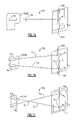
- FIG. 2 ais a perspective view of a first optical reader imaging module according to the invention.
- FIG. 2 bis side view of a first optical reader imaging module according to the invention.
- FIGS. 2 c and 2 dare perspective views of a second imaging module according to the invention.
- FIG. 2 eis an assembly view of a second imaging module according to the invention.
- FIGS. 3 a and 3 bare block electrical diagrams of optical readers according to the invention.
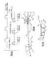
- FIG. 3 cis a timing diagram illustrating an exemplary method of controlling a laser diode assembly according to the invention.
- FIG. 4 ais a side view schematic diagram of one type of optical reader according to the invention.
- FIG. 4 bis a side view schematic diagram of a type of imaging module according to the invention.
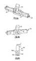
- FIGS. 5 a – 5 bare perspective views of a type of imaging module according to the invention.
- FIGS. 5 c – 5 dare perspective views of a type of imaging module according to the invention.
- FIGS. 6 a – 6 bare perspective view of an embodiment of an optical member according to the invention having aiming optics, including a prism.
- FIG. 6 cis a schematic view of a laser diode assembly
- FIGS. 7 a – 7 hillustrate schematic views of various long range aiming systems according to the invention.
- FIGS. 8 a – 8 bare schematic diagrams illustrating methods for assembly of an imaging module according to the invention.
- FIG. 9 ais a perspective view of an optical reader according to the invention.
- FIGS. 9 b – 9 care flow diagrams illustrating methods for controlling an optical reader according to the invention.
- FIG. 10is a side view of an optical reader according to the invention having a plurality of imager modules.
- Reader 5is adapted for reading at very long range reading distances e.g. such as five feet or more.
- reader 5is employed to read standard or “retro-reflective” bar codes. Retro-reflective bar codes, common in warehouse and factory applications, are formed on highly reflective surfaces such that a majority of incident light is reflected back to reader 5 .
- reader 5includes imaging optics 40 (as seen e.g. in FIGS. 2 b and 2 e ) which configure reader 5 so that reader 5 has a long range best-focus distance (e.g. more than 5 feet).
- long range reader 5typically includes a long range targeting assembly which is adapted so that a visible aiming pattern P (see FIGS. 7 a – 7 h ) is projected within or proximate a target, T, at a long reader-to-target distance.
- targetherein refers to the space on an indicia-bearing substrate, s, which is presently in a field of view of reader 5 .
- Indicia-bearing substrate, swhich bears a decodable character or symbol can be provided, for example by a piece of paper, an apparatus, an article of manufacture, a box, or a shipping container as is shown in the specific application view FIG. 1 .
- an optical readercan include preassembled imaging modules carrying various optical emit and receive components, which can be modularly installed inside a reader housing.
- a “preassembled” imaging moduleis typically assembled as a self-contained multicomponent part unit as shown in e.g. FIGS. 2 a – 2 e prior to being mounted in a reader housing. Long range reading imaging modules according to the invention are shown and described with reference to FIGS. 2 a – 2 e.
- Imaging module 10 , 10 - 1includes a support assembly 80 which receives and supports various reader components. Supported on support assembly 80 are an imaging assembly including a plural photodetector image sensor 32 and imaging optics 40 for focusing target indicia onto image sensor 32 .
- image sensor 32is provided by a 1D photodetector array incorporated on an integrated circuit chip.
- an imaging module according to the inventioncan also comprise a 2D image sensor.
- imaging optics 40are adapted so that reader 5 has a best focus receive optic distance of greater than 5 feet.
- imaging optics 40are adapted so that reader 5 has a best focus receive optic distance of 6.56 feet (2.0M).
- Imaging optics 40can include e.g. a single element lens, a two element lens (lens doublet) or three element lens (lens triplet).
- imaging optics 40are adapted so that reader 5 has a best focus receive distances of 10 feet, 20 feet, and 30 feet.
- Optics 40can comprise any suitable material e.g. glass or plastic. In the embodiment of FIGS.
- imaging optics 40are shown as being provided in an optical package known as a lens card. Optics 40 may also be packaged in an optical package known as a lens barrel as is shown in the embodiment of FIG. 2 e to be described herein.
- the imaging assemblycan include a vertical oriented slit aperture card 41 as explained in U.S. application Ser. No. 09/658,811, filed Sep. 11, 2000, entitled “Optical Assembly for Barcode Scanner,” incorporated herein by reference.
- module 10 - 1further includes an illumination assembly comprising at least one LED and at least one laser diode assembly for projecting a long range aiming pattern.
- the illumination system of module 10 - 1includes LEDs 18 , apertures 43 , and a lens member 26 .
- Lens member 26includes surfaces 27 formed on light entry surfaces of lens member 26 for horizontally spreading light from LEDs 18 and imaging lens surfaces 25 for imaging apertures 43 into target space, T.
- Alternative embodiments of illumination systemswhich may be incorporated in module 10 - 1 are described in U.S. Ser. No. 10/093,140, filed Mar. 7, 2002, entitled “Optical Reader Aiming Assembly Comprising Aperture,” incorporated herein by reference. It is understood that apertures 43 can be deleted from the illumination system so that imaging lens surface 25 images LEDs 18 directly into target space without imaging apertures 43 in target space. It is also understood that LEDs 18 can be deleted altogether or disabled if ambient light is sufficient.
- an illumination assembly of module 10 - 1may include a targeting system which is adapted to project a long range aiming pattern P onto a target T such that the long range aiming pattern P is visible at long range distances (e.g. beyond 5 feet).
- long range aiming pattern Pis normally more visible than a short range aiming pattern Ps, particularly at longer range reading distances.
- Configuring reader 5 so that a long range aiming pattern P is projected on or about an indicia to be readincreases the likelihood that a field of view of reader 5 coincides with a symbol or character to be read.
- emit optics e.g. 25it is useful to configure emit optics e.g. 25 so that a best focus emit distance of reader 5 , at which an image of aperture 43 is optimally focused on a target substrate is at least as long as the best focus receive distance. For example, if a best focus receive distance of reader 5 is 20 feet, reader 5 is advantageously adapted so that a best focus emit distance of reader 5 is at least 20 feet.
- Configuring reader 5 so that reader 5 has a best focus emit distance of at least as long as a best focus receive distanceincreases a strength of image information electronic signals output by image sensor 32 .
- the targeting system of module 10 - 1includes a laser diode assembly 60 of the type including a laser diode and collimating optics.
- Laser diode assembly 60may be e.g. a Model LM-761-A1 laser diode assembly of the type available from Excel Scientech Co. of Taiwan as is shown in FIG. 6 c .
- exemplary laser diode assembly 60includes a PCB 60 p supporting laser diode 60 d , and collimating optics 60 c housed within a diode assembly housing 60 h .
- laser diode assembly 60is disposed within protective holder 61 which houses assembly 60 .
- Protective holder 61 housing and supporting laser diode assembly 60is disposed in clips 65 of module 10 - 1 , the clips integrally formed on support assembly 80 .
- Clips 65support holder 61 and assembly 60 in a certain position relative to support assembly 80 .
- Imaging module 10 , 10 - 2 as shown in FIGS. 2 c , 2 d , and 2 eincludes a support assembly 80 having an image sensor containment section and an imaging optic retainer section 82 , a first circuit board 14 a carrying a plural photodetector image sensor 32 and aiming LEDs 18 , a second circuit board 14 b carrying illumination LEDs 16 , an optical member 26 carrying aiming and illumination optics 25 , 27 , and support posts 84 holding the various components of the module together.
- imaging module 10 - 2further includes laser diode assembly 60 , as described previously.
- Laser diode assembly 60 as in module 10 - 1may be installed in holder 61 , which in turn is disposed in clips 65 formed on assembly 80 . Disposing holder 61 in clips 65 securely positions assembly 60 in a certain position relative to support assembly 80 .
- Laser diode assembly 60 in any of the embodiments showncan be replaced with another light assembly suitable for producing a visible light pattern at long range reading distances.
- laser diode assembly 60can be replaced with a light assembly comprising an LED in combination with collimating optics for collimating light from the LED.
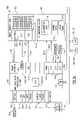
- FIGS. 3 a and 3 bElectrical block diagrams illustrating operations of electrical circuits for control of a long range reader according to the invention are now described with reference to FIGS. 3 a and 3 b .
- An electrical circuit 100 for controlling operation of a 2D long range imaging module e.g. module 10 - 2is described generally with reference to FIG. 3 a .
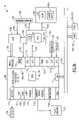
- An electrical circuit 101 for controlling operation of a 1D long range imaging module e.g. module 10 - 1is described generally with reference to FIG. 3 b.
- electrical circuit 100includes a control circuit 140 comprising CPU 141 , system RAM 142 and system ROM 143 and frame grabber block 148 .
- Electrical circuit 100further includes an image sensor 32 typically provided by a photosensitive array and an illumination block 160 having illumination LEDs 16 aiming LEDs 18 and laser diode 60 d of a laser diode assembly 60 as shown in the physical form view of FIGS. 2 c – 2 e .
- Image sensor 32 of FIG. 3 ais shown as being provided by a 2D photo diode array. If image sensor 32 is replaced by a 1D image sensor, then aiming LEDs 18 and illumination LEDs 16 may be constituted by one set of LEDs.
- image sensor 32 incorporated in an image sensor IC chip 182typically further includes an image sensor electrical circuit block 134 .
- Image sensor electrical block 134includes control circuit 135 for controlling image sensor 32 , and A/D conversion circuit 136 , for converting analog signals received from image sensor into digital form and integrated clock 137 sometimes referred to as an oscillator.
- multifunctional IC chip 180which in addition to including CPU 141 includes numerous other integrated hardware components.
- multifunctional IC chip 180may include a display control block 106 , several general purpose I/O ports 116 , several interface blocks such as a USB circuit block 107 and UART block 108 for facilitating RS 232 communications, a UART block 109 for facilitating Irda communications, and a pulse width modulation (PWM) output block 114 .
- Multifunctional processor IC chip 180can also have other interfaces such as a PCMCIA interface 111 , a compact flash interface 112 , and a multimedia interface 113 .
- Multifunctional processor IC chip 180may be one of an available type of multifunctional IC processor chips which are presently available such as a Dragonball IC processor chip available from Motorola, an Anaconda IC processor chip available from Motorola, a DSC IC chip of the type available from Texas Instruments or a multifunction IC Processor chip of a variety available from Clarity, Inc.
- Frame grabber block 148 of IC chip 180replaces the function of a frame grabbing field programmable gate array (FPGA) as discussed in commonly assigned application Ser. No. 09/954,081, (now U.S. Pat. No. 6,561,428) filed Sept. 17, 2001, entitled “Imaging Device Having Indicia-Controlled Image Parsing Mode,” incorporated herein by reference and application Ser. No. 09/904,697, (now U.S. Pat. No. 6,722,569) filed Jul. 13, 2001, entitled “An Optical Reader Having a Color Imager” incorporated herein by reference.
- FPGAfield programmable gate array
- frame grabber block 148is specifically adapted collection of hardware elements programmed to carry out, at video rates or higher, the process of receiving digitized image data from image sensor chip 182 and writing digitized image data to system RAM 142 which in the embodiment shown is provided on a discrete IC chip.
- Frame grabber block 148includes hardware elements preconfigured to facilitate image frame capture.
- Frame grabber block 148can be programmed by a user to capture images according to a user's system design requirements.
- Programming options for programming frame grabber block 148include options enabling block 148 to be customized to facilitate frame capture that varies in accordance with image sensor characteristics such as image sensor resolution, clockout rating, and fabrication technology (e.g. CCD, CMOS, CID), dimension (1D or 2D) and color (monochrome or color).
- Line 151represents one or more physical communication lines.
- I 2 C interface 115 of chip 180is utilized to facilitate communication with chip 182 (if another image sensor chip is selected another type of interface e.g. interface 116 may be utilized).
- Other types of signalsmay be sent over line 151 during the course of image capture.
- Line 151may carry, for example, timing initialization, gain setting and exposure setting signals.
- control block 135 of image sensor chip 182When control block 135 of image sensor chip 182 receives an image capture enable instruction, control block 135 sends various signals to frame grabber block 148 .
- Image sensor control block 135typically sends various types of synchronization signals to frame grabber block 148 during the course of capturing frames of image data.
- control block 135may send to frame grabber block 148 “start of frame signals” which inform frame grabber block 148 that chip 182 is ready to transmit a new frame of image data, “data valid window” signals which indicate periods in which a row of image data is valid and “data acquisition clock” signals as established by clock 137 controlling the timing of image data capture operations.
- line 152represents three physical communication lines, each carrying one of the above types of signals.
- vertical and horizontal synchronization signalsare processed by frame grabber 148 to internally generate a data valid window signal.
- Frame grabber block 148appropriately responds to the respective synchronization signals, by establishing buffer memory locations within integrated RAM 149 of block 148 for temporary storage of the image data received from image sensor chip 182 over data line 159 .
- buffer RAM 149 of frame grabber block 148may store a partial (e.g about 0.1 to 0.8) or a full line of image data.
- circuit 100includes a system bus 150 .
- Bus 150may be in communication with CPU 141 via a memory interface such as ELM interface 117 of IC chip 180 .
- System RAM 142 and system ROM 143are also connected to bus 150 and in communication with CPU 141 via bus 150 .
- RAM 142 and ROM 143are provided by discrete IC chips. System RAM 142 and system ROM 143 could also be incorporated into processor chip 180 .
- electrical circuit 100may include one or more long term storage devices.
- Electrical circuit 100can include for example a “flash” memory device 120 .
- flash memory devicesinclude Several standardized formats are available for such flash memory devices including: “Multimedia” (MMC), “Smart Media,” “Compact Flash,” and “Memory Stick.” Flash memory devices are conveniently available in card structures which can be interfaced to CPU 141 via an appropriate “slot” electromechanical interface in communication with IC chip 180 . Flash memory devices are particularly useful when reader 5 must archive numerous frames of image data.
- Electrical circuit 100can also include other types of long term storage such as a hard drive which may be interfaced to bus 150 or to an appropriate I/O interface of processor IC chip 180 .
- control circuit 140is configured to control the turning off and turning on of LEDs 16 , 18 and laser diode 60 d of illumination block 160 .
- Control circuit 140preferably controls illumination block 160 in a manner that is coordinated with the capturing of the frames of image data.
- Illumination LEDs 16are typically on during at least a portion of frame capture periods. Configuring circuit 140 so that LEDs 16 , 18 , and diode 60 d have off periods significantly reduces the power consumption of circuit 100 .
- electrical circuit 100can be configured so that PWM output interface 114 of IC chip 180 controls illumination LEDs of an imaging module such as illumination LEDs 16 of module 10 - 2 .
- illumination block 160is in communication with PWM output interface 114 and configured in such manner that LEDs 16 are turned on at a leading edge of PWM pulses output at PWM interface 114 , and are turned off at falling edges of PWM pulses output at PWM interface 114 .
- PWM interface 114should be configured so that several pulses are generated and sent over communication line 153 i during the time that a single row of pixels of image data are exposed to light prior to clocking out of pixel values corresponding to that row.
- illumination LEDs 16would be turned on and off several times during the exposure period for exposing a row of pixels to light.
- the number of pulses output by PWM output 114 during the time that a single row of pixels are exposedshould not vary substantially from row to row.
- the pixel clock signal received at frame grabber block 148 of IC chip 180can be utilized to generate the PWM output. It can be seen, therefore, that multifunctional IC chip 180 including frame grabber block 148 and PWM output 114 greatly simplifies the task of developing PWM signals for use in controlling illumination LEDs 16 of module 10 .
- PWM output 114 and illumination block 160are configured so that PWM output 114 controls the intensity of illumination, not the on time/off time of illumination.
- LEDs block 160 in such an embodimentcan include a power supply circuit which is interfaced to PWM output 114 such that the PWM signal output at PWM output 114 varies the voltage or current supplied to LEDs 16 .
- aiming LEDs 18 of circuit 100can be controlled by a signal transmitted by a general purpose I/O port 116 of IC chip 180 over communication line 153 a .
- Multifunctional processor IC chip 180can be programmed so that an aiming LED control signal controlling LEDs 18 is driven to an ON state when pixels of image sensor 32 are not being exposed to light.
- Such control of image sensor 32alleviates any affect which aiming LEDs 18 would otherwise have on an image signal generated by image sensor 32 .
- image sensor 32should be selected to be of a type wherein all rows of image sensor 32 are exposed simultaneously, or else should otherwise be controlled so that periods exist wherein no row of image sensor 32 is exposed to light.
- a short range aiming pattern, P s(see FIG. 9 a ), as projected by aiming LEDs 18 is highly visible to a user only where reader 5 is in a short range reading distance (e.g. less than 36′′ from a target).
- Long range aiming pattern P as projected by laser diode assembly 60is normally highly visible to user over all reading distances.
- one or both of aiming LEDs 18 and targeting diode 60 dcan be selectively disabled in a manner depending on reading conditions, e.g. decoding delay time, reader-to-target distance.
- Electrical circuit 101controls operation of a single imaging module optical reader comprising a low cost 1D CCD image sensor 32 disposed on an IC chip 182 .
- Image sensor 32 of FIG. 3 bmay be provided for example in a Toshiba Model TCD 1304 AP linear image sensor. Further aspects of an exemplary 1D imaging module are described, for example, in application Ser. No. 09/658,811, filed Sep. 11, 2000, entitled “Optical Assembly for Barcode Scanner,” incorporated herein by reference.
- electrical circuit 101includes a control circuit 140 which, like control circuit 140 of circuit 100 is partially incorporated in a multifunctional processor IC chip 180 including CPU 141 and a frame grabber block 148 .
- Control circuit 140 of circuit 101further includes system RAM 142 , system ROM 143 and supplementary central processor unit (CPU) 141 , integrated on processor IC chip 179 .
- System RAM 142 and system RAM 143are in communication with EIM interface 117 of IC chip 180 via bus 150 .
- Processor IC chip 179provides control and timing operations similar to that provided by electrical block 134 of image sensor chip 182 described in FIG. 3 a .
- Processor IC chip 179in general, sends synchronization signals and digital clocking signals to IC chip 180 , and sends digital clocking signals to A/D 136 and 1D image sensor chip 182 including image sensor 32 .
- Processor IC chip 179 of circuit 101may be a relatively low power processor IC chip such as an 8 BIT Cyprus PSOC CY8C26233-24PVI Microcontroller processor IC chip.
- processor IC chip 179When trigger 13 t is pulled, CPU 141 transmits an image capture enable instruction over communication line 151 .
- processor IC chip 179In response to receipt of an image capture enable instruction received from chip 180 , processor IC chip 179 performs a variety of operations. Via communication line 152 , processor IC chip 179 may send synchronization signals, such as “start of scan,” “data valid window,” and “data acquisition clock” signals to frame grabber block 148 .
- Processor IC chip 179may also send timing signals and digital clocking signals (e.g. master clock, integration clear gate, and shift gate pulse) to 1D image sensor chip 182 including 1D image sensor 32 .
- Processor IC chip 179typically also transmits a master clock signal to A/D block 136 .
- CPU 141 of chip 180may also send e.g. gain setting, exposure setting, and timing initialization signals via line 151 to IC chip 179 .
- Communication between IC chip 180 and IC chip 179may be made via an SPI interface or I/O interface 116 of chip 180 and chip 179 .
- Processor IC chip 179may be replaced by a programmable logic circuit, e.g. a PLD, CPLD, or an FPGA. IC chip 179 could also be replaced by an ASIC.
- analog voltage levels transmitted by image sensor 32 on line 155are converted into gray scale pixel values by A/D converter 136 and then transmitted via line 159 to frame grabber block 148 .
- Circuit 101could also include a what may be referred to as an analog digitizer which processes an analog signal generated by image sensor 32 to generate a two-state output signal that changes state in accordance with light-to-dark and dark-to-light transitions of the image sensor analog output signal.
- Illumination block 160 of a 1D long range image sensor reader 5 as explained with reference to FIGS. 2 a and 2 btypically includes a single bank of LEDs 18 which simultaneously illuminates a target area and projects a short range aiming pattern (P s ) facilitating aligning of the reader with a target indicia, and laser diode 60 d of laser diode assembly 60 .
- LEDs 18 of 1D imaging module 10 - 1 like LEDs 16 , 18 of module 10 - 2can be pulsed so as to reduce energy consumption by LEDs 18 .
- Laser diode 60 dcan be controlled so as to be selectively turned on intermediate of frame exposure periods in the manner described with reference to the timing diagram FIG. 3 c .
- a laser diode control signal 168can be selectively turned ON intermediate of frame (which comprise 1 or a limited number of rows of pixels in the case of a 1D image sensor), exposure periods P 1 , P 2 , P 3 to the end that light from laser diode assembly does not affect an image signal generated by image sensor 32 .
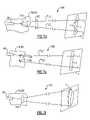
- a laser diode assembly 60is canted such that an axis a E of an emitted laser beam emitted by laser diode assembly 60 is at an angle with respect to imaging axis a i to the end that a spot of light P, is projected at a horizontal centerline 400 of a field of view of reader 5 at one specific reader distance, d.
- the position of aiming pattern P with respect to a horizontal centerline 400 of a field of view of reader 5will change depending on the reader-to-target distance.
- module 15At close reader distances 70 , module 15 will project an aiming pattern P above a horizontal centerline 400 of a field of view. At longer reader distances 71 , pattern P will be projected below a centerline 400 .
- Module 10 - 1 as shown in FIGS. 2 a and 2 bis adapted so that a spot of light aiming pattern P projected by targeting system 60 remains at approximately the same position with respect to a centerline 400 of a field of view at all reader to target distances.
- Module 10 - 2 shown in FIGS. 2 c – 2 eis devoid of light redirecting elements for redirecting laser beam light emanating from laser diode assembly 60 .
- Module 10 - 1on the other hand includes a prism 62 for redirecting aiming laser beam light emanating from laser diode assembly 60 . As best seen in seen in FIG.
- prism 62reduces the y-direction spacing between an emit axis a E corresponding to the path of emitted laser beam aiming light and an imaging axis a i of module 10 - 1 . Reducing the y-direction spacing between emit axis a E and imaging axis a i results in the position of aiming pattern P being moved closer to a horizontal centerline 400 of a reader field of view.
- Prism 62could be replaced by alternative light redirecting elements such as mirrors or a combination of mirrors and prisms.
- Prism 62can be integrally formed on optical member 26 so that optical member 26 is a one piece unit comprising prism 62 , at least one emit optical element 25 and at least one diffuser optical element 27 .
- module 10 - 1includes emit optic light folding elements (e.g. optics that fold light emitted from laser diode assembly 60 ), it may also be desirable to configure reader 5 so that reader 5 includes receive optic light folding elements.
- Module 10 - 4 of FIG. 4 bincludes mirrors 39 disposed in a receive optical path for folding imaging axis a l of module 10 - 4 . Incorporating light folding optical elements in module 10 - 4 can reduce z-direction (length) space consumption requirements of module 10 - 4 , rendering module 10 - 4 more readily fittable into optical reader housings having limited available space for accommodation of module 10 - 4 .
- Mirrors 39 of module 10 - 4can be replaced by a prism, prisms, or combination of mirrors and prisms.
- the desirability of incorporating light folding elements in an optical receive path of a long range reader moduleincreases as the best focus receive distance of module 10 increases maintaining the characteristics of imaging optics 40 constant.
- the best focus distance of module 10in general can be increased by increasing a focal length of optics 40 together with a distance between imaging optics 40 and image sensor 32 .
- a spacing between imaging optics 40 and image sensor 32can be achieved without increasing the overall z-direction space consumption of module 10 .
- top surface 64 of support assembly 80includes support members 86 extending upwardly therefrom.
- Support members 86may be integrally formed on, bolted to, adhesively bonded to or otherwise securely attached to top surface 64 of assembly 80 .
- Laser diode assembly 60 of module 10 - 4is disposed within box housing 61 having sidewalls 61 s .
- Sidewalls 61 s of holder 61 and upwardly extending support members 86have pin-receiving holes 87 formed therein.
- a resilient pad 89is first installed in the holder receiving area of top surface 64 defined by support members 86 .
- Resilient pad 89may be secured on top surface 64 with use of adhesive. With resilient pad 89 located on top surface 64 , holder 61 including diode assembly 60 is disposed within a holder-receiving area of module 10 - 5 defined by support members 86 . Holder 61 is positioned on module 10 - 5 so that pin-receiving holes 87 of holder 61 (not shown) and support member 87 are aligned. With pin holes of holder 61 and support members 86 aligned, pins 88 are inserted into the aligned pin receiving holes 87 .
- Holder 61pivots about an axis a p defined by pins 88 when pins 88 are installed in the aligned pin holes of holder 61 and support members 86 . Pivoting holder 61 about axis a p adjusts an angle defined between emit axis a E and imaging axis a l . For securing laser diode assembly 60 at a precisely defined angular position relative to imaging axis a l , adjustment screw 90 fittable in holes of holder 61 and surface 64 is adjusted. For adjusting an angle between emit axis a E and imaging axis a l , adjustment screw 90 is adjusted. As best seen in FIGS.
- imaging module 10 - 5includes a one piece optical member 26 having emit optic surface 25 , for imaging an aperture 43 over a target, T, a negative lens surface 27 , and integrated prism 62 .
- One-piece member 26further includes a window 29 disposed about imaging axis a l for allowing imaging light rays to pass there-through.
- Module 10 - 5 of FIGS. 5 a and 5 bmay also include a spring 90 s fitted over screw 90 and interposed between holder 61 and surface 64 .
- Spring 90 swhich biases holder 61 away from surface 64 , may supplement or replace a biasing function provided by resilient pad 89 .
- FIGS. 5 c and 5 dAdditional finely adjustably laser diode assembly mounting assemblies are described with reference to FIGS. 5 c and 5 d .
- a bottom bed 94 of module 10 - 6is disposed on top surface 64 of assembly 80
- cylindrical holder 61is placed on top of bed 94
- top clamp 95is disposed over cylindrical holder 61 .
- Bottom bed 94 and top clamp 95have contours to allow pivotal rotation of holder 61 within the clamping assembly defined by bed 94 and top clamp 95 .
- a clamping screw 91is disposed through aligned screw-accommodating holes of top clamp 95 , holder 61 and bed 94 , and then tightened to secure holder 61 in a desired position.
- Screw holes of holder 61should be elongated about a circumference of holder 61 to accommodate pivoting of holder 61 .
- module 10 - 7is constructed substantially the same as module 10 - 6 except that module 10 - 7 is adapted to allow rotational fine adjustment of holder 61 within a clamping assembly defined by top clamp 95 and bottom bed 94 instead of pivotal adjustment about a pivoting axis a p as in module 10 - 6 .
- holder 61is ball shaped and complementary contours of top clamp 95 and bottom bed 94 are spherical so as to accommodate ball-shaped holder 61 .
- screws 91are inserted into aligned holes 96 of clamp 95 and bed 94 and then tightened to secure holder 61 in a desired position.
- a imaging module 10 - 5 having finely adjustable targeting opticsis disposed in a fixture 810 which securely holds module 10 in a fixed position.
- a test target substrate, s(which may be provided by a wall) is disposed at a certain expected long range reading position (e.g. 5 feet, 10 feet, 20 feet, 30 feet) within the field of view of module 10 .
- Printed matter 820 , 822may be formed on test substrate, s, for aiding the adjustment of laser diode assembly 60 .
- Printed matter 820may be an outline of the expected field of view of module 10 on substrate s.
- Printed matter 820may be a small-height linear bar code adapted so that reading of the bar code included in printed matter 820 indicates that a field of view of module 10 coincides with printed matter 820 .
- Printed matter 822may be a marking for indicating the desired position of an aiming pattern P on test substrate s relative to the expected field of view.
- screw 90(with reference to module 10 - 5 ) is loosened and or tightened until the beam projected aiming pattern coincides with printed matter marking 822 .
- laser diode assembly 60can be advantageously turned on intermediate frame exposure period and turned off during frame exposure periods.
- laser diode 60 d of laser diode assembly 60is turned on during frame exposure periods so that aiming pattern P if included in a field of view of module 10 - 5 will be represented in a captured image captured via actuation of module 10 .
- module 10 - 5is provided in electrical communication with video monitor 68 d (here provided by a personal computer assembly) and monitor 68 d and module 10 - 5 are configured so that monitor 68 d electronically displays an electronic representation 830 of a captured frame of image data.
- module 10includes a 2D image sensor representation 830 can be a 2 d image representation.
- representation 830can be an enhanced height visual representation, as is shown in the embodiment of FIG. 8 b .
- Representation 830can also be a false color representation.
- aiming pattern Pmay not be visible in a captured 1 ⁇ N “slice” frame of image data if emit axis a E and imaging axis a l are substantially spaced and in parallel relation. However, at longer reading distances, beam projected aiming pattern P will be represented within a slice frame of image data. In the adjustment system described with reference to FIG.
- fixture disposed module 10 - 5 and substrate sare spaced apart at such distance so that when an aiming beam traveling along axis a E is parallel with imaging axis a i , aiming pattern P projected on substrate s by laser diode assembly 60 is detectable within a captured frame of image data but is not detectable if an angle between emit axis a E and imaging axis a l is incorrect.
- set screw 90can be gradually loosened from a tight position until aiming pattern P first becomes visible within electronically displayed representation (as indicated by aiming pattern representations P R of FIG. 8 b ), or electronically detectable within a frame. When such a feedback is achieved, the position of laser diode assembly 60 can be considered to be finely adjusted.
- a representation P R of pattern Pis included in displayed representation 830 of a captured frame of image data.
- the printed matter feed back system of FIG. 8 a and electronically displayed feedback system of FIG. 8 bcan be combined in a variety of useful ways.
- the printed matter 820 , 822 of FIG. 8 acan be formed on test target substrate s of FIG. 8 b and can be captured and electronically displayed on a monitor 68 d as in the system of FIG. 8 b .
- a usercan adjust the position of aiming pattern P to coincide with printed matter marking 822 while observing electronic display 68 d to confirm that printed matter 822 is actually being captured by module 10 .
- Module 10 of fine adjustment visual feedback systems of FIGS. 8 a and 8 bcan include one fine adjustment mounting assemblies, e.g. one of the assemblies of modules 10 - 5 , 10 - 6 , 10 - 7 described with reference to FIGS. 5 a – 5 e.
- FIGS. 7 a – 7 hshowing top perspective schematic views of alternative imaging modules projecting various aiming patterns onto a target substrate, s, a variety of additional alternative embodiments of the invention for projecting multiple spot aiming patterns P are described.
- a long range aiming patterncomprising a pair of aiming spots, P 1 and P 2 , if projected on a line parallel with a horizontal centerline 400 of a field of view of imaging module 10 aid in the X-Y plane rotational alignment of module 10 with respect to a target indicia, i.
- FIG. 7 aa schematic block diagram corresponding to modules 10 - 1 , 10 - 3 , 10 - 4 , and 10 - 5 previously described having a single laser diode assembly 60 projecting a single spot aiming pattern P is shown in FIG. 7 a .
- laser diode assembly 60 mounted on module 10projects a single spot aiming pattern P onto a target substrate P.
- the spot Pis projected slightly above a horizontal centerline 400 of a field of view of module 10 delimited by target, T.
- System 701includes an optional prism 62 as described previously which affects the vertical axis positioning of pattern P.
- a pair of laser diode assemblies 60 mounted on module 10project an aiming pattern P comprising two spots P 1 and P 2 on a target substrate, s.
- Diode assemblies 60are arranged so that emit axes a E1 and a E2 of the two diode assemblies are in diverging relation. Configured in such manner, aiming spots P 1 and P 2 of aiming pattern P are substantially spaced apart at expected reading distances.
- a pair of laser diode assemblies 60are also mounted to module support assembly 80 in system 703 depicted in FIG. 7 c .
- diode assemblies 60are disposed in converging relation with so that apex, x, is defined at reading distances less than expected reading distances to the end that imaging axes a E1 and a E1 are in diverging relation at expected reading distances.
- System 703 like system 702is configured so that spots P 1 and P 2 of aiming pattern P are substantially spaced apart at expected reading distances.
- Module 10 in system 703is a 2D imaging module having a rectangular field of view corresponding to a target, T, as opposed to slice field of view corresponding to slice targets, T, depicted in systems 701 and 702 .
- a single laser diode assembly 60is disposed on module support assembly 80 together with prism 62 .
- Prism 710is shaped and disposed so that a light beam entering prism 710 is split to generate two exit beams traveling along beam axes a E1 and a E2 .
- System 704like system 702 and system 703 is configured so that expected reading distances, spots P1 and P2 of aiming pattern P are in diverging relation.
- a physical form view of system 704is provided by FIGS. 5 c and 5 d , showing perspective views of module 10 - 6 and module 10 - 7 , respectively. Shown as being an apex-out type prism, prism 710 could be provided by an apex-in type prism.
- a single laser diode assembly 60is mounted on support assembly 80 in combination with beam splitter 720 and mirror 730 .
- a part of a light entry beam entering splitter 720is transmitted through splitter 720 while a part of a light entry beam entering splitter 720 is directed to mirror 730 which directs the light beam to target substrate, s.
- System 705is configured so that beams traveling along axes a E1 and a E2 are in diverging relation to the end that spots P 1 and P 2 of aiming pattern P are substantially spaced apart at expected reading distances.
- a single laser diode assembly 60is mounted on support assembly 80 together with a shaping optic 740 .
- Shaping optic 740shapes a laser light beam emanating from laser diode assembly 60 into an elliptical aiming pattern P which is visible at expected reading distances.
- Shaping optic 740may be provided, for example, by a cylindrical lens.
- a single laser diode assembly 60is mounted on support assembly 80 together with a first mirror 744 and a second mirror 746 having a diffractive element 748 formed thereon.
- Diffractive element 748scatters a light beam directed thereto into three discrete light beams each traveling along one of emit axes a E1 , a E2 , a E3 .
- System 707is configured so that beams having axes a E1 , a E2 , and a E3 are in diverging relation to the end that spots P 1 , P 2 , and P 3 of pattern P are substantially spaced apart at expected reading distances.
- Diffractive element 748could in another embodiment be spaced apart from mirror 746 .
- a single laser diode assembly 60is mounted on support assembly 80 together with a moving mirror 750 .
- Moving mirror 750is moved to sweep a laser beam across a target substrate within a field of view of image sensor 32 delimited by target area T as depicted by FIG. 7 h .
- Aiming pattern P in the embodiment of FIG. 7 happears as a straight thin line to a user.
- Moving mirror 750may be pivoted or vibrated.
- Moving mirror 750can be fabricated utilizing Micro-Electro-Mechanical Systems (MEMS) technology to the end that moving mirror 750 includes micromachined parts incorporated on an IC chip, wherein movement of the moving mirror 750 is responsive to a signal sent to the MEMS IC chip from control circuit 140 .
- System 708can further include a single photodetector 760 configured to sense light from scanned light beam as is reflected from substrate s so that laser diode assembly 60 in combination with moving mirror 750 in combination with photodetector 760 form the components of a laser scan engine. Signals generated by photodetector 760 can be digitized or subjected to analog-to-digital conversion and transmitted to control circuit 140 .
- Control circuit 140can subject the received signals to decoding so as to provide a secondary decoded output message that supplements a decoded out message generated as described previously by subjecting a frame captured via actuation of image sensor 32 to decoding.
- FIGS. 9 a – 9 cSpecific methods for operating long range reader 5 are described with reference to FIGS. 9 a – 9 c .
- a long range reader 5 having a display 13 dis shown which is adapted to be operated in three operating modes: (1) a “laser aimer enabled” mode corresponding to displayed message 910 ; (2) a “laser aimer disabled” mode corresponding to displayed message 912 ; and (3) an “adaptive laser aimer” mode corresponding to displayed message 914 .
- These three modescan be actuated via selection of the appropriate key of key board 13 k or other known GUI highlighting or pointer based selection method.
- reader 5does not include a display 13 d and keyboard 13 k or if another menu interface is desired, the selection of a desired menu option can be made by reading an appropriate “menu symbol” as described in U.S. Pat. No. 5,929,418, entitled “Optical Reader Having Improved Menuing Features” incorporated by reference or by transmission of a command from a host computer such as a PC which is in communication with reader 5 .
- a host computersuch as a PC which is in communication with reader 5 .
- long range aiming pattern Pis highly useful in aiding the alignment of reader 5
- long range aiming pattern Pmay not be necessary in certain circumstances. For example, at short range reading distances as depicted in FIG.
- a readercan be adequately aligned with use of short range LED projected aiming pattern Ps projected by aiming/illumination LEDs 18 of a 1D imaging module or aiming LEDs 18 of 2D imaging module as described herein. If long range aiming pattern P is not necessary for aiding the alignment of reader 5 it may be desirable to disable laser diode assembly 60 for purposes of reducing energy consumption.
- laser diode assembly 60is always enabled until the mode is changed. That is, every time trigger 13 t is pulled, laser diode 60 d is actuated at least during periods intermediate of frame exposure periods.
- laser aimer disabledis selected, aimer laser diode assembly 60 is disabled until a mode is changed. That is, laser diode 60 d is never actuated even when trigger 13 t is pulled, until a mode is changed.
- laser diode assembly 60is adaptively enabled or disabled depending on a sensed reader condition.
- control circuit 140determines if a trigger 13 t has been pulled. If trigger 13 t has been pulled, control circuit 140 proceeds to block 932 to capture a frame of image data, and then to block 934 to subject the frame of image data to a decode attempt.
- the attempt to decode decodable indiciamay be made in accordance with one of a decoding methods that is described in U.S. application Ser. No. 09/904,697, filed Jul. 13, 2001, entitled “Optical Reader Having a Color Imager,” incorporated herein by reference.
- controller 140 at block 936determines that decoding was successful, control circuit 140 at block 938 outputs the decoded message. If decoding was not successful, control circuit 140 proceeds to block 940 to evaluate whether a delay threshold has been satisfied by reader 5 .
- the current delay of reader 5may be calculated based on the real time elapse accruing from the time that trigger 13 t is first pulled (block 930 ) utilizing a real time clock function of IC chip 180 .
- the delay conditioncan also be calculated, for example, based on the number of frames that have been captured since the time that trigger 13 t was pulled or by another suitable method. If the delay threshold has been satisfied, control circuit 140 proceeds to block 944 to enable laser diode 60 d from a normally disabled state.
- Block 942indicates that control circuit 140 does not have to repeatedly re-enable diode assembly 60 after enabling assembly 60 a first time.
- the inventiontherefore, includes an optical reader comprising an imaging assembly having a plural photodetector image sensor and an imaging axis; an illumination assembly comprising at least one illumination LED and at least one laser diode assembly, wherein said laser diode assembly is adapted to project a long range aiming pattern onto a target substrate; a control circuit in communication with said imaging assembly and said illumination assembly, wherein said reader has an adaptive laser aimer operating mode wherein said control circuit, in response to receipt of a trigger signal calculates a delay; and enables said laser diode assembly if said delay is equal to or greater than a threshold delay.
- Incorporating the method of FIG. 9 b into reader 5configures reader 5 so that long range aiming pattern P is projected onto a target substrate, s, only after a delay threshold has been satisfied. In some reading applications, reading may be so readily accomplished that long range aiming pattern P may not be needed for aiming reader 5 .
- laser diode assembly 60is adaptively enabled only under difficult reading conditions (which may be long range reading conditions) wherein reading is not successful within a predetermined time delay threshold.
- control circuit 140determines whether a reader-to-target distance threshold has been satisfied rather that determining whether a delay threshold has been satisfied as in block 940 ( FIG. 9 b ). If control circuit 140 at block 950 determines that reader 5 is at least as far from a target as a predetermined threshold distance, control circuit 140 proceeds to block 952 to enable laser diode assembly 60 .
- control circuit 140may pulse diode “on” intermediate of frame exposure periods as described herein. If control circuit 140 determines that a current reader-to-target distance is less than a threshold distance, then control circuit 140 proceeds to block 954 to disable aimer laser diode assembly 60 .
- Control circuit 140may calculate a current reader-to-target distance in a number of different ways.
- a method for generating a “degree of focus” signal which is indicative of reader-to-target distanceis described in U.S. Pat. No. 5,773,810, issued Jun. 20, 1998, entitled “Method for Generating Real Time Degree of Focus Signal for Handheld Imaging Device,” incorporated herein by reference.
- a reader-to-target distancecan be normally estimated based on the spacing between representations of aiming spots P 1 , P 2 in a captured image. It has been described herein that it is normally desirable to control laser diode 60 d to be OFF during frame exposure periods.
- an “enable laser diode assembly instruction(block 944 , block 952 ) can be coupled with a “disable LED illumination” instruction, which is executed by control circuit 140 to disable LEDs of module 10 such as LEDs 18 of 1D module 10 - 1 and either or both of illumination and aiming LEDs 16 , 18 of 2D module 10 - 2 ( FIG. 2 e ). At long range reading applications light from LEDs may be unnecessary, as explained herein, particularly under high ambient light conditions. It will be seen that “disable laser diode assembly” of block 954 , FIG. 9 c , can similarly be combined with an “enable LED” instruction.
- a plurality of imaging modules 10can be incorporated in reader 5 .
- Various designed for plural imaging module readers and electrical circuits for operating such readersare described in U.S. application Ser. No. 10/161,950 filed Jun. 4, 2002, entitled “Optical Reader Having a Plurality of Imaging Modules,” incorporated herein by reference.
- long range reader 5includes a pair of stacked imaging modules 10 a and 10 b and a laser diode based targeting system including laser diode assembly 60 which in the specific embodiment shown is not attached to either of module 10 a or module 10 b .
- Assembly 60can also be mounted to module 10 a and/or 10 b as described with reference to FIGS. 2 a – 2 e ).
- Lower and first imaging module 10 ais adapted for short range reading and is configured to have a best focus receive distance of less than 1 foot.
- Upper and second imaging module 10 bis adapted for long range reading and includes a best focus receive distance of about 5 feet (or alternatively, e.g. 10 feet, 20 feet, and 30 feet).
- Plural imaging module reader 5 as shown in FIG. 10may be operated in accordance with the flow diagrams as explained in FIGS. 9 b and 9 c , with a modification in that all frames of image data captured when laser diode assembly 60 is disabled are captured via an actuation of an image sensor of short range module 10 a and all frames captured when assembly 60 is enabled are captured via actuation of an image sensor of long range module 10 b.
- both of modules 10 a and 10 bare 1D modules as described e.g. with reference to FIGS. 2 a , 2 b , 5 a , 5 b , 5 c , and 5 d .
- both modules 10 a and 10 bare 2D imaging modules as described e.g. in relation to FIGS. 2 c – 2 e .
- one of modules 10 a or 10 bis a 1D imaging module and another of modules 10 a or 10 b is a 2D imaging module.
Landscapes
- Physics & Mathematics (AREA)
- Engineering & Computer Science (AREA)
- Electromagnetism (AREA)
- Health & Medical Sciences (AREA)
- General Health & Medical Sciences (AREA)
- Toxicology (AREA)
- Artificial Intelligence (AREA)
- Computer Vision & Pattern Recognition (AREA)
- General Physics & Mathematics (AREA)
- Theoretical Computer Science (AREA)
- Facsimile Scanning Arrangements (AREA)
- Image Input (AREA)
Abstract
Description
This application claims the priority, under 35 U.S.C. § 119(e), of U.S. Provisional Application Ser. No. 60/387,842 filed Jun. 11, 2002, entitled “Long Range Optical Reader”, which is incorporated herein by reference.
The invention relates to optical readers in general and particularly to optical readers adapted for long range reading of decodable indicia.
Bar codes and other decodable indicia are finding increased use including in industrial applications wherein bar codes are to be read at long range reading distances such as beyond five feet. Presently available optical readers configured for such long range reading are laser scan engine based. In a laser scan engine based optical reader, a laser beam is swept across a target substrate by a delicately mounted moving mirror.
Unfortunately, problems have been noted with presently available laser scan engine based long range optical readers. At long range reading distances, scanning lines projected by a laser scan engine are difficult to read, making it difficult to locate a decodable indicia within a field of view of the reader. Furthermore, laser scan engine based readers are susceptible to breakdown. If a laser scan engine reader is dropped, the delicately mounted scanning mirror can easily become misaligned. The need for ruggedized bar code readers, which can withstand drops and other incidents of high impact is especially great in industrial applications wherein long range reading is often required.
There is a need for an optical reader including a targeting system which enables a reader to be readily aligned with a target indicia even at long range reading distances.
According to its major aspects and broadly stated, the invention is a long range image sensor based optical reader.
In one aspect of the invention, in one embodiment, an optical reader includes an imaging module having a support assembly carrying an image sensor and imaging optics, wherein the imaging optics are selected so that a best receive optic focus position of the reader is at a long range such as more than about five feet.
In another aspect of the invention, in one embodiment, the reader includes a targeting system so that the target indicia can readily be spotted at long range reading distances. The targeting system can comprise a laser diode assembly of the type comprising a laser diode and collimating optics. The targeting system can further include folding optics such as mirrors or prisms which redirect the light emanating from the laser diode assembly so that the targeting beam is directed along a path substantially parallel to and proximate an imaging axis. The targeting system can be incorporated in an imaging module mounted in a reader housing. In one specific embodiment precision mounting assembly for precision mounting of a laser diode assembly is disposed on a support assembly of a reader imaging module.
In a further aspect of the invention, the reader's illumination system can be adapted so that a signal strength of image signals generated at long range reading distances is enhanced. A signal strength (signal to noise ratio) of a long range reader can be enhanced by configuring the reader to have a best emit focus distance longer than a best receive optic focus distance.
In another aspect of the invention, an imaging assembly of a reader of the invention can include moving optics which allow adjustment of the best receive focus position of the reader, or a second complete imaging system adapted for reading at shorter reading distances.
These and other details and advantages will become apparent from the detailed description of the preferred embodiment hereinbelow.
For a further understanding of these and objects of the invention, reference will be made to the following detailed description of the invention which is to be read in connection with the accompanying drawing, wherein:
An optical reader of the invention in use in an industrial application is shown inFIG. 1 .Reader 5 is adapted for reading at very long range reading distances e.g. such as five feet or more. Typically,reader 5 is employed to read standard or “retro-reflective” bar codes. Retro-reflective bar codes, common in warehouse and factory applications, are formed on highly reflective surfaces such that a majority of incident light is reflected back toreader 5. As will be explained in greater detail herein,reader 5 includes imaging optics40 (as seen e.g. inFIGS. 2 band2e) which configurereader 5 so thatreader 5 has a long range best-focus distance (e.g. more than 5 feet). Further,long range reader 5 typically includes a long range targeting assembly which is adapted so that a visible aiming pattern P (seeFIGS. 7 a–7h) is projected within or proximate a target, T, at a long reader-to-target distance. The term “target,” T, herein refers to the space on an indicia-bearing substrate, s, which is presently in a field of view ofreader 5. Indicia-bearing substrate, s, which bears a decodable character or symbol can be provided, for example by a piece of paper, an apparatus, an article of manufacture, a box, or a shipping container as is shown in the specific application viewFIG. 1 .
As explained in such copending applications as U.S. Ser. No. 09/658,811, filed Sep. 11, 2000, entitled “Optical Assembly for Barcode Scanner” and U.S. Ser. No. 10/092,789, filed Mar. 7, 2002, entitled “Optical Reader Imaging Module”, an optical reader can include preassembled imaging modules carrying various optical emit and receive components, which can be modularly installed inside a reader housing. A “preassembled” imaging module is typically assembled as a self-contained multicomponent part unit as shown in e.g.FIGS. 2 a–2eprior to being mounted in a reader housing. Long range reading imaging modules according to the invention are shown and described with reference toFIGS. 2 a–2e.
A first type of imaging module which may be incorporated in ahousing 7 ofreader 5 is shown inFIG. 2 a.Imaging module 10,10-1 includes asupport assembly 80 which receives and supports various reader components. Supported onsupport assembly 80 are an imaging assembly including a pluralphotodetector image sensor 32 andimaging optics 40 for focusing target indicia ontoimage sensor 32. In the embodiment ofFIGS. 2 aand2b,image sensor 32, is provided by a 1D photodetector array incorporated on an integrated circuit chip. However, as will be described in greater detail herein an imaging module according to the invention can also comprise a 2D image sensor.
Referring to further aspects ofimaging optics 40,imaging optics 40 are adapted so thatreader 5 has a best focus receive optic distance of greater than 5 feet. In one specific example of the invention,imaging optics 40 are adapted so thatreader 5 has a best focus receive optic distance of 6.56 feet (2.0M).Imaging optics 40 can include e.g. a single element lens, a two element lens (lens doublet) or three element lens (lens triplet). In other specific embodiments,imaging optics 40 are adapted so thatreader 5 has a best focus receive distances of 10 feet, 20 feet, and 30 feet.Optics 40 can comprise any suitable material e.g. glass or plastic. In the embodiment ofFIGS. 2 aand2b imaging optics 40 are shown as being provided in an optical package known as a lens card.Optics 40 may also be packaged in an optical package known as a lens barrel as is shown in the embodiment ofFIG. 2 eto be described herein. Referring to further aspects of the imagingassembly including optics 40, the imaging assembly can include a vertical orientedslit aperture card 41 as explained in U.S. application Ser. No. 09/658,811, filed Sep. 11, 2000, entitled “Optical Assembly for Barcode Scanner,” incorporated herein by reference.
Referring to further aspects of imaging module10-1, module10-1 further includes an illumination assembly comprising at least one LED and at least one laser diode assembly for projecting a long range aiming pattern. The illumination system of module10-1 includesLEDs 18,apertures 43, and alens member 26.Lens member 26 includessurfaces 27 formed on light entry surfaces oflens member 26 for horizontally spreading light fromLEDs 18 and imaging lens surfaces25 forimaging apertures 43 into target space, T. Alternative embodiments of illumination systems which may be incorporated in module10-1 are described in U.S. Ser. No. 10/093,140, filed Mar. 7, 2002, entitled “Optical Reader Aiming Assembly Comprising Aperture,” incorporated herein by reference. It is understood thatapertures 43 can be deleted from the illumination system so that imaginglens surface 25images LEDs 18 directly into target space withoutimaging apertures 43 in target space. It is also understood thatLEDs 18 can be deleted altogether or disabled if ambient light is sufficient.
At long range reading distances, such as beyond five feet, light fromLEDs 18, projecting a “short range” aiming pattern Ps(as seen inFIG. 9 a), may not be highly visible and may not be highly useful in aiding the alignment ofreader 5 relative to a target, T. Also, substantial ambient light may diminish a visibility of an aiming pattern projected by aimingLEDs 18. Accordingly, an illumination assembly of module10-1 may include a targeting system which is adapted to project a long range aiming pattern P onto a target T such that the long range aiming pattern P is visible at long range distances (e.g. beyond 5 feet). According to the invention, long range aiming pattern P is normally more visible than a short range aiming pattern Ps, particularly at longer range reading distances.
Configuringreader 5 so that a long range aiming pattern P is projected on or about an indicia to be read increases the likelihood that a field of view ofreader 5 coincides with a symbol or character to be read. In a further aspect of the invention, it is useful to configure emit optics e.g.25 so that a best focus emit distance ofreader 5, at which an image ofaperture 43 is optimally focused on a target substrate is at least as long as the best focus receive distance. For example, if a best focus receive distance ofreader 5 is 20 feet,reader 5 is advantageously adapted so that a best focus emit distance ofreader 5 is at least 20 feet. Configuringreader 5 so thatreader 5 has a best focus emit distance of at least as long as a best focus receive distance increases a strength of image information electronic signals output byimage sensor 32.
Referring to features of the targeting system of module10-1 in further detail, the targeting system of module10-1 includes alaser diode assembly 60 of the type including a laser diode and collimating optics.Laser diode assembly 60 may be e.g. a Model LM-761-A1 laser diode assembly of the type available from Excel Scientech Co. of Taiwan as is shown inFIG. 6 c. As seen inFIG. 6 c, exemplarylaser diode assembly 60 includes aPCB 60psupportinglaser diode 60d, and collimatingoptics 60choused within adiode assembly housing 60h. In module10-1 shown inFIGS. 2 aand2blaser diode assembly 60 is disposed withinprotective holder 61 which housesassembly 60.Protective holder 61 housing and supportinglaser diode assembly 60 is disposed inclips 65 of module10-1, the clips integrally formed onsupport assembly 80.Clips 65support holder 61 andassembly 60 in a certain position relative to supportassembly 80.
An exemplary 2D imaging module according to the invention including a long range targetingoptic system FIGS. 2 c,2d, and2e.Imaging module 10,10-2 as shown inFIGS. 2 c,2d, and2eincludes asupport assembly 80 having an image sensor containment section and an imagingoptic retainer section 82, afirst circuit board 14acarrying a pluralphotodetector image sensor 32 and aimingLEDs 18, asecond circuit board 14bcarryingillumination LEDs 16, anoptical member 26 carrying aiming andillumination optics laser diode assembly 60, as described previously.Laser diode assembly 60 as in module10-1, may be installed inholder 61, which in turn is disposed inclips 65 formed onassembly 80. Disposingholder 61 inclips 65 securely positionsassembly 60 in a certain position relative to supportassembly 80.
Electrical block diagrams illustrating operations of electrical circuits for control of a long range reader according to the invention are now described with reference toFIGS. 3 aand3b. Anelectrical circuit 100 for controlling operation of a 2D long range imaging module e.g. module10-2 is described generally with reference toFIG. 3 a. Anelectrical circuit 101 for controlling operation of a 1D long range imaging module e.g. module10-1 is described generally with reference toFIG. 3 b.
In the specific embodiment ofFIG. 3 a,electrical circuit 100 includes a control circuit140 comprising CPU141, system RAM142 and system ROM143 and frame grabber block148.Electrical circuit 100 further includes animage sensor 32 typically provided by a photosensitive array and anillumination block 160 havingillumination LEDs 16 aimingLEDs 18 andlaser diode 60dof alaser diode assembly 60 as shown in the physical form view ofFIGS. 2 c–2e.Image sensor 32 ofFIG. 3 ais shown as being provided by a 2D photo diode array. Ifimage sensor 32 is replaced by a 1D image sensor, then aimingLEDs 18 andillumination LEDs 16 may be constituted by one set of LEDs. In the embodiment shown,image sensor 32 incorporated in an imagesensor IC chip 182 typically further includes an image sensorelectrical circuit block 134. Image sensorelectrical block 134 includescontrol circuit 135 for controllingimage sensor 32, and A/D conversion circuit 136, for converting analog signals received from image sensor into digital form andintegrated clock 137 sometimes referred to as an oscillator.
In the embodiment shown inFIG. 3 a, CPU141 and frame grabber block148 are incorporated in amultifunctional IC chip 180 which in addition to including CPU141 includes numerous other integrated hardware components. Namely,multifunctional IC chip 180 may include adisplay control block 106, several general purpose I/O ports 116, several interface blocks such as aUSB circuit block 107 and UART block108 for facilitating RS232 communications, aUART block 109 for facilitating Irda communications, and a pulse width modulation (PWM)output block 114. Multifunctionalprocessor IC chip 180 can also have other interfaces such as aPCMCIA interface 111, acompact flash interface 112, and amultimedia interface 113. Ifreader 5 includes adisplay 13d, display13dmay be in communication withchip 180 viadisplay interface 106.Trigger 13tandkeypad 13k(if included on reader5) may be in communication withchip 180 via general purpose I/O interface 116. Multifunctionalprocessor IC chip 180 may be one of an available type of multifunctional IC processor chips which are presently available such as a Dragonball IC processor chip available from Motorola, an Anaconda IC processor chip available from Motorola, a DSC IC chip of the type available from Texas Instruments or a multifunction IC Processor chip of a variety available from Clarity, Inc.
Frame grabber block148 ofIC chip 180 replaces the function of a frame grabbing field programmable gate array (FPGA) as discussed in commonly assigned application Ser. No. 09/954,081, (now U.S. Pat. No. 6,561,428) filed Sept. 17, 2001, entitled “Imaging Device Having Indicia-Controlled Image Parsing Mode,” incorporated herein by reference and application Ser. No. 09/904,697, (now U.S. Pat. No. 6,722,569) filed Jul. 13, 2001, entitled “An Optical Reader Having a Color Imager” incorporated herein by reference. More particularly, frame grabber block148 is specifically adapted collection of hardware elements programmed to carry out, at video rates or higher, the process of receiving digitized image data fromimage sensor chip 182 and writing digitized image data to system RAM142 which in the embodiment shown is provided on a discrete IC chip. Frame grabber block148 includes hardware elements preconfigured to facilitate image frame capture. Frame grabber block148 can be programmed by a user to capture images according to a user's system design requirements. Programming options for programming frame grabber block148 include options enabling block148 to be customized to facilitate frame capture that varies in accordance with image sensor characteristics such as image sensor resolution, clockout rating, and fabrication technology (e.g. CCD, CMOS, CID), dimension (1D or 2D) and color (monochrome or color).
Aspects of the operation ofcircuit 100 whencircuit 100 captures image data into RAM140 are now described. Whentrigger 13tis pulled, CPU141, under the operation of a program stored in system ROM143, writes an image capture enable signal to imagesensor chip 182 viacommunication line 151.Line 151, like the remainder of communication lines described herein represents one or more physical communication lines. In the embodiment shown, whereinimage sensor chip 182 is of a type available from IC Media Corp., I2C interface115 ofchip 180 is utilized to facilitate communication with chip182 (if another image sensor chip is selected another type ofinterface e.g. interface 116 may be utilized). Other types of signals may be sent overline 151 during the course of image capture.Line 151 may carry, for example, timing initialization, gain setting and exposure setting signals.
When control block135 ofimage sensor chip 182 receives an image capture enable instruction,control block 135 sends various signals to frame grabber block148. Imagesensor control block 135 typically sends various types of synchronization signals to frame grabber block148 during the course of capturing frames of image data. In particular, control block135 may send to frame grabber block148 “start of frame signals” which inform frame grabber block148 thatchip 182 is ready to transmit a new frame of image data, “data valid window” signals which indicate periods in which a row of image data is valid and “data acquisition clock” signals as established byclock 137 controlling the timing of image data capture operations. In the embodiment described,line 152 represents three physical communication lines, each carrying one of the above types of signals. In an alternative embodiment, vertical and horizontal synchronization signals are processed by frame grabber148 to internally generate a data valid window signal. Frame grabber block148 appropriately responds to the respective synchronization signals, by establishing buffer memory locations withinintegrated RAM 149 of block148 for temporary storage of the image data received fromimage sensor chip 182 overdata line 159. At any time during the capture of a frame of image data into system RAM142,buffer RAM 149 of frame grabber block148 may store a partial (e.g about 0.1 to 0.8) or a full line of image data.
Referring to further aspects ofelectrical circuit 100,circuit 100 includes asystem bus 150.Bus 150 may be in communication with CPU141 via a memory interface such asELM interface 117 ofIC chip 180. System RAM142 and system ROM143 are also connected tobus 150 and in communication with CPU141 viabus 150. In the embodiment shown, RAM142 and ROM143 are provided by discrete IC chips. System RAM142 and system ROM143 could also be incorporated intoprocessor chip 180.
In addition to having system RAM142, sometimes referred to as “working” RAM,electrical circuit 100 may include one or more long term storage devices.Electrical circuit 100 can include for example a “flash”memory device 120. Several standardized formats are available for such flash memory devices including: “Multimedia” (MMC), “Smart Media,” “Compact Flash,” and “Memory Stick.” Flash memory devices are conveniently available in card structures which can be interfaced to CPU141 via an appropriate “slot” electromechanical interface in communication withIC chip 180. Flash memory devices are particularly useful whenreader 5 must archive numerous frames of image data.Electrical circuit 100 can also include other types of long term storage such as a hard drive which may be interfaced tobus 150 or to an appropriate I/O interface ofprocessor IC chip 180.
In a further aspect ofelectrical circuit 100, control circuit140 is configured to control the turning off and turning on ofLEDs laser diode 60dofillumination block 160. Control circuit140 preferably controlsillumination block 160 in a manner that is coordinated with the capturing of the frames of image data.Illumination LEDs 16 are typically on during at least a portion of frame capture periods. Configuring circuit140 so thatLEDs diode 60dhave off periods significantly reduces the power consumption ofcircuit 100.
In a further aspect of theelectrical circuit 100,electrical circuit 100 can be configured so thatPWM output interface 114 ofIC chip 180 controls illumination LEDs of an imaging module such asillumination LEDs 16 of module10-2.
In one embodiment,illumination block 160 is in communication withPWM output interface 114 and configured in such manner thatLEDs 16 are turned on at a leading edge of PWM pulses output atPWM interface 114, and are turned off at falling edges of PWM pulses output atPWM interface 114.PWM interface 114 should be configured so that several pulses are generated and sent overcommunication line 153iduring the time that a single row of pixels of image data are exposed to light prior to clocking out of pixel values corresponding to that row. Thus,illumination LEDs 16 would be turned on and off several times during the exposure period for exposing a row of pixels to light. Further, the number of pulses output byPWM output 114 during the time that a single row of pixels are exposed should not vary substantially from row to row. The pixel clock signal received at frame grabber block148 ofIC chip 180 can be utilized to generate the PWM output. It can be seen, therefore, thatmultifunctional IC chip 180 including frame grabber block148 andPWM output 114 greatly simplifies the task of developing PWM signals for use in controllingillumination LEDs 16 ofmodule 10.
In another embodiment,PWM output 114 andillumination block 160 are configured so thatPWM output 114 controls the intensity of illumination, not the on time/off time of illumination. LEDs block160 in such an embodiment can include a power supply circuit which is interfaced toPWM output 114 such that the PWM signal output atPWM output 114 varies the voltage or current supplied toLEDs 16.
In a further aspect ofelectrical circuit 100, aimingLEDs 18 ofcircuit 100 can be controlled by a signal transmitted by a general purpose I/O port 116 ofIC chip 180 over communication line153a. Multifunctionalprocessor IC chip 180 can be programmed so that an aiming LED controlsignal controlling LEDs 18 is driven to an ON state when pixels ofimage sensor 32 are not being exposed to light. Such control ofimage sensor 32 alleviates any affect which aimingLEDs 18 would otherwise have on an image signal generated byimage sensor 32. If it is desired to selectively turnLEDs 18 ON during intermediate exposure periods,image sensor 32 should be selected to be of a type wherein all rows ofimage sensor 32 are exposed simultaneously, or else should otherwise be controlled so that periods exist wherein no row ofimage sensor 32 is exposed to light.
In accordance with the invention, it will be seen that it may be advantageous to eliminate the affect of light fromlaser diode assembly 60 on an image signal generated byimage sensor 32. Accordingly, referring to the time line ofFIG. 3 c, it may be advantageous to selectively drivelaser diode signal 168 ON intermediate of frame exposure periods P1, P2, P3. . . , as in the aiming LED control signal described hereinabove.
In general, a short range aiming pattern, Ps(seeFIG. 9 a), as projected by aimingLEDs 18 is highly visible to a user only wherereader 5 is in a short range reading distance (e.g. less than 36″ from a target). Long range aiming pattern P as projected bylaser diode assembly 60 is normally highly visible to user over all reading distances. In accordance with another aspect of the invention, which will be described herein, one or both of aimingLEDs 18 and targetingdiode 60dcan be selectively disabled in a manner depending on reading conditions, e.g. decoding delay time, reader-to-target distance.
Referring now toFIG. 3 b,electrical circuit 101 is described.Electrical circuit 101 controls operation of a single imaging module optical reader comprising a low cost 1DCCD image sensor 32 disposed on anIC chip 182.Image sensor 32 ofFIG. 3 bmay be provided for example in a Toshiba Model TCD 1304 AP linear image sensor. Further aspects of an exemplary 1D imaging module are described, for example, in application Ser. No. 09/658,811, filed Sep. 11, 2000, entitled “Optical Assembly for Barcode Scanner,” incorporated herein by reference.
Referring to aspects ofelectrical circuit 101 in detail,electrical circuit 101 includes a control circuit140 which, like control circuit140 ofcircuit 100 is partially incorporated in a multifunctionalprocessor IC chip 180 including CPU141 and a frame grabber block148. Control circuit140 ofcircuit 101 further includes system RAM142, system ROM143 and supplementary central processor unit (CPU)141, integrated onprocessor IC chip 179. System RAM142 and system RAM143 are in communication withEIM interface 117 ofIC chip 180 viabus 150.
Aspects of the operation ofIC chip 179 during the course of capturing slice image data will now be described in detail. Whentrigger 13tis pulled, CPU141 transmits an image capture enable instruction overcommunication line 151. In response to receipt of an image capture enable instruction received fromchip 180,processor IC chip 179 performs a variety of operations. Viacommunication line 152,processor IC chip 179 may send synchronization signals, such as “start of scan,” “data valid window,” and “data acquisition clock” signals to frame grabber block148.Processor IC chip 179 may also send timing signals and digital clocking signals (e.g. master clock, integration clear gate, and shift gate pulse) to 1Dimage sensor chip 182 including1D image sensor 32.Processor IC chip 179 typically also transmits a master clock signal to A/D block 136. Referring to further aspects ofIC chip 180 ofcircuit 101, CPU141 ofchip 180, may also send e.g. gain setting, exposure setting, and timing initialization signals vialine 151 toIC chip 179. Communication betweenIC chip 180 andIC chip 179 may be made via an SPI interface or I/O interface 116 ofchip 180 andchip 179.
Various alternative embodiments of the invention are now described with reference again toFIGS. 2 a–2eand toFIGS. 4 a–7h. Referring to the example ofFIG. 4 alaser diode assembly 60 is canted such that an axis aEof an emitted laser beam emitted bylaser diode assembly 60 is at an angle with respect to imaging axis aito the end that a spot of light P, is projected at ahorizontal centerline 400 of a field of view ofreader 5 at one specific reader distance, d. In such an embodiment the position of aiming pattern P with respect to ahorizontal centerline 400 of a field of view ofreader 5 will change depending on the reader-to-target distance. At close reader distances70, module15 will project an aiming pattern P above ahorizontal centerline 400 of a field of view. At longer reader distances71, pattern P will be projected below acenterline 400.
Module10-1 as shown inFIGS. 2 aand2bis adapted so that a spot of light aiming pattern P projected by targetingsystem 60 remains at approximately the same position with respect to acenterline 400 of a field of view at all reader to target distances. Module10-2 shown inFIGS. 2 c–2eis devoid of light redirecting elements for redirecting laser beam light emanating fromlaser diode assembly 60. Module10-1 on the other hand includes aprism 62 for redirecting aiming laser beam light emanating fromlaser diode assembly 60. As best seen in seen inFIG. 2 b,prism 62 reduces the y-direction spacing between an emit axis aEcorresponding to the path of emitted laser beam aiming light and an imaging axis aiof module10-1. Reducing the y-direction spacing between emit axis aEand imaging axis airesults in the position of aiming pattern P being moved closer to ahorizontal centerline 400 of a reader field of view.Prism 62 could be replaced by alternative light redirecting elements such as mirrors or a combination of mirrors and prisms.Prism 62 can be integrally formed onoptical member 26 so thatoptical member 26 is a one pieceunit comprising prism 62, at least one emitoptical element 25 and at least one diffuseroptical element 27.
While module10-1 includes emit optic light folding elements (e.g. optics that fold light emitted from laser diode assembly60), it may also be desirable to configurereader 5 so thatreader 5 includes receive optic light folding elements. Module10-4 ofFIG. 4 bincludesmirrors 39 disposed in a receive optical path for folding imaging axis alof module10-4. Incorporating light folding optical elements in module10-4 can reduce z-direction (length) space consumption requirements of module10-4, rendering module10-4 more readily fittable into optical reader housings having limited available space for accommodation of module10-4.Mirrors 39 of module10-4 can be replaced by a prism, prisms, or combination of mirrors and prisms. The desirability of incorporating light folding elements in an optical receive path of a long range reader module increases as the best focus receive distance ofmodule 10 increases maintaining the characteristics ofimaging optics 40 constant. The best focus distance ofmodule 10, in general can be increased by increasing a focal length ofoptics 40 together with a distance betweenimaging optics 40 andimage sensor 32. By incorporating light folding optics in a light receive path ofmodule 10, a spacing betweenimaging optics 40 andimage sensor 32 can be achieved without increasing the overall z-direction space consumption ofmodule 10.
It will be appreciated that small errors in the relative positions of aiminglaser diode assembly 60 and an imaging system (includingsensor 32 and optics40) can deleteriously affect the operation ofreader 5. If emit axis aEis nominally parallel with imaging axis albut as a result of manufacturing and/or assembly error is instead 1 degree angularly offset relative to imaging axis, a spot aiming pattern will be displaced 4.2 inches from its nominal position at a reading distance of 20 feet. Referring now toFIGS. 5 aand5ba method and apparatus for finely adjusting and securing a position oflaser diode assembly 60 onmodule 10 is described.
Referring to module10-5 ofFIGS. 5 a–5b,top surface 64 ofsupport assembly 80 includessupport members 86 extending upwardly therefrom.Support members 86 may be integrally formed on, bolted to, adhesively bonded to or otherwise securely attached totop surface 64 ofassembly 80.Laser diode assembly 60 of module10-4 is disposed withinbox housing 61 having sidewalls61s.Sidewalls 61sofholder 61 and upwardly extendingsupport members 86 have pin-receivingholes 87 formed therein. For installation ofholder 61 on module10-5 aresilient pad 89 is first installed in the holder receiving area oftop surface 64 defined bysupport members 86.Resilient pad 89 may be secured ontop surface 64 with use of adhesive. Withresilient pad 89 located ontop surface 64,holder 61 includingdiode assembly 60 is disposed within a holder-receiving area of module10-5 defined bysupport members 86.Holder 61 is positioned on module10-5 so that pin-receivingholes 87 of holder61 (not shown) andsupport member 87 are aligned. With pin holes ofholder 61 andsupport members 86 aligned, pins88 are inserted into the aligned pin receiving holes87.
Additional finely adjustably laser diode assembly mounting assemblies are described with reference toFIGS. 5 cand5d. In the embodiment ofFIG. 5 c, abottom bed 94 of module10-6 is disposed ontop surface 64 ofassembly 80,cylindrical holder 61 is placed on top ofbed 94, andtop clamp 95 is disposed overcylindrical holder 61.Bottom bed 94 andtop clamp 95 have contours to allow pivotal rotation ofholder 61 within the clamping assembly defined bybed 94 andtop clamp 95. When a desired position ofholder 61 within the clamping assembly is achieved, a clampingscrew 91 is disposed through aligned screw-accommodating holes oftop clamp 95,holder 61 andbed 94, and then tightened to secureholder 61 in a desired position. Screw holes ofholder 61 should be elongated about a circumference ofholder 61 to accommodate pivoting ofholder 61.
Referring toFIG. 5 d, module10-7 is constructed substantially the same as module10-6 except that module10-7 is adapted to allow rotational fine adjustment ofholder 61 within a clamping assembly defined bytop clamp 95 andbottom bed 94 instead of pivotal adjustment about a pivoting axis apas in module10-6. To facilitate rotational adjustment ofholder 61 of module10-7holder 61 is ball shaped and complementary contours oftop clamp 95 andbottom bed 94 are spherical so as to accommodate ball-shapedholder 61. When a desired rotational alignment ofholder 61 is achieved, screws91 are inserted into alignedholes 96 ofclamp 95 andbed 94 and then tightened to secureholder 61 in a desired position.
The fine adjustment of the angle between emit axis aEand imaging axis alcan be aided with a visual feedback adjustment system. In one visual feedback system described with reference toFIG. 8 aimaging module10-5 having finely adjustable targeting optics is disposed in afixture 810 which securely holdsmodule 10 in a fixed position. Further, a test target substrate, s, (which may be provided by a wall) is disposed at a certain expected long range reading position (e.g. 5 feet, 10 feet, 20 feet, 30 feet) within the field of view ofmodule 10. Printedmatter laser diode assembly 60. Printedmatter 820 may be an outline of the expected field of view ofmodule 10 on substrate s. Printedmatter 820 may be a small-height linear bar code adapted so that reading of the bar code included in printedmatter 820 indicates that a field of view ofmodule 10 coincides with printedmatter 820. Printedmatter 822 may be a marking for indicating the desired position of an aiming pattern P on test substrate s relative to the expected field of view. For fine adjustment oflaser diode assembly 60, screw90 (with reference to module10-5) is loosened and or tightened until the beam projected aiming pattern coincides with printed matter marking822. When a desired position is achieved (with reference to module10-5) an adhesive may be applied to an interface betweenholder 61 andpin 88. In the case of modules10-6 and10-7screws 91 are tightened when a desired position is achieved.
Another fine adjustment visual feedback system is described with reference toFIG. 8 b. In the system described with reference toFIG. 8 bthe visual positioning feedback provided is electronically displayed visual feedback. As explained herein,laser diode assembly 60 can be advantageously turned on intermediate frame exposure period and turned off during frame exposure periods. In an assembly mode of operation as explained with reference toFIG. 8 b,laser diode 60doflaser diode assembly 60 is turned on during frame exposure periods so that aiming pattern P if included in a field of view of module10-5 will be represented in a captured image captured via actuation ofmodule 10. In the system ofFIG. 8 bmodule10-5 is provided in electrical communication with video monitor68d(here provided by a personal computer assembly) and monitor68dand module10-5 are configured so that monitor68delectronically displays anelectronic representation 830 of a captured frame of image data. In thecase module 10 includes a 2Dimage sensor representation 830 can be a2dimage representation. In thecase module 10 includes a 1D image sensor,representation 830 can be an enhanced height visual representation, as is shown in the embodiment ofFIG. 8 b.Representation 830 can also be a false color representation. At very close reading distances aiming pattern P may not be visible in a captured 1×N “slice” frame of image data if emit axis aEand imaging axis alare substantially spaced and in parallel relation. However, at longer reading distances, beam projected aiming pattern P will be represented within a slice frame of image data. In the adjustment system described with reference toFIG. 8 b, fixture disposed module10-5 and substrate s are spaced apart at such distance so that when an aiming beam traveling along axis aEis parallel with imaging axis ai, aiming pattern P projected on substrate s bylaser diode assembly 60 is detectable within a captured frame of image data but is not detectable if an angle between emit axis aEand imaging axis alis incorrect. In the system described,set screw 90 can be gradually loosened from a tight position until aiming pattern P first becomes visible within electronically displayed representation (as indicated by aiming pattern representations PRofFIG. 8 b), or electronically detectable within a frame. When such a feedback is achieved, the position oflaser diode assembly 60 can be considered to be finely adjusted. Referring to the system ofFIG. 8 b, a representation PRof pattern P is included in displayedrepresentation 830 of a captured frame of image data.
The printed matter feed back system ofFIG. 8 aand electronically displayed feedback system ofFIG. 8 bcan be combined in a variety of useful ways. For example the printedmatter FIG. 8 acan be formed on test target substrate s ofFIG. 8 band can be captured and electronically displayed on amonitor 68das in the system ofFIG. 8 b. A user can adjust the position of aiming pattern P to coincide with printed matter marking822 while observingelectronic display 68dto confirm that printedmatter 822 is actually being captured bymodule 10.Module 10 of fine adjustment visual feedback systems ofFIGS. 8 aand8bcan include one fine adjustment mounting assemblies, e.g. one of the assemblies of modules10-5,10-6,10-7 described with reference toFIGS. 5 a–5e.
Referring toFIGS. 7 a–7hshowing top perspective schematic views of alternative imaging modules projecting various aiming patterns onto a target substrate, s, a variety of additional alternative embodiments of the invention for projecting multiple spot aiming patterns P are described. A long range aiming pattern comprising a pair of aiming spots, P1and P2, if projected on a line parallel with ahorizontal centerline 400 of a field of view ofimaging module 10 aid in the X-Y plane rotational alignment ofmodule 10 with respect to a target indicia, i.
For reference, a schematic block diagram corresponding to modules10-1,10-3,10-4, and10-5 previously described having a singlelaser diode assembly 60 projecting a single spot aiming pattern P is shown inFIG. 7 a. Insystem 701 ofFIG. 7 a,laser diode assembly 60 mounted onmodule 10 projects a single spot aiming pattern P onto a target substrate P. Generally, the spot P is projected slightly above ahorizontal centerline 400 of a field of view ofmodule 10 delimited by target,T. System 701 includes anoptional prism 62 as described previously which affects the vertical axis positioning of pattern P.
Insystem 702 shown inFIG. 7 b, a pair oflaser diode assemblies 60 mounted onmodule 10 project an aiming pattern P comprising two spots P1and P2on a target substrate, s.Diode assemblies 60 are arranged so that emit axes aE1and aE2of the two diode assemblies are in diverging relation. Configured in such manner, aiming spots P1and P2of aiming pattern P are substantially spaced apart at expected reading distances.
A pair oflaser diode assemblies 60 are also mounted tomodule support assembly 80 insystem 703 depicted inFIG. 7 c. Insystem 703diode assemblies 60 are disposed in converging relation with so that apex, x, is defined at reading distances less than expected reading distances to the end that imaging axes aE1and aE1are in diverging relation at expected reading distances.System 703 likesystem 702 is configured so that spots P1and P2of aiming pattern P are substantially spaced apart at expected reading distances.Module 10 insystem 703 is a 2D imaging module having a rectangular field of view corresponding to a target, T, as opposed to slice field of view corresponding to slice targets, T, depicted insystems
Insystem 704 depicted inFIG. 7 da singlelaser diode assembly 60 is disposed onmodule support assembly 80 together withprism 62.Prism 710 is shaped and disposed so that a lightbeam entering prism 710 is split to generate two exit beams traveling along beam axes aE1and aE2.System 704 likesystem 702 andsystem 703 is configured so that expected reading distances, spots P1 and P2 of aiming pattern P are in diverging relation. A physical form view ofsystem 704 is provided byFIGS. 5 cand5d, showing perspective views of module10-6 and module10-7, respectively. Shown as being an apex-out type prism,prism 710 could be provided by an apex-in type prism.
Insystem 705 depicted inFIG. 7 ea singlelaser diode assembly 60 is mounted onsupport assembly 80 in combination withbeam splitter 720 andmirror 730. A part of a light entrybeam entering splitter 720 is transmitted throughsplitter 720 while a part of a light entrybeam entering splitter 720 is directed to mirror730 which directs the light beam to target substrate, s.System 705 is configured so that beams traveling along axes aE1and aE2are in diverging relation to the end that spots P1 and P2 of aiming pattern P are substantially spaced apart at expected reading distances.
Insystem 706, depicted inFIG. 7 f, a singlelaser diode assembly 60 is mounted onsupport assembly 80 together with ashaping optic 740. Shaping optic740 shapes a laser light beam emanating fromlaser diode assembly 60 into an elliptical aiming pattern P which is visible at expected reading distances. Shapingoptic 740 may be provided, for example, by a cylindrical lens.
Insystem 707 depicted inFIG. 7 ga singlelaser diode assembly 60 is mounted onsupport assembly 80 together with afirst mirror 744 and a second mirror746 having a diffractive element748 formed thereon. Diffractive element748 scatters a light beam directed thereto into three discrete light beams each traveling along one of emit axes aE1, aE2, aE3.System 707 is configured so that beams having axes aE1, aE2, and aE3are in diverging relation to the end that spots P1, P2, and P3of pattern P are substantially spaced apart at expected reading distances. Diffractive element748 could in another embodiment be spaced apart from mirror746.
Insystem 708 depicted inFIG. 7 ha singlelaser diode assembly 60 is mounted onsupport assembly 80 together with a movingmirror 750. Movingmirror 750 is moved to sweep a laser beam across a target substrate within a field of view ofimage sensor 32 delimited by target area T as depicted byFIG. 7 h. Aiming pattern P in the embodiment ofFIG. 7 happears as a straight thin line to a user. Movingmirror 750 may be pivoted or vibrated. Movingmirror 750 can be fabricated utilizing Micro-Electro-Mechanical Systems (MEMS) technology to the end that movingmirror 750 includes micromachined parts incorporated on an IC chip, wherein movement of the movingmirror 750 is responsive to a signal sent to the MEMS IC chip from control circuit140.System 708 can further include asingle photodetector 760 configured to sense light from scanned light beam as is reflected from substrate s so thatlaser diode assembly 60 in combination with movingmirror 750 in combination withphotodetector 760 form the components of a laser scan engine. Signals generated byphotodetector 760 can be digitized or subjected to analog-to-digital conversion and transmitted to control circuit140. Control circuit140 can subject the received signals to decoding so as to provide a secondary decoded output message that supplements a decoded out message generated as described previously by subjecting a frame captured via actuation ofimage sensor 32 to decoding.
Specific methods for operatinglong range reader 5 are described with reference toFIGS. 9 a–9c. InFIG. 9 aalong range reader 5 having adisplay 13dis shown which is adapted to be operated in three operating modes: (1) a “laser aimer enabled” mode corresponding to displayedmessage 910; (2) a “laser aimer disabled” mode corresponding to displayedmessage 912; and (3) an “adaptive laser aimer” mode corresponding to displayedmessage 914. These three modes can be actuated via selection of the appropriate key ofkey board 13kor other known GUI highlighting or pointer based selection method. Ifreader 5 does not include adisplay 13dandkeyboard 13kor if another menu interface is desired, the selection of a desired menu option can be made by reading an appropriate “menu symbol” as described in U.S. Pat. No. 5,929,418, entitled “Optical Reader Having Improved Menuing Features” incorporated by reference or by transmission of a command from a host computer such as a PC which is in communication withreader 5. While long range aiming pattern P is highly useful in aiding the alignment ofreader 5, long range aiming pattern P may not be necessary in certain circumstances. For example, at short range reading distances as depicted inFIG. 9 a, a reader can be adequately aligned with use of short range LED projected aiming pattern Ps projected by aiming/illumination LEDs 18 of a 1D imaging module or aimingLEDs 18 of 2D imaging module as described herein. If long range aiming pattern P is not necessary for aiding the alignment ofreader 5 it may be desirable to disablelaser diode assembly 60 for purposes of reducing energy consumption.
Ifmode 1, “laser aimer enabled” is selected,laser diode assembly 60 is always enabled until the mode is changed. That is, everytime trigger 13tis pulled,laser diode 60dis actuated at least during periods intermediate of frame exposure periods.
If mode 2, “laser aimer disabled” is selected, aimerlaser diode assembly 60 is disabled until a mode is changed. That is,laser diode 60dis never actuated even whentrigger 13tis pulled, until a mode is changed.
If mode 3, “adaptive laser aimer,” is selected,laser diode assembly 60 is adaptively enabled or disabled depending on a sensed reader condition.
With reference to the flow diagram ofFIG. 9 ba reader control method is described whereinlaser diode assembly 60 is adaptively enabled or disabled depending on whether a delay threshold has been satisfied. Atblock 930 control circuit140 determines if atrigger 13thas been pulled. Iftrigger 13thas been pulled, control circuit140 proceeds to block932 to capture a frame of image data, and then to block934 to subject the frame of image data to a decode attempt. The attempt to decode decodable indicia may be made in accordance with one of a decoding methods that is described in U.S. application Ser. No. 09/904,697, filed Jul. 13, 2001, entitled “Optical Reader Having a Color Imager,” incorporated herein by reference. If controller140 atblock 936 determines that decoding was successful, control circuit140 atblock 938 outputs the decoded message. If decoding was not successful, control circuit140 proceeds to block940 to evaluate whether a delay threshold has been satisfied byreader 5. The current delay ofreader 5 may be calculated based on the real time elapse accruing from the time that trigger13tis first pulled (block930) utilizing a real time clock function ofIC chip 180. The delay condition can also be calculated, for example, based on the number of frames that have been captured since the time that trigger13twas pulled or by another suitable method. If the delay threshold has been satisfied, control circuit140 proceeds to block944 to enablelaser diode 60dfrom a normally disabled state.Block 942 indicates that control circuit140 does not have to repeatedlyre-enable diode assembly 60 after enabling assembly60 a first time. The invention, therefore, includes an optical reader comprising an imaging assembly having a plural photodetector image sensor and an imaging axis; an illumination assembly comprising at least one illumination LED and at least one laser diode assembly, wherein said laser diode assembly is adapted to project a long range aiming pattern onto a target substrate; a control circuit in communication with said imaging assembly and said illumination assembly, wherein said reader has an adaptive laser aimer operating mode wherein said control circuit, in response to receipt of a trigger signal calculates a delay; and enables said laser diode assembly if said delay is equal to or greater than a threshold delay.
Incorporating the method ofFIG. 9 bintoreader 5 configuresreader 5 so that long range aiming pattern P is projected onto a target substrate, s, only after a delay threshold has been satisfied. In some reading applications, reading may be so readily accomplished that long range aiming pattern P may not be needed for aimingreader 5. By the control method ofFIG. 9 blaser diode assembly 60 is adaptively enabled only under difficult reading conditions (which may be long range reading conditions) wherein reading is not successful within a predetermined time delay threshold.
Another adaptive laser aimer control method is described with reference toFIG. 9 c. The processing steps ofblocks 930 of the flow diagram ofFIG. 9 c,932,934,936, and938 are identical to those described above with reference to the flow diagram ofFIG. 9 b. However, atblock 950 of the method ofFIG. 9 ccontrol circuit140 determines whether a reader-to-target distance threshold has been satisfied rather that determining whether a delay threshold has been satisfied as in block940 (FIG. 9 b). If control circuit140 atblock 950 determines thatreader 5 is at least as far from a target as a predetermined threshold distance, control circuit140 proceeds to block952 to enablelaser diode assembly 60. Whendiode assembly 60 is enabled control circuit140 may pulse diode “on” intermediate of frame exposure periods as described herein. If control circuit140 determines that a current reader-to-target distance is less than a threshold distance, then control circuit140 proceeds to block954 to disable aimerlaser diode assembly 60.
Control circuit140 may calculate a current reader-to-target distance in a number of different ways. A method for generating a “degree of focus” signal which is indicative of reader-to-target distance is described in U.S. Pat. No. 5,773,810, issued Jun. 20, 1998, entitled “Method for Generating Real Time Degree of Focus Signal for Handheld Imaging Device,” incorporated herein by reference. In addition it is seen that in any one of aimingsystems 702–705, a reader-to-target distance can be normally estimated based on the spacing between representations of aiming spots P1, P2 in a captured image. It has been described herein that it is normally desirable to controllaser diode 60dto be OFF during frame exposure periods. It is seen that it would be desirable to controldiode 60dto be ON during exposure periods in the case that image information corresponding to spots P1 and P2 is utilized in estimating reader-to-target distance. It may be unnecessary to actuatelaser diode assembly 60 in short range reading conditions. The method described with reference ofFIG. 9 cautomatically senses a reader-to-target distance and disablesassembly 60 if the reader is in short range.
With further reference to the adaptive laser assembly control methods described with reference toFIGS. 9 band9c, an “enable laser diode assembly instruction (block944, block952) can be coupled with a “disable LED illumination” instruction, which is executed by control circuit140 to disable LEDs ofmodule 10 such asLEDs 18 of 1D module10-1 and either or both of illumination and aimingLEDs FIG. 2 e). At long range reading applications light from LEDs may be unnecessary, as explained herein, particularly under high ambient light conditions. It will be seen that “disable laser diode assembly” ofblock 954,FIG. 9 c, can similarly be combined with an “enable LED” instruction.
In a further aspect of the invention, a plurality ofimaging modules 10 can be incorporated inreader 5. Various designed for plural imaging module readers and electrical circuits for operating such readers are described in U.S. application Ser. No. 10/161,950 filed Jun. 4, 2002, entitled “Optical Reader Having a Plurality of Imaging Modules,” incorporated herein by reference.
In the embodiment ofFIG. 10 long range reader 5 includes a pair of stacked imaging modules10aand10band a laser diode based targeting system includinglaser diode assembly 60 which in the specific embodiment shown is not attached to either of module10aor module10b. (Assembly 60 can also be mounted to module10aand/or10bas described with reference toFIGS. 2 a–2e). Lower and first imaging module10ais adapted for short range reading and is configured to have a best focus receive distance of less than 1 foot. Upper and second imaging module10bis adapted for long range reading and includes a best focus receive distance of about 5 feet (or alternatively, e.g. 10 feet, 20 feet, and 30 feet). Pluralimaging module reader 5 as shown inFIG. 10 may be operated in accordance with the flow diagrams as explained inFIGS. 9 band9c, with a modification in that all frames of image data captured whenlaser diode assembly 60 is disabled are captured via an actuation of an image sensor of short range module10aand all frames captured whenassembly 60 is enabled are captured via actuation of an image sensor of long range module10b.
In one embodiment, both of modules10aand10bare 1D modules as described e.g. with reference toFIGS. 2 a,2b,5a,5b,5c, and5d. In another embodiment, both modules10aand10bare 2D imaging modules as described e.g. in relation toFIGS. 2 c–2e. In yet another embodiment, one of modules10aor10bis a 1D imaging module and another of modules10aor10bis a 2D imaging module.
While the present invention has been particularly shown and described with reference to the preferred mode as illustrated in the drawing, it will be understood by one skilled in the art that various changes in detail may be effected therein without departing from the spirit and scope of the invention as defined by the claims.
Claims (50)
1. An optical reader for reading a decodable indicia disposed on a substrate, said optical reader comprising:
an imaging assembly including an image sensor having a plurality of photodetectors, said imaging assembly further including optics focusing an image onto said image sensor, said image sensor being selected from the group consisting of a 1D image sensor and a 2D image sensor, said imaging assembly further having an imaging axis;
a hand held housing encapsulating said image sensor;
a manual trigger disposed proximate a periphery of said hand held housing;
a targeting system including at least one laser diode assembly, said targeting system being configured to direct laser light toward said substrate; and
a control circuit communicatively coupled to said imaging assembly, said manual trigger and said targeting system, said control circuit being configured so that in response to said manual trigger being actuated said control circuit (a) repetitively captures frames of image data and attempts to decode decodable indicia represented therein, (b) counts a delay, wherein said control circuit further in response to said manual trigger being actuated (c) maintains said laser diode assembly in an OFF state if said control circuit successfully decodes an indicia prior to a time at which said delay is equal to or exceeds a threshold delay, and (d) drives said laser diode assembly into an ON state if said delay becomes equal to or greater than said threshold delay prior to a time at which said control circuit successfully decodes a decodable indicia.
2. The optical reader ofclaim 1 , wherein said threshold delay is predetermined.
3. The optical reader ofclaim 1 , wherein said optical reader further includes at least one light emitting diode directing light toward said substrate.
4. The optical reader ofclaim 1 , wherein said optical reader further includes at least one light emitting diode directing light toward said substrate, said at least one light emitting diode emitting light at a wavelength different from light emitted by said at least one laser diode assembly.
5. The optical reader ofclaim 1 , wherein said image sensor is a 1D image sensor.
6. The optical reader ofclaim 2 , wherein said image sensor is a 2D image sensor.
7. The optical reader ofclaim 1 , wherein said control circuit counts said delay utilizing a real time clock.
8. The optical reader ofclaim 1 , wherein said optical reader further includes an illumination LED, and wherein said control circuit drives said illumination LED into an OFF state if said delay becomes equal to or greater than said threshold delay prior to a time at which said control circuit successfully decodes said decodable indicia.
9. An optical reader comprising:
an imaging assembly having a plural photodetector image sensor and an imaging axis;
an illumination assembly comprising at least one illumination LED and at least one laser diode assembly, wherein said illumination assembly is adapted to project an aiming pattern onto a substrate; and
a control circuit in communication with said imaging assembly and said illumination assembly, wherein said reader has an operating mode in which said control circuit, in response to receipt of a trigger signal:
calculates a delay;
captures at least one frame of image data;
subjects said at least one frame of image data to an indicia decode attempt; and
enables said laser diode assembly to project said aiming pattern onto said substrate provided that said indicia decode attempt is not successful and said delay is equal to or greater than a threshold delay.
10. The reader ofclaim 9 , wherein said control circuit subsequent to receipt of said trigger signal captures a plurality of frames of image data and subjects each of a plurality of said captured frames of image data to a decode attempt, and wherein said control circuit in response to a receipt of said trigger signal enables said laser diode assembly to project said visible laser light onto said substrate in said predetermined pattern provided that each of said plurality of decode attempts is not successful and said delay is greater than or equal to said threshold delay.
11. The reader ofclaim 9 , wherein said plural photodetector image sensor is a 1D image sensor.
12. The reader ofclaim 9 , wherein said plural photodetector image sensor is a 2D image sensor.
13. The reader ofclaim 9 , wherein said LED projects light onto said substrate at a wavelength different than a wavelength of light emitted by said laser diode assembly.
14. The reader ofclaim 9 , further including a prism for redirecting an optical path of a beam emitted by said laser diode assembly.
15. The reader ofclaim 9 , wherein said imaging assembly includes a best focus distance of at least five feet.
16. The reader ofclaim 9 , wherein said reader includes an optical assembly which splits a beam emitted by said laser diode assembly to project a plurality of spots on a target substrate, said spots being projected substantially along a horizontal centerline of a target.
17. The reader ofclaim 9 , further including a hand held housing encapsulating said image sensor.
18. The reader ofclaim 9 , wherein said reader includes an imaging module installed within said housing, said imaging module having a support assembly carrying said image sensor together with imaging optics.
19. The reader ofclaim 9 , wherein said optical reader includes a fixed best focus position.
20. The reader ofclaim 9 , wherein said illumination assembly includes a slit aperture and emit optics for imaging said slit aperture onto said substrate, wherein said emit optics are adapted so that said slit aperture is optimally focused onto said substrate at a reader distance greater than a best focus receive position of said reader.
21. The optical reader ofclaim 9 , wherein said control circuit calculates said delay utilizing a clock.
22. The optical reader ofclaim 9 , wherein said control circuit calculates said delay by monitoring an internal process of said reader.
23. The optical reader ofclaim 9 , wherein control circuit further disables said illumination LED if said delay is equal to or greater than a threshold delay.
24. An indicia decoding device comprising:
an imaging assembly having a plural photodetector image sensor, an optics focusing target indicia onto said plural photodetector image sensor, and an imaging axis;
a hand held housing encapsulating said image sensor;
at least one laser diode assembly, wherein said laser diode assembly is adapted to project visible laser light onto a substrate in a predetermined pattern; and
a control circuit in communication with said imaging assembly and said illumination assembly, wherein said reader has an operating mode in which said control circuit, in response to receipt of a trigger signal:
calculates a delay;
captures at least one frame of image data;
subjects said at least one frame of image data to an indicia decode attempt; and
enables said laser diode assembly to project said visible laser light onto said substrate in said predetermined pattern provided that said decode attempt is not successful and a delay threshold has been satisfied, whereby enabling of said laser diode assembly is avoided if said control circuit successfully decodes a first frame of image data that is subject to a decode attempt subsequent to said receipt of said trigger signal.
25. The device ofclaim 24 , wherein said control circuit subsequent to receipt of said trigger signal captures a plurality of frames of image data and subjects each of a plurality of said captured frames of image data to a decode attempt, and wherein said control circuit in response to a receipt of said trigger signal enables said laser diode assembly to project said visible laser light onto said substrate in said predetermined pattern provided that each of said plurality of decode attempts is not successful and said delay threshold has been satisfied.
26. The device ofclaim 24 , wherein said image sensor, optics, and said laser diode assembly are commonly supported by a support assembly of an imaging module installed within said housing.
27. The device ofclaim 24 , wherein said plural photodetector image sensor is a 1D image sensor.
28. The device ofclaim 24 , wherein said plural photodetector image sensor is a 2D image sensor.
29. The device ofclaim 24 , wherein said device further has an LED that projects light onto said substrate at a wavelength different than a wavelength of light emitted by said laser diode assembly.
30. The device ofclaim 24 , further including a prism for redirecting an optical path of a beam emitted by said laser diode assembly.
31. The device ofclaim 24 , wherein said imaging assembly includes a best focus distance of at least five feet.
32. The device ofclaim 24 , wherein said reader includes an optical assembly which splits a beam emitted by said laser diode assembly to project a plurality of spots on a target substrate, said spots being projected substantially along a horizontal centerline of a target.
33. The device ofclaim 24 , wherein said device further has an LED that projects light onto said substrate.
34. The device ofclaim 24 , wherein said device includes a fixed best focus position.
35. The device ofclaim 24 , wherein said device has an illumination assembly including a slit aperture and emit optics for imaging said slit aperture onto said substrate, wherein said emit optics are adapted so that said slit aperture is optimally focused onto said substrate at a reader distance greater than a best focus receive position of said reader.
36. The device ofclaim 24 , wherein said control circuit calculates said delay utilizing a clock.
37. The device ofclaim 24 , wherein said control circuit calculates said delay by monitoring an internal process of said reader.
38. The device ofclaim 33 , wherein control circuit further disables said illumination LED if said delay is equal to or greater than a threshold delay.
39. An indicia decoding device capable of decoding decodable indicia disposed on a substrate, said indicia decoding device comprising:
an imaging assembly having a plural photodetector two dimensional image sensor, optics focusing target indicia onto said plural photodetector two dimensional image sensor, and an imaging axis;
a hand held housing encapsulating said plural photodetector two dimensional image sensor;
at least one laser diode assembly, wherein said laser diode assembly is adapted to project visible laser light onto said substrate in a predetermined pattern; and
a control circuit in communication with said imaging assembly and said illumination assembly, wherein said indicia decoding device has an operating mode in which said control circuit, in response to receipt of a trigger signal:
calculates a delay;
captures at least one frame of image data;
subjects said at least one frame of image data to an indicia decode attempt; and
enables said laser diode assembly to project said visible laser light onto said substrate in said predetermined pattern provided that said decode attempt is not successful and a delay threshold has been satisfied, whereby said laser diode assembly is enabled subsequent to receipt of a trigger signal only under difficult reading conditions.
40. The indicia decoding device ofclaim 39 , wherein said control circuit in response to receipt of said trigger signal captures a plurality of frames of image data and subjects each of a plurality of said captured frames of image data to a decode attempt, and wherein said control circuit in response to a receipt of said trigger signal enables said laser diode assembly to project said visible laser light onto said substrate in said predetermined pattern provided that each of said plurality of decode attempts is not successful and said delay threshold has been satisfied.
41. The device ofclaim 39 , wherein said device further includes an LED that projects light at a wavelength different than a wavelength of light emitted by said laser diode assembly.
42. The device ofclaim 39 , further including a prism for redirecting an optical path of a beam emitted by said laser diode assembly.
43. The device ofclaim 39 , wherein said imaging assembly includes a best focus distance of at least five feet.
44. The device ofclaim 39 , wherein said reader includes an optical assembly which splits a beam emitted by said laser diode assembly to project a plurality of spots on a target substrate, said spots being projected substantially along a horizontal centerline of a target.
45. The reader ofclaim 39 , wherein said device further has an LED that projects light onto said substrate.
46. The device ofclaim 39 , wherein said optical reader includes a fixed best focus position.
47. The device ofclaim 39 , wherein said illumination assembly includes a slit aperture and emit optics for imaging said slit aperture onto said substrate, wherein said emit optics are adapted so that said slit aperture is optimally focused onto said substrate at a reader distance greater than a best focus receive position of said reader.
48. The device ofclaim 39 , wherein said control circuit calculates said delay utilizing a clock.
49. The device ofclaim 39 , wherein said control circuit calculates said delay by monitoring an internal process of said reader.
50. The device ofclaim 45 , wherein control circuit further disables said illumination LED if said delay is equal to or greater than a threshold delay.
Priority Applications (9)
| Application Number | Priority Date | Filing Date | Title |
|---|---|---|---|
| US10/252,484US7055747B2 (en) | 2002-06-11 | 2002-09-23 | Long range optical reader |
| US10/339,281US20030168512A1 (en) | 2002-03-07 | 2003-01-09 | Optical reader having position responsive decode launch circuit |
| US10/440,729US7090132B2 (en) | 2002-06-11 | 2003-05-19 | Long range optical reader |
| US10/453,796US7219843B2 (en) | 2002-06-04 | 2003-06-03 | Optical reader having a plurality of imaging modules |
| PCT/US2003/017564WO2003102859A1 (en) | 2002-06-04 | 2003-06-04 | Optical reader having a plurality of imaging modules |
| AU2003240527AAU2003240527A1 (en) | 2002-06-04 | 2003-06-04 | Optical reader having a plurality of imaging modules |
| AU2003259033AAU2003259033A1 (en) | 2002-06-11 | 2003-06-11 | Long range optical reader |
| PCT/US2003/018557WO2003104854A2 (en) | 2002-06-11 | 2003-06-11 | Long range optical reader |
| US11/442,698US7389929B2 (en) | 2002-06-11 | 2006-05-26 | Long range optical reader |
Applications Claiming Priority (2)
| Application Number | Priority Date | Filing Date | Title |
|---|---|---|---|
| US38784202P | 2002-06-11 | 2002-06-11 | |
| US10/252,484US7055747B2 (en) | 2002-06-11 | 2002-09-23 | Long range optical reader |
Related Parent Applications (1)
| Application Number | Title | Priority Date | Filing Date |
|---|---|---|---|
| US10/161,950Continuation-In-PartUS20030222147A1 (en) | 2002-06-04 | 2002-06-04 | Optical reader having a plurality of imaging modules |
Related Child Applications (4)
| Application Number | Title | Priority Date | Filing Date |
|---|---|---|---|
| US10/339,281Continuation-In-PartUS20030168512A1 (en) | 2002-03-07 | 2003-01-09 | Optical reader having position responsive decode launch circuit |
| US10/440,729Continuation-In-PartUS7090132B2 (en) | 2002-06-04 | 2003-05-19 | Long range optical reader |
| US10/453,796Continuation-In-PartUS7219843B2 (en) | 2002-06-04 | 2003-06-03 | Optical reader having a plurality of imaging modules |
| US11/442,698DivisionUS7389929B2 (en) | 2002-06-11 | 2006-05-26 | Long range optical reader |
Publications (2)
| Publication Number | Publication Date |
|---|---|
| US20030226895A1 US20030226895A1 (en) | 2003-12-11 |
| US7055747B2true US7055747B2 (en) | 2006-06-06 |
Family
ID=46123418
Family Applications (2)
| Application Number | Title | Priority Date | Filing Date |
|---|---|---|---|
| US10/252,484Expired - Fee RelatedUS7055747B2 (en) | 2002-03-07 | 2002-09-23 | Long range optical reader |
| US11/442,698Expired - LifetimeUS7389929B2 (en) | 2002-06-11 | 2006-05-26 | Long range optical reader |
Family Applications After (1)
| Application Number | Title | Priority Date | Filing Date |
|---|---|---|---|
| US11/442,698Expired - LifetimeUS7389929B2 (en) | 2002-06-11 | 2006-05-26 | Long range optical reader |
Country Status (1)
| Country | Link |
|---|---|
| US (2) | US7055747B2 (en) |
Cited By (51)
| Publication number | Priority date | Publication date | Assignee | Title |
|---|---|---|---|---|
| US20050056699A1 (en)* | 2001-07-13 | 2005-03-17 | Timothy Meier | Adaptive optical image reader |
| US20060202038A1 (en)* | 2005-03-11 | 2006-09-14 | Ynjiun Wang | System and method to automatically focus an image reader |
| US20060202036A1 (en)* | 2005-03-11 | 2006-09-14 | Ynjiun Wang | Bar code reading device with global electronic shutter control |
| US20060238550A1 (en)* | 2005-03-17 | 2006-10-26 | Symagery Microsystems Inc. | Hands-free data acquisition system |
| US20060255144A1 (en)* | 2003-01-09 | 2006-11-16 | Meier Timothy P | Decoder board for an optical reader utilizing a plurality of imaging formats |
| US20060283952A1 (en)* | 2005-06-03 | 2006-12-21 | Wang Ynjiun P | Optical reader having reduced specular reflection read failures |
| US20070057067A1 (en)* | 2005-09-15 | 2007-03-15 | Symbol Technologies, Inc. | Sensor for activating an aiming pattern of a handheld scanner |
| USD558624S1 (en)* | 2004-08-03 | 2008-01-01 | Sensormatic Electronics Corporation | Portable electronic article surveillance scanner, detector, and reactivator |
| US7347374B2 (en) | 2003-11-13 | 2008-03-25 | Metrologic Instruments, Inc. | Hand-supportable digital imaging-based bar code symbol reader employing an event-driven system control subsystem, automatic IR-based object detection, and trigger-switch activated image capture and processing subsystem |
| US7357325B2 (en) | 2003-11-13 | 2008-04-15 | Metrologic Instruments, Inc. | Hand-supportable imaging-based bar code symbol reader employing a CMOS-type image sensor using global exposure techniques |
| US20080142602A1 (en)* | 2000-11-24 | 2008-06-19 | Knowles C Harry | Laser illumination beam generation system employing despeckling of the laser beam using high-frequency modulation of the laser diode current and optical multiplexing of the component laser beams |
| US7389929B2 (en) | 2002-06-11 | 2008-06-24 | Hand Held Products, Inc. | Long range optical reader |
| US20080172303A1 (en)* | 2007-01-17 | 2008-07-17 | Ole-Petter Skaaksrud | Internet-based shipping, tracking and delivery network and system components supporting the capture of shipping document images and recognition-processing thereof initiated from the point of pickup and completed while shipment is being transported to its first scanning point in the network so as to increase velocity of shipping information through network and reduce delivery time |
| US7464877B2 (en) | 2003-11-13 | 2008-12-16 | Metrologic Instruments, Inc. | Digital imaging-based bar code symbol reading system employing image cropping pattern generator and automatic cropped image processor |
| US20080314986A1 (en)* | 2003-11-13 | 2008-12-25 | Metrologic Instruments, Inc. | Digital image capture and processing system having a printed circuit (PC) board with light transmission aperture, wherein a first linear array of visible light emitting diodes (LEDS) are mounted on the rear side of the PC board for producing a linear targeting illumination beam, and wherein a second linear array of visible LEDs are mounted on the front side of said PC board for producing a field of visible illumination within the field of view (FOV) of the system |
| US20090026267A1 (en)* | 2007-06-04 | 2009-01-29 | Hand Held Products, Inc. | Indicia reading terminal processing plurality of frames of image data responsively to trigger signal activation |
| USD588596S1 (en)* | 2006-02-01 | 2009-03-17 | Datalogic, S.P.A. | Coded information reader |
| US7513428B2 (en) | 2001-11-21 | 2009-04-07 | Metrologic Instruments, Inc. | Planar laser illumination and imaging device employing laser current modulation to generate spectral components and reduce temporal coherence of laser beam, so as to achieve a reduction in speckle-pattern noise during time-averaged detection of images of objects illuminated thereby during imaging operations |
| US7516898B2 (en) | 2000-11-24 | 2009-04-14 | Metrologic Instruments, Inc. | Digital image capturing and processing system for producing and projecting a complex of coplanar illumination and imaging planes into a 3D imaging volume and controlling illumination control parameters in said system using the detected motion and velocity of object |
| US7523863B2 (en) | 1999-06-07 | 2009-04-28 | Metrologic Instruments, Inc. | Hand-supportable LED-based planar illumination and imaging system |
| US7527200B2 (en) | 1998-03-24 | 2009-05-05 | Metrologic Instruments, Inc. | Planar laser illumination and imaging (PLIIM) systems with integrated despeckling mechanisms provided therein |
| US7527202B2 (en) | 2000-06-07 | 2009-05-05 | Metrologic Instruments, Inc. | Hand-supportable planar linear illumination and imaging (PLIIM) based code symbol reading system |
| US7581681B2 (en) | 1998-03-24 | 2009-09-01 | Metrologic Instruments, Inc. | Tunnel-type digital imaging system for use within retail shopping environments such as supermarkets |
| USD599799S1 (en)* | 2008-02-01 | 2009-09-08 | Datalogic Scanning Group S.R.L. | Coded information reader |
| US7594609B2 (en) | 2003-11-13 | 2009-09-29 | Metrologic Instruments, Inc. | Automatic digital video image capture and processing system supporting image-processing based code symbol reading during a pass-through mode of system operation at a retail point of sale (POS) station |
| US7600689B2 (en) | 1999-06-07 | 2009-10-13 | Metrologic Instruments, Inc. | Tunnel-based object identification and dimensioning system |
| US7607581B2 (en) | 2003-11-13 | 2009-10-27 | Metrologic Instruments, Inc. | Digital imaging-based code symbol reading system permitting modification of system features and functionalities |
| USD603408S1 (en)* | 2007-12-14 | 2009-11-03 | Hand Held Products, Inc. | Optical reading device |
| US7686216B2 (en) | 2006-06-13 | 2010-03-30 | Hand Held Products, Inc. | Method and apparatus for uniquely associating a bar code reading terminal to a cash register in a retail store network |
| US7708205B2 (en) | 2003-11-13 | 2010-05-04 | Metrologic Instruments, Inc. | Digital image capture and processing system employing multi-layer software-based system architecture permitting modification and/or extension of system features and functions by way of third party code plug-ins |
| US20100176319A1 (en)* | 2009-01-12 | 2010-07-15 | Cognex Corporation | Modular focus system for image based code readers (as amended) |
| US7780089B2 (en) | 2005-06-03 | 2010-08-24 | Hand Held Products, Inc. | Digital picture taking optical reader having hybrid monochrome and color image sensor array |
| US7852519B2 (en) | 2007-02-05 | 2010-12-14 | Hand Held Products, Inc. | Dual-tasking decoder for improved symbol reading |
| US7954719B2 (en) | 2000-11-24 | 2011-06-07 | Metrologic Instruments, Inc. | Tunnel-type digital imaging-based self-checkout system for use in retail point-of-sale environments |
| US7957554B1 (en) | 2002-12-31 | 2011-06-07 | Cognex Technology And Investment Corporation | Method and apparatus for human interface to a machine vision system |
| US8181878B2 (en) | 2006-01-25 | 2012-05-22 | Cognex Technology And Investment Corporation | Method and apparatus for providing a focus indication for optical imaging of visual codes |
| US20120228382A1 (en)* | 2011-03-10 | 2012-09-13 | Metrologic Instruments, Inc. | Dual laser scanning code symbol reading system employing automatic object presence detector for automatic laser source selection |
| US8302864B2 (en) | 2007-12-28 | 2012-11-06 | Cognex Corporation | Method and apparatus using aiming pattern for machine vision training |
| US8317104B2 (en) | 2010-08-05 | 2012-11-27 | Hand Held Products, Inc. | Image engine with integrated circuit structure for indicia reading terminal |
| USD682277S1 (en) | 2011-12-30 | 2013-05-14 | Datalogic Ip Tech S.R.L. | Coded information reader |
| US8587595B2 (en) | 2009-10-01 | 2013-11-19 | Hand Held Products, Inc. | Low power multi-core decoder system and method |
| US8629926B2 (en) | 2011-11-04 | 2014-01-14 | Honeywell International, Inc. | Imaging apparatus comprising image sensor array having shared global shutter circuitry |
| US8628015B2 (en) | 2008-10-31 | 2014-01-14 | Hand Held Products, Inc. | Indicia reading terminal including frame quality evaluation processing |
| US8646689B2 (en) | 2007-12-28 | 2014-02-11 | Cognex Corporation | Deformable light pattern for machine vision system |
| USD719574S1 (en) | 2014-01-09 | 2014-12-16 | Datalogic Ip Tech S.R.L. | Portable terminal |
| USD723563S1 (en) | 2012-12-21 | 2015-03-03 | Datalogic Ip Tech S.R.L. | Reader of coded information |
| US9224023B2 (en) | 2002-06-04 | 2015-12-29 | Hand Held Products, Inc. | Apparatus operative for capture of image data |
| US9746636B2 (en) | 2012-10-19 | 2017-08-29 | Cognex Corporation | Carrier frame and circuit board for an electronic device |
| US10067312B2 (en) | 2011-11-22 | 2018-09-04 | Cognex Corporation | Vision system camera with mount for multiple lens types |
| US10498933B2 (en) | 2011-11-22 | 2019-12-03 | Cognex Corporation | Camera system with exchangeable illumination assembly |
| US11366284B2 (en) | 2011-11-22 | 2022-06-21 | Cognex Corporation | Vision system camera with mount for multiple lens types and lens module for the same |
Families Citing this family (36)
| Publication number | Priority date | Publication date | Assignee | Title |
|---|---|---|---|---|
| US7219843B2 (en)* | 2002-06-04 | 2007-05-22 | Hand Held Products, Inc. | Optical reader having a plurality of imaging modules |
| US20030222147A1 (en) | 2002-06-04 | 2003-12-04 | Hand Held Products, Inc. | Optical reader having a plurality of imaging modules |
| US7090132B2 (en)* | 2002-06-11 | 2006-08-15 | Hand Held Products, Inc. | Long range optical reader |
| US7637430B2 (en) | 2003-05-12 | 2009-12-29 | Hand Held Products, Inc. | Picture taking optical reader |
| US7090135B2 (en)* | 2003-07-07 | 2006-08-15 | Symbol Technologies, Inc. | Imaging arrangement and barcode imager for imaging an optical code or target at a plurality of focal planes |
| US7222793B2 (en)* | 2003-07-09 | 2007-05-29 | Symbol Technologies, Inc. | Arrangement and method of imaging one-dimensional and two-dimensional optical codes at a plurality of focal planes |
| US7044377B2 (en)* | 2003-08-01 | 2006-05-16 | Symbol Technologies Inc. | Plug-and-play imaging and illumination engine for an optical code reader |
| US20060027659A1 (en)* | 2003-08-01 | 2006-02-09 | Symbol Technologies, Inc. | Integrated exit window and imaging engine |
| US7201321B2 (en)* | 2004-08-27 | 2007-04-10 | Symbol Technologies, Inc. | Electro-optically reading direct part markings on workpieces by image capture |
| US20070051812A1 (en)* | 2005-08-24 | 2007-03-08 | Intermec Ip Corp. | Method and apparatus employing imaging and/or scanning for reading machine-readable symbols such as barcode symbols |
| US20070164115A1 (en)* | 2006-01-17 | 2007-07-19 | Symboltechnologies, Inc. | Automatic exposure system for imaging-based bar code reader |
| US20090140049A1 (en)* | 2007-11-30 | 2009-06-04 | Rong Liu | Stray light reduction in imaging reader |
| US8152069B2 (en)* | 2007-12-28 | 2012-04-10 | Metrologic Instruments, Inc. | Dual focus imaging based symbology reading system |
| US20090212114A1 (en)* | 2008-02-22 | 2009-08-27 | Jadak, Llc | Optical Imaging Alignment System and Method |
| US8033471B2 (en)* | 2008-05-08 | 2011-10-11 | Psion Teklogix Inc. | Optical image reader |
| US8899484B2 (en)* | 2008-09-26 | 2014-12-02 | Symbol Technologies, Inc. | Imaging reader and method with enhanced aiming pattern detection |
| US8783573B2 (en)* | 2008-12-02 | 2014-07-22 | Hand Held Products, Inc. | Indicia reading terminal having plurality of optical assemblies |
| US8083148B2 (en)* | 2008-12-16 | 2011-12-27 | Hand Held Products, Inc. | Indicia reading terminal including frame processing |
| US8087587B2 (en)* | 2008-12-24 | 2012-01-03 | Symbol Technologies, Inc. | Dual laser aiming patterns for an imaging-based bar code reader |
| US8373108B2 (en)* | 2009-08-12 | 2013-02-12 | Hand Held Products, Inc. | Indicia reading terminal operative for processing of frames having plurality of frame featurizations |
| US8295601B2 (en)* | 2009-08-12 | 2012-10-23 | Hand Held Products, Inc. | Indicia reading terminal having multiple exposure periods and methods for same |
| US20110186639A1 (en)* | 2010-02-04 | 2011-08-04 | Metrologic Instruments, Inc. | Contact aperture for imaging apparatus |
| US20110290886A1 (en)* | 2010-05-27 | 2011-12-01 | Symbol Technologies, Inc. | Imaging bar code reader having variable aperture |
| US8177134B2 (en)* | 2010-07-21 | 2012-05-15 | Hand Held Products, Inc. | Multiple range indicia reader with single trigger actuation |
| US9033236B2 (en)* | 2011-04-26 | 2015-05-19 | Symbol Technologies, Inc. | Point-of-transaction workstation for and method of imaging indicia over full coverage scan zone occupied by unskewed subfields of view |
| USD692004S1 (en)* | 2012-08-31 | 2013-10-22 | Megaviz Limited | Barcode scanner and radio frequency identification reader combo |
| CN103049727B (en)* | 2012-12-11 | 2015-08-26 | 福建新大陆自动识别技术有限公司 | Bar code reading decoder module and hand-hold electronic device |
| JP5956923B2 (en)* | 2012-12-27 | 2016-07-27 | 株式会社オプトエレクトロニクス | Optical information reader |
| USD726186S1 (en)* | 2013-10-25 | 2015-04-07 | Symbol Technologies, Inc. | Scanner |
| US9639730B2 (en)* | 2014-10-09 | 2017-05-02 | Datalogic IP Tech Srl | Aiming system and method for machine-readable symbol readers |
| JP1548867S (en)* | 2015-09-11 | 2016-05-09 | ||
| US9668322B1 (en)* | 2016-03-25 | 2017-05-30 | Tyson York Winarski | Smart laser device |
| USD916294S1 (en) | 2016-04-28 | 2021-04-13 | Stryker European Operations Limited | Illumination and imaging device |
| US9940497B2 (en) | 2016-08-16 | 2018-04-10 | Hand Held Products, Inc. | Minimizing laser persistence on two-dimensional image sensors |
| USD844005S1 (en)* | 2016-12-23 | 2019-03-26 | Novadaq Technologies ULC | Device for illumination and imaging of a target |
| US11966811B2 (en) | 2020-09-28 | 2024-04-23 | Cognex Corporation | Machine vision system and method with on-axis aimer and distance measurement assembly |
Citations (235)
| Publication number | Priority date | Publication date | Assignee | Title |
|---|---|---|---|---|
| DE1233038B (en) | 1962-04-27 | 1967-01-26 | Siemens Ag | Electrical device in which the electrical connections between its components are made by means of circuit boards |
| DE1240149B (en) | 1964-03-19 | 1967-05-11 | Irc Inc | Arrangement for building miniaturized circuits |
| US3978317A (en) | 1974-02-26 | 1976-08-31 | Matsushita Electric Industrial Co., Ltd. | Optical bar code reader |
| USRE29194E (en) | 1971-12-14 | 1977-04-26 | Bausch & Lomb Incorporated | Method and apparatus for transferring data |
| US4057784A (en) | 1976-09-27 | 1977-11-08 | Sperry Rand Corporation | Bi-directional scanner assembly |
| US4085423A (en) | 1975-06-06 | 1978-04-18 | Hitachi, Ltd. | Information reproducing apparatus with plural beam readout |
| GB2128549A (en) | 1982-10-13 | 1984-05-02 | Standard Telephones Cables Ltd | Debit/credit card |
| US4542528A (en) | 1981-04-09 | 1985-09-17 | Recognition Equipment Incorporated | OCR and bar code reader with optimized sensor |
| US4721849A (en) | 1985-10-02 | 1988-01-26 | Videx, Inc. | Portable programmable optical code reader |
| US4758717A (en) | 1982-01-25 | 1988-07-19 | Symbol Technologies, Inc. | Narrow-bodied, single-and twin-windowed portable laser scanning head for reading bar code symbols |
| US4760248A (en) | 1985-02-28 | 1988-07-26 | Symbol Technologies, Inc. | Portable laser diode scanning head |
| US4774715A (en) | 1987-03-11 | 1988-09-27 | Telesystems Slw Inc. | Device for demodulating a spread spectrum signal |
| US4818847A (en) | 1982-07-29 | 1989-04-04 | Nippondenso Co., Ltd. | Apparatus for optically reading printed information |
| US4841132A (en) | 1986-07-21 | 1989-06-20 | Matsushita Electric Industrial Co., Ltd. | Program recording scheduling apparatus using an optical reader |
| US4847490A (en) | 1986-10-24 | 1989-07-11 | Sumitomo Electric Industries, Ltd. | Optical code reading device whose laser reading light is transmitted by only one single mode optical fiber |
| US4866257A (en) | 1987-11-19 | 1989-09-12 | Spectra-Physics, Inc. | Bar code scanner and method |
| US4877949A (en) | 1986-08-08 | 1989-10-31 | Norand Corporation | Hand-held instant bar code reader system with automated focus based on distance measurements |
| US4900907A (en) | 1986-03-18 | 1990-02-13 | Nippondenso Co., Ltd. | Optical information reading apparatus |
| US4918297A (en) | 1988-01-08 | 1990-04-17 | Tokyo Electric Co., Ltd. | Optical image reading device |
| US4920255A (en) | 1988-10-31 | 1990-04-24 | Stephen C. Gabeler | Automatic incremental focusing scanner system |
| US4945216A (en) | 1985-11-06 | 1990-07-31 | Sharp Kabushiki Kaisha | Wireless bar code reader |
| US4964167A (en) | 1987-07-15 | 1990-10-16 | Matsushita Electric Works, Ltd. | Apparatus for generating synthesized voice from text |
| US5010241A (en) | 1989-01-12 | 1991-04-23 | Hewlett-Packard Company | Sensor array and illumination system for a large depth-of-field bar code scanner |
| US5019699A (en) | 1988-08-31 | 1991-05-28 | Norand Corporation | Hand-held optical character reader with means for instantaneously reading information from a predetermined area at an optical sensing area |
| US5034619A (en) | 1989-09-21 | 1991-07-23 | Welch Allyn, Inc. | Optical reader with dual vertically oriented photoemitters |
| US5046066A (en) | 1987-02-09 | 1991-09-03 | Telesystems Slw Inc. | Wireless local area network |
| JPH03228193A (en) | 1990-02-01 | 1991-10-09 | Nec Corp | Bar code reader |
| US5059778A (en) | 1986-09-29 | 1991-10-22 | Mars Incorporated | Portable data scanner apparatus |
| US5059779A (en) | 1989-06-16 | 1991-10-22 | Symbol Technologies, Inc. | Scan pattern generators for bar code symbol readers |
| US5101406A (en) | 1989-08-24 | 1992-03-31 | Telesystems Slw Inc. | Wireless communications system |
| US5149948A (en) | 1990-07-16 | 1992-09-22 | Computer Identics | Improved bar code reader system for reading bar codes under high specular reflection conditions with a variety of surface effects |
| US5157248A (en) | 1988-11-01 | 1992-10-20 | Symbol Technologies, Inc. | Laser diode scanner with minimized power consumption, minimized dead zone, and increased safety |
| JPH04333187A (en) | 1991-05-08 | 1992-11-20 | Brother Ind Ltd | Bar code reader |
| US5177346A (en) | 1989-12-13 | 1993-01-05 | Computer Identics | Bar code reader system for reading bar code labels with a highly specular and low contrast surface |
| US5206881A (en) | 1992-04-15 | 1993-04-27 | Telesystems Slw Inc. | Wireless local area network |
| US5208449A (en) | 1991-09-09 | 1993-05-04 | Psc, Inc. | Portable transaction terminal |
| US5233171A (en) | 1990-09-13 | 1993-08-03 | Minnesota Mining And Manufacturing Company | Optical reader with power isolation |
| US5235167A (en) | 1988-10-21 | 1993-08-10 | Symbol Technologies, Inc. | Laser scanning system and scanning method for reading bar codes |
| US5280164A (en) | 1988-11-01 | 1994-01-18 | Symbol Technologies, Inc. | Laser diode scanner with minimized dead zone |
| US5280161A (en) | 1988-11-18 | 1994-01-18 | West Electric Company, Ltd. | Apparatus for optically reading a bar code |
| US5286960A (en) | 1991-11-04 | 1994-02-15 | Welch Allyn, Inc. | Method of programmable digitization and bar code scanning apparatus employing same |
| US5291008A (en) | 1992-01-10 | 1994-03-01 | Welch Allyn, Inc. | Optical assembly and apparatus employing same using an aspherical lens and an aperture stop |
| US5294783A (en) | 1992-01-10 | 1994-03-15 | Welch Allyn, Inc. | Analog reconstruction circuit and bar code reading apparatus employing same |
| US5296689A (en) | 1992-02-28 | 1994-03-22 | Spectra-Physics Scanning Systems, Inc. | Aiming beam system for optical data reading device |
| US5308962A (en) | 1991-11-01 | 1994-05-03 | Welch Allyn, Inc. | Reduced power scanner for reading indicia |
| US5317136A (en) | 1990-12-20 | 1994-05-31 | Nippodenso Co., Ltd. | Information reading device which controls communication interrupt signal from a host system |
| US5319182A (en) | 1992-03-04 | 1994-06-07 | Welch Allyn, Inc. | Integrated solid state light emitting and detecting array and apparatus employing said array |
| US5331176A (en) | 1992-04-10 | 1994-07-19 | Veritec Inc. | Hand held two dimensional symbol reader with a symbol illumination window |
| US5340972A (en) | 1991-05-13 | 1994-08-23 | Symbol Technologies, Inc. | Hands-free bar code scanner with finger activated optical control |
| US5340971A (en) | 1990-09-17 | 1994-08-23 | Metrologic Instruments, Inc. | Automatic bar code reading system having selectable long range and short range modes of operation |
| US5347113A (en) | 1991-11-04 | 1994-09-13 | Spectra-Physics Scanning Systems, Inc. | Multiple-interface selection system for computer peripherals |
| US5347114A (en)* | 1991-10-25 | 1994-09-13 | Olympus Optical Co., Ltd. | Bar code symbol reading apparatus |
| US5354977A (en) | 1992-02-27 | 1994-10-11 | Alex Roustaei | Optical scanning head |
| US5378883A (en)* | 1991-07-19 | 1995-01-03 | Omniplanar Inc. | Omnidirectional wide range hand held bar code reader |
| US5389917A (en) | 1993-02-17 | 1995-02-14 | Psc, Inc. | Lapel data entry terminal |
| US5396054A (en) | 1989-03-01 | 1995-03-07 | Symbol Technologies, Inc. | Bar code reader using scanned memory array |
| US5404002A (en) | 1993-05-17 | 1995-04-04 | At&T Global Information Solutions Company | Backup method for multiple source optical scanner |
| US5406063A (en) | 1993-05-07 | 1995-04-11 | Telxon Corporation | Hand-held data scanner having adjustable keyboard panel |
| US5410141A (en) | 1989-06-07 | 1995-04-25 | Norand | Hand-held data capture system with interchangable modules |
| US5420411A (en) | 1991-06-14 | 1995-05-30 | Symbol Technologies, Inc. | Combined range laser scanner |
| US5430286A (en) | 1992-01-17 | 1995-07-04 | Welch Allyn, Inc. | Intimate source and detector and apparatus employing same |
| US5440111A (en) | 1991-02-07 | 1995-08-08 | Psc, Inc. | Optical system for scanning and reading barcodes with manually controlled scan beam length |
| US5449892A (en) | 1991-10-29 | 1995-09-12 | Nippondenso Co., Ltd. | Information reading apparatus |
| US5473149A (en) | 1993-05-25 | 1995-12-05 | Nippondenso Co., Ltd. | Bar code reading apparatus with multifocal length optical system |
| US5504317A (en) | 1994-01-05 | 1996-04-02 | Opticon, Inc. | Optical reader |
| US5504367A (en) | 1994-03-21 | 1996-04-02 | Intermec Corporation | Symbology reader illumination system |
| US5504316A (en) | 1990-05-08 | 1996-04-02 | Symbol Technologies, Inc. | Laser scanning system and scanning method for reading 1-D and 2-D barcode symbols |
| US5510606A (en) | 1993-03-16 | 1996-04-23 | Worthington; Hall V. | Data collection system including a portable data collection terminal with voice prompts |
| US5532692A (en) | 1992-09-07 | 1996-07-02 | Nippondenso Co., Ltd. | Communication system |
| US5534684A (en)* | 1994-08-30 | 1996-07-09 | Norand Corporation | Portable optical reader with motion sensing system and method |
| US5541419A (en) | 1994-03-21 | 1996-07-30 | Intermec Corporation | Symbology reader wth reduced specular reflection |
| US5550367A (en) | 1991-10-15 | 1996-08-27 | Gap Technologies, Inc. | System for extending the operating range of a beam scanner |
| US5550364A (en) | 1994-03-21 | 1996-08-27 | Intermec Corporation | Method and apparatus for spotter beam formation using a partitioned optical element |
| US5557095A (en) | 1993-05-10 | 1996-09-17 | Psc Inc. | System for enabling decoding of bar code and other symbols with a digital microcomputer connected via the input/output port thereof to the scanner |
| US5576529A (en) | 1986-08-08 | 1996-11-19 | Norand Technology Corporation | Hand-held optically readable information set reader focus with operation over a range of distances |
| US5579487A (en) | 1992-10-02 | 1996-11-26 | Teletransaction, Inc. | Portable work slate computer with multiple docking positions for interchangeably receiving removable modules |
| US5585616A (en) | 1995-05-05 | 1996-12-17 | Rockwell International Corporation | Camera for capturing and decoding machine-readable matrix symbol images applied to reflective surfaces |
| US5591955A (en) | 1993-05-11 | 1997-01-07 | Laser; Vadim | Portable data file readers |
| US5597997A (en) | 1992-12-18 | 1997-01-28 | Nippondenso Co., Ltd. | Optical information reader |
| US5598007A (en) | 1994-03-21 | 1997-01-28 | Intermec Corporation | Symbology reader with fixed focus spotter beam |
| US5602376A (en) | 1993-05-07 | 1997-02-11 | Psc Inc. | Hand-mounted optical scanner system |
| WO1997008647A1 (en) | 1995-08-25 | 1997-03-06 | Psc, Inc. | Optical reader with condensed cmos circuitry |
| US5610595A (en) | 1991-12-09 | 1997-03-11 | Intermec Corporation | Packet radio communication system protocol |
| US5612530A (en)* | 1995-01-24 | 1997-03-18 | Symbol Technologies, Inc. | Scanner with pre-programmed working ranges |
| US5623137A (en) | 1993-08-20 | 1997-04-22 | Welch Allyn, Inc. | Illumination apparatus for optical readers |
| US5637854A (en) | 1995-09-22 | 1997-06-10 | Microscan Systems Incorporated | Optical bar code scanner having object detection |
| US5638115A (en) | 1990-09-14 | 1997-06-10 | Fuji Photo Film Co., Ltd. | Film image input system for reproducing a film image on a TV screen |
| US5640001A (en) | 1986-08-08 | 1997-06-17 | Norand Technology Corporation | Hand-held instant bar code reader having automatic focus control for operation over a range of distances |
| US5640684A (en) | 1994-08-08 | 1997-06-17 | Nippondenso Co., Ltd. | Radio data communication system comprising a common base radio station and handy radio terminals |
| US5644601A (en) | 1994-10-31 | 1997-07-01 | Symbol Technologies, Inc. | Method and apparatus for bias suppression in a VCO based FM transmission system |
| US5646389A (en) | 1990-11-13 | 1997-07-08 | Symbol Technologies, Inc. | Inventory management system using coded re-order information |
| US5648650A (en) | 1994-09-07 | 1997-07-15 | Alps Electric Co., Ltd. | Optical bar code reading apparatus with regular reflection detecting circuit |
| US5668803A (en) | 1989-06-29 | 1997-09-16 | Symbol Technologies, Inc. | Protocol for packet data communication system |
| US5672858A (en) | 1994-06-30 | 1997-09-30 | Symbol Technologies Inc. | Apparatus and method for reading indicia using charge coupled device and scanning laser beam technology |
| US5684104A (en) | 1994-04-02 | 1997-11-04 | Cassella | Water-swellable hydrophilic polymers |
| US5696607A (en) | 1994-10-07 | 1997-12-09 | Sharp Kabushiki Kaisha | Image reader having a light-guiding transparent board |
| US5697699A (en) | 1993-09-09 | 1997-12-16 | Asahi Kogaku Kogyo Kabushiki Kaisha | Lighting apparatus |
| US5703349A (en) | 1995-06-26 | 1997-12-30 | Metanetics Corporation | Portable data collection device with two dimensional imaging assembly |
| US5714746A (en)* | 1989-10-30 | 1998-02-03 | Symbol Technologies, Inc. | Terminal with slim scan module with generally orthogonal circuit board arrangement |
| US5714745A (en) | 1995-12-20 | 1998-02-03 | Metanetics Corporation | Portable data collection device with color imaging assembly |
| US5717221A (en) | 1994-06-30 | 1998-02-10 | Symbol Technologies, Inc. | Multiple laser indicia reader optionally utilizing a charge coupled device (CCD) detector and operating method therefor |
| US5717195A (en) | 1996-03-05 | 1998-02-10 | Metanetics Corporation | Imaging based slot dataform reader |
| US5723868A (en) | 1995-05-15 | 1998-03-03 | Welch Allyn, Inc. | Illuminating assembly for use with bar code readers |
| US5734153A (en) | 1985-02-28 | 1998-03-31 | Symbol Technologies, Inc. | Hand-held scanning head with aiming beam |
| US5736726A (en) | 1996-03-29 | 1998-04-07 | Telxon Corporation | Portable data collection device having removable handle and battery |
| US5744788A (en) | 1988-05-11 | 1998-04-28 | Symbol Technologies, Inc. | Voice-activated optical scanning system |
| US5744815A (en) | 1995-10-05 | 1998-04-28 | Symbol Technologies, Inc. | Beam splitting optics in bar code readers |
| US5745176A (en) | 1995-10-12 | 1998-04-28 | Ppt Vision, Inc. | Machine-vision illumination system and method for delineating a lighted volume from an unlighted volume |
| US5743633A (en) | 1995-12-27 | 1998-04-28 | Physical Optics Corporation | Bar code illuminator |
| US5756981A (en) | 1992-02-27 | 1998-05-26 | Symbol Technologies, Inc. | Optical scanner for reading and decoding one- and-two-dimensional symbologies at variable depths of field including memory efficient high speed image processing means and high accuracy image analysis means |
| US5763864A (en) | 1994-07-26 | 1998-06-09 | Meta Holding Corporation | Dataform reader including dual laser and imaging reading assemblies |
| US5773810A (en) | 1996-03-29 | 1998-06-30 | Welch Allyn, Inc. | Method for generating real time degree of focus signal for handheld imaging device |
| US5777743A (en) | 1994-06-17 | 1998-07-07 | Kensington Laboratories, Inc. | Scribe mark reader |
| US5784102A (en) | 1995-05-15 | 1998-07-21 | Welch Allyn, Inc. | Optical reader having improved interactive image sensing and control circuitry |
| US5783811A (en) | 1995-06-26 | 1998-07-21 | Metanetics Corporation | Portable data collection device with LED targeting and illumination assembly |
| US5786586A (en) | 1995-01-17 | 1998-07-28 | Welch Allyn, Inc. | Hand-held optical reader having a detachable lens-guide assembly |
| US5794145A (en) | 1996-06-07 | 1998-08-11 | Telxon Corporation | Mobile device multiband antenna system |
| US5793903A (en) | 1993-10-15 | 1998-08-11 | Panasonic Technologies, Inc. | Multimedia rendering marker and method |
| US5802179A (en) | 1995-05-18 | 1998-09-01 | Sharp Kabushiki Kaisha | Information processor having two-dimensional bar code processing function |
| US5801371A (en) | 1995-03-20 | 1998-09-01 | Symbol Technologies, Inc. | Optical reader with independent triggering and graphical user interface |
| US5804802A (en) | 1996-02-14 | 1998-09-08 | United Parcel Service Of America, Inc. | Two-way data communication manager |
| US5811784A (en) | 1995-06-26 | 1998-09-22 | Telxon Corporation | Extended working range dataform reader |
| US5815811A (en) | 1989-06-29 | 1998-09-29 | Symbol Technologies, Inc. | Preemptive roaming in a cellular local area wireless network |
| US5814827A (en) | 1995-05-19 | 1998-09-29 | Symbol Technologies, Inc. | Optical scanner with extended depth of focus |
| US5818528A (en) | 1994-10-25 | 1998-10-06 | United Parcel Service Of America | Automatic electronic camera for label image capture |
| US5821518A (en) | 1994-10-25 | 1998-10-13 | United Parcel Service Of America, Inc. | Method and apparatus for a portable non-contact label imager |
| US5825006A (en) | 1994-03-04 | 1998-10-20 | Welch Allyn, Inc. | Optical reader having improved autodiscrimination features |
| US5834754A (en) | 1996-03-29 | 1998-11-10 | Metanetics Corporation | Portable data collection device with viewing assembly |
| US5834749A (en) | 1994-08-30 | 1998-11-10 | Durbin; Dennis A. | Optical image capture system for reading targets at oblique angles |
| US5838720A (en) | 1996-02-23 | 1998-11-17 | Teletransactions, Inc. | Transceiver control with sleep mode operation |
| US5837986A (en) | 1990-01-05 | 1998-11-17 | Symbol Technologies, Inc. | Modification of software files in a microprocessor-controlled device via two-dimensional bar code symbols |
| US5841121A (en) | 1988-08-31 | 1998-11-24 | Norand Technology Corporation | Hand-held optically readable character set reader having automatic focus control for operation over a range of distances |
| US5848064A (en) | 1996-08-07 | 1998-12-08 | Telxon Corporation | Wireless software upgrades with version control |
| US5850078A (en) | 1996-01-16 | 1998-12-15 | Symbol Technologies, Inc. | Simplified assembly and automatic testing of components in electro-optical systems for reading coded indicia |
| US5859417A (en) | 1991-06-14 | 1999-01-12 | Symbol Technologies, Inc. | Optical scanners having dual surface optical elements for dual working ranges |
| US5859970A (en) | 1996-08-27 | 1999-01-12 | Telxon Corporation | Portable computer with internal ethernet/token ring controller |
| US5872354A (en) | 1989-01-31 | 1999-02-16 | Norand Corporation | Hand-held data capture system with interchangable modules including autofocusing data file reader using the slope of the image signal to determine focus |
| US5877487A (en) | 1995-06-21 | 1999-03-02 | Asahi Kogaku Kogyo Kabushiki Kaisha | Data symbol reading device |
| US5880452A (en) | 1990-11-15 | 1999-03-09 | Geo Labs, Inc. | Laser based PCMCIA data collection system with automatic triggering for portable applications and method of use |
| EP0910032A2 (en) | 1997-10-17 | 1999-04-21 | Welch Allyn, Inc. | Symbol-controlled image data reading system |
| US5905251A (en) | 1993-11-24 | 1999-05-18 | Metrologic Instruments, Inc. | Hand-held portable WWW access terminal with visual display panel and GUI-based WWW browser program integrated with bar code symbol reader in a hand-supportable housing |
| US5912921A (en) | 1997-08-20 | 1999-06-15 | Intermec Ip Corp. | Concurrent multiple data rate communications in a wireless local area network |
| US5914478A (en) | 1997-01-24 | 1999-06-22 | Symbol Technologies, Inc. | Scanning system and method of operation with intelligent automatic gain control |
| US5920061A (en) | 1997-05-29 | 1999-07-06 | Metanetics Corporation | Portable data collection device including imaging assembly with modular high density dataform reader assembly |
| US5924040A (en) | 1996-11-20 | 1999-07-13 | Telxon Corporation | Wireless communication system having base station with adjustable power transceiver for locating mobile devices |
| US5929418A (en) | 1994-03-04 | 1999-07-27 | Welch Allyn, Inc. | Optical reader having improved menuing features |
| US5932862A (en) | 1994-03-04 | 1999-08-03 | Welch Allyn, Inc. | Optical reader having improved scanning-decoding features |
| US5932139A (en) | 1994-03-17 | 1999-08-03 | Hitachi Maxell, Ltd. | Fluorescent substance, fluorescent composition, fluorescent mark carrier and optical reader thereof |
| US5942762A (en) | 1997-01-29 | 1999-08-24 | Accu-Sort Systems, Inc. | CCD scanner having improved specular reflection discrimination |
| US5946344A (en) | 1997-04-07 | 1999-08-31 | Intermec Ip Corp. | Multiple-rate direct sequence architecture utilizing a fixed chipping rate and variable spreading code lengths |
| US5945660A (en) | 1996-10-16 | 1999-08-31 | Matsushita Electric Industrial Co., Ltd. | Communication system for wireless bar code reader |
| US5949056A (en)* | 1986-09-10 | 1999-09-07 | Norand Corporation | Method and apparatus for optically reading an information pattern |
| US5949054A (en) | 1995-10-23 | 1999-09-07 | Welch Allyn, Inc. | Bar code reader for reading high to low contrast bar code symbols |
| US5955720A (en) | 1996-03-21 | 1999-09-21 | Symbol Technologies, Inc. | Semi-retroreflective scanners |
| US5962836A (en) | 1996-07-29 | 1999-10-05 | Asahi Kogaku Kogyo Kabushiki Kaisha | Optical reader having placement detecting mechanism |
| US5965863A (en) | 1994-03-04 | 1999-10-12 | Welch Allyn, Inc. | Optical reader system comprising local host processor and optical reader |
| US5973681A (en) | 1996-05-31 | 1999-10-26 | Matsushita Electric Industrial Co., Ltd. | Interactive data communication system with unidirectionally transmitted broadcast wave |
| US5975419A (en) | 1994-08-17 | 1999-11-02 | Metrologic Instruments, Inc. | Holographic laser scanner generating a high-resolution 2-D raster scanning pattern using a holographic scanning disc |
| US5988506A (en) | 1996-07-16 | 1999-11-23 | Galore Scantec Ltd. | System and method for reading and decoding two dimensional codes of high density |
| US5992746A (en) | 1993-09-27 | 1999-11-30 | Kabushiki Kaisha Tec | Optical code reader wherein guide light source is turned on before turn-on of an illumination light source and is turned off after turn-on of the illumination light source |
| US5992744A (en) | 1997-02-18 | 1999-11-30 | Welch Allyn, Inc. | Optical reader having multiple scanning assemblies with simultaneously decoded outputs |
| US6019286A (en) | 1995-06-26 | 2000-02-01 | Metanetics Corporation | Portable data collection device with dataform decoding and image capture capability |
| US6027024A (en) | 1994-08-17 | 2000-02-22 | Metrologic Instruments, Inc. | Hand-held portable WWW access terminal with visual display panel and GUI-based WWW browser program integrated with bar code symbol reader |
| US6029893A (en) | 1995-05-22 | 2000-02-29 | Symbol Technologies, Inc. | Optical scanner having a reflected light collector including holographic optical elements |
| US6034379A (en) | 1996-03-01 | 2000-03-07 | Intermec Ip Corp. | Code reader having replaceable optics assemblies supporting multiple illuminators |
| US6039255A (en) | 1996-08-28 | 2000-03-21 | Asahi Kogaku Kogyo Kabushiki Kaisha | Data symbol reading apparatus |
| US6045047A (en) | 1995-01-17 | 2000-04-04 | Welch Allyn Data Collection, Inc. | Two-dimensional part reader having a focussing guide |
| US6045048A (en) | 1993-11-24 | 2000-04-04 | Metrologi Instruments, Inc. | System and method for composing menus of URL-encoded bar code symbols while surfing the internet using an internet browser program |
| US6052236A (en) | 1997-06-19 | 2000-04-18 | Matsushita Electric Industrial Co., Ltd. | Light source equipment optical scanner and data reading apparatus using the same |
| US6053408A (en) | 1997-12-02 | 2000-04-25 | Telxon Corporation | Multi-focal length imaging based portable dataform reader |
| US6060722A (en) | 1995-05-15 | 2000-05-09 | Havens; William H. | Optical reader having illumination assembly including improved aiming pattern generator |
| EP0999514A1 (en) | 1998-11-02 | 2000-05-10 | Datalogic S.P.A. | Device and method for the acquisition and automatic processing of data obtained from optical codes |
| US6062475A (en) | 1997-06-25 | 2000-05-16 | Metanetics Corporation | Portable data collection device including color imaging dataform reader assembly |
| US6066857A (en) | 1998-09-11 | 2000-05-23 | Robotic Vision Systems, Inc. | Variable focus optical system |
| US6068188A (en) | 1993-11-24 | 2000-05-30 | Metrologic Instruments, Inc. | System and method for composing menus of URL-encoded bar code symbols while using internet browser program |
| US6072401A (en) | 1991-12-10 | 2000-06-06 | Khyber Technologies Corporation | Portable messaging and scheduling device with homebase station |
| US6092728A (en) | 1992-03-30 | 2000-07-25 | Symbol Technologies, Inc. | Miniature laser diode focusing module using micro-optics |
| US6098887A (en) | 1998-09-11 | 2000-08-08 | Robotic Vision Systems, Inc. | Optical focusing device and method |
| US6119944A (en) | 1997-02-03 | 2000-09-19 | Symbol Technologies, Inc. | Down-loadable hand-held optical reader |
| US6119939A (en) | 1998-07-08 | 2000-09-19 | Welch Allyn, Inc. | Optical assembly for barcode scanner |
| US6123263A (en) | 1998-01-29 | 2000-09-26 | Meta Holdings Corporation | Hand held dataform reader having strobing ultraviolet light illumination assembly for reading fluorescent dataforms |
| US6123261A (en) | 1997-05-05 | 2000-09-26 | Roustaei; Alexander R. | Optical scanner and image reader for reading images and decoding optical information including one and two dimensional symbologies at variable depth of field |
| US6129283A (en) | 1995-01-31 | 2000-10-10 | Olympus Optical Co., Ltd. | Information reproduction apparatus for optically reading a code pattern from a recording medium and outputting desired information pieces of the read code pattern |
| US6152371A (en) | 1998-08-12 | 2000-11-28 | Welch Allyn, Inc. | Method and apparatus for decoding bar code symbols |
| US6164544A (en) | 1998-07-08 | 2000-12-26 | Welch Allyn Data Collection, Inc. | Adjustable illumination system for a barcode scanner |
| US6178426B1 (en) | 1998-01-15 | 2001-01-23 | Symbol Technologies, Inc. | Apparatus with extended markup language data capture capability |
| US6179208B1 (en) | 1997-01-31 | 2001-01-30 | Metanetics Corporation | Portable data collection device with variable focusing module for optic assembly |
| US6182897B1 (en) | 1997-05-12 | 2001-02-06 | Metrologic Instruments | Web-enabled system and method for designing and manufacturing laser scanners |
| US6199044B1 (en) | 1998-05-27 | 2001-03-06 | Intermec Ip Corp. | Universal data input and processing device, such as universal point-of-sale device for inputting and processing bar code symbols, document images, and other data |
| US6213397B1 (en) | 1991-09-24 | 2001-04-10 | Psc Scanning, Inc. | Multiple window scanner and method for adjusting optical parameters |
| WO2001026036A2 (en) | 1999-10-04 | 2001-04-12 | Welch Allyn Data Collection, Inc. | Imaging module for optical reader |
| US6223988B1 (en) | 1996-10-16 | 2001-05-01 | Omniplanar, Inc | Hand-held bar code reader with laser scanning and 2D image capture |
| EP1128315A1 (en) | 2000-02-23 | 2001-08-29 | Datalogic S.P.A. | Apparatus and method for acquiring and reading optical codes with result indication |
| US6283374B1 (en) | 1998-09-11 | 2001-09-04 | Robotic Vision Systems, Inc. | Symbology imaging and reading apparatus and method |
| EP0818750B1 (en) | 1992-09-29 | 2001-11-14 | Symbol Technologies, Inc. | Slim scan module |
| US6318635B1 (en) | 1997-12-02 | 2001-11-20 | Telxon Corporation | Multi-focal length imaging based portable dataform reader |
| US20010043273A1 (en) | 1997-03-28 | 2001-11-22 | Symbol Technologies, Inc. | Portable internet server terminal |
| US6321992B1 (en) | 1997-03-19 | 2001-11-27 | Metrologic Instruments, Inc. | Internet-based system and method for tracking objects bearing URL-encoded bar code symbols |
| US6321989B1 (en) | 1991-09-17 | 2001-11-27 | Metrologic Instruments, Inc. | Method and apparatus for programming system function parameters in programmable code symbol readers |
| US6325289B1 (en) | 1997-12-24 | 2001-12-04 | Datalogic S.P.A. | Apparatus and process for focusing a laser beam for reading optical codes |
| US6330973B1 (en) | 1989-10-30 | 2001-12-18 | Symbol Technologies, Inc. | Integrated code reading systems including tunnel scanners |
| US20010055422A1 (en) | 1994-10-26 | 2001-12-27 | Alexander R. Roustaei | System for reading two-dimensional images using ambient and/or projected light |
| US6340114B1 (en) | 1998-06-12 | 2002-01-22 | Symbol Technologies, Inc. | Imaging engine and method for code readers |
| US6352517B1 (en) | 1998-06-02 | 2002-03-05 | Stephen Thomas Flock | Optical monitor of anatomical movement and uses thereof |
| US6352204B2 (en) | 1999-08-04 | 2002-03-05 | Industrial Data Entry Automation Systems Incorporated | Optical symbol scanner with low angle illumination |
| US6360949B1 (en) | 1995-10-10 | 2002-03-26 | Symbol Technologies, Inc. | Retro-reflective scan module for electro-optical readers |
| US20020039099A1 (en) | 2000-09-30 | 2002-04-04 | Hand Held Products, Inc. | Method and apparatus for simultaneous image capture and image display in an imaging device |
| US20020039033A1 (en) | 2000-09-29 | 2002-04-04 | Sutherland Ivan E. | Distributing data to multiple destinations within an asynchronous circuit |
| US6389010B1 (en) | 1995-10-05 | 2002-05-14 | Intermec Ip Corp. | Hierarchical data collection network supporting packetized voice communications among wireless terminals and telephones |
| US20020066788A1 (en) | 1993-11-24 | 2002-06-06 | Metrologic Instruments, Inc. | Transportable scanning integrated WWW access terminal |
| US6412699B1 (en) | 1990-09-11 | 2002-07-02 | Metrologic Instruments, Inc. | Method of and system for producing transaction-enabling graphical user interfaces at internet-enabled terminals in response to reading bar code symbols pointing to html-encoded documents embedded with java-applets and stored on http information servers |
| WO2002073953A2 (en) | 2001-03-08 | 2002-09-19 | Hand Held Products, Inc. | Optical reader imaging module |
| US6507864B1 (en) | 1996-08-02 | 2003-01-14 | Symbol Technologies, Inc. | Client-server software for controlling data collection device from host computer |
| US6535493B1 (en) | 1998-01-15 | 2003-03-18 | Symbol Technologies, Inc. | Mobile internet communication protocol |
| US6539422B1 (en) | 1998-05-04 | 2003-03-25 | Intermec Ip Corp. | Automatic data collection device having a network communications capability |
| US6539360B1 (en) | 1999-02-05 | 2003-03-25 | United Parcel Service Of America, Inc. | Special handling processing in a package transportation system |
| US6547139B1 (en) | 1998-07-10 | 2003-04-15 | Welch Allyn Data Collection, Inc. | Method and apparatus for extending operating range of bar code scanner |
| US6578767B1 (en) | 1999-07-16 | 2003-06-17 | Symbol Technologies, Inc. | Low cost bar code reader |
| US6595422B1 (en) | 1999-06-23 | 2003-07-22 | Assure Systems, Inc. | Bar code reader |
| US6601768B2 (en) | 2001-03-08 | 2003-08-05 | Welch Allyn Data Collection, Inc. | Imaging module for optical reader comprising refractive diffuser |
| US6607128B1 (en) | 1998-07-08 | 2003-08-19 | Welch Allyn Data Collection Inc. | Optical assembly for barcode scanner |
| US6629641B2 (en) | 2000-06-07 | 2003-10-07 | Metrologic Instruments, Inc. | Method of and system for producing images of objects using planar laser illumination beams and image detection arrays |
| US20030222147A1 (en) | 2002-06-04 | 2003-12-04 | Hand Held Products, Inc. | Optical reader having a plurality of imaging modules |
| US6661521B1 (en) | 1998-09-11 | 2003-12-09 | Robotic Vision Systems, Inc. | Diffuse surface illumination apparatus and methods |
| US20030226895A1 (en) | 2002-06-11 | 2003-12-11 | Hand Held Products, Inc. | Long range optical reader |
| US6681994B1 (en) | 1988-08-31 | 2004-01-27 | Intermec Ip Corp. | Method and apparatus for optically reading information |
| US20040020990A1 (en) | 2002-06-04 | 2004-02-05 | Havens William H. | Optical reader having a plurality of imaging modules |
| US6688523B1 (en) | 1988-08-31 | 2004-02-10 | Intermec Ip Corp. | System for reading optical indicia |
| US20040031851A1 (en) | 2002-03-20 | 2004-02-19 | Bianculli Thomas D. | Image capture system and method using a common imaging array |
| US20040035933A1 (en) | 2002-06-11 | 2004-02-26 | Havens William H. | Long range optical reader |
| US6732929B2 (en) | 1990-09-10 | 2004-05-11 | Metrologic Instruments, Inc. | Led-based planar light illumination beam generation module employing a focal lens for reducing the image size of the light emmiting surface of the led prior to beam collimation and planarization |
| US6786414B2 (en) | 1999-06-07 | 2004-09-07 | Metrologic Instruments, Inc. | Planar laser illumination and imaging (PLIIM) systems |
| US6817525B2 (en) | 1998-06-01 | 2004-11-16 | Datalogic S.P.A. | Apparatus and method for reading an optical code |
| US6830184B2 (en) | 1999-06-07 | 2004-12-14 | Metrologic Instruments, Inc. | Method of and apparatus for automatically compensating for viewing-angle distortion in digital linear images of object surfaces moving past a planar laser illumination and imaging (pliim) based camera system at skewed viewing angles |
| US6843417B1 (en) | 1998-09-11 | 2005-01-18 | L. V. Partners, L.P. | Aiming indicia for a bar code and method of use |
Family Cites Families (6)
| Publication number | Priority date | Publication date | Assignee | Title |
|---|---|---|---|---|
| US623263A (en)* | 1899-04-18 | Colter-clamp | ||
| US5504318A (en)* | 1991-09-13 | 1996-04-02 | Symbol Technologies, Inc. | Analog waveform decoder using peak locations |
| US6491222B1 (en)* | 1996-10-09 | 2002-12-10 | Symbol Technologies, Inc. | Optical path design for scanning assembly in compact bar code readers |
| US6223986B1 (en)* | 1997-04-17 | 2001-05-01 | Psc Scanning, Inc. | Aiming aid for optical data reading |
| US5894346A (en)* | 1997-07-15 | 1999-04-13 | Tradek Ltd. | Biological testing microscope |
| JP2001068182A (en) | 1999-08-27 | 2001-03-16 | Sony Computer Entertainment Inc | Board connecting structure, electronic equipment, and connector |
- 2002
- 2002-09-23USUS10/252,484patent/US7055747B2/ennot_activeExpired - Fee Related
- 2006
- 2006-05-26USUS11/442,698patent/US7389929B2/ennot_activeExpired - Lifetime
Patent Citations (265)
| Publication number | Priority date | Publication date | Assignee | Title |
|---|---|---|---|---|
| DE1233038B (en) | 1962-04-27 | 1967-01-26 | Siemens Ag | Electrical device in which the electrical connections between its components are made by means of circuit boards |
| DE1240149B (en) | 1964-03-19 | 1967-05-11 | Irc Inc | Arrangement for building miniaturized circuits |
| USRE29194E (en) | 1971-12-14 | 1977-04-26 | Bausch & Lomb Incorporated | Method and apparatus for transferring data |
| US3978317A (en) | 1974-02-26 | 1976-08-31 | Matsushita Electric Industrial Co., Ltd. | Optical bar code reader |
| US4085423A (en) | 1975-06-06 | 1978-04-18 | Hitachi, Ltd. | Information reproducing apparatus with plural beam readout |
| US4057784A (en) | 1976-09-27 | 1977-11-08 | Sperry Rand Corporation | Bi-directional scanner assembly |
| US4542528A (en) | 1981-04-09 | 1985-09-17 | Recognition Equipment Incorporated | OCR and bar code reader with optimized sensor |
| US4758717A (en) | 1982-01-25 | 1988-07-19 | Symbol Technologies, Inc. | Narrow-bodied, single-and twin-windowed portable laser scanning head for reading bar code symbols |
| US4818847A (en) | 1982-07-29 | 1989-04-04 | Nippondenso Co., Ltd. | Apparatus for optically reading printed information |
| GB2128549A (en) | 1982-10-13 | 1984-05-02 | Standard Telephones Cables Ltd | Debit/credit card |
| US4760248A (en) | 1985-02-28 | 1988-07-26 | Symbol Technologies, Inc. | Portable laser diode scanning head |
| US5734153A (en) | 1985-02-28 | 1998-03-31 | Symbol Technologies, Inc. | Hand-held scanning head with aiming beam |
| US5132525A (en) | 1985-02-28 | 1992-07-21 | Jerome Swartz | Portable laser diode scanning head with aiming beam |
| US4721849A (en) | 1985-10-02 | 1988-01-26 | Videx, Inc. | Portable programmable optical code reader |
| US4945216A (en) | 1985-11-06 | 1990-07-31 | Sharp Kabushiki Kaisha | Wireless bar code reader |
| US4900907A (en) | 1986-03-18 | 1990-02-13 | Nippondenso Co., Ltd. | Optical information reading apparatus |
| US4841132A (en) | 1986-07-21 | 1989-06-20 | Matsushita Electric Industrial Co., Ltd. | Program recording scheduling apparatus using an optical reader |
| US4877949A (en) | 1986-08-08 | 1989-10-31 | Norand Corporation | Hand-held instant bar code reader system with automated focus based on distance measurements |
| US5640001A (en) | 1986-08-08 | 1997-06-17 | Norand Technology Corporation | Hand-held instant bar code reader having automatic focus control for operation over a range of distances |
| US5576529A (en) | 1986-08-08 | 1996-11-19 | Norand Technology Corporation | Hand-held optically readable information set reader focus with operation over a range of distances |
| US5949056A (en)* | 1986-09-10 | 1999-09-07 | Norand Corporation | Method and apparatus for optically reading an information pattern |
| US5059778A (en) | 1986-09-29 | 1991-10-22 | Mars Incorporated | Portable data scanner apparatus |
| US4847490A (en) | 1986-10-24 | 1989-07-11 | Sumitomo Electric Industries, Ltd. | Optical code reading device whose laser reading light is transmitted by only one single mode optical fiber |
| US5046066A (en) | 1987-02-09 | 1991-09-03 | Telesystems Slw Inc. | Wireless local area network |
| US4774715A (en) | 1987-03-11 | 1988-09-27 | Telesystems Slw Inc. | Device for demodulating a spread spectrum signal |
| US4964167A (en) | 1987-07-15 | 1990-10-16 | Matsushita Electric Works, Ltd. | Apparatus for generating synthesized voice from text |
| US4866257C1 (en) | 1987-11-19 | 2001-01-09 | Spectra Physics Scanning Syst | Bar code scanner and method |
| US4866257A (en) | 1987-11-19 | 1989-09-12 | Spectra-Physics, Inc. | Bar code scanner and method |
| US4918297A (en) | 1988-01-08 | 1990-04-17 | Tokyo Electric Co., Ltd. | Optical image reading device |
| US5744788A (en) | 1988-05-11 | 1998-04-28 | Symbol Technologies, Inc. | Voice-activated optical scanning system |
| US5841121A (en) | 1988-08-31 | 1998-11-24 | Norand Technology Corporation | Hand-held optically readable character set reader having automatic focus control for operation over a range of distances |
| US5019699A (en) | 1988-08-31 | 1991-05-28 | Norand Corporation | Hand-held optical character reader with means for instantaneously reading information from a predetermined area at an optical sensing area |
| US6681994B1 (en) | 1988-08-31 | 2004-01-27 | Intermec Ip Corp. | Method and apparatus for optically reading information |
| US6688523B1 (en) | 1988-08-31 | 2004-02-10 | Intermec Ip Corp. | System for reading optical indicia |
| US5235167A (en) | 1988-10-21 | 1993-08-10 | Symbol Technologies, Inc. | Laser scanning system and scanning method for reading bar codes |
| US4920255A (en) | 1988-10-31 | 1990-04-24 | Stephen C. Gabeler | Automatic incremental focusing scanner system |
| US5280164A (en) | 1988-11-01 | 1994-01-18 | Symbol Technologies, Inc. | Laser diode scanner with minimized dead zone |
| US5157248A (en) | 1988-11-01 | 1992-10-20 | Symbol Technologies, Inc. | Laser diode scanner with minimized power consumption, minimized dead zone, and increased safety |
| US5280161A (en) | 1988-11-18 | 1994-01-18 | West Electric Company, Ltd. | Apparatus for optically reading a bar code |
| US5010241A (en) | 1989-01-12 | 1991-04-23 | Hewlett-Packard Company | Sensor array and illumination system for a large depth-of-field bar code scanner |
| US5872354A (en) | 1989-01-31 | 1999-02-16 | Norand Corporation | Hand-held data capture system with interchangable modules including autofocusing data file reader using the slope of the image signal to determine focus |
| US5396054A (en) | 1989-03-01 | 1995-03-07 | Symbol Technologies, Inc. | Bar code reader using scanned memory array |
| US5410141A (en) | 1989-06-07 | 1995-04-25 | Norand | Hand-held data capture system with interchangable modules |
| US5059779A (en) | 1989-06-16 | 1991-10-22 | Symbol Technologies, Inc. | Scan pattern generators for bar code symbol readers |
| US5815811A (en) | 1989-06-29 | 1998-09-29 | Symbol Technologies, Inc. | Preemptive roaming in a cellular local area wireless network |
| US5668803A (en) | 1989-06-29 | 1997-09-16 | Symbol Technologies, Inc. | Protocol for packet data communication system |
| US5101406A (en) | 1989-08-24 | 1992-03-31 | Telesystems Slw Inc. | Wireless communications system |
| US5034619A (en) | 1989-09-21 | 1991-07-23 | Welch Allyn, Inc. | Optical reader with dual vertically oriented photoemitters |
| US6330973B1 (en) | 1989-10-30 | 2001-12-18 | Symbol Technologies, Inc. | Integrated code reading systems including tunnel scanners |
| US5714746A (en)* | 1989-10-30 | 1998-02-03 | Symbol Technologies, Inc. | Terminal with slim scan module with generally orthogonal circuit board arrangement |
| US5984188A (en) | 1989-10-30 | 1999-11-16 | Symbol Technologies, Inc. | Terminal with board-mounted slim scan module |
| US5177346A (en) | 1989-12-13 | 1993-01-05 | Computer Identics | Bar code reader system for reading bar code labels with a highly specular and low contrast surface |
| US5837986A (en) | 1990-01-05 | 1998-11-17 | Symbol Technologies, Inc. | Modification of software files in a microprocessor-controlled device via two-dimensional bar code symbols |
| JPH03228193A (en) | 1990-02-01 | 1991-10-09 | Nec Corp | Bar code reader |
| US5504316A (en) | 1990-05-08 | 1996-04-02 | Symbol Technologies, Inc. | Laser scanning system and scanning method for reading 1-D and 2-D barcode symbols |
| US5149948A (en) | 1990-07-16 | 1992-09-22 | Computer Identics | Improved bar code reader system for reading bar codes under high specular reflection conditions with a variety of surface effects |
| US6732929B2 (en) | 1990-09-10 | 2004-05-11 | Metrologic Instruments, Inc. | Led-based planar light illumination beam generation module employing a focal lens for reducing the image size of the light emmiting surface of the led prior to beam collimation and planarization |
| US6412699B1 (en) | 1990-09-11 | 2002-07-02 | Metrologic Instruments, Inc. | Method of and system for producing transaction-enabling graphical user interfaces at internet-enabled terminals in response to reading bar code symbols pointing to html-encoded documents embedded with java-applets and stored on http information servers |
| US5233171A (en) | 1990-09-13 | 1993-08-03 | Minnesota Mining And Manufacturing Company | Optical reader with power isolation |
| US5638115A (en) | 1990-09-14 | 1997-06-10 | Fuji Photo Film Co., Ltd. | Film image input system for reproducing a film image on a TV screen |
| US5340971A (en) | 1990-09-17 | 1994-08-23 | Metrologic Instruments, Inc. | Automatic bar code reading system having selectable long range and short range modes of operation |
| US5646389A (en) | 1990-11-13 | 1997-07-08 | Symbol Technologies, Inc. | Inventory management system using coded re-order information |
| US5880452A (en) | 1990-11-15 | 1999-03-09 | Geo Labs, Inc. | Laser based PCMCIA data collection system with automatic triggering for portable applications and method of use |
| US5317136A (en) | 1990-12-20 | 1994-05-31 | Nippodenso Co., Ltd. | Information reading device which controls communication interrupt signal from a host system |
| US5804809A (en) | 1991-02-07 | 1998-09-08 | Psc Inc. | Optical system for scanning and reading bar codes which is adapted to be configured in a hand held unit |
| US5440111A (en) | 1991-02-07 | 1995-08-08 | Psc, Inc. | Optical system for scanning and reading barcodes with manually controlled scan beam length |
| JPH04333187A (en) | 1991-05-08 | 1992-11-20 | Brother Ind Ltd | Bar code reader |
| US5340972A (en) | 1991-05-13 | 1994-08-23 | Symbol Technologies, Inc. | Hands-free bar code scanner with finger activated optical control |
| US5420411A (en) | 1991-06-14 | 1995-05-30 | Symbol Technologies, Inc. | Combined range laser scanner |
| US5859417A (en) | 1991-06-14 | 1999-01-12 | Symbol Technologies, Inc. | Optical scanners having dual surface optical elements for dual working ranges |
| US5378883A (en)* | 1991-07-19 | 1995-01-03 | Omniplanar Inc. | Omnidirectional wide range hand held bar code reader |
| US5208449A (en) | 1991-09-09 | 1993-05-04 | Psc, Inc. | Portable transaction terminal |
| US6321989B1 (en) | 1991-09-17 | 2001-11-27 | Metrologic Instruments, Inc. | Method and apparatus for programming system function parameters in programmable code symbol readers |
| US6347743B2 (en) | 1991-09-17 | 2002-02-19 | Metrologic Instruments, Inc. | Method and apparatus for programming functional system parameters in optical bar code scanners |
| US6213397B1 (en) | 1991-09-24 | 2001-04-10 | Psc Scanning, Inc. | Multiple window scanner and method for adjusting optical parameters |
| US5550367A (en) | 1991-10-15 | 1996-08-27 | Gap Technologies, Inc. | System for extending the operating range of a beam scanner |
| US5347114A (en)* | 1991-10-25 | 1994-09-13 | Olympus Optical Co., Ltd. | Bar code symbol reading apparatus |
| US5449892A (en) | 1991-10-29 | 1995-09-12 | Nippondenso Co., Ltd. | Information reading apparatus |
| US5308962A (en) | 1991-11-01 | 1994-05-03 | Welch Allyn, Inc. | Reduced power scanner for reading indicia |
| US5286960A (en) | 1991-11-04 | 1994-02-15 | Welch Allyn, Inc. | Method of programmable digitization and bar code scanning apparatus employing same |
| US5347113A (en) | 1991-11-04 | 1994-09-13 | Spectra-Physics Scanning Systems, Inc. | Multiple-interface selection system for computer peripherals |
| US5610595A (en) | 1991-12-09 | 1997-03-11 | Intermec Corporation | Packet radio communication system protocol |
| US6072401A (en) | 1991-12-10 | 2000-06-06 | Khyber Technologies Corporation | Portable messaging and scheduling device with homebase station |
| US5294783A (en) | 1992-01-10 | 1994-03-15 | Welch Allyn, Inc. | Analog reconstruction circuit and bar code reading apparatus employing same |
| US5291008A (en) | 1992-01-10 | 1994-03-01 | Welch Allyn, Inc. | Optical assembly and apparatus employing same using an aspherical lens and an aperture stop |
| US5430286A (en) | 1992-01-17 | 1995-07-04 | Welch Allyn, Inc. | Intimate source and detector and apparatus employing same |
| US5756981A (en) | 1992-02-27 | 1998-05-26 | Symbol Technologies, Inc. | Optical scanner for reading and decoding one- and-two-dimensional symbologies at variable depths of field including memory efficient high speed image processing means and high accuracy image analysis means |
| US5354977A (en) | 1992-02-27 | 1994-10-11 | Alex Roustaei | Optical scanning head |
| US5296689A (en) | 1992-02-28 | 1994-03-22 | Spectra-Physics Scanning Systems, Inc. | Aiming beam system for optical data reading device |
| US5319182A (en) | 1992-03-04 | 1994-06-07 | Welch Allyn, Inc. | Integrated solid state light emitting and detecting array and apparatus employing said array |
| US6092728A (en) | 1992-03-30 | 2000-07-25 | Symbol Technologies, Inc. | Miniature laser diode focusing module using micro-optics |
| US5331176A (en) | 1992-04-10 | 1994-07-19 | Veritec Inc. | Hand held two dimensional symbol reader with a symbol illumination window |
| US5206881A (en) | 1992-04-15 | 1993-04-27 | Telesystems Slw Inc. | Wireless local area network |
| US5532692A (en) | 1992-09-07 | 1996-07-02 | Nippondenso Co., Ltd. | Communication system |
| EP0818750B1 (en) | 1992-09-29 | 2001-11-14 | Symbol Technologies, Inc. | Slim scan module |
| US5579487A (en) | 1992-10-02 | 1996-11-26 | Teletransaction, Inc. | Portable work slate computer with multiple docking positions for interchangeably receiving removable modules |
| US5597997A (en) | 1992-12-18 | 1997-01-28 | Nippondenso Co., Ltd. | Optical information reader |
| US5389917A (en) | 1993-02-17 | 1995-02-14 | Psc, Inc. | Lapel data entry terminal |
| US5510606A (en) | 1993-03-16 | 1996-04-23 | Worthington; Hall V. | Data collection system including a portable data collection terminal with voice prompts |
| US5406063A (en) | 1993-05-07 | 1995-04-11 | Telxon Corporation | Hand-held data scanner having adjustable keyboard panel |
| US5602376A (en) | 1993-05-07 | 1997-02-11 | Psc Inc. | Hand-mounted optical scanner system |
| US5557095A (en) | 1993-05-10 | 1996-09-17 | Psc Inc. | System for enabling decoding of bar code and other symbols with a digital microcomputer connected via the input/output port thereof to the scanner |
| US5591955A (en) | 1993-05-11 | 1997-01-07 | Laser; Vadim | Portable data file readers |
| US5404002A (en) | 1993-05-17 | 1995-04-04 | At&T Global Information Solutions Company | Backup method for multiple source optical scanner |
| US5473149A (en) | 1993-05-25 | 1995-12-05 | Nippondenso Co., Ltd. | Bar code reading apparatus with multifocal length optical system |
| US5623137A (en) | 1993-08-20 | 1997-04-22 | Welch Allyn, Inc. | Illumination apparatus for optical readers |
| US5697699A (en) | 1993-09-09 | 1997-12-16 | Asahi Kogaku Kogyo Kabushiki Kaisha | Lighting apparatus |
| US5992746A (en) | 1993-09-27 | 1999-11-30 | Kabushiki Kaisha Tec | Optical code reader wherein guide light source is turned on before turn-on of an illumination light source and is turned off after turn-on of the illumination light source |
| US5793903A (en) | 1993-10-15 | 1998-08-11 | Panasonic Technologies, Inc. | Multimedia rendering marker and method |
| US6321991B1 (en) | 1993-11-24 | 2001-11-27 | Metrologic Instruments, Inc. | Web-based television system and method for enabling a viewer to access and display HTML-encoded documents located on the World Wide Web (WWW) by reading bar code symbols printed in a WWW-site guide using a wireless bar-code driven remote control device |
| US6345764B1 (en) | 1993-11-24 | 2002-02-12 | Metrologic Instruments, Inc. | Hand-held WWW access device with GUI-based www browser program integrated with bar code symbol reader for automatically accessing and displaying HTML-encoded documents by reading bar code symbols |
| US5905251A (en) | 1993-11-24 | 1999-05-18 | Metrologic Instruments, Inc. | Hand-held portable WWW access terminal with visual display panel and GUI-based WWW browser program integrated with bar code symbol reader in a hand-supportable housing |
| US20020066788A1 (en) | 1993-11-24 | 2002-06-06 | Metrologic Instruments, Inc. | Transportable scanning integrated WWW access terminal |
| US6045048A (en) | 1993-11-24 | 2000-04-04 | Metrologi Instruments, Inc. | System and method for composing menus of URL-encoded bar code symbols while surfing the internet using an internet browser program |
| US6068188A (en) | 1993-11-24 | 2000-05-30 | Metrologic Instruments, Inc. | System and method for composing menus of URL-encoded bar code symbols while using internet browser program |
| US5504317A (en) | 1994-01-05 | 1996-04-02 | Opticon, Inc. | Optical reader |
| US5965863A (en) | 1994-03-04 | 1999-10-12 | Welch Allyn, Inc. | Optical reader system comprising local host processor and optical reader |
| US5932862A (en) | 1994-03-04 | 1999-08-03 | Welch Allyn, Inc. | Optical reader having improved scanning-decoding features |
| US5825006A (en) | 1994-03-04 | 1998-10-20 | Welch Allyn, Inc. | Optical reader having improved autodiscrimination features |
| US5929418A (en) | 1994-03-04 | 1999-07-27 | Welch Allyn, Inc. | Optical reader having improved menuing features |
| US6303929B1 (en) | 1994-03-17 | 2001-10-16 | Hitachi Maxell, Ltd. | Fluorescent substance, fluorescent composition, fluorescent mark carrier and optical reader therefor |
| US5932139A (en) | 1994-03-17 | 1999-08-03 | Hitachi Maxell, Ltd. | Fluorescent substance, fluorescent composition, fluorescent mark carrier and optical reader thereof |
| US5886338A (en) | 1994-03-21 | 1999-03-23 | Intermec Ip Corporation | Symbology reader illumination system |
| US5504367A (en) | 1994-03-21 | 1996-04-02 | Intermec Corporation | Symbology reader illumination system |
| US5541419A (en) | 1994-03-21 | 1996-07-30 | Intermec Corporation | Symbology reader wth reduced specular reflection |
| US5550364A (en) | 1994-03-21 | 1996-08-27 | Intermec Corporation | Method and apparatus for spotter beam formation using a partitioned optical element |
| US5598007A (en) | 1994-03-21 | 1997-01-28 | Intermec Corporation | Symbology reader with fixed focus spotter beam |
| US5684290A (en) | 1994-03-21 | 1997-11-04 | Intermec Corporation | Symbology reader illumination system |
| US5684104A (en) | 1994-04-02 | 1997-11-04 | Cassella | Water-swellable hydrophilic polymers |
| US5894348A (en) | 1994-06-17 | 1999-04-13 | Kensington Laboratories, Inc. | Scribe mark reader |
| US5777743A (en) | 1994-06-17 | 1998-07-07 | Kensington Laboratories, Inc. | Scribe mark reader |
| EP0690404B1 (en) | 1994-06-30 | 2001-09-26 | Symbol Technologies, Inc. | Electro-optical scanning device and method for reading indicia |
| US5717221A (en) | 1994-06-30 | 1998-02-10 | Symbol Technologies, Inc. | Multiple laser indicia reader optionally utilizing a charge coupled device (CCD) detector and operating method therefor |
| US6398112B1 (en) | 1994-06-30 | 2002-06-04 | Symbol Technologies, Inc. | Apparatus and method for reading indicia using charge coupled device and scanning laser beam technology |
| US5672858A (en) | 1994-06-30 | 1997-09-30 | Symbol Technologies Inc. | Apparatus and method for reading indicia using charge coupled device and scanning laser beam technology |
| US6123264A (en) | 1994-06-30 | 2000-09-26 | Symbol Technologies, Inc. | Apparatus and method for determining a distance to a target |
| US5763864A (en) | 1994-07-26 | 1998-06-09 | Meta Holding Corporation | Dataform reader including dual laser and imaging reading assemblies |
| US5640684A (en) | 1994-08-08 | 1997-06-17 | Nippondenso Co., Ltd. | Radio data communication system comprising a common base radio station and handy radio terminals |
| US5975419A (en) | 1994-08-17 | 1999-11-02 | Metrologic Instruments, Inc. | Holographic laser scanner generating a high-resolution 2-D raster scanning pattern using a holographic scanning disc |
| US6439462B1 (en) | 1994-08-17 | 2002-08-27 | Metrologic Instruments, Inc. | Conveyor-belt mounted bar code symbol reading system employing a steerable bar code symbol scanner to automatically scan bar code symbols detected by a holographic-based bar code position detector |
| US6027024A (en) | 1994-08-17 | 2000-02-22 | Metrologic Instruments, Inc. | Hand-held portable WWW access terminal with visual display panel and GUI-based WWW browser program integrated with bar code symbol reader |
| US6375074B1 (en) | 1994-08-17 | 2002-04-23 | Metrologic Instruments, Inc. | Holographic laser scanner for producing a highly-defined three-dimensional scanning volume having multiple focal regions within which the laser scanlines are spatially confined |
| US5834749A (en) | 1994-08-30 | 1998-11-10 | Durbin; Dennis A. | Optical image capture system for reading targets at oblique angles |
| US5534684A (en)* | 1994-08-30 | 1996-07-09 | Norand Corporation | Portable optical reader with motion sensing system and method |
| US5648650A (en) | 1994-09-07 | 1997-07-15 | Alps Electric Co., Ltd. | Optical bar code reading apparatus with regular reflection detecting circuit |
| US5696607A (en) | 1994-10-07 | 1997-12-09 | Sharp Kabushiki Kaisha | Image reader having a light-guiding transparent board |
| US6141046A (en) | 1994-10-25 | 2000-10-31 | Roth; Stephen Anthony | Electronic camera having an illuminator with dispersing ring lens |
| US5818528A (en) | 1994-10-25 | 1998-10-06 | United Parcel Service Of America | Automatic electronic camera for label image capture |
| US5821518A (en) | 1994-10-25 | 1998-10-13 | United Parcel Service Of America, Inc. | Method and apparatus for a portable non-contact label imager |
| US20010055422A1 (en) | 1994-10-26 | 2001-12-27 | Alexander R. Roustaei | System for reading two-dimensional images using ambient and/or projected light |
| US6347163B2 (en) | 1994-10-26 | 2002-02-12 | Symbol Technologies, Inc. | System for reading two-dimensional images using ambient and/or projected light |
| US5754587A (en) | 1994-10-31 | 1998-05-19 | Symbol Technologies, Inc. | Method and apparatus for bias suppression in a VCO based FM transmission system |
| US5644601A (en) | 1994-10-31 | 1997-07-01 | Symbol Technologies, Inc. | Method and apparatus for bias suppression in a VCO based FM transmission system |
| US5786586A (en) | 1995-01-17 | 1998-07-28 | Welch Allyn, Inc. | Hand-held optical reader having a detachable lens-guide assembly |
| US6045047A (en) | 1995-01-17 | 2000-04-04 | Welch Allyn Data Collection, Inc. | Two-dimensional part reader having a focussing guide |
| US5612530A (en)* | 1995-01-24 | 1997-03-18 | Symbol Technologies, Inc. | Scanner with pre-programmed working ranges |
| US6129283A (en) | 1995-01-31 | 2000-10-10 | Olympus Optical Co., Ltd. | Information reproduction apparatus for optically reading a code pattern from a recording medium and outputting desired information pieces of the read code pattern |
| US5801371A (en) | 1995-03-20 | 1998-09-01 | Symbol Technologies, Inc. | Optical reader with independent triggering and graphical user interface |
| US5585616A (en) | 1995-05-05 | 1996-12-17 | Rockwell International Corporation | Camera for capturing and decoding machine-readable matrix symbol images applied to reflective surfaces |
| US6060722A (en) | 1995-05-15 | 2000-05-09 | Havens; William H. | Optical reader having illumination assembly including improved aiming pattern generator |
| US5780834A (en) | 1995-05-15 | 1998-07-14 | Welch Allyn, Inc. | Imaging and illumination optics assembly |
| US5784102A (en) | 1995-05-15 | 1998-07-21 | Welch Allyn, Inc. | Optical reader having improved interactive image sensing and control circuitry |
| US5723868A (en) | 1995-05-15 | 1998-03-03 | Welch Allyn, Inc. | Illuminating assembly for use with bar code readers |
| US5802179A (en) | 1995-05-18 | 1998-09-01 | Sharp Kabushiki Kaisha | Information processor having two-dimensional bar code processing function |
| US5814827A (en) | 1995-05-19 | 1998-09-29 | Symbol Technologies, Inc. | Optical scanner with extended depth of focus |
| US6029893A (en) | 1995-05-22 | 2000-02-29 | Symbol Technologies, Inc. | Optical scanner having a reflected light collector including holographic optical elements |
| US5877487A (en) | 1995-06-21 | 1999-03-02 | Asahi Kogaku Kogyo Kabushiki Kaisha | Data symbol reading device |
| US5703349A (en) | 1995-06-26 | 1997-12-30 | Metanetics Corporation | Portable data collection device with two dimensional imaging assembly |
| US5783811A (en) | 1995-06-26 | 1998-07-21 | Metanetics Corporation | Portable data collection device with LED targeting and illumination assembly |
| US6019286A (en) | 1995-06-26 | 2000-02-01 | Metanetics Corporation | Portable data collection device with dataform decoding and image capture capability |
| US5811784A (en) | 1995-06-26 | 1998-09-22 | Telxon Corporation | Extended working range dataform reader |
| WO1997008647A1 (en) | 1995-08-25 | 1997-03-06 | Psc, Inc. | Optical reader with condensed cmos circuitry |
| US5637854A (en) | 1995-09-22 | 1997-06-10 | Microscan Systems Incorporated | Optical bar code scanner having object detection |
| US6389010B1 (en) | 1995-10-05 | 2002-05-14 | Intermec Ip Corp. | Hierarchical data collection network supporting packetized voice communications among wireless terminals and telephones |
| US5744815A (en) | 1995-10-05 | 1998-04-28 | Symbol Technologies, Inc. | Beam splitting optics in bar code readers |
| US6360949B1 (en) | 1995-10-10 | 2002-03-26 | Symbol Technologies, Inc. | Retro-reflective scan module for electro-optical readers |
| US5745176A (en) | 1995-10-12 | 1998-04-28 | Ppt Vision, Inc. | Machine-vision illumination system and method for delineating a lighted volume from an unlighted volume |
| US5949054A (en) | 1995-10-23 | 1999-09-07 | Welch Allyn, Inc. | Bar code reader for reading high to low contrast bar code symbols |
| US5714745A (en) | 1995-12-20 | 1998-02-03 | Metanetics Corporation | Portable data collection device with color imaging assembly |
| US5743633A (en) | 1995-12-27 | 1998-04-28 | Physical Optics Corporation | Bar code illuminator |
| US5850078A (en) | 1996-01-16 | 1998-12-15 | Symbol Technologies, Inc. | Simplified assembly and automatic testing of components in electro-optical systems for reading coded indicia |
| US5804802A (en) | 1996-02-14 | 1998-09-08 | United Parcel Service Of America, Inc. | Two-way data communication manager |
| US5838720A (en) | 1996-02-23 | 1998-11-17 | Teletransactions, Inc. | Transceiver control with sleep mode operation |
| US6034379A (en) | 1996-03-01 | 2000-03-07 | Intermec Ip Corp. | Code reader having replaceable optics assemblies supporting multiple illuminators |
| US5717195A (en) | 1996-03-05 | 1998-02-10 | Metanetics Corporation | Imaging based slot dataform reader |
| US5955720A (en) | 1996-03-21 | 1999-09-21 | Symbol Technologies, Inc. | Semi-retroreflective scanners |
| US5834754A (en) | 1996-03-29 | 1998-11-10 | Metanetics Corporation | Portable data collection device with viewing assembly |
| US5736726A (en) | 1996-03-29 | 1998-04-07 | Telxon Corporation | Portable data collection device having removable handle and battery |
| US5773810A (en) | 1996-03-29 | 1998-06-30 | Welch Allyn, Inc. | Method for generating real time degree of focus signal for handheld imaging device |
| US5949057A (en) | 1996-03-29 | 1999-09-07 | Telxon Corporation | Portable data collection device with crosshair targeting illumination assembly |
| US5973681A (en) | 1996-05-31 | 1999-10-26 | Matsushita Electric Industrial Co., Ltd. | Interactive data communication system with unidirectionally transmitted broadcast wave |
| US5794145A (en) | 1996-06-07 | 1998-08-11 | Telxon Corporation | Mobile device multiband antenna system |
| US5988506A (en) | 1996-07-16 | 1999-11-23 | Galore Scantec Ltd. | System and method for reading and decoding two dimensional codes of high density |
| US5962836A (en) | 1996-07-29 | 1999-10-05 | Asahi Kogaku Kogyo Kabushiki Kaisha | Optical reader having placement detecting mechanism |
| US6507864B1 (en) | 1996-08-02 | 2003-01-14 | Symbol Technologies, Inc. | Client-server software for controlling data collection device from host computer |
| US5848064A (en) | 1996-08-07 | 1998-12-08 | Telxon Corporation | Wireless software upgrades with version control |
| US5859970A (en) | 1996-08-27 | 1999-01-12 | Telxon Corporation | Portable computer with internal ethernet/token ring controller |
| US6039255A (en) | 1996-08-28 | 2000-03-21 | Asahi Kogaku Kogyo Kabushiki Kaisha | Data symbol reading apparatus |
| US5945660A (en) | 1996-10-16 | 1999-08-31 | Matsushita Electric Industrial Co., Ltd. | Communication system for wireless bar code reader |
| US6223988B1 (en) | 1996-10-16 | 2001-05-01 | Omniplanar, Inc | Hand-held bar code reader with laser scanning and 2D image capture |
| US5924040A (en) | 1996-11-20 | 1999-07-13 | Telxon Corporation | Wireless communication system having base station with adjustable power transceiver for locating mobile devices |
| US5914478A (en) | 1997-01-24 | 1999-06-22 | Symbol Technologies, Inc. | Scanning system and method of operation with intelligent automatic gain control |
| US6323503B1 (en) | 1997-01-29 | 2001-11-27 | Accu-Sort Systems, Inc. | CCD scanner having improved specular reflection discrimination |
| US5942762A (en) | 1997-01-29 | 1999-08-24 | Accu-Sort Systems, Inc. | CCD scanner having improved specular reflection discrimination |
| US6147358A (en) | 1997-01-29 | 2000-11-14 | Accu-Sort Systems, Inc. | CCD scanner having improved specular reflection discrimination |
| US6179208B1 (en) | 1997-01-31 | 2001-01-30 | Metanetics Corporation | Portable data collection device with variable focusing module for optic assembly |
| US6431452B2 (en) | 1997-01-31 | 2002-08-13 | Metanetics Corporation | Portable data collection device with variable focusing module for optic assembly |
| US6119944A (en) | 1997-02-03 | 2000-09-19 | Symbol Technologies, Inc. | Down-loadable hand-held optical reader |
| US5992744A (en) | 1997-02-18 | 1999-11-30 | Welch Allyn, Inc. | Optical reader having multiple scanning assemblies with simultaneously decoded outputs |
| US6321992B1 (en) | 1997-03-19 | 2001-11-27 | Metrologic Instruments, Inc. | Internet-based system and method for tracking objects bearing URL-encoded bar code symbols |
| US20010043273A1 (en) | 1997-03-28 | 2001-11-22 | Symbol Technologies, Inc. | Portable internet server terminal |
| US5946344A (en) | 1997-04-07 | 1999-08-31 | Intermec Ip Corp. | Multiple-rate direct sequence architecture utilizing a fixed chipping rate and variable spreading code lengths |
| US6123261A (en) | 1997-05-05 | 2000-09-26 | Roustaei; Alexander R. | Optical scanner and image reader for reading images and decoding optical information including one and two dimensional symbologies at variable depth of field |
| US6540140B1 (en) | 1997-05-12 | 2003-04-01 | Metrologic Instruments, Inc. | Web-enabled system and method for designing and manufacturing bar code scanners |
| US6182897B1 (en) | 1997-05-12 | 2001-02-06 | Metrologic Instruments | Web-enabled system and method for designing and manufacturing laser scanners |
| US5920061A (en) | 1997-05-29 | 1999-07-06 | Metanetics Corporation | Portable data collection device including imaging assembly with modular high density dataform reader assembly |
| US6052236A (en) | 1997-06-19 | 2000-04-18 | Matsushita Electric Industrial Co., Ltd. | Light source equipment optical scanner and data reading apparatus using the same |
| US6062475A (en) | 1997-06-25 | 2000-05-16 | Metanetics Corporation | Portable data collection device including color imaging dataform reader assembly |
| US5912921A (en) | 1997-08-20 | 1999-06-15 | Intermec Ip Corp. | Concurrent multiple data rate communications in a wireless local area network |
| EP0910032A2 (en) | 1997-10-17 | 1999-04-21 | Welch Allyn, Inc. | Symbol-controlled image data reading system |
| US6318637B1 (en) | 1997-12-02 | 2001-11-20 | Telxon Corporation | Multi-focal length imaging based portable dataform reader |
| US6053408A (en) | 1997-12-02 | 2000-04-25 | Telxon Corporation | Multi-focal length imaging based portable dataform reader |
| US6318635B1 (en) | 1997-12-02 | 2001-11-20 | Telxon Corporation | Multi-focal length imaging based portable dataform reader |
| US6325289B1 (en) | 1997-12-24 | 2001-12-04 | Datalogic S.P.A. | Apparatus and process for focusing a laser beam for reading optical codes |
| US6178426B1 (en) | 1998-01-15 | 2001-01-23 | Symbol Technologies, Inc. | Apparatus with extended markup language data capture capability |
| US6535493B1 (en) | 1998-01-15 | 2003-03-18 | Symbol Technologies, Inc. | Mobile internet communication protocol |
| US6123263A (en) | 1998-01-29 | 2000-09-26 | Meta Holdings Corporation | Hand held dataform reader having strobing ultraviolet light illumination assembly for reading fluorescent dataforms |
| US6539422B1 (en) | 1998-05-04 | 2003-03-25 | Intermec Ip Corp. | Automatic data collection device having a network communications capability |
| US6199044B1 (en) | 1998-05-27 | 2001-03-06 | Intermec Ip Corp. | Universal data input and processing device, such as universal point-of-sale device for inputting and processing bar code symbols, document images, and other data |
| US6817525B2 (en) | 1998-06-01 | 2004-11-16 | Datalogic S.P.A. | Apparatus and method for reading an optical code |
| US6352517B1 (en) | 1998-06-02 | 2002-03-05 | Stephen Thomas Flock | Optical monitor of anatomical movement and uses thereof |
| US6340114B1 (en) | 1998-06-12 | 2002-01-22 | Symbol Technologies, Inc. | Imaging engine and method for code readers |
| US6371374B1 (en) | 1998-07-08 | 2002-04-16 | Welch Allyn Data Collection, Inc. | Adjustable illumination system for a barcode scanner |
| US6119939A (en) | 1998-07-08 | 2000-09-19 | Welch Allyn, Inc. | Optical assembly for barcode scanner |
| US6164544A (en) | 1998-07-08 | 2000-12-26 | Welch Allyn Data Collection, Inc. | Adjustable illumination system for a barcode scanner |
| US6607128B1 (en) | 1998-07-08 | 2003-08-19 | Welch Allyn Data Collection Inc. | Optical assembly for barcode scanner |
| US6547139B1 (en) | 1998-07-10 | 2003-04-15 | Welch Allyn Data Collection, Inc. | Method and apparatus for extending operating range of bar code scanner |
| US6152371A (en) | 1998-08-12 | 2000-11-28 | Welch Allyn, Inc. | Method and apparatus for decoding bar code symbols |
| US6661521B1 (en) | 1998-09-11 | 2003-12-09 | Robotic Vision Systems, Inc. | Diffuse surface illumination apparatus and methods |
| US6098887A (en) | 1998-09-11 | 2000-08-08 | Robotic Vision Systems, Inc. | Optical focusing device and method |
| US6283374B1 (en) | 1998-09-11 | 2001-09-04 | Robotic Vision Systems, Inc. | Symbology imaging and reading apparatus and method |
| US6843417B1 (en) | 1998-09-11 | 2005-01-18 | L. V. Partners, L.P. | Aiming indicia for a bar code and method of use |
| US6066857A (en) | 1998-09-11 | 2000-05-23 | Robotic Vision Systems, Inc. | Variable focus optical system |
| EP0999514A1 (en) | 1998-11-02 | 2000-05-10 | Datalogic S.P.A. | Device and method for the acquisition and automatic processing of data obtained from optical codes |
| US6539360B1 (en) | 1999-02-05 | 2003-03-25 | United Parcel Service Of America, Inc. | Special handling processing in a package transportation system |
| US6830184B2 (en) | 1999-06-07 | 2004-12-14 | Metrologic Instruments, Inc. | Method of and apparatus for automatically compensating for viewing-angle distortion in digital linear images of object surfaces moving past a planar laser illumination and imaging (pliim) based camera system at skewed viewing angles |
| US6837437B2 (en) | 1999-06-07 | 2005-01-04 | Metrologic Instruments, Inc. | Planar laser illumination modules (PLIMS) employed in a planar laser illumination and imaging (PLIIM) system |
| US6786414B2 (en) | 1999-06-07 | 2004-09-07 | Metrologic Instruments, Inc. | Planar laser illumination and imaging (PLIIM) systems |
| US6595422B1 (en) | 1999-06-23 | 2003-07-22 | Assure Systems, Inc. | Bar code reader |
| US6578767B1 (en) | 1999-07-16 | 2003-06-17 | Symbol Technologies, Inc. | Low cost bar code reader |
| US6352204B2 (en) | 1999-08-04 | 2002-03-05 | Industrial Data Entry Automation Systems Incorporated | Optical symbol scanner with low angle illumination |
| WO2001026036A2 (en) | 1999-10-04 | 2001-04-12 | Welch Allyn Data Collection, Inc. | Imaging module for optical reader |
| EP1128315B1 (en) | 2000-02-23 | 2003-12-17 | Datalogic S.P.A. | Apparatus and method for acquiring and reading optical codes with result indication |
| EP1128315A1 (en) | 2000-02-23 | 2001-08-29 | Datalogic S.P.A. | Apparatus and method for acquiring and reading optical codes with result indication |
| US6808114B1 (en) | 2000-02-23 | 2004-10-26 | Datalogic S.P.A. | Apparatus and method for acquiring and reading optical codes with result indication |
| US6629641B2 (en) | 2000-06-07 | 2003-10-07 | Metrologic Instruments, Inc. | Method of and system for producing images of objects using planar laser illumination beams and image detection arrays |
| US20020039033A1 (en) | 2000-09-29 | 2002-04-04 | Sutherland Ivan E. | Distributing data to multiple destinations within an asynchronous circuit |
| US20020039099A1 (en) | 2000-09-30 | 2002-04-04 | Hand Held Products, Inc. | Method and apparatus for simultaneous image capture and image display in an imaging device |
| US6601768B2 (en) | 2001-03-08 | 2003-08-05 | Welch Allyn Data Collection, Inc. | Imaging module for optical reader comprising refractive diffuser |
| WO2002073953A2 (en) | 2001-03-08 | 2002-09-19 | Hand Held Products, Inc. | Optical reader imaging module |
| US20040031851A1 (en) | 2002-03-20 | 2004-02-19 | Bianculli Thomas D. | Image capture system and method using a common imaging array |
| US20040020990A1 (en) | 2002-06-04 | 2004-02-05 | Havens William H. | Optical reader having a plurality of imaging modules |
| US20030222147A1 (en) | 2002-06-04 | 2003-12-04 | Hand Held Products, Inc. | Optical reader having a plurality of imaging modules |
| US20040035933A1 (en) | 2002-06-11 | 2004-02-26 | Havens William H. | Long range optical reader |
| US20030226895A1 (en) | 2002-06-11 | 2003-12-11 | Hand Held Products, Inc. | Long range optical reader |
Non-Patent Citations (5)
| Title |
|---|
| International Search Report for International Application No. PCT/US02/07161 dated Dec. 20, 2002. |
| International Search Report for International Application No. PCT/US03/17564 dated Sep. 18, 2003. |
| International Search Report for International Patent Application No. PCT/US03/18557 dated Feb. 25, 2004. |
| John H. Day; Optical ICs look to enterprise-metro link; Electronic Engineering Times; Apr., 2002; 6 pgs.; http://www.eet.com/story/OEG20020418S0065. |
| U.S. Appl. No. 10/782,569, filed Feb. 19, 2004, Havens et al. |
Cited By (266)
| Publication number | Priority date | Publication date | Assignee | Title |
|---|---|---|---|---|
| US7832643B2 (en) | 1998-03-24 | 2010-11-16 | Metrologic Instruments, Inc. | Hand-supported planar laser illumination and imaging (PLIIM) based systems with laser despeckling mechanisms integrated therein |
| US7581681B2 (en) | 1998-03-24 | 2009-09-01 | Metrologic Instruments, Inc. | Tunnel-type digital imaging system for use within retail shopping environments such as supermarkets |
| US7584893B2 (en) | 1998-03-24 | 2009-09-08 | Metrologic Instruments, Inc. | Tunnel-type digital imaging system for use within retail shopping environments such as supermarkets |
| US7527200B2 (en) | 1998-03-24 | 2009-05-05 | Metrologic Instruments, Inc. | Planar laser illumination and imaging (PLIIM) systems with integrated despeckling mechanisms provided therein |
| US7673803B2 (en) | 1998-03-24 | 2010-03-09 | Metrologic Instruments, Inc. | Planar laser illumination and imaging (PLIIM) based engine |
| US7600689B2 (en) | 1999-06-07 | 2009-10-13 | Metrologic Instruments, Inc. | Tunnel-based object identification and dimensioning system |
| US7533821B2 (en) | 1999-06-07 | 2009-05-19 | Metrologic Instruments, Inc. | Hand-supportable planar laser illumination and imaging (PLIIM) device for producing a planar laser illumination beam (PLIB) coplanar with the field of view (FOV) of a linear image detection array |
| US7621455B2 (en) | 1999-06-07 | 2009-11-24 | Metrologic Instruments, Inc. | Hand-supportable code symbol reader employing coplanar laser illumination and linear imaging |
| US7523863B2 (en) | 1999-06-07 | 2009-04-28 | Metrologic Instruments, Inc. | Hand-supportable LED-based planar illumination and imaging system |
| US7644866B2 (en) | 1999-06-07 | 2010-01-12 | Metrologic Instruments, Inc. | Hand-supportable code symbol reader employing coplanar laser illumination and linear imaging |
| US7527202B2 (en) | 2000-06-07 | 2009-05-05 | Metrologic Instruments, Inc. | Hand-supportable planar linear illumination and imaging (PLIIM) based code symbol reading system |
| US7661595B2 (en) | 2000-11-24 | 2010-02-16 | Metrologic Instruments, Inc. | Digital image capturing and processing system employing a plurality of area-type illuminating and imaging stations projecting a plurality of coextensive area-type illumination and imaging zones into a 3D imaging volume, and controlling operations therewithin using |
| US7520433B2 (en) | 2000-11-24 | 2009-04-21 | Metrologic Instruments, Inc. | Method for intelligently controlling the illumination and imagine of objects as they are moved through the 3D imaging volume of a digital image capturing and processing system |
| US7905413B2 (en) | 2000-11-24 | 2011-03-15 | Metrologic Instruments, Inc. | Digital image capturing and processing system employing a plurality of coplanar illumination and imaging subsystems for digitally imaging objects in a 3D imaging volume, and a globally-deployed object motion detection subsystem for automatically detecting and analyzing the motion of objects passing through said 3-D imaging volume |
| US7878407B2 (en) | 2000-11-24 | 2011-02-01 | Metrologic Instruments, Inc. | POS-based digital image capturing and processing system employing automatic object motion detection and spectral-mixing based illumination techniques |
| US7578442B2 (en) | 2000-11-24 | 2009-08-25 | Metrologic Instruments, Inc. | Method of and apparatus for identifying consumer products in a retail environment when bar code symbols on the products are not readable or have been removed from packaging |
| US7578445B2 (en) | 2000-11-24 | 2009-08-25 | Metrologic Instruments, Inc. | Automatic POS-based digital image capturing and processing system employing object motion controlled area-type illumination and imaging operations |
| US8172141B2 (en) | 2000-11-24 | 2012-05-08 | Metrologic Instruments, Inc. | Laser beam despeckling devices |
| US7819326B2 (en) | 2000-11-24 | 2010-10-26 | Metrologic Instruments, Inc. | Network of digital image capturing systems installed at retail POS-based stations and serviced by a remote image processing server in communication therewith |
| US7575170B2 (en) | 2000-11-24 | 2009-08-18 | Metrologic Instruments, Inc. | POS-based digital image capturing and processing system using automatic object detection, spectral-mixing based illumination and linear imaging techniques |
| US7815113B2 (en) | 2000-11-24 | 2010-10-19 | Metrologic Instruments, Inc. | Method of and system for returning a consumer product in a retail environment so as to prevent or reduce employee theft, as well as provide greater accountability for returned merchandise in retail store environments |
| US7806335B2 (en) | 2000-11-24 | 2010-10-05 | Metrologic Instruments, Inc. | Digital image capturing and processing system for automatically recognizing objects in a POS environment |
| US7806336B2 (en) | 2000-11-24 | 2010-10-05 | Metrologic Instruments, Inc. | Laser beam generation system employing a laser diode and high-frequency modulation circuitry mounted on a flexible circuit |
| US20080283611A1 (en)* | 2000-11-24 | 2008-11-20 | Metrologic Instruments, Inc. | Digital image capture and processing systems for supporting 3D imaging volumes in retail point-of-sale environments |
| US7793841B2 (en) | 2000-11-24 | 2010-09-14 | Metrologic Instruments, Inc. | Laser illumination beam generation system employing despeckling of the laser beam using high-frequency modulation of the laser diode current and optical multiplexing of the component laser beams |
| US7784695B2 (en) | 2000-11-24 | 2010-08-31 | Metrologic Instruments, Inc. | Planar laser illumination module (PLIM) employing high-frequency modulation (HFM) of the laser drive currents and optical multplexing of the output laser beams |
| US7775436B2 (en) | 2000-11-24 | 2010-08-17 | Metrologic Instruments, Inc. | Method of driving a plurality of visible and invisible LEDs so as to produce an illumination beam having a dynamically managed ratio of visible to invisible (IR) spectral energy/power during object illumination and imaging operations |
| US7770796B2 (en) | 2000-11-24 | 2010-08-10 | Metrologic Instruments, Inc. | Device for producing a laser beam of reduced coherency using high-frequency modulation of the laser diode current and optical multiplexing of the output laser beam |
| US7575169B2 (en) | 2000-11-24 | 2009-08-18 | Metrologic Instruments, Inc. | Digital image capturing and processing system for producing and projecting a plurality of coextensive area-type illumination and imaging zones into a 3D imaging volume and controlling illumination control parameters in said system using the detected motion of objects present therewithin |
| US7762465B2 (en) | 2000-11-24 | 2010-07-27 | Metrologic Instruments, Inc. | Device for optically multiplexing a laser beam |
| US7731091B2 (en) | 2000-11-24 | 2010-06-08 | Metrologic Instruments, Inc. | Digital image capturing and processing system employing automatic object detection and spectral-mixing based illumination techniques |
| US7571859B2 (en) | 2000-11-24 | 2009-08-11 | Metrologic Instruments, Inc. | Digital-imaging based code symbol reading system employing a plurality of coplanar illumination and imaging subsystems, global object motion detection subsystem for automatically detecting objects within its 3D imaging volume, and global control subsystem for managing the state of operation of said coplanar illumination and imaging substems |
| US20080142602A1 (en)* | 2000-11-24 | 2008-06-19 | Knowles C Harry | Laser illumination beam generation system employing despeckling of the laser beam using high-frequency modulation of the laser diode current and optical multiplexing of the component laser beams |
| US7673802B2 (en) | 2000-11-24 | 2010-03-09 | Metrologic Instruments, Inc. | Automatic POS-based digital image capturing and processing system employing a plurality of area-type illumination and imaging zones intersecting within the 3D imaging volume of the system |
| US7665665B2 (en) | 2000-11-24 | 2010-02-23 | Metrologic Instruments, Inc. | Digital illumination and imaging subsystem employing despeckling mechanism employing high-frequency modulation of laser diode drive current and optical beam multiplexing techniques |
| US7661597B2 (en) | 2000-11-24 | 2010-02-16 | Metrologic Instruments, Inc. | Coplanar laser illumination and imaging subsystem employing spectral-mixing and despeckling of laser illumination |
| US7581680B2 (en) | 2000-11-24 | 2009-09-01 | Metrologic Instruments, Inc. | Omni-directional digital image capturing and processing system employing coplanar illumination and imaging stations in horizontal and vertical housing sections of the system |
| US7658330B2 (en) | 2000-11-24 | 2010-02-09 | Metrologic Instruments, Inc. | Automatic POS-based digital image capturing and processing system employing object motion controlled area-type illumination and imaging operations |
| US7651028B2 (en) | 2000-11-24 | 2010-01-26 | Metrologic Instruments, Inc. | Intelligent system for automatically recognizing objects at a point of sale (POS) station by omni-directional imaging of the objects using a complex of coplanar illumination and imaging subsystems |
| US7571858B2 (en) | 2000-11-24 | 2009-08-11 | Metrologic Instruemtns, Inc. | POS-based digital image capturing and processing system using automatic object detection, spectral-mixing based illumination and linear imaging techniques |
| US7584892B2 (en) | 2000-11-24 | 2009-09-08 | Metrologic Instruments, Inc. | Digital-imaging based code symbol reading system employing a plurality of coplanar illumination and imaging subsystems, each having a local object motion detection subsystem for automatic detecting objects within the 3D imaging volume, and a local control subsystem for transmitting object detection state data to a global control subsystem for managing the state of operation of said coplanar illumination and imaging subsystems |
| US7516898B2 (en) | 2000-11-24 | 2009-04-14 | Metrologic Instruments, Inc. | Digital image capturing and processing system for producing and projecting a complex of coplanar illumination and imaging planes into a 3D imaging volume and controlling illumination control parameters in said system using the detected motion and velocity of object |
| US7954719B2 (en) | 2000-11-24 | 2011-06-07 | Metrologic Instruments, Inc. | Tunnel-type digital imaging-based self-checkout system for use in retail point-of-sale environments |
| US7568626B2 (en) | 2000-11-24 | 2009-08-04 | Metrologic Instruments, Inc. | Automatic POS-based digital image capturing and processing system employing a plurality of area-type illumination and imaging zones intersecting within the 3D imaging volume of the system |
| US8042740B2 (en) | 2000-11-24 | 2011-10-25 | Metrologic Instruments, Inc. | Method of reading bar code symbols on objects at a point-of-sale station by passing said objects through a complex of stationary coplanar illumination and imaging planes projected into a 3D imaging volume |
| US7527204B2 (en) | 2000-11-24 | 2009-05-05 | Metrologic Instruments, Inc. | Omni-directional digital image capturing and processing system comprising coplanar illumination and imaging stations automatically detecting object motion and velocity and adjusting exposure and/or illumination control parameters therewithin |
| US7588188B2 (en) | 2000-11-24 | 2009-09-15 | Metrologic Instruments, Inc. | Pos-based digital image capturing and processing system using automatic object detection, spectral-mixing based illumination and linear imaging techniques |
| US7594608B2 (en) | 2000-11-24 | 2009-09-29 | Metrologic Instruments, Inc. | Automatic omnidirectional bar code symbol reading system employing linear-type and area-type bar code symbol reading stations within the system housing |
| US7530497B2 (en) | 2000-11-24 | 2009-05-12 | Metrologic Instruments, Inc. | Digital image capturing and processing system employing an image capturing and processing module and an integrated electronic weigh scale module having a load cell centrally located with respect to said image capturing and processing module |
| US7533823B2 (en) | 2000-11-24 | 2009-05-19 | Metrologic Instruments, Inc. | Digital image capturing and processing system employing a plurality of coplanar illuminating and imaging stations projecting a plurality of coplanar illumination and imaging planes into a 3D imaging volume, and controlling operations therewithin using control data derived from motion data collected from the automated detection of objects passing through said 3D imaging volume |
| US7559474B2 (en) | 2000-11-24 | 2009-07-14 | Metrologic Instruments, Inc. | Automatic omnidirectional bar code symbol reading system employing linear-type and area-type bar code symbol reading stations within the system housing |
| US7533820B2 (en) | 2000-11-24 | 2009-05-19 | Metrologic Instruments, Inc. | Digital image capturing and processing system employing coplanar illumination and imaging stations which generate coplanar illumination and imaging planes only when and where an object is being moved within the 3D imaging volume |
| US7537165B2 (en) | 2000-11-24 | 2009-05-26 | Metrologic Instruments, Inc. | Omni-directional digital image capturing and processing system employing coplanar illumination and imaging planes and area-type illumination and imaging zones within the system housing |
| US7540424B2 (en) | 2000-11-24 | 2009-06-02 | Metrologic Instruments, Inc. | Compact bar code symbol reading system employing a complex of coplanar illumination and imaging stations for omni-directional imaging of objects within a 3D imaging volume |
| US7540422B2 (en) | 2000-11-24 | 2009-06-02 | Metrologic Instruments, Inc. | Digital image capturing and processing system employing imaging window protection plate having an aperture pattern and being disposed over said imaging window and beneath which resides a plurality of coplanar illumination and imaging stations |
| US7614560B2 (en) | 2000-11-24 | 2009-11-10 | Metrologic Instruments, Inc. | Method of illuminating objects at a point of sale (POS) station by adaptively controlling the spectral composition of the wide-area illumination beam produced from an illumination subsystem within an automatic digital image capture and processing system |
| US7611062B2 (en) | 2000-11-24 | 2009-11-03 | Metrologic Instruments, Inc. | Omni-directional digital image capturing and processing system employing coplanar illumination and imaging planes and area-type illumination and imaging zones with the horizontal and vertical sections of the system housing |
| US7543749B2 (en) | 2000-11-24 | 2009-06-09 | Metrologic Instruments, Inc. | Digital image capturing and processing system having a plurality of coplanar illumination and imaging subsystems, each employing a dual-type coplanar linear illumination and imaging engine that supports image-processing based object motion and velocity detection, and automatic image formation and detection along the coplanar illumination and imaging plane produced thereby |
| US7546952B2 (en) | 2000-11-24 | 2009-06-16 | Metrologic Instruments, Inc. | Method of illuminating objects during digital image capture operations by mixing visible and invisible spectral illumination energy at point of sale (POS) environments |
| US7556199B2 (en) | 2000-11-24 | 2009-07-07 | Metrologic Instruments, Inc. | Digital image capturing and processing system employing a plurality of coplanar illuminating and imaging stations projecting a complex of coplanar illumination and imaging planes into a 3D imaging volume so as to support pass-through and presentation modes of digital imaging at a point of sale (POS) environment |
| US20050056699A1 (en)* | 2001-07-13 | 2005-03-17 | Timothy Meier | Adaptive optical image reader |
| US7331523B2 (en) | 2001-07-13 | 2008-02-19 | Hand Held Products, Inc. | Adaptive optical image reader |
| US7513428B2 (en) | 2001-11-21 | 2009-04-07 | Metrologic Instruments, Inc. | Planar laser illumination and imaging device employing laser current modulation to generate spectral components and reduce temporal coherence of laser beam, so as to achieve a reduction in speckle-pattern noise during time-averaged detection of images of objects illuminated thereby during imaging operations |
| US9224023B2 (en) | 2002-06-04 | 2015-12-29 | Hand Held Products, Inc. | Apparatus operative for capture of image data |
| US7389929B2 (en) | 2002-06-11 | 2008-06-24 | Hand Held Products, Inc. | Long range optical reader |
| US8625880B2 (en) | 2002-12-31 | 2014-01-07 | Cognex Technology And Investment Corporation | Method and apparatus for human interface to a machine vision system |
| US7957554B1 (en) | 2002-12-31 | 2011-06-07 | Cognex Technology And Investment Corporation | Method and apparatus for human interface to a machine vision system |
| US8622303B2 (en) | 2003-01-09 | 2014-01-07 | Hand Held Products, Inc. | Decoding utilizing image data |
| US7690572B2 (en)* | 2003-01-09 | 2010-04-06 | Hand Held Products, Inc. | Decoder board for an optical reader utilizing a plurality of imaging formats |
| US20100187310A1 (en)* | 2003-01-09 | 2010-07-29 | Hand Held Products, Inc. | Decoder board for an optical reader utilizing a plurality of imaging formats |
| US20060255144A1 (en)* | 2003-01-09 | 2006-11-16 | Meier Timothy P | Decoder board for an optical reader utilizing a plurality of imaging formats |
| US9152835B2 (en) | 2003-01-09 | 2015-10-06 | Hand Held Products, Inc. | Decoding utilizing image data |
| US8016196B2 (en) | 2003-01-09 | 2011-09-13 | Hand Held Products, Inc. | Decoder board for an optical reader utilizing a plurality of imaging formats |
| US7874485B2 (en) | 2003-05-12 | 2011-01-25 | Hand Held Products, Inc. | Adaptive optical image reader |
| US7815121B2 (en) | 2003-11-13 | 2010-10-19 | Metrologic Instruments, Inc. | Method of modifying and/or extending the standard features and functions of a digital image capture and processing system |
| US7575167B2 (en) | 2003-11-13 | 2009-08-18 | Metrologic Instruments, Inc. | Method of dynamically managing system control parameters in a digital image capture and processing system |
| US8047438B2 (en) | 2003-11-13 | 2011-11-01 | Metrologic Instruments, Inc. | Digital image capture and processing system employing an image formation and detection subsystem having an area-type image detection array supporting periodic occurrance of snap-shot type image acquisition cycles at a high-repetition rate during object illumination |
| US7347374B2 (en) | 2003-11-13 | 2008-03-25 | Metrologic Instruments, Inc. | Hand-supportable digital imaging-based bar code symbol reader employing an event-driven system control subsystem, automatic IR-based object detection, and trigger-switch activated image capture and processing subsystem |
| US7568625B2 (en) | 2003-11-13 | 2009-08-04 | Metpologic Instruments, Inc. | Hand-supportable digital image-processing based bar code symbol reading system employing image cropping zone (ICZ) framing and post-image capture cropping |
| US7588190B2 (en) | 2003-11-13 | 2009-09-15 | Metrologic Instruments, Inc. | Digital-imaging code symbol reading system supporting automatic programming of system parameters for automatic configuration of said system in hands-on and hands-free modes of operation |
| US7559475B2 (en) | 2003-11-13 | 2009-07-14 | Metrologic Instruments, Inc. | Automatic digital-imaging based bar code symbol reading system supporting a pass-through mode of system operation using automatic object direction detection and illumination control, and video image capture and processing techniques |
| US8011585B2 (en) | 2003-11-13 | 2011-09-06 | Metrologic Instruments, Inc. | Digital image capture and processing system employing a linear LED-based illumination array mounted behind an illumination-focusing lens component integrated within the imaging window of the system |
| US7594609B2 (en) | 2003-11-13 | 2009-09-29 | Metrologic Instruments, Inc. | Automatic digital video image capture and processing system supporting image-processing based code symbol reading during a pass-through mode of system operation at a retail point of sale (POS) station |
| US7546951B2 (en) | 2003-11-13 | 2009-06-16 | Meterologic Instruments, Inc. | Digital image capture and processing system employing real-time analysis of image exposure quality and the reconfiguration of system control parameters based on the results of such exposure quality analysis |
| US7604175B2 (en) | 2003-11-13 | 2009-10-20 | Metrologic Instruments, Inc. | Method of reading bar code symbols using a digital-imaging based code symbol reading system employing an event-driven multi-tier modular software architecture and supporting automatic operating system login and loading of bar code symbol reading application |
| US7607581B2 (en) | 2003-11-13 | 2009-10-27 | Metrologic Instruments, Inc. | Digital imaging-based code symbol reading system permitting modification of system features and functionalities |
| US7543752B2 (en) | 2003-11-13 | 2009-06-09 | Metrologic Instruments, Inc. | Digital image capture and processing system employing a multi-mode illumination subsystem adaptable to ambient illumination levels |
| US8087588B2 (en) | 2003-11-13 | 2012-01-03 | Metrologic Instruments, Inc. | Digital image capture and processing system having a single printed circuit (PC) board with a light transmission aperture, wherein a first linear array of visible light emitting diodes (LEDs) are mounted on the rear side of the PC board for producing a linear targeting illumination beam, and wherein a second linear array of visible LEDs are mounted on the front side of said PC board for producing a field of visible illumination within the field of view (FOV) of the system |
| US7997489B2 (en) | 2003-11-13 | 2011-08-16 | Metrologic Instruments, Inc. | Countertop-based digital image capture and processing system having an illumination subsystem employing a single array of LEDs disposed behind an illumination focusing lens structure integrated within the imaging window, for generating a field of visible illumination highly confined below the field |
| US7611064B2 (en) | 2003-11-13 | 2009-11-03 | Metrologic Instruments, Inc. | Digital image capture and processing system having automatic illumination measurement and control capabilities realized using a photodetector operating independently of the image sensing array, and an image-processing based illumination metering program for automatically adjusting the illumination duration of the system during object illumination and imaging operations |
| US7540425B2 (en) | 2003-11-13 | 2009-06-02 | Metrologic Instruments, Inc. | Method of dynamically controlling illumination and image capturing operations in a digital image capture and processing system |
| US7527206B2 (en) | 2003-11-13 | 2009-05-05 | Metrologic Instruments, Inc. | Method of setting the time duration of illumination from an LED-based illumination array employed in a digital imaging-based code symbol reader, using an image-processing based illumination metering program executed therewithin |
| US7624926B2 (en) | 2003-11-13 | 2009-12-01 | Metrologic Instruments, Inc. | Method of automatically reading code symbols on objects present within the field of view (FOV) of a hand-supportable digital-imaging based code symbol reader, by simultaneously projecting an image cropping zone (ICZ) framing pattern and a field of illumination within the FOV during object illumination and imaging operations |
| US7988053B2 (en) | 2003-11-13 | 2011-08-02 | Metrologic Instruments, Inc. | Digital image capture and processing system employing an image formation and detection subsystem having image formation optics providing a field of view (FOV) on an area-type image detection array, and a multi-mode illumination subsystem having near and far field LED-based illumination arrays for illuminating near and far field portions of said FOV |
| US7637432B2 (en) | 2003-11-13 | 2009-12-29 | Metrologic Instruments, Inc. | Automatic point-of-sale based code symbol reading system employing automatic object motion detection and illumination control, and digital video image capturing and processing techniques |
| US7637433B1 (en) | 2003-11-13 | 2009-12-29 | Metrologic Instruments, Inc. | Digital image capture and processing system employing a micro-computing platform with an event-driven multi-tier modular software architecture and supporting an image-processing based illumination metering program for automatically adjusting illumination during object illumination and imaging operations |
| US7513430B2 (en) | 2003-11-13 | 2009-04-07 | Metrologic Instruments, Inc. | Digital image capturing and processing system employing an area-type image sensing array exposed to narrow-band illumination from a narrow-band illumination subsystem for a time duration controlled using a photodetector operated independently from said area-type image sensing array |
| US7510122B2 (en) | 2003-11-13 | 2009-03-31 | Metrologic Instruments, Inc. | Portable digital image capturing and processing system employing an area-type image sensing array exposed to illumination produced from an LED-based illumination array and measured using a photodector operated independently from said area-type image sensing array |
| US7654461B2 (en) | 2003-11-13 | 2010-02-02 | Metrologic Instruments, Inc, | Automatically-triggered digital video imaging based code symbol reading system employing illumination and imaging subsystems controlled in response to real-time image quality analysis |
| US8100331B2 (en) | 2003-11-13 | 2012-01-24 | Metrologic Instruments, Inc. | Digital image capture and processing system having a printed circuit (PC) board with light transmission aperture, wherein first and second field of view (FOV) folding mirrors project the FOV of a digital image detection array on the rear surface of said PC board, through said light transmission aperture |
| US7980471B2 (en) | 2003-11-13 | 2011-07-19 | Metrologic Instruments, Inc. | Method of unlocking restricted extended classes of features and functionalities embodied within a digital image capture and processing system by reading feature/functionality-unlocking type code symbols |
| US7503499B2 (en) | 2003-11-13 | 2009-03-17 | Metrologic Instruments, Inc. | Digital image capturing and processing system producing narrow-band illumination when image sensor elements in a state of integration, and simultaneously detecting narrow-band illumination using an area-type image sensor and independently-operated photo-detector |
| US7503498B2 (en) | 2003-11-13 | 2009-03-17 | Metrologic Instruments, Inc. | Hand-supportable digital image capturing and processing system employing an area-type image sensing array exposed to illumination from an LED-based illumination array only when all sensor elements in said image-sensing array are activated and in a state of integration |
| US7967209B2 (en) | 2003-11-13 | 2011-06-28 | Metrologic Instruments, Inc. | Method of blocking a portion of illumination rays generated by a countertop-supported digital imaging system, and preventing illumination rays from striking the eyes of the system operator or nearby consumers during operation of said countertop-supported digital image capture and processing system installed at a retail point of sale (POS) station |
| US7494063B2 (en) | 2003-11-13 | 2009-02-24 | Metrologic Instruments, Inc. | Automatic imaging-based code symbol reading system supporting a multi-tier modular software architecture, automatic illumination control, and video image capture and processing techniques |
| US7490774B2 (en) | 2003-11-13 | 2009-02-17 | Metrologic Instruments, Inc. | Hand-supportable imaging based bar code symbol reader employing automatic light exposure measurement and illumination control subsystem integrated therein |
| US7681799B2 (en) | 2003-11-13 | 2010-03-23 | Metrologic Instruments, Inc. | Method of reading code symbols using a digital image capturing and processing system employing a micro-computing platform with an event-driven multi-tier software architecture |
| US7357325B2 (en) | 2003-11-13 | 2008-04-15 | Metrologic Instruments, Inc. | Hand-supportable imaging-based bar code symbol reader employing a CMOS-type image sensor using global exposure techniques |
| US7490778B2 (en) | 2003-11-13 | 2009-02-17 | Metrologic Instruments, Inc. | Method of reading code symbols using a hand-supportable digital image capturing and processing device employing a micro-computing platform supporting an event-driven multi-tier modular software architecture |
| US7708205B2 (en) | 2003-11-13 | 2010-05-04 | Metrologic Instruments, Inc. | Digital image capture and processing system employing multi-layer software-based system architecture permitting modification and/or extension of system features and functions by way of third party code plug-ins |
| US7712666B2 (en) | 2003-11-13 | 2010-05-11 | Metrologic Instruments, Inc. | Automatically-triggered digital video-imaging based code symbol reading system supporting dynamically controlled object illumination and digital video-imaging operations |
| US7487917B2 (en) | 2003-11-13 | 2009-02-10 | Metrologic Instruments, Inc. | Automatic digital-imaging based code symbol reading system supporting pass-through and presentation modes of system operation using automatic object direction detection, narrow-area and wide-area illumination control, and narrow-area and wide-area video image capture and processing techniques |
| US8132731B2 (en) | 2003-11-13 | 2012-03-13 | Metrologic Instruments, Inc. | Digital image capture and processing system having a printed circuit (PC) board with a light transmission aperture, wherein an image detection array is mounted on the rear side of said PC board, and a linear array of light emitting diodes (LEDS) is mounted on the front surface of said PC board, and aligned with an illumination-focusing lens structure integrated within said imaging window |
| US7735737B2 (en) | 2003-11-13 | 2010-06-15 | Metrologic Instruments, Inc. | Automatically-triggered digital video-imaging based code symbol reading system supporting ambient illumination mode automatically selected by adaptive control process |
| US7950583B2 (en) | 2003-11-13 | 2011-05-31 | Metrologic Instruments, Inc | Automatic digital video imaging based code symbol reading system employing an automatic object motion controlled illumination subsystem |
| US7922089B2 (en) | 2003-11-13 | 2011-04-12 | Metrologic Instruments, Inc. | Hand-supportable digital image capture and processing system employing automatic object presence detection to control automatic generation of a linear targeting illumination beam within the field of view (FOV), and manual trigger switching to initiate illumination |
| US7484666B2 (en) | 2003-11-13 | 2009-02-03 | Metrologic Instruments, Inc. | Automatic digital-imaging based bar code symbol reading system supporting pass-through and presentation modes of system operation using automatic object direction detection and illumination control, and video image capture and processing techniques |
| US8157175B2 (en) | 2003-11-13 | 2012-04-17 | Metrologic Instruments, Inc. | Digital image capture and processing system supporting a presentation mode of system operation which employs a combination of video and snapshot modes of image detection array operation during a single cycle of system operation |
| US9785811B2 (en) | 2003-11-13 | 2017-10-10 | Metrologic Instruments, Inc. | Image capture and processing system supporting a multi-tier modular software architecture |
| US7469835B2 (en) | 2003-11-13 | 2008-12-30 | Metrologic Instruments, Inc. | Digital-imaging based code symbol reading system employing an event-driven multi-tier modular software architecture and supporting automatic operating system login and loading of code symbol reading application |
| US7770798B2 (en) | 2003-11-13 | 2010-08-10 | Metrologic Instruments, Inc. | Automatically-triggered digital video-imaging based code symbol reading system for use in a point-of-sale (POS) environment |
| US8052057B2 (en) | 2003-11-13 | 2011-11-08 | Metrologic Instruments, Inc. | Method of programming the system configuration parameters of a digital image capture and processing system during the implementation of its communication interface with a host system without reading programming-type bar code symbols |
| US20080314986A1 (en)* | 2003-11-13 | 2008-12-25 | Metrologic Instruments, Inc. | Digital image capture and processing system having a printed circuit (PC) board with light transmission aperture, wherein a first linear array of visible light emitting diodes (LEDS) are mounted on the rear side of the PC board for producing a linear targeting illumination beam, and wherein a second linear array of visible LEDs are mounted on the front side of said PC board for producing a field of visible illumination within the field of view (FOV) of the system |
| US7900839B2 (en) | 2003-11-13 | 2011-03-08 | Metrologic Instruments, Inc. | Hand-supportable digital image capture and processing system having a printed circuit board with a light transmission aperture, through which the field of view (FOV) of the image detection array and visible targeting illumination beam are projected using a FOV-folding mirror |
| US8157174B2 (en) | 2003-11-13 | 2012-04-17 | Metrologic Instruments, Inc. | Digital image capture and processing system employing an image formation and detection system having an area-type image detection array supporting single snap-shot and periodic snap-shot modes of image acquisition during object illumination and imaging operations |
| US7464877B2 (en) | 2003-11-13 | 2008-12-16 | Metrologic Instruments, Inc. | Digital imaging-based bar code symbol reading system employing image cropping pattern generator and automatic cropped image processor |
| US7789309B2 (en) | 2003-11-13 | 2010-09-07 | Metrologic Instruments, Inc. | Automatic digital video-imaging based code symbol reading system employing illumination and imaging subsystems controlled within a control loop maintained as long as a code symbol has not been successfully read and the object is detected in the field of view of the system |
| US8317105B2 (en) | 2003-11-13 | 2012-11-27 | Metrologic Instruments, Inc. | Optical scanning system having an extended programming mode and method of unlocking restricted extended classes of features and functionalities embodied therewithin |
| US9355288B2 (en) | 2003-11-13 | 2016-05-31 | Metrologic Instruments, Inc. | Image capture and processing system supporting a multi-tier modular software architecture |
| US8366005B2 (en) | 2003-11-13 | 2013-02-05 | Metrologic Instruments, Inc. | Hand-supportable digital image capture and processing system supporting a multi-tier modular software architecture |
| US8479992B2 (en) | 2003-11-13 | 2013-07-09 | Metrologic Instruments, Inc. | Optical code symbol reading system employing an acoustic-waveguide structure for coupling sonic energy, produced from an electro-transducer, to sound wave ports formed in the system housing |
| US7861936B2 (en) | 2003-11-13 | 2011-01-04 | Metrologic Instruments, Inc. | digital image capturing and processing system allowing third-parties to extend the features and functions of said system, and modify the standard behavior thereof without permanently modifying the standard features and functions thereof |
| US9104930B2 (en) | 2003-11-13 | 2015-08-11 | Metrologic Instruments, Inc. | Code symbol reading system |
| US7854384B2 (en) | 2003-11-13 | 2010-12-21 | Metrologic Instruments, Inc. | Digital image capture and processing engine employing optical waveguide technology for collecting and guiding LED-based illumination during object illumination and image capture modes of operation |
| US7407109B2 (en) | 2003-11-13 | 2008-08-05 | Metrologic Instruments, Inc. | Digital-imaging based code symbol reading system employing a micro-computing platform supporting an event-driven multi-tier modular software architecture |
| US8844822B2 (en) | 2003-11-13 | 2014-09-30 | Metrologic Instruments, Inc. | Image capture and processing system supporting a multi-tier modular software architecture |
| US7845559B2 (en) | 2003-11-13 | 2010-12-07 | Metrologic Instruments, Inc. | Hand-supportable digital image capture and processing system employing visible targeting illumination beam projected from an array of visible light sources on the rear surface of a printed circuit (PC) board having a light transmission aperture, and reflected off multiple folding mirrors and projected through the light transmission aperture into a central portion of the field of view of said system |
| US7841533B2 (en) | 2003-11-13 | 2010-11-30 | Metrologic Instruments, Inc. | Method of capturing and processing digital images of an object within the field of view (FOV) of a hand-supportable digitial image capture and processing system |
| US7845561B2 (en) | 2003-11-13 | 2010-12-07 | Metrologic Instruments, Inc. | Digital image capture and processing system supporting a periodic snapshot mode of operation wherein during each image acquisition cycle, the rows of image detection elements in the image detection array are exposed simultaneously to illumination |
| US7845563B2 (en) | 2003-11-13 | 2010-12-07 | Metrologic Instruments, Inc. | Digital image capture and processing system employing an illumination subassembly mounted about a light transmission aperture, and a field of view folding mirror disposed beneath the light transmission aperture |
| USD558624S1 (en)* | 2004-08-03 | 2008-01-01 | Sensormatic Electronics Corporation | Portable electronic article surveillance scanner, detector, and reactivator |
| US8146820B2 (en) | 2005-03-11 | 2012-04-03 | Hand Held Products, Inc. | Image reader having image sensor array |
| US12075176B2 (en) | 2005-03-11 | 2024-08-27 | Hand Held Products, Inc. | Image reader comprising CMOS based image sensor array |
| US20060202036A1 (en)* | 2005-03-11 | 2006-09-14 | Ynjiun Wang | Bar code reading device with global electronic shutter control |
| US12185006B2 (en) | 2005-03-11 | 2024-12-31 | Hand Held Products, Inc. | Image reader comprising CMOS based image sensor array |
| US20060202038A1 (en)* | 2005-03-11 | 2006-09-14 | Ynjiun Wang | System and method to automatically focus an image reader |
| US9305199B2 (en) | 2005-03-11 | 2016-04-05 | Hand Held Products, Inc. | Image reader having image sensor array |
| US9465970B2 (en) | 2005-03-11 | 2016-10-11 | Hand Held Products, Inc. | Image reader comprising CMOS based image sensor array |
| US9578269B2 (en) | 2005-03-11 | 2017-02-21 | Hand Held Products, Inc. | Image reader comprising CMOS based image sensor array |
| US9576169B2 (en) | 2005-03-11 | 2017-02-21 | Hand Held Products, Inc. | Image reader having image sensor array |
| US10171767B2 (en) | 2005-03-11 | 2019-01-01 | Hand Held Products, Inc. | Image reader comprising CMOS based image sensor array |
| US7909257B2 (en) | 2005-03-11 | 2011-03-22 | Hand Held Products, Inc. | Apparatus having coordinated exposure period and illumination period |
| US8733660B2 (en) | 2005-03-11 | 2014-05-27 | Hand Held Products, Inc. | Image reader comprising CMOS based image sensor array |
| US8978985B2 (en) | 2005-03-11 | 2015-03-17 | Hand Held Products, Inc. | Image reader comprising CMOS based image sensor array |
| US10721429B2 (en) | 2005-03-11 | 2020-07-21 | Hand Held Products, Inc. | Image reader comprising CMOS based image sensor array |
| US11323649B2 (en) | 2005-03-11 | 2022-05-03 | Hand Held Products, Inc. | Image reader comprising CMOS based image sensor array |
| US11317050B2 (en) | 2005-03-11 | 2022-04-26 | Hand Held Products, Inc. | Image reader comprising CMOS based image sensor array |
| US20100044440A1 (en)* | 2005-03-11 | 2010-02-25 | Hand Held Products, Inc. | System and method to automatically focus an image reader |
| US11323650B2 (en) | 2005-03-11 | 2022-05-03 | Hand Held Products, Inc. | Image reader comprising CMOS based image sensor array |
| US10958863B2 (en) | 2005-03-11 | 2021-03-23 | Hand Held Products, Inc. | Image reader comprising CMOS based image sensor array |
| US11863897B2 (en) | 2005-03-11 | 2024-01-02 | Hand Held Products, Inc. | Image reader comprising CMOS based image sensor array |
| US11968464B2 (en) | 2005-03-11 | 2024-04-23 | Hand Held Products, Inc. | Image reader comprising CMOS based image sensor array |
| US7611060B2 (en) | 2005-03-11 | 2009-11-03 | Hand Held Products, Inc. | System and method to automatically focus an image reader |
| US10735684B2 (en) | 2005-03-11 | 2020-08-04 | Hand Held Products, Inc. | Image reader comprising CMOS based image sensor array |
| US7568628B2 (en) | 2005-03-11 | 2009-08-04 | Hand Held Products, Inc. | Bar code reading device with global electronic shutter control |
| US8720781B2 (en) | 2005-03-11 | 2014-05-13 | Hand Held Products, Inc. | Image reader having image sensor array |
| US20060238550A1 (en)* | 2005-03-17 | 2006-10-26 | Symagery Microsystems Inc. | Hands-free data acquisition system |
| US7770799B2 (en) | 2005-06-03 | 2010-08-10 | Hand Held Products, Inc. | Optical reader having reduced specular reflection read failures |
| US9454686B2 (en) | 2005-06-03 | 2016-09-27 | Hand Held Products, Inc. | Apparatus having hybrid monochrome and color image sensor array |
| US10002272B2 (en) | 2005-06-03 | 2018-06-19 | Hand Held Products, Inc. | Apparatus having hybrid monochrome and color image sensor array |
| US10949634B2 (en) | 2005-06-03 | 2021-03-16 | Hand Held Products, Inc. | Apparatus having hybrid monochrome and color image sensor array |
| US12321813B2 (en) | 2005-06-03 | 2025-06-03 | Hand Held Products, Inc. | Apparatus having hybrid monochrome and color image sensor array |
| US11238251B2 (en) | 2005-06-03 | 2022-02-01 | Hand Held Products, Inc. | Apparatus having hybrid monochrome and color image sensor array |
| US7780089B2 (en) | 2005-06-03 | 2010-08-24 | Hand Held Products, Inc. | Digital picture taking optical reader having hybrid monochrome and color image sensor array |
| US11238252B2 (en) | 2005-06-03 | 2022-02-01 | Hand Held Products, Inc. | Apparatus having hybrid monochrome and color image sensor array |
| US12001913B2 (en) | 2005-06-03 | 2024-06-04 | Hand Held Products, Inc. | Apparatus having hybrid monochrome and color image sensor array |
| US12001914B2 (en) | 2005-06-03 | 2024-06-04 | Hand Held Products, Inc. | Apparatus having hybrid monochrome and color image sensor array |
| US8196839B2 (en) | 2005-06-03 | 2012-06-12 | Hand Held Products, Inc. | Optical reader having reduced specular reflection read failures |
| US12321815B2 (en) | 2005-06-03 | 2025-06-03 | Hand Held Products, Inc. | Apparatus having hybrid monochrome and color image sensor array |
| US12321814B2 (en) | 2005-06-03 | 2025-06-03 | Hand Held Products, Inc. | Apparatus having hybrid monochrome and color image sensor array |
| US12020111B2 (en) | 2005-06-03 | 2024-06-25 | Hand Held Products, Inc. | Apparatus having hybrid monochrome and color image sensor array |
| US9438867B2 (en) | 2005-06-03 | 2016-09-06 | Hand Held Products, Inc. | Digital picture taking optical reader having hybrid monochrome and color image sensor array |
| US8720785B2 (en) | 2005-06-03 | 2014-05-13 | Hand Held Products, Inc. | Apparatus having hybrid monochrome and color image sensor array |
| US12236312B2 (en) | 2005-06-03 | 2025-02-25 | Hand Held Products, Inc. | Apparatus having hybrid monochrome and color image sensor array |
| US10691907B2 (en) | 2005-06-03 | 2020-06-23 | Hand Held Products, Inc. | Apparatus having hybrid monochrome and color image sensor array |
| US8720784B2 (en) | 2005-06-03 | 2014-05-13 | Hand Held Products, Inc. | Digital picture taking optical reader having hybrid monochrome and color image sensor array |
| US9058527B2 (en) | 2005-06-03 | 2015-06-16 | Hand Held Products, Inc. | Apparatus having hybrid monochrome and color image sensor array |
| US11604933B2 (en) | 2005-06-03 | 2023-03-14 | Hand Held Products, Inc. | Apparatus having hybrid monochrome and color image sensor array |
| US12073283B2 (en) | 2005-06-03 | 2024-08-27 | Hand Held Products, Inc. | Apparatus having hybrid monochrome and color image sensor array |
| US20060283952A1 (en)* | 2005-06-03 | 2006-12-21 | Wang Ynjiun P | Optical reader having reduced specular reflection read failures |
| US11625550B2 (en) | 2005-06-03 | 2023-04-11 | Hand Held Products, Inc. | Apparatus having hybrid monochrome and color image sensor array |
| US12026580B2 (en) | 2005-06-03 | 2024-07-02 | Hand Held Products, Inc. | Apparatus having hybrid monochrome and color image sensor array |
| US8002188B2 (en) | 2005-06-03 | 2011-08-23 | Hand Held Products, Inc. | Method utilizing digital picture taking optical reader having hybrid monochrome and color image sensor |
| US9092654B2 (en) | 2005-06-03 | 2015-07-28 | Hand Held Products, Inc. | Digital picture taking optical reader having hybrid monochrome and color image sensor array |
| US20070057067A1 (en)* | 2005-09-15 | 2007-03-15 | Symbol Technologies, Inc. | Sensor for activating an aiming pattern of a handheld scanner |
| US7559473B2 (en)* | 2005-09-15 | 2009-07-14 | Symbol Technologies Inc. | Sensor for activating an aiming pattern of a handheld scanner |
| US8181878B2 (en) | 2006-01-25 | 2012-05-22 | Cognex Technology And Investment Corporation | Method and apparatus for providing a focus indication for optical imaging of visual codes |
| USD588596S1 (en)* | 2006-02-01 | 2009-03-17 | Datalogic, S.P.A. | Coded information reader |
| US7686216B2 (en) | 2006-06-13 | 2010-03-30 | Hand Held Products, Inc. | Method and apparatus for uniquely associating a bar code reading terminal to a cash register in a retail store network |
| US20080173706A1 (en)* | 2007-01-17 | 2008-07-24 | Ole-Petter Skaaksrud | Internet-based shipping, tracking and delivery network and system components supporting the capture of shipping document images and recognition-processing thereof initiated from the point of pickup and completed while shipment is being transported to its first scanning point in the network so as to increase velocity of shipping information through network and reduce delivery time |
| US7798400B2 (en) | 2007-01-17 | 2010-09-21 | Metrologic Instruments, Inc. | Method of and apparatus for shipping, tracking, and delivering a shipment of packages employing the capture of shipping document images and recognition-processing thereof initiated from the point of pickup and completed while shipment is being transported to its first scanning point so as to facilitate early billing processing for shipment delivery |
| US20080179398A1 (en)* | 2007-01-17 | 2008-07-31 | Ole-Petter Skaaksrud | Method of and apparatus for translating shipping documents |
| US7837105B2 (en) | 2007-01-17 | 2010-11-23 | Metrologic Instruments, Inc. | Method of and apparatus for translating shipping documents |
| US7753271B2 (en) | 2007-01-17 | 2010-07-13 | Metrologic Instruments, Inc. | Method of and apparatus for an internet-based network configured for facilitating re-labeling of a shipment of packages at the first scanning point employing the capture of shipping document images and recognition-processing thereof initiated from the point of shipment pickup and completed while said shipment is being transported to said first scanning point |
| US20080203147A1 (en)* | 2007-01-17 | 2008-08-28 | Ole-Petter Skaaksrud | Internet-based shipping, tracking, and delivery network supporting a plurality of mobile digital image capture and processing (MICAP) systems |
| US7886972B2 (en) | 2007-01-17 | 2011-02-15 | Metrologic Instruments, Inc. | Digital color image capture and processing module |
| US20080172303A1 (en)* | 2007-01-17 | 2008-07-17 | Ole-Petter Skaaksrud | Internet-based shipping, tracking and delivery network and system components supporting the capture of shipping document images and recognition-processing thereof initiated from the point of pickup and completed while shipment is being transported to its first scanning point in the network so as to increase velocity of shipping information through network and reduce delivery time |
| US7766230B2 (en) | 2007-01-17 | 2010-08-03 | Metrologic Instruments, Inc. | Method of shipping, tracking, and delivering a shipment of packages over an internet-based network employing the capture of shipping document images and recognition-processing thereof initiated from the point of pickup and completed while shipment is being transported to its first scanning point in the network, so as to sort and route packages using the original shipment number assigned to the package shipment |
| US7870999B2 (en) | 2007-01-17 | 2011-01-18 | Metrologic Instruments, Inc. | Internet-based shipping, tracking, and delivery network supporting a plurality of mobile digital image capture and processing (MICAP) systems |
| US20080203166A1 (en)* | 2007-01-17 | 2008-08-28 | Ole-Petter Skaaksrud | Web-enabled mobile image capturing and processing (MICAP) cell-phone |
| US20080173710A1 (en)* | 2007-01-17 | 2008-07-24 | Ole-Petter Skaaksrud | Digital color image capture and processing module |
| US7810724B2 (en) | 2007-01-17 | 2010-10-12 | Metrologic Instruments, Inc. | Method of and apparatus for shipping, tracking, and delivering a shipment of packages employing the capture of shipping document images and recognition-processing thereof initiated from the point of shipment pickup and completed while the shipment is being transported to its first scanning point, to shorten the delivery time of packages to point of destination |
| US20080210749A1 (en)* | 2007-01-17 | 2008-09-04 | Ole-Petter Skaaksrud | Internet-based shipping, tracking, and delivering network supporting a plurality of mobile digital image capture and processing instruments deployed on a plurality of pickup and delivery couriers |
| US20080210750A1 (en)* | 2007-01-17 | 2008-09-04 | Ole-Petter Skaaksrud | Internet-based shipping, tracking, and delivery network supporting a plurality of digital image capture and processing instruments deployed aboard a plurality of pickup/delivery vehicles |
| US7735731B2 (en) | 2007-01-17 | 2010-06-15 | Metrologic Instruments, Inc. | Web-enabled mobile image capturing and processing (MICAP) cell-phone |
| US20080285091A1 (en)* | 2007-01-17 | 2008-11-20 | Ole-Petter Skaaksrud | Mobile image capture and processing system |
| US7775431B2 (en) | 2007-01-17 | 2010-08-17 | Metrologic Instruments, Inc. | Method of and apparatus for shipping, tracking and delivering a shipment of packages employing the capture of shipping document images and recognition-processing thereof initiated from the point of shipment pickup and completed while the shipment is being transported to its first scanning point to facilitate early customs clearance processing and shorten the delivery time of packages to point of destination |
| US7883013B2 (en) | 2007-01-17 | 2011-02-08 | Metrologic Instruments, Inc. | Mobile image capture and processing system |
| US20080169343A1 (en)* | 2007-01-17 | 2008-07-17 | Ole-Petter Skaaksrud | Internet-based shipping, tracking, and delivery network supporting a plurality of digital image capture and processing intruments deployed at a plurality of pickup and delivery terminals |
| US7852519B2 (en) | 2007-02-05 | 2010-12-14 | Hand Held Products, Inc. | Dual-tasking decoder for improved symbol reading |
| US7918398B2 (en) | 2007-06-04 | 2011-04-05 | Hand Held Products, Inc. | Indicia reading terminal having multiple setting imaging lens |
| US8292183B2 (en) | 2007-06-04 | 2012-10-23 | Hand Held Products, Inc. | Indicia reading terminal having multiple setting imaging lens |
| US8794526B2 (en) | 2007-06-04 | 2014-08-05 | Hand Held Products, Inc. | Indicia reading terminal processing plurality of frames of image data responsively to trigger signal activation |
| US20090072038A1 (en)* | 2007-06-04 | 2009-03-19 | Hand Held Products, Inc. | Indicia reading terminal having multiple setting imaging lens |
| US9996720B2 (en) | 2007-06-04 | 2018-06-12 | Hand Held Products, Inc. | Indicia reading terminal processing plurality of frames of image data responsively to trigger signal activation |
| US20110174880A1 (en)* | 2007-06-04 | 2011-07-21 | Hand Held Products, Inc. | Indicia reading terminal having multiple setting imaging lens |
| US20090026267A1 (en)* | 2007-06-04 | 2009-01-29 | Hand Held Products, Inc. | Indicia reading terminal processing plurality of frames of image data responsively to trigger signal activation |
| USD603408S1 (en)* | 2007-12-14 | 2009-11-03 | Hand Held Products, Inc. | Optical reading device |
| US8302864B2 (en) | 2007-12-28 | 2012-11-06 | Cognex Corporation | Method and apparatus using aiming pattern for machine vision training |
| US8646689B2 (en) | 2007-12-28 | 2014-02-11 | Cognex Corporation | Deformable light pattern for machine vision system |
| USD599799S1 (en)* | 2008-02-01 | 2009-09-08 | Datalogic Scanning Group S.R.L. | Coded information reader |
| USD606076S1 (en) | 2008-02-01 | 2009-12-15 | Datalogic Scanning Group S.R.L. | Coded information reader |
| US8628015B2 (en) | 2008-10-31 | 2014-01-14 | Hand Held Products, Inc. | Indicia reading terminal including frame quality evaluation processing |
| US9323969B2 (en) | 2008-10-31 | 2016-04-26 | Hand Held Products, Inc. | Indicia reading terminal including frame quality evaluation processing |
| US9990520B2 (en) | 2008-10-31 | 2018-06-05 | Hand Held Products, Inc. | Indicia reading terminal including frame quality evaluation processing |
| US10296770B2 (en) | 2008-10-31 | 2019-05-21 | Hand Held Products, Inc. | Indicia reading terminal including frame quality evaluation processing |
| US8803060B2 (en) | 2009-01-12 | 2014-08-12 | Cognex Corporation | Modular focus system alignment for image based readers |
| US8134116B2 (en) | 2009-01-12 | 2012-03-13 | Cognex Corporation | Modular focus system for image based code readers |
| US20100176319A1 (en)* | 2009-01-12 | 2010-07-15 | Cognex Corporation | Modular focus system for image based code readers (as amended) |
| US9384378B2 (en) | 2009-10-01 | 2016-07-05 | Hand Held Products, Inc. | Low power multi-core decoder system and method |
| US8587595B2 (en) | 2009-10-01 | 2013-11-19 | Hand Held Products, Inc. | Low power multi-core decoder system and method |
| US9659203B2 (en) | 2009-10-01 | 2017-05-23 | Hand Held Products, Inc. | Low power multi-core decoder system and method |
| US9092686B2 (en) | 2009-10-01 | 2015-07-28 | Hand Held Products, Inc. | Low power multi-core decoder system and method |
| US8317104B2 (en) | 2010-08-05 | 2012-11-27 | Hand Held Products, Inc. | Image engine with integrated circuit structure for indicia reading terminal |
| US8459557B2 (en)* | 2011-03-10 | 2013-06-11 | Metrologic Instruments, Inc. | Dual laser scanning code symbol reading system employing automatic object presence detector for automatic laser source selection |
| CN102737218B (en)* | 2011-03-10 | 2016-12-07 | 计量仪器公司 | Using of selecting for automatic laser source reads system from the double excitation scanning encoding symbol of animal body Existing detector |
| CN102737218A (en)* | 2011-03-10 | 2012-10-17 | 计量仪器公司 | Dual laser scanning code symbol reading system employing automatic object presence detector for automatic laser source selection |
| US20120228382A1 (en)* | 2011-03-10 | 2012-09-13 | Metrologic Instruments, Inc. | Dual laser scanning code symbol reading system employing automatic object presence detector for automatic laser source selection |
| US8629926B2 (en) | 2011-11-04 | 2014-01-14 | Honeywell International, Inc. | Imaging apparatus comprising image sensor array having shared global shutter circuitry |
| US9066032B2 (en) | 2011-11-04 | 2015-06-23 | Honeywell International Inc. | Imaging apparatus comprising image sensor array having shared global shutter circuitry |
| US9407840B2 (en) | 2011-11-04 | 2016-08-02 | Honeywell International, Inc. | Imaging apparatus comprising image sensor array having shared global shutter circuitry |
| US11115566B2 (en) | 2011-11-22 | 2021-09-07 | Cognex Corporation | Camera system with exchangeable illumination assembly |
| US11921350B2 (en) | 2011-11-22 | 2024-03-05 | Cognex Corporation | Vision system camera with mount for multiple lens types and lens module for the same |
| US11936964B2 (en) | 2011-11-22 | 2024-03-19 | Cognex Corporation | Camera system with exchangeable illumination assembly |
| US11366284B2 (en) | 2011-11-22 | 2022-06-21 | Cognex Corporation | Vision system camera with mount for multiple lens types and lens module for the same |
| US10678019B2 (en) | 2011-11-22 | 2020-06-09 | Cognex Corporation | Vision system camera with mount for multiple lens types |
| US10498933B2 (en) | 2011-11-22 | 2019-12-03 | Cognex Corporation | Camera system with exchangeable illumination assembly |
| US10498934B2 (en) | 2011-11-22 | 2019-12-03 | Cognex Corporation | Camera system with exchangeable illumination assembly |
| US10067312B2 (en) | 2011-11-22 | 2018-09-04 | Cognex Corporation | Vision system camera with mount for multiple lens types |
| USD682277S1 (en) | 2011-12-30 | 2013-05-14 | Datalogic Ip Tech S.R.L. | Coded information reader |
| USD702238S1 (en) | 2011-12-30 | 2014-04-08 | Datalogic Ip Tech S.R.L. | Coded information reader |
| US9746636B2 (en) | 2012-10-19 | 2017-08-29 | Cognex Corporation | Carrier frame and circuit board for an electronic device |
| US10754122B2 (en) | 2012-10-19 | 2020-08-25 | Cognex Corporation | Carrier frame and circuit board for an electronic device |
| USD723563S1 (en) | 2012-12-21 | 2015-03-03 | Datalogic Ip Tech S.R.L. | Reader of coded information |
| USD719574S1 (en) | 2014-01-09 | 2014-12-16 | Datalogic Ip Tech S.R.L. | Portable terminal |
| USD740295S1 (en) | 2014-01-09 | 2015-10-06 | Datalogic Ip Tech S.R.L. | Supporting base for a portable terminal |
Also Published As
| Publication number | Publication date |
|---|---|
| US7389929B2 (en) | 2008-06-24 |
| US20060255147A1 (en) | 2006-11-16 |
| US20030226895A1 (en) | 2003-12-11 |
Similar Documents
| Publication | Publication Date | Title |
|---|---|---|
| US7055747B2 (en) | Long range optical reader | |
| US7090132B2 (en) | Long range optical reader | |
| US8596542B2 (en) | Apparatus operative for capture of image data | |
| US6249008B1 (en) | Code reader having replaceable optics assemblies supporting multiple illuminators | |
| CN100371941C (en) | Imagingbar code reader with movable light beam simulation | |
| USRE36528E (en) | Optical scanning head | |
| EP2249284B1 (en) | Optical reader having partial frame operating mode | |
| US8074887B2 (en) | Optical reader having a plurality of imaging modules | |
| US8127992B2 (en) | Optical reading device with programmable LED control | |
| EP2577558B1 (en) | Arrangement for and method of generating uniform distributed illumination pattern for imaging reader | |
| EP0645729B1 (en) | Optical code reader | |
| US20040020990A1 (en) | Optical reader having a plurality of imaging modules | |
| US8618468B2 (en) | Imaging module with folded illuminating and imaging paths | |
| US20030168512A1 (en) | Optical reader having position responsive decode launch circuit | |
| US5510607A (en) | Optical code reader having an illumination light source emitting light for at least a preset period responsive to operation of a trigger switch | |
| EP2401698B1 (en) | Compact imaging engine for imaging reader | |
| US20100078483A1 (en) | Arrangement for and method of generating uniform distributed line pattern for imaging reader | |
| US7514702B2 (en) | Compact scan engine | |
| US7322526B1 (en) | System for reading optical indicia | |
| US6974085B1 (en) | System for reading optical indicia | |
| EP0621970A1 (en) | Portable optical reader system | |
| US20070125864A1 (en) | Scanner with modular parts | |
| US20010015379A1 (en) | Bar code scanning device | |
| US20100213258A1 (en) | Arrangement for and method of generating uniform distributed line pattern for imaging reader | |
| KR930006800B1 (en) | Piezzo actuator control apparatus |
Legal Events
| Date | Code | Title | Description |
|---|---|---|---|
| AS | Assignment | Owner name:HAND HELD PRODUCTS, INC., NEW YORK Free format text:ASSIGNMENT OF ASSIGNORS INTEREST;ASSIGNORS:HAVENS, WILLIAM H.;HENNICK, ROBERT J.;ROBINSON, MICHAEL D.;AND OTHERS;REEL/FRAME:020072/0482;SIGNING DATES FROM 20021011 TO 20021017 | |
| FPAY | Fee payment | Year of fee payment:4 | |
| FPAY | Fee payment | Year of fee payment:8 | |
| FEPP | Fee payment procedure | Free format text:MAINTENANCE FEE REMINDER MAILED (ORIGINAL EVENT CODE: REM.) | |
| LAPS | Lapse for failure to pay maintenance fees | Free format text:PATENT EXPIRED FOR FAILURE TO PAY MAINTENANCE FEES (ORIGINAL EVENT CODE: EXP.) | |
| STCH | Information on status: patent discontinuation | Free format text:PATENT EXPIRED DUE TO NONPAYMENT OF MAINTENANCE FEES UNDER 37 CFR 1.362 | |
| FP | Lapsed due to failure to pay maintenance fee | Effective date:20180606 |