US7053853B2 - Planar antenna for a wireless mesh network - Google Patents
Planar antenna for a wireless mesh networkDownload PDFInfo
- Publication number
- US7053853B2 US7053853B2US10/607,405US60740503AUS7053853B2US 7053853 B2US7053853 B2US 7053853B2US 60740503 AUS60740503 AUS 60740503AUS 7053853 B2US7053853 B2US 7053853B2
- Authority
- US
- United States
- Prior art keywords
- antenna
- degrees
- array
- mesh network
- phase shift
- Prior art date
- Legal status (The legal status is an assumption and is not a legal conclusion. Google has not performed a legal analysis and makes no representation as to the accuracy of the status listed.)
- Expired - Fee Related, expires
Links
Images


Classifications
- H—ELECTRICITY
- H01—ELECTRIC ELEMENTS
- H01Q—ANTENNAS, i.e. RADIO AERIALS
- H01Q21/00—Antenna arrays or systems
- H01Q21/06—Arrays of individually energised antenna units similarly polarised and spaced apart
- H01Q21/061—Two dimensional planar arrays
- H01Q21/065—Patch antenna array
- H—ELECTRICITY
- H01—ELECTRIC ELEMENTS
- H01Q—ANTENNAS, i.e. RADIO AERIALS
- H01Q1/00—Details of, or arrangements associated with, antennas
- H01Q1/12—Supports; Mounting means
- H01Q1/22—Supports; Mounting means by structural association with other equipment or articles
- H01Q1/24—Supports; Mounting means by structural association with other equipment or articles with receiving set
- H01Q1/241—Supports; Mounting means by structural association with other equipment or articles with receiving set used in mobile communications, e.g. GSM
- H—ELECTRICITY
- H01—ELECTRIC ELEMENTS
- H01Q—ANTENNAS, i.e. RADIO AERIALS
- H01Q1/00—Details of, or arrangements associated with, antennas
- H01Q1/36—Structural form of radiating elements, e.g. cone, spiral, umbrella; Particular materials used therewith
- H01Q1/38—Structural form of radiating elements, e.g. cone, spiral, umbrella; Particular materials used therewith formed by a conductive layer on an insulating support
- H—ELECTRICITY
- H01—ELECTRIC ELEMENTS
- H01Q—ANTENNAS, i.e. RADIO AERIALS
- H01Q21/00—Antenna arrays or systems
- H01Q21/0006—Particular feeding systems
- H01Q21/0025—Modular arrays
- H—ELECTRICITY
- H01—ELECTRIC ELEMENTS
- H01Q—ANTENNAS, i.e. RADIO AERIALS
- H01Q3/00—Arrangements for changing or varying the orientation or the shape of the directional pattern of the waves radiated from an antenna or antenna system
- H01Q3/26—Arrangements for changing or varying the orientation or the shape of the directional pattern of the waves radiated from an antenna or antenna system varying the relative phase or relative amplitude of energisation between two or more active radiating elements; varying the distribution of energy across a radiating aperture
- H01Q3/30—Arrangements for changing or varying the orientation or the shape of the directional pattern of the waves radiated from an antenna or antenna system varying the relative phase or relative amplitude of energisation between two or more active radiating elements; varying the distribution of energy across a radiating aperture varying the relative phase between the radiating elements of an array
- H01Q3/34—Arrangements for changing or varying the orientation or the shape of the directional pattern of the waves radiated from an antenna or antenna system varying the relative phase or relative amplitude of energisation between two or more active radiating elements; varying the distribution of energy across a radiating aperture varying the relative phase between the radiating elements of an array by electrical means
- H01Q3/36—Arrangements for changing or varying the orientation or the shape of the directional pattern of the waves radiated from an antenna or antenna system varying the relative phase or relative amplitude of energisation between two or more active radiating elements; varying the distribution of energy across a radiating aperture varying the relative phase between the radiating elements of an array by electrical means with variable phase-shifters
Definitions
- the inventionrelates generally to wireless networks, and more particularly to antennas for wireless networks.
- Telephone dial-up serviceis being replaced with broader bandwidth systems such as satellite, digital subscriber line (DSL), and cable modem.
- DSLdigital subscriber line
- cable modemUnfortunately, these systems are not presently available to a significant portion of the population. Moreover, acquisition and installation costs associated with these systems make them less appealing.
- Wireless connectivityis on the rise.
- Wireless systemsmay be deployed more rapidly with less cost than their wired counterparts.
- Systems using cellular phone technologiesare directed at providing mobile wireless Internet connectivity. Unfortunately, such systems are bandwidth limited.
- PMPpoint to multi-point
- a mesh networkcomprises a plurality of wirelessly connected nodes that communicate data traffic across a wide area at bandwidths exceeding DSL or cable.
- the nodes of the meshcommunicate with one another using radio or microwave communications signals that are transceived using a roof mounted, directional antenna.
- Directional antennasare useful in a mesh network because they extend the maximum distance between the mesh nodes and reduce the effects of interfering signals from other nodes and other sources.
- the disclosed antenna structureuses antenna array technology to provide an antenna that has switched directionality.
- the antenna's main beam or beamsmay be pointed in a variety of different directions covering 360 degrees.
- Such roof top directional antennasare very effective in connecting to neighboring nodes (other roof top antennas) without obstruction.
- rooftop antennasprovide an optimal solution for interconnecting mesh nodes, in some instances, rooftop access is not available or the user is incapable of installing the antenna on the roof.
- window/wall mount antennathat enables a user to join a mesh using a non-rooftop mounted antenna, i.e., a window mount or wall mount antenna. Desired features of the window/wall mount antenna include a thin form factor for unobtrusive installation, substantial directivity for long range connectivity, the ability to point the antenna beam to increase signal power or reject interference.
- the present inventionis a planar antenna that facilitates directional communication to a mesh network.
- the antennais housed in a relatively small, thin, planar package that can easily be attached to a window pane or wall to enable the antenna to communicate with at least one neighboring rooftop mounted node of the mesh network.
- the packagecontains an M by N element phased array, where M and N are integers greater than one.
- the array elementsare driven by microwave signals supplied from amplitude and phase shifting circuits. These circuits provide P combinations of phase and amplitude shifts at each element, where P is an integer greater than one, to optimally combine the signals impinging upon each element (or transmitted from each element).
- the antennasynthesizes a single main beam and the antenna's main beam can be electrically “pointed” in one of P directions.
- the arraycomprises 40 physical elements (8 ⁇ 5 elements) and has three selectable directions (i.e., left 45 degrees, center and right 45 degrees). These states are accomplished by using fixed amplitudes on each of the 5 columns of antenna elements, and phase shift states of 0°, +90° and ⁇ 90°.
- FIG. 1is a network diagram depicting an exemplary portion of a network in accordance with an aspect of the present invention
- FIG. 2Adepicts an azimuth plan view of a beam produced by the antenna of the present invention
- FIG. 2Bdepicts an elevation plan view of a beam produced by the antenna of the present invention
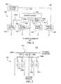
- FIG. 3depicts a block diagram of drive circuitry for the antenna array elements
- FIG. 4depicts a plan view of the antenna array elements
- FIG. 5depicts a vertical, cross sectional view of the antenna
- FIG. 6depicts an azimuth pattern produced by a planar antenna of the present invention.
- FIG. 7depicts a schematic diagram of a phase shifter that is used in the drive circuitry of FIG. 3 .
- FIG. 1is a network diagram depicting an exemplary portion of a mesh network 100 as described in commonly assigned U.S. patent application Ser. No. 10/122,886, filed Apr. 15, 2002 and application Ser. No. 10/122,762, filed Apr. 15, 2002, which are herein incorporated by reference in its entirety.
- Network 100comprises network access concentrators (SNAPs) 103 , network access points (NAPs) 101 and network access nodes 102 .
- Network trafficmay be routed from a network access node 102 to a neighboring network access node 102 .
- Such a neighboring network access node 102may route such traffic to one of its neighboring network access nodes 102 and so on until a NAP 101 or a final destination network access node 102 is reached.
- nodes 102may be in communication with one another but not with any node 101 to form a private wireless network.
- SNAPs 103may be coupled to various backhauls 105 , which backhauls 105 may be coupled to network 106 .
- Network 106may be coupled to an operations center (OC) 104 .
- Backhauls 105may form a part of network 106 .
- Network 106may comprise a portion of the Internet, a private network, or the like. By private network, it is meant a network not connected to the Internet.
- NAPs 101may be in communication with SNAPs 103 or network 106 via backhaul communication links 107 . It should be understood that backhauls may be wired or wireless. In particular, backhauls coupled to NAPs 101 may have a wireless backhaul. In an embodiment, point-to-point communication is used as between a SNAP 103 and a NAP 101 in the Unlicensed National Information Infrastructure (UNII) band (e.g., using a frequency of about 5.8 Ghz). Though, at locations where wired connectivity is available, wired connectivity may be used.
- UNIIUnlicensed National Information Infrastructure
- Network access nodes 102are in wireless communication with at least one NAP 101 or node 102 .
- nodes 102 or NAPs 101may be configured for any of or some combination of broadcasting, point-to-point communication, and multicasting.
- broadcastingit is meant transmitting without singling out any particular target recipient among a potential audience of one or more recipients.
- point-to-point communicationit is meant transmitting with singling out a particular target recipient among a potential audience of one or more recipients.
- multicastingit is meant transmitting with singling out a plurality of particular target recipients among a potential audience of recipients.
- communication between nodes 102 , between NAPs 101 , or between a NAP 101 and a node 102described below is done in terms of point-to-point communication.
- Nodes 102form, at least in part, a Wide Area Network (WAN) using in part wireless interlinks 108 . More particularly, IEEE 802.11a physical and link layer standards may be employed for communication in a range of 9 to 54 megabits per second (Mbits/s).
- WANWide Area Network
- IEEE 802.11a physical and link layer standardsmay be employed for communication in a range of 9 to 54 megabits per second (Mbits/s).
- Communication slots as described hereinare time slots with associated frequencies. However, one of ordinary skill in the art will understand that other types of communication spaces may be used, including without limitation codes, channels, and the like.
- the nodes of 102may utilize both rooftop antennas 112 or a panel mount antenna 110 (i.e., a substantially planar antenna that is adapted to be mounted to a wall or window.
- the panel mount antenna 100is capable of communicating with any mesh node 102 that is within line-of-sight to mounting location of the antenna 110 .
- FIG. 2Adepicts a top plan view of the panel mount antenna 110 communicating with neighboring nodes 102 A, 102 B and 102 C. While this figure shows communications with a signal neighbor node in each of the three possible beams, more than one neighbor node may reside in any of the beams.
- FIG. 2Bdepicts a side view of panel mount antenna 110 communicating with rooftop node 102 B.
- the panel mount antenna 110synthesizes a single, directional beam that may be switched in a multitude of directions to connect to various nodes 102 within the neighborhood as well as avoid interference sources that may exist in the neighborhood.
- panel mount antenna 110may communicate with node 102 B using a beam that is directed perpendicular from the face of the antenna 110 . In other instances, the beam may be shifted to communicate with other neighboring nodes 102 A or 102 C as described below.
- the panel mount antenna 110does not actively control the elevation of the beam, i.e., the elevation of the beam is fixed to point at a right angle from the face of the antenna.
- the neighboring rooftop nodesare typically at a slight elevation relative to the panel mount antenna.
- the panel mount antennahas a vertical beamwidth that is sufficient to receive signals from nodes at a slight elevation relative to the panel mount antenna, to maximize the signal strength coupled to a rooftop mounted antenna, the panel mount antenna 110 may be tilted either physically or electrically. Empirical study indicates that an elevation of approximately five degrees is sufficient.
- the beam elevationmay be electronically controlled in the same manner as the azimuth direction is controlled, as described below.
- FIG. 3depicts a block diagram of the antenna 110 .
- the antenna 110comprises a power delivery circuit 300 coupled to a plurality of array elements 302 .
- the power delivery circuit 300is mounted on one side of a circuit board and the array elements are mounted on the opposite side of the circuit board.
- FIG. 4depicts a top plan view of the array elements 302 .
- FIG. 5depicts a vertical, cross sectional view of the antenna 110 . To best understand the invention, the reader should simultaneously view FIGS. 3 , 4 , and 5 while reading the following description of the invention.
- the power delivery circuit 300comprises a power divider 304 , a plurality of attenuators 306 , 308 , 310 , 312 and 314 , and at least one pair of phase shifters 316 and 318 .
- the input power to the arrayis applied to terminal (e.g., port) 324 , which has, for example, a 50-ohm input impedance.
- terminal 324has, for example, a 50-ohm input impedance.
- the antennaoperates at approximately 5.8 GHz (e.g., frequencies in the UNII band).
- the power from port 324is divided by the power divider 304 into five paths 305 A-E, (i.e., a 1:5 power splitter).
- each output from the power dividercontains attenuation (a thinning of the stripline) to adjust the relative amplitudes of the signals. To maintain a low cost, the attenuation is produced in this fixed manner.
- Four of the signalsare then applied to phase shifters 316 , 318 , 320 and 322 .
- the center signal (path 305 C)is not phase shifted and forms a phase reference for the other paths 305 A, B, D, E.
- phase shifters 316 , 318 , 320 and 322operate by shifting the signals in discrete quantities using PIN diodes to vary the coupling within a hybrid coupler.
- FIG. 7depicts a schematic diagram of one of the phase shifters 316 .
- the other phase shifters 318 , 320 and 322have the same structure.
- the exemplary phase shifter 316comprises a hybrid coupler 700 and four PIN diodes 702 A, 702 B, 702 C, 702 D (collectively diodes 702 ).
- the diodesare spaced from one another along the branches 706 A and 7069 by an eighth of a wavelength and spaced from the cross arms 704 A and 704 B of the coupler 700 by an eighth of a wavelength.
- the diodes 702can be selectively biased by control signals to form a short to ground.
- the phase shiftersutilize the four PIN diodes 702 to shift the signal +90°, ⁇ 90° or 0°.
- a control circuit 320provides a bias voltage to the PIN diodes 702 .
- the phase shift from input to output of the coupler 700is ⁇ 90 degrees.
- diodes 702 B and 702 Care shorted to ground by biasing them, the phase shift through the coupler 700 is +90 degrees and, when diodes 702 A and 702 D are shorted to ground by biasing them, the phase shift through the coupler 700 is 0 degrees.
- These three discrete phase shiftsmay be applied to each of the four signal paths 305 A, B, D, E.
- the shifted signalsare applied to the array elements 302 through vias in the circuit board (see FIG. 5 below).
- FIG. 4depicts one embodiment of an arrangement for the antenna elements within the array 302 .
- This embodimentcomprises five active columns 400 , 402 , 404 , 406 and 408 .
- Each column 400 , 402 , 404 , 406 , and 408comprises eight elements 400 A-H, 402 A-H, 404 A-H, 406 A-H, and 408 A-H.
- Each elementis a radiating patch.
- the number of elements in the columndetermines the vertical beam width of the antenna. More or less than 8 elements may be used in a column.
- another type of radiating elementsuch as a slot, dipole or other aperture, could be used.
- Each element in a columnis connected to a neighboring element by a conductor 410 .
- Microwave poweris coupled to/from each column using a via 514 (shown in FIG. 5 ) that is centrally located along the columns 402 , 404 , 406 , 408 .
- each columnis spaced one half wavelength from an adjacent column. Other column spacings could be used with some degradation in the beam pattern side-lobes, one half wavelength spacing provides the optimum side-lobe levels.
- the embodimentcan logically be considered to be a seven-column array where the “phantom” columns between 400 and 402 or between 406 and 408 have infinite attenuation and are not printed on the panel. This provides the performance of a seven-column antenna using the complexity and cost of a five-column circuit.
- column 400is spaced about 5.17 cm from column 402 , while columns 402 , 404 and 406 are spaced from one another by about 2.59 cm and column 408 is spaced from column 406 by about 5.17 cm.
- the elements within each columnare equally spaced from one another by about 3.1 cm. Each element has the dimensions of about 0.9 cm by 1.4 cm. The size of each patch and the spacing between patches is wavelength dependent and would be scaled to design an antenna to other frequency bands.
- the phase shifters 316 , 318 , 320 and 322control the phase of the signal applied to each of the columns such that the antenna beam may be shifted in the horizontal plane (azimuth), but is fixed in the vertical plane (elevation). As described above, to facilitate maximizing the signal strength coupled to rooftop nodes, the vertical spacing between the elements may be adjusted to provide a slight inclination to the main beam of the antenna pattern.
- FIG. 5depicts a vertical, cross sectional view of the antenna 110 .
- the antenna 110comprises an enclosure 500 having a thickness of about 3 cm that houses a substrate, e.g., a multi-layer circuit board 502 .
- the enclosuremay be less than 3 cm thick depending upon the circuit configuration.
- the first layer 504 of metallizationcomprises the antenna elements 302
- the second layer 506 of metallizationcomprises a ground plane
- the third layer 508comprises the driver circuit 300 .
- a via 514conductively couples each column of antenna elements 302 to their respective driver circuits 300 .
- the third layer 508also could support the transceiver and modem circuits 510 .
- the antennasends and receives microwave communications signals via the antenna elements, processes the signals within the transceiver/modem circuits and provides data input and output at port 512 .
- the antenna 110can be affixed to a window 516 via suction cups 518 or other form of adhesive. In a wall-mounted configuration, the antenna may be affixed to a wall using screws or bolts.
- the technique used to mount the planar antenna 110can be adapted to any type of mounting configuration.
- the circuit board materialis a low loss material useful for fabricating microwave circuits.
- One type of low cost materialis available from Roger's Corporation as Material RO4003. This material provides a dielectric constant such that the circuit board for operation in the UNII band is 0.032 inches thick, as measured from the ground plane to the antenna elements.
- the total circuit board thicknessis 0.065 inches.
- the total circuit board sizeis 7 inches by 10 inches.
- the enclosure 500has the approximate dimensions of 3 cm thick by 25 cm tall by 20 cm wide—a size that, when installed in a window, may easily be hidden behind a curtain.
- the antenna elements 302 of the first layer 504may be separated from the ground plane 506 by a foam core or by an air gap.
- the drive circuitrycan then be assembled on a conventional printed circuit board and mounted to the ground plane on the opposite side of the antenna elements.
- foam core or air gap based circuit constructionwill further lower the cost of the panel mount antenna.
- the spacing of the elements in the horizontal and vertical planes as well as the amplitude attenuation provided by the attenuators within the drive circuitryare adjusted to compensate for the impedance of the glass (or other material) against which the antenna is mounted.
- the single main beam of the antennacan be switched +/ ⁇ 45° as well as the center.
- the antennacan be actively pointed toward the neighboring nodes to communicate with specific nodes as well as avoid unwanted interference from nodes that it is currently not communicating with as well as other microwave sources of interference.
- FIG. 6depicts the azimuth pattern 600 of the planar antenna 110 having the configuration described above for operation in the UNII band.
- the pattern 600comprises a center beam 602 , a right beam 604 and a left beam 606 .
- the antenna 110has a directive gain of 18.5 dBi with an elevation beamwidth of about 10 degrees and a azimuth beamwidth of about 47 degrees.
- the bandwidth of the antennais 150 MHz.
Landscapes
- Engineering & Computer Science (AREA)
- Computer Networks & Wireless Communication (AREA)
- Variable-Direction Aerials And Aerial Arrays (AREA)
Abstract
Description
Claims (6)
Priority Applications (7)
| Application Number | Priority Date | Filing Date | Title |
|---|---|---|---|
| US10/607,405US7053853B2 (en) | 2003-06-26 | 2003-06-26 | Planar antenna for a wireless mesh network |
| PCT/US2004/019427WO2005004278A1 (en) | 2003-06-26 | 2004-06-18 | Planar antenna for a wireless mesh network |
| EP04755547AEP1636873B1 (en) | 2003-06-26 | 2004-06-18 | Planar antenna for a wireless mesh network |
| DE602004027037TDE602004027037D1 (en) | 2003-06-26 | 2004-06-18 | |
| JP2006517363AJP2007524273A (en) | 2003-06-26 | 2004-06-18 | Planar antenna for wireless mesh networks |
| AT04755547TATE467247T1 (en) | 2003-06-26 | 2004-06-18 | PLANAR ANTENNA FOR A WIRELESS MESH NETWORK |
| KR1020057024751AKR20060029626A (en) | 2003-06-26 | 2004-06-18 | Flat antenna for wireless mesh network |
Applications Claiming Priority (1)
| Application Number | Priority Date | Filing Date | Title |
|---|---|---|---|
| US10/607,405US7053853B2 (en) | 2003-06-26 | 2003-06-26 | Planar antenna for a wireless mesh network |
Publications (2)
| Publication Number | Publication Date |
|---|---|
| US20040263390A1 US20040263390A1 (en) | 2004-12-30 |
| US7053853B2true US7053853B2 (en) | 2006-05-30 |
Family
ID=33540256
Family Applications (1)
| Application Number | Title | Priority Date | Filing Date |
|---|---|---|---|
| US10/607,405Expired - Fee RelatedUS7053853B2 (en) | 2003-06-26 | 2003-06-26 | Planar antenna for a wireless mesh network |
Country Status (7)
| Country | Link |
|---|---|
| US (1) | US7053853B2 (en) |
| EP (1) | EP1636873B1 (en) |
| JP (1) | JP2007524273A (en) |
| KR (1) | KR20060029626A (en) |
| AT (1) | ATE467247T1 (en) |
| DE (1) | DE602004027037D1 (en) |
| WO (1) | WO2005004278A1 (en) |
Cited By (31)
| Publication number | Priority date | Publication date | Assignee | Title |
|---|---|---|---|---|
| US20060182076A1 (en)* | 2005-02-17 | 2006-08-17 | Mobitrum Corporation | Method and system for mesh network embeded devices |
| US20070090996A1 (en)* | 2005-10-11 | 2007-04-26 | Mobitrum Corporation | Method and system for spatial data input, manipulation and distribution via an adaptive wireless transceiver |
| US20080025330A1 (en)* | 2006-07-27 | 2008-01-31 | Mobitrum Corporation | Method and system for dynamic information exchange on mesh network devices |
| US20090135843A1 (en)* | 2007-11-25 | 2009-05-28 | Michel Veillette | System and method for operating mesh devices in multi-tree overlapping mesh networks |
| US20090134969A1 (en)* | 2007-11-25 | 2009-05-28 | Michel Veillette | System and method for transmitting and receiving information on a neighborhood area network |
| US20090189739A1 (en)* | 2008-01-25 | 2009-07-30 | Mobitrum Corporation | Passive voice enabled rfid devices |
| US20110019587A1 (en)* | 2006-07-27 | 2011-01-27 | Mobitrum Corporation | Method and system for dynamic information exchange on location aware mesh network devices |
| US20110119360A1 (en)* | 2009-11-16 | 2011-05-19 | Kish William S | Establishing a Mesh Network with Wired and Wireless Links |
| US8305936B2 (en) | 2006-07-27 | 2012-11-06 | Mobitrum Corporation | Method and system for dynamic information exchange on a mesh network in a vehicle |
| US8332055B2 (en) | 2007-11-25 | 2012-12-11 | Trilliant Networks, Inc. | Energy use control system and method |
| US8334787B2 (en) | 2007-10-25 | 2012-12-18 | Trilliant Networks, Inc. | Gas meter having ultra-sensitive magnetic material retrofitted onto meter dial and method for performing meter retrofit |
| US8355343B2 (en) | 2008-01-11 | 2013-01-15 | Ruckus Wireless, Inc. | Determining associations in a mesh network |
| US8370697B2 (en) | 2007-11-25 | 2013-02-05 | Trilliant Networks, Inc. | System and method for power outage and restoration notification in an advanced metering infrastructure network |
| US8411590B2 (en) | 2006-07-27 | 2013-04-02 | Mobitrum Corporation | Mesh network remote control device |
| US8427979B1 (en) | 2006-07-27 | 2013-04-23 | Mobitrum Corporation | Method and system for dynamic information exchange on location aware mesh network devices |
| US8547899B2 (en) | 2007-07-28 | 2013-10-01 | Ruckus Wireless, Inc. | Wireless network throughput enhancement through channel aware scheduling |
| US8619662B2 (en) | 2004-11-05 | 2013-12-31 | Ruckus Wireless, Inc. | Unicast to multicast conversion |
| US8634402B2 (en) | 2004-11-05 | 2014-01-21 | Ruckus Wireless, Inc. | Distributed access point for IP based communications |
| US8638708B2 (en) | 2004-11-05 | 2014-01-28 | Ruckus Wireless, Inc. | MAC based mapping in IP based communications |
| US8824357B2 (en) | 2004-11-05 | 2014-09-02 | Ruckus Wireless, Inc. | Throughput enhancement by acknowledgment suppression |
| US8832428B2 (en) | 2010-11-15 | 2014-09-09 | Trilliant Holdings Inc. | System and method for securely communicating across multiple networks using a single radio |
| US8856323B2 (en) | 2011-02-10 | 2014-10-07 | Trilliant Holdings, Inc. | Device and method for facilitating secure communications over a cellular network |
| US8970394B2 (en) | 2011-01-25 | 2015-03-03 | Trilliant Holdings Inc. | Aggregated real-time power outages/restoration reporting (RTPOR) in a secure mesh network |
| US9001787B1 (en) | 2011-09-20 | 2015-04-07 | Trilliant Networks Inc. | System and method for implementing handover of a hybrid communications module |
| US9041349B2 (en) | 2011-03-08 | 2015-05-26 | Trilliant Networks, Inc. | System and method for managing load distribution across a power grid |
| US9084120B2 (en) | 2010-08-27 | 2015-07-14 | Trilliant Networks Inc. | System and method for interference free operation of co-located transceivers |
| US20160036529A1 (en)* | 2013-03-15 | 2016-02-04 | Bae Systems Plc | Directional multiband antenna |
| US9282383B2 (en) | 2011-01-14 | 2016-03-08 | Trilliant Incorporated | Process, device and system for volt/VAR optimization |
| US9999087B2 (en) | 2009-11-16 | 2018-06-12 | Ruckus Wireless, Inc. | Determining role assignment in a hybrid mesh network |
| USRE47894E1 (en) | 2006-07-27 | 2020-03-03 | Iii Holdings 2, Llc | Method and system for dynamic information exchange on location aware mesh network devices |
| US11133586B2 (en)* | 2017-10-31 | 2021-09-28 | Communication Components Antenna Inc. | Antenna array with ABFN circuitry |
Families Citing this family (14)
| Publication number | Priority date | Publication date | Assignee | Title |
|---|---|---|---|---|
| US20040201525A1 (en)* | 2003-04-08 | 2004-10-14 | Bateman Blaine R. | Antenna arrays and methods of making the same |
| WO2005104142A1 (en)* | 2004-04-22 | 2005-11-03 | Brother Kogyo Kabushiki Kaisha | Radio tag communication device |
| US20070183439A1 (en)* | 2006-01-05 | 2007-08-09 | Osann Robert Jr | Combined directional and mobile interleaved wireless mesh network |
| US20070297366A1 (en)* | 2006-01-05 | 2007-12-27 | Robert Osann | Synchronized wireless mesh network |
| US20070160020A1 (en)* | 2006-01-05 | 2007-07-12 | Robert Osann | Interleaved wireless mesh network |
| US8102868B2 (en)* | 2006-01-05 | 2012-01-24 | Folusha Forte B.V., Llc | Interleaved and directional wireless mesh network |
| US8089881B2 (en)* | 2006-03-03 | 2012-01-03 | Qualcomm Incorporated | Method and apparatus for increasing spectrum use efficiency in a mesh network |
| US20090231186A1 (en)* | 2008-02-06 | 2009-09-17 | Raysat Broadcasting Corp. | Compact electronically-steerable mobile satellite antenna system |
| KR101504041B1 (en)* | 2013-02-14 | 2015-03-18 | 하이웨이브 주식회사 | Antenna beam directivity control method and system performing the same |
| WO2014126161A1 (en)* | 2013-02-14 | 2014-08-21 | ハイウェーブ, インコ-ポレイティド | Antenna control method and antenna control system |
| US9401759B2 (en)* | 2014-10-09 | 2016-07-26 | Hughes Network Systems, Llc | Multibeam coverage for a high altitude platform |
| GB2563574B (en)* | 2017-06-05 | 2021-08-04 | International Electric Company Ltd | A phased array antenna and apparatus incorporating the same |
| US12118664B2 (en) | 2018-12-11 | 2024-10-15 | L3Vel, Llc | Systems and methods for designing and deploying wireless communication mesh networks |
| WO2020123669A1 (en)* | 2018-12-11 | 2020-06-18 | Kevin Ross | Systems and methods for designing and deploying wireless communication mesh networks |
Citations (40)
| Publication number | Priority date | Publication date | Assignee | Title |
|---|---|---|---|---|
| US4259674A (en) | 1979-10-24 | 1981-03-31 | Bell Laboratories | Phased array antenna arrangement with filtering to reduce grating lobes |
| US4602257A (en)* | 1984-06-15 | 1986-07-22 | Grisham William H | Method of satellite operation using synthetic aperture radar addition holography for imaging |
| US4728960A (en) | 1986-06-10 | 1988-03-01 | The United States Of America As Represented By The Secretary Of The Air Force | Multifunctional microstrip antennas |
| US4784147A (en) | 1986-12-08 | 1988-11-15 | North American Philips Corporation | Method and apparatus for sidelobe suppression in scanning imaging systems |
| JPH01274505A (en) | 1988-04-27 | 1989-11-02 | Mitsubishi Electric Corp | Patch antenna |
| JPH01279604A (en) | 1988-05-06 | 1989-11-09 | Mitsubishi Electric Corp | Microstrip antenna |
| US5181042A (en) | 1988-05-13 | 1993-01-19 | Yagi Antenna Co., Ltd. | Microstrip array antenna |
| US5210541A (en) | 1989-02-03 | 1993-05-11 | The Secretary Of State For Defence In Her Britannic Majesty's Government Of The United Kingdom Of Great Britain And Northern Ireland | Microstrip patch antenna arrays |
| JPH06314923A (en) | 1993-04-19 | 1994-11-08 | Wireless Access Inc | Small double ring microstrip antenna |
| US5686928A (en) | 1995-10-13 | 1997-11-11 | Lockheed Martin Corporation | Phased array antenna for radio frequency identification |
| US5751248A (en) | 1994-10-13 | 1998-05-12 | The Boeing Company | Phased array beam controller using integrated electro-optic circuits |
| US5832389A (en) | 1994-03-24 | 1998-11-03 | Ericsson Inc. | Wideband digitization systems and methods for cellular radiotelephones |
| US5936592A (en)* | 1998-06-05 | 1999-08-10 | Ramanujam; Parthasarathy | Reconfigurable multiple beam satellite reflector antenna with an array feed |
| US6037911A (en) | 1997-06-30 | 2000-03-14 | Sony International (Europe) Gmbh | Wide bank printed phase array antenna for microwave and mm-wave applications |
| US6229486B1 (en) | 1998-09-10 | 2001-05-08 | David James Krile | Subscriber based smart antenna |
| US6266011B1 (en)* | 1999-09-30 | 2001-07-24 | Rockwell Science Center, Llc | Electronically scanned phased array antenna system and method with scan control independent of radiating frequency |
| JP2001244717A (en) | 2000-03-02 | 2001-09-07 | Matsushita Electric Ind Co Ltd | Wireless information home appliances |
| US6292133B1 (en) | 1999-07-26 | 2001-09-18 | Harris Corporation | Array antenna with selectable scan angles |
| JP2001284951A (en) | 2000-02-29 | 2001-10-12 | Lucent Technol Inc | Patch antenna having limited ground plane |
| US6317095B1 (en)* | 1998-09-30 | 2001-11-13 | Anritsu Corporation | Planar antenna and method for manufacturing the same |
| US6369770B1 (en)* | 2001-01-31 | 2002-04-09 | Tantivy Communications, Inc. | Closely spaced antenna array |
| US20020052960A1 (en) | 2000-06-15 | 2002-05-02 | Tjandra Trisno | Automatic assignment of addresses to nodes in a network |
| US6407705B1 (en) | 2000-06-27 | 2002-06-18 | Mohamed Said Sanad | Compact broadband high efficiency microstrip antenna for wireless modems |
| US6426814B1 (en) | 1999-10-13 | 2002-07-30 | Caly Corporation | Spatially switched router for wireless data packets |
| US6433742B1 (en) | 2000-10-19 | 2002-08-13 | Magis Networks, Inc. | Diversity antenna structure for wireless communications |
| US6438367B1 (en) | 2000-11-09 | 2002-08-20 | Magis Networks, Inc. | Transmission security for wireless communications |
| US6456245B1 (en) | 2000-12-13 | 2002-09-24 | Magis Networks, Inc. | Card-based diversity antenna structure for wireless communications |
| US20020137547A1 (en) | 2001-02-07 | 2002-09-26 | Judson Bruce A. | Antenna array and method therefor |
| US20020136062A1 (en) | 2001-02-15 | 2002-09-26 | Mark Peting | Memory array organization for static arrays |
| US20020176381A1 (en) | 2001-04-18 | 2002-11-28 | Skypilot Network, Inc. | Network channel access protocol - slot allocation |
| US20020175859A1 (en) | 2001-05-17 | 2002-11-28 | Newberg Irwin L. | Phased array antenna system with virtual time delay beam steering |
| US20020181427A1 (en) | 2001-04-18 | 2002-12-05 | Skypilot Network, Inc. | Wireless mesh network |
| US20030017851A1 (en) | 2001-02-28 | 2003-01-23 | Mohammad Ghavami | Wide-band array antenna |
| US20030030594A1 (en) | 2001-07-30 | 2003-02-13 | Thomas Larry | Small controlled parasitic antenna system and method for controlling same to optimally improve signal quality |
| US20030038748A1 (en) | 2001-08-27 | 2003-02-27 | Henderson Herbert Jefferson | Dynamic multi-beam antenna using dielectrically tunable phase shifters |
| US6583760B2 (en)* | 1998-12-17 | 2003-06-24 | Metawave Communications Corporation | Dual mode switched beam antenna |
| US6710742B1 (en)* | 2001-10-23 | 2004-03-23 | Kathrein-Werke Kg | Active antenna roof top system and method |
| US6756939B2 (en)* | 2000-07-21 | 2004-06-29 | Paratek Microwave, Inc. | Phased array antennas incorporating voltage-tunable phase shifters |
| US6765530B1 (en)* | 2002-07-16 | 2004-07-20 | Ball Aerospace & Technologies Corp. | Array antenna having pairs of antenna elements |
| US6816116B2 (en)* | 2002-03-22 | 2004-11-09 | Quanta Computer, Inc. | Smart antenna for portable devices |
Family Cites Families (10)
| Publication number | Priority date | Publication date | Assignee | Title |
|---|---|---|---|---|
| JPH03171802A (en)* | 1989-11-29 | 1991-07-25 | Mitsubishi Electric Corp | Large planar antenna |
| JPH0644216U (en)* | 1992-06-26 | 1994-06-10 | 三洋電機株式会社 | Planar antenna |
| JPH06334429A (en)* | 1993-05-26 | 1994-12-02 | Toyota Central Res & Dev Lab Inc | Tracking antenna device |
| US5548813A (en)* | 1994-03-24 | 1996-08-20 | Ericsson Inc. | Phased array cellular base station and associated methods for enhanced power efficiency |
| JP3456507B2 (en)* | 1996-04-15 | 2003-10-14 | 日本電信電話株式会社 | Sector antenna |
| JP3792013B2 (en)* | 1997-08-12 | 2006-06-28 | 富士通株式会社 | Wireless LAN and in-system transmission / reception device |
| DE10012080C1 (en)* | 2000-03-14 | 2001-10-31 | Daimler Chrysler Ag | Antenna array and method for operating an antenna array |
| AU3289602A (en)* | 2000-11-10 | 2002-05-21 | Am Group Corp | Direction-agile antenna system for wireless communications |
| GB0030932D0 (en)* | 2000-12-19 | 2001-01-31 | Radiant Networks Plc | Antenna apparatus, communications apparatus and method of transmission |
| JP3802405B2 (en)* | 2001-11-30 | 2006-07-26 | 日本放送協会 | Active slot antenna, active slot array antenna, and transmitter and receiver using the same |
- 2003
- 2003-06-26USUS10/607,405patent/US7053853B2/ennot_activeExpired - Fee Related
- 2004
- 2004-06-18ATAT04755547Tpatent/ATE467247T1/ennot_activeIP Right Cessation
- 2004-06-18WOPCT/US2004/019427patent/WO2005004278A1/enactiveApplication Filing
- 2004-06-18EPEP04755547Apatent/EP1636873B1/ennot_activeExpired - Lifetime
- 2004-06-18DEDE602004027037Tpatent/DE602004027037D1/denot_activeExpired - Fee Related
- 2004-06-18JPJP2006517363Apatent/JP2007524273A/enactivePending
- 2004-06-18KRKR1020057024751Apatent/KR20060029626A/ennot_activeCeased
Patent Citations (40)
| Publication number | Priority date | Publication date | Assignee | Title |
|---|---|---|---|---|
| US4259674A (en) | 1979-10-24 | 1981-03-31 | Bell Laboratories | Phased array antenna arrangement with filtering to reduce grating lobes |
| US4602257A (en)* | 1984-06-15 | 1986-07-22 | Grisham William H | Method of satellite operation using synthetic aperture radar addition holography for imaging |
| US4728960A (en) | 1986-06-10 | 1988-03-01 | The United States Of America As Represented By The Secretary Of The Air Force | Multifunctional microstrip antennas |
| US4784147A (en) | 1986-12-08 | 1988-11-15 | North American Philips Corporation | Method and apparatus for sidelobe suppression in scanning imaging systems |
| JPH01274505A (en) | 1988-04-27 | 1989-11-02 | Mitsubishi Electric Corp | Patch antenna |
| JPH01279604A (en) | 1988-05-06 | 1989-11-09 | Mitsubishi Electric Corp | Microstrip antenna |
| US5181042A (en) | 1988-05-13 | 1993-01-19 | Yagi Antenna Co., Ltd. | Microstrip array antenna |
| US5210541A (en) | 1989-02-03 | 1993-05-11 | The Secretary Of State For Defence In Her Britannic Majesty's Government Of The United Kingdom Of Great Britain And Northern Ireland | Microstrip patch antenna arrays |
| JPH06314923A (en) | 1993-04-19 | 1994-11-08 | Wireless Access Inc | Small double ring microstrip antenna |
| US5832389A (en) | 1994-03-24 | 1998-11-03 | Ericsson Inc. | Wideband digitization systems and methods for cellular radiotelephones |
| US5751248A (en) | 1994-10-13 | 1998-05-12 | The Boeing Company | Phased array beam controller using integrated electro-optic circuits |
| US5686928A (en) | 1995-10-13 | 1997-11-11 | Lockheed Martin Corporation | Phased array antenna for radio frequency identification |
| US6037911A (en) | 1997-06-30 | 2000-03-14 | Sony International (Europe) Gmbh | Wide bank printed phase array antenna for microwave and mm-wave applications |
| US5936592A (en)* | 1998-06-05 | 1999-08-10 | Ramanujam; Parthasarathy | Reconfigurable multiple beam satellite reflector antenna with an array feed |
| US6229486B1 (en) | 1998-09-10 | 2001-05-08 | David James Krile | Subscriber based smart antenna |
| US6317095B1 (en)* | 1998-09-30 | 2001-11-13 | Anritsu Corporation | Planar antenna and method for manufacturing the same |
| US6583760B2 (en)* | 1998-12-17 | 2003-06-24 | Metawave Communications Corporation | Dual mode switched beam antenna |
| US6292133B1 (en) | 1999-07-26 | 2001-09-18 | Harris Corporation | Array antenna with selectable scan angles |
| US6266011B1 (en)* | 1999-09-30 | 2001-07-24 | Rockwell Science Center, Llc | Electronically scanned phased array antenna system and method with scan control independent of radiating frequency |
| US6426814B1 (en) | 1999-10-13 | 2002-07-30 | Caly Corporation | Spatially switched router for wireless data packets |
| JP2001284951A (en) | 2000-02-29 | 2001-10-12 | Lucent Technol Inc | Patch antenna having limited ground plane |
| JP2001244717A (en) | 2000-03-02 | 2001-09-07 | Matsushita Electric Ind Co Ltd | Wireless information home appliances |
| US20020052960A1 (en) | 2000-06-15 | 2002-05-02 | Tjandra Trisno | Automatic assignment of addresses to nodes in a network |
| US6407705B1 (en) | 2000-06-27 | 2002-06-18 | Mohamed Said Sanad | Compact broadband high efficiency microstrip antenna for wireless modems |
| US6756939B2 (en)* | 2000-07-21 | 2004-06-29 | Paratek Microwave, Inc. | Phased array antennas incorporating voltage-tunable phase shifters |
| US6433742B1 (en) | 2000-10-19 | 2002-08-13 | Magis Networks, Inc. | Diversity antenna structure for wireless communications |
| US6438367B1 (en) | 2000-11-09 | 2002-08-20 | Magis Networks, Inc. | Transmission security for wireless communications |
| US6456245B1 (en) | 2000-12-13 | 2002-09-24 | Magis Networks, Inc. | Card-based diversity antenna structure for wireless communications |
| US6369770B1 (en)* | 2001-01-31 | 2002-04-09 | Tantivy Communications, Inc. | Closely spaced antenna array |
| US20020137547A1 (en) | 2001-02-07 | 2002-09-26 | Judson Bruce A. | Antenna array and method therefor |
| US20020136062A1 (en) | 2001-02-15 | 2002-09-26 | Mark Peting | Memory array organization for static arrays |
| US20030017851A1 (en) | 2001-02-28 | 2003-01-23 | Mohammad Ghavami | Wide-band array antenna |
| US20020176381A1 (en) | 2001-04-18 | 2002-11-28 | Skypilot Network, Inc. | Network channel access protocol - slot allocation |
| US20020181427A1 (en) | 2001-04-18 | 2002-12-05 | Skypilot Network, Inc. | Wireless mesh network |
| US20020175859A1 (en) | 2001-05-17 | 2002-11-28 | Newberg Irwin L. | Phased array antenna system with virtual time delay beam steering |
| US20030030594A1 (en) | 2001-07-30 | 2003-02-13 | Thomas Larry | Small controlled parasitic antenna system and method for controlling same to optimally improve signal quality |
| US20030038748A1 (en) | 2001-08-27 | 2003-02-27 | Henderson Herbert Jefferson | Dynamic multi-beam antenna using dielectrically tunable phase shifters |
| US6710742B1 (en)* | 2001-10-23 | 2004-03-23 | Kathrein-Werke Kg | Active antenna roof top system and method |
| US6816116B2 (en)* | 2002-03-22 | 2004-11-09 | Quanta Computer, Inc. | Smart antenna for portable devices |
| US6765530B1 (en)* | 2002-07-16 | 2004-07-20 | Ball Aerospace & Technologies Corp. | Array antenna having pairs of antenna elements |
Non-Patent Citations (1)
| Title |
|---|
| Copy of International Search Report dated Oct. 4, 2004 for corresponding PCT application, PCT/US2004/019427. |
Cited By (48)
| Publication number | Priority date | Publication date | Assignee | Title |
|---|---|---|---|---|
| US9019886B2 (en) | 2004-11-05 | 2015-04-28 | Ruckus Wireless, Inc. | Unicast to multicast conversion |
| US8824357B2 (en) | 2004-11-05 | 2014-09-02 | Ruckus Wireless, Inc. | Throughput enhancement by acknowledgment suppression |
| US9794758B2 (en) | 2004-11-05 | 2017-10-17 | Ruckus Wireless, Inc. | Increasing reliable data throughput in a wireless network |
| US9661475B2 (en) | 2004-11-05 | 2017-05-23 | Ruckus Wireless, Inc. | Distributed access point for IP based communications |
| US9240868B2 (en) | 2004-11-05 | 2016-01-19 | Ruckus Wireless, Inc. | Increasing reliable data throughput in a wireless network |
| US9071942B2 (en) | 2004-11-05 | 2015-06-30 | Ruckus Wireless, Inc. | MAC based mapping in IP based communications |
| US9066152B2 (en) | 2004-11-05 | 2015-06-23 | Ruckus Wireless, Inc. | Distributed access point for IP based communications |
| US8634402B2 (en) | 2004-11-05 | 2014-01-21 | Ruckus Wireless, Inc. | Distributed access point for IP based communications |
| US8638708B2 (en) | 2004-11-05 | 2014-01-28 | Ruckus Wireless, Inc. | MAC based mapping in IP based communications |
| US8619662B2 (en) | 2004-11-05 | 2013-12-31 | Ruckus Wireless, Inc. | Unicast to multicast conversion |
| US7586888B2 (en) | 2005-02-17 | 2009-09-08 | Mobitrum Corporation | Method and system for mesh network embedded devices |
| US20060182076A1 (en)* | 2005-02-17 | 2006-08-17 | Mobitrum Corporation | Method and system for mesh network embeded devices |
| US20070090996A1 (en)* | 2005-10-11 | 2007-04-26 | Mobitrum Corporation | Method and system for spatial data input, manipulation and distribution via an adaptive wireless transceiver |
| US7630736B2 (en) | 2005-10-11 | 2009-12-08 | Mobitrum Corporation | Method and system for spatial data input, manipulation and distribution via an adaptive wireless transceiver |
| US8305936B2 (en) | 2006-07-27 | 2012-11-06 | Mobitrum Corporation | Method and system for dynamic information exchange on a mesh network in a vehicle |
| US20110019587A1 (en)* | 2006-07-27 | 2011-01-27 | Mobitrum Corporation | Method and system for dynamic information exchange on location aware mesh network devices |
| USRE47894E1 (en) | 2006-07-27 | 2020-03-03 | Iii Holdings 2, Llc | Method and system for dynamic information exchange on location aware mesh network devices |
| US8411590B2 (en) | 2006-07-27 | 2013-04-02 | Mobitrum Corporation | Mesh network remote control device |
| US8427979B1 (en) | 2006-07-27 | 2013-04-23 | Mobitrum Corporation | Method and system for dynamic information exchange on location aware mesh network devices |
| US20080025330A1 (en)* | 2006-07-27 | 2008-01-31 | Mobitrum Corporation | Method and system for dynamic information exchange on mesh network devices |
| US7801058B2 (en) | 2006-07-27 | 2010-09-21 | Mobitrum Corporation | Method and system for dynamic information exchange on mesh network devices |
| US8305935B2 (en) | 2006-07-27 | 2012-11-06 | Mobitrum Corporation | Method and system for dynamic information exchange on location aware mesh network devices |
| US9674862B2 (en) | 2007-07-28 | 2017-06-06 | Ruckus Wireless, Inc. | Wireless network throughput enhancement through channel aware scheduling |
| US9271327B2 (en) | 2007-07-28 | 2016-02-23 | Ruckus Wireless, Inc. | Wireless network throughput enhancement through channel aware scheduling |
| US8547899B2 (en) | 2007-07-28 | 2013-10-01 | Ruckus Wireless, Inc. | Wireless network throughput enhancement through channel aware scheduling |
| US8334787B2 (en) | 2007-10-25 | 2012-12-18 | Trilliant Networks, Inc. | Gas meter having ultra-sensitive magnetic material retrofitted onto meter dial and method for performing meter retrofit |
| US8332055B2 (en) | 2007-11-25 | 2012-12-11 | Trilliant Networks, Inc. | Energy use control system and method |
| US8725274B2 (en) | 2007-11-25 | 2014-05-13 | Trilliant Networks, Inc. | Energy use control system and method |
| US8370697B2 (en) | 2007-11-25 | 2013-02-05 | Trilliant Networks, Inc. | System and method for power outage and restoration notification in an advanced metering infrastructure network |
| US8502640B2 (en) | 2007-11-25 | 2013-08-06 | Trilliant Networks, Inc. | System and method for transmitting and receiving information on a neighborhood area network |
| US20090135843A1 (en)* | 2007-11-25 | 2009-05-28 | Michel Veillette | System and method for operating mesh devices in multi-tree overlapping mesh networks |
| US20090134969A1 (en)* | 2007-11-25 | 2009-05-28 | Michel Veillette | System and method for transmitting and receiving information on a neighborhood area network |
| US8780760B2 (en) | 2008-01-11 | 2014-07-15 | Ruckus Wireless, Inc. | Determining associations in a mesh network |
| US8355343B2 (en) | 2008-01-11 | 2013-01-15 | Ruckus Wireless, Inc. | Determining associations in a mesh network |
| US20090189739A1 (en)* | 2008-01-25 | 2009-07-30 | Mobitrum Corporation | Passive voice enabled rfid devices |
| US20110119360A1 (en)* | 2009-11-16 | 2011-05-19 | Kish William S | Establishing a Mesh Network with Wired and Wireless Links |
| US9999087B2 (en) | 2009-11-16 | 2018-06-12 | Ruckus Wireless, Inc. | Determining role assignment in a hybrid mesh network |
| US9979626B2 (en) | 2009-11-16 | 2018-05-22 | Ruckus Wireless, Inc. | Establishing a mesh network with wired and wireless links |
| US9084120B2 (en) | 2010-08-27 | 2015-07-14 | Trilliant Networks Inc. | System and method for interference free operation of co-located transceivers |
| US8832428B2 (en) | 2010-11-15 | 2014-09-09 | Trilliant Holdings Inc. | System and method for securely communicating across multiple networks using a single radio |
| US9282383B2 (en) | 2011-01-14 | 2016-03-08 | Trilliant Incorporated | Process, device and system for volt/VAR optimization |
| US8970394B2 (en) | 2011-01-25 | 2015-03-03 | Trilliant Holdings Inc. | Aggregated real-time power outages/restoration reporting (RTPOR) in a secure mesh network |
| US8856323B2 (en) | 2011-02-10 | 2014-10-07 | Trilliant Holdings, Inc. | Device and method for facilitating secure communications over a cellular network |
| US9041349B2 (en) | 2011-03-08 | 2015-05-26 | Trilliant Networks, Inc. | System and method for managing load distribution across a power grid |
| US9001787B1 (en) | 2011-09-20 | 2015-04-07 | Trilliant Networks Inc. | System and method for implementing handover of a hybrid communications module |
| US9692512B2 (en)* | 2013-03-15 | 2017-06-27 | Bae Systems Plc | Directional multiband antenna |
| US20160036529A1 (en)* | 2013-03-15 | 2016-02-04 | Bae Systems Plc | Directional multiband antenna |
| US11133586B2 (en)* | 2017-10-31 | 2021-09-28 | Communication Components Antenna Inc. | Antenna array with ABFN circuitry |
Also Published As
| Publication number | Publication date |
|---|---|
| ATE467247T1 (en) | 2010-05-15 |
| DE602004027037D1 (en) | 2010-06-17 |
| EP1636873A1 (en) | 2006-03-22 |
| EP1636873B1 (en) | 2010-05-05 |
| WO2005004278A1 (en) | 2005-01-13 |
| KR20060029626A (en) | 2006-04-06 |
| US20040263390A1 (en) | 2004-12-30 |
| JP2007524273A (en) | 2007-08-23 |
Similar Documents
| Publication | Publication Date | Title |
|---|---|---|
| US7053853B2 (en) | Planar antenna for a wireless mesh network | |
| US6864853B2 (en) | Combination directional/omnidirectional antenna | |
| US9761937B2 (en) | Fragmented aperture for the Ka/K/Ku frequency bands | |
| US8587492B2 (en) | Dual-polarized multi-band, full duplex, interleaved waveguide antenna aperture | |
| US20230268640A1 (en) | Base station antennas having arrays of radiating elements with 4 ports without usage of diplexers | |
| CA2076990C (en) | Slotted microstrip electronic scan antenna | |
| US20020175862A1 (en) | Antenna array | |
| US11962072B2 (en) | Phased array antennas having switched elevation beamwidths and related methods | |
| US11411301B2 (en) | Compact multiband feed for small cell base station antennas | |
| US10374292B2 (en) | Wireless backhaul network using traveling wave antennas | |
| US6049305A (en) | Compact antenna for low and medium earth orbit satellite communication systems | |
| CN114520409A (en) | Base Station Antenna with Partially Shared Wideband Beamforming Array | |
| KR100748337B1 (en) | Dual Polarization Diversity Active Microstrip Array Antenna | |
| US20250046999A1 (en) | High performance patch-type radiating elements for massive mimo communication systems | |
| WO2019136255A1 (en) | Corner antenna array devices systems, and methods | |
| KR20080028408A (en) | Improved repeater antenna | |
| KR20020041771A (en) | IMT2000 Microstrip patch array antenna | |
| KR102428139B1 (en) | Uniform circular array antenna for milimeter wave | |
| KR100449836B1 (en) | Wideband Microstrip Patch Antenna for Transmitting/Receiving and Array Antenna Arraying it | |
| KR20020061717A (en) | Microstrip beam forming antenna | |
| WO2007141281A1 (en) | A dual-polar antenna for a base station of mobile radio systems with adjustable azimuth beamwidth | |
| EP4218099A1 (en) | A mobile communication antenna for transmitting and/or receiving mobile communication signals | |
| WO2007004930A1 (en) | An improved repeater antenna for use in point-to-point applications | |
| Hettak et al. | Millimeter wave mobile access system with intelligent antenna and radio on fiber |
Legal Events
| Date | Code | Title | Description |
|---|---|---|---|
| AS | Assignment | Owner name:SKYPILOT NETWORK, INC., CALIFORNIA Free format text:ASSIGNMENT OF ASSIGNORS INTEREST;ASSIGNORS:MERENDA, JOSEPH;RICH, MARK J.;REEL/FRAME:014243/0158;SIGNING DATES FROM 20030618 TO 20030623 | |
| AS | Assignment | Owner name:MOBIUS TECHNOLOGY VENTURES VI, L.P., COLORADO Free format text:SECURITY AGREEMENT;ASSIGNOR:SKYPILOT NETWORKS, INC.;REEL/FRAME:020125/0417 Effective date:20071107 Owner name:SOFTBANK U.S. VENTURES VI, L.P., COLORADO Free format text:SECURITY AGREEMENT;ASSIGNOR:SKYPILOT NETWORKS, INC.;REEL/FRAME:020125/0417 Effective date:20071107 Owner name:MOBIUS TECHNOLOGY VENTURES ADVISORS FUND VI, L.P., Free format text:SECURITY AGREEMENT;ASSIGNOR:SKYPILOT NETWORKS, INC.;REEL/FRAME:020125/0417 Effective date:20071107 Owner name:MOBIUS TECHNOLOGY VENTURES SIDE FUND VI, L.P., COL Free format text:SECURITY AGREEMENT;ASSIGNOR:SKYPILOT NETWORKS, INC.;REEL/FRAME:020125/0417 Effective date:20071107 Owner name:AUGUST CAPITAL IV, L.P., CALIFORNIA Free format text:SECURITY AGREEMENT;ASSIGNOR:SKYPILOT NETWORKS, INC.;REEL/FRAME:020125/0417 Effective date:20071107 Owner name:MOBIUS TECHNOLOGY VENTURES VI, L.P.,COLORADO Free format text:SECURITY AGREEMENT;ASSIGNOR:SKYPILOT NETWORKS, INC.;REEL/FRAME:020125/0417 Effective date:20071107 Owner name:SOFTBANK U.S. VENTURES VI, L.P.,COLORADO Free format text:SECURITY AGREEMENT;ASSIGNOR:SKYPILOT NETWORKS, INC.;REEL/FRAME:020125/0417 Effective date:20071107 Owner name:MOBIUS TECHNOLOGY VENTURES SIDE FUND VI, L.P.,COLO Free format text:SECURITY AGREEMENT;ASSIGNOR:SKYPILOT NETWORKS, INC.;REEL/FRAME:020125/0417 Effective date:20071107 Owner name:AUGUST CAPITAL IV, L.P.,CALIFORNIA Free format text:SECURITY AGREEMENT;ASSIGNOR:SKYPILOT NETWORKS, INC.;REEL/FRAME:020125/0417 Effective date:20071107 | |
| AS | Assignment | Owner name:TRILLIANT NETWORKS, INC., CALIFORNIA Free format text:ASSIGNMENT OF ASSIGNORS INTEREST;ASSIGNOR:SKYPILOT NETWORKS, INC.;REEL/FRAME:023175/0622 Effective date:20090831 Owner name:TRILLIANT NETWORKS, INC.,CALIFORNIA Free format text:ASSIGNMENT OF ASSIGNORS INTEREST;ASSIGNOR:SKYPILOT NETWORKS, INC.;REEL/FRAME:023175/0622 Effective date:20090831 | |
| AS | Assignment | Owner name:SKYPILOT NETWORKS, INC., CALIFORNIA Free format text:CHANGE OF NAME;ASSIGNOR:SKYPILOT NETWORK, INC.;REEL/FRAME:023201/0026 Effective date:20050419 | |
| FPAY | Fee payment | Year of fee payment:4 | |
| FPAY | Fee payment | Year of fee payment:8 | |
| FEPP | Fee payment procedure | Free format text:MAINTENANCE FEE REMINDER MAILED (ORIGINAL EVENT CODE: REM.) | |
| LAPS | Lapse for failure to pay maintenance fees | Free format text:PATENT EXPIRED FOR FAILURE TO PAY MAINTENANCE FEES (ORIGINAL EVENT CODE: EXP.) | |
| STCH | Information on status: patent discontinuation | Free format text:PATENT EXPIRED DUE TO NONPAYMENT OF MAINTENANCE FEES UNDER 37 CFR 1.362 | |
| FP | Lapsed due to failure to pay maintenance fee | Effective date:20180530 |