US7052516B2 - Spinal disc annulus reconstruction method and deformable spinal disc annulus stent - Google Patents
Spinal disc annulus reconstruction method and deformable spinal disc annulus stentDownload PDFInfo
- Publication number
- US7052516B2 US7052516B2US10/133,339US13333902AUS7052516B2US 7052516 B2US7052516 B2US 7052516B2US 13333902 AUS13333902 AUS 13333902AUS 7052516 B2US7052516 B2US 7052516B2
- Authority
- US
- United States
- Prior art keywords
- annulus
- aperture
- stent
- patch
- disc
- Prior art date
- Legal status (The legal status is an assumption and is not a legal conclusion. Google has not performed a legal analysis and makes no representation as to the accuracy of the status listed.)
- Expired - Lifetime, expires
Links
Images


Classifications
- A—HUMAN NECESSITIES
- A61—MEDICAL OR VETERINARY SCIENCE; HYGIENE
- A61F—FILTERS IMPLANTABLE INTO BLOOD VESSELS; PROSTHESES; DEVICES PROVIDING PATENCY TO, OR PREVENTING COLLAPSING OF, TUBULAR STRUCTURES OF THE BODY, e.g. STENTS; ORTHOPAEDIC, NURSING OR CONTRACEPTIVE DEVICES; FOMENTATION; TREATMENT OR PROTECTION OF EYES OR EARS; BANDAGES, DRESSINGS OR ABSORBENT PADS; FIRST-AID KITS
- A61F2/00—Filters implantable into blood vessels; Prostheses, i.e. artificial substitutes or replacements for parts of the body; Appliances for connecting them with the body; Devices providing patency to, or preventing collapsing of, tubular structures of the body, e.g. stents
- A61F2/02—Prostheses implantable into the body
- A61F2/30—Joints
- A61F2/44—Joints for the spine, e.g. vertebrae, spinal discs
- A61F2/441—Joints for the spine, e.g. vertebrae, spinal discs made of inflatable pockets or chambers filled with fluid, e.g. with hydrogel
- A—HUMAN NECESSITIES
- A61—MEDICAL OR VETERINARY SCIENCE; HYGIENE
- A61F—FILTERS IMPLANTABLE INTO BLOOD VESSELS; PROSTHESES; DEVICES PROVIDING PATENCY TO, OR PREVENTING COLLAPSING OF, TUBULAR STRUCTURES OF THE BODY, e.g. STENTS; ORTHOPAEDIC, NURSING OR CONTRACEPTIVE DEVICES; FOMENTATION; TREATMENT OR PROTECTION OF EYES OR EARS; BANDAGES, DRESSINGS OR ABSORBENT PADS; FIRST-AID KITS
- A61F2/00—Filters implantable into blood vessels; Prostheses, i.e. artificial substitutes or replacements for parts of the body; Appliances for connecting them with the body; Devices providing patency to, or preventing collapsing of, tubular structures of the body, e.g. stents
- A61F2/02—Prostheses implantable into the body
- A61F2/30—Joints
- A61F2/44—Joints for the spine, e.g. vertebrae, spinal discs
- A61F2/442—Intervertebral or spinal discs, e.g. resilient
- A—HUMAN NECESSITIES
- A61—MEDICAL OR VETERINARY SCIENCE; HYGIENE
- A61F—FILTERS IMPLANTABLE INTO BLOOD VESSELS; PROSTHESES; DEVICES PROVIDING PATENCY TO, OR PREVENTING COLLAPSING OF, TUBULAR STRUCTURES OF THE BODY, e.g. STENTS; ORTHOPAEDIC, NURSING OR CONTRACEPTIVE DEVICES; FOMENTATION; TREATMENT OR PROTECTION OF EYES OR EARS; BANDAGES, DRESSINGS OR ABSORBENT PADS; FIRST-AID KITS
- A61F2/00—Filters implantable into blood vessels; Prostheses, i.e. artificial substitutes or replacements for parts of the body; Appliances for connecting them with the body; Devices providing patency to, or preventing collapsing of, tubular structures of the body, e.g. stents
- A61F2/02—Prostheses implantable into the body
- A61F2/30—Joints
- A61F2/46—Special tools for implanting artificial joints
- A61F2/4603—Special tools for implanting artificial joints for insertion or extraction of endoprosthetic joints or of accessories thereof
- A61F2/4611—Special tools for implanting artificial joints for insertion or extraction of endoprosthetic joints or of accessories thereof of spinal prostheses
- A—HUMAN NECESSITIES
- A61—MEDICAL OR VETERINARY SCIENCE; HYGIENE
- A61B—DIAGNOSIS; SURGERY; IDENTIFICATION
- A61B17/00—Surgical instruments, devices or methods
- A61B17/04—Surgical instruments, devices or methods for suturing wounds; Holders or packages for needles or suture materials
- A—HUMAN NECESSITIES
- A61—MEDICAL OR VETERINARY SCIENCE; HYGIENE
- A61B—DIAGNOSIS; SURGERY; IDENTIFICATION
- A61B17/00—Surgical instruments, devices or methods
- A61B17/04—Surgical instruments, devices or methods for suturing wounds; Holders or packages for needles or suture materials
- A61B17/06—Needles ; Sutures; Needle-suture combinations; Holders or packages for needles or suture materials
- A61B17/06166—Sutures
- A—HUMAN NECESSITIES
- A61—MEDICAL OR VETERINARY SCIENCE; HYGIENE
- A61B—DIAGNOSIS; SURGERY; IDENTIFICATION
- A61B17/00—Surgical instruments, devices or methods
- A61B17/064—Surgical staples, i.e. penetrating the tissue
- A61B17/0642—Surgical staples, i.e. penetrating the tissue for bones, e.g. for osteosynthesis or connecting tendon to bone
- A—HUMAN NECESSITIES
- A61—MEDICAL OR VETERINARY SCIENCE; HYGIENE
- A61B—DIAGNOSIS; SURGERY; IDENTIFICATION
- A61B17/00—Surgical instruments, devices or methods
- A61B17/56—Surgical instruments or methods for treatment of bones or joints; Devices specially adapted therefor
- A61B17/58—Surgical instruments or methods for treatment of bones or joints; Devices specially adapted therefor for osteosynthesis, e.g. bone plates, screws or setting implements
- A61B17/68—Internal fixation devices, including fasteners and spinal fixators, even if a part thereof projects from the skin
- A61B17/84—Fasteners therefor or fasteners being internal fixation devices
- A61B17/86—Pins or screws or threaded wires; nuts therefor
- A—HUMAN NECESSITIES
- A61—MEDICAL OR VETERINARY SCIENCE; HYGIENE
- A61B—DIAGNOSIS; SURGERY; IDENTIFICATION
- A61B17/00—Surgical instruments, devices or methods
- A61B2017/00004—(bio)absorbable, (bio)resorbable or resorptive
- A—HUMAN NECESSITIES
- A61—MEDICAL OR VETERINARY SCIENCE; HYGIENE
- A61B—DIAGNOSIS; SURGERY; IDENTIFICATION
- A61B17/00—Surgical instruments, devices or methods
- A61B17/04—Surgical instruments, devices or methods for suturing wounds; Holders or packages for needles or suture materials
- A61B17/06—Needles ; Sutures; Needle-suture combinations; Holders or packages for needles or suture materials
- A61B17/06166—Sutures
- A61B2017/06176—Sutures with protrusions, e.g. barbs
- A—HUMAN NECESSITIES
- A61—MEDICAL OR VETERINARY SCIENCE; HYGIENE
- A61B—DIAGNOSIS; SURGERY; IDENTIFICATION
- A61B17/00—Surgical instruments, devices or methods
- A61B17/064—Surgical staples, i.e. penetrating the tissue
- A61B2017/0641—Surgical staples, i.e. penetrating the tissue having at least three legs as part of one single body
- A—HUMAN NECESSITIES
- A61—MEDICAL OR VETERINARY SCIENCE; HYGIENE
- A61B—DIAGNOSIS; SURGERY; IDENTIFICATION
- A61B17/00—Surgical instruments, devices or methods
- A61B17/064—Surgical staples, i.e. penetrating the tissue
- A61B2017/0647—Surgical staples, i.e. penetrating the tissue having one single leg, e.g. tacks
- A61B2017/0648—Surgical staples, i.e. penetrating the tissue having one single leg, e.g. tacks threaded, e.g. tacks with a screw thread
- A—HUMAN NECESSITIES
- A61—MEDICAL OR VETERINARY SCIENCE; HYGIENE
- A61F—FILTERS IMPLANTABLE INTO BLOOD VESSELS; PROSTHESES; DEVICES PROVIDING PATENCY TO, OR PREVENTING COLLAPSING OF, TUBULAR STRUCTURES OF THE BODY, e.g. STENTS; ORTHOPAEDIC, NURSING OR CONTRACEPTIVE DEVICES; FOMENTATION; TREATMENT OR PROTECTION OF EYES OR EARS; BANDAGES, DRESSINGS OR ABSORBENT PADS; FIRST-AID KITS
- A61F2/00—Filters implantable into blood vessels; Prostheses, i.e. artificial substitutes or replacements for parts of the body; Appliances for connecting them with the body; Devices providing patency to, or preventing collapsing of, tubular structures of the body, e.g. stents
- A61F2/0063—Implantable repair or support meshes, e.g. hernia meshes
- A—HUMAN NECESSITIES
- A61—MEDICAL OR VETERINARY SCIENCE; HYGIENE
- A61F—FILTERS IMPLANTABLE INTO BLOOD VESSELS; PROSTHESES; DEVICES PROVIDING PATENCY TO, OR PREVENTING COLLAPSING OF, TUBULAR STRUCTURES OF THE BODY, e.g. STENTS; ORTHOPAEDIC, NURSING OR CONTRACEPTIVE DEVICES; FOMENTATION; TREATMENT OR PROTECTION OF EYES OR EARS; BANDAGES, DRESSINGS OR ABSORBENT PADS; FIRST-AID KITS
- A61F2/00—Filters implantable into blood vessels; Prostheses, i.e. artificial substitutes or replacements for parts of the body; Appliances for connecting them with the body; Devices providing patency to, or preventing collapsing of, tubular structures of the body, e.g. stents
- A61F2/02—Prostheses implantable into the body
- A61F2/30—Joints
- A61F2/30767—Special external or bone-contacting surface, e.g. coating for improving bone ingrowth
- A61F2/30907—Nets or sleeves applied to surface of prostheses or in cement
- A—HUMAN NECESSITIES
- A61—MEDICAL OR VETERINARY SCIENCE; HYGIENE
- A61F—FILTERS IMPLANTABLE INTO BLOOD VESSELS; PROSTHESES; DEVICES PROVIDING PATENCY TO, OR PREVENTING COLLAPSING OF, TUBULAR STRUCTURES OF THE BODY, e.g. STENTS; ORTHOPAEDIC, NURSING OR CONTRACEPTIVE DEVICES; FOMENTATION; TREATMENT OR PROTECTION OF EYES OR EARS; BANDAGES, DRESSINGS OR ABSORBENT PADS; FIRST-AID KITS
- A61F2/00—Filters implantable into blood vessels; Prostheses, i.e. artificial substitutes or replacements for parts of the body; Appliances for connecting them with the body; Devices providing patency to, or preventing collapsing of, tubular structures of the body, e.g. stents
- A61F2/02—Prostheses implantable into the body
- A61F2/30—Joints
- A61F2/46—Special tools for implanting artificial joints
- A61F2/4601—Special tools for implanting artificial joints for introducing bone substitute, for implanting bone graft implants or for compacting them in the bone cavity
- A—HUMAN NECESSITIES
- A61—MEDICAL OR VETERINARY SCIENCE; HYGIENE
- A61F—FILTERS IMPLANTABLE INTO BLOOD VESSELS; PROSTHESES; DEVICES PROVIDING PATENCY TO, OR PREVENTING COLLAPSING OF, TUBULAR STRUCTURES OF THE BODY, e.g. STENTS; ORTHOPAEDIC, NURSING OR CONTRACEPTIVE DEVICES; FOMENTATION; TREATMENT OR PROTECTION OF EYES OR EARS; BANDAGES, DRESSINGS OR ABSORBENT PADS; FIRST-AID KITS
- A61F2/00—Filters implantable into blood vessels; Prostheses, i.e. artificial substitutes or replacements for parts of the body; Appliances for connecting them with the body; Devices providing patency to, or preventing collapsing of, tubular structures of the body, e.g. stents
- A61F2/02—Prostheses implantable into the body
- A61F2/28—Bones
- A61F2002/2817—Bone stimulation by chemical reactions or by osteogenic or biological products for enhancing ossification, e.g. by bone morphogenetic or morphogenic proteins [BMP] or by transforming growth factors [TGF]
- A—HUMAN NECESSITIES
- A61—MEDICAL OR VETERINARY SCIENCE; HYGIENE
- A61F—FILTERS IMPLANTABLE INTO BLOOD VESSELS; PROSTHESES; DEVICES PROVIDING PATENCY TO, OR PREVENTING COLLAPSING OF, TUBULAR STRUCTURES OF THE BODY, e.g. STENTS; ORTHOPAEDIC, NURSING OR CONTRACEPTIVE DEVICES; FOMENTATION; TREATMENT OR PROTECTION OF EYES OR EARS; BANDAGES, DRESSINGS OR ABSORBENT PADS; FIRST-AID KITS
- A61F2/00—Filters implantable into blood vessels; Prostheses, i.e. artificial substitutes or replacements for parts of the body; Appliances for connecting them with the body; Devices providing patency to, or preventing collapsing of, tubular structures of the body, e.g. stents
- A61F2/02—Prostheses implantable into the body
- A61F2/30—Joints
- A61F2002/30001—Additional features of subject-matter classified in A61F2/28, A61F2/30 and subgroups thereof
- A61F2002/30003—Material related properties of the prosthesis or of a coating on the prosthesis
- A61F2002/3006—Properties of materials and coating materials
- A61F2002/30062—(bio)absorbable, biodegradable, bioerodable, (bio)resorbable, resorptive
- A—HUMAN NECESSITIES
- A61—MEDICAL OR VETERINARY SCIENCE; HYGIENE
- A61F—FILTERS IMPLANTABLE INTO BLOOD VESSELS; PROSTHESES; DEVICES PROVIDING PATENCY TO, OR PREVENTING COLLAPSING OF, TUBULAR STRUCTURES OF THE BODY, e.g. STENTS; ORTHOPAEDIC, NURSING OR CONTRACEPTIVE DEVICES; FOMENTATION; TREATMENT OR PROTECTION OF EYES OR EARS; BANDAGES, DRESSINGS OR ABSORBENT PADS; FIRST-AID KITS
- A61F2/00—Filters implantable into blood vessels; Prostheses, i.e. artificial substitutes or replacements for parts of the body; Appliances for connecting them with the body; Devices providing patency to, or preventing collapsing of, tubular structures of the body, e.g. stents
- A61F2/02—Prostheses implantable into the body
- A61F2/30—Joints
- A61F2002/30001—Additional features of subject-matter classified in A61F2/28, A61F2/30 and subgroups thereof
- A61F2002/30003—Material related properties of the prosthesis or of a coating on the prosthesis
- A61F2002/3006—Properties of materials and coating materials
- A61F2002/30092—Properties of materials and coating materials using shape memory or superelastic materials, e.g. nitinol
- A—HUMAN NECESSITIES
- A61—MEDICAL OR VETERINARY SCIENCE; HYGIENE
- A61F—FILTERS IMPLANTABLE INTO BLOOD VESSELS; PROSTHESES; DEVICES PROVIDING PATENCY TO, OR PREVENTING COLLAPSING OF, TUBULAR STRUCTURES OF THE BODY, e.g. STENTS; ORTHOPAEDIC, NURSING OR CONTRACEPTIVE DEVICES; FOMENTATION; TREATMENT OR PROTECTION OF EYES OR EARS; BANDAGES, DRESSINGS OR ABSORBENT PADS; FIRST-AID KITS
- A61F2/00—Filters implantable into blood vessels; Prostheses, i.e. artificial substitutes or replacements for parts of the body; Appliances for connecting them with the body; Devices providing patency to, or preventing collapsing of, tubular structures of the body, e.g. stents
- A61F2/02—Prostheses implantable into the body
- A61F2/30—Joints
- A61F2002/30001—Additional features of subject-matter classified in A61F2/28, A61F2/30 and subgroups thereof
- A61F2002/30108—Shapes
- A61F2002/3011—Cross-sections or two-dimensional shapes
- A61F2002/30138—Convex polygonal shapes
- A61F2002/30158—Convex polygonal shapes trapezoidal
- A—HUMAN NECESSITIES
- A61—MEDICAL OR VETERINARY SCIENCE; HYGIENE
- A61F—FILTERS IMPLANTABLE INTO BLOOD VESSELS; PROSTHESES; DEVICES PROVIDING PATENCY TO, OR PREVENTING COLLAPSING OF, TUBULAR STRUCTURES OF THE BODY, e.g. STENTS; ORTHOPAEDIC, NURSING OR CONTRACEPTIVE DEVICES; FOMENTATION; TREATMENT OR PROTECTION OF EYES OR EARS; BANDAGES, DRESSINGS OR ABSORBENT PADS; FIRST-AID KITS
- A61F2/00—Filters implantable into blood vessels; Prostheses, i.e. artificial substitutes or replacements for parts of the body; Appliances for connecting them with the body; Devices providing patency to, or preventing collapsing of, tubular structures of the body, e.g. stents
- A61F2/02—Prostheses implantable into the body
- A61F2/30—Joints
- A61F2002/30001—Additional features of subject-matter classified in A61F2/28, A61F2/30 and subgroups thereof
- A61F2002/30108—Shapes
- A61F2002/30199—Three-dimensional shapes
- A61F2002/30299—Three-dimensional shapes umbrella-shaped or mushroom-shaped
- A—HUMAN NECESSITIES
- A61—MEDICAL OR VETERINARY SCIENCE; HYGIENE
- A61F—FILTERS IMPLANTABLE INTO BLOOD VESSELS; PROSTHESES; DEVICES PROVIDING PATENCY TO, OR PREVENTING COLLAPSING OF, TUBULAR STRUCTURES OF THE BODY, e.g. STENTS; ORTHOPAEDIC, NURSING OR CONTRACEPTIVE DEVICES; FOMENTATION; TREATMENT OR PROTECTION OF EYES OR EARS; BANDAGES, DRESSINGS OR ABSORBENT PADS; FIRST-AID KITS
- A61F2/00—Filters implantable into blood vessels; Prostheses, i.e. artificial substitutes or replacements for parts of the body; Appliances for connecting them with the body; Devices providing patency to, or preventing collapsing of, tubular structures of the body, e.g. stents
- A61F2/02—Prostheses implantable into the body
- A61F2/30—Joints
- A61F2002/30001—Additional features of subject-matter classified in A61F2/28, A61F2/30 and subgroups thereof
- A61F2002/30316—The prosthesis having different structural features at different locations within the same prosthesis; Connections between prosthetic parts; Special structural features of bone or joint prostheses not otherwise provided for
- A61F2002/30535—Special structural features of bone or joint prostheses not otherwise provided for
- A61F2002/30579—Special structural features of bone or joint prostheses not otherwise provided for with mechanically expandable devices, e.g. fixation devices
- A—HUMAN NECESSITIES
- A61—MEDICAL OR VETERINARY SCIENCE; HYGIENE
- A61F—FILTERS IMPLANTABLE INTO BLOOD VESSELS; PROSTHESES; DEVICES PROVIDING PATENCY TO, OR PREVENTING COLLAPSING OF, TUBULAR STRUCTURES OF THE BODY, e.g. STENTS; ORTHOPAEDIC, NURSING OR CONTRACEPTIVE DEVICES; FOMENTATION; TREATMENT OR PROTECTION OF EYES OR EARS; BANDAGES, DRESSINGS OR ABSORBENT PADS; FIRST-AID KITS
- A61F2/00—Filters implantable into blood vessels; Prostheses, i.e. artificial substitutes or replacements for parts of the body; Appliances for connecting them with the body; Devices providing patency to, or preventing collapsing of, tubular structures of the body, e.g. stents
- A61F2/02—Prostheses implantable into the body
- A61F2/30—Joints
- A61F2/30767—Special external or bone-contacting surface, e.g. coating for improving bone ingrowth
- A61F2/30771—Special external or bone-contacting surface, e.g. coating for improving bone ingrowth applied in original prostheses, e.g. holes or grooves
- A61F2002/30772—Apertures or holes, e.g. of circular cross section
- A61F2002/30777—Oblong apertures
- A—HUMAN NECESSITIES
- A61—MEDICAL OR VETERINARY SCIENCE; HYGIENE
- A61F—FILTERS IMPLANTABLE INTO BLOOD VESSELS; PROSTHESES; DEVICES PROVIDING PATENCY TO, OR PREVENTING COLLAPSING OF, TUBULAR STRUCTURES OF THE BODY, e.g. STENTS; ORTHOPAEDIC, NURSING OR CONTRACEPTIVE DEVICES; FOMENTATION; TREATMENT OR PROTECTION OF EYES OR EARS; BANDAGES, DRESSINGS OR ABSORBENT PADS; FIRST-AID KITS
- A61F2/00—Filters implantable into blood vessels; Prostheses, i.e. artificial substitutes or replacements for parts of the body; Appliances for connecting them with the body; Devices providing patency to, or preventing collapsing of, tubular structures of the body, e.g. stents
- A61F2/02—Prostheses implantable into the body
- A61F2/30—Joints
- A61F2/30767—Special external or bone-contacting surface, e.g. coating for improving bone ingrowth
- A61F2/30771—Special external or bone-contacting surface, e.g. coating for improving bone ingrowth applied in original prostheses, e.g. holes or grooves
- A61F2002/30772—Apertures or holes, e.g. of circular cross section
- A61F2002/30784—Plurality of holes
- A—HUMAN NECESSITIES
- A61—MEDICAL OR VETERINARY SCIENCE; HYGIENE
- A61F—FILTERS IMPLANTABLE INTO BLOOD VESSELS; PROSTHESES; DEVICES PROVIDING PATENCY TO, OR PREVENTING COLLAPSING OF, TUBULAR STRUCTURES OF THE BODY, e.g. STENTS; ORTHOPAEDIC, NURSING OR CONTRACEPTIVE DEVICES; FOMENTATION; TREATMENT OR PROTECTION OF EYES OR EARS; BANDAGES, DRESSINGS OR ABSORBENT PADS; FIRST-AID KITS
- A61F2/00—Filters implantable into blood vessels; Prostheses, i.e. artificial substitutes or replacements for parts of the body; Appliances for connecting them with the body; Devices providing patency to, or preventing collapsing of, tubular structures of the body, e.g. stents
- A61F2/02—Prostheses implantable into the body
- A61F2/30—Joints
- A61F2/30767—Special external or bone-contacting surface, e.g. coating for improving bone ingrowth
- A61F2/30771—Special external or bone-contacting surface, e.g. coating for improving bone ingrowth applied in original prostheses, e.g. holes or grooves
- A61F2002/30841—Sharp anchoring protrusions for impaction into the bone, e.g. sharp pins, spikes
- A—HUMAN NECESSITIES
- A61—MEDICAL OR VETERINARY SCIENCE; HYGIENE
- A61F—FILTERS IMPLANTABLE INTO BLOOD VESSELS; PROSTHESES; DEVICES PROVIDING PATENCY TO, OR PREVENTING COLLAPSING OF, TUBULAR STRUCTURES OF THE BODY, e.g. STENTS; ORTHOPAEDIC, NURSING OR CONTRACEPTIVE DEVICES; FOMENTATION; TREATMENT OR PROTECTION OF EYES OR EARS; BANDAGES, DRESSINGS OR ABSORBENT PADS; FIRST-AID KITS
- A61F2/00—Filters implantable into blood vessels; Prostheses, i.e. artificial substitutes or replacements for parts of the body; Appliances for connecting them with the body; Devices providing patency to, or preventing collapsing of, tubular structures of the body, e.g. stents
- A61F2/02—Prostheses implantable into the body
- A61F2/30—Joints
- A61F2/44—Joints for the spine, e.g. vertebrae, spinal discs
- A61F2/442—Intervertebral or spinal discs, e.g. resilient
- A61F2002/4435—Support means or repair of the natural disc wall, i.e. annulus, e.g. using plates, membranes or meshes
- A—HUMAN NECESSITIES
- A61—MEDICAL OR VETERINARY SCIENCE; HYGIENE
- A61F—FILTERS IMPLANTABLE INTO BLOOD VESSELS; PROSTHESES; DEVICES PROVIDING PATENCY TO, OR PREVENTING COLLAPSING OF, TUBULAR STRUCTURES OF THE BODY, e.g. STENTS; ORTHOPAEDIC, NURSING OR CONTRACEPTIVE DEVICES; FOMENTATION; TREATMENT OR PROTECTION OF EYES OR EARS; BANDAGES, DRESSINGS OR ABSORBENT PADS; FIRST-AID KITS
- A61F2/00—Filters implantable into blood vessels; Prostheses, i.e. artificial substitutes or replacements for parts of the body; Appliances for connecting them with the body; Devices providing patency to, or preventing collapsing of, tubular structures of the body, e.g. stents
- A61F2/02—Prostheses implantable into the body
- A61F2/30—Joints
- A61F2/44—Joints for the spine, e.g. vertebrae, spinal discs
- A61F2/442—Intervertebral or spinal discs, e.g. resilient
- A61F2002/444—Intervertebral or spinal discs, e.g. resilient for replacing the nucleus pulposus
- A—HUMAN NECESSITIES
- A61—MEDICAL OR VETERINARY SCIENCE; HYGIENE
- A61F—FILTERS IMPLANTABLE INTO BLOOD VESSELS; PROSTHESES; DEVICES PROVIDING PATENCY TO, OR PREVENTING COLLAPSING OF, TUBULAR STRUCTURES OF THE BODY, e.g. STENTS; ORTHOPAEDIC, NURSING OR CONTRACEPTIVE DEVICES; FOMENTATION; TREATMENT OR PROTECTION OF EYES OR EARS; BANDAGES, DRESSINGS OR ABSORBENT PADS; FIRST-AID KITS
- A61F2/00—Filters implantable into blood vessels; Prostheses, i.e. artificial substitutes or replacements for parts of the body; Appliances for connecting them with the body; Devices providing patency to, or preventing collapsing of, tubular structures of the body, e.g. stents
- A61F2/02—Prostheses implantable into the body
- A61F2/30—Joints
- A61F2/46—Special tools for implanting artificial joints
- A61F2/4603—Special tools for implanting artificial joints for insertion or extraction of endoprosthetic joints or of accessories thereof
- A61F2002/4625—Special tools for implanting artificial joints for insertion or extraction of endoprosthetic joints or of accessories thereof with relative movement between parts of the instrument during use
- A61F2002/4627—Special tools for implanting artificial joints for insertion or extraction of endoprosthetic joints or of accessories thereof with relative movement between parts of the instrument during use with linear motion along or rotating motion about the instrument axis or the implantation direction, e.g. telescopic, along a guiding rod, screwing inside the instrument
- A—HUMAN NECESSITIES
- A61—MEDICAL OR VETERINARY SCIENCE; HYGIENE
- A61F—FILTERS IMPLANTABLE INTO BLOOD VESSELS; PROSTHESES; DEVICES PROVIDING PATENCY TO, OR PREVENTING COLLAPSING OF, TUBULAR STRUCTURES OF THE BODY, e.g. STENTS; ORTHOPAEDIC, NURSING OR CONTRACEPTIVE DEVICES; FOMENTATION; TREATMENT OR PROTECTION OF EYES OR EARS; BANDAGES, DRESSINGS OR ABSORBENT PADS; FIRST-AID KITS
- A61F2210/00—Particular material properties of prostheses classified in groups A61F2/00 - A61F2/26 or A61F2/82 or A61F9/00 or A61F11/00 or subgroups thereof
- A61F2210/0004—Particular material properties of prostheses classified in groups A61F2/00 - A61F2/26 or A61F2/82 or A61F9/00 or A61F11/00 or subgroups thereof bioabsorbable
- A—HUMAN NECESSITIES
- A61—MEDICAL OR VETERINARY SCIENCE; HYGIENE
- A61F—FILTERS IMPLANTABLE INTO BLOOD VESSELS; PROSTHESES; DEVICES PROVIDING PATENCY TO, OR PREVENTING COLLAPSING OF, TUBULAR STRUCTURES OF THE BODY, e.g. STENTS; ORTHOPAEDIC, NURSING OR CONTRACEPTIVE DEVICES; FOMENTATION; TREATMENT OR PROTECTION OF EYES OR EARS; BANDAGES, DRESSINGS OR ABSORBENT PADS; FIRST-AID KITS
- A61F2210/00—Particular material properties of prostheses classified in groups A61F2/00 - A61F2/26 or A61F2/82 or A61F9/00 or A61F11/00 or subgroups thereof
- A61F2210/0014—Particular material properties of prostheses classified in groups A61F2/00 - A61F2/26 or A61F2/82 or A61F9/00 or A61F11/00 or subgroups thereof using shape memory or superelastic materials, e.g. nitinol
- A61F2210/0019—Particular material properties of prostheses classified in groups A61F2/00 - A61F2/26 or A61F2/82 or A61F9/00 or A61F11/00 or subgroups thereof using shape memory or superelastic materials, e.g. nitinol operated at only one temperature whilst inside or touching the human body, e.g. constrained in a non-operative shape during surgery, another temperature only occurring before the operation
- A—HUMAN NECESSITIES
- A61—MEDICAL OR VETERINARY SCIENCE; HYGIENE
- A61F—FILTERS IMPLANTABLE INTO BLOOD VESSELS; PROSTHESES; DEVICES PROVIDING PATENCY TO, OR PREVENTING COLLAPSING OF, TUBULAR STRUCTURES OF THE BODY, e.g. STENTS; ORTHOPAEDIC, NURSING OR CONTRACEPTIVE DEVICES; FOMENTATION; TREATMENT OR PROTECTION OF EYES OR EARS; BANDAGES, DRESSINGS OR ABSORBENT PADS; FIRST-AID KITS
- A61F2230/00—Geometry of prostheses classified in groups A61F2/00 - A61F2/26 or A61F2/82 or A61F9/00 or A61F11/00 or subgroups thereof
- A61F2230/0002—Two-dimensional shapes, e.g. cross-sections
- A61F2230/0017—Angular shapes
- A61F2230/0026—Angular shapes trapezoidal
- A—HUMAN NECESSITIES
- A61—MEDICAL OR VETERINARY SCIENCE; HYGIENE
- A61F—FILTERS IMPLANTABLE INTO BLOOD VESSELS; PROSTHESES; DEVICES PROVIDING PATENCY TO, OR PREVENTING COLLAPSING OF, TUBULAR STRUCTURES OF THE BODY, e.g. STENTS; ORTHOPAEDIC, NURSING OR CONTRACEPTIVE DEVICES; FOMENTATION; TREATMENT OR PROTECTION OF EYES OR EARS; BANDAGES, DRESSINGS OR ABSORBENT PADS; FIRST-AID KITS
- A61F2230/00—Geometry of prostheses classified in groups A61F2/00 - A61F2/26 or A61F2/82 or A61F9/00 or A61F11/00 or subgroups thereof
- A61F2230/0063—Three-dimensional shapes
- A61F2230/0093—Umbrella-shaped, e.g. mushroom-shaped
- A—HUMAN NECESSITIES
- A61—MEDICAL OR VETERINARY SCIENCE; HYGIENE
- A61F—FILTERS IMPLANTABLE INTO BLOOD VESSELS; PROSTHESES; DEVICES PROVIDING PATENCY TO, OR PREVENTING COLLAPSING OF, TUBULAR STRUCTURES OF THE BODY, e.g. STENTS; ORTHOPAEDIC, NURSING OR CONTRACEPTIVE DEVICES; FOMENTATION; TREATMENT OR PROTECTION OF EYES OR EARS; BANDAGES, DRESSINGS OR ABSORBENT PADS; FIRST-AID KITS
- A61F2310/00—Prostheses classified in A61F2/28 or A61F2/30 - A61F2/44 being constructed from or coated with a particular material
- A61F2310/00005—The prosthesis being constructed from a particular material
- A61F2310/00011—Metals or alloys
- Y—GENERAL TAGGING OF NEW TECHNOLOGICAL DEVELOPMENTS; GENERAL TAGGING OF CROSS-SECTIONAL TECHNOLOGIES SPANNING OVER SEVERAL SECTIONS OF THE IPC; TECHNICAL SUBJECTS COVERED BY FORMER USPC CROSS-REFERENCE ART COLLECTIONS [XRACs] AND DIGESTS
- Y10—TECHNICAL SUBJECTS COVERED BY FORMER USPC
- Y10S—TECHNICAL SUBJECTS COVERED BY FORMER USPC CROSS-REFERENCE ART COLLECTIONS [XRACs] AND DIGESTS
- Y10S623/00—Prosthesis, i.e. artificial body members, parts thereof, or aids and accessories therefor
- Y10S623/902—Method of implanting
Definitions
- the inventiongenerally relates to methods and implantable medical devices for the closure, sealing and/or repair of an aperture in the intervertebral disc annulus.
- aperturerefers to a hole in the annulus that is a result of a surgical incision into the intervertebral disc annulus, or the consequence of a naturally occurring tear (rent).
- the inventiongenerally relates to surgical devices and methods for intervertebral disc wall repair or reconstruction.
- the inventionfurther relates to an annular repair device, or stent, for annular disc repair. These stents can be of natural or synthetic materials.
- the effects of said reconstructionare restoration of disc wall integrity and reduction of the failure rate (3–21%) of a common surgical procedure (disc fragment removal or discectomy). This surgical procedure is performed about 390,000 times annually in the United States.
- the spinal columnis formed from a number of bony vertebrae, which in their normal state are separated from each other by intervertebral discs. These discs are comprised of the annulus fibrosus, and the nucleus pulposus, both of which are soft tissue.
- the intervertebral discacts in the spine as a crucial stabilizer, and as a mechanism for force distribution between adjacent vertebral bodies. Without the disc, collapse of the intervertebral space occurs in conjunction with abnormal joint mechanics and premature development of arthritic changes.
- the normal intervertebral dischas an outer ligamentous ring called the annulus surrounding the nucleus pulposus.
- the annulusbinds the adjacent vertebrae together and is constituted of collagen fibers that are attached to the vertebrae and cross each other so that half of the individual fibers will tighten as the vertebrae are rotated in either direction, thus resisting twisting or torsional motion.
- the nucleus pulposusis constituted of loose tissue, having about 85% water content, which moves about during bending from front to back and from side to side,
- the aging processcontributes to gradual changes in the intervertebral discs.
- the annulusloses much of its flexibility and resilience, becoming more dense and solid in composition.
- the aging annulusmay also be marked by the appearance or propagation of cracks or fissures in the annular wall.
- the nucleusdesiccates, increasing viscosity and thus losing its fluidity.
- these features of the aged intervertebral discsresult in less dynamic stress distribution because of the more viscous nucleus pulposus, and less ability to withstand localized stresses by the annulus fibrosus due to its desiccation, loss of flexibility and the presence of fissures. Fissures can also occur due to disease or other pathological conditions.
- nucleus pulposusis urged outwardly from the subannular space through a rent, often into the spinal column. Extruded nucleus pulposus can, and often does, mechanically press on the spinal cord or spinal nerve rootlet. This painful condition is clinically referred to as a ruptured or herniated disc.
- the subannular nucleus pulposusmigrates along the path of least resistance forcing the fissure to open further, allowing migration of the nucleus pulposus through the wall of the disc, with resultant nerve compression and leakage of chemicals of inflammation into the space around the adjacent nerve roots supplying the extremities, bladder, bowel and genitalia.
- the usual effect of nerve compression and inflammationis intolerable back or neck pain, radiating into the extremities, with accompanying numbness, weakness, and in late stages, paralysis and muscle atrophy, and/or bladder and bowel incontinence.
- injury, disease or other degenerative disordersmay cause one or more of the intervertebral discs to shrink collapse, deteriorate or become displaced, herniated, or otherwise damaged and compromised.
- thermal annuloplastyinvolving the heating of sub-annular zones in the non-herniated painful disc, seeking pain relief, but making no claim of reconstruction of the ruptured, discontinuous annulus wall.
- the repair of a damaged intervertebral discmight include the augmentation of the nucleus pulposus, and various efforts at nucleus pulposus replacement have been reported.
- the present inventionis directed at the repair of the annulus, whether or not a nuclear augmentation is also warranted.
- the present inventionprovides methods and related materials for reconstruction of the disc wall in cases of displaced, herniated, ruptured, or otherwise damaged intervertebral discs.
- a methodfor intervertebral disc reconstruction for treating a disc having an aperture in the wall of the annulus fibrosis, wherein the aperture provides a path for the migration of nucleus pulposus from the subannular space, the method including the steps of providing an expandable device having a first configuration dimensioned to pass through the aperture and a second expanded configuration having at least one dimension at least as large as the aperture and having at least one dimension larger than a corresponding dimension in said first configuration; inserting the device through the aperture into the subannular space when the device is in the first collapsed configuration; and causing or allowing the device to expand in the subannular space into the second expanded configuration to bridge the aperture, thereby occluding the aperture and preventing the migration of nucleus pulposus therethrough.
- the implantable medical deviceis placed, positioned, and affixed to the annulus to reduce re-extrusion of the nucleus through the aperture by: acting as a mechanical barrier; restoring the natural integrity of the wall of the annulus; and, promoting the healing of the annulus through the reapproximation of disc wall tissue.
- Increased integrity and faster and/or more thorough healing of the apertureis intended to reduce future recurrence of herniation of the disc nucleus from the intervertebral disc, and the recurrence of resulting back pain.
- the repair of the aperturecould promote enhanced biomechanics and reduce the possibility of intervertebral disc height collapse and segmental instability, thus resulting in a decrease in the recurrence of back pain after a surgical procedure.
- the repair of the aperture with the reduction of the re-extrusion of the nucleusmay also advantageously reduce adhesion formation surrounding the nerve roots.
- the nuclear material of the discis toxic to the nerves and is believed to cause increased inflammation surrounding the nerves, which in turn can cause increased scar formation (adhesions or epidural fibrosis) upon healing. Adhesions created around the nerve roots can cause continued back pain. Any reduction in adhesion formation is believed to reduce future recurrence of pain.
- One of the objects of the present inventionsis to act as a mechanical barrier to the extrusion of the nucleus from the disc space, add mechanical integrity to the annulus and the tissue surrounding the aperture, and to promote faster and a more complete healing of the aperture.
- the devicecould be used in other procedures that involve incisions into the annulus of the intervertebral disc.
- a surgical proceduresuch as discectomy (a surgical procedure performed to remove herniated fragments of the disc nucleus)
- the devicecould be used in other procedures that involve incisions into the annulus of the intervertebral disc.
- An example of another procedure that could require a repair techniqueinvolves the replacement of the nucleus—nucleus replacement—with an implantable nucleus to replace the functioning of the natural nucleus when it is degenerated.
- the object of the inventionin this case would be similar in that the repair would maintain the replacement nucleus within the disc space.
- a sub-annular patch/stentcan be employed to repair an intervertebral disc annulus.
- the repair of the annulusinvolves the placement and fixation of a fascial autograft patch to the sub-annular space which can additionally employ two or more sutures, while re-approximating the tissues surrounding the aperture.
- the inventionthrough involvement of the sub-annular space and wall for the repair of the aperture has several advantages over the prior art, for example, sealing the aperture only on the outer surface or sealing the aperture only within the aperture.
- the first advantage of a repair that involves the sub-annular surfacederives itself from the physical nature of a circular (or an elliptical) compressed chamber with a radius, like an intervertebral disc. Sealing the inside wall has the inherent advantage of being at a smaller radius of curvature versus the outer wall and thus, according to LaPlace's Law, the patch would be subjected to lower stresses at any given pressure, all else held equal.
- Another advantage of utilizing the inner surface to accomplish sealingis that the natural pressure within the disc can enhance the sealing of the device against the inner wall of the disc space. Conversely, if the repair is performed on the outer surface of the annulus there is an inherent risk of leakage around the periphery of the device, with the constant exposure to the pressure of the disc.
- Another advantage of the present invention over the prior art in utilizing the inner surface of the annulusis the reduction of the risk of having a portion of the device protruding from the exterior surface of the annulus.
- Device materials protruding from the exterior of the annuluspose a risk of damaging the nerve root and/or spinal canal which are in close proximity. Damage to these structures can result in continued pain, incontinence, bowel dysfunction and paralysis.
- the present inventionalso incorporates the concept of pulling the tissues together that surround the aperture, the inner surface, and the outer surface of the annulus to help increase the integrity of the repair.
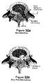
- An apertureis created measuring approximately, for example, 6 mm ⁇ 2 mm in the wall of the annulus after performing a discectomy procedure in which a portion of the nucleus is also removed from the disc space, as shown in FIGS. 32 a , 32 b , 33 a and 33 b.
- a piece of para-spinal fascial tissueis removed from the patient measuring approximately, for example, 10 mm ⁇ 5 mm.
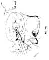
- the autograftis folded and compressed to pass through the aperture in the annulus, as shown for example in FIG. 35
- the autografttakes a second shape, within the annulus that is uncompressed and oriented to be in proximity of the subannular wall of the annulus, within the sling, as shown for example in FIG. 36 .
- the autograftmay be inserted entirely into the subannular space, or a portion may extend into the rent as depicted in FIG. 36 .
- the suturesare tightened, as shown for example in FIG. 37 , thus tightening the sling surrounding the autograft, to bring the autograft in close proximity with the subannular wall, while providing tension to bring the patch at the subannular surface together with the outer surface of the annular wall, thus creating increased integrity of the annulus surrounding the aperture, as well as causing the autograft to take a second shape that is larger than the aperture. Furthermore, the tightening, and eventual tying of the sutures also promotes the re-approximation of the tissue at the outer surface of the annulus and within the aperture.
- the suturesare tied and the ends of the sutures are cut.
- a piece of autograft fat tissuemay be placed over the discectomy site for the prevention of adhesion formation, a typical surgical technique.
- Standard surgical techniquesare utilized to close the access site of the surgical procedures.
- an expandable devicesuch as for example, a patch/stent (note: patch, stent and device are used interchangeably) that has, in use, at least a portion of the device in proximity to the sub-annular space of the intervertebral disc annulus; a means to affix the patch to stay in proximity with the annulus; a means to draw the patch and the annular tissue together and fasten in tension; and a means to help reduce the relative motion of the surfaces of the aperture after fixation, and thus promote healing.
- close approximation of tissue, while reducing the motion of the surfacesprovides the optimal environment for healing.
- one or more mild biodegradable surgical suturescan be placed at about equal distances along the sides of a pathologic aperture in the ruptured disc wall (annulus) or along the sides of a surgical incision in the annular wall, which may be weakened or thinned.
- Suturesare then tied in such fashion as to draw together the sides of the aperture, effecting reapproximation or closure of the opening, to enhance natural healing and subsequent reconstruction by natural tissue (fibroblasts) crossing the now surgically narrowed gap in the disc annulus.
- the methodcan be augmented by creating a subannular barrier in and across the aperture by placement of a patch of human muscle fascia (muscle connective tissue) or any other autograft, allograft, or xenograft acting as a bridge or a scaffold, providing a platform for traverse of fibroblasts or other normal cells of repair existing in and around the various layers of the disc annulus, prior to closure of the aperture.
- a patch of human muscle fasciamuscle connective tissue
- any other autograft, allograft, or xenograftacting as a bridge or a scaffold, providing a platform for traverse of fibroblasts or other normal cells of repair existing in and around the various layers of the disc annulus, prior to closure of the aperture.
- biocompatible membranescan be employed as a bridge, stent, patch or barrier to subsequent migration of the disc nucleus through the aperture.
- biocompatible materialsmay be, for example, medical grade biocompatible fabrics, biodegradable polymeric sheets, or form fitting or non-form fitting fillers for the cavity created by removal of a portion of the disc nucleus pulposus in the course of the disc fragment removal or discectomy.
- the prosthetic materialcan be placed in and around the intervertebral space, created by removal of the degenerated disc fragments.
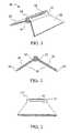
- FIG. 1shows a perspective view of an illustrative embodiment of an annulus stent.
- FIG. 2shows a front view of the annulus stent of FIG. 1 .
- FIG. 3shows a side view of the annulus stent of FIG. 1 .
- FIGS. 4A–4Cshow a front view of alternative illustrative embodiments of an annulus stent.
- FIGS. 5A–5Bshow the alternative embodiment of a further illustrative embodiment of an annulus stent.
- FIGS. 6A–6Bshow the alternative embodiment of a further illustrative embodiment of an annulus stent.
- FIG. 7shows a primary closure of an opening in the disc annulus.
- FIGS. 8A–8Bshow a primary closure with a stent.
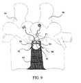
- FIG. 9shows a method of suturing an annulus stent into the disc annulus utilizing fixation points on vertebral bodies.
- FIGS. 10A–10Bshow a further illustrative embodiment of an annulus stent with flexible bladder being expanded into the disc annulus.
- FIGS. 11A–11Dshow an annulus stent being inserted into and expanded within the disc annulus.
- FIGS. 12A–12Bshow an annulus stent with a flexible bladder being expanded.
- FIG. 13shows a perspective view of a further illustrative embodiment of an annulus stent.
- FIG. 14shows a first collapsed view of the annulus stent of FIG. 13 .
- FIG. 15shows a second collapsed view of the annulus stent of FIG. 13 .
- FIGS. 16A–16Cshow the annulus stent of FIG. 13 being inserted into the disc annulus.
- FIGS. 17A–17Cshow a method of inserting the annulus stent of FIG. 13 into the disc annulus.
- FIGS. 18A–18Bshow a further illustrative embodiment of an annulus stent with a flexible bladder.
- FIGS. 19A–19Bshow another illustrative embodiment of an annulus stent with a flexible bladder.
- FIG. 20shows an expanded annulus stent with barbs on the radial extension.
- FIG. 21shows a still further illustrative embodiment of an annulus stent with a compressible core.
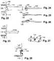
- FIG. 22shows a still further illustrative embodiment of an introduction device for an annulus stent.
- FIG. 23shows a modification of the device depicted in FIG. 22 .
- FIG. 24shows an exemplary introduction tool for use with the devices of FIGS. 22 and 23 with a stent deflected proximally.
- FIG. 25shows an exemplary introduction tool for use with the devices of FIGS. 22 and 23 with a stent deflected distally.
- FIG. 26shows an exemplary introduction tool for use with the devices of FIGS. 22 and 23 with a stent deflected partially distally and partially proximally.
- FIG. 27shows a still further illustrative embodiment of a stent device having a grasping feature and fixation devices in the form of barbs.
- FIG. 28shows the illustrative embodiment in FIG. 27 deployed subannularly.
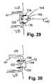
- FIG. 29shows a still further illustrative embodiment of an annulus stent employing a secondary barbed fixation device.
- FIG. 30shows a still further illustrative embodiment of an annulus stent employing another example of a secondary barbed fixation device.
- FIG. 31shows the frame of a still further illustrative embodiment of an annulus stent having a metal substrate being machined from flat stock.
- FIG. 32 ashows a herniated disc in perspective view
- FIG. 32 bshows the same disc after discectomy.
- FIG. 33 ashows a top view of the disc post-discectomy
- FIG. 33 bshows a posteriolateral view of the disk showing an incision.
- FIG. 34shows schematically the creation of a subannular sling using sutures.
- FIG. 35schematically shows the introduction of a compressed autograft stent/patch into the subannular space.
- FIG. 36schematically shows the autograft of FIG. 35 in an expanded shape within the annulus.
- FIG. 37schematically shows the tightening of the sutures to reapproximate the annulus aperture and draw the stent/patch of FIG. 35 toward the annular wall.
- FIG. 38shows an exemplary collar for use in repairing a disc annulus.
- FIG. 39schematically depicts the collar of FIG. 38 in use for disc annulus repair.
- FIG. 40shows a still further exemplary embodiment of the present invention using a bag to contain the patch/stent.
- FIGS. 41 a–eshow still further illustrative embodiments of the present invention having frames.
- FIG. 42shows an illustrative method for placing a barbed expandable patch in the subannular disc space.
- FIG. 43shows the patch of FIG. 42 being fixed to the inside wall of the annulus fibrosus.
- FIGS. 44 a–gshow a still further illustrative embodiment of an introduced and expanded annulus stent/patch being fixated and the aperture reapproximated.
- FIGS. 45 a–cschematically depict a still further embodiment of the present invention where an expandable stent/patch is tethered in situ using a cinch line.
- FIGS. 46 a–cschematically depict the cinch line of FIG. 45 being fixated through use of a surgical staple device.
- FIGS. 47 a–bshow an illustrative embodiment of a suturing arrangement for securing a patch/stent in the annulus.
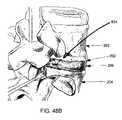
- FIGS. 48 a–bdepict a still further illustrative embodiment where fixation sutures are placed into the vertebral body or the Sharpey fibers.
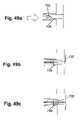
- FIGS. 49 a–cschematically depict a still further embodiment of the present invention where an expandable stent/patch is tethered in situ using a cinch line.
- FIGS. 50 a–cschematically depict the cinch line of FIG. 49 being fixated through use of a barbed surgical staple device that penetrates the patch/stent.
- FIG. 51depicts an exemplary use of filler tissue within the aperture during placement of a patch/stent tethered by a cinch line.
- FIGS. 52 a–eshows exemplary embodiments of various additional patch/stent fixation techniques.
- FIG. 53shows a still further illustrative embodiment of a stent/patch having a frame.
- FIGS. 54 a–fshows a still further illustrative embodiment of an annular stent/patch having a self-contained fixation tightening feature.
- FIG. 55shows a still further exemplary embodiment of the present invention having external fixation anchors.
- FIGS. 56 a–cshows a still further exemplary embodiment of the present invention having external fixation anchors.
- FIGS. 57 a–cshows a still further exemplary embodiment of the present invention having external fixation anchors.
- FIG. 58a–cshows a still further exemplary embodiment of the present invention having external fixation anchors.
- FIG. 59shows a still further exemplary embodiment of the present invention having a springing arrangement.
- a damaged annulus 42is repaired by use of surgical sutures 40 .
- One or more surgical sutures 40are placed at about equal distances along the sides of a pathologic aperture 44 in the annulus 42 .
- Reapproximation or closure of the aperture 44is accomplished by tying the sutures 40 so that the sides of the aperture 44 are drawn together.
- the reapproximation or closure of the aperture 44enhances the natural healing and subsequent reconstruction by the natural tissue (e.g., fibroblasts) crossing the now surgically narrowed gap in the annulus 42 .
- the surgical sutures 40are biodegradable, but permanent non- biodegradable may be utilized.
- a surgical incisioncan be made along the weakened or thinned region of the annulus 42 and one or more surgical sutures 40 can be placed at about equal distances laterally from the incision. Reapproximation or closure of the incision is accomplished by tying the sutures 40 so that the sides of the incision are drawn together. The reapproximation or closure of the incision enhances the natural healing and subsequent reconstruction by the natural tissue crossing the now surgically narrowed gap in the annulus 42 .
- the surgical sutures 40are biodegradable, but permanent non-biodegradable materials may be utilized.
- the methodcan be augmented by the placement of a patch of human muscle fascia or any other autograft, allograft or xenograft in and across the aperture 44 .
- the patchacts as a bridge in and across the aperture 44 , providing a platform for traverse of fibroblasts or other normal cells of repair existing in and around the various layers of the disc annulus 42 , prior to closure of the aperture 44 .
- a biocompatible membranecan be employed as an annulus stent 10 , being placed in and across the aperture 44 .
- the annulus stent 10acts as a bridge in and across the aperture 44 , providing a platform for a traverse of fibroblasts or other normal cells of repair existing in and around the various layers of the disc annulus 42 , prior to closure of the aperture 44 .
- the device, stent or patchcan act as a scaffold to assist in tissue growth that healingly scars the annulus.
- the annulus stent 10comprises a centralized vertical extension 12 , with an upper section 14 and a lower section 16 .
- the centralized vertical extension 12can be trapezoid in shape through the width and may be from about 8 mm–12 mm in length.
- the upper section 14 of the centralized vertical extension 12may be any number of different shapes, as shown in FIGS. 4A through 4C , with the sides of the upper section 14 being curved or with the upper section 14 being circular in shape.
- the annulus stent 10may contain a recess between the upper section 14 and the lower section 16 , enabling the annulus stent 10 to form a compatible fit with the edges of the aperture 44 .
- the upper section 14 of the centralized vertical extension 12can comprise a slot 18 , where the slot 18 forms an orifice through the upper section 14 .
- the slot 18is positioned within the upper section 14 such that it traverses the upper section's 14 longitudinal axis.
- the slot 18is of such a size and shape that sutures, tension bands, staples or any other type of fixation device known in the art may be passed through, to affix the annulus stent 10 to the disc annulus 42 .
- the upper section 14 of the centralized vertical extension 12may be perforated.
- the perforated upper section 14contains a plurality of holes that traverse the longitudinal axis of upper section 14 .
- the perforationsare of such a size and shape that sutures, tension bands, staples or any other type of fixation device known in the art may be passed through, to affix the annulus stent 10 to the disc annulus 42 .
- the lower section 16 of the centralized vertical extension 12can comprise a pair of lateral extensions, a left lateral extension 20 and a right lateral extension 22 .
- the lateral extensions 20 and 22comprise an inside edge 24 , an outside edge 26 , an upper surface 28 , and a lower surface 30 .
- the lateral extensions 20 and 22can have an essentially constant thickness throughout.
- the inside edge 24is attached to and is about the same length as the lower section 16 .
- the outside edge 26can be about 8 mm–16 mm in length.
- the inside edge 24 and the lower section 16meet to form a horizontal plane, essentially perpendicular to the centralized vertical extension 12 .
- the upper surface 28 of the lateral extensions 20 and 22can form an angle from about 0°–60° below the horizontal plane.
- the width of the annulus stent 10may be from about 3 mm–8 mm.
- the upper surface 28 of the lateral extensions 20 and 22may be barbed for fixation to the inside surface of the disc annulus 42 and to resist expulsion through the aperture 44 .
- the lateral extensions 20 and 22have a greater thickness at the inside edge 24 than at the outside edge 26 .
- the annulus stent 10is a solid unit, formed from one or more of the flexible resilient biocompatible or bioresorbable materials well know in the art.
- the selection of appropriate stent materialsmay be partially predicated on specific stent construction and the relative properties of the material such that, after fixed placement of the stent, the repair may act to enhance the healing process at the aperture by relatively stabilizing the tissue and reducing movement of the tissue surrounding the aperture.
- the annulus stent 10may be made from:
- ePTFEexpanded polytetrafluoroethylene
- vascular graftssuch as those sold by W.L. Gore and Associates, Inc. under the trademarks GORE-TEX and PRECLUDE, or by Impra, Inc. under the trademark IMPRA.
- annulus, stent 10may contain hygroscopic material for a controlled limited expansion of the annulus stent 10 to fill the evacuated disc space cavity.
- annulus stent 10may comprise materials to facilitate regeneration of disc tissue, such as bioactive silica-based materials that assist in regeneration of disc tissue as disclosed in U.S. Pat. No. 5,849,331 (Ducheyne, et al.), or other tissue growth factors well known in the art.
- the left and right lateral extensions 20 and 22join to form a solid pyramid or cone. Additionally, the left and right lateral extensions 20 and 22 may form a solid trapezoid, wedge, or bullet shape.
- the solid formationmay be a solid biocompatible or bioresorbable flexible material, allowing the lateral extensions 20 and 22 to be compressed for insertion into aperture 44 , then to expand conforming to the shape of the annulus' 42 inner wall.
- a compressible coremay be attached to the lower surface 30 of the lateral extensions 20 and 22 , forming a pyramid, cone, trapezoid, wedge, or bullet shape.
- the compressible coremay be made from one of the biocompatible or bioresorbable resilient foams well known in the art.
- the corecan also comprise a fluid-expandable membrane, e.g., a balloon.
- the compressible coreallows the lateral extensions 20 and 22 to be compressed for insertion into aperture 44 , then to expand conforming to the shape of the annulus' 42 inner wall and to the cavity created by pathologic extrusion or surgical removal of the disc fragment.
- the lateral extensions 20 and 22are compressed together for insertion into the aperture 44 of the disc annulus 42 .
- the annulus stent 10is then inserted into the aperture 44 , where the lateral extensions 20 , 22 expand.
- the upper surface 28can substantially conform to the contour of the inside surface of the disc annulus 42 .
- the upper section 14is positioned within the aperture 44 so that the annulus stent 10 may be secured to the disc annulus 42 , using means well known in the art.
- the annulus stent 10can be inserted laterally into the aperture 44 .
- the lateral extensions 20 and 22are compressed, and the annulus stent 10 can then be laterally inserted into the aperture 44 .
- the annulus stent 10can then be rotated inside the disc annulus 42 , such that the upper section 14 can be held back through the aperture 44 .
- the lateral extensions 20 and 22are then allowed to expand, with the upper surface 28 contouring to the inside surface of the disc annulus 42 .
- the upper section 14can be positioned within, or proximate to, the aperture 44 in the subannular space such that the annulus stent 10 may be secured to the disc annulus, using means well known in the art.
- a first surgical screw 50 and second surgical screw 52are inserted into the vertebral bodies, illustratively depicted as adjacent vertebrae 54 and 56 .
- a suture 40is passed down though the disc annulus 42 , adjacent to the aperture 44 , through the eye hole 53 on the first screw 50 then back up through the disc annulus 42 and through the orifice 18 on the annulus stent 10 . This is repeated for the second screw 52 , after which the suture 40 is secured.
- One or more surgical sutures 40are placed at about equal distances along the sides of the aperture 44 in the disc annulus 42 .
- Reapproximation or closure of the aperture 44is accomplished by tying the sutures 40 in such a fashion that the sides of the aperture 44 are drawn together.
- the reapproximation or closure of the aperture 44enhances the natural healing and subsequent reconstruction by the natural tissue crossing the now surgically narrowed gap in the annulus 42 .
- the surgical sutures 40are biodegradable but permanent non-biodegradable forms may be utilized. This method should decrease the strain on the disc annulus 42 adjacent to the aperture 44 , precluding the tearing of the sutures through the disc annulus 42 .
- a flexible bladder 60is attached to the lower surface 30 of the annulus stent 10 .
- the flexible bladder 60comprises an internal cavity 62 surrounded by a membrane 64 , where the membrane 64 is made from a thin flexible biocompatible material.
- the flexible bladder 60is attached to the lower surface 30 of the annulus stent 10 in an unexpanded condition.
- the flexible bladder 60is expanded by injecting a biocompatible fluid or expansive foam, as known in the art, into the internal cavity 62 .
- the exact size of the flexible bladder 60can be varied for different individuals. The typical size of an adult nucleus is about 2 cm in the semi-minor axis, 4 cm in the semi-major axis, and 1.2 cm in thickness.
- the membrane 64is made of a semi-permeable biocompatible material.
- the mechanical properties of the injectate materialmay influence the performance of the repair and it is contemplated that materials which are “softer” or more compliant as well as materials that are less soft and less compliant than healthy nucleus are contemplated within the scope of certain embodiments of the invention. It must be understood that in certain embodiments the volume added to the subannular space may be less than equal to or larger than the nucleus volume removed. The volume of the implant may vary over time as well in certain embodiments.
- a hydrogelis injected into the internal cavity 62 of the flexible bladder 60 .
- a hydrogelis a substance formed when an organic polymer (natural or synthetic) is cross-linked via, covalent, ionic, or hydrogen bonds to create a three-dimensional open-lattice structure, which entraps water molecules to form a gel.
- the hydrogelmay be used in either the hydrated or dehydrated form.
- an injection instrumentas known in the art, such as a syringe, is used to inject the biocompatible fluid or expansive foam into the internal cavity 62 of the flexible bladder 60 .
- the biocompatible fluid or expansive foamis injected through the annulus stent 10 into the internal cavity 62 of the flexible bladder 60 .
- Sufficient materialis injected into the internal cavity 62 to expand the flexible bladder 60 to fill the void in the intervertebral disc cavity.
- the use of the flexible bladder 60is particularly useful when it is required to remove all or part of the intervertebral disc nucleus.
- the surgical repair of an intervertebral discmay require the removal of the entire disc nucleus, being replaced with an implant, or the removal of a portion of the disc nucleus thereby leaving a void in the intervertebral disc cavity.
- the flexible bladder 60allows for the removal of only the damaged section of the disc nucleus, with the expanded flexible bladder 60 filling the resultant void in the intervertebral disc cavity.
- a major advantage of the annulus stent 10 with the flexible bladder 60is that the incision area in the annulus 42 can be reduced in size, as there is no need for the insertion of an implant into the intervertebral disc cavity.
- a dehydrated hydrogelis injected into the internal cavity 62 of the flexible bladder 60 .
- Fluid, from the disc nucleus,passes through the semipermeable membrane 64 hydrating the dehydrated hydrogel.
- the hydrogelabsorbs the fluid the flexible bladder 60 expands, filling the void in the intervertebral disc cavity.
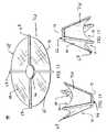
- the annulus stent 10is substantially umbrella shaped, having a central hub 66 with radially extending struts 67 .
- Each of the struts 67is joined to the adjacent struts 67 by a webbing material 65 , forming a radial extension 76 about the central hub 66 .
- the radial extension 76has an upper surface 68 and a lower surface 70 , where the upper surface 68 contours to the shape of the disc annulus' 42 inner wall when inserted as shown in FIGS. 17A–C , and where the lower surface 70 contours to the shape of the disc annulus' 42 inner wall when inserted as shown in FIGS. 16A–C .
- the radial extension 76may be substantially circular, elliptical, or rectangular in plan shape. Additionally, as shown in FIG. 20 , the upper surface 68 of the radial extension 76 may be barbed 82 for fixation to the disc annulus' 42 inner wall and to resist expulsion through the aperture 42 .
- the struts 67are formed from flexible material, allowing the radial extension 76 to be collapsed for insertion into aperture 44 , then the expand conforming to the shape of the inner wall of disc annulus 42 .
- the annulus stent 10is substantially frustoconical or shuttlecock shaped, and having a first end 72 , comprising the central hub 66 , and a second end 74 .
- the radial extension 76has a greater thickness at the central hub 66 edge than at the outside edge.
- the annulus stent 10is a solid unit, formed from one or more of the flexible resilient biocompatible or bioresorbable materials well known in the art.
- annulus stent 10may comprise materials to facilitate regeneration of disc tissue, such as bioactive silica based materials that assist in regeneration of disc tissue as disclosed in U.S. Pat. No. 5,849,331 (Ducheyne, et al.), or other tissue growth factors well known in the art.
- a compressible core 84may be attached to the lower surface 70 of the radial extension 76 .
- the compressible core 84may be made from one of the biocompatible or bioresorbable resilient foams well known in the art.
- the compressible core 84allows the radial extension 76 to be compressed for insertion into aperture 44 then to expand conforming to the shape of the disc annulus' 42 inner wall and to the cavity created by pathologic extrusion or surgical removal of the disc fragment.
- a flexible bladder 80is attached to the lower surface 70 of the annulus stent 10 .
- the flexible bladder 80comprises an internal cavity 86 surrounded by a membrane 88 , where the membrane 88 is made from a thin flexible biocompatible material.
- the flexible bladder 86is attached to the lower surface 70 of the annulus stent 10 in an unexpanded condition.
- the flexible bladder 80is expanded by injecting a biocompatible fluid or expansive foam, as known in the art, into the internal cavity 86 .
- the exact size of the flexible bladder 80can be varied for different individuals. The typical size of an adult nucleus is 2 cm in the semi-minor axis, 4 cm in the semi-major axis and 1.2 cm in thickness.
- the membrane 88is made of a semi-permeable biocompatible material.
- the radial extension 76is collapsed together, for insertion into the aperture 44 of the disc annulus 42 .
- the radial extension 76is folded such the upper surface 68 forms the outer surface of the cylinder.
- the annulus stent 10is then inserted into the aperture 44 , inserting the leading end 72 though the aperture 44 until the entire annulus stent 10 is within the disc annulus 42 .
- the radial extension 76is released, expanding within the disc 44 .
- the lower surface 70 of the annulus stent 10contours to the inner wall of disc annulus 42 .
- the central hub 66is positioned within the aperture 44 so that the annulus stent 10 may be secured to the disc annulus 42 using means well known in the art.
- the radial extension 76is collapsed together for insertion into the aperture 44 of the disc annulus 42 .
- the radial extension 76is folded such that the upper surface 68 forms the outer surface of the stent, for example in a frustoconical configuration as illustrated.
- the annulus stent 10is then inserted into the aperture 44 , inserting the tail end 74 through the aperture 44 until the entire annulus stent 10 is in the disc.
- the radial extension 76is released, expanding within the disc.
- the upper surface 68 of the annulus stent 10contours to the disc annulus' 42 inner wall.
- the central hub 66is positioned within the aperture 44 so that the annulus stent 10 may be secured to the disc annulus 42 , using means well known in the art.
- the barbs 82 on the upper surface 68 of one or more strut 67 or other feature of the radial extension 76engage the disc annulus' 42 inner wall, holding the annulus stent 10 in position.
- an injection instrumentas known in the art, such as a syringe, can be used to inject the biocompatible fluid or expansive foam into the internal cavity 86 of the flexible bladder 80 .
- the biocompatible fluid or expansive foamis injected through the annulus stent 10 into the internal cavity 86 of the flexible bladder 80 .
- Sufficient materialis injected into the internal cavity 86 to expand the flexible bladder 80 to fill the void in the intervertebral disc cavity.
- the materialcan be curable (i.e., glue).
- the use of the flexible bladder 80is particularly useful when it is required to remove all or part of the intervertebral disc nucleus.
- one wall or barriercan be made stiffer and less resilient than others. This relatively stiff wall member can then be placed proximate the annulus wall and can advantageously promote, in addition to its reparative properties, bag containment within the annulus.
- FIG. 22shows a further aspect of the present invention.
- a simplified schematic cross section of a vertebral pairis depicted including an upper vertebral body 110 , a lower vertebral body 112 and an intervertebral disc 114 .
- An aperture or rent 116 in the annulus fibrosus (AF)is approached by a tube 118 , which is used to deliver a device 120 according to a further aspect of the present invention.
- the device 120may be captured by a delivery tool 122 through the use of a ring or other fixation feature 124 mounted on the repair device 120 .
- FIG. 23shows a delivery method similar to that depicted in FIG. 22 , with the exception that the tube 118 A has a reduced diameter so that it may enter into the sub-annular space of the disc 114 through the aperture or rent.
- the delivery of the device 120 through the delivery tube 118 or 118 Amay be facilitated by folding the arms or lateral extensions 128 , 130 of the device to fit within the lumen of the tube 118 or 118 A so that the stent or device 120 is introduced in a collapsed configuration.
- the device 120is moved through the lumen of the tubes 118 or 118 A through the use of delivery tool 122 .
- FIG. 25shows the arms deflected in a distal, or forward direction for insertion into the delivery tube 118 or 118 A while FIG. 24 shows the arms 128 , 130 deflected into a proximal position.
- FIG. 25shows the arms deflected in a distal, or forward direction for insertion into the delivery tube 118 or 118 A while FIG. 24 shows the arms 128 , 130 deflected into a proximal position.
- 26shows the device 120 curled so that one arm 128 is projecting distally, or in a forward direction, and the other arm 130 is projecting proximally, or in a rearward direction. Because the lateral extent of the device is relatively flexible, whether the device is of natural or synthetic material, other collapsible configurations consistent with the intent of this invention are also possible, including twisting, balling, crushing, etc.
- FIG. 27shows the device 120 having a series of peripheral barb structures typified by barb 132 located at the edges. In operation, these barbs may be forced into the annulus fibrosus as seen in connection with FIG. 28 .
- Barb placementcan be anywhere on the device 120 provided that at least some number of barbs are likely to find annulus fibrosus tissue to anchor in during placement. For a simple aperture or rent, placement on the periphery of the device body is a reasonable choice, but for complex tears, it may be desirable to place a plurality of barbs on the device not knowing in advance which barbs will find tissue to anchor in during placement.
- FIG. 29shows an alternative fixation strategy where a pair of barbs 134 and 136 are plunged into the annulus fibrosus from the exterior of the annulus while the device 120 is retained in the sub-annular space by means of a tether 142 .
- a tether 142may be knotted 145 with the band 144 holding the barbs 134 and 136 together to fix the device in the sub-annular space. The knot is shown in an uncinched position to clarify the relationship between the tether 142 and the bands 144 .
- the devicecan be maintained in a subannular position by the barbed bands while the tether knot is cinched, advantageously simultaneously reapproximating the annulus to close the aperture while drawing the device into sealing, bridging engagement with the subannular wall of the annulus fibrosus.
- FIG. 30shows an alternative fixation strategy where the barbs 148 and 150 are sufficiently long that they can pierce the body of the device 120 and extend all the way through the annulus fibrosus into the device 120 .
- the band 144 connecting the barbs 148 and 150may be tightened to gently restrain and position the device 120 in the subannular space, or tightened with greater force to reapproximate the aperture or rent.
- FIG. 31shows a still further illustrative embodiment according to another aspect of the present invention.
- a metal substrate 160is incorporated into the device 120 .
- This piececan be machined from flat stock and includes the loop 162 as well as barbs typified by barb 164 .
- the structure shown in FIG. 31is used in a manner analogous to FIG. 27 and FIG. 28 .
- Stentscan expand to be planar, for example as shown hereinabove in FIGS. 4 , 8 , 9 , 11 and 12 , or they can expand to be three-dimensional as shown hereinabove in FIGS. 5 and 10 .
- FIG. 34shows the superior vertebral body 202 and the inferior vertebral body 204 surrounding a disc having an annulus fibrosus 206 and nucleus pulposus 203 in the subannular space.
- a suture 210is passed from outside the annulus through the wall of the annulus on one side of an aperture 208 and into the subannular space as shown. The suture is then passed back out through the annular wall on an opposing side of the aperture 208 leaving a loop or sling 212 of suture in the subannular space. As shown in the posterior view on the right side of FIG. 34 , more than one suture can be applied.
- a fascial autograft 214is then inserted through the aperture 208 into the subannular space using, for example, forceps 216 .
- FIG. 36shows the fascial stent/patch 214 fully inserted into the subannular space within the suture sling 212 .
- the closure of the apertureis accomplished simultaneously with pulling the autograft 214 toward the annular wall as shown in FIG. 37 .
- the suture 210can be cinched 218 or tied to maintain the closure and the fixation of the patch/stent.
- Patchescan be folded and expanded in a single plane or in three dimensions. As shown in FIGS. 24–25 and 41 for example, collapsing the patch can be accomplished laterally, whether the device is a single material or composite. Other embodiments, such as that shown in FIG. 1 can collapse vertically, and still others such as that shown in FIG. 26 , longitudinally. Others can collapse in three dimensions, such as those shown in FIGS. 13–15 and 36 . Devices which expand in three dimensions can be packaged in a restraining jacket, such as a gelatine shell or “gelcap” for example, or a mesh of biosorbable or dissolvable material, that would allow for facile placement and subsequent expansion.
- a restraining jacketsuch as a gelatine shell or “gelcap” for example, or a mesh of biosorbable or dissolvable material, that would allow for facile placement and subsequent expansion.
- Patchescan also be constructed of a single component, as shown for example in FIG. 36 , made of autograft or a synthetic material such as Dacron, or for example where the stent is a gelcap. They can be made of multiple components.
- An exemplary stent(not shown) can be made from a polymeric material, for example silicone rubber, which can be formed to have a natural unstressed shape, for example that of a “Bulb”.
- a stylet or push-rodcan, for example, be inserted on the inside of the bulb to stretch the bulb into a second shape which is thinner and elongated. The second shape is sufficient to place within the aperture in the annulus.
- the push-rodUpon placement of the device within the sub-annular space, the push-rod is removed and the bulb assumes it natural, unstressed state, assuming a larger dimension within the sub-annular space.
- siliconeis used in this example, other metallic constructs could also be envisioned such as a Nitinol braided device that has a natural unstressed shape and assumes a second shape under tension for the delivery of the device. It is also contemplated that the opposite scenario can also accomplish the similar objective.
- the devicecan have a first configuration that is unstressed and elongated and assumes a second, larger configuration (bulb) under stress.
- a portion of the stylet or rod that is used to mechanically activate the devicewould be left behind to hold the expansion element in its stressed configuration.
- Multiple componentscould include a frame to help with expansion of the device and a covering to obtain biocompatibility and tissue ingrowth.
- frame configurationsmight include an expandable “Butterfly” or “Figure-8” configuration that could be constructed of wire material, such as Nitinol or multiple wires.
- Exemplary embodiments showing frame members 502are depicted in FIGS. 41A–E .
- Other configurationssuch as diamonds or other rounded or polygonal shapes can be used.
- the diamond frameis a construct that takes a first form that is smaller and expands to a larger frame.
- the diamond elementscould be constructed from a single wire or from multiple wires.
- the memberscould be constructed of elements that are moveable fixed at each of the ends to allow expansion.
- a tether or attachment device 504is also depicted, which may be a suture, a wire, a screw, or other attachment means known in the art.
- the framecould be cut from a single material, such as flat stock Nitinol to accomplish the same objective, as shown for example in FIG. 31 .
- Such shapescan be cut from flat stock using known methods, for example, laser cutting.
- a heat forming stepcould also be employed, as known in the art, to form barbs 132 in a shape that passes out of the flat plane of the stock material, as shown in FIG. 27 for example.
- Another frame configurationis that of a spiral or coil.
- the “Coil” designcan be, for example, a spring steel or other biocompatible material that is wrapped to a first “wound” smaller configuration and expands to a larger unwrapped, unwound configuration.
- each of these conceptsmay or may not have a covering over them in order to assure that the nucleus does not re-extrude from the intervertebral disc space after placement of the device, as well as to serve as substrate for the surrounding tissue to naturally incorporate the device.
- Coveringsmight include ePTFE, polyester, silicone, or other biocompatible materials. Coverings could also include natural materials such as collagen, cellulose, autograft, xenograft, allograft or similar materials. The covering could also be biodegradable in nature, such as polyvinyl lactic acid.
- Frames that are not coveredmay be permeable, such as a patch that is porous and allow for normal movement of fluids and nutrients through the patch into and out of the annular ring while maintaining nucleus fragments larger than the porosity of the stent/patch within the subannular space.
- a surface finishmay be added to promote tissue ingrowth into the patch.
- a titanium sputtering of the devicemay allow it to be more easily incorporated within the disc space.
- a NiTi or tantalum foamcould be added to the outer surface of the patch to promote tissue ingrowth.
- the stent/patch according to the present inventionmay comprise a mass of fascial autograft, and that autograft may be contained in a covering of material to form what will be referred to herein as a “bag”.
- this termis used not necessarily to connote a five-sided closed container so much as to denote the notion of flexibly surrounding the volume of a patch/stent material so that it can be manipulated in space.
- a prefabricated device of suturescould be used to form the “sling” to hold the fascial implant as discussed above.
- the advantage of this design over simple placement of sutures to hold the autograftis better containment and control of the autograft during and after implantation.
- the “sling” or a “bag”surrounds the fascial autograft to hold it in place. It is contemplated that other materials, such as a polyester mesh, could be used instead of the fascial autograft.
- FIG. 38shows an example of a pre-fabricated sling 300 .
- a collar member 308has apertures or other features for attaching to the sutures.
- the third suture 306passes along or within the collar 308 to form a loop extending from the lateral extent of the collar 308 .
- the first and second sutures 302 , 304form loops from the superior and inferior extents of the collar 308 .
- Intersections 310can secure the loops to each other with small loops or knots in the sutures, small fabric attachment pieces, or by small preformed devices resembling grommets placed on the suture to aid in securement. Other knot tying techniques known in the art can also be employed.
- FIG. 39the collar is depicted within the subannular space where the loops surround a fascial autograft 314 which by pulling proximally the sutures 302 , 304 , 306 the graft is collapsed into contact with the annular wall in a sealing manner.
- the suturescan be made of known materials, e.g., biodegradable, bioabsorbable or bioresorbable Vicryl or biocompatible nylon.
- the collarcan be made of a fabric material, e.g., polyester.
- a fabric materiale.g., polyester.
- one end of some or each suturecan be passed through the inferior wall of the annulus and the other end can be passed through the superior wall surrounding the aperture.
- the fascial autograftis placed within the sling. The sutures are tightened to bring the tissues together and also to help reapproximate the aperture, as the collar size will be selected based on the surgeon's Judgment according to the degree of reapproximation desired.
- FIG. 40Other constructions can also be used to accomplish the same objective, such as a “bag” 404 formed of expandable PTFE as shown in FIG. 40 .
- the bagis placed through an aperture in the annulus 402 .
- a one way seal 406can be positioned behind the aperture 408 . Suturing techniques for introducing cardiac valves could be employed to place the seal. It is understood that there could be multiple constructs to accomplish the same objective and this is only given as an example.
- FIG. 20also depicts the use of “barbs” on the surface of the stent to facilitate fixation to the annulus. In a simple example, as shown in FIG.
- a patch/stentcould be compressed, passed through a guide tube such as tubes 18 , 18 A shown in FIGS. 22 and 23 , and expanded within the sub-annular space.
- a guide tubesuch as tubes 18 , 18 A shown in FIGS. 22 and 23
- the expanded patch 602is shown having barbs 604 , along with detachable delivery tool 608 and guide tube 606 .
- barbs 604 on the outer surface of patch 602can be used to fix the patch into the inner wall 610 of the annulus 612 by pulling the patch back proximally, into the sub-annular wall 610 , and pushing forward distally on the guide tube 606 , thus driving the barbs 604 into the annulus and drawing the inner and outer tissues of the annulus together and reapproximating the disc on either side of the aperture, as shown in FIG. 43 .
- the delivery tool and guide tubeare removed.
- Anchoring barbscould be made of a biocompatible material, for example a metallic material (e.g., NiTi alloy, Stainless steel, Titanium), or a polymeric material (e.g., polypropylene, polyethylene, polyurethane).
- Anchoring barbscould also be a biodegradable/bioabsorbable material, such as a polyglycolic acid (PGA), a polylevolactic acid (PPLA), a polydioxanone (PDA) or for example a racemic polylactic acid (PDLLA).
- PGApolyglycolic acid
- PPLApolylevolactic acid
- PDApolydioxanone
- PDLLAracemic polylactic acid
- the barbsincluded a biodegradable/bioabsorbable material, it is anticipated that the barbs might have sufficient holding strength for a sufficient period of time to allow the patch to be incorporated into the annulus during the healing process.
- the advantage of having the anchoring barb of FIGS. 42 and 43 being biodegradable/bioabsorbableis that after the incorporation of the patch into the annulus there may be no need for the barbs to provide fixation.
- barbs pointing toward the outer surface of the annuluscould pose a long term risk of penetration out of the annulus due to migration, and potentially impinging on the nerve root and spinal canal.
- Biodegradable/bioabsorbable barbsaddress and advantageously reduce any long-term risk in this regard.
- the barbscould be made of both a biocompatible component and a biodegradable/bioabsorbable component.
- the very tip of the barbcould be made of a biodegradable material.
- the barbcould penetrate the annulus wall with a rather sharp point, but after degradation the point of the barb would become dull. In this embodiment, the point would no longer induce continued scar formation after the patch has been incorporated, nor pose a risk of penetrating out of the annulus onto the nerve root.
- Another fixation meansincludes the passing of “anchoring bands” into the wall of the annulus, vertebral bodies (superior, inferior, or both), or the Sharpey's Fibers (collagenous fibers between the junction of the annular fibers and vertebral bodies).
- anchorsthe barbs or bands are affixed to the annulus/vertebral bodies/Sharpey's fibers.
- Another elementfor example a suture, cinch line, or a staple is utilized to attach the anchor bands to the patch, and thus hold the patch in proximity to the inner wall of the annulus.
- these bandsmay re-approximate the tissues at the aperture.
- FIG. 9Revisiting one example of using barbs to anchor the device is shown in FIG. 9 , described hereinabove.
- Barbs or bone anchor screws 50 ands 52are passed into the superior and inferior vertebral bodies 54 and 56 , respectively.
- Superiorly, suture 40is passed through the outer wall of the annulus, to the sub-annular space.
- the sutureis then passed through the eyelet 53 of bone anchor 52 and then passed through the wall of the annulus from the sub-annular space to the outer wall of the annulus.
- the inferior end of the sutureis similarly passed through the annulus, eyelet of the bone anchor, and back through the wall of the annulus. Both tends of suture 40 are tightened and tied.
- the advantage of this conceptis that it allows for fixation of the device to a surface that is known to be present in all discectomy procedures—the vertebral bodies. Whereas, it is possible, depending on the location and size of a natural rent that there may not be sufficient annulus accessible to fixate the device directly to the annulus. In addition to providing a location for fixation, anchoring into the vertebral bodies may provide a more stable anchor surface.
- FIG. 29Another example of fixating the device to inner wall of the annulus is shown in FIG. 29 , and is further illustrated by FIGS. 44–47 .
- a patch 120is placed with a delivery tool 122 , through the inner lumen of a guide tube 118 , into the sub-annular space and then expanded. This step can also be seen in FIGS. 45 and 46 , where a patch 702 is folded and passed through a guide tube 706 and is held by a delivery tool 704 .
- a anchor band or staple 709 and an anchor band delivery device 708are also shown.
- a suture line or cinch line 710that is attached to the center of the patch 702 .
- FIG. 44 aWith the guide tube 706 removed.
- the guide tube 706is retracted after the patch 702 has been expanded and deployed.
- an anchor band delivery tool 708is used to deliver one or more “bands” 709 onto the outer surface of the annulus. These are intended to be anchored into the wall of the annulus with barb shapes that do not allow for the barbs to be pulled back through the annulus.
- the anchor bandsresemble a construction of a “staple”.
- the bandscould actually be constructed by connecting two barbed elements with, for example, a suture between the two barbed elements.
- the barbs and the connection band between the barbscould be constructed of the same material or of different materials.
- the barbed part of the anchor bandcould be a biodegradable/bioabsorbable material (such as polyglycolic acid) or could be constructed of a metallic or polymeric biocompatible material (e.g., titanium, NiTi alloy, stainless steel, polyurethane, polypropylene).
- the band that connects these barbscan be constructed of materials that are similar to the barbs, or different materials.
- connection bandcould be a biodegradable/bioabsorbable suture, such as Vicryl, or a biocompatible material such as polypropylene.
- these elementsare constructed from multiple materials to accomplish the objective of anchoring into the annulus and providing for a fixation site to draw the patch within proximity of the sub-annular wall.
- FIGS. 44B and 44Cshow the placement of the anchor bands 709 into the annulus 712 with the anchor band delivery tool 708 .
- FIGS. 46A and 46Bschematically show the placement of the anchor bands 709 into the wall of the annulus 712 and the retraction of the anchor band delivery device 708 , with the patch delivery tool 704 still in place.
- FIG. 44Ddepicts a representative anchor band 709 , having a pair of stainless steel barbs 709 ′′ connected by a suture 709 ′.
- FIG. 44Eshows the patch 702 , anchor bands 709 , and cinch line or suture 710 with the delivery tools removed, prior to drawing the patch and the tissues of the annulus together.
- FIG. 47 aalso shows a posterior view of the patching of the annulus with this device with knot 714 .
- this stent/patch 702a pair of loops of 7 mm suture 709 are shown, which engage the cinch line and slip knot. These suture loops connect to the barbs directly, as in FIG. 44 , or loop to surgical staples, or are placed directly into the annulus.
- the presence of a pre-fabricated knot on the cinch linemakes the process of repairing quicker since there is no need to tie a knot. It also facilitates drawing the tissues together.
- FIG. 44Eis similar to the FIG. 29 described hereinabove prior to “tying” the knot 145 .
- FIG. 44Fshows the drawing of the patch and the annular tissues together by pulling on the suture in the direction “A” indicated by the arrow.
- the Knot Pusherhas been removed from the cinch line 710 .
- the suture 710is drawn proximally to draw the patch 702 into engagement with the inner wall of the annulus to seal the aperture from within, as well as draw the walls of the annulus together to reapproximate the annular aperture.
- 44Gshow the cinch line suture 710 tied and drawing the annular tissues together, after the excess suture line has been cut. It is also apparent from this device, fixation and delivery system that the outer surfaces of the aperture are also drawn together for re-approximation.
- the cinching of the bands and the patchalso allows for taking-up the slack that allows for the accommodation of varying sizes.
- the thickness of the annular wall surrounding the aperturecan vary from 1 mm up to 10 mm. Therefore, if the anchor bands have a set length, this design with an cinch line accommodates different dimensions of the thickness of the wall of the annulus by drawing the “slack” of the bands together within the aperture.
- the patch depicted in the example abovedoes not have barbs attached to the patch, it is also possible to have the barbs as described hereinabove to further promote the fixation of the patch to the inner wall of the annulus.
- FIG. 51shows the illustrative filling of an aperture with implant material 716 prior to cinching the suture 710 .
- the anchor bands 709 as described previouslycould be sufficiently long enough to pass through the annulus and then through the patch.
- the barbs in this embodimenthave an engaging involvement with the patch. This concept was previously discussed hereinabove in connection with FIG. 30 . Further illustration of such a system is schematically shown in FIGS. 49 and 50 . Passing the barbs through the patch, in this embodiment, provides additional security and safety of reducing the possibility that the barbs may migrate after implantation.
- the suture cinch linemay ( FIG. 50 ) or may not ( FIG. 30 ) be used in addition to the anchor bands to draw the tissues together and reduce tissue movement surrounding the aperture.
- the bands shown in FIGS. 49 and 50take the form of a “barb”, they could as easily take a form of a simple T-barb 720 , as shown in FIG. 52E , or a C-type element wherein the object is to have irrevocable engagement with the patch device 702 after the penetration through the patch.
- a T-type attachmentwhen aligned longitudinally with the suture, passes through the patch. The T section then rotates to prevent the suture anchor from being pulled back through the patch.
- a “C” retainermade of a superelastic material may be attached to the end of the suture band. The C retainer is loaded into a needle wherein it is held straight. The needle is used to pass the C retainer and suture through the patch and deploy the retainer in a second configuration in the shape of a “C”.
- patch designswhich will accommodate the placement and securement of the anchor to the fabric that covers the frame of the patch.
- a frame for a patch that is made out of metal such as Nitinolcan provide for “windows”.
- the device, covered with a mesh fabric, for example silicone or Dacron,would therefore allow the anchoring barbs to be passed through the “windows” in the frame of the patch. In this case, the barb can be secured to the patch in the fabric covering the frame.
- the patchcan be secured by passing barbs that engage the lattice of the patch frame.
- barbsthat engage the lattice of the patch frame.
- These embodiments of the inventionillustrate designs in which the barbs engage with the vertical, horizontal or criss-crossed structures/members of the frame. In this case, the barbs would pass through the mesh or lattice of the frame and they would be unable to pass back out of the structure.
- anchor bandsthat are shown to be two anchors connected by a suture
- single barbs with suturesare placed and the sutures' ends, at the outer surface of the annulus, are tied after placement through the patch.
- One objective in the designs discussed hereinaboveis to provide a way to “pull up the slack” in a system to adjust the length of sutures and for anchor bands.
- a technique referred to as the “Lasso Cinch Knot”was developed as a means to draw the anchor bands together with a suture cinch line that is incorporated into the patch design.
- FIG. 53gives further description of the use of the Lasso embodiment.
- patch and frame constructsare used that incorporate the “barbs through the patch” design. Once the barbs have passed through the patch, an internal lasso 722 is drawn tight around the sutures of the anchor bands and thus draws the extra suture material within the patch.
- the internal lassogathers the sutures of the bands, and as the lasso is tightened, it cinches together the sutures of the bands and therefore tightens them and eliminates slack, bringing the patch/stent into closer or tighter engagement with the annulus wall.
- the patch in FIG. 53additionally provides for a diamond shape grid pattern, which advantageously provides a grid which will while allowing a probe or similar instrument to pass through with little resistance, provides resistance to a barb or other restraining feature on the instrument.
- the frame showncan be made from nitinol, and the locking and holding windows shown at the center of the figure would allow for rotation about the z-axis during placement.
- a slipknot technique using, for example a knot pusherwould aid in the loop pulling process by the lasso.
- the internal loop (lasso)can be tacked to the outside corners of the patch/stent, in order to hold the loop at the outer edges of the patch frame.
- the loopcan be pulled free from some or all of its tacked attachment points to the frame, to prevent deformation of the planar shape of the frame when cinching the lasso.
- the framecan be a composite structure or sandwich formed with some type of mesh fabric.
- the proximal mesh fabriccan be bonded fully to the patch frame, for example through the use of an adhesive, for instance a silicone.
- Adhesiveadvantageously, can fill the interstices of the grid pattern while allowing for easy probe penetration and protection of the suture lines. Protection of the suture lines is advantageous when the lasso is used to pull and bunch a group of band sutures together.
- sutures 710 ′can be preattached directly to a stent/patch. As shown in FIG. 52A several separate barbs 709 ′′′ into the annulus 712 can be directly attached to the patch 702 . Each “barb” of FIG. 52A can be independently placed into the annulus after the patch is deployed. This can be seen to be similar to the embodiment including barbs 709 ′′′′ of FIG. 55 .
- An alternative embodiment for securing a patch 902 and reapproximating a rentis providing each of the separate barbs with sutures having variable lengths as shown in FIG. 56 .
- Each independent suture barb 904is placed into the annulus 906 or into the patch 902 with the barb delivery tool 908 .
- all of the suture lines 910are drawn taught, by drawing on the free ends that exit the patch delivery tool 912 .
- a locking element 914 that uses a gasket 916 and threading mechanismis attached to the patch 902 and is used to tighten the gasket 916 around the distal ends of the sutures 910 .
- the patch delivery tool 912is removed and the extra suture length is cut.
- the gasket mechanismcould be a press-fit to accommodate the tightening of the sutures to the patch.
- the locking mechanismcan be as shown in FIG. 57 , although in this case the engagement of the locking element 914 ′ takes part on the patch. Pulling the suture 910 in the direction of arrow B will tighten and lockingly hold in tension to aid in securement and reapproximation.
- the adjustable length suture band between the two anchorsallows slack to be taken up between the anchors 916 .
- Two T-type anchorsare illustratively shown in this example, but multiple anchors of differing configurations could be used.
- the locking featurescan be included on the feature band, as depicted here, and allow for substantially one-way locking engagement with the anchor members. This adjustability advantageously promotes for the accommodation of varying thickness of the annulus from patient to patient.
- the suture slack in this embodimentmay be taken up to close the defect in the annulus and/or to shorten the band between anchors for a secondary cinching of multiple tensioned suture bands as described hereinabove.
- the cinch line and the Lasso conceptsin essence try to facilitate the reapproximation and drawing of tissues together in a fast and simple way.
- Other contemplated embodiments for “tension” elementsinclude using an elastic coupler as a part of the anchor band used to fixate the device.
- the elastic couplercan be expanded for placement, and upon release, can draw tension to pull the tissues together.
- the couplercould be made of a biocompatible metal or polymer, or could be constructed of a biodegradable/bioabsorbable material.
- an alternative embodiment to cause tension within the device and draw the tissues together after placement of the anchor bandsmight include an elastic band or band with a spring which one end can be attached to the anchor bands and the other end attached to the patch.
- the anchor bandsmight, in and of themselves may be made of an elastic band between the barbs, or may contain a spring element between the barbs. Such an embodiment can be made to resemble a so-called “Bobber Spring.”
- the elastic or resilient elementcould be made from a wide variety of metals, polymeric, or biodegradable/bioabsorbable material.
- FIG. 59describes an embodiment where the patch element 1002 takes the form of a mesh seal.
- the securementis effected by a hook having a barb element 1004 that penetrates the inner surface of the annulus 1006 , while the inner connection of the hook (barb) 1004 is attached to the patch in such a fashion as to add tension between the outer surface of the annulus and the inner surface in proximity to the patch, thus drawing the annular tissues together.
- the patch/stent 1002contains a spring ribbon element 1008 which can be formed from nitinol or other spring material. Hooks 1010 are then deployed to “grab” the annulus, either through penetration or through grasping into the aperture 1012 as shown.
- FIGS. 54 a–fshows another embodiment of a means to draw the suture lines together to cause tension between the inner and outer tissues of the annulus.
- Anchor bandsfor example T-barbs 720 ′ are placed through the annulus and the patch, and they are secured to the patch 702 .
- “Slack” in the suture of the anchor bandis “rotated” around a detachable portion of the delivery tool 704 ′ and a locking element, for example a screw configuration 724 as shown in the drawing, is used to lock the extra suture line in place affixed to threads 726 with the patch 702 .
- the delivery tool 704 ′is then removed.
- FIG. 58shows alternative embodiments for tightening “anchoring barbs” with different configurations of sutures and cinch lines.
- each independent barbhas a looped suture attached to it. Through each of these loops is passed a cinch line, which contains a knot. After placement of the barbs within the annulus, and possibly through the patch, the cinch line draws the loops of the barbs together.
- the advantage of this embodimentis that it allows for the independent placement of multiple barbs and the ability to draw all of them together.
- cinch lineshave been described as using a knot to “lock” the length of the suture, other mechanisms could also lock the length, as shown in FIG. 57 .
- the locking of the suture lengthis accomplished through a mechanical element located on the barb which engages with three dimensional elements attached to the suture line which mechanically press fit through the engagement element on the barb, thus locking the length of the suture line into place.
- FIG. 57 and FIG. 58depict the use of a single locking mechanism (e.g., knot on cinch line), it is conceivable that various designs could use more than one locking element to achieve the re-approximation and drawing together the tissue surrounding an aperture.
- a single locking mechanisme.g., knot on cinch line
- the body portions of the stentcould be made of NiTi alloy, plastics including polypropylene and polyethylene, stainless steel and other biocompatible metals, chromium cobalt alloy, or collagen.
- Webbing materialscan include silicone, collagen, ePTFE, DACRON, polyester, polypropylene, polyethylene, and other biocompatible materials and can be woven or non-woven.
- Membranesmight be fashioned of silicone, propylene, polyester, SURLYN, PEBAX, polyethylene, polyurethane or other biocompatible materials.
- Inflation fluids for membranescan include gases, liquids, foams, emulsions, and can be or contain bioactive materials and can also be for mechanical, biochemical and medicinal purposes.
- the stent body, webbing and/or membranecan be drug eluting or bioabsorbable, as known in the medical implant arts.
Landscapes
- Health & Medical Sciences (AREA)
- Engineering & Computer Science (AREA)
- Biomedical Technology (AREA)
- Orthopedic Medicine & Surgery (AREA)
- Transplantation (AREA)
- Neurology (AREA)
- Heart & Thoracic Surgery (AREA)
- Oral & Maxillofacial Surgery (AREA)
- Cardiology (AREA)
- Vascular Medicine (AREA)
- Life Sciences & Earth Sciences (AREA)
- Animal Behavior & Ethology (AREA)
- General Health & Medical Sciences (AREA)
- Public Health (AREA)
- Veterinary Medicine (AREA)
- Physical Education & Sports Medicine (AREA)
- Chemical & Material Sciences (AREA)
- Dispersion Chemistry (AREA)
- Prostheses (AREA)
Abstract
Description
Claims (11)
Priority Applications (29)
| Application Number | Priority Date | Filing Date | Title |
|---|---|---|---|
| US10/133,339US7052516B2 (en) | 1999-10-20 | 2002-04-29 | Spinal disc annulus reconstruction method and deformable spinal disc annulus stent |
| US10/352,981US20030153976A1 (en) | 1999-10-20 | 2003-01-29 | Spinal disc annulus reconstruction method and spinal disc annulus stent |
| US11/120,750US7615076B2 (en) | 1999-10-20 | 2005-05-03 | Method and apparatus for the treatment of the intervertebral disc annulus |
| US11/235,764US7935147B2 (en) | 1999-10-20 | 2005-09-26 | Method and apparatus for enhanced delivery of treatment device to the intervertebral disc annulus |
| US11/350,843US7828850B2 (en) | 1999-10-20 | 2006-02-10 | Methods and devices for spinal disc annulus reconstruction and repair |
| US11/386,642US8088165B2 (en) | 1999-10-20 | 2006-03-23 | Spinal disc annulus reconstruction method and deformable spinal disc annulus stent |
| US11/386,616US20060173545A1 (en) | 1999-10-20 | 2006-03-23 | Spinal disc annulus reconstruction method and deformable spinal disc annulus stent |
| US11/512,251US7846208B2 (en) | 1999-10-20 | 2006-08-30 | Spinal disc annulus reconstruction method and deformable spinal disc annulus stent |
| US11/527,903US8632590B2 (en) | 1999-10-20 | 2006-09-26 | Apparatus and methods for the treatment of the intervertebral disc |
| US11/556,878US7985257B2 (en) | 1999-10-20 | 2006-11-06 | Methods and devices for spinal disc annulus reconstruction and repair |
| US11/557,997US8034112B2 (en) | 1999-10-20 | 2006-11-09 | Spinal disc annulus reconstruction method and spinal disc annulus stent |
| US11/559,457US7922768B2 (en) | 1999-10-20 | 2006-11-14 | Spinal disc annulus reconstruction method and deformable spinal disc annulus stent |
| US11/608,480US7993405B2 (en) | 1999-10-20 | 2006-12-08 | Spinal disc annulus repair system and methods |
| US11/622,631US7951201B2 (en) | 1999-10-20 | 2007-01-12 | Method and apparatus for the treatment of the intervertebral disc annulus |
| US11/686,599US7749273B2 (en) | 1999-10-20 | 2007-03-15 | Method and apparatus for the treatment of the intervertebral disc annulus |
| US12/197,458US20090024216A1 (en) | 1999-10-20 | 2008-08-25 | Spinal disc annulus reconstruction method and spinal disc annulus stent |
| US12/247,675US20090036990A1 (en) | 1999-10-20 | 2008-10-08 | Method and Apparatus for the Treatment of the Intervertebral Disc Annulus |
| US12/247,637US7963992B2 (en) | 1999-10-20 | 2008-10-08 | Method and apparatus for the treatment of the intervertebral disc annulus |
| US12/247,687US8100914B2 (en) | 1999-10-20 | 2008-10-08 | Method and apparatus for the treatment of the intervertebral disc annulus |
| US12/247,652US20090157184A1 (en) | 1999-10-20 | 2008-10-08 | Method and Apparatus for the Treatment of the Intervertebral Disc Annulus |
| US12/247,704US20090030522A1 (en) | 1999-10-20 | 2008-10-08 | Method and Apparatus for the Treatment of the Intervertebral Disc Annulus |
| US12/251,295US8128698B2 (en) | 1999-10-20 | 2008-10-14 | Method and apparatus for the treatment of the intervertebral disc annulus |
| US12/255,839US20090043343A1 (en) | 1999-10-20 | 2008-10-22 | Method and Apparatus for Enhanced Delivery of Treatment Device to the Intervertebral Disc Annulus |
| US12/945,614US8556977B2 (en) | 1999-10-20 | 2010-11-12 | Tissue anchoring system and method |
| US13/086,695US20110190896A1 (en) | 1999-10-20 | 2011-04-14 | Apparatus for enhanced delivery of treatment device to the intervertebral disc annulus |
| US13/171,625US9114025B2 (en) | 1999-10-20 | 2011-06-29 | Methods and devices for spinal disc annulus reconstruction and repair |
| US13/355,926US9095442B2 (en) | 1999-10-20 | 2012-01-23 | Method and apparatus for the treatment of the intervertebral disc annulus |
| US14/144,017US9675347B2 (en) | 1999-10-20 | 2013-12-30 | Apparatus for the treatment of tissue |
| US15/620,491US20170340321A1 (en) | 1999-10-20 | 2017-06-12 | Apparatus for the treatment of tissue |
Applications Claiming Priority (6)
| Application Number | Priority Date | Filing Date | Title |
|---|---|---|---|
| US16071099P | 1999-10-20 | 1999-10-20 | |
| US48470600A | 2000-01-18 | 2000-01-18 | |
| US30910501P | 2001-07-31 | 2001-07-31 | |
| US09/947,078US6592625B2 (en) | 1999-10-20 | 2001-09-05 | Spinal disc annulus reconstruction method and spinal disc annulus stent |
| US10/075,615US20020123807A1 (en) | 1999-10-20 | 2002-02-15 | Spinal disc annulus reconstruction method and spinal disc annulus stent |
| US10/133,339US7052516B2 (en) | 1999-10-20 | 2002-04-29 | Spinal disc annulus reconstruction method and deformable spinal disc annulus stent |
Related Parent Applications (3)
| Application Number | Title | Priority Date | Filing Date |
|---|---|---|---|
| US09/947,078Continuation-In-PartUS6592625B2 (en) | 1999-10-20 | 2001-09-05 | Spinal disc annulus reconstruction method and spinal disc annulus stent |
| US10/075,615Continuation-In-PartUS20020123807A1 (en) | 1999-10-20 | 2002-02-15 | Spinal disc annulus reconstruction method and spinal disc annulus stent |
| US10/075,615ContinuationUS20020123807A1 (en) | 1999-10-20 | 2002-02-15 | Spinal disc annulus reconstruction method and spinal disc annulus stent |
Related Child Applications (6)
| Application Number | Title | Priority Date | Filing Date |
|---|---|---|---|
| US10352891Continuation-In-Part | |||
| US10/327,106Continuation-In-PartUS7004970B2 (en) | 1999-10-20 | 2002-12-24 | Methods and devices for spinal disc annulus reconstruction and repair |
| US10/327,106ContinuationUS7004970B2 (en) | 1999-10-20 | 2002-12-24 | Methods and devices for spinal disc annulus reconstruction and repair |
| US10/352,981Continuation-In-PartUS20030153976A1 (en) | 1999-10-20 | 2003-01-29 | Spinal disc annulus reconstruction method and spinal disc annulus stent |
| US11/386,642ContinuationUS8088165B2 (en) | 1999-10-20 | 2006-03-23 | Spinal disc annulus reconstruction method and deformable spinal disc annulus stent |
| US11/686,599Continuation-In-PartUS7749273B2 (en) | 1999-10-20 | 2007-03-15 | Method and apparatus for the treatment of the intervertebral disc annulus |
Publications (2)
| Publication Number | Publication Date |
|---|---|
| US20020189622A1 US20020189622A1 (en) | 2002-12-19 |
| US7052516B2true US7052516B2 (en) | 2006-05-30 |
Family
ID=46150119
Family Applications (4)
| Application Number | Title | Priority Date | Filing Date |
|---|---|---|---|
| US10/133,339Expired - LifetimeUS7052516B2 (en) | 1999-10-20 | 2002-04-29 | Spinal disc annulus reconstruction method and deformable spinal disc annulus stent |
| US11/386,642Expired - Fee RelatedUS8088165B2 (en) | 1999-10-20 | 2006-03-23 | Spinal disc annulus reconstruction method and deformable spinal disc annulus stent |
| US11/557,997Expired - Fee RelatedUS8034112B2 (en) | 1999-10-20 | 2006-11-09 | Spinal disc annulus reconstruction method and spinal disc annulus stent |
| US11/559,457Expired - Fee RelatedUS7922768B2 (en) | 1999-10-20 | 2006-11-14 | Spinal disc annulus reconstruction method and deformable spinal disc annulus stent |
Family Applications After (3)
| Application Number | Title | Priority Date | Filing Date |
|---|---|---|---|
| US11/386,642Expired - Fee RelatedUS8088165B2 (en) | 1999-10-20 | 2006-03-23 | Spinal disc annulus reconstruction method and deformable spinal disc annulus stent |
| US11/557,997Expired - Fee RelatedUS8034112B2 (en) | 1999-10-20 | 2006-11-09 | Spinal disc annulus reconstruction method and spinal disc annulus stent |
| US11/559,457Expired - Fee RelatedUS7922768B2 (en) | 1999-10-20 | 2006-11-14 | Spinal disc annulus reconstruction method and deformable spinal disc annulus stent |
Country Status (1)
| Country | Link |
|---|---|
| US (4) | US7052516B2 (en) |
Cited By (73)
| Publication number | Priority date | Publication date | Assignee | Title |
|---|---|---|---|---|
| US20040138673A1 (en)* | 2000-08-18 | 2004-07-15 | Lambrecht Gregory H. | Lateral probe advancement in intervertebral disc tissue |
| US20040220592A1 (en)* | 2003-03-06 | 2004-11-04 | Aesculap Ag & Co. Kg | Closure device for a puncture channel and applicator device |
| US20040249459A1 (en)* | 2003-06-02 | 2004-12-09 | Ferree Bret A. | Nucleus replacements with asymmetrical stiffness |
| US20050004578A1 (en)* | 1999-08-18 | 2005-01-06 | Lambrecht Gregory H. | Apparatus delivery in an intervertebral disc |
| US20060217812A1 (en)* | 1999-08-18 | 2006-09-28 | Lambrecht Greg H | Method of anchoring an implant in an intervertebral disc |
| US20060247784A1 (en)* | 2005-05-02 | 2006-11-02 | Kim Daniel H | Devices, systems and methods for augmenting intervertebral discs |
| US20060253152A1 (en)* | 2005-05-06 | 2006-11-09 | Evans Douglas G | System and devices for the repair of a vertebral disc defect |
| US20060253121A1 (en)* | 2004-06-21 | 2006-11-09 | Bogomir Gorensek | Minimally invasive method for delivery and positioning of intervertebral disc implants |
| US20070038231A1 (en)* | 1999-05-28 | 2007-02-15 | Ferree Bret A | Methods and apparatus for treating disc herniation and preventing the extrusion of interbody bone graft |
| US20070233252A1 (en)* | 2006-02-23 | 2007-10-04 | Kim Daniel H | Devices, systems and methods for treating intervertebral discs |
| US20070244562A1 (en)* | 2005-08-26 | 2007-10-18 | Magellan Spine Technologies, Inc. | Spinal implants and methods of providing dynamic stability to the spine |
| US20070276491A1 (en)* | 2006-05-24 | 2007-11-29 | Disc Dynamics, Inc. | Mold assembly for intervertebral prosthesis |
| US20080071377A1 (en)* | 2005-08-26 | 2008-03-20 | Magellan Spine Technologies, Inc. | Spinal implants and methods of providing dynamic stability to the spine |
| US20080085293A1 (en)* | 2006-08-22 | 2008-04-10 | Jenchen Yang | Drug eluting stent and therapeutic methods using c-Jun N-terminal kinase inhibitor |
| US20080154381A1 (en)* | 2006-12-21 | 2008-06-26 | Rob Gene Parrish | Intervertebral disc spacer |
| US20080255501A1 (en)* | 2007-04-10 | 2008-10-16 | Michael Hogendijk | Percutaneous delivery and retrieval systems for shape-changing orthopedic joint devices |
| US20090005871A1 (en)* | 2007-04-10 | 2009-01-01 | David White | Suture-based orthopedic joint devices |
| US20090012618A1 (en)* | 2006-05-24 | 2009-01-08 | Disc Dynamics, Inc. | Retention structure for in situ formation of an intervertebral prosthesis |
| US7507243B2 (en) | 1999-08-18 | 2009-03-24 | Gregory Lambrecht | Devices and method for augmenting a vertebral disc |
| US20090118734A1 (en)* | 2005-04-29 | 2009-05-07 | Jmea Corporation | Implantation System for Tissue Repair |
| US20090138015A1 (en)* | 2007-11-19 | 2009-05-28 | Magellan Spine Technologies, Inc. | Spinal implants and methods |
| US7553329B2 (en) | 1999-08-18 | 2009-06-30 | Intrinsic Therapeutics, Inc. | Stabilized intervertebral disc barrier |
| US20090182342A1 (en)* | 2005-04-29 | 2009-07-16 | Jmea Corporation | Disc Annulus Repair System |
| US7713301B2 (en) | 1994-05-06 | 2010-05-11 | Disc Dynamics, Inc. | Intervertebral disc prosthesis |
| US7727241B2 (en) | 2003-06-20 | 2010-06-01 | Intrinsic Therapeutics, Inc. | Device for delivering an implant through an annular defect in an intervertebral disc |
| US20100161060A1 (en)* | 2008-12-23 | 2010-06-24 | Benvenue Medical, Inc. | Tissue Removal Tools And Methods Of Use |
| US20100168864A1 (en)* | 2008-09-12 | 2010-07-01 | Articulinx, Inc. | Tensioned delivery of orthopedic joint device |
| US7749275B2 (en) | 1999-08-18 | 2010-07-06 | Intrinsic Therapeutics, Inc. | Method of reducing spinal implant migration |
| US20110015654A1 (en)* | 2009-07-20 | 2011-01-20 | Industrial Technology Research Institute(ITRI) | Spinal disc anulus repair method and apparatus |
| US20110022063A1 (en)* | 2009-07-22 | 2011-01-27 | Coloplast A/S | Suturing system and assembly |
| US20110071548A1 (en)* | 2009-09-22 | 2011-03-24 | Jmea Corporation | Tissue Repair System |
| US7931689B2 (en) | 2000-02-28 | 2011-04-26 | Spineology Inc. | Method and apparatus for treating a vertebral body |
| US7959679B2 (en) | 1999-08-18 | 2011-06-14 | Intrinsic Therapeutics, Inc. | Intervertebral anulus and nucleus augmentation |
| US20110153017A1 (en)* | 2009-12-22 | 2011-06-23 | Mcclellan William T | Systems and methods for tissue expansion with fluid delivery and drainage system |
| US7972337B2 (en) | 2005-12-28 | 2011-07-05 | Intrinsic Therapeutics, Inc. | Devices and methods for bone anchoring |
| US20110196389A1 (en)* | 2010-02-09 | 2011-08-11 | Coloplast A/S | Digital suture fixation system |
| US20110196386A1 (en)* | 2010-02-08 | 2011-08-11 | Coloplast A/S | Digital suture fixation system |
| US20110224790A1 (en)* | 2009-09-11 | 2011-09-15 | Articulinx, Inc. | Disc-based orthopedic devices |
| US8048160B2 (en)* | 1999-10-20 | 2011-11-01 | Anulex Technologies, Inc. | Intervertebral disc annulus stent |
| US8088060B2 (en) | 2000-03-15 | 2012-01-03 | Orbusneich Medical, Inc. | Progenitor endothelial cell capturing with a drug eluting implantable medical device |
| US8128698B2 (en) | 1999-10-20 | 2012-03-06 | Anulex Technologies, Inc. | Method and apparatus for the treatment of the intervertebral disc annulus |
| US8163022B2 (en) | 2008-10-14 | 2012-04-24 | Anulex Technologies, Inc. | Method and apparatus for the treatment of the intervertebral disc annulus |
| US8231678B2 (en) | 1999-08-18 | 2012-07-31 | Intrinsic Therapeutics, Inc. | Method of treating a herniated disc |
| US8323341B2 (en) | 2007-09-07 | 2012-12-04 | Intrinsic Therapeutics, Inc. | Impaction grafting for vertebral fusion |
| US8454612B2 (en) | 2007-09-07 | 2013-06-04 | Intrinsic Therapeutics, Inc. | Method for vertebral endplate reconstruction |
| US8460319B2 (en) | 2010-01-11 | 2013-06-11 | Anulex Technologies, Inc. | Intervertebral disc annulus repair system and method |
| US8556977B2 (en) | 1999-10-20 | 2013-10-15 | Anulex Technologies, Inc. | Tissue anchoring system and method |
| US8623033B2 (en) | 2011-07-20 | 2014-01-07 | Coloplast A/S | Suture system with capsule eyelet providing multiple suture tissue fixation |
| US9078761B2 (en) | 2009-11-12 | 2015-07-14 | Anchor Orthopedics Xt Inc. | Devices and methods for treating tissue defects |
| US9095442B2 (en) | 1999-10-20 | 2015-08-04 | Krt Investors, Inc. | Method and apparatus for the treatment of the intervertebral disc annulus |
| US9114025B2 (en) | 1999-10-20 | 2015-08-25 | Krt Investors, Inc. | Methods and devices for spinal disc annulus reconstruction and repair |
| US9161773B2 (en) | 2008-12-23 | 2015-10-20 | Benvenue Medical, Inc. | Tissue removal tools and methods of use |
| US9173645B2 (en) | 2010-04-27 | 2015-11-03 | DePuy Synthes Products, Inc. | Anchor assembly including expandable anchor |
| US9433404B2 (en) | 2012-10-31 | 2016-09-06 | Suture Concepts Inc. | Method and apparatus for closing fissures in the annulus fibrosus |
| US9451938B2 (en) | 2010-04-27 | 2016-09-27 | DePuy Synthes Products, Inc. | Insertion instrument for anchor assembly |
| US9522217B2 (en) | 2000-03-15 | 2016-12-20 | Orbusneich Medical, Inc. | Medical device with coating for capturing genetically-altered cells and methods for using same |
| US9597064B2 (en) | 2010-04-27 | 2017-03-21 | DePuy Synthes Products, Inc. | Methods for approximating a tissue defect using an anchor assembly |
| US9737294B2 (en) | 2013-01-28 | 2017-08-22 | Cartiva, Inc. | Method and system for orthopedic repair |
| US9743919B2 (en) | 2010-04-27 | 2017-08-29 | DePuy Synthes Products, Inc. | Stitch lock for attaching two or more structures |
| US20180028172A1 (en)* | 2005-10-05 | 2018-02-01 | P Tech, Llc | Deformable fastener system |
| US9949734B2 (en) | 2012-10-31 | 2018-04-24 | Suture Concepts Inc. | Method and apparatus for closing a fissure in the annulus of an intervertebral disc, and/or for effecting other anatomical repairs and/or fixations |
| US10004495B2 (en) | 2009-07-24 | 2018-06-26 | Depuy Mitek, Llc | Methods and devices for repairing and anchoring damaged tissue |
| US10179012B2 (en) | 2013-01-28 | 2019-01-15 | Cartiva, Inc. | Systems and methods for orthopedic repair |
| US10314605B2 (en) | 2014-07-08 | 2019-06-11 | Benvenue Medical, Inc. | Apparatus and methods for disrupting intervertebral disc tissue |
| US10433830B2 (en) | 2009-07-24 | 2019-10-08 | DePuy Synthes Products, Inc. | Methods and devices for repairing meniscal tissue |
| US10786235B2 (en) | 2012-10-31 | 2020-09-29 | Anchor Innovation Medical, Inc. | Method and apparatus for closing a fissure in the annulus of an intervertebral disc, and/or for effecting other anatomical repairs and/or fixations |
| US11471145B2 (en) | 2018-03-16 | 2022-10-18 | Spinal Elements, Inc. | Articulated instrumentation and methods of using the same |
| US11564811B2 (en) | 2015-02-06 | 2023-01-31 | Spinal Elements, Inc. | Graft material injector system and method |
| US11583327B2 (en) | 2018-01-29 | 2023-02-21 | Spinal Elements, Inc. | Minimally invasive interbody fusion |
| US11666476B2 (en) | 2004-02-26 | 2023-06-06 | Linguaflex, Inc. | Method and device for the treatment of obstructive sleep apnea and snoring |
| US11771483B2 (en) | 2017-03-22 | 2023-10-03 | Spinal Elements, Inc. | Minimal impact access system to disc space |
| USRE49994E1 (en) | 2013-03-14 | 2024-06-04 | Spinal Elements, Inc. | Spinal fusion implants and devices and methods for deploying such implants |
| US12016583B2 (en) | 2016-12-13 | 2024-06-25 | Linguaflex, Inc. | Tongue retractor |
Families Citing this family (104)
| Publication number | Priority date | Publication date | Assignee | Title |
|---|---|---|---|---|
| US6936072B2 (en)* | 1999-08-18 | 2005-08-30 | Intrinsic Therapeutics, Inc. | Encapsulated intervertebral disc prosthesis and methods of manufacture |
| US6964674B1 (en) | 1999-09-20 | 2005-11-15 | Nuvasive, Inc. | Annulotomy closure device |
| US20030153976A1 (en)* | 1999-10-20 | 2003-08-14 | Cauthen Joseph C. | Spinal disc annulus reconstruction method and spinal disc annulus stent |
| US7052516B2 (en) | 1999-10-20 | 2006-05-30 | Anulex Technologies, Inc. | Spinal disc annulus reconstruction method and deformable spinal disc annulus stent |
| US7935147B2 (en) | 1999-10-20 | 2011-05-03 | Anulex Technologies, Inc. | Method and apparatus for enhanced delivery of treatment device to the intervertebral disc annulus |
| US7951201B2 (en) | 1999-10-20 | 2011-05-31 | Anulex Technologies, Inc. | Method and apparatus for the treatment of the intervertebral disc annulus |
| US6805695B2 (en) | 2000-04-04 | 2004-10-19 | Spinalabs, Llc | Devices and methods for annular repair of intervertebral discs |
| US20030078579A1 (en)* | 2001-04-19 | 2003-04-24 | Ferree Bret A. | Annular repair devices and methods |
| AU2002350026A1 (en) | 2001-11-01 | 2003-05-12 | Lawrence M. Boyd | System and method for the pretreatment of the endplates of an intervertebral disc |
| US7004945B2 (en) | 2001-11-01 | 2006-02-28 | Spinewave, Inc. | Devices and methods for the restoration of a spinal disc |
| US8696749B2 (en)* | 2002-04-25 | 2014-04-15 | Blackstone Medical, Inc. | Artificial intervertebral disc |
| US20040002763A1 (en)* | 2002-06-27 | 2004-01-01 | Raymedica, Inc. | Spinal disc anulus occlusion device and method of use |
| ES2343951T3 (en) | 2002-09-24 | 2010-08-13 | Bogomir Gorensek | STABILIZING DEVICE FOR INTERVERTEBRAL DISK AND METHODS FOR IT. |
| US8679179B2 (en)* | 2002-10-03 | 2014-03-25 | Anova Corp. | Annular repair devices and methods |
| WO2004064673A2 (en)* | 2003-01-17 | 2004-08-05 | Psinergi Corporation | Artificial nucleus pulposus and method of injecting same |
| AU2004212942A1 (en) | 2003-02-14 | 2004-09-02 | Depuy Spine, Inc. | In-situ formed intervertebral fusion device |
| US20070027547A1 (en)* | 2003-06-27 | 2007-02-01 | Advanced Bio Surfaces, Inc. | System and method for ankle arthroplasty |
| US7789912B2 (en) | 2004-01-08 | 2010-09-07 | Spine Wave, Inc. | Apparatus and method for injecting fluent material at a distracted tissue site |
| US8074655B2 (en) | 2004-02-26 | 2011-12-13 | Linguaflex, Inc. | Methods and devices for treating sleep apnea and snoring |
| US10524954B2 (en) | 2004-02-26 | 2020-01-07 | Linguaflex, Inc. | Methods and devices for treating sleep apnea and snoring |
| US8029511B2 (en)* | 2004-03-22 | 2011-10-04 | Disc Dynamics, Inc. | Multi-stage biomaterial injection system for spinal implants |
| US7789913B2 (en) | 2004-06-29 | 2010-09-07 | Spine Wave, Inc. | Methods for injecting a curable biomaterial into an intervertebral space |
| WO2006034436A2 (en) | 2004-09-21 | 2006-03-30 | Stout Medical Group, L.P. | Expandable support device and method of use |
| FR2884406B1 (en) | 2005-04-14 | 2008-10-17 | Memometal Technologies Soc Par | INTRAMEDULAR OSTEOSYNTHESIS DEVICE OF TWO BONE PARTS, IN PARTICULAR HAND AND / OR FOOT |
| US7608108B2 (en) | 2005-04-29 | 2009-10-27 | Jmea Corporation | Tissue repair system |
| US20060271196A1 (en)* | 2005-05-26 | 2006-11-30 | Saal Jeffrey A | Spinal disc annulus augmentation |
| US7442210B2 (en) | 2005-06-15 | 2008-10-28 | Jerome Segal | Mechanical apparatus and method for artificial disc replacement |
| US20070162135A1 (en)* | 2005-06-15 | 2007-07-12 | Jerome Segal | Mechanical apparatus and method for artificial disc replacement |
| US8021426B2 (en)* | 2005-06-15 | 2011-09-20 | Ouroboros Medical, Inc. | Mechanical apparatus and method for artificial disc replacement |
| US7547319B2 (en) | 2005-06-15 | 2009-06-16 | Ouroboros Medical | Mechanical apparatus and method for artificial disc replacement |
| US7601172B2 (en) | 2005-06-15 | 2009-10-13 | Ouroboros Medical, Inc. | Mechanical apparatus and method for artificial disc replacement |
| EP1903949A2 (en) | 2005-07-14 | 2008-04-02 | Stout Medical Group, L.P. | Expandable support device and method of use |
| AU2006279558B2 (en) | 2005-08-16 | 2012-05-17 | Izi Medical Products, Llc | Spinal tissue distraction devices |
| US8366773B2 (en) | 2005-08-16 | 2013-02-05 | Benvenue Medical, Inc. | Apparatus and method for treating bone |
| WO2008103781A2 (en) | 2007-02-21 | 2008-08-28 | Benvenue Medical, Inc. | Devices for treating the spine |
| US20070088436A1 (en)* | 2005-09-29 | 2007-04-19 | Matthew Parsons | Methods and devices for stenting or tamping a fractured vertebral body |
| US20070112423A1 (en)* | 2005-11-16 | 2007-05-17 | Chu Jack F | Devices and methods for treatment of venous valve insufficiency |
| EP2023864B1 (en) | 2006-05-01 | 2019-07-10 | Stout Medical Group, L.P. | Expandable support device |
| US8821549B2 (en)* | 2006-06-13 | 2014-09-02 | Anova Corporation | Methods and apparatus for anulus repair |
| US8764835B2 (en)* | 2006-06-13 | 2014-07-01 | Bret A. Ferree | Intervertebral disc treatment methods and apparatus |
| US20080065218A1 (en)* | 2006-09-13 | 2008-03-13 | O'neil Michael J | Annulus fibrosus repair devices and techniques |
| JP4943796B2 (en)* | 2006-09-29 | 2012-05-30 | テルモ株式会社 | Medical device |
| US20080082170A1 (en)* | 2006-09-29 | 2008-04-03 | Peterman Marc M | Apparatus and methods for surgical repair |
| US20080172126A1 (en)* | 2006-10-03 | 2008-07-17 | Reynolds Martin A | Nucleus pulposus injection devices and methods |
| WO2008070863A2 (en) | 2006-12-07 | 2008-06-12 | Interventional Spine, Inc. | Intervertebral implant |
| EP2124778B1 (en) | 2007-02-21 | 2019-09-25 | Benvenue Medical, Inc. | Devices for treating the spine |
| FR2913876B1 (en) | 2007-03-20 | 2009-06-05 | Memometal Technologies Soc Par | OSTEOSYNTHESIS DEVICE |
| US20090012612A1 (en)* | 2007-04-10 | 2009-01-08 | David White | Devices and methods for push-delivery of implants |
| US8900307B2 (en) | 2007-06-26 | 2014-12-02 | DePuy Synthes Products, LLC | Highly lordosed fusion cage |
| US20090062852A1 (en)* | 2007-08-29 | 2009-03-05 | Marino James F | Annular repair device and methods |
| EP2237748B1 (en) | 2008-01-17 | 2012-09-05 | Synthes GmbH | An expandable intervertebral implant |
| US8936641B2 (en) | 2008-04-05 | 2015-01-20 | DePuy Synthes Products, LLC | Expandable intervertebral implant |
| FR2935601B1 (en) | 2008-09-09 | 2010-10-01 | Memometal Technologies | INTRAMEDULLARY IMPLANT RESORBABLE BETWEEN TWO BONE OR TWO BONE FRAGMENTS |
| EP2344093B1 (en) | 2008-10-16 | 2021-03-31 | Linguaflex, Inc. | Devices for treating sleep apnea |
| WO2010056895A1 (en) | 2008-11-12 | 2010-05-20 | Stout Medical Group, L.P. | Fixation device and method |
| US20100211176A1 (en) | 2008-11-12 | 2010-08-19 | Stout Medical Group, L.P. | Fixation device and method |
| EP2393454A1 (en)* | 2009-02-05 | 2011-12-14 | Newvert Ltd | Implantable device for sealing a spinal annular fissure tear and method for deploying the same |
| US8535327B2 (en) | 2009-03-17 | 2013-09-17 | Benvenue Medical, Inc. | Delivery apparatus for use with implantable medical devices |
| US9526620B2 (en) | 2009-03-30 | 2016-12-27 | DePuy Synthes Products, Inc. | Zero profile spinal fusion cage |
| US20100256765A1 (en)* | 2009-04-01 | 2010-10-07 | Butler Michael S | Spinal Implants and Deployment Instruments For Covering Traumatized Spinal Disc Areas |
| WO2010114967A1 (en)* | 2009-04-01 | 2010-10-07 | Life Spine Inc. | Spinal implants and deployment instruments for covering traumatized spinal disc areas |
| US9044335B2 (en) | 2009-05-05 | 2015-06-02 | Cornell University | Composite tissue-engineered intervertebral disc with self-assembled annular alignment |
| US9050194B2 (en)* | 2009-05-06 | 2015-06-09 | Stryker Spine | Expandable spinal implant apparatus and method of use |
| US20100318106A1 (en)* | 2009-05-18 | 2010-12-16 | Rockford Orthopaedic Sports Medicine Services, Llc | Suture loop isometer |
| US9393129B2 (en) | 2009-12-10 | 2016-07-19 | DePuy Synthes Products, Inc. | Bellows-like expandable interbody fusion cage |
| US8535380B2 (en) | 2010-05-13 | 2013-09-17 | Stout Medical Group, L.P. | Fixation device and method |
| US9907560B2 (en) | 2010-06-24 | 2018-03-06 | DePuy Synthes Products, Inc. | Flexible vertebral body shavers |
| US8979860B2 (en) | 2010-06-24 | 2015-03-17 | DePuy Synthes Products. LLC | Enhanced cage insertion device |
| US8623091B2 (en) | 2010-06-29 | 2014-01-07 | DePuy Synthes Products, LLC | Distractible intervertebral implant |
| US8685052B2 (en) | 2010-06-30 | 2014-04-01 | Laurimed, Llc | Devices and methods for cutting tissue |
| CN103096843A (en) | 2010-07-21 | 2013-05-08 | Nlt脊椎有限公司 | Spinal surgery implants and delivery system |
| EP2608747A4 (en) | 2010-08-24 | 2015-02-11 | Flexmedex Llc | Support device and method for use |
| US9402732B2 (en) | 2010-10-11 | 2016-08-02 | DePuy Synthes Products, Inc. | Expandable interspinous process spacer implant |
| US9149286B1 (en) | 2010-11-12 | 2015-10-06 | Flexmedex, LLC | Guidance tool and method for use |
| FR2968537B1 (en)* | 2010-12-09 | 2013-04-19 | Sofradim Production | PROTHESIS WITH SEWING IN ZIG-ZAG |
| WO2012170493A1 (en)* | 2011-06-10 | 2012-12-13 | Mount Sinai School Of Medicine | Apparatus for closing an opening, such as a trocar opening, in a patient's body |
| US8814873B2 (en) | 2011-06-24 | 2014-08-26 | Benvenue Medical, Inc. | Devices and methods for treating bone tissue |
| CA2856346C (en) | 2011-08-18 | 2022-08-30 | Anchor Orthopedics Xt Inc. | Suture passing instrumentation and methods of use thereof |
| EP2747682A4 (en) | 2011-08-23 | 2015-01-21 | Flexmedex Llc | Tissue removal device and method |
| US9173657B2 (en) | 2011-12-15 | 2015-11-03 | Ethicon Endo-Surgery, Inc. | Devices and methods for endoluminal plication |
| US9113868B2 (en) | 2011-12-15 | 2015-08-25 | Ethicon Endo-Surgery, Inc. | Devices and methods for endoluminal plication |
| US8992547B2 (en) | 2012-03-21 | 2015-03-31 | Ethicon Endo-Surgery, Inc. | Methods and devices for creating tissue plications |
| DE102013200924A1 (en)* | 2013-01-22 | 2014-07-24 | Erich Johann Müller | Razor tool for minimally invasive prosthesis revision |
| US9717601B2 (en) | 2013-02-28 | 2017-08-01 | DePuy Synthes Products, Inc. | Expandable intervertebral implant, system, kit and method |
| US9795426B2 (en) | 2013-03-07 | 2017-10-24 | DePuy Synthes Products, Inc. | Implants |
| US9522070B2 (en) | 2013-03-07 | 2016-12-20 | Interventional Spine, Inc. | Intervertebral implant |
| US9872751B2 (en)* | 2013-03-11 | 2018-01-23 | Boston Scientific Scimed, Inc. | Implantable medical device and methods of delivering the implantable medical device |
| US10085783B2 (en) | 2013-03-14 | 2018-10-02 | Izi Medical Products, Llc | Devices and methods for treating bone tissue |
| US9757168B2 (en) | 2015-03-03 | 2017-09-12 | Howmedica Osteonics Corp. | Orthopedic implant and methods of implanting and removing same |
| US11426290B2 (en) | 2015-03-06 | 2022-08-30 | DePuy Synthes Products, Inc. | Expandable intervertebral implant, system, kit and method |
| EP3251621B1 (en) | 2016-06-03 | 2021-01-20 | Stryker European Holdings I, LLC | Intramedullary implant |
| US11510788B2 (en) | 2016-06-28 | 2022-11-29 | Eit Emerging Implant Technologies Gmbh | Expandable, angularly adjustable intervertebral cages |
| EP3474784A2 (en) | 2016-06-28 | 2019-05-01 | Eit Emerging Implant Technologies GmbH | Expandable and angularly adjustable intervertebral cages with articulating joint |
| US10888433B2 (en) | 2016-12-14 | 2021-01-12 | DePuy Synthes Products, Inc. | Intervertebral implant inserter and related methods |
| US10398563B2 (en) | 2017-05-08 | 2019-09-03 | Medos International Sarl | Expandable cage |
| US11344424B2 (en) | 2017-06-14 | 2022-05-31 | Medos International Sarl | Expandable intervertebral implant and related methods |
| US10940016B2 (en) | 2017-07-05 | 2021-03-09 | Medos International Sarl | Expandable intervertebral fusion cage |
| US11446156B2 (en) | 2018-10-25 | 2022-09-20 | Medos International Sarl | Expandable intervertebral implant, inserter instrument, and related methods |
| US11426286B2 (en) | 2020-03-06 | 2022-08-30 | Eit Emerging Implant Technologies Gmbh | Expandable intervertebral implant |
| US11850160B2 (en) | 2021-03-26 | 2023-12-26 | Medos International Sarl | Expandable lordotic intervertebral fusion cage |
| US11752009B2 (en) | 2021-04-06 | 2023-09-12 | Medos International Sarl | Expandable intervertebral fusion cage |
| US12090064B2 (en) | 2022-03-01 | 2024-09-17 | Medos International Sarl | Stabilization members for expandable intervertebral implants, and related systems and methods |
| CN115349987B (en)* | 2022-09-15 | 2024-07-16 | 上海交通大学 | Fibrous ring repairing implantation device |
| CN119925046B (en)* | 2025-04-08 | 2025-09-09 | 天津正天医疗器械有限公司 | Artificial intervertebral disc prosthesis |
Citations (122)
| Publication number | Priority date | Publication date | Assignee | Title |
|---|---|---|---|---|
| US3867728A (en) | 1971-12-30 | 1975-02-25 | Cutter Lab | Prosthesis for spinal repair |
| US4013078A (en) | 1974-11-25 | 1977-03-22 | Feild James Rodney | Intervertebral protector means |
| US4059115A (en) | 1976-06-14 | 1977-11-22 | Georgy Stepanovich Jumashev | Surgical instrument for operation of anterior fenestrated spondylodessis in vertebral osteochondrosis |
| GB2054383A (en) | 1979-07-25 | 1981-02-18 | Univ Exeter | Plugs for the medullary canal of a bone |
| US4545374A (en) | 1982-09-03 | 1985-10-08 | Jacobson Robert E | Method and instruments for performing a percutaneous lumbar diskectomy |
| US4741330A (en) | 1983-05-19 | 1988-05-03 | Hayhurst John O | Method and apparatus for anchoring and manipulating cartilage |
| US4772287A (en) | 1987-08-20 | 1988-09-20 | Cedar Surgical, Inc. | Prosthetic disc and method of implanting |
| US4852568A (en) | 1987-02-17 | 1989-08-01 | Kensey Nash Corporation | Method and apparatus for sealing an opening in tissue of a living being |
| US4873976A (en) | 1984-02-28 | 1989-10-17 | Schreiber Saul N | Surgical fasteners and method |
| US4890612A (en) | 1987-02-17 | 1990-01-02 | Kensey Nash Corporation | Device for sealing percutaneous puncture in a vessel |
| US4932969A (en) | 1987-01-08 | 1990-06-12 | Sulzer Brothers Limited | Joint endoprosthesis |
| US5015255A (en) | 1989-05-10 | 1991-05-14 | Spine-Tech, Inc. | Spinal stabilization method |
| US5021059A (en) | 1990-05-07 | 1991-06-04 | Kensey Nash Corporation | Plug device with pulley for sealing punctures in tissue and methods of use |
| US5061274A (en) | 1989-12-04 | 1991-10-29 | Kensey Nash Corporation | Plug device for sealing openings and method of use |
| WO1991016867A1 (en) | 1990-05-07 | 1991-11-14 | Regen Corporation | Prosthetic intervertebral disc |
| US5122154A (en) | 1990-08-15 | 1992-06-16 | Rhodes Valentine J | Endovascular bypass graft |
| US5171278A (en) | 1991-02-22 | 1992-12-15 | Madhavan Pisharodi | Middle expandable intervertebral disk implants |
| US5195541A (en) | 1991-10-18 | 1993-03-23 | Obenchain Theodore G | Method of performing laparoscopic lumbar discectomy |
| US5204106A (en) | 1989-04-20 | 1993-04-20 | Fbfc International S.A. | Process for restoring an osseous defect or deficiency by filling with osseous tissue |
| US5258000A (en) | 1991-11-25 | 1993-11-02 | Cook Incorporated | Tissue aperture repair device |
| US5258043A (en) | 1987-07-20 | 1993-11-02 | Regen Corporation | Method for making a prosthetic intervertebral disc |
| US5269783A (en) | 1991-05-13 | 1993-12-14 | United States Surgical Corporation | Device and method for repairing torn tissue |
| US5313962A (en) | 1991-10-18 | 1994-05-24 | Obenchain Theodore G | Method of performing laparoscopic lumbar discectomy |
| US5320633A (en) | 1992-12-10 | 1994-06-14 | William C. Allen | Method and system for repairing a tear in the meniscus |
| US5342393A (en) | 1992-08-27 | 1994-08-30 | Duke University | Method and device for vascular repair |
| US5356432A (en) | 1993-02-05 | 1994-10-18 | C. R. Bard, Inc. | Implantable mesh prosthesis and method for repairing muscle or tissue wall defects |
| WO1994023671A1 (en) | 1993-04-20 | 1994-10-27 | Howmedica Inc. | Hydrogel intervertebral disc nucleus with diminished lateral bulging |
| US5366460A (en) | 1990-10-11 | 1994-11-22 | Cook Incorporated | Apparatus and method for laparoscope hernia repair |
| US5368602A (en) | 1993-02-11 | 1994-11-29 | De La Torre; Roger A. | Surgical mesh with semi-rigid border members |
| US5376120A (en) | 1992-10-21 | 1994-12-27 | Biomet, Inc. | Biocompatible implant and method of using same |
| US5390683A (en) | 1991-02-22 | 1995-02-21 | Pisharodi; Madhavan | Spinal implantation methods utilizing a middle expandable implant |
| US5397331A (en) | 1991-11-25 | 1995-03-14 | Cook Incorporated | Supporting device and apparatus for inserting the device |
| US5439464A (en) | 1993-03-09 | 1995-08-08 | Shapiro Partners Limited | Method and instruments for performing arthroscopic spinal surgery |
| WO1995022285A1 (en) | 1994-02-18 | 1995-08-24 | Smith & Nephew Richards, Inc. | Apparatus for treating herniated discs |
| WO1995031948A1 (en) | 1994-05-20 | 1995-11-30 | Kuslich Stephen D | Expandable fabric implant for stabilizing the spinal motion segment |
| WO1995031946A1 (en)* | 1994-05-24 | 1995-11-30 | Smith & Nephew Plc | Intervertebral disc implant |
| US5500000A (en) | 1993-07-01 | 1996-03-19 | United States Surgical Corporation | Soft tissue repair system and method |
| US5507754A (en) | 1993-08-20 | 1996-04-16 | United States Surgical Corporation | Apparatus and method for applying and adjusting an anchoring device |
| US5531759A (en) | 1994-04-29 | 1996-07-02 | Kensey Nash Corporation | System for closing a percutaneous puncture formed by a trocar to prevent tissue at the puncture from herniating |
| US5545178A (en) | 1994-04-29 | 1996-08-13 | Kensey Nash Corporation | System for closing a percutaneous puncture formed by a trocar to prevent tissue at the puncture from herniating |
| US5549617A (en) | 1993-08-20 | 1996-08-27 | United States Surgical Corporation | Apparatus and method for applying and adjusting an anchoring device |
| WO1996027339A1 (en) | 1995-03-08 | 1996-09-12 | Advanced Microbotics Corporation | Spinal disc implant |
| US5556429A (en) | 1994-05-06 | 1996-09-17 | Advanced Bio Surfaces, Inc. | Joint resurfacing system |
| US5562736A (en) | 1994-10-17 | 1996-10-08 | Raymedica, Inc. | Method for surgical implantation of a prosthetic spinal disc nucleus |
| US5569242A (en) | 1994-05-06 | 1996-10-29 | Lax; Ronald G. | Method and apparatus for controlled contraction of soft tissue |
| US5599279A (en) | 1994-03-16 | 1997-02-04 | Gus J. Slotman | Surgical instruments and method useful for endoscopic spinal procedures |
| US5634944A (en) | 1995-02-23 | 1997-06-03 | The Nemours Foundation | Body membrane prosthesis |
| WO1997020874A1 (en) | 1995-12-07 | 1997-06-12 | Basf Coatings Ag | Aqueous polyurethane resin and grafted polymer thereon |
| US5645597A (en) | 1995-12-29 | 1997-07-08 | Krapiva; Pavel I. | Disc replacement method and apparatus |
| US5649945A (en) | 1994-10-17 | 1997-07-22 | Raymedica, Inc. | Spinal anulus cutter |
| WO1997026847A1 (en) | 1996-01-23 | 1997-07-31 | Advanced Bio Surfaces, Inc. | Articulating joint repair |
| US5662681A (en) | 1996-04-23 | 1997-09-02 | Kensey Nash Corporation | Self locking closure for sealing percutaneous punctures |
| US5681310A (en) | 1994-07-20 | 1997-10-28 | Yuan; Hansen A. | Vertebral auxiliary fixation device having holding capability |
| US5702454A (en) | 1993-04-21 | 1997-12-30 | Sulzer Orthopadie Ag | Process for implanting an invertebral prosthesis |
| WO1998001091A1 (en) | 1995-10-16 | 1998-01-15 | Sdgi Holdings, Inc. | Implant insertion device |
| US5716416A (en) | 1996-09-10 | 1998-02-10 | Lin; Chih-I | Artificial intervertebral disk and method for implanting the same |
| WO1998005274A1 (en) | 1996-08-08 | 1998-02-12 | The Trustees Of The University Of Pennsylvania | Compositions and methods for intervertebral disc reformation |
| US5733337A (en)* | 1995-04-07 | 1998-03-31 | Organogenesis, Inc. | Tissue repair fabric |
| WO1998022050A1 (en) | 1996-11-22 | 1998-05-28 | Buttermann Glenn R | Intervertebral prosthetic device |
| US5766246A (en) | 1992-05-20 | 1998-06-16 | C. R. Bard, Inc. | Implantable prosthesis and method and apparatus for loading and delivering an implantable prothesis |
| US5782860A (en) | 1997-02-11 | 1998-07-21 | Biointerventional Corporation | Closure device for percutaneous occlusion of puncture sites and tracts in the human body and method |
| US5782844A (en) | 1996-03-05 | 1998-07-21 | Inbae Yoon | Suture spring device applicator |
| US5785705A (en) | 1994-10-11 | 1998-07-28 | Oratec Interventions, Inc. | RF method for controlled depth ablation of soft tissue |
| US5788625A (en) | 1996-04-05 | 1998-08-04 | Depuy Orthopaedics, Inc. | Method of making reconstructive SIS structure for cartilaginous elements in situ |
| US5800549A (en) | 1997-04-30 | 1998-09-01 | Howmedica Inc. | Method and apparatus for injecting an elastic spinal implant |
| US5824093A (en) | 1994-10-17 | 1998-10-20 | Raymedica, Inc. | Prosthetic spinal disc nucleus |
| US5827298A (en) | 1995-11-17 | 1998-10-27 | Innovasive Devices, Inc. | Surgical fastening system and method for using the same |
| US5849331A (en) | 1994-07-27 | 1998-12-15 | The Trustees Of The University Of Pennsylvania | Incorporation of biological molecules into bioactive glasses |
| WO1999000074A1 (en) | 1997-06-25 | 1999-01-07 | Bridport-Gundry Plc | Surgical implant |
| WO1999002108A1 (en) | 1997-07-10 | 1999-01-21 | Douglas Wardlaw | Intervertebral disc nucleus prosthesis |
| WO1999004720A1 (en) | 1997-07-11 | 1999-02-04 | Reprogenesis Inc. | Repair of intervertebral disks |
| US5879366A (en) | 1996-12-20 | 1999-03-09 | W.L. Gore & Associates, Inc. | Self-expanding defect closure device and method of making and using |
| WO1999016381A1 (en) | 1997-10-01 | 1999-04-08 | Boston Scientific Limited | Pelvic floor reconstruction |
| US5904703A (en) | 1996-05-08 | 1999-05-18 | Bard Connaught | Occluder device formed from an open cell foam material |
| US5916225A (en) | 1994-09-29 | 1999-06-29 | Surgical Sense, Inc. | Hernia mesh patch |
| US5928284A (en) | 1998-07-09 | 1999-07-27 | Mehdizadeh; Hamid M. | Disc replacement prosthesis |
| US5935147A (en) | 1991-11-08 | 1999-08-10 | Kensey Nash Corporation | Hemostatic puncture closure system and method of use |
| US5954767A (en) | 1993-09-13 | 1999-09-21 | C.R. Bard Inc. | Curved prosthetic mesh and its method of manufacture |
| US5972022A (en) | 1994-09-26 | 1999-10-26 | Ethicon, Inc. | Tissue attachment device having elastomeric section |
| US5976186A (en) | 1994-09-08 | 1999-11-02 | Stryker Technologies Corporation | Hydrogel intervertebral disc nucleus |
| US5976174A (en) | 1997-12-15 | 1999-11-02 | Ruiz; Carlos E. | Medical hole closure device and methods of use |
| US5980504A (en) | 1996-08-13 | 1999-11-09 | Oratec Interventions, Inc. | Method for manipulating tissue of an intervertebral disc |
| WO1999061084A1 (en) | 1998-05-29 | 1999-12-02 | Advanced Bio Surfaces, Inc. | Implantable tissue repair device |
| US6007570A (en) | 1996-08-13 | 1999-12-28 | Oratec Interventions, Inc. | Apparatus with functional element for performing function upon intervertebral discs |
| US6019792A (en) | 1998-04-23 | 2000-02-01 | Cauthen Research Group, Inc. | Articulating spinal implant |
| WO2000020021A1 (en) | 1998-10-06 | 2000-04-13 | Stryker Corporation | Repair of larynx, trachea, and other fibrocartilaginous tissues |
| US6053909A (en) | 1998-03-27 | 2000-04-25 | Shadduck; John H. | Ionothermal delivery system and technique for medical procedures |
| WO2000025706A1 (en) | 1998-10-29 | 2000-05-11 | Sdgi Holdings, Inc. | Expandable intervertebral spacers |
| US6066776A (en) | 1997-07-16 | 2000-05-23 | Atrium Medical Corporation | Self-forming prosthesis for repair of soft tissue defects |
| WO2000042953A1 (en) | 1999-01-25 | 2000-07-27 | Kevin Jon Lawson | Prosthetic nucleus replacement for surgical reconstruction of intervertebral discs and treatment method |
| US6099514A (en) | 1996-08-13 | 2000-08-08 | Oratec Interventions, Inc. | Method and apparatus for delivering or removing material from the interior of an intervertebral disc |
| WO2000049978A1 (en) | 1999-02-22 | 2000-08-31 | Guagliano Peter A | Method of treating an intervertebral disk |
| WO2000061037A1 (en) | 1999-04-08 | 2000-10-19 | Raymedica, Inc. | Prosthetic spinal disc nucleus having selectively coupled bodies |
| WO2000062832A1 (en) | 1999-04-16 | 2000-10-26 | Endospine Ltd. | System for repairing inter-vertebral discs |
| US6140452A (en) | 1994-05-06 | 2000-10-31 | Advanced Bio Surfaces, Inc. | Biomaterial for in situ tissue repair |
| WO2000076409A1 (en) | 1999-06-16 | 2000-12-21 | Thomas Hoogland | Method of and apparatus for decompressing herniated intervertebral discs |
| US6171318B1 (en) | 1994-09-29 | 2001-01-09 | Bard Asdi Inc. | Hernia mesh patch with stiffening layer |
| US6179874B1 (en) | 1998-04-23 | 2001-01-30 | Cauthen Research Group, Inc. | Articulating spinal implant |
| US6183518B1 (en) | 1999-02-22 | 2001-02-06 | Anthony C. Ross | Method of replacing nucleus pulposus and repairing the intervertebral disk |
| WO2001010316A1 (en) | 1999-05-28 | 2001-02-15 | Ferree Bret A | Methods and apparatus for treating disc herniation |
| WO2001012107A1 (en) | 1999-08-18 | 2001-02-22 | Medgenesis, Inc. | Devices and methods of vertebral disc augmentation |
| US6206921B1 (en) | 1999-02-22 | 2001-03-27 | Peter A. Guagliano | Method of replacing nucleus pulposus and repairing the intervertebral disk |
| WO2001022902A2 (en) | 1999-09-30 | 2001-04-05 | Stoy Vladimir A | Spinal nucleus implant |
| WO2001026570A1 (en) | 1999-10-13 | 2001-04-19 | Arthrocare Corporation | Systems and methods for treating spinal pain |
| WO2001028464A1 (en) | 1999-10-20 | 2001-04-26 | Anulex Technologies, Inc. | Spinal disc annulus reconstruction method and spinal disc annulus stent |
| US6248106B1 (en) | 2000-02-25 | 2001-06-19 | Bret Ferree | Cross-coupled vertebral stabilizers |
| US20010004710A1 (en)* | 1994-05-06 | 2001-06-21 | Jeffrey C. Felt | Mold apparatus and kit for in situ tissue repair |
| WO2001045577A2 (en) | 1999-12-06 | 2001-06-28 | Sdgi Holdings, Inc. | Intervertebral disc treatment devices and methods |
| US6280453B1 (en) | 1994-09-29 | 2001-08-28 | Bard Asdi Inc. | Hernia mesh patch with stiffener line segment |
| WO2001093784A2 (en) | 2000-06-05 | 2001-12-13 | Raymedica, Inc. | Packaged, partially hydrated prosthetic disc nucleus |
| WO2001095818A1 (en) | 2000-06-12 | 2001-12-20 | Yeung Jeffrey E | Intervertebral disc repair |
| US6340369B1 (en) | 1999-08-13 | 2002-01-22 | Bret A. Ferree | Treating degenerative disc disease with harvested disc cells and analogues of the extracellular matrix |
| US6344058B1 (en) | 1999-08-13 | 2002-02-05 | Bret A. Ferree | Treating degenerative disc disease through transplantation of allograft disc and vertebral endplates |
| US6352557B1 (en) | 1999-08-13 | 2002-03-05 | Bret A. Ferree | Treating degenerative disc disease through transplantion of extracellular nucleus pulposus matrix and autograft nucleus pulposus cells |
| WO2002017825A2 (en) | 2000-08-28 | 2002-03-07 | Disc Dynamics, Inc. | Intervertebral disc prosthesis |
| US6371990B1 (en) | 1999-10-08 | 2002-04-16 | Bret A. Ferree | Annulus fibrosis augmentation methods and apparatus |
| US6425924B1 (en) | 2000-03-31 | 2002-07-30 | Ethicon, Inc. | Hernia repair prosthesis |
| US6447531B1 (en) | 1994-07-08 | 2002-09-10 | Aga Medical Corporation | Method of forming medical devices; intravascular occlusion devices |
| WO2001021246A9 (en) | 1999-09-20 | 2002-10-03 | Nuvasive Inc | Annulotomy closure device |
| US6508828B1 (en) | 2000-11-03 | 2003-01-21 | Radi Medical Systems Ab | Sealing device and wound closure device |
| US6530933B1 (en) | 1998-12-31 | 2003-03-11 | Teresa T. Yeung | Methods and devices for fastening bulging or herniated intervertebral discs |
| US6592625B2 (en)* | 1999-10-20 | 2003-07-15 | Anulex Technologies, Inc. | Spinal disc annulus reconstruction method and spinal disc annulus stent |
Family Cites Families (418)
| Publication number | Priority date | Publication date | Assignee | Title |
|---|---|---|---|---|
| US1995970A (en) | 1931-04-04 | 1935-03-26 | Du Pont | Polymeric lactide resin |
| US2609347A (en) | 1948-05-27 | 1952-09-02 | Wilson Christopher Lumley | Method of making expanded polyvinyl alcohol-formaldehyde reaction product and product resulting therefrom |
| US2664367A (en) | 1949-09-19 | 1953-12-29 | Wilson Christopher Lumley | Plasticized sponge material and method of making same |
| US2664366A (en) | 1949-09-19 | 1953-12-29 | Wilson Christopher Lumley | Plasticized sponge material and method of making same |
| US2659935A (en) | 1950-03-18 | 1953-11-24 | Christopher L Wilson | Method of making compressed sponges |
| US2653917A (en) | 1950-06-15 | 1953-09-29 | Christopher L Wilson | Method of making an expanded material and the product resulting therefrom |
| US2676945A (en) | 1950-10-18 | 1954-04-27 | Du Pont | Condensation polymers of hydroxyacetic acid |
| US2683136A (en) | 1950-10-25 | 1954-07-06 | Du Pont | Copolymers of hydroxyacetic acid with other alcohol acids |
| US2703316A (en) | 1951-06-05 | 1955-03-01 | Du Pont | Polymers of high melting lactide |
| US2758987A (en) | 1952-06-05 | 1956-08-14 | Du Pont | Optically active homopolymers containing but one antipodal species of an alpha-monohydroxy monocarboxylic acid |
| US2846407A (en) | 1954-01-13 | 1958-08-05 | Wilson Christopher Lumley | Method of making a detergent and solvent resistant sponge material |
| DE1228416B (en) | 1957-03-04 | 1966-11-10 | Boehringer Sohn Ingelheim | Process for the production of polyesters |
| US3531561A (en) | 1965-04-20 | 1970-09-29 | Ethicon Inc | Suture preparation |
| US3580256A (en) | 1969-06-30 | 1971-05-25 | Jack E Wilkinson | Pre-tied suture and method of suturing |
| US3895753A (en) | 1971-06-30 | 1975-07-22 | Dennison Mfg Co | Fastener attachment system needle constructions |
| US3874388A (en) | 1973-02-12 | 1975-04-01 | Ochsner Med Found Alton | Shunt defect closure system |
| US3875595A (en) | 1974-04-15 | 1975-04-08 | Edward C Froning | Intervertebral disc prosthesis and instruments for locating same |
| US4006747A (en) | 1975-04-23 | 1977-02-08 | Ethicon, Inc. | Surgical method |
| GB1525022A (en) | 1975-05-21 | 1978-09-20 | Beecham Group Ltd | Cell culture method |
| US4007743A (en) | 1975-10-20 | 1977-02-15 | American Hospital Supply Corporation | Opening mechanism for umbrella-like intravascular shunt defect closure device |
| US3990619A (en) | 1975-11-12 | 1976-11-09 | Dennison Manufacturing Company | Fastener attachment needle |
| US4371430A (en) | 1979-04-27 | 1983-02-01 | Printing Developments, Inc. | Electrodeposition of chromium on metal base lithographic sheet |
| GB2058248B (en) | 1979-09-12 | 1982-09-22 | Butterworth System Inc | Sealing arrangement |
| US4369788A (en) | 1980-01-31 | 1983-01-25 | Goald Harold J | Reversed forceps for microdisc surgery |
| CA1146301A (en) | 1980-06-13 | 1983-05-17 | J. David Kuntz | Intervertebral disc prosthesis |
| US4329574A (en) | 1980-06-25 | 1982-05-11 | International Business Machines Corp. | Bar code candidate select circuit |
| EP0049978A1 (en) | 1980-10-14 | 1982-04-21 | Frank John Rowell | Containers and method and machine for making them |
| JPS57144756A (en) | 1981-03-04 | 1982-09-07 | Koken Kk | Impermeable laminated film |
| DE3110767A1 (en) | 1981-03-19 | 1982-09-30 | Basf Ag, 6700 Ludwigshafen | FIGHTING MUSHROOMS WITH 1,2-OXAZOLYLALKYLPHOSPHATES |
| DE3113902A1 (en) | 1981-04-07 | 1982-10-28 | Basf Ag, 6700 Ludwigshafen | 1,3,4-THIADIAZOLYLMETHYL-THIOLPHOSPHORSAEUR DERIVATIVES, METHOD FOR THE PRODUCTION THEREOF AND THEIR USE FOR CONTROLLING PESTS |
| US4502161A (en) | 1981-09-21 | 1985-03-05 | Wall W H | Prosthetic meniscus for the repair of joints |
| IT8153659U1 (en) | 1981-10-05 | 1983-04-05 | Indesit Ind Elettrodomestici Italiana S P A | DISHWASHER DOOR OPENING DEVICE. |
| US4520821A (en) | 1982-04-30 | 1985-06-04 | The Regents Of The University Of California | Growing of long-term biological tissue correction structures in vivo |
| US6656182B1 (en) | 1982-05-20 | 2003-12-02 | John O. Hayhurst | Tissue manipulation |
| DE3244032A1 (en) | 1982-11-27 | 1984-05-30 | Hoechst Ag, 6230 Frankfurt | METHOD FOR PRODUCING PYRIDINE |
| JPS59112748A (en) | 1982-12-06 | 1984-06-29 | Fujitsu Ltd | Data transmission and reception system |
| US4512338A (en) | 1983-01-25 | 1985-04-23 | Balko Alexander B | Process for restoring patency to body vessels |
| DE3311851A1 (en) | 1983-03-31 | 1984-10-11 | Computer Gesellschaft Konstanz Mbh, 7750 Konstanz | TRANSPORT DEVICE IN THE AREA OF THE READING STATION OF A DOCUMENT PROCESSING DEVICE |
| FI74136B (en) | 1983-04-19 | 1987-08-31 | Tekma Oy | GENOMKOERBAR KAMMARTORK FOER VIRKE. |
| US4513012A (en) | 1983-05-13 | 1985-04-23 | Warner-Lambert Company | Powdered center-filled chewing gum compositions |
| US4532926A (en) | 1983-06-20 | 1985-08-06 | Ethicon, Inc. | Two-piece tissue fastener with ratchet leg staple and sealable latching receiver |
| US4602635A (en) | 1983-11-14 | 1986-07-29 | Mulhollan James S | Remote surgical knot tier and method of use |
| EP0145577B1 (en) | 1983-12-12 | 1989-01-25 | Hugues Lesourd | Deep-drawable metal article of the sandwich type, method and apparatus for the manufacture thereof |
| US4837285A (en) | 1984-03-27 | 1989-06-06 | Medimatrix | Collagen matrix beads for soft tissue repair |
| US4678459A (en) | 1984-07-23 | 1987-07-07 | E-Z-Em, Inc. | Irrigating, cutting and aspirating system for percutaneous surgery |
| CA1256938A (en) | 1984-09-19 | 1989-07-04 | Honeywell Inc. | High rate metal oxyhalide cells |
| EP0193784A2 (en) | 1985-03-04 | 1986-09-10 | Siemens Aktiengesellschaft | Connecting device for a high-tension machine |
| US4736746A (en) | 1985-04-11 | 1988-04-12 | Dennison Manufacturing Company | Method of fastening tissues |
| JPH0678460B2 (en) | 1985-05-01 | 1994-10-05 | 株式会社バイオマテリアル・ユニバース | Porous transparent polyvinyl alcohol gel |
| US4743260A (en) | 1985-06-10 | 1988-05-10 | Burton Charles V | Method for a flexible stabilization system for a vertebral column |
| US4781190A (en) | 1985-06-18 | 1988-11-01 | Lee Wilson K C | Method of arthroscopic repair of a limb joint |
| US4669473A (en) | 1985-09-06 | 1987-06-02 | Acufex Microsurgical, Inc. | Surgical fastener |
| US4798205A (en) | 1986-05-08 | 1989-01-17 | Cox-Uphoff International | Method of using a subperiosteal tissue expander |
| US4884572A (en) | 1986-05-20 | 1989-12-05 | Concept, Inc. | Tack and applicator for treating torn bodily material in vivo |
| US4895148A (en) | 1986-05-20 | 1990-01-23 | Concept, Inc. | Method of joining torn parts of bodily tissue in vivo with a biodegradable tack member |
| US4834757A (en) | 1987-01-22 | 1989-05-30 | Brantigan John W | Prosthetic implant |
| US4744364A (en) | 1987-02-17 | 1988-05-17 | Intravascular Surgical Instruments, Inc. | Device for sealing percutaneous puncture in a vessel |
| US4863477A (en) | 1987-05-12 | 1989-09-05 | Monson Gary L | Synthetic intervertebral disc prosthesis |
| US5437680A (en) | 1987-05-14 | 1995-08-01 | Yoon; Inbae | Suturing method, apparatus and system for use in endoscopic procedures |
| CH672588A5 (en) | 1987-07-09 | 1989-12-15 | Sulzer Ag | |
| CH672589A5 (en) | 1987-07-09 | 1989-12-15 | Sulzer Ag | |
| US5306311A (en) | 1987-07-20 | 1994-04-26 | Regen Corporation | Prosthetic articular cartilage |
| GB8718627D0 (en) | 1987-08-06 | 1987-09-09 | Showell A W Sugicraft Ltd | Spinal implants |
| JPH01136655A (en) | 1987-11-24 | 1989-05-29 | Asahi Optical Co Ltd | Movable type pyramid spacer |
| US4874389A (en) | 1987-12-07 | 1989-10-17 | Downey Ernest L | Replacement disc |
| US4844088A (en) | 1987-12-11 | 1989-07-04 | Parviz Kambin | Surgical cutting device with reciprocating cutting member |
| DE8807485U1 (en) | 1988-06-06 | 1989-08-10 | Mecron Medizinische Produkte Gmbh, 1000 Berlin | Intervertebral disc endoprosthesis |
| US4911718A (en) | 1988-06-10 | 1990-03-27 | University Of Medicine & Dentistry Of N.J. | Functional and biocompatible intervertebral disc spacer |
| US5772661A (en) | 1988-06-13 | 1998-06-30 | Michelson; Gary Karlin | Methods and instrumentation for the surgical correction of human thoracic and lumbar spinal disease from the antero-lateral aspect of the spine |
| US5397991A (en) | 1988-07-13 | 1995-03-14 | Electronic Development Inc. | Multi-battery charging system for reduced fuel consumption and emissions in automotive vehicles |
| US5545229A (en) | 1988-08-18 | 1996-08-13 | University Of Medicine And Dentistry Of Nj | Functional and biocompatible intervertebral disc spacer containing elastomeric material of varying hardness |
| AU624627B2 (en) | 1988-08-18 | 1992-06-18 | Johnson & Johnson Orthopaedics, Inc. | Functional and biocompatible intervertebral disc spacer containing elastomeric material of varying hardness |
| US5053046A (en) | 1988-08-22 | 1991-10-01 | Woodrow W. Janese | Dural sealing needle and method of use |
| US4919667A (en) | 1988-12-02 | 1990-04-24 | Stryker Corporation | Implant |
| CA1318469C (en) | 1989-02-15 | 1993-06-01 | Acromed Corporation | Artificial disc |
| US5059206A (en) | 1989-04-12 | 1991-10-22 | Winters Thomas F | Method and apparatus for repairing a tear in a knee meniscus |
| US5100422A (en) | 1989-05-26 | 1992-03-31 | Impra, Inc. | Blood vessel patch |
| US5207695A (en) | 1989-06-19 | 1993-05-04 | Trout Iii Hugh H | Aortic graft, implantation device, and method for repairing aortic aneurysm |
| US5354736A (en) | 1989-08-14 | 1994-10-11 | Regents Of The University Of California | Synthetic compounds and compositions with enhanced cell binding |
| US5059193A (en) | 1989-11-20 | 1991-10-22 | Spine-Tech, Inc. | Expandable spinal implant and surgical method |
| US5123913A (en) | 1989-11-27 | 1992-06-23 | Wilk Peter J | Suture device |
| US5242439A (en) | 1990-01-12 | 1993-09-07 | Laserscope | Means for inserting instrumentation for a percutaneous diskectomy using a laser |
| US5492697A (en) | 1990-03-05 | 1996-02-20 | Board Of Regents, Univ. Of Texas System | Biodegradable implant for fracture nonunions |
| ATE107150T1 (en) | 1990-04-02 | 1994-07-15 | Kanji Inoue | DEVICE FOR CLOSING A SHUTTLE OPENING BY A NON-OPERATIONAL METHOD. |
| US5062344A (en) | 1990-04-12 | 1991-11-05 | Sparton Corporation | Bowline knot in a braided line |
| DE59100448D1 (en) | 1990-04-20 | 1993-11-11 | Sulzer Ag | Implant, in particular intervertebral prosthesis. |
| US5342394A (en) | 1990-05-16 | 1994-08-30 | Olympus Optical Co., Ltd. | Apparatus for blocking a vein branch and method of blocking a vein branch |
| US5593425A (en) | 1990-06-28 | 1997-01-14 | Peter M. Bonutti | Surgical devices assembled using heat bonable materials |
| US6203565B1 (en) | 1990-06-28 | 2001-03-20 | Peter M. Bonutti | Surgical devices assembled using heat bondable materials |
| US5041129A (en) | 1990-07-02 | 1991-08-20 | Acufex Microsurgical, Inc. | Slotted suture anchor and method of anchoring a suture |
| US5176691A (en) | 1990-09-11 | 1993-01-05 | Pierce Instruments, Inc. | Knot pusher |
| US5391183A (en) | 1990-09-21 | 1995-02-21 | Datascope Investment Corp | Device and method sealing puncture wounds |
| US5116357A (en) | 1990-10-11 | 1992-05-26 | Eberbach Mark A | Hernia plug and introducer apparatus |
| US5122155A (en) | 1990-10-11 | 1992-06-16 | Eberbach Mark A | Hernia repair apparatus and method of use |
| US5085661A (en) | 1990-10-29 | 1992-02-04 | Gerald Moss | Surgical fastener implantation device |
| US5192326A (en) | 1990-12-21 | 1993-03-09 | Pfizer Hospital Products Group, Inc. | Hydrogel bead intervertebral disc nucleus |
| US5047055A (en) | 1990-12-21 | 1991-09-10 | Pfizer Hospital Products Group, Inc. | Hydrogel intervertebral disc nucleus |
| US5320629B1 (en) | 1991-01-07 | 2000-05-02 | Advanced Surgical Inc | Device and method for applying suture |
| US5129912B2 (en) | 1991-01-07 | 2000-01-11 | Urohealth Systems Inc | Device and method for applying suture |
| US5108420A (en) | 1991-02-01 | 1992-04-28 | Temple University | Aperture occlusion device |
| WO1992013500A1 (en) | 1991-02-08 | 1992-08-20 | Surgical Innovations, Inc. | Method and apparatus for repair of inguinal hernias |
| US5464407A (en) | 1991-02-19 | 1995-11-07 | Mcguire; David A. | Flexible surgical screwdriver and methods of arthroscopic ligament reconstruction |
| US5123926A (en) | 1991-02-22 | 1992-06-23 | Madhavan Pisharodi | Artificial spinal prosthesis |
| US5405352A (en) | 1991-04-09 | 1995-04-11 | Weston; Peter V. | Suture knot, method for its formation and use, and knot forming apparatus |
| US5254133A (en) | 1991-04-24 | 1993-10-19 | Seid Arnold S | Surgical implantation device and related method of use |
| DE69231964T2 (en) | 1991-05-16 | 2002-06-06 | Mures Cardiovascular Research, Inc. | HEART VALVE |
| EP0525791A1 (en) | 1991-08-02 | 1993-02-03 | DeMatteis, Ralph A. | Method and apparatus for laparoscopic repair of hernias |
| US5320644A (en) | 1991-08-30 | 1994-06-14 | Sulzer Brothers Limited | Intervertebral disk prosthesis |
| CA2078530A1 (en) | 1991-09-23 | 1993-03-24 | Jay Erlebacher | Percutaneous arterial puncture seal device and insertion tool therefore |
| US5304194A (en) | 1991-10-02 | 1994-04-19 | Target Therapeutics | Vasoocclusion coil with attached fibrous element(s) |
| US5222974A (en) | 1991-11-08 | 1993-06-29 | Kensey Nash Corporation | Hemostatic puncture closure system and method of use |
| US5411520A (en) | 1991-11-08 | 1995-05-02 | Kensey Nash Corporation | Hemostatic vessel puncture closure system utilizing a plug located within the puncture tract spaced from the vessel, and method of use |
| US5676689A (en) | 1991-11-08 | 1997-10-14 | Kensey Nash Corporation | Hemostatic puncture closure system including vessel location device and method of use |
| US5439467A (en) | 1991-12-03 | 1995-08-08 | Vesica Medical, Inc. | Suture passer |
| WO1993010715A2 (en) | 1991-12-03 | 1993-06-10 | Vesitec Medical, Inc. | Surgical treatment of stress urinary incontinence |
| CA2181674A1 (en) | 1991-12-03 | 1993-10-04 | Theodore V. Benderev | Support structure for supporting and positioning medical equipment |
| US5147374A (en) | 1991-12-05 | 1992-09-15 | Alfredo Fernandez | Prosthetic mesh patch for hernia repair |
| US5176692A (en) | 1991-12-09 | 1993-01-05 | Wilk Peter J | Method and surgical instrument for repairing hernia |
| US5425773A (en) | 1992-01-06 | 1995-06-20 | Danek Medical, Inc. | Intervertebral disk arthroplasty device |
| CA2089999A1 (en) | 1992-02-24 | 1993-08-25 | H. Jonathan Tovey | Resilient arm mesh deployer |
| EP0566810B1 (en) | 1992-04-21 | 1996-08-14 | SULZER Medizinaltechnik AG | Artificial spinal disc |
| US5222962A (en) | 1992-04-23 | 1993-06-29 | Burkhart Stephen S | Endoscopic surgical instrument for releasably grasping a curved needle |
| US5413571A (en) | 1992-07-16 | 1995-05-09 | Sherwood Medical Company | Device for sealing hemostatic incisions |
| US5540704A (en) | 1992-09-04 | 1996-07-30 | Laurus Medical Corporation | Endoscopic suture system |
| CA2100532C (en) | 1992-09-21 | 2004-04-20 | David T. Green | Device for applying a meniscal staple |
| US5269791A (en) | 1992-10-09 | 1993-12-14 | Ilya Mayzels | Surgical knot pushing appliance |
| US5383905A (en) | 1992-10-09 | 1995-01-24 | United States Surgical Corporation | Suture loop locking device |
| IL103737A (en) | 1992-11-13 | 1997-02-18 | Technion Res & Dev Foundation | Stapler device particularly useful in medical suturing |
| US5972000A (en) | 1992-11-13 | 1999-10-26 | Influence Medical Technologies, Ltd. | Non-linear anchor inserter device and bone anchors |
| US5383926A (en) | 1992-11-23 | 1995-01-24 | Children's Medical Center Corporation | Re-expandable endoprosthesis |
| US5417699A (en) | 1992-12-10 | 1995-05-23 | Perclose Incorporated | Device and method for the percutaneous suturing of a vascular puncture site |
| US6036699A (en) | 1992-12-10 | 2000-03-14 | Perclose, Inc. | Device and method for suturing tissue |
| US5743917A (en) | 1993-01-13 | 1998-04-28 | Saxon; Allen | Prosthesis for the repair of soft tissue defects |
| US5725577A (en) | 1993-01-13 | 1998-03-10 | Saxon; Allen | Prosthesis for the repair of soft tissue defects |
| US5676701A (en) | 1993-01-14 | 1997-10-14 | Smith & Nephew, Inc. | Low wear artificial spinal disc |
| US5814073A (en) | 1996-12-13 | 1998-09-29 | Bonutti; Peter M. | Method and apparatus for positioning a suture anchor |
| EP0610837B1 (en) | 1993-02-09 | 2001-09-05 | Acromed Corporation | Spine disc |
| CA2155422C (en) | 1993-02-10 | 2005-07-12 | Stephen D. Kuslich | Spinal stabilization surgical method |
| US5797960A (en) | 1993-02-22 | 1998-08-25 | Stevens; John H. | Method and apparatus for thoracoscopic intracardiac procedures |
| DE4306850C1 (en) | 1993-03-01 | 1994-08-18 | Ethicon Gmbh | Implant, especially for sealing trocar insertion points |
| US5397326A (en) | 1993-04-15 | 1995-03-14 | Mangum; William K. | Knot pusher for videoendoscopic surgery |
| US5398861A (en) | 1993-04-16 | 1995-03-21 | United States Surgical Corporation | Device for driving surgical fasteners |
| US5549630A (en) | 1993-05-14 | 1996-08-27 | Bonutti; Peter M. | Method and apparatus for anchoring a suture |
| US5403348A (en) | 1993-05-14 | 1995-04-04 | Bonutti; Peter M. | Suture anchor |
| US5312435A (en) | 1993-05-17 | 1994-05-17 | Kensey Nash Corporation | Fail predictable, reinforced anchor for hemostatic puncture closure |
| ATE263511T1 (en) | 1993-06-10 | 2004-04-15 | Karlin Technology Inc | PROTECTIVE DEVICE WITH TWO PASSAGES FOR SURGERY OF THE INTERVERBEL SPACE |
| FR2707480B1 (en) | 1993-06-28 | 1995-10-20 | Bisserie Michel | Intervertebral disc prosthesis. |
| US5391182A (en) | 1993-08-03 | 1995-02-21 | Origin Medsystems, Inc. | Apparatus and method for closing puncture wounds |
| US5507755A (en) | 1993-08-03 | 1996-04-16 | Origin Medsystems, Inc. | Apparatus and method for closing puncture wounds |
| US5397332A (en) | 1993-09-02 | 1995-03-14 | Ethicon, Inc. | Surgical mesh applicator |
| US5676698A (en) | 1993-09-07 | 1997-10-14 | Datascope Investment Corp. | Soft tissue implant |
| FR2709949B1 (en) | 1993-09-14 | 1995-10-13 | Commissariat Energie Atomique | Intervertebral disc prosthesis. |
| US5540718A (en) | 1993-09-20 | 1996-07-30 | Bartlett; Edwin C. | Apparatus and method for anchoring sutures |
| US5425772A (en) | 1993-09-20 | 1995-06-20 | Brantigan; John W. | Prosthetic implant for intervertebral spinal fusion |
| US5769893A (en) | 1993-09-29 | 1998-06-23 | Shah; Mrugesh K. | Apparatus and method for promoting growth and repair of soft tissue |
| US5556428A (en) | 1993-09-29 | 1996-09-17 | Shah; Mrugesh K. | Apparatus and method for promoting growth and repair of soft tissue |
| US5370660A (en) | 1993-11-01 | 1994-12-06 | Cordis Corporation | Apparatus and method for delivering a vessel plug into the body of a patient |
| US5527322A (en) | 1993-11-08 | 1996-06-18 | Perclose, Inc. | Device and method for suturing of internal puncture sites |
| US5536273A (en) | 1993-12-09 | 1996-07-16 | Lehrer; Theodor | Apparatus and method of extracorporeally applying and locking laparoscopic suture and loop ligatures |
| US5514180A (en) | 1994-01-14 | 1996-05-07 | Heggeness; Michael H. | Prosthetic intervertebral devices |
| US6716216B1 (en) | 1998-08-14 | 2004-04-06 | Kyphon Inc. | Systems and methods for treating vertebral bodies |
| US5429598A (en) | 1994-04-19 | 1995-07-04 | Applied Medical Resources Corporation | Surgical access device and procedure |
| US6113623A (en) | 1994-04-20 | 2000-09-05 | Cabinet Beau De Lomenie | Prosthetic device and method for eventration repair |
| US5723331A (en) | 1994-05-05 | 1998-03-03 | Genzyme Corporation | Methods and compositions for the repair of articular cartilage defects in mammals |
| US6248131B1 (en) | 1994-05-06 | 2001-06-19 | Advanced Bio Surfaces, Inc. | Articulating joint repair |
| US5470337A (en) | 1994-05-17 | 1995-11-28 | Moss; Gerald | Surgical fastener |
| WO1995032671A1 (en) | 1994-06-01 | 1995-12-07 | Perclose, Inc. | Method and device for providing vascular hemostasis |
| WO1995032669A1 (en) | 1994-06-01 | 1995-12-07 | Perclose, Inc. | Apparatus and method for advancing surgical knots |
| US5846261A (en) | 1994-07-08 | 1998-12-08 | Aga Medical Corp. | Percutaneous catheter directed occlusion devices |
| US5725552A (en) | 1994-07-08 | 1998-03-10 | Aga Medical Corporation | Percutaneous catheter directed intravascular occlusion devices |
| EP0692227A1 (en) | 1994-07-11 | 1996-01-17 | SULZER Medizinaltechnik AG | Sheet implant |
| US5582616A (en) | 1994-08-05 | 1996-12-10 | Origin Medsystems, Inc. | Surgical helical fastener with applicator |
| US5531699A (en) | 1994-09-19 | 1996-07-02 | Abbott Laboratories | Spring-loaded reciprocable stylet holder |
| US5730744A (en) | 1994-09-27 | 1998-03-24 | Justin; Daniel F. | Soft tissue screw, delivery device, and method |
| US5569252A (en) | 1994-09-27 | 1996-10-29 | Justin; Daniel F. | Device for repairing a meniscal tear in a knee and method |
| US5769864A (en) | 1994-09-29 | 1998-06-23 | Surgical Sense, Inc. | Hernia mesh patch |
| US6176863B1 (en) | 1994-09-29 | 2001-01-23 | Bard Asdi Inc. | Hernia mesh patch with I-shaped filament |
| US5634931A (en) | 1994-09-29 | 1997-06-03 | Surgical Sense, Inc. | Hernia mesh patches and methods of their use |
| US5562684A (en) | 1994-10-11 | 1996-10-08 | Ethicon, Inc. | Surgical knot pusher device and improved method of forming knots |
| US5681351A (en) | 1994-10-21 | 1997-10-28 | Ethicon, Inc. | Suture clip suitable for use on monofilament sutures |
| US5674296A (en) | 1994-11-14 | 1997-10-07 | Spinal Dynamics Corporation | Human spinal disc prosthesis |
| US6344057B1 (en) | 1994-11-22 | 2002-02-05 | Sdgi Holdings, Inc. | Adjustable vertebral body replacement |
| US5716404A (en) | 1994-12-16 | 1998-02-10 | Massachusetts Institute Of Technology | Breast tissue engineering |
| US6171329B1 (en) | 1994-12-19 | 2001-01-09 | Gore Enterprise Holdings, Inc. | Self-expanding defect closure device and method of making and using |
| DE19504867C1 (en) | 1995-02-14 | 1996-02-29 | Harms Juergen | Position retainer for spine |
| US5573286A (en) | 1995-03-15 | 1996-11-12 | Rogozinski; Chaim | Knot |
| US5645084A (en) | 1995-06-07 | 1997-07-08 | Danek Medical, Inc. | Method for spinal fusion without decortication |
| US5626613A (en) | 1995-05-04 | 1997-05-06 | Arthrex, Inc. | Corkscrew suture anchor and driver |
| US6039762A (en) | 1995-06-07 | 2000-03-21 | Sdgi Holdings, Inc. | Reinforced bone graft substitutes |
| US5702449A (en) | 1995-06-07 | 1997-12-30 | Danek Medical, Inc. | Reinforced porous spinal implants |
| US5669935A (en) | 1995-07-28 | 1997-09-23 | Ethicon, Inc. | One-way suture retaining device for braided sutures |
| US5662683A (en) | 1995-08-22 | 1997-09-02 | Ortho Helix Limited | Open helical organic tissue anchor and method of facilitating healing |
| US6562052B2 (en) | 1995-08-24 | 2003-05-13 | Sutura, Inc. | Suturing device and method |
| US5736746A (en) | 1995-08-31 | 1998-04-07 | Fuji Photo Film Co.,Ltd. | Radiation image read-out apparatus |
| US5704943A (en) | 1995-09-25 | 1998-01-06 | Yoon; Inbae | Ligating instrument with multiple loop ligature supply and methods therefor |
| US5716413A (en) | 1995-10-11 | 1998-02-10 | Osteobiologics, Inc. | Moldable, hand-shapable biodegradable implant material |
| US5888222A (en) | 1995-10-16 | 1999-03-30 | Sdgi Holding, Inc. | Intervertebral spacers |
| DE59510855D1 (en) | 1995-11-08 | 2004-03-18 | Ct Pulse Orthopedics Ltd | Intervertebral prosthesis |
| US5843084A (en) | 1995-11-17 | 1998-12-01 | Innovasive Devices, Inc. | Surgical fastening system and method for using the same |
| US5626614A (en) | 1995-12-22 | 1997-05-06 | Applied Medical Resources Corporation | T-anchor suturing device and method for using same |
| US5749894A (en) | 1996-01-18 | 1998-05-12 | Target Therapeutics, Inc. | Aneurysm closure method |
| US6168622B1 (en) | 1996-01-24 | 2001-01-02 | Microvena Corporation | Method and apparatus for occluding aneurysms |
| US5702462A (en) | 1996-01-24 | 1997-12-30 | Oberlander; Michael | Method of meniscal repair |
| US5697950A (en) | 1996-02-07 | 1997-12-16 | Linvatec Corporation | Pre-loaded suture anchor |
| DE19604817C2 (en) | 1996-02-09 | 2003-06-12 | Pfm Prod Fuer Die Med Ag | Device for closing defect openings in the human or animal body |
| US5842477A (en) | 1996-02-21 | 1998-12-01 | Advanced Tissue Sciences, Inc. | Method for repairing cartilage |
| US5865845A (en) | 1996-03-05 | 1999-02-02 | Thalgott; John S. | Prosthetic intervertebral disc |
| US5810851A (en) | 1996-03-05 | 1998-09-22 | Yoon; Inbae | Suture spring device |
| US5800550A (en) | 1996-03-13 | 1998-09-01 | Sertich; Mario M. | Interbody fusion cage |
| US5823994A (en) | 1996-03-15 | 1998-10-20 | Oratec Interventions, Inc. | Method and apparatus for soft tissue fixation |
| US5683465A (en) | 1996-03-18 | 1997-11-04 | Shinn; Gary Lee | Artificial intervertebral disk prosthesis |
| US5853422A (en) | 1996-03-22 | 1998-12-29 | Scimed Life Systems, Inc. | Apparatus and method for closing a septal defect |
| US5752964A (en) | 1996-04-16 | 1998-05-19 | Mericle; Robert W. | Surgical knot pusher with flattened spatulated tip |
| US5716408A (en) | 1996-05-31 | 1998-02-10 | C.R. Bard, Inc. | Prosthesis for hernia repair and soft tissue reconstruction |
| US6835207B2 (en) | 1996-07-22 | 2004-12-28 | Fred Zacouto | Skeletal implant |
| US5728150A (en) | 1996-07-29 | 1998-03-17 | Cardiovascular Dynamics, Inc. | Expandable microporous prosthesis |
| US7069087B2 (en) | 2000-02-25 | 2006-06-27 | Oratec Interventions, Inc. | Apparatus and method for accessing and performing a function within an intervertebral disc |
| US5683417A (en) | 1996-08-14 | 1997-11-04 | Cooper; William I. | Suture and method for endoscopic surgery |
| US5718717A (en) | 1996-08-19 | 1998-02-17 | Bonutti; Peter M. | Suture anchor |
| US6007567A (en) | 1996-08-19 | 1999-12-28 | Bonutti; Peter M. | Suture anchor |
| US5810848A (en) | 1996-08-21 | 1998-09-22 | Hayhurst; John O. | Suturing system |
| US5776183A (en) | 1996-08-23 | 1998-07-07 | Kanesaka; Nozomu | Expandable stent |
| US5895426A (en) | 1996-09-06 | 1999-04-20 | Osteotech, Inc. | Fusion implant device and method of use |
| US5948001A (en) | 1996-10-03 | 1999-09-07 | United States Surgical Corporation | System for suture anchor placement |
| US5716409A (en) | 1996-10-16 | 1998-02-10 | Debbas; Elie | Reinforcement sheet for use in surgical repair |
| US6019793A (en) | 1996-10-21 | 2000-02-01 | Synthes | Surgical prosthetic device |
| US5948002A (en) | 1996-11-15 | 1999-09-07 | Bonutti; Peter M. | Apparatus and method for use in positioning a suture anchor |
| US6027527A (en) | 1996-12-06 | 2000-02-22 | Piolax Inc. | Stent |
| US5836948A (en) | 1997-01-02 | 1998-11-17 | Saint Francis Medical Technologies, Llc | Spine distraction implant and method |
| US5860977A (en) | 1997-01-02 | 1999-01-19 | Saint Francis Medical Technologies, Llc | Spine distraction implant and method |
| US6464712B1 (en) | 1997-02-11 | 2002-10-15 | Biointerventional Corporation | Expansile device for use in blood vessels and tracts in the body and method |
| US6039761A (en) | 1997-02-12 | 2000-03-21 | Li Medical Technologies, Inc. | Intervertebral spacer and tool and method for emplacement thereof |
| US5954716A (en) | 1997-02-19 | 1999-09-21 | Oratec Interventions, Inc | Method for modifying the length of a ligament |
| US5759189A (en) | 1997-02-25 | 1998-06-02 | Smith & Nephew Inc. | Knot pusher |
| US5893592A (en) | 1997-04-08 | 1999-04-13 | Ethicon Endo-Surgery, Inc. | Partially tied surgical knot |
| US5728109A (en) | 1997-04-08 | 1998-03-17 | Ethicon Endo-Surgery, Inc. | Surgical knot and method for its formation |
| US5984948A (en) | 1997-04-14 | 1999-11-16 | Hasson; Harrith M. | Device for closing an opening in tissue and method of closing a tissue opening using the device |
| US5922026A (en) | 1997-05-01 | 1999-07-13 | Origin Medsystems, Inc. | Surgical method and prosthetic strip therefor |
| US5941439A (en) | 1997-05-14 | 1999-08-24 | Mitek Surgical Products, Inc. | Applicator and method for deploying a surgical fastener in tissue |
| US6409739B1 (en) | 1997-05-19 | 2002-06-25 | Cardio Medical Solutions, Inc. | Device and method for assisting end-to side anastomosis |
| US6007575A (en) | 1997-06-06 | 1999-12-28 | Samuels; Shaun Laurence Wilkie | Inflatable intraluminal stent and method for affixing same within the human body |
| US5893889A (en) | 1997-06-20 | 1999-04-13 | Harrington; Michael | Artificial disc |
| US5824082A (en) | 1997-07-14 | 1998-10-20 | Brown; Roderick B. | Patch for endoscopic repair of hernias |
| US5957939A (en) | 1997-07-31 | 1999-09-28 | Imagyn Medical Technologies, Inc. | Medical device for deploying surgical fabrics |
| US6159234A (en) | 1997-08-01 | 2000-12-12 | Peter M. Bonutti | Method and apparatus for securing a suture |
| US6174322B1 (en) | 1997-08-08 | 2001-01-16 | Cardia, Inc. | Occlusion device for the closure of a physical anomaly such as a vascular aperture or an aperture in a septum |
| US6048346A (en) | 1997-08-13 | 2000-04-11 | Kyphon Inc. | Systems and methods for injecting flowable materials into bones |
| US6511958B1 (en) | 1997-08-14 | 2003-01-28 | Sulzer Biologics, Inc. | Compositions for regeneration and repair of cartilage lesions |
| EP0896825B1 (en) | 1997-08-14 | 2002-07-17 | Sulzer Innotec Ag | Composition and device for in vivo cartilage repair comprising nanocapsules with osteoinductive and/or chondroinductive factors |
| AU735216B2 (en) | 1997-08-22 | 2001-07-05 | Seikagaku Corporation | Therapeutic agent for herniated intervertebral disc |
| US6241768B1 (en) | 1997-08-27 | 2001-06-05 | Ethicon, Inc. | Prosthetic device for the repair of a hernia |
| US5868762A (en) | 1997-09-25 | 1999-02-09 | Sub-Q, Inc. | Percutaneous hemostatic suturing device and method |
| US6309420B1 (en) | 1997-10-14 | 2001-10-30 | Parallax Medical, Inc. | Enhanced visibility materials for implantation in hard tissue |
| US5824094A (en) | 1997-10-17 | 1998-10-20 | Acromed Corporation | Spinal disc |
| FR2769825B1 (en) | 1997-10-22 | 1999-12-03 | Cogent Sarl | PROSTHETIC IMPLANT, ANATOMIC CHANNEL SHUTTER, AND SHUTTER ASSEMBLY COMPRISING SAME |
| US5972007A (en) | 1997-10-31 | 1999-10-26 | Ethicon Endo-Surgery, Inc. | Energy-base method applied to prosthetics for repairing tissue defects |
| US5964783A (en) | 1997-11-07 | 1999-10-12 | Arthrex, Inc. | Suture anchor with insert-molded suture |
| US6272127B1 (en) | 1997-11-10 | 2001-08-07 | Ehron Warpspeed Services, Inc. | Network for providing switched broadband multipoint/multimedia intercommunication |
| US5888226A (en) | 1997-11-12 | 1999-03-30 | Rogozinski; Chaim | Intervertebral prosthetic disc |
| FR2772594B1 (en) | 1997-12-19 | 2000-05-05 | Henry Graf | REAR PARTIAL DISCAL PROSTHESIS |
| US6146380A (en) | 1998-01-09 | 2000-11-14 | Radionics, Inc. | Bent tip electrical surgical probe |
| FR2774277B1 (en) | 1998-02-03 | 2000-06-30 | Cogent Sarl | RESORBABLE PROSTHETIC FASTENING CLIP |
| FR2774580B1 (en) | 1998-02-06 | 2000-09-08 | Laurent Fumex | BONE ANCHORING SURGICAL DEVICE |
| US5944738A (en) | 1998-02-06 | 1999-08-31 | Aga Medical Corporation | Percutaneous catheter directed constricting occlusion device |
| WO1999039648A1 (en) | 1998-02-10 | 1999-08-12 | Dubrul William R | Entrapping apparatus and method for use |
| US6024758A (en) | 1998-02-23 | 2000-02-15 | Thal; Raymond | Two-part captured-loop knotless suture anchor assembly |
| US6835208B2 (en) | 1998-03-30 | 2004-12-28 | J. Alexander Marchosky | Prosthetic system |
| JP3799810B2 (en) | 1998-03-30 | 2006-07-19 | ニプロ株式会社 | Transcatheter surgery closure plug and catheter assembly |
| US6106545A (en) | 1998-04-16 | 2000-08-22 | Axya Medical, Inc. | Suture tensioning and fixation device |
| US6143006A (en) | 1998-04-18 | 2000-11-07 | Chan; Kwan-Ho | Apparatus and method for tying and tensioning knots |
| US6024096A (en) | 1998-05-01 | 2000-02-15 | Correstore Inc | Anterior segment ventricular restoration apparatus and method |
| US6113609A (en) | 1998-05-26 | 2000-09-05 | Scimed Life Systems, Inc. | Implantable tissue fastener and system for treating gastroesophageal reflux disease |
| US6719773B1 (en) | 1998-06-01 | 2004-04-13 | Kyphon Inc. | Expandable structures for deployment in interior body regions |
| US6607541B1 (en) | 1998-06-03 | 2003-08-19 | Coalescent Surgical, Inc. | Tissue connector apparatus and methods |
| US6045561A (en) | 1998-06-23 | 2000-04-04 | Orthopaedic Biosystems Ltd., Inc. | Surgical knot manipulator |
| US6066146A (en) | 1998-06-24 | 2000-05-23 | Carroll; Brendan J. | Laparascopic incision closure device |
| US6488691B1 (en) | 1998-06-24 | 2002-12-03 | Brendan J. Carroll | Laparascopic incision closure device |
| US6669707B1 (en) | 1998-07-21 | 2003-12-30 | Lee L. Swanstrom | Method and apparatus for attaching or locking an implant to an anatomic vessel or hollow organ wall |
| US6200329B1 (en) | 1998-08-31 | 2001-03-13 | Smith & Nephew, Inc. | Suture collet |
| US6723133B1 (en) | 1998-09-11 | 2004-04-20 | C. R. Bard, Inc. | Performed curved prosthesis having a reduced incidence of developing wrinkles or folds |
| US7128073B1 (en) | 1998-11-06 | 2006-10-31 | Ev3 Endovascular, Inc. | Method and device for left atrial appendage occlusion |
| JP3906475B2 (en) | 1998-12-22 | 2007-04-18 | ニプロ株式会社 | Transcatheter surgery closure plug and catheter assembly |
| US6306159B1 (en) | 1998-12-23 | 2001-10-23 | Depuy Orthopaedics, Inc. | Meniscal repair device |
| DE69931018T2 (en) | 1998-12-30 | 2006-11-23 | Ethicon, Inc. | Thread belay device |
| US6162203A (en) | 1999-01-11 | 2000-12-19 | Haaga; John R. | Cargo delivery needle |
| US6436143B1 (en) | 1999-02-22 | 2002-08-20 | Anthony C. Ross | Method and apparatus for treating intervertebral disks |
| US6696073B2 (en) | 1999-02-23 | 2004-02-24 | Osteotech, Inc. | Shaped load-bearing osteoimplant and methods of making same |
| US6113639A (en) | 1999-03-23 | 2000-09-05 | Raymedica, Inc. | Trial implant and trial implant kit for evaluating an intradiscal space |
| US6179879B1 (en) | 1999-03-24 | 2001-01-30 | Acushnet Company | Leather impregnated with temperature stabilizing material and method for producing such leather |
| US6602291B1 (en) | 1999-04-05 | 2003-08-05 | Raymedica, Inc. | Prosthetic spinal disc nucleus having a shape change characteristic |
| US6723107B1 (en) | 1999-04-19 | 2004-04-20 | Orthopaedic Biosystems Ltd. | Method and apparatus for suturing |
| WO2000064385A1 (en) | 1999-04-26 | 2000-11-02 | Li Medical Technologies, Inc. | Prosthetic apparatus and method |
| US6533799B1 (en) | 1999-04-27 | 2003-03-18 | Ams Research Corporation | Cavity measurement device and method of assembly |
| US6805697B1 (en) | 1999-05-07 | 2004-10-19 | University Of Virginia Patent Foundation | Method and system for fusing a spinal region |
| US6712836B1 (en) | 1999-05-13 | 2004-03-30 | St. Jude Medical Atg, Inc. | Apparatus and methods for closing septal defects and occluding blood flow |
| US6673088B1 (en) | 1999-05-18 | 2004-01-06 | Cardica, Inc. | Tissue punch |
| US6491724B1 (en) | 1999-08-13 | 2002-12-10 | Bret Ferree | Spinal fusion cage with lordosis correction |
| US6419704B1 (en) | 1999-10-08 | 2002-07-16 | Bret Ferree | Artificial intervertebral disc replacement methods and apparatus |
| US6969404B2 (en) | 1999-10-08 | 2005-11-29 | Ferree Bret A | Annulus fibrosis augmentation methods and apparatus |
| US7273497B2 (en) | 1999-05-28 | 2007-09-25 | Anova Corp. | Methods for treating a defect in the annulus fibrosis |
| US6419702B1 (en) | 1999-08-13 | 2002-07-16 | Bret A. Ferree | Treating degenerative disc disease through transplantation of the nucleus pulposis |
| AU770261B2 (en) | 1999-06-04 | 2004-02-19 | Warsaw Orthopedic, Inc. | Artificial disc implant |
| USRE44297E1 (en) | 1999-06-18 | 2013-06-11 | Radi Medical Systems Ab | Tool, a sealing device, a system and a method for closing a wound |
| US6626899B2 (en) | 1999-06-25 | 2003-09-30 | Nidus Medical, Llc | Apparatus and methods for treating tissue |
| AU5884400A (en) | 1999-06-25 | 2001-01-31 | Vahid Saadat | Apparatus and methods for treating tissue |
| US6206895B1 (en) | 1999-07-13 | 2001-03-27 | Scion Cardio-Vascular, Inc. | Suture with toggle and delivery system |
| US6245080B1 (en) | 1999-07-13 | 2001-06-12 | Scion Cardio-Vascular, Inc. | Suture with toggle and delivery system |
| US6610071B1 (en) | 1999-07-26 | 2003-08-26 | Beth Israel Deaconess Medical Center | Suture system |
| US6592609B1 (en) | 1999-08-09 | 2003-07-15 | Bonutti 2003 Trust-A | Method and apparatus for securing tissue |
| US6454804B1 (en) | 1999-10-08 | 2002-09-24 | Bret A. Ferree | Engineered tissue annulus fibrosis augmentation methods and apparatus |
| US6719797B1 (en) | 1999-08-13 | 2004-04-13 | Bret A. Ferree | Nucleus augmentation with in situ formed hydrogels |
| US6685695B2 (en) | 1999-08-13 | 2004-02-03 | Bret A. Ferree | Method and apparatus for providing nutrition to intervertebral disc tissue |
| US6648918B2 (en) | 1999-08-13 | 2003-11-18 | Bret A. Ferree | Treating degenerative disc disease through the transplantation of dehydrated tissue |
| CA2425951C (en) | 1999-08-18 | 2008-09-16 | Intrinsic Therapeutics, Inc. | Devices and method for nucleus pulposus augmentation and retention |
| US6936072B2 (en) | 1999-08-18 | 2005-08-30 | Intrinsic Therapeutics, Inc. | Encapsulated intervertebral disc prosthesis and methods of manufacture |
| US6508839B1 (en) | 1999-08-18 | 2003-01-21 | Intrinsic Orthopedics, Inc. | Devices and methods of vertebral disc augmentation |
| US7094258B2 (en) | 1999-08-18 | 2006-08-22 | Intrinsic Therapeutics, Inc. | Methods of reinforcing an annulus fibrosis |
| US6821276B2 (en) | 1999-08-18 | 2004-11-23 | Intrinsic Therapeutics, Inc. | Intervertebral diagnostic and manipulation device |
| US6429013B1 (en) | 1999-08-19 | 2002-08-06 | Artecel Science, Inc. | Use of adipose tissue-derived stromal cells for chondrocyte differentiation and cartilage repair |
| US6783546B2 (en) | 1999-09-13 | 2004-08-31 | Keraplast Technologies, Ltd. | Implantable prosthetic or tissue expanding device |
| US6371984B1 (en) | 1999-09-13 | 2002-04-16 | Keraplast Technologies, Ltd. | Implantable prosthetic or tissue expanding device |
| US6171317B1 (en) | 1999-09-14 | 2001-01-09 | Perclose, Inc. | Knot tying device and method |
| US6221109B1 (en) | 1999-09-15 | 2001-04-24 | Ed. Geistlich Söhne AG fur Chemische Industrie | Method of protecting spinal area |
| US6964674B1 (en) | 1999-09-20 | 2005-11-15 | Nuvasive, Inc. | Annulotomy closure device |
| US6648920B2 (en) | 1999-10-08 | 2003-11-18 | Bret A. Ferree | Natural and synthetic supplements to engineered annulus and disc tissues |
| US6432107B1 (en) | 2000-01-15 | 2002-08-13 | Bret A. Ferree | Enhanced surface area spinal fusion devices |
| US6878167B2 (en) | 2002-04-24 | 2005-04-12 | Bret A. Ferree | Methods and apparatus for placing intradiscal devices |
| US6645247B2 (en) | 1999-10-08 | 2003-11-11 | Bret A. Ferree | Supplementing engineered annulus tissues with autograft of allograft tendons |
| US6494883B1 (en) | 2000-05-26 | 2002-12-17 | Bret A. Ferree | Bone reinforcers |
| US20030040796A1 (en) | 1999-10-08 | 2003-02-27 | Ferree Bret A. | Devices used to treat disc herniation and attachment mechanisms therefore |
| US6648919B2 (en) | 1999-10-14 | 2003-11-18 | Bret A. Ferree | Transplantation of engineered meniscus tissue to the intervertebral disc |
| FR2799640B1 (en) | 1999-10-15 | 2002-01-25 | Spine Next Sa | IMPLANT INTERVETEBRAL |
| US20030153976A1 (en) | 1999-10-20 | 2003-08-14 | Cauthen Joseph C. | Spinal disc annulus reconstruction method and spinal disc annulus stent |
| US7004970B2 (en) | 1999-10-20 | 2006-02-28 | Anulex Technologies, Inc. | Methods and devices for spinal disc annulus reconstruction and repair |
| US7052516B2 (en) | 1999-10-20 | 2006-05-30 | Anulex Technologies, Inc. | Spinal disc annulus reconstruction method and deformable spinal disc annulus stent |
| US6830570B1 (en) | 1999-10-21 | 2004-12-14 | Sdgi Holdings, Inc. | Devices and techniques for a posterior lateral disc space approach |
| ATE285207T1 (en) | 1999-10-22 | 2005-01-15 | Archus Orthopedics Inc | FACET ARTHROPLASTY DEVICES |
| US6610666B1 (en) | 1999-11-08 | 2003-08-26 | Bio-Hyos Ab | Hyaluronan product and process for manufacturing thereof |
| US6203554B1 (en) | 1999-11-23 | 2001-03-20 | William Roberts | Apparatus, kit and methods for puncture site closure |
| US6610079B1 (en) | 1999-12-14 | 2003-08-26 | Linvatec Corporation | Fixation system and method |
| US6893462B2 (en) | 2000-01-11 | 2005-05-17 | Regeneration Technologies, Inc. | Soft and calcified tissue implants |
| US6635073B2 (en) | 2000-05-03 | 2003-10-21 | Peter M. Bonutti | Method of securing body tissue |
| US6684886B1 (en) | 2000-01-21 | 2004-02-03 | Prospine, Inc. | Intervertebral disc repair methods and apparatus |
| US6623492B1 (en) | 2000-01-25 | 2003-09-23 | Smith & Nephew, Inc. | Tissue fastener |
| US6547806B1 (en) | 2000-02-04 | 2003-04-15 | Ni Ding | Vascular sealing device and method of use |
| US6558390B2 (en) | 2000-02-16 | 2003-05-06 | Axiamed, Inc. | Methods and apparatus for performing therapeutic procedures in the spine |
| US6575979B1 (en) | 2000-02-16 | 2003-06-10 | Axiamed, Inc. | Method and apparatus for providing posterior or anterior trans-sacral access to spinal vertebrae |
| US6558386B1 (en) | 2000-02-16 | 2003-05-06 | Trans1 Inc. | Axial spinal implant and method and apparatus for implanting an axial spinal implant within the vertebrae of the spine |
| US6514255B1 (en) | 2000-02-25 | 2003-02-04 | Bret Ferree | Sublaminar spinal fixation apparatus |
| US6423065B2 (en) | 2000-02-25 | 2002-07-23 | Bret A. Ferree | Cross-coupled vertebral stabilizers including cam-operated cable connectors |
| US6740093B2 (en) | 2000-02-28 | 2004-05-25 | Stephen Hochschuler | Method and apparatus for treating a vertebral body |
| US6296659B1 (en) | 2000-02-29 | 2001-10-02 | Opus Medical, Inc. | Single-tailed suturing method and apparatus |
| US6332894B1 (en) | 2000-03-07 | 2001-12-25 | Zimmer, Inc. | Polymer filled spinal fusion cage |
| US6689125B1 (en) | 2000-04-04 | 2004-02-10 | Spinalabs, Llc | Devices and methods for the treatment of spinal disorders |
| US6402750B1 (en) | 2000-04-04 | 2002-06-11 | Spinlabs, Llc | Devices and methods for the treatment of spinal disorders |
| US6805695B2 (en) | 2000-04-04 | 2004-10-19 | Spinalabs, Llc | Devices and methods for annular repair of intervertebral discs |
| US6579291B1 (en) | 2000-10-10 | 2003-06-17 | Spinalabs, Llc | Devices and methods for the treatment of spinal disorders |
| US6723335B1 (en) | 2000-04-07 | 2004-04-20 | Jeffrey William Moehlenbruck | Methods and compositions for treating intervertebral disc degeneration |
| JP3844661B2 (en) | 2000-04-19 | 2006-11-15 | ラディ・メディカル・システムズ・アクチェボラーグ | Intra-arterial embolus |
| US6620185B1 (en) | 2000-06-27 | 2003-09-16 | Smith & Nephew, Inc. | Surgical procedures and instruments |
| US6500132B1 (en) | 2000-06-30 | 2002-12-31 | Sdgi Holdings, Inc. | Device and method for determining parameters of blind voids |
| US6610006B1 (en) | 2000-07-25 | 2003-08-26 | C. R. Bard, Inc. | Implantable prosthesis |
| WO2002013700A2 (en) | 2000-08-11 | 2002-02-21 | Sdgi Holdings, Inc. | Surgical instrumentation and method for treatment of the spine |
| US6620196B1 (en) | 2000-08-30 | 2003-09-16 | Sdgi Holdings, Inc. | Intervertebral disc nucleus implants and methods |
| EP1315463B1 (en) | 2000-09-07 | 2005-05-11 | Sherwood Services AG | Apparatus for the treatment of the intervertebral disc |
| DE60128933T2 (en) | 2000-09-18 | 2008-02-14 | Organogenesis, Inc., Canton | METHOD OF TREATING A PATIENT WITH A CULTURED BIND WEAVE CONSTRUCTURE |
| CA2323252C (en) | 2000-10-12 | 2007-12-11 | Biorthex Inc. | Artificial disc |
| US6733531B1 (en) | 2000-10-20 | 2004-05-11 | Sdgi Holdings, Inc. | Anchoring devices and implants for intervertebral disc augmentation |
| WO2002047587A2 (en) | 2000-10-25 | 2002-06-20 | Sdgi Holdings, Inc. | Vertically expanding intervertebral body fusion device |
| JP4130126B2 (en) | 2000-10-27 | 2008-08-06 | ウォーソー・オーソペディック・インコーポレーテッド | Annulus repair system and method |
| US6613044B2 (en) | 2000-10-30 | 2003-09-02 | Allen Carl | Selective delivery of cryogenic energy to intervertebral disc tissue and related methods of intradiscal hypothermia therapy |
| US6679914B1 (en) | 2000-11-14 | 2004-01-20 | Shlomo Gabbay | Implantable orthopedic support apparatus |
| US6752831B2 (en) | 2000-12-08 | 2004-06-22 | Osteotech, Inc. | Biocompatible osteogenic band for repair of spinal disorders |
| US6419703B1 (en) | 2001-03-01 | 2002-07-16 | T. Wade Fallin | Prosthesis for the replacement of a posterior element of a vertebra |
| CA2429149C (en) | 2000-12-15 | 2010-08-24 | Spineology, Inc. | Annulus-reinforcing band |
| US6936070B1 (en) | 2001-01-17 | 2005-08-30 | Nabil L. Muhanna | Intervertebral disc prosthesis and methods of implantation |
| US6500184B1 (en) | 2001-01-31 | 2002-12-31 | Yung C. Chan | Suturing apparatus and method of suturing |
| US6576017B2 (en) | 2001-02-06 | 2003-06-10 | Sdgi Holdings, Inc. | Spinal implant with attached ligament and methods |
| US6827743B2 (en) | 2001-02-28 | 2004-12-07 | Sdgi Holdings, Inc. | Woven orthopedic implants |
| US6652585B2 (en) | 2001-02-28 | 2003-11-25 | Sdgi Holdings, Inc. | Flexible spine stabilization system |
| US20020147461A1 (en) | 2001-04-06 | 2002-10-10 | Aldrich William N. | Apparatus and methods for closing openings in spinal discs |
| US7037334B1 (en) | 2001-04-24 | 2006-05-02 | Mitralign, Inc. | Method and apparatus for catheter-based annuloplasty using local plications |
| US6726696B1 (en) | 2001-04-24 | 2004-04-27 | Advanced Catheter Engineering, Inc. | Patches and collars for medical applications and methods of use |
| JP4267867B2 (en) | 2001-05-03 | 2009-05-27 | ラディ・メディカル・システムズ・アクチェボラーグ | Wound occlusion element guide device |
| US6605096B1 (en) | 2001-07-20 | 2003-08-12 | Opus Medical Inc, | Percutaneous suturing apparatus and method |
| US6592608B2 (en) | 2001-12-07 | 2003-07-15 | Biopsy Sciences, Llc | Bioabsorbable sealant |
| EP1437989A2 (en) | 2001-08-27 | 2004-07-21 | James C. Thomas, Jr. | Expandable implant for partial disc replacement and reinforcement of a disc partially removed in a discectomy and for reduction and maintenance of alignment of cancellous bone fractures and methods and apparatuses for same. |
| US6736815B2 (en) | 2001-09-06 | 2004-05-18 | Core Medical, Inc. | Apparatus and methods for treating spinal discs |
| US6767037B2 (en) | 2001-09-27 | 2004-07-27 | Depuy Mitek, Inc. | Sliding and locking surgical knot |
| US6805715B2 (en) | 2001-10-09 | 2004-10-19 | Pmt Corporation | Method and device for treating intervertebral disc herniations |
| US6773699B1 (en) | 2001-10-09 | 2004-08-10 | Tissue Adhesive Technologies, Inc. | Light energized tissue adhesive conformal patch |
| US6824562B2 (en) | 2002-05-08 | 2004-11-30 | Cardiac Dimensions, Inc. | Body lumen device anchor, device and assembly |
| US6572653B1 (en) | 2001-12-07 | 2003-06-03 | Rush E. Simonson | Vertebral implant adapted for posterior insertion |
| US6723095B2 (en) | 2001-12-28 | 2004-04-20 | Hemodynamics, Inc. | Method of spinal fixation using adhesive media |
| US6733534B2 (en) | 2002-01-29 | 2004-05-11 | Sdgi Holdings, Inc. | System and method for spine spacing |
| US6896675B2 (en) | 2002-03-05 | 2005-05-24 | Baylis Medical Company Inc. | Intradiscal lesioning device |
| US6669729B2 (en) | 2002-03-08 | 2003-12-30 | Kingsley Richard Chin | Apparatus and method for the replacement of posterior vertebral elements |
| US6812211B2 (en) | 2002-03-19 | 2004-11-02 | Michael Andrew Slivka | Method for nonsurgical treatment of the intervertebral disc and kit therefor |
| US6932833B1 (en) | 2002-04-01 | 2005-08-23 | Bobby W. Presley | Method and barrier for limiting fluid movement through a tissue rent |
| US6966910B2 (en) | 2002-04-05 | 2005-11-22 | Stephen Ritland | Dynamic fixation device and method of use |
| US6699263B2 (en) | 2002-04-05 | 2004-03-02 | Cook Incorporated | Sliding suture anchor |
| US7223289B2 (en) | 2002-04-16 | 2007-05-29 | Warsaw Orthopedic, Inc. | Annulus repair systems and techniques |
| US6706068B2 (en) | 2002-04-23 | 2004-03-16 | Bret A. Ferree | Artificial disc replacements with natural kinematics |
| US6960215B2 (en) | 2002-05-08 | 2005-11-01 | Boston Scientific Scimed, Inc. | Tactical detachable anatomic containment device and therapeutic treatment system |
| US6972027B2 (en) | 2002-06-26 | 2005-12-06 | Stryker Endoscopy | Soft tissue repair system |
| US7033393B2 (en) | 2002-06-27 | 2006-04-25 | Raymedica, Inc. | Self-transitioning spinal disc anulus occulsion device and method of use |
| US6723097B2 (en) | 2002-07-23 | 2004-04-20 | Depuy Spine, Inc. | Surgical trial implant |
| AU2003268480A1 (en) | 2002-09-06 | 2004-03-29 | Neville D. Alleyne | Seal for posterior lateral vertebral disk cavity |
| US20040054414A1 (en) | 2002-09-18 | 2004-03-18 | Trieu Hai H. | Collagen-based materials and methods for augmenting intervertebral discs |
| US6966916B2 (en) | 2002-09-26 | 2005-11-22 | Kumar Sarbjeet S | Device and method for surgical repair of abdominal wall hernias |
| US6827716B2 (en) | 2002-09-30 | 2004-12-07 | Depuy Spine, Inc. | Method of identifying and treating a pathologic region of an intervertebral disc |
| US6974479B2 (en) | 2002-12-10 | 2005-12-13 | Sdgi Holdings, Inc. | System and method for blocking and/or retaining a prosthetic spinal implant |
| US20040210310A1 (en) | 2002-12-10 | 2004-10-21 | Trieu Hai H. | Implant system and method for intervertebral disc augmentation |
| US6966931B2 (en) | 2003-05-21 | 2005-11-22 | Tain-Yew Shi | Artificial intervertebral disc with reliable maneuverability |
| DE10340150A1 (en) | 2003-08-26 | 2005-03-31 | Aesculap Ag & Co. Kg | Implant for closing an opening of the annulus fibrosus |
| US20060247776A1 (en) | 2005-05-02 | 2006-11-02 | The Board Of Trustees Of The Leland Stanford Junior University | Systems and methods for augmenting intervertebral discs |
| US20070067040A1 (en) | 2005-09-02 | 2007-03-22 | Anova Corporation | Methods and apparatus for reconstructing the anulus fibrosus |
| US8197545B2 (en) | 2005-10-27 | 2012-06-12 | Depuy Spine, Inc. | Nucleus augmentation delivery device and technique |
- 2002
- 2002-04-29USUS10/133,339patent/US7052516B2/ennot_activeExpired - Lifetime
- 2006
- 2006-03-23USUS11/386,642patent/US8088165B2/ennot_activeExpired - Fee Related
- 2006-11-09USUS11/557,997patent/US8034112B2/ennot_activeExpired - Fee Related
- 2006-11-14USUS11/559,457patent/US7922768B2/ennot_activeExpired - Fee Related
Patent Citations (141)
| Publication number | Priority date | Publication date | Assignee | Title |
|---|---|---|---|---|
| US3867728A (en) | 1971-12-30 | 1975-02-25 | Cutter Lab | Prosthesis for spinal repair |
| US4013078A (en) | 1974-11-25 | 1977-03-22 | Feild James Rodney | Intervertebral protector means |
| US4059115A (en) | 1976-06-14 | 1977-11-22 | Georgy Stepanovich Jumashev | Surgical instrument for operation of anterior fenestrated spondylodessis in vertebral osteochondrosis |
| GB2054383A (en) | 1979-07-25 | 1981-02-18 | Univ Exeter | Plugs for the medullary canal of a bone |
| US4545374A (en) | 1982-09-03 | 1985-10-08 | Jacobson Robert E | Method and instruments for performing a percutaneous lumbar diskectomy |
| US4741330A (en) | 1983-05-19 | 1988-05-03 | Hayhurst John O | Method and apparatus for anchoring and manipulating cartilage |
| US4873976A (en) | 1984-02-28 | 1989-10-17 | Schreiber Saul N | Surgical fasteners and method |
| US4932969A (en) | 1987-01-08 | 1990-06-12 | Sulzer Brothers Limited | Joint endoprosthesis |
| US4890612A (en) | 1987-02-17 | 1990-01-02 | Kensey Nash Corporation | Device for sealing percutaneous puncture in a vessel |
| US4852568A (en) | 1987-02-17 | 1989-08-01 | Kensey Nash Corporation | Method and apparatus for sealing an opening in tissue of a living being |
| US5258043A (en) | 1987-07-20 | 1993-11-02 | Regen Corporation | Method for making a prosthetic intervertebral disc |
| US4904260A (en) | 1987-08-20 | 1990-02-27 | Cedar Surgical, Inc. | Prosthetic disc containing therapeutic material |
| US4772287A (en) | 1987-08-20 | 1988-09-20 | Cedar Surgical, Inc. | Prosthetic disc and method of implanting |
| US5108438A (en) | 1989-03-02 | 1992-04-28 | Regen Corporation | Prosthetic intervertebral disc |
| US5204106A (en) | 1989-04-20 | 1993-04-20 | Fbfc International S.A. | Process for restoring an osseous defect or deficiency by filling with osseous tissue |
| US5015255A (en) | 1989-05-10 | 1991-05-14 | Spine-Tech, Inc. | Spinal stabilization method |
| US5061274A (en) | 1989-12-04 | 1991-10-29 | Kensey Nash Corporation | Plug device for sealing openings and method of use |
| US5021059A (en) | 1990-05-07 | 1991-06-04 | Kensey Nash Corporation | Plug device with pulley for sealing punctures in tissue and methods of use |
| WO1991016867A1 (en) | 1990-05-07 | 1991-11-14 | Regen Corporation | Prosthetic intervertebral disc |
| US5122154A (en) | 1990-08-15 | 1992-06-16 | Rhodes Valentine J | Endovascular bypass graft |
| US5366460A (en) | 1990-10-11 | 1994-11-22 | Cook Incorporated | Apparatus and method for laparoscope hernia repair |
| US5171278A (en) | 1991-02-22 | 1992-12-15 | Madhavan Pisharodi | Middle expandable intervertebral disk implants |
| US5390683A (en) | 1991-02-22 | 1995-02-21 | Pisharodi; Madhavan | Spinal implantation methods utilizing a middle expandable implant |
| US5269783A (en) | 1991-05-13 | 1993-12-14 | United States Surgical Corporation | Device and method for repairing torn tissue |
| US5195541A (en) | 1991-10-18 | 1993-03-23 | Obenchain Theodore G | Method of performing laparoscopic lumbar discectomy |
| US5313962A (en) | 1991-10-18 | 1994-05-24 | Obenchain Theodore G | Method of performing laparoscopic lumbar discectomy |
| US5935147A (en) | 1991-11-08 | 1999-08-10 | Kensey Nash Corporation | Hemostatic puncture closure system and method of use |
| US5397331A (en) | 1991-11-25 | 1995-03-14 | Cook Incorporated | Supporting device and apparatus for inserting the device |
| US5258000A (en) | 1991-11-25 | 1993-11-02 | Cook Incorporated | Tissue aperture repair device |
| US5766246A (en) | 1992-05-20 | 1998-06-16 | C. R. Bard, Inc. | Implantable prosthesis and method and apparatus for loading and delivering an implantable prothesis |
| US5342393A (en) | 1992-08-27 | 1994-08-30 | Duke University | Method and device for vascular repair |
| US5376120A (en) | 1992-10-21 | 1994-12-27 | Biomet, Inc. | Biocompatible implant and method of using same |
| US5320633A (en) | 1992-12-10 | 1994-06-14 | William C. Allen | Method and system for repairing a tear in the meniscus |
| US5356432B1 (en) | 1993-02-05 | 1997-02-04 | Bard Inc C R | Implantable mesh prosthesis and method for repairing muscle or tissue wall defects |
| US5356432A (en) | 1993-02-05 | 1994-10-18 | C. R. Bard, Inc. | Implantable mesh prosthesis and method for repairing muscle or tissue wall defects |
| US5368602A (en) | 1993-02-11 | 1994-11-29 | De La Torre; Roger A. | Surgical mesh with semi-rigid border members |
| US5439464A (en) | 1993-03-09 | 1995-08-08 | Shapiro Partners Limited | Method and instruments for performing arthroscopic spinal surgery |
| WO1994023671A1 (en) | 1993-04-20 | 1994-10-27 | Howmedica Inc. | Hydrogel intervertebral disc nucleus with diminished lateral bulging |
| US5534028A (en) | 1993-04-20 | 1996-07-09 | Howmedica, Inc. | Hydrogel intervertebral disc nucleus with diminished lateral bulging |
| US5755797A (en) | 1993-04-21 | 1998-05-26 | Sulzer Medizinaltechnik Ag | Intervertebral prosthesis and a process for implanting such a prosthesis |
| US5702454A (en) | 1993-04-21 | 1997-12-30 | Sulzer Orthopadie Ag | Process for implanting an invertebral prosthesis |
| US5500000A (en) | 1993-07-01 | 1996-03-19 | United States Surgical Corporation | Soft tissue repair system and method |
| US5507754A (en) | 1993-08-20 | 1996-04-16 | United States Surgical Corporation | Apparatus and method for applying and adjusting an anchoring device |
| US5549617A (en) | 1993-08-20 | 1996-08-27 | United States Surgical Corporation | Apparatus and method for applying and adjusting an anchoring device |
| US5562689A (en) | 1993-08-20 | 1996-10-08 | United States Surgical Corporation | Apparatus and method for applying and adjusting an anchoring device |
| US5954767A (en) | 1993-09-13 | 1999-09-21 | C.R. Bard Inc. | Curved prosthetic mesh and its method of manufacture |
| WO1995022285A1 (en) | 1994-02-18 | 1995-08-24 | Smith & Nephew Richards, Inc. | Apparatus for treating herniated discs |
| US5599279A (en) | 1994-03-16 | 1997-02-04 | Gus J. Slotman | Surgical instruments and method useful for endoscopic spinal procedures |
| US5545178A (en) | 1994-04-29 | 1996-08-13 | Kensey Nash Corporation | System for closing a percutaneous puncture formed by a trocar to prevent tissue at the puncture from herniating |
| US5531759A (en) | 1994-04-29 | 1996-07-02 | Kensey Nash Corporation | System for closing a percutaneous puncture formed by a trocar to prevent tissue at the puncture from herniating |
| US5569242A (en) | 1994-05-06 | 1996-10-29 | Lax; Ronald G. | Method and apparatus for controlled contraction of soft tissue |
| US5556429A (en) | 1994-05-06 | 1996-09-17 | Advanced Bio Surfaces, Inc. | Joint resurfacing system |
| US5888220A (en) | 1994-05-06 | 1999-03-30 | Advanced Bio Surfaces, Inc. | Articulating joint repair |
| US6140452A (en) | 1994-05-06 | 2000-10-31 | Advanced Bio Surfaces, Inc. | Biomaterial for in situ tissue repair |
| US20010004710A1 (en)* | 1994-05-06 | 2001-06-21 | Jeffrey C. Felt | Mold apparatus and kit for in situ tissue repair |
| US5549679A (en) | 1994-05-20 | 1996-08-27 | Kuslich; Stephen D. | Expandable fabric implant for stabilizing the spinal motion segment |
| WO1995031948A1 (en) | 1994-05-20 | 1995-11-30 | Kuslich Stephen D | Expandable fabric implant for stabilizing the spinal motion segment |
| US5571189A (en) | 1994-05-20 | 1996-11-05 | Kuslich; Stephen D. | Expandable fabric implant for stabilizing the spinal motion segment |
| WO1995031946A1 (en)* | 1994-05-24 | 1995-11-30 | Smith & Nephew Plc | Intervertebral disc implant |
| US6187048B1 (en) | 1994-05-24 | 2001-02-13 | Surgical Dynamics, Inc. | Intervertebral disc implant |
| US6447531B1 (en) | 1994-07-08 | 2002-09-10 | Aga Medical Corporation | Method of forming medical devices; intravascular occlusion devices |
| US5681310A (en) | 1994-07-20 | 1997-10-28 | Yuan; Hansen A. | Vertebral auxiliary fixation device having holding capability |
| US5849331A (en) | 1994-07-27 | 1998-12-15 | The Trustees Of The University Of Pennsylvania | Incorporation of biological molecules into bioactive glasses |
| US5976186A (en) | 1994-09-08 | 1999-11-02 | Stryker Technologies Corporation | Hydrogel intervertebral disc nucleus |
| US5972022A (en) | 1994-09-26 | 1999-10-26 | Ethicon, Inc. | Tissue attachment device having elastomeric section |
| US6280453B1 (en) | 1994-09-29 | 2001-08-28 | Bard Asdi Inc. | Hernia mesh patch with stiffener line segment |
| US5916225A (en) | 1994-09-29 | 1999-06-29 | Surgical Sense, Inc. | Hernia mesh patch |
| US6171318B1 (en) | 1994-09-29 | 2001-01-09 | Bard Asdi Inc. | Hernia mesh patch with stiffening layer |
| US5785705A (en) | 1994-10-11 | 1998-07-28 | Oratec Interventions, Inc. | RF method for controlled depth ablation of soft tissue |
| US5649945A (en) | 1994-10-17 | 1997-07-22 | Raymedica, Inc. | Spinal anulus cutter |
| US5824093A (en) | 1994-10-17 | 1998-10-20 | Raymedica, Inc. | Prosthetic spinal disc nucleus |
| US5562736A (en) | 1994-10-17 | 1996-10-08 | Raymedica, Inc. | Method for surgical implantation of a prosthetic spinal disc nucleus |
| US5634944A (en) | 1995-02-23 | 1997-06-03 | The Nemours Foundation | Body membrane prosthesis |
| WO1996027339A1 (en) | 1995-03-08 | 1996-09-12 | Advanced Microbotics Corporation | Spinal disc implant |
| US5733337A (en)* | 1995-04-07 | 1998-03-31 | Organogenesis, Inc. | Tissue repair fabric |
| WO1998001091A1 (en) | 1995-10-16 | 1998-01-15 | Sdgi Holdings, Inc. | Implant insertion device |
| US5827298A (en) | 1995-11-17 | 1998-10-27 | Innovasive Devices, Inc. | Surgical fastening system and method for using the same |
| WO1997020874A1 (en) | 1995-12-07 | 1997-06-12 | Basf Coatings Ag | Aqueous polyurethane resin and grafted polymer thereon |
| US5645597A (en) | 1995-12-29 | 1997-07-08 | Krapiva; Pavel I. | Disc replacement method and apparatus |
| WO1997026847A1 (en) | 1996-01-23 | 1997-07-31 | Advanced Bio Surfaces, Inc. | Articulating joint repair |
| US5782844A (en) | 1996-03-05 | 1998-07-21 | Inbae Yoon | Suture spring device applicator |
| US5922028A (en) | 1996-04-05 | 1999-07-13 | Depuy Orthopaedics, Inc. | Multi-layered SIS tissue graft construct for replacement of cartilaginous elements in situ |
| US5788625A (en) | 1996-04-05 | 1998-08-04 | Depuy Orthopaedics, Inc. | Method of making reconstructive SIS structure for cartilaginous elements in situ |
| US5662681A (en) | 1996-04-23 | 1997-09-02 | Kensey Nash Corporation | Self locking closure for sealing percutaneous punctures |
| US5904703A (en) | 1996-05-08 | 1999-05-18 | Bard Connaught | Occluder device formed from an open cell foam material |
| US5964807A (en) | 1996-08-08 | 1999-10-12 | Trustees Of The University Of Pennsylvania | Compositions and methods for intervertebral disc reformation |
| WO1998005274A1 (en) | 1996-08-08 | 1998-02-12 | The Trustees Of The University Of Pennsylvania | Compositions and methods for intervertebral disc reformation |
| US6073051A (en) | 1996-08-13 | 2000-06-06 | Oratec Interventions, Inc. | Apparatus for treating intervertebal discs with electromagnetic energy |
| US6095149A (en) | 1996-08-13 | 2000-08-01 | Oratec Interventions, Inc. | Method for treating intervertebral disc degeneration |
| US6126682A (en) | 1996-08-13 | 2000-10-03 | Oratec Interventions, Inc. | Method for treating annular fissures in intervertebral discs |
| US6007570A (en) | 1996-08-13 | 1999-12-28 | Oratec Interventions, Inc. | Apparatus with functional element for performing function upon intervertebral discs |
| US6099514A (en) | 1996-08-13 | 2000-08-08 | Oratec Interventions, Inc. | Method and apparatus for delivering or removing material from the interior of an intervertebral disc |
| US5980504A (en) | 1996-08-13 | 1999-11-09 | Oratec Interventions, Inc. | Method for manipulating tissue of an intervertebral disc |
| US5716416A (en) | 1996-09-10 | 1998-02-10 | Lin; Chih-I | Artificial intervertebral disk and method for implanting the same |
| WO1998022050A1 (en) | 1996-11-22 | 1998-05-28 | Buttermann Glenn R | Intervertebral prosthetic device |
| US5879366A (en) | 1996-12-20 | 1999-03-09 | W.L. Gore & Associates, Inc. | Self-expanding defect closure device and method of making and using |
| US5782860A (en) | 1997-02-11 | 1998-07-21 | Biointerventional Corporation | Closure device for percutaneous occlusion of puncture sites and tracts in the human body and method |
| US5800549A (en) | 1997-04-30 | 1998-09-01 | Howmedica Inc. | Method and apparatus for injecting an elastic spinal implant |
| WO1999000074A1 (en) | 1997-06-25 | 1999-01-07 | Bridport-Gundry Plc | Surgical implant |
| WO1999002108A1 (en) | 1997-07-10 | 1999-01-21 | Douglas Wardlaw | Intervertebral disc nucleus prosthesis |
| WO1999004720A1 (en) | 1997-07-11 | 1999-02-04 | Reprogenesis Inc. | Repair of intervertebral disks |
| US6066776A (en) | 1997-07-16 | 2000-05-23 | Atrium Medical Corporation | Self-forming prosthesis for repair of soft tissue defects |
| WO1999016381A1 (en) | 1997-10-01 | 1999-04-08 | Boston Scientific Limited | Pelvic floor reconstruction |
| US5976174A (en) | 1997-12-15 | 1999-11-02 | Ruiz; Carlos E. | Medical hole closure device and methods of use |
| US6053909A (en) | 1998-03-27 | 2000-04-25 | Shadduck; John H. | Ionothermal delivery system and technique for medical procedures |
| US6179874B1 (en) | 1998-04-23 | 2001-01-30 | Cauthen Research Group, Inc. | Articulating spinal implant |
| US6019792A (en) | 1998-04-23 | 2000-02-01 | Cauthen Research Group, Inc. | Articulating spinal implant |
| WO1999061084A1 (en) | 1998-05-29 | 1999-12-02 | Advanced Bio Surfaces, Inc. | Implantable tissue repair device |
| US6224630B1 (en) | 1998-05-29 | 2001-05-01 | Advanced Bio Surfaces, Inc. | Implantable tissue repair device |
| US5928284A (en) | 1998-07-09 | 1999-07-27 | Mehdizadeh; Hamid M. | Disc replacement prosthesis |
| WO2000020021A1 (en) | 1998-10-06 | 2000-04-13 | Stryker Corporation | Repair of larynx, trachea, and other fibrocartilaginous tissues |
| WO2000025706A1 (en) | 1998-10-29 | 2000-05-11 | Sdgi Holdings, Inc. | Expandable intervertebral spacers |
| US6530933B1 (en) | 1998-12-31 | 2003-03-11 | Teresa T. Yeung | Methods and devices for fastening bulging or herniated intervertebral discs |
| WO2000042953A1 (en) | 1999-01-25 | 2000-07-27 | Kevin Jon Lawson | Prosthetic nucleus replacement for surgical reconstruction of intervertebral discs and treatment method |
| WO2000049978A1 (en) | 1999-02-22 | 2000-08-31 | Guagliano Peter A | Method of treating an intervertebral disk |
| US6183518B1 (en) | 1999-02-22 | 2001-02-06 | Anthony C. Ross | Method of replacing nucleus pulposus and repairing the intervertebral disk |
| US6206921B1 (en) | 1999-02-22 | 2001-03-27 | Peter A. Guagliano | Method of replacing nucleus pulposus and repairing the intervertebral disk |
| WO2000061037A1 (en) | 1999-04-08 | 2000-10-19 | Raymedica, Inc. | Prosthetic spinal disc nucleus having selectively coupled bodies |
| US6428576B1 (en)* | 1999-04-16 | 2002-08-06 | Endospine, Ltd. | System for repairing inter-vertebral discs |
| WO2000062832A1 (en) | 1999-04-16 | 2000-10-26 | Endospine Ltd. | System for repairing inter-vertebral discs |
| WO2001010316A1 (en) | 1999-05-28 | 2001-02-15 | Ferree Bret A | Methods and apparatus for treating disc herniation |
| US6245107B1 (en) | 1999-05-28 | 2001-06-12 | Bret A. Ferree | Methods and apparatus for treating disc herniation |
| WO2000076409A1 (en) | 1999-06-16 | 2000-12-21 | Thomas Hoogland | Method of and apparatus for decompressing herniated intervertebral discs |
| US6352557B1 (en) | 1999-08-13 | 2002-03-05 | Bret A. Ferree | Treating degenerative disc disease through transplantion of extracellular nucleus pulposus matrix and autograft nucleus pulposus cells |
| US6344058B1 (en) | 1999-08-13 | 2002-02-05 | Bret A. Ferree | Treating degenerative disc disease through transplantation of allograft disc and vertebral endplates |
| US6340369B1 (en) | 1999-08-13 | 2002-01-22 | Bret A. Ferree | Treating degenerative disc disease with harvested disc cells and analogues of the extracellular matrix |
| WO2001012107A1 (en) | 1999-08-18 | 2001-02-22 | Medgenesis, Inc. | Devices and methods of vertebral disc augmentation |
| US6425919B1 (en)* | 1999-08-18 | 2002-07-30 | Intrinsic Orthopedics, Inc. | Devices and methods of vertebral disc augmentation |
| WO2001021246A9 (en) | 1999-09-20 | 2002-10-03 | Nuvasive Inc | Annulotomy closure device |
| WO2001022902A2 (en) | 1999-09-30 | 2001-04-05 | Stoy Vladimir A | Spinal nucleus implant |
| US6371990B1 (en) | 1999-10-08 | 2002-04-16 | Bret A. Ferree | Annulus fibrosis augmentation methods and apparatus |
| WO2001026570A1 (en) | 1999-10-13 | 2001-04-19 | Arthrocare Corporation | Systems and methods for treating spinal pain |
| WO2001028464A1 (en) | 1999-10-20 | 2001-04-26 | Anulex Technologies, Inc. | Spinal disc annulus reconstruction method and spinal disc annulus stent |
| US6592625B2 (en)* | 1999-10-20 | 2003-07-15 | Anulex Technologies, Inc. | Spinal disc annulus reconstruction method and spinal disc annulus stent |
| WO2001045577A2 (en) | 1999-12-06 | 2001-06-28 | Sdgi Holdings, Inc. | Intervertebral disc treatment devices and methods |
| US6248106B1 (en) | 2000-02-25 | 2001-06-19 | Bret Ferree | Cross-coupled vertebral stabilizers |
| US6425924B1 (en) | 2000-03-31 | 2002-07-30 | Ethicon, Inc. | Hernia repair prosthesis |
| WO2001093784A2 (en) | 2000-06-05 | 2001-12-13 | Raymedica, Inc. | Packaged, partially hydrated prosthetic disc nucleus |
| WO2001095818A1 (en) | 2000-06-12 | 2001-12-20 | Yeung Jeffrey E | Intervertebral disc repair |
| WO2002017825A2 (en) | 2000-08-28 | 2002-03-07 | Disc Dynamics, Inc. | Intervertebral disc prosthesis |
| US6508828B1 (en) | 2000-11-03 | 2003-01-21 | Radi Medical Systems Ab | Sealing device and wound closure device |
Non-Patent Citations (12)
| Title |
|---|
| Ahlgren, B.D., MD., et al., "Anular Incision Technique on the Strength andMultidirectional Flexibility of the Healing Intervertebral Disc," Spine 19(8):948-954 (1994). |
| Ahlgren, B.D., MD., et al., "Effect of Anular Repair on the Healing Strength of the Intervertebral Disc," Spine 25(17):2165-2170 (2000). |
| Cauthen, Joseph C., "Annulotomy Study, Preliminary Results: Updated Feb. 1999 for all procedures with at least one-year follow-up" (Table), Feb. 8, 1999. |
| Cauthen, Joseph C., MD., "Microsurgical Annular Reconstruction (Annuloplasty) Following Lumbar Microdiscectomy: Preliminary Report of a New Technique," Abstract for Poster Presentation, AANS/CNS Section On Disorders Of The Spine And Peripheral Nerves Annual Meeting (1999). |
| Cauthen, Joseph, Draft Abstract entitled "Microsurgical Annular Reconstruction (Annuloplasty) Following Lumbar Microdiscectomy: Preliminary Report of a New Technique" from abstracts@neurosurgery.org, Sep. 4, 1998. |
| Lehmann, Thomas R., M.D., et al., "Refinements in Technique For Open Lumbar Discectomy," International Society for the Study of the Lumbar Spine (1997). |
| Ordway, N.R., et al., "Failure Properties of a Hydrogel Nucleus in the Intervertebral Disc," North American Spine Society, pp. 168-169 (1997). |
| Osti, O.L., et al., "Annular Tears and Disc Degeneration in the Lumbar Spine," The Journal of Bone and Joint Surgery 74-B(5):678-82 (1992). |
| Panjabi, Manohar, PhD., et al., "Intrinsic Disc Pressure as a Measure of Integrity of the Lumbar Spine," Spine 13(8):913-17 (1988). |
| Ray, Charles D., "Prosthetic Disc Nucleus Implants: Update," North American Spine Society 13<SUP>th </SUP>Annual Meeting p. 252. |
| Ray, Charles D., "Prosthetic Disc Nucleus Implants: Update," North American Spine Society 13th Annual Meeting p. 252. |
| Yasargil, M.G., "Microsurgical Operation of Herniated Lumbar Disc," Lumbar Disc Adult Hydrocephalus p. 81 (1977). |
Cited By (156)
| Publication number | Priority date | Publication date | Assignee | Title |
|---|---|---|---|---|
| US7713301B2 (en) | 1994-05-06 | 2010-05-11 | Disc Dynamics, Inc. | Intervertebral disc prosthesis |
| US7766965B2 (en) | 1994-05-06 | 2010-08-03 | Disc Dynamics, Inc. | Method of making an intervertebral disc prosthesis |
| US20070038231A1 (en)* | 1999-05-28 | 2007-02-15 | Ferree Bret A | Methods and apparatus for treating disc herniation and preventing the extrusion of interbody bone graft |
| US8002836B2 (en) | 1999-08-18 | 2011-08-23 | Intrinsic Therapeutics, Inc. | Method for the treatment of the intervertebral disc anulus |
| US7553329B2 (en) | 1999-08-18 | 2009-06-30 | Intrinsic Therapeutics, Inc. | Stabilized intervertebral disc barrier |
| US8409284B2 (en) | 1999-08-18 | 2013-04-02 | Intrinsic Therapeutics, Inc. | Methods of repairing herniated segments in the disc |
| US7717961B2 (en) | 1999-08-18 | 2010-05-18 | Intrinsic Therapeutics, Inc. | Apparatus delivery in an intervertebral disc |
| US8257437B2 (en) | 1999-08-18 | 2012-09-04 | Intrinsic Therapeutics, Inc. | Methods of intervertebral disc augmentation |
| US20140005786A1 (en)* | 1999-08-18 | 2014-01-02 | Intrinsic Therapeutics, Inc. | Methods of repairing herniated segments in the disc |
| US20050004578A1 (en)* | 1999-08-18 | 2005-01-06 | Lambrecht Gregory H. | Apparatus delivery in an intervertebral disc |
| US8231678B2 (en) | 1999-08-18 | 2012-07-31 | Intrinsic Therapeutics, Inc. | Method of treating a herniated disc |
| US7658765B2 (en) | 1999-08-18 | 2010-02-09 | Intrinsic Therapeutics, Inc. | Resilient intervertebral disc implant |
| US9706947B2 (en) | 1999-08-18 | 2017-07-18 | Intrinsic Therapeutics, Inc. | Method of performing an anchor implantation procedure within a disc |
| US7867278B2 (en) | 1999-08-18 | 2011-01-11 | Intrinsic Therapeutics, Inc. | Intervertebral disc anulus implant |
| US7998213B2 (en) | 1999-08-18 | 2011-08-16 | Intrinsic Therapeutics, Inc. | Intervertebral disc herniation repair |
| US9333087B2 (en) | 1999-08-18 | 2016-05-10 | Intrinsic Therapeutics, Inc. | Herniated disc repair |
| US8025698B2 (en) | 1999-08-18 | 2011-09-27 | Intrinsic Therapeutics, Inc. | Method of rehabilitating an anulus fibrosus |
| US8021425B2 (en) | 1999-08-18 | 2011-09-20 | Intrinsic Therapeutics, Inc. | Versatile method of repairing an intervertebral disc |
| US7749275B2 (en) | 1999-08-18 | 2010-07-06 | Intrinsic Therapeutics, Inc. | Method of reducing spinal implant migration |
| US7959679B2 (en) | 1999-08-18 | 2011-06-14 | Intrinsic Therapeutics, Inc. | Intervertebral anulus and nucleus augmentation |
| US20060217812A1 (en)* | 1999-08-18 | 2006-09-28 | Lambrecht Greg H | Method of anchoring an implant in an intervertebral disc |
| US7563282B2 (en) | 1999-08-18 | 2009-07-21 | Intrinsic Therapeutics, Inc. | Method of supporting nucleus pulposus |
| US7507243B2 (en) | 1999-08-18 | 2009-03-24 | Gregory Lambrecht | Devices and method for augmenting a vertebral disc |
| US7524333B2 (en) | 1999-08-18 | 2009-04-28 | Intrinsic Therapeutics, Inc. | Method of anchoring an implant in an intervertebral disc |
| US7879097B2 (en) | 1999-08-18 | 2011-02-01 | Intrinsic Therapeutics, Inc. | Method of performing a procedure within a disc |
| US8632590B2 (en) | 1999-10-20 | 2014-01-21 | Anulex Technologies, Inc. | Apparatus and methods for the treatment of the intervertebral disc |
| US9095442B2 (en) | 1999-10-20 | 2015-08-04 | Krt Investors, Inc. | Method and apparatus for the treatment of the intervertebral disc annulus |
| US8048160B2 (en)* | 1999-10-20 | 2011-11-01 | Anulex Technologies, Inc. | Intervertebral disc annulus stent |
| US8128698B2 (en) | 1999-10-20 | 2012-03-06 | Anulex Technologies, Inc. | Method and apparatus for the treatment of the intervertebral disc annulus |
| US9675347B2 (en) | 1999-10-20 | 2017-06-13 | Krt Investors, Inc. | Apparatus for the treatment of tissue |
| US9114025B2 (en) | 1999-10-20 | 2015-08-25 | Krt Investors, Inc. | Methods and devices for spinal disc annulus reconstruction and repair |
| US8556977B2 (en) | 1999-10-20 | 2013-10-15 | Anulex Technologies, Inc. | Tissue anchoring system and method |
| US7931689B2 (en) | 2000-02-28 | 2011-04-26 | Spineology Inc. | Method and apparatus for treating a vertebral body |
| US8088060B2 (en) | 2000-03-15 | 2012-01-03 | Orbusneich Medical, Inc. | Progenitor endothelial cell capturing with a drug eluting implantable medical device |
| US9522217B2 (en) | 2000-03-15 | 2016-12-20 | Orbusneich Medical, Inc. | Medical device with coating for capturing genetically-altered cells and methods for using same |
| US20040138673A1 (en)* | 2000-08-18 | 2004-07-15 | Lambrecht Gregory H. | Lateral probe advancement in intervertebral disc tissue |
| US7311720B2 (en)* | 2003-03-06 | 2007-12-25 | Aesculap Ag & Co. Kg | Closure device for a puncture channel and applicator device |
| US20040220592A1 (en)* | 2003-03-06 | 2004-11-04 | Aesculap Ag & Co. Kg | Closure device for a puncture channel and applicator device |
| US20040249459A1 (en)* | 2003-06-02 | 2004-12-09 | Ferree Bret A. | Nucleus replacements with asymmetrical stiffness |
| US7727241B2 (en) | 2003-06-20 | 2010-06-01 | Intrinsic Therapeutics, Inc. | Device for delivering an implant through an annular defect in an intervertebral disc |
| US7500978B2 (en) | 2003-06-20 | 2009-03-10 | Intrinsic Therapeutics, Inc. | Method for delivering and positioning implants in the intervertebral disc environment |
| US11666476B2 (en) | 2004-02-26 | 2023-06-06 | Linguaflex, Inc. | Method and device for the treatment of obstructive sleep apnea and snoring |
| US20060253121A1 (en)* | 2004-06-21 | 2006-11-09 | Bogomir Gorensek | Minimally invasive method for delivery and positioning of intervertebral disc implants |
| US8961530B2 (en) | 2005-04-29 | 2015-02-24 | Jmea Corporation | Implantation system for tissue repair |
| US20090182342A1 (en)* | 2005-04-29 | 2009-07-16 | Jmea Corporation | Disc Annulus Repair System |
| US8702718B2 (en) | 2005-04-29 | 2014-04-22 | Jmea Corporation | Implantation system for tissue repair |
| US8177847B2 (en) | 2005-04-29 | 2012-05-15 | Jmea Corporation | Disc repair system |
| US8317868B2 (en) | 2005-04-29 | 2012-11-27 | Jmea Corporation | Disc repair system |
| US20090118734A1 (en)* | 2005-04-29 | 2009-05-07 | Jmea Corporation | Implantation System for Tissue Repair |
| US20100057145A1 (en)* | 2005-04-29 | 2010-03-04 | Jmea Corporation | Disc Repair System |
| US8070818B2 (en) | 2005-04-29 | 2011-12-06 | Jmea Corporation | Disc annulus repair system |
| US20060247784A1 (en)* | 2005-05-02 | 2006-11-02 | Kim Daniel H | Devices, systems and methods for augmenting intervertebral discs |
| US7857857B2 (en) | 2005-05-02 | 2010-12-28 | The Board Of Trustees Of The Leland Stanford Junior University | Devices, systems and methods for augmenting intervertebral discs |
| US20060247776A1 (en)* | 2005-05-02 | 2006-11-02 | The Board Of Trustees Of The Leland Stanford Junior University | Systems and methods for augmenting intervertebral discs |
| US8795364B2 (en)* | 2005-05-06 | 2014-08-05 | Kensey Nash Corporation | System and devices for the repair of a vertebral disc defect |
| US20060253152A1 (en)* | 2005-05-06 | 2006-11-09 | Evans Douglas G | System and devices for the repair of a vertebral disc defect |
| US8758351B2 (en) | 2005-05-06 | 2014-06-24 | Kensey Nash Corporation | System and devices for the repair of a vertebral disc defect |
| US20090171461A1 (en)* | 2005-08-26 | 2009-07-02 | Magellan Spine Technologies, Inc. | Spinal implants and methods |
| US20070244562A1 (en)* | 2005-08-26 | 2007-10-18 | Magellan Spine Technologies, Inc. | Spinal implants and methods of providing dynamic stability to the spine |
| US7963991B2 (en) | 2005-08-26 | 2011-06-21 | Magellan Spine Technologies, Inc. | Spinal implants and methods of providing dynamic stability to the spine |
| US20080071377A1 (en)* | 2005-08-26 | 2008-03-20 | Magellan Spine Technologies, Inc. | Spinal implants and methods of providing dynamic stability to the spine |
| US10376259B2 (en)* | 2005-10-05 | 2019-08-13 | P Tech, Llc | Deformable fastener system |
| US20180028172A1 (en)* | 2005-10-05 | 2018-02-01 | P Tech, Llc | Deformable fastener system |
| US9039741B2 (en) | 2005-12-28 | 2015-05-26 | Intrinsic Therapeutics, Inc. | Bone anchor systems |
| US7972337B2 (en) | 2005-12-28 | 2011-07-05 | Intrinsic Therapeutics, Inc. | Devices and methods for bone anchoring |
| US10470804B2 (en) | 2005-12-28 | 2019-11-12 | Intrinsic Therapeutics, Inc. | Bone anchor delivery systems and methods |
| US8114082B2 (en) | 2005-12-28 | 2012-02-14 | Intrinsic Therapeutics, Inc. | Anchoring system for disc repair |
| US8394146B2 (en) | 2005-12-28 | 2013-03-12 | Intrinsic Therapeutics, Inc. | Vertebral anchoring methods |
| US9610106B2 (en) | 2005-12-28 | 2017-04-04 | Intrinsic Therapeutics, Inc. | Bone anchor systems |
| US11185354B2 (en) | 2005-12-28 | 2021-11-30 | Intrinsic Therapeutics, Inc. | Bone anchor delivery systems and methods |
| US20070233252A1 (en)* | 2006-02-23 | 2007-10-04 | Kim Daniel H | Devices, systems and methods for treating intervertebral discs |
| US20090012618A1 (en)* | 2006-05-24 | 2009-01-08 | Disc Dynamics, Inc. | Retention structure for in situ formation of an intervertebral prosthesis |
| US20070276491A1 (en)* | 2006-05-24 | 2007-11-29 | Disc Dynamics, Inc. | Mold assembly for intervertebral prosthesis |
| US8092536B2 (en) | 2006-05-24 | 2012-01-10 | Disc Dynamics, Inc. | Retention structure for in situ formation of an intervertebral prosthesis |
| US20080085293A1 (en)* | 2006-08-22 | 2008-04-10 | Jenchen Yang | Drug eluting stent and therapeutic methods using c-Jun N-terminal kinase inhibitor |
| US20080177389A1 (en)* | 2006-12-21 | 2008-07-24 | Rob Gene Parrish | Intervertebral disc spacer |
| US8951300B2 (en) | 2006-12-21 | 2015-02-10 | Rob Gene Parrish | Intervertebral disc spacer |
| US20080154381A1 (en)* | 2006-12-21 | 2008-06-26 | Rob Gene Parrish | Intervertebral disc spacer |
| US8357203B2 (en) | 2007-04-10 | 2013-01-22 | Articulinx, Inc. | Suture-based orthopedic joint devices |
| US20080255501A1 (en)* | 2007-04-10 | 2008-10-16 | Michael Hogendijk | Percutaneous delivery and retrieval systems for shape-changing orthopedic joint devices |
| US20090005871A1 (en)* | 2007-04-10 | 2009-01-01 | David White | Suture-based orthopedic joint devices |
| US20110029094A1 (en)* | 2007-04-10 | 2011-02-03 | Articulinx, Inc. | Retrieval of orthopedic joint device |
| US10716685B2 (en) | 2007-09-07 | 2020-07-21 | Intrinsic Therapeutics, Inc. | Bone anchor delivery systems |
| US8361155B2 (en) | 2007-09-07 | 2013-01-29 | Intrinsic Therapeutics, Inc. | Soft tissue impaction methods |
| US9226832B2 (en) | 2007-09-07 | 2016-01-05 | Intrinsic Therapeutics, Inc. | Interbody fusion material retention methods |
| US8454612B2 (en) | 2007-09-07 | 2013-06-04 | Intrinsic Therapeutics, Inc. | Method for vertebral endplate reconstruction |
| US8323341B2 (en) | 2007-09-07 | 2012-12-04 | Intrinsic Therapeutics, Inc. | Impaction grafting for vertebral fusion |
| US10076424B2 (en) | 2007-09-07 | 2018-09-18 | Intrinsic Therapeutics, Inc. | Impaction systems |
| US20090270989A1 (en)* | 2007-11-19 | 2009-10-29 | Magellan Spine Technologies, Inc. | Spinal implants and methods |
| US20090138015A1 (en)* | 2007-11-19 | 2009-05-28 | Magellan Spine Technologies, Inc. | Spinal implants and methods |
| US20090138084A1 (en)* | 2007-11-19 | 2009-05-28 | Magellan Spine Technologies, Inc. | Spinal implants and methods |
| US20090149959A1 (en)* | 2007-11-19 | 2009-06-11 | Magellan Spine Technologies, Inc. | Spinal implants and methods |
| US20100168864A1 (en)* | 2008-09-12 | 2010-07-01 | Articulinx, Inc. | Tensioned delivery of orthopedic joint device |
| US9192372B2 (en) | 2008-10-14 | 2015-11-24 | Krt Investors, Inc. | Method for the treatment of tissue |
| US8454697B2 (en) | 2008-10-14 | 2013-06-04 | Anulex Technologies, Inc. | Method and apparatus for the treatment of tissue |
| US8163022B2 (en) | 2008-10-14 | 2012-04-24 | Anulex Technologies, Inc. | Method and apparatus for the treatment of the intervertebral disc annulus |
| US9161773B2 (en) | 2008-12-23 | 2015-10-20 | Benvenue Medical, Inc. | Tissue removal tools and methods of use |
| US8470043B2 (en) | 2008-12-23 | 2013-06-25 | Benvenue Medical, Inc. | Tissue removal tools and methods of use |
| US20100161060A1 (en)* | 2008-12-23 | 2010-06-24 | Benvenue Medical, Inc. | Tissue Removal Tools And Methods Of Use |
| US8876841B2 (en) | 2009-07-20 | 2014-11-04 | Industrial Technology Research Institute | Spinal disc anulus repair method and apparatus |
| US20110015654A1 (en)* | 2009-07-20 | 2011-01-20 | Industrial Technology Research Institute(ITRI) | Spinal disc anulus repair method and apparatus |
| US8282657B2 (en) | 2009-07-22 | 2012-10-09 | Coloplast A/S | Suturing system and assembly |
| US20110022063A1 (en)* | 2009-07-22 | 2011-01-27 | Coloplast A/S | Suturing system and assembly |
| US20110046644A1 (en)* | 2009-07-22 | 2011-02-24 | Coloplast A/S | Tissue suturing method |
| US8545520B2 (en) | 2009-07-22 | 2013-10-01 | Coloplast A/S | Tissue suturing method |
| US11141149B2 (en) | 2009-07-24 | 2021-10-12 | DePuy Synthes Products, Inc. | Methods and devices for repairing and anchoring damaged tissue |
| US10004495B2 (en) | 2009-07-24 | 2018-06-26 | Depuy Mitek, Llc | Methods and devices for repairing and anchoring damaged tissue |
| US10433830B2 (en) | 2009-07-24 | 2019-10-08 | DePuy Synthes Products, Inc. | Methods and devices for repairing meniscal tissue |
| US12016545B2 (en) | 2009-07-24 | 2024-06-25 | DePuy Synthes Products, Inc. | Methods and devices for repairing meniscal tissue |
| US8764830B2 (en) | 2009-09-11 | 2014-07-01 | Articulinx, Inc. | Disc-shaped orthopedic devices |
| US8292954B2 (en) | 2009-09-11 | 2012-10-23 | Articulinx, Inc. | Disc-based orthopedic devices |
| US20110224790A1 (en)* | 2009-09-11 | 2011-09-15 | Articulinx, Inc. | Disc-based orthopedic devices |
| US8292955B2 (en) | 2009-09-11 | 2012-10-23 | Articulinx, Inc. | Disc-shaped orthopedic devices |
| US20110071548A1 (en)* | 2009-09-22 | 2011-03-24 | Jmea Corporation | Tissue Repair System |
| US8603118B2 (en) | 2009-09-22 | 2013-12-10 | Jmea Corporation | Tissue repair system |
| US8211126B2 (en) | 2009-09-22 | 2012-07-03 | Jmea Corporation | Tissue repair system |
| US9078761B2 (en) | 2009-11-12 | 2015-07-14 | Anchor Orthopedics Xt Inc. | Devices and methods for treating tissue defects |
| US8454690B2 (en) | 2009-12-22 | 2013-06-04 | William T. MCCLELLAN | Systems and methods for tissue expansion with fluid delivery and drainage system |
| US20110153017A1 (en)* | 2009-12-22 | 2011-06-23 | Mcclellan William T | Systems and methods for tissue expansion with fluid delivery and drainage system |
| US9795372B2 (en) | 2010-01-11 | 2017-10-24 | Krt Investors, Inc. | Intervertebral disc annulus repair system and bone anchor delivery tool |
| US8460319B2 (en) | 2010-01-11 | 2013-06-11 | Anulex Technologies, Inc. | Intervertebral disc annulus repair system and method |
| US8652153B2 (en) | 2010-01-11 | 2014-02-18 | Anulex Technologies, Inc. | Intervertebral disc annulus repair system and bone anchor delivery tool |
| US20110196386A1 (en)* | 2010-02-08 | 2011-08-11 | Coloplast A/S | Digital suture fixation system |
| US8257366B2 (en) | 2010-02-08 | 2012-09-04 | Coloplast A/S | Digital suture fixation system |
| US20110196389A1 (en)* | 2010-02-09 | 2011-08-11 | Coloplast A/S | Digital suture fixation system |
| US10820894B2 (en) | 2010-04-27 | 2020-11-03 | DePuy Synthes Products, Inc. | Methods for approximating a tissue defect using an anchor assembly |
| US9173645B2 (en) | 2010-04-27 | 2015-11-03 | DePuy Synthes Products, Inc. | Anchor assembly including expandable anchor |
| US9451938B2 (en) | 2010-04-27 | 2016-09-27 | DePuy Synthes Products, Inc. | Insertion instrument for anchor assembly |
| US9724080B2 (en) | 2010-04-27 | 2017-08-08 | DePuy Synthes Products, Inc. | Insertion instrument for anchor assembly |
| US9713464B2 (en) | 2010-04-27 | 2017-07-25 | DePuy Synthes Products, Inc. | Anchor assembly including expandable anchor |
| US11779318B2 (en) | 2010-04-27 | 2023-10-10 | DePuy Synthes Products, Inc. | Insertion instrument for anchor assembly |
| US11116492B2 (en) | 2010-04-27 | 2021-09-14 | DePuy Synthes Products, Inc. | Insertion instrument for anchor assembly |
| US9743919B2 (en) | 2010-04-27 | 2017-08-29 | DePuy Synthes Products, Inc. | Stitch lock for attaching two or more structures |
| US10595839B2 (en) | 2010-04-27 | 2020-03-24 | DePuy Synthes Products, Inc. | Insertion instrument for anchor assembly |
| US9597064B2 (en) | 2010-04-27 | 2017-03-21 | DePuy Synthes Products, Inc. | Methods for approximating a tissue defect using an anchor assembly |
| US8623033B2 (en) | 2011-07-20 | 2014-01-07 | Coloplast A/S | Suture system with capsule eyelet providing multiple suture tissue fixation |
| US8992550B2 (en) | 2011-07-20 | 2015-03-31 | Coloplast A/S | Suture system with capsule eyelet providing multiple suture tissue fixation |
| US10786235B2 (en) | 2012-10-31 | 2020-09-29 | Anchor Innovation Medical, Inc. | Method and apparatus for closing a fissure in the annulus of an intervertebral disc, and/or for effecting other anatomical repairs and/or fixations |
| US10863979B2 (en) | 2012-10-31 | 2020-12-15 | Anchor Innovation Medical, Inc. | Method and apparatus for closing a fissure in the annulus of an intervertebral disc, and/or for effecting other anatomical repairs and/or fixations |
| US9949734B2 (en) | 2012-10-31 | 2018-04-24 | Suture Concepts Inc. | Method and apparatus for closing a fissure in the annulus of an intervertebral disc, and/or for effecting other anatomical repairs and/or fixations |
| US9433404B2 (en) | 2012-10-31 | 2016-09-06 | Suture Concepts Inc. | Method and apparatus for closing fissures in the annulus fibrosus |
| US9737294B2 (en) | 2013-01-28 | 2017-08-22 | Cartiva, Inc. | Method and system for orthopedic repair |
| US11471199B2 (en) | 2013-01-28 | 2022-10-18 | Cartiva, Inc. | Systems and methods for orthopedic repair |
| US10179012B2 (en) | 2013-01-28 | 2019-01-15 | Cartiva, Inc. | Systems and methods for orthopedic repair |
| USRE49994E1 (en) | 2013-03-14 | 2024-06-04 | Spinal Elements, Inc. | Spinal fusion implants and devices and methods for deploying such implants |
| US10314605B2 (en) | 2014-07-08 | 2019-06-11 | Benvenue Medical, Inc. | Apparatus and methods for disrupting intervertebral disc tissue |
| US11224453B2 (en) | 2014-07-08 | 2022-01-18 | Spinal Elements, Inc. | Apparatus and methods for disrupting intervertebral disc tissue |
| US12053196B2 (en) | 2014-07-08 | 2024-08-06 | Spinal Elements, Inc. | Apparatus and methods for disrupting inter vertebral disc tissue |
| US11564811B2 (en) | 2015-02-06 | 2023-01-31 | Spinal Elements, Inc. | Graft material injector system and method |
| US12121456B2 (en) | 2015-02-06 | 2024-10-22 | Spinal Elements, Inc. | Graft material injector system and method |
| US12016583B2 (en) | 2016-12-13 | 2024-06-25 | Linguaflex, Inc. | Tongue retractor |
| US11771483B2 (en) | 2017-03-22 | 2023-10-03 | Spinal Elements, Inc. | Minimal impact access system to disc space |
| US11583327B2 (en) | 2018-01-29 | 2023-02-21 | Spinal Elements, Inc. | Minimally invasive interbody fusion |
| US12207856B2 (en) | 2018-01-29 | 2025-01-28 | Spinal Elements, Inc. | Minimally invasive interbody fusion |
| US11471145B2 (en) | 2018-03-16 | 2022-10-18 | Spinal Elements, Inc. | Articulated instrumentation and methods of using the same |
| US12357291B2 (en) | 2018-03-16 | 2025-07-15 | Spinal Elements, Inc. | Articulated instrumentation and methods of using the same |
Also Published As
| Publication number | Publication date |
|---|---|
| US20020189622A1 (en) | 2002-12-19 |
| US8034112B2 (en) | 2011-10-11 |
| US7922768B2 (en) | 2011-04-12 |
| US20070073407A1 (en) | 2007-03-29 |
| US8088165B2 (en) | 2012-01-03 |
| US20060167553A1 (en) | 2006-07-27 |
| US20070088438A1 (en) | 2007-04-19 |
Similar Documents
| Publication | Publication Date | Title |
|---|---|---|
| US7052516B2 (en) | Spinal disc annulus reconstruction method and deformable spinal disc annulus stent | |
| US7846208B2 (en) | Spinal disc annulus reconstruction method and deformable spinal disc annulus stent | |
| US7004970B2 (en) | Methods and devices for spinal disc annulus reconstruction and repair | |
| US20090024216A1 (en) | Spinal disc annulus reconstruction method and spinal disc annulus stent | |
| WO2003011155A2 (en) | Spinal disc annulus reconstruction method and spinal disc annulus stent | |
| EP1416867B1 (en) | Spinal disc annulus reconstruction | |
| AU2012261709B2 (en) | Spinal disc annulus reconstruction method and spinal disc annulus stent | |
| AU2002355710A1 (en) | Spinal disc annulus reconstruction method and spinal disc annulus stent | |
| AU2009202132A1 (en) | Spinal disc annulus reconstruction method and spinal disc annulus stent |
Legal Events
| Date | Code | Title | Description |
|---|---|---|---|
| AS | Assignment | Owner name:ANULEX TECHNOLOGIES, INC., MINNESOTA Free format text:ASSIGNMENT OF ASSIGNORS INTEREST;ASSIGNORS:CAUTHEN III., JOSEPH C.;BURNS, MATHEW M.;HEKTNER, THOMAS R.;AND OTHERS;REEL/FRAME:013511/0547;SIGNING DATES FROM 20021014 TO 20021024 | |
| STCF | Information on status: patent grant | Free format text:PATENTED CASE | |
| AS | Assignment | Owner name:ANULEX TECHNOLOGIES, INC., MASSACHUSETTS Free format text:ASSIGNMENT OF ASSIGNORS INTEREST;ASSIGNORS:CAUTHEN III, JOSEPH C.;BURNS, MATTHEW M.;WALES, LAWRENCE W.;AND OTHERS;REEL/FRAME:019214/0157;SIGNING DATES FROM 20070328 TO 20070416 Owner name:ANULEX TECHNOLOGIES, INC., MASSACHUSETTS Free format text:ASSIGNMENT OF ASSIGNORS INTEREST;ASSIGNORS:CAUTHEN III, JOSEPH C.;BURNS, MATTHEW M.;WALES, LAWRENCE W.;AND OTHERS;SIGNING DATES FROM 20070328 TO 20070416;REEL/FRAME:019214/0157 | |
| FPAY | Fee payment | Year of fee payment:4 | |
| FEPP | Fee payment procedure | Free format text:PAT HOLDER NO LONGER CLAIMS SMALL ENTITY STATUS, ENTITY STATUS SET TO UNDISCOUNTED (ORIGINAL EVENT CODE: STOL); ENTITY STATUS OF PATENT OWNER: LARGE ENTITY | |
| FPAY | Fee payment | Year of fee payment:8 | |
| AS | Assignment | Owner name:KRT INVESTORS, INC., TEXAS Free format text:ASSIGNMENT OF ASSIGNORS INTEREST;ASSIGNOR:ANULEX TECHNOLOGIES, INC.;REEL/FRAME:034116/0550 Effective date:20131227 | |
| AS | Assignment | Owner name:KRT INVESTORS, INC., TEXAS Free format text:CORRECTIVE ASSIGNMENT TO CORRECT THE ASSIGNEE ADDRESS PREVIOUSLY RECORDED AT REEL: 034116 FRAME: 0550. ASSIGNOR(S) HEREBY CONFIRMS THE ASSIGNMENT;ASSIGNOR:ANULEX TECHNOLOGIES, INC.;REEL/FRAME:035305/0955 Effective date:20131227 | |
| MAFP | Maintenance fee payment | Free format text:PAYMENT OF MAINTENANCE FEE, 12TH YEAR, LARGE ENTITY (ORIGINAL EVENT CODE: M1553) Year of fee payment:12 |