US7052185B2 - Fiber optic cable connector with a plurality of alignment features - Google Patents
Fiber optic cable connector with a plurality of alignment featuresDownload PDFInfo
- Publication number
- US7052185B2 US7052185B2US10/772,091US77209104AUS7052185B2US 7052185 B2US7052185 B2US 7052185B2US 77209104 AUS77209104 AUS 77209104AUS 7052185 B2US7052185 B2US 7052185B2
- Authority
- US
- United States
- Prior art keywords
- termini
- connector
- key
- fiber optic
- optic cable
- Prior art date
- Legal status (The legal status is an assumption and is not a legal conclusion. Google has not performed a legal analysis and makes no representation as to the accuracy of the status listed.)
- Expired - Lifetime
Links
- 239000000835fiberSubstances0.000titleclaimsabstractdescription73
- 238000003466weldingMethods0.000claimsdescription10
- 230000001681protective effectEffects0.000claimsdescription7
- 230000013011matingEffects0.000claimsdescription4
- 239000004593EpoxySubstances0.000description10
- 238000005498polishingMethods0.000description9
- 238000012360testing methodMethods0.000description8
- 238000003780insertionMethods0.000description6
- 230000037431insertionEffects0.000description6
- 230000000712assemblyEffects0.000description3
- 238000000429assemblyMethods0.000description3
- 239000011324beadSubstances0.000description3
- 238000005538encapsulationMethods0.000description3
- 238000010438heat treatmentMethods0.000description3
- 239000000463materialSubstances0.000description3
- 238000005259measurementMethods0.000description3
- 229910052751metalInorganic materials0.000description3
- 239000002184metalSubstances0.000description3
- QAOWNCQODCNURD-UHFFFAOYSA-NSulfuric acidChemical compoundOS(O)(=O)=OQAOWNCQODCNURD-UHFFFAOYSA-N0.000description2
- DMFGNRRURHSENX-UHFFFAOYSA-Nberyllium copperChemical compound[Be].[Cu]DMFGNRRURHSENX-UHFFFAOYSA-N0.000description2
- 230000033001locomotionEffects0.000description2
- 238000000034methodMethods0.000description2
- XLYOFNOQVPJJNP-UHFFFAOYSA-NwaterSubstancesOXLYOFNOQVPJJNP-UHFFFAOYSA-N0.000description2
- 239000004952PolyamideSubstances0.000description1
- 239000004809TeflonSubstances0.000description1
- 229920006362Teflon®Polymers0.000description1
- 239000000853adhesiveSubstances0.000description1
- 230000001070adhesive effectEffects0.000description1
- 229910045601alloyInorganic materials0.000description1
- 239000000956alloySubstances0.000description1
- 239000003518causticsSubstances0.000description1
- 239000011248coating agentSubstances0.000description1
- 238000000576coating methodMethods0.000description1
- 238000005260corrosionMethods0.000description1
- 230000007797corrosionEffects0.000description1
- 231100001010corrosiveToxicity0.000description1
- 238000013461designMethods0.000description1
- 239000006260foamSubstances0.000description1
- 239000011521glassSubstances0.000description1
- 230000009477glass transitionEffects0.000description1
- 229910000816inconels 718Inorganic materials0.000description1
- 238000007689inspectionMethods0.000description1
- 238000009434installationMethods0.000description1
- 238000012986modificationMethods0.000description1
- 230000004048modificationEffects0.000description1
- 238000004806packaging method and processMethods0.000description1
- 229920002647polyamidePolymers0.000description1
- 230000036316preloadEffects0.000description1
- 230000002035prolonged effectEffects0.000description1
Images


Classifications
- G—PHYSICS
- G02—OPTICS
- G02B—OPTICAL ELEMENTS, SYSTEMS OR APPARATUS
- G02B6/00—Light guides; Structural details of arrangements comprising light guides and other optical elements, e.g. couplings
- G02B6/24—Coupling light guides
- G02B6/36—Mechanical coupling means
- G02B6/38—Mechanical coupling means having fibre to fibre mating means
- G02B6/3807—Dismountable connectors, i.e. comprising plugs
- G02B6/3873—Connectors using guide surfaces for aligning ferrule ends, e.g. tubes, sleeves, V-grooves, rods, pins, balls
- G02B6/3882—Connectors using guide surfaces for aligning ferrule ends, e.g. tubes, sleeves, V-grooves, rods, pins, balls using rods, pins or balls to align a pair of ferrule ends
- G02B6/3883—Connectors using guide surfaces for aligning ferrule ends, e.g. tubes, sleeves, V-grooves, rods, pins, balls using rods, pins or balls to align a pair of ferrule ends using rods, pins or balls to align a plurality of pairs of ferrule ends
- G—PHYSICS
- G02—OPTICS
- G02B—OPTICAL ELEMENTS, SYSTEMS OR APPARATUS
- G02B6/00—Light guides; Structural details of arrangements comprising light guides and other optical elements, e.g. couplings
- G02B6/24—Coupling light guides
- G02B6/36—Mechanical coupling means
- G02B6/38—Mechanical coupling means having fibre to fibre mating means
- G02B6/3807—Dismountable connectors, i.e. comprising plugs
- G02B6/381—Dismountable connectors, i.e. comprising plugs of the ferrule type, e.g. fibre ends embedded in ferrules, connecting a pair of fibres
- G02B6/3826—Dismountable connectors, i.e. comprising plugs of the ferrule type, e.g. fibre ends embedded in ferrules, connecting a pair of fibres characterised by form or shape
- G02B6/3831—Dismountable connectors, i.e. comprising plugs of the ferrule type, e.g. fibre ends embedded in ferrules, connecting a pair of fibres characterised by form or shape comprising a keying element on the plug or adapter, e.g. to forbid wrong connection
- G—PHYSICS
- G02—OPTICS
- G02B—OPTICAL ELEMENTS, SYSTEMS OR APPARATUS
- G02B6/00—Light guides; Structural details of arrangements comprising light guides and other optical elements, e.g. couplings
- G02B6/24—Coupling light guides
- G02B6/36—Mechanical coupling means
- G02B6/38—Mechanical coupling means having fibre to fibre mating means
- G02B6/3807—Dismountable connectors, i.e. comprising plugs
- G02B6/3873—Connectors using guide surfaces for aligning ferrule ends, e.g. tubes, sleeves, V-grooves, rods, pins, balls
- G02B6/3874—Connectors using guide surfaces for aligning ferrule ends, e.g. tubes, sleeves, V-grooves, rods, pins, balls using tubes, sleeves to align ferrules
- G02B6/3878—Connectors using guide surfaces for aligning ferrule ends, e.g. tubes, sleeves, V-grooves, rods, pins, balls using tubes, sleeves to align ferrules comprising a plurality of ferrules, branching and break-out means
- G—PHYSICS
- G02—OPTICS
- G02B—OPTICAL ELEMENTS, SYSTEMS OR APPARATUS
- G02B6/00—Light guides; Structural details of arrangements comprising light guides and other optical elements, e.g. couplings
- G02B6/24—Coupling light guides
- G02B6/36—Mechanical coupling means
- G02B6/38—Mechanical coupling means having fibre to fibre mating means
- G02B6/3807—Dismountable connectors, i.e. comprising plugs
- G02B6/381—Dismountable connectors, i.e. comprising plugs of the ferrule type, e.g. fibre ends embedded in ferrules, connecting a pair of fibres
- G02B6/3816—Dismountable connectors, i.e. comprising plugs of the ferrule type, e.g. fibre ends embedded in ferrules, connecting a pair of fibres for use under water, high pressure connectors
- G—PHYSICS
- G02—OPTICS
- G02B—OPTICAL ELEMENTS, SYSTEMS OR APPARATUS
- G02B6/00—Light guides; Structural details of arrangements comprising light guides and other optical elements, e.g. couplings
- G02B6/24—Coupling light guides
- G02B6/36—Mechanical coupling means
- G02B6/38—Mechanical coupling means having fibre to fibre mating means
- G02B6/3807—Dismountable connectors, i.e. comprising plugs
- G02B6/381—Dismountable connectors, i.e. comprising plugs of the ferrule type, e.g. fibre ends embedded in ferrules, connecting a pair of fibres
- G02B6/3818—Dismountable connectors, i.e. comprising plugs of the ferrule type, e.g. fibre ends embedded in ferrules, connecting a pair of fibres of a low-reflection-loss type
- G02B6/3822—Dismountable connectors, i.e. comprising plugs of the ferrule type, e.g. fibre ends embedded in ferrules, connecting a pair of fibres of a low-reflection-loss type with beveled fibre ends
- G—PHYSICS
- G02—OPTICS
- G02B—OPTICAL ELEMENTS, SYSTEMS OR APPARATUS
- G02B6/00—Light guides; Structural details of arrangements comprising light guides and other optical elements, e.g. couplings
- G02B6/24—Coupling light guides
- G02B6/36—Mechanical coupling means
- G02B6/38—Mechanical coupling means having fibre to fibre mating means
- G02B6/3807—Dismountable connectors, i.e. comprising plugs
- G02B6/3833—Details of mounting fibres in ferrules; Assembly methods; Manufacture
- G02B6/3847—Details of mounting fibres in ferrules; Assembly methods; Manufacture with means preventing fibre end damage, e.g. recessed fibre surfaces
- G—PHYSICS
- G02—OPTICS
- G02B—OPTICAL ELEMENTS, SYSTEMS OR APPARATUS
- G02B6/00—Light guides; Structural details of arrangements comprising light guides and other optical elements, e.g. couplings
- G02B6/24—Coupling light guides
- G02B6/36—Mechanical coupling means
- G02B6/38—Mechanical coupling means having fibre to fibre mating means
- G02B6/3807—Dismountable connectors, i.e. comprising plugs
- G02B6/3833—Details of mounting fibres in ferrules; Assembly methods; Manufacture
- G02B6/3851—Ferrules having keying or coding means
- G—PHYSICS
- G02—OPTICS
- G02B—OPTICAL ELEMENTS, SYSTEMS OR APPARATUS
- G02B6/00—Light guides; Structural details of arrangements comprising light guides and other optical elements, e.g. couplings
- G02B6/24—Coupling light guides
- G02B6/36—Mechanical coupling means
- G02B6/38—Mechanical coupling means having fibre to fibre mating means
- G02B6/3807—Dismountable connectors, i.e. comprising plugs
- G02B6/389—Dismountable connectors, i.e. comprising plugs characterised by the method of fastening connecting plugs and sockets, e.g. screw- or nut-lock, snap-in, bayonet type
- G02B6/3894—Screw-lock type
Definitions
- the present inventionrelates to connectors for fiber optic cables and, more particularly, to multi-channel connectors therefor that can be used in downhole applications and withstand high temperature and pressure.
- Fiber optic cableshave been increasingly used for downhole oil and gas explorations. Specifically, the fiber optic cable is lowered into the well to transmit various information and data to the surface.
- the fiber optic cableis typically housed in at least one protective tube to shield the fiber optic from the extremely harsh downhole environment.
- the fiber optic cablecan be subjected to downhole ambient pressures of approximately one thousand (1,000) atmospheres and temperatures ranging from 0° C. to 175° C. (zero to one hundred seventy-five degrees Celsius). Additionally, the fiber optic cable is exposed to downhole corrosives such as water, sulfuric acid and others.
- fiber optic cablein the downhole applications.
- packaging for fiber optic cablemust be extremely compact for downhole use.
- the fiber optic cablemust come either in extremely long segments or be connected. For installation and assembly purposes, it is much easier to have smaller segments of fiber optic cable that connect to each other.
- the connectors for the fiber optic cablemust ensure integrity of the transmitted data and information as well as withstand the harsh ambient conditions of the downhole environment.
- Certain single channel connectorsare commercially available with angled termini to reduce the return loss of a physical contact connector. These connectors are manufactured with the end surface of the termini polished at an angle such that the Fresnel reflection at the glass-air interface of the termini is reflected at an angle that exceeds the numerical aperture of the fiber. This allows the return loss (reflected energy) of the connector to be reproducibly suppressed by more than one million times or 60 db.
- existing single-channel connectorsare rated for temperatures ranging from ⁇ 40° C. to 85° C., which is substantially inadequate for downhole use.
- pressure rating of the single-channel angled physical contact connectorsis not compatible for downhole use.
- the diameter of the angled terminiis at least 2.5 mm, which prohibits inclusion into multi-channel connectors that meet the dimensional requirements of the downhole environment.
- a connector for joining a first fiber optic cable end and a second fiber optic cable endincludes first and second connector ends adapted to receive the first and second fiber optic cable ends with each connector end housing a plurality of termini for terminating the fiber optic cable ends, a first alignment feature for properly aligning the first connector end with respect to the second connector end, and a second alignment feature for properly aligning each termini disposed in the first connector end with each termini disposed in the second connector end.
- the first alignment featureincludes a plurality of flanges formed on the first connector end to define a plurality of key openings and a plurality of key protrusions formed on the second connector end adapted to fit into the plurality of key openings to ensure proper alignment of the first and second connector ends.
- the second alignment featureincludes a plurality of termini keys with each termini key being disposed on each of the termini and fitting into a keyed termini slot formed in the first and second connector ends for receiving the termini.
- each terminiincludes an angled tip surface for mating with a corresponding termini such that the angled tip surfaces of mating termini are properly aligned with respect to each other as a result of the second alignment feature.
- the first alignment feature of the present inventionalso provides protection for the termini.
- the double alignment feature of the present inventionallows the connector with multiple termini that require specific registration be properly aligned.
- the angled tip surface of the terminiensures improved connection between the fiber optic cable ends which in turn reduces unwanted reflections from the termini.
- a back-shell weld featureincludes a welding surface and a capillary opening for facilitating welding of a protective capillary tube shielding the fiber optic cable to the ends of the connector.
- One major advantage of the present inventionis that a multi-channel connector is sufficiently compact to be used for downhole applications.
- Another major advantage of the present inventionis that the connector can withstand high temperatures and pressures.
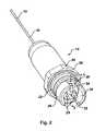
- FIG. 1is a cross-sectional view of a fiber optic connector
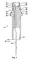
- FIG. 2is a perspective view of a male connector end of the fiber optic connector of FIG. 1 ;
- FIG. 3is a cross-sectional view of the male connector end of FIG. 2 taken along line 3 — 3 ;
- FIG. 4is a rear view of the male connector end of FIG. 2 ;
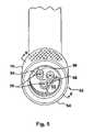
- FIG. 5is a perspective view of a female connector end of the fiber optic connector of FIG. 1 ;
- FIG. 6is a cross-sectional view of the female connector end of FIG. 5 taken along line 6 — 6 ;
- FIG. 7is a rear view of the female connector end of FIG. 5 ;
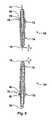
- FIG. 8is a cross-sectional, exploded view of a first termini and a second termini for use in the fiber optic cable connector of FIG. 1 .
- FIGS. 9A–Billustrate an exemplary prepared fiber end assembly and an exemplary terminated fiber assembly (TFA), respectively, for use in the fiber optic cable connector of FIG. 1 .
- a fiber optic connector 10has a male connector end 12 and a female connector end 14 for joining a first fiber optic cable end 16 and a second fiber optic cable end 18 of a fiber optic cable 19 .
- the fiber optic connector 10also includes a make-up nut 20 .
- the fiber optic cable 19is shielded by a capillary encapsulation tube 21 .
- the male connector end 12includes a male housing 22 for housing a plurality of male termini 24 protruding outward from a surface 26 .
- a first flange 28 and a second flange 30also protrude outwardly from the surface 26 protecting the plurality of termini 24 and forming a first key opening 32 and a second key opening 34 .
- the male housing 22includes a lip 36 having a lip outside diameter 38 for accommodating a metal seal 39 .
- the male housing 22also has a male housing outside diameter 40 and includes a groove 42 for receiving an elastomeric O-ring 44 , as best seen in FIG. 3 .
- the flanges 28 , 30have an outside flange diameter 46 .
- each termini 24is inserted into a keyed termini receiver hole 48 formed within the first connector end 12 .
- the keyed termini receiver hole 48includes a keyed slot 50 , as best seen in FIG. 4 .
- Each termini 24is used to terminate the fiber optic cable end 16 .
- the female connector end 14includes a female housing 52 having an outside surface 54 and a plurality of threads 56 .
- a plurality of female termini 58are disposed within the female housing 52 .
- the housing 52includes an inside diameter 60 sized to accept the outside diameter 40 of the male housing 22 .
- the female housing 52also includes a first key protrusion 62 and a second key protrusion 64 adapted to be received within the first key opening 32 and the second key opening 34 , respectively.
- the first key opening 32 and first key protrusion 62are sized differently from the second key opening 34 and the second key protrusion 64 to ensure proper alignment between the male and female connector ends 12 , 14 and, in combination, form a first alignment feature of the fiber optic connector 10 .
- the key protrusions 62 , 64are of sufficient length to prevent engagement of the termini until proper angular alignment between the ends 12 , 14 is achieved.
- the female housing 52also includes a plurality of keyed termini holes 66 for accepting the plurality of female termini 58 . Each termini hole 66 also includes a keyed slot 67 and has a sleeve 68 extending past the outward end of the termini 58 .
- each termini 24 , 58has a central axis 70 and includes a base part 72 and a top part 74 with the top part 74 terminating with a tip surface 76 .
- Each base part 72 of each termini 24 , 58includes a termini key 78 .
- the termini key 78is a pin 80 inserted in an opening 82 formed within the base part 72 and protruding outwardly therefrom.
- the tip surface 76 of each termini 24 , 58is angled and forms an angle ⁇ with a line perpendicular to the axis 70 of the termini 24 , 58 . In the preferred embodiment of the present invention, the angle ⁇ is approximately eight degrees (8°).
- the angled tip surface 76 at each termini 24is formed to mate with the corresponding termini 58 when both termini 24 , 58 are properly keyed into respective connector ends 12 , 14 .
- the angle ⁇can be increased to approximately fifteen degrees (15°).
- each termini 24 , 58is inserted into the termini keyed hole 48 , 66 , respectively.
- Each termini key 78fits into the corresponding keyed slot 50 , 67 of the termini keyed hole 48 , 66 .
- the keyed termini slot 50 , 67 and the termini key 78 of each termini 24 , 58define a second alignment feature of the fiber optic connector 10 which ensures that the male termini 24 is properly aligned with the female termini 58 for each particular termini connection.
- the make-up nut 20is adapted to fit over the male connector end 12 and includes threads 84 on the inside thereof to mate with the threads 56 of the female connector end 14 .
- the nut 20is fabricated from beryllium copper (BeCu) and, when torqued to specifications, provides sufficient elasticity to prevent back-off.
- BeCuberyllium copper
- the male and female housings 22 , 52also include a back-shell weld feature 86 that incorporates a welding surface 88 and a capillary opening 90 adapted to receive ends of the capillary encapsulation tube 21 .
- the female housing 52can include threads 91 for receiving threaded tube or other equipment that cannot be welded, as best seen in FIG. 6 .
- the connector ends 12 , 14are welded to the encapsulation tube 21 shielding the fiber optic cable 19 .
- the ends of the capillary tube 21are placed into the capillary opening 90 and welded at the welding surface 88 to attach the connector ends 12 , 14 to the capillary tube 21 .
- the first alignment feature 32 , 34 , 62 , 64ensures that the two connector ends 12 , 14 are properly aligned with respect to each other.
- the connector ends 12 , 14are rotated with respect to each other until the first key protrusion 62 and the second key protrusion 64 fit into the first key opening 32 and the second key opening 34 , respectively.
- the plurality of male termini 24fit into the plurality of sleeves 68 and slide to make connection with the female termini 58 , as best seen in FIG. 1 .
- the second alignment feature 50 , 67 , 78ensures that each termini connection is properly made.
- the angled tip surface 76 of each female termini 58registers with the angled tip surface 76 of the male termini 24 , as both termini keys of termini 24 , 58 are keyed into their respective slots 50 , 67 .
- the angled tip surface 76 of the termini 24 , 58ensures that retro-reflection is minimized.
- the make-up nut 20is secured onto the female portion 14 of the connector 10 by having the threads 56 , 84 mate.
- the metal seal 39sandwiched between the male and female connector ends 12 , 14 , provides a primary level of seal protection.
- the O-ring seal 44provides a secondary or back-up seal, should the metal seal 39 fail.
- the termini 24 , 58are a single channel termini, MIL-T-29504 equivalent, purchased from Packard-Hughes Interconnect Company that have a diameter of approximately two millimeters (2 mm) and have been further modified to include an approximately eight degree (8°) angle on the tip surface 76 thereof and to include the key 78 on the base part 72 thereof.
- the termini 24 and 58may be prepared as part of a terminated fiber assembly (TFA), which may be pre-assembled and subsequently inserted into the ends 12 and 14 , respectively, of the connector 10 .
- TFAterminated fiber assembly
- Such a TFAmay be assembled starting with a prepared fiber end assembly 900 , such as that shown in FIG. 9A , having a length of bare fiber 904 exposed via removal of protective (e.g., teflon) coating 906 .
- a protective tubing 904e.g., polyamide
- the fiber end assembly 900may be inserted into a back shell 913 of a terminus 924 , for example, until the protective tubing 904 contacts an inner wall 911 of the back shell 913 and a portion of the bare fiber 902 extends from an end of the terminus 924 . Accordingly, the length of the bare fiber 902 and tubing 904 may depend on the dimensions of the terminus 924 .
- epoxy 907(or other suitable adhesive) may be deposited into the back shell 913 , for example, via a syringe or other type epoxy dispenser, to hold the bare fiber 902 in the terminus 924 .
- a bead of epoxy 911may be deposited at the rear of the back shell 913 to act as a strain relief.
- the epoxymay then be cured, for example, by heating the terminus assembly in some type of heating chamber, taking care to protect the bare fiber 902 from direct contact with a heating surface.
- the bare fiber 902may be cleaved (e.g., just above a bead of epoxy 909 formed at an end of the terminus 924 ) using any suitable cleaving means, such as a hand-held cleave tool.
- the cleaved bare fiber 902 and terminus end 926may be air polished (e.g., using a 12 u Al-Oxide Foam backed paper in small circular motion) until the epoxy bead 909 feels smooth to the touch.
- the terminus end 926may then be further polished by inserting the terminus assembly into a polishing puck and polishing the terminus end 926 on a polishing film deposited on a glass plate, for example, using a number of patterned motions (e.g., FIG. 8 turns) designed to ensure even polishing.
- a light film of watermay be initially sprayed onto the polishing film.
- the terminus assemblymay then be removed from the puck and inserted into an apparatus (e.g., another type of polishing puck) for forming an angled tip surface (e.g., similar to the angled tip surfaces 76 shown in FIG. 8 ).
- the terminus assemblymay be clamped into the assembly and polished with a polishing machine using a suitable durometer pad (e.g., according to the material of the terminus 924 ) to ensure precise control of the polishing.
- the end 926 of the assemblymay then be polished (or machined) with suitable pressure and duration to form the angled tip surface having the desired angle (e.g., 8° as previously described).
- the light carrying properties of the terminus assemblymay be tested using any suitable tests, such as white light interferometer inspection.
- the terminus assemblymay be placed into a test fixture with white light transmitted therethrough, while comparing measured parameters to a set of expected parameters. Results of the test may be saved to file or printed and saved as quality documentation for the terminus assembly (or a batch of such assemblies).
- Insertion and return loss measurementsmay also be taken, for example, using pin and socket termini-pairs inserted into a test fixture.
- the termini pairsmay be inserted into the test fixture and aligned, with a proper radial force applied to bring the termini tips into physical contact.
- Insertion loss and/or return lossmay then be measured using any suitable techniques, such as transmitting light of a known power from one end of the termini junction and detecting the power of the light received at the other end and/or detecting the power of light reflected back through the termini junction (e.g., reflected from Bragg gratings).
- termini pairsmay be inserted into a connector or test housing and mated while subjecting the mated termini to a known temperature (e.g., 175°) for a predefined period of time (e.g., 6 hours minimum). The termini may then be re-inspected by taking any of the previously described measurements (e.g., white light interferometer, insertion and/or return loss).
- a known temperaturee.g. 175°
- a predefined period of timee.g., 6 hours minimum.
- the terminimay then be re-inspected by taking any of the previously described measurements (e.g., white light interferometer, insertion and/or return loss).
- a terminus structuremay be collapsed onto the fiber end assembly 900 , thus eliminating or reducing the need for epoxy.
- One technique for collapsing a terminus structure onto a prepared fiber end assemblyis described in the commonly assigned application Ser. No. 10/755,722 entitled “Low-Loss Large-Diameter Pigtail” filed Jan. 12, 2004, herein incorporated by reference in its entirety.
- terminated fiber assembliesmay be pre-assembled, tested, and later used to produce a final connector 10 .
- TFAsterminated fiber assemblies
- a variety of different type TFAsmay be produced and stocked, thus allowing for a modular connector design, in which the specific TFAs may be chosen, for example, according to a particular application. Utilizing pre-assembled TFAs may also facilitate field repair and replacement.
- the fiber optic connector 10has two alignment features that allow multiple termini connections be made while ensuring proper alignment of each of these termini connections.
- Another major advantage of the present inventionis that this multi-channel connector can be used in downhole applications.
- the connector 10 of the present inventioncan operate for temperatures ranging approximately from 0° C. to 175° C. (zero to one hundred seventy-five degrees Celsius) and ambient pressures of approximately one thousand (1,000) atmospheres.
- a further advantage of the present inventionis that the back-shell weld feature 86 not only facilitates attachment of the connector ends 12 , 14 onto the capillary tube, but also acts as both the strength element anchor for the fiber optic cable as well as the environment seal to prevent flooding of the cable.
- a number of features of the present inventioncontribute and ensure that this connector can be used in extremely harsh environment.
- One such featureis the choice of high strength, corrosion resistant alloys such as Inconel 718 and beryllium copper (BeCu).
- Another such featureis the thickness and material from which the nut 20 is manufactured. The elasticity of the make-up nut eliminates the need for safety wire or anti-rotation pawls.
Landscapes
- Physics & Mathematics (AREA)
- General Physics & Mathematics (AREA)
- Optics & Photonics (AREA)
- Mechanical Coupling Of Light Guides (AREA)
Abstract
Description
Claims (12)
Priority Applications (1)
| Application Number | Priority Date | Filing Date | Title |
|---|---|---|---|
| US10/772,091US7052185B2 (en) | 2000-06-15 | 2004-02-03 | Fiber optic cable connector with a plurality of alignment features |
Applications Claiming Priority (2)
| Application Number | Priority Date | Filing Date | Title |
|---|---|---|---|
| US09/594,645US6685361B1 (en) | 2000-06-15 | 2000-06-15 | Fiber optic cable connectors for downhole applications |
| US10/772,091US7052185B2 (en) | 2000-06-15 | 2004-02-03 | Fiber optic cable connector with a plurality of alignment features |
Related Parent Applications (1)
| Application Number | Title | Priority Date | Filing Date |
|---|---|---|---|
| US09/594,645Continuation-In-PartUS6685361B1 (en) | 2000-06-15 | 2000-06-15 | Fiber optic cable connectors for downhole applications |
Publications (2)
| Publication Number | Publication Date |
|---|---|
| US20040247251A1 US20040247251A1 (en) | 2004-12-09 |
| US7052185B2true US7052185B2 (en) | 2006-05-30 |
Family
ID=24379775
Family Applications (2)
| Application Number | Title | Priority Date | Filing Date |
|---|---|---|---|
| US09/594,645Expired - LifetimeUS6685361B1 (en) | 2000-06-15 | 2000-06-15 | Fiber optic cable connectors for downhole applications |
| US10/772,091Expired - LifetimeUS7052185B2 (en) | 2000-06-15 | 2004-02-03 | Fiber optic cable connector with a plurality of alignment features |
Family Applications Before (1)
| Application Number | Title | Priority Date | Filing Date |
|---|---|---|---|
| US09/594,645Expired - LifetimeUS6685361B1 (en) | 2000-06-15 | 2000-06-15 | Fiber optic cable connectors for downhole applications |
Country Status (5)
| Country | Link |
|---|---|
| US (2) | US6685361B1 (en) |
| EP (1) | EP1290480B1 (en) |
| CA (1) | CA2412625C (en) |
| DE (1) | DE60139315D1 (en) |
| WO (1) | WO2002025340A1 (en) |
Cited By (19)
| Publication number | Priority date | Publication date | Assignee | Title |
|---|---|---|---|---|
| US20070058907A1 (en)* | 2005-09-12 | 2007-03-15 | Mynott Geoffrey N | Opto-electric connector |
| US20070289779A1 (en)* | 2006-03-30 | 2007-12-20 | Schlumberger Technology Corporation | Providing a sensor array |
| US20080008420A1 (en)* | 2006-07-10 | 2008-01-10 | Schlumberger Technology Corporation | Apparatus and method for forming an optical fiber device |
| US8794337B2 (en) | 2009-02-18 | 2014-08-05 | Halliburton Energy Services, Inc. | Apparatus and method for controlling the connection and disconnection speed of downhole connectors |
| US11215768B2 (en) | 2017-06-28 | 2022-01-04 | Corning Research & Development Corporation | Fiber optic connectors and connectorization employing adhesive admitting adapters |
| US11300746B2 (en) | 2017-06-28 | 2022-04-12 | Corning Research & Development Corporation | Fiber optic port module inserts, assemblies and methods of making the same |
| US11604320B2 (en) | 2020-09-30 | 2023-03-14 | Corning Research & Development Corporation | Connector assemblies for telecommunication enclosures |
| US11650388B2 (en) | 2019-11-14 | 2023-05-16 | Corning Research & Development Corporation | Fiber optic networks having a self-supporting optical terminal and methods of installing the optical terminal |
| US11668890B2 (en) | 2017-06-28 | 2023-06-06 | Corning Research & Development Corporation | Multiports and other devices having optical connection ports with securing features and methods of making the same |
| US11686913B2 (en) | 2020-11-30 | 2023-06-27 | Corning Research & Development Corporation | Fiber optic cable assemblies and connector assemblies having a crimp ring and crimp body and methods of fabricating the same |
| US11703646B2 (en) | 2017-06-28 | 2023-07-18 | Corning Research & Development Corporation | Multiports and optical connectors with rotationally discrete locking and keying features |
| US11880076B2 (en) | 2020-11-30 | 2024-01-23 | Corning Research & Development Corporation | Fiber optic adapter assemblies including a conversion housing and a release housing |
| US11886010B2 (en) | 2019-10-07 | 2024-01-30 | Corning Research & Development Corporation | Fiber optic terminals and fiber optic networks having variable ratio couplers |
| US11927810B2 (en) | 2020-11-30 | 2024-03-12 | Corning Research & Development Corporation | Fiber optic adapter assemblies including a conversion housing and a release member |
| US11947167B2 (en) | 2021-05-26 | 2024-04-02 | Corning Research & Development Corporation | Fiber optic terminals and tools and methods for adjusting a split ratio of a fiber optic terminal |
| US11994722B2 (en) | 2020-11-30 | 2024-05-28 | Corning Research & Development Corporation | Fiber optic adapter assemblies including an adapter housing and a locking housing |
| US12019279B2 (en) | 2019-05-31 | 2024-06-25 | Corning Research & Development Corporation | Multiports and other devices having optical connection ports with sliding actuators and methods of making the same |
| US12271040B2 (en) | 2017-06-28 | 2025-04-08 | Corning Research & Development Corporation | Fiber optic extender ports, assemblies and methods of making the same |
| US12372727B2 (en) | 2020-10-30 | 2025-07-29 | Corning Research & Development Corporation | Female fiber optic connectors having a rocker latch arm and methods of making the same |
Families Citing this family (32)
| Publication number | Priority date | Publication date | Assignee | Title |
|---|---|---|---|---|
| US9239441B2 (en)* | 2000-05-26 | 2016-01-19 | Corning Cable Systems Llc | Fiber optic drop cables and preconnectorized assemblies having toning portions |
| US6962445B2 (en) | 2003-09-08 | 2005-11-08 | Adc Telecommunications, Inc. | Ruggedized fiber optic connection |
| US7210856B2 (en)* | 2004-03-02 | 2007-05-01 | Welldynamics, Inc. | Distributed temperature sensing in deep water subsea tree completions |
| US7641395B2 (en) | 2004-06-22 | 2010-01-05 | Halliburton Energy Serives, Inc. | Fiber optic splice housing and integral dry mate connector system |
| US7400803B2 (en)* | 2005-03-25 | 2008-07-15 | Welldynamics, B.V. | Method and apparatus for providing a hydrogen diffusion barrier for fiber optic cables used in hostile environments |
| US7218820B2 (en)* | 2004-07-22 | 2007-05-15 | Welldynamics, Inc. | Method and system for providing a hydrogen diffusion barrier for fiber optic cables used in hostile environments |
| US6907170B1 (en) | 2004-07-22 | 2005-06-14 | Halliburton Energy Services, Inc. | Hydrogen diffusion delay barrier for fiber optic cables used in hostile environments |
| US20060045428A1 (en)* | 2004-08-24 | 2006-03-02 | Thomas Theuerkorn | Fiber optic receptacle and plug assemblies |
| US7244066B2 (en)* | 2005-02-25 | 2007-07-17 | Corning Cable Systems Llc | Fiber optic receptacle and plug assembly including alignment sleeve insert |
| US7264402B2 (en)* | 2005-03-10 | 2007-09-04 | Corning Cable Systems Llc | Multi-fiber optic receptacle and plug assembly |
| US8021189B2 (en)* | 2006-02-27 | 2011-09-20 | Light Sources Inc. | Ultraviolet lamp for use in water purifiers |
| US7795813B2 (en)* | 2006-02-27 | 2010-09-14 | Light Sources, Inc. | Ultraviolet lamp for use in water purifiers |
| US7604505B2 (en)* | 2006-02-27 | 2009-10-20 | Light Sources, Inc. | Ultraviolet lamp for use in water purifiers |
| US7572065B2 (en) | 2007-01-24 | 2009-08-11 | Adc Telecommunications, Inc. | Hardened fiber optic connector |
| US7591595B2 (en) | 2007-01-24 | 2009-09-22 | Adc Telelcommunications, Inc. | Hardened fiber optic adapter |
| US7614797B2 (en)* | 2007-01-24 | 2009-11-10 | Adc Telecommunications, Inc. | Fiber optic connector mechanical interface converter |
| TWM317106U (en)* | 2007-02-16 | 2007-08-11 | Alltop Technology Co Ltd | Power connector |
| US7677814B2 (en)* | 2007-05-06 | 2010-03-16 | Adc Telecommunications, Inc. | Mechanical interface converter for making non-ruggedized fiber optic connectors compatible with a ruggedized fiber optic adapter |
| US7722258B2 (en)* | 2007-05-06 | 2010-05-25 | Adc Telecommunications, Inc. | Interface converter for SC fiber optic connectors |
| US7686519B2 (en)* | 2007-06-18 | 2010-03-30 | Adc Telecommunications, Inc. | Hardened fiber optic housing and cable assembly |
| US7762726B2 (en)* | 2007-12-11 | 2010-07-27 | Adc Telecommunications, Inc. | Hardened fiber optic connection system |
| US8403570B2 (en)* | 2008-04-10 | 2013-03-26 | Amphenol Corporation | Plural fiber optic interconnect |
| US8123547B2 (en)* | 2009-12-17 | 2012-02-28 | Knowles Electronics, Llc | Connector assembly |
| US8540435B2 (en) | 2011-07-22 | 2013-09-24 | Corning Cable Systems Llc | Ferrule retainers having access window(s) for accessing and/or referencing a fiber optic ferrule, and related fiber optic connector assemblies, connectors, and referencing methods |
| BR112015019096A2 (en)* | 2013-03-01 | 2017-07-18 | Halliburton Energy Services Inc | profiling cable connector including an electromagnet and a metal |
| US9611734B2 (en) | 2013-05-21 | 2017-04-04 | Hallitburton Energy Services, Inc. | Connecting fiber optic cables |
| WO2014206976A1 (en) | 2013-06-27 | 2014-12-31 | Tyco Electronics Raychem Bvba | Fiber optic cable anchoring device for use with fiber optic connectors and methods of using the same |
| MX2017011384A (en)* | 2015-03-06 | 2018-01-15 | Fujikura Ltd | OPTICAL CONNECTOR OF THE SIDE OF THE PLUG AND OPTICAL CONNECTOR SYSTEM. |
| US11187859B2 (en) | 2017-06-28 | 2021-11-30 | Corning Research & Development Corporation | Fiber optic connectors and methods of making the same |
| US10908364B2 (en) | 2019-02-08 | 2021-02-02 | Corning Research & Development Corporation | Fiber optic connectors with at least one field-installable termini |
| US11294133B2 (en) | 2019-07-31 | 2022-04-05 | Corning Research & Development Corporation | Fiber optic networks using multiports and cable assemblies with cable-to-connector orientation |
| US11536921B2 (en) | 2020-02-11 | 2022-12-27 | Corning Research & Development Corporation | Fiber optic terminals having one or more loopback assemblies |
Citations (20)
| Publication number | Priority date | Publication date | Assignee | Title |
|---|---|---|---|---|
| US3945700A (en) | 1974-08-06 | 1976-03-23 | Boston Insulated Wire & Cable Co. | Connector with fluid-resistant sleeve assembly |
| US4140367A (en) | 1976-10-08 | 1979-02-20 | Bunker Ramo Corporation | Multiple channel connector for fiber optic cables |
| US4225214A (en) | 1978-09-18 | 1980-09-30 | Trw Inc. | Connector construction |
| US4252406A (en) | 1978-09-05 | 1981-02-24 | The United States Of America As Represented By The Secretary Of The Army | Connector for optical fibers |
| US4759601A (en) | 1985-06-24 | 1988-07-26 | Schlumberger Technology Corporation | Fiber optic connector assembly |
| US4801191A (en) | 1985-09-25 | 1989-01-31 | The Furukawa Electric Co., Ltd. | Connecting section for optical fiber cable |
| US4802861A (en) | 1987-06-15 | 1989-02-07 | Boeing Vertol Company | Self-aligning electrical connector |
| US4829407A (en) | 1987-11-06 | 1989-05-09 | Oxley Developments Company Limited | Indicator lamps |
| US5018822A (en) | 1989-12-11 | 1991-05-28 | Litton Systems, Inc. | Environmentally sealed multichannel fiber optic connector |
| US5064268A (en) | 1990-12-07 | 1991-11-12 | The United States Of America As Represented By The Secretary Of The Navy | High pressure fiber optic connector plug |
| US5067783A (en)* | 1990-10-16 | 1991-11-26 | At&T Bell Laboratories | Optical fiber connector buildout system |
| US5293581A (en) | 1993-04-16 | 1994-03-08 | Alcoa Fujikura Ltd. | Flexible connector assembly for fiber optics |
| US5301213A (en) | 1993-06-08 | 1994-04-05 | Combustion Engineering, Inc. | Method of field replacement of an electrical connector for nuclear reactor instrumentation |
| US5384885A (en) | 1993-10-28 | 1995-01-24 | At&T Corp. | Variable attenuation optical fiber coupling |
| US5433275A (en) | 1994-07-19 | 1995-07-18 | Baker Hughes Incorporated | Double-threaded anchor tubing assembly |
| US5590229A (en) | 1994-04-22 | 1996-12-31 | Litton Systems, Inc. | Multichannel fiber optic connector |
| US5925879A (en) | 1997-05-09 | 1999-07-20 | Cidra Corporation | Oil and gas well packer having fiber optic Bragg Grating sensors for downhole insitu inflation monitoring |
| US5928034A (en) | 1996-07-30 | 1999-07-27 | Sumitomo Wiring Systems, Ltd. | Connector with terminal locking and locking assurance features |
| US5997362A (en) | 1997-03-25 | 1999-12-07 | Yazaki Corporation | Connector |
| US6234683B1 (en) | 1999-09-13 | 2001-05-22 | Stratos Lightwave, Inc. | Field repairable hermaphroditic connector |
- 2000
- 2000-06-15USUS09/594,645patent/US6685361B1/ennot_activeExpired - Lifetime
- 2001
- 2001-05-16WOPCT/US2001/015792patent/WO2002025340A1/enactiveSearch and Examination
- 2001-05-16EPEP01944146Apatent/EP1290480B1/ennot_activeExpired - Lifetime
- 2001-05-16CACA002412625Apatent/CA2412625C/ennot_activeExpired - Fee Related
- 2001-05-16DEDE60139315Tpatent/DE60139315D1/ennot_activeExpired - Lifetime
- 2004
- 2004-02-03USUS10/772,091patent/US7052185B2/ennot_activeExpired - Lifetime
Patent Citations (20)
| Publication number | Priority date | Publication date | Assignee | Title |
|---|---|---|---|---|
| US3945700A (en) | 1974-08-06 | 1976-03-23 | Boston Insulated Wire & Cable Co. | Connector with fluid-resistant sleeve assembly |
| US4140367A (en) | 1976-10-08 | 1979-02-20 | Bunker Ramo Corporation | Multiple channel connector for fiber optic cables |
| US4252406A (en) | 1978-09-05 | 1981-02-24 | The United States Of America As Represented By The Secretary Of The Army | Connector for optical fibers |
| US4225214A (en) | 1978-09-18 | 1980-09-30 | Trw Inc. | Connector construction |
| US4759601A (en) | 1985-06-24 | 1988-07-26 | Schlumberger Technology Corporation | Fiber optic connector assembly |
| US4801191A (en) | 1985-09-25 | 1989-01-31 | The Furukawa Electric Co., Ltd. | Connecting section for optical fiber cable |
| US4802861A (en) | 1987-06-15 | 1989-02-07 | Boeing Vertol Company | Self-aligning electrical connector |
| US4829407A (en) | 1987-11-06 | 1989-05-09 | Oxley Developments Company Limited | Indicator lamps |
| US5018822A (en) | 1989-12-11 | 1991-05-28 | Litton Systems, Inc. | Environmentally sealed multichannel fiber optic connector |
| US5067783A (en)* | 1990-10-16 | 1991-11-26 | At&T Bell Laboratories | Optical fiber connector buildout system |
| US5064268A (en) | 1990-12-07 | 1991-11-12 | The United States Of America As Represented By The Secretary Of The Navy | High pressure fiber optic connector plug |
| US5293581A (en) | 1993-04-16 | 1994-03-08 | Alcoa Fujikura Ltd. | Flexible connector assembly for fiber optics |
| US5301213A (en) | 1993-06-08 | 1994-04-05 | Combustion Engineering, Inc. | Method of field replacement of an electrical connector for nuclear reactor instrumentation |
| US5384885A (en) | 1993-10-28 | 1995-01-24 | At&T Corp. | Variable attenuation optical fiber coupling |
| US5590229A (en) | 1994-04-22 | 1996-12-31 | Litton Systems, Inc. | Multichannel fiber optic connector |
| US5433275A (en) | 1994-07-19 | 1995-07-18 | Baker Hughes Incorporated | Double-threaded anchor tubing assembly |
| US5928034A (en) | 1996-07-30 | 1999-07-27 | Sumitomo Wiring Systems, Ltd. | Connector with terminal locking and locking assurance features |
| US5997362A (en) | 1997-03-25 | 1999-12-07 | Yazaki Corporation | Connector |
| US5925879A (en) | 1997-05-09 | 1999-07-20 | Cidra Corporation | Oil and gas well packer having fiber optic Bragg Grating sensors for downhole insitu inflation monitoring |
| US6234683B1 (en) | 1999-09-13 | 2001-05-22 | Stratos Lightwave, Inc. | Field repairable hermaphroditic connector |
Non-Patent Citations (2)
| Title |
|---|
| International Search Report for PCT/US01/15792, dated Mar. 14, 2002. |
| Packard-Hughes Interconnect Fiber Optic Connectors, Fiber Optic Termini, MIL-T-29504, pp. 1-9. |
Cited By (51)
| Publication number | Priority date | Publication date | Assignee | Title |
|---|---|---|---|---|
| US20070058907A1 (en)* | 2005-09-12 | 2007-03-15 | Mynott Geoffrey N | Opto-electric connector |
| US7572063B2 (en)* | 2005-09-12 | 2009-08-11 | Stratos International, Inc. | Opto-electric connector |
| US20070289779A1 (en)* | 2006-03-30 | 2007-12-20 | Schlumberger Technology Corporation | Providing a sensor array |
| US7836959B2 (en) | 2006-03-30 | 2010-11-23 | Schlumberger Technology Corporation | Providing a sensor array |
| US20080008420A1 (en)* | 2006-07-10 | 2008-01-10 | Schlumberger Technology Corporation | Apparatus and method for forming an optical fiber device |
| US7634168B2 (en) | 2006-07-10 | 2009-12-15 | Schlumberger Technology Corporation | Apparatus and method for forming an optical fiber device |
| US20100038036A1 (en)* | 2006-07-10 | 2010-02-18 | Schlumberger Technology Corporation | Apparatus and method for forming an optical fiber device |
| US8794337B2 (en) | 2009-02-18 | 2014-08-05 | Halliburton Energy Services, Inc. | Apparatus and method for controlling the connection and disconnection speed of downhole connectors |
| US11789214B2 (en) | 2017-06-28 | 2023-10-17 | Corning Research & Development Corporation | Multiports and other devices having keyed connection ports and securing features and methods of making the same |
| US12092878B2 (en) | 2017-06-28 | 2024-09-17 | Corning Research & Development Corporation | Fiber optic connectors having a keying structure and methods of making the same |
| US11300746B2 (en) | 2017-06-28 | 2022-04-12 | Corning Research & Development Corporation | Fiber optic port module inserts, assemblies and methods of making the same |
| US11409055B2 (en) | 2017-06-28 | 2022-08-09 | Corning Optical Communications LLC | Multiports having connection ports with associated securing features and methods of making the same |
| US11415759B2 (en) | 2017-06-28 | 2022-08-16 | Corning Optical Communications LLC | Multiports having a connection port insert and methods of making the same |
| US11460646B2 (en) | 2017-06-28 | 2022-10-04 | Corning Research & Development Corporation | Fiber optic connectors and multiport assemblies including retention features |
| US11487065B2 (en) | 2017-06-28 | 2022-11-01 | Corning Research & Development Corporation | Multiports and devices having a connector port with a rotating securing feature |
| US11536913B2 (en) | 2017-06-28 | 2022-12-27 | Corning Research & Development Corporation | Fiber optic connectors and connectorization employing adhesive admitting adapters |
| US11579377B2 (en) | 2017-06-28 | 2023-02-14 | Corning Research & Development Corporation | Compact fiber optic connectors, cable assemblies and methods of making the same with alignment elements |
| US12429655B2 (en) | 2017-06-28 | 2025-09-30 | Corning Optical Communications LLC | Multiports having connection ports with associated securing features and methods of making the same |
| US11624877B2 (en) | 2017-06-28 | 2023-04-11 | Corning Research & Development Corporation | Multiports having connection ports with securing features that actuate flexures and methods of making the same |
| US12379551B2 (en) | 2017-06-28 | 2025-08-05 | Corning Optical Communications LLC | Multiports having connection ports formed in the shell and associated securing features |
| US11656414B2 (en) | 2017-06-28 | 2023-05-23 | Corning Research & Development Corporation | Multiports and other devices having connection ports with securing features and methods of making the same |
| US11668890B2 (en) | 2017-06-28 | 2023-06-06 | Corning Research & Development Corporation | Multiports and other devices having optical connection ports with securing features and methods of making the same |
| US12379552B2 (en) | 2017-06-28 | 2025-08-05 | Corning Research & Development Corporation | Compact fiber optic connectors, cable assemblies and methods of making the same |
| US11703646B2 (en) | 2017-06-28 | 2023-07-18 | Corning Research & Development Corporation | Multiports and optical connectors with rotationally discrete locking and keying features |
| US11215768B2 (en) | 2017-06-28 | 2022-01-04 | Corning Research & Development Corporation | Fiber optic connectors and connectorization employing adhesive admitting adapters |
| US12353025B2 (en) | 2017-06-28 | 2025-07-08 | Corning Optical Communications LLC | Multiports having a connection port insert and methods of making the same |
| US11886017B2 (en) | 2017-06-28 | 2024-01-30 | Corning Research & Development Corporation | Multiports and other devices having connection ports with securing features and methods of making the same |
| US12353024B2 (en) | 2017-06-28 | 2025-07-08 | Corning Research & Development Corporation | Multiports and optical connectors with rotationally discrete locking and keying features |
| US11906792B2 (en) | 2017-06-28 | 2024-02-20 | Corning Research & Development Corporation | Compact fiber optic connectors having multiple connector footprints, along with cable assemblies and methods of making the same |
| US11914197B2 (en) | 2017-06-28 | 2024-02-27 | Corning Research & Development Corporation | Compact fiber optic connectors having multiple connector footprints, along with cable assemblies and methods of making the same |
| US11914198B2 (en) | 2017-06-28 | 2024-02-27 | Corning Research & Development Corporation | Compact fiber optic connectors having multiple connector footprints, along with cable assemblies and methods of making the same |
| US12298568B2 (en) | 2017-06-28 | 2025-05-13 | Corning Research & Development Corporation | Fiber optic connectors and multiport assemblies including retention features |
| US11940656B2 (en) | 2017-06-28 | 2024-03-26 | Corning Research & Development Corporation | Compact fiber optic connectors, cable assemblies and methods of making the same |
| US12276846B2 (en) | 2017-06-28 | 2025-04-15 | Corning Research & Development Corporation | Compact fiber optic connectors, cable assemblies and methods of making the same |
| US11966089B2 (en) | 2017-06-28 | 2024-04-23 | Corning Optical Communications, Llc | Multiports having connection ports formed in the shell and associated securing features |
| US12271040B2 (en) | 2017-06-28 | 2025-04-08 | Corning Research & Development Corporation | Fiber optic extender ports, assemblies and methods of making the same |
| US12013578B2 (en) | 2017-06-28 | 2024-06-18 | Corning Research & Development Corporation | Multifiber fiber optic connectors, cable assemblies and methods of making the same |
| US12174432B2 (en) | 2017-06-28 | 2024-12-24 | Corning Research & Development Corporation | Fiber optic connectors and connectorization employing adhesive admitting adapters |
| US11287581B2 (en)* | 2017-06-28 | 2022-03-29 | Corning Research & Development Corporation | Compact fiber optic connectors, cable assemblies and methods of making the same |
| US12019279B2 (en) | 2019-05-31 | 2024-06-25 | Corning Research & Development Corporation | Multiports and other devices having optical connection ports with sliding actuators and methods of making the same |
| US11886010B2 (en) | 2019-10-07 | 2024-01-30 | Corning Research & Development Corporation | Fiber optic terminals and fiber optic networks having variable ratio couplers |
| US11650388B2 (en) | 2019-11-14 | 2023-05-16 | Corning Research & Development Corporation | Fiber optic networks having a self-supporting optical terminal and methods of installing the optical terminal |
| US12019285B2 (en) | 2020-09-30 | 2024-06-25 | Corning Research & Development Corporation | Connector assemblies for telecommunication enclosures |
| US11604320B2 (en) | 2020-09-30 | 2023-03-14 | Corning Research & Development Corporation | Connector assemblies for telecommunication enclosures |
| US12372727B2 (en) | 2020-10-30 | 2025-07-29 | Corning Research & Development Corporation | Female fiber optic connectors having a rocker latch arm and methods of making the same |
| US11994722B2 (en) | 2020-11-30 | 2024-05-28 | Corning Research & Development Corporation | Fiber optic adapter assemblies including an adapter housing and a locking housing |
| US11927810B2 (en) | 2020-11-30 | 2024-03-12 | Corning Research & Development Corporation | Fiber optic adapter assemblies including a conversion housing and a release member |
| US12345927B2 (en) | 2020-11-30 | 2025-07-01 | Corning Research & Development Corporation | Fiber optic adapter assemblies including a conversion housing and a release housing |
| US11880076B2 (en) | 2020-11-30 | 2024-01-23 | Corning Research & Development Corporation | Fiber optic adapter assemblies including a conversion housing and a release housing |
| US11686913B2 (en) | 2020-11-30 | 2023-06-27 | Corning Research & Development Corporation | Fiber optic cable assemblies and connector assemblies having a crimp ring and crimp body and methods of fabricating the same |
| US11947167B2 (en) | 2021-05-26 | 2024-04-02 | Corning Research & Development Corporation | Fiber optic terminals and tools and methods for adjusting a split ratio of a fiber optic terminal |
Also Published As
| Publication number | Publication date |
|---|---|
| DE60139315D1 (en) | 2009-09-03 |
| CA2412625A1 (en) | 2002-03-28 |
| CA2412625C (en) | 2009-07-14 |
| EP1290480B1 (en) | 2009-07-22 |
| US20040247251A1 (en) | 2004-12-09 |
| WO2002025340A8 (en) | 2002-05-23 |
| US6685361B1 (en) | 2004-02-03 |
| WO2002025340A1 (en) | 2002-03-28 |
| EP1290480A1 (en) | 2003-03-12 |
Similar Documents
| Publication | Publication Date | Title |
|---|---|---|
| US7052185B2 (en) | Fiber optic cable connector with a plurality of alignment features | |
| US7128471B2 (en) | Single-use fiber optic cable | |
| CN104101955B (en) | Optical connector apparatus | |
| US7329049B2 (en) | Splice connector for verifying an acceptable splice termination | |
| US6422759B1 (en) | Fiber optic connector | |
| US6069992A (en) | Connector system with precision alignment | |
| JP4727674B2 (en) | Optical fiber termination assembly | |
| US20050031285A1 (en) | Multifiber connector, installation tool and associated methods of validating optical fiber continuity | |
| EP0205984A1 (en) | Terminated optical fiber and methods of making | |
| EP0628841A1 (en) | Fiber optic splicer-connector | |
| US20070164562A1 (en) | Method and apparatus for connecting small diameter tubing | |
| US4737009A (en) | Independent optical ferrule and optical fiber connector which uses the ferrule and replaceable optical plug using the ferrule | |
| US4296999A (en) | Optical fibre connectors | |
| US4205897A (en) | Fiber optic connector for single fiber | |
| CN100580492C (en) | Inner housing for optical waveguide plug-in connectors | |
| JP4932303B2 (en) | Optical communication module and manufacturing method thereof | |
| KR101460978B1 (en) | Optical and electrical hybrid connector | |
| US5774613A (en) | Ferrule for an optical fiber connector | |
| JP4192751B2 (en) | Optical fiber connector and optical fiber connection method | |
| CN101710197B (en) | Optical connector and assembly thereof | |
| McMurray | Tests and results of active alignment fiber optic connectors for space usage | |
| Kevern et al. | 2 Passive Alignment | |
| CN113835162A (en) | Splicing core and optical fiber quick connector thereof | |
| GB1572502A (en) | Optical waveguide couplings | |
| CN115542470A (en) | Underwater wet-plugging accurate butt-joint optical fiber contact pin |
Legal Events
| Date | Code | Title | Description |
|---|---|---|---|
| AS | Assignment | Owner name:WEATHERFORD/LAMB, INC., TEXAS Free format text:ASSIGNMENT OF ASSIGNORS INTEREST;ASSIGNORS:RUBINO, ROBERT A;MISHRIKY, NABIL E;CAISSE, DANIEL;AND OTHERS;REEL/FRAME:015011/0469;SIGNING DATES FROM 20040719 TO 20040729 | |
| STCF | Information on status: patent grant | Free format text:PATENTED CASE | |
| FEPP | Fee payment procedure | Free format text:PAYOR NUMBER ASSIGNED (ORIGINAL EVENT CODE: ASPN); ENTITY STATUS OF PATENT OWNER: LARGE ENTITY | |
| FPAY | Fee payment | Year of fee payment:4 | |
| FPAY | Fee payment | Year of fee payment:8 | |
| AS | Assignment | Owner name:WEATHERFORD TECHNOLOGY HOLDINGS, LLC, TEXAS Free format text:ASSIGNMENT OF ASSIGNORS INTEREST;ASSIGNOR:WEATHERFORD/LAMB, INC.;REEL/FRAME:034526/0272 Effective date:20140901 | |
| AS | Assignment | Owner name:WEBSTER BANK, NATIONAL ASSOCIATION, CONNECTICUT Free format text:PATENT COLLATERAL ASSIGNMENT AND SECURITY AGREEMENT;ASSIGNOR:CIDRA CORPORATE SERVICES, INC.;REEL/FRAME:036818/0469 Effective date:20150902 | |
| AS | Assignment | Owner name:CIDRA CORPORATE SERVICES, INC., CONNECTICUT Free format text:RELEASE AND REASSIGNMENT OF PATENTS;ASSIGNOR:WEBSTER BANK, NATIONAL ASSOCIATION;REEL/FRAME:044097/0723 Effective date:20170929 | |
| MAFP | Maintenance fee payment | Free format text:PAYMENT OF MAINTENANCE FEE, 12TH YEAR, LARGE ENTITY (ORIGINAL EVENT CODE: M1553) Year of fee payment:12 | |
| AS | Assignment | Owner name:WELLS FARGO BANK NATIONAL ASSOCIATION AS AGENT, TEXAS Free format text:SECURITY INTEREST;ASSIGNORS:WEATHERFORD TECHNOLOGY HOLDINGS LLC;WEATHERFORD NETHERLANDS B.V.;WEATHERFORD NORGE AS;AND OTHERS;REEL/FRAME:051891/0089 Effective date:20191213 | |
| AS | Assignment | Owner name:DEUTSCHE BANK TRUST COMPANY AMERICAS, AS ADMINISTR Free format text:SECURITY INTEREST;ASSIGNORS:WEATHERFORD TECHNOLOGY HOLDINGS, LLC;WEATHERFORD NETHERLANDS B.V.;WEATHERFORD NORGE AS;AND OTHERS;REEL/FRAME:051419/0140 Effective date:20191213 Owner name:DEUTSCHE BANK TRUST COMPANY AMERICAS, AS ADMINISTRATIVE AGENT, NEW YORK Free format text:SECURITY INTEREST;ASSIGNORS:WEATHERFORD TECHNOLOGY HOLDINGS, LLC;WEATHERFORD NETHERLANDS B.V.;WEATHERFORD NORGE AS;AND OTHERS;REEL/FRAME:051419/0140 Effective date:20191213 | |
| AS | Assignment | Owner name:PRECISION ENERGY SERVICES, INC., TEXAS Free format text:RELEASE BY SECURED PARTY;ASSIGNOR:WELLS FARGO BANK, NATIONAL ASSOCIATION;REEL/FRAME:053838/0323 Effective date:20200828 Owner name:WEATHERFORD U.K. LIMITED, TEXAS Free format text:RELEASE BY SECURED PARTY;ASSIGNOR:WELLS FARGO BANK, NATIONAL ASSOCIATION;REEL/FRAME:053838/0323 Effective date:20200828 Owner name:WEATHERFORD CANADA LTD., TEXAS Free format text:RELEASE BY SECURED PARTY;ASSIGNOR:WELLS FARGO BANK, NATIONAL ASSOCIATION;REEL/FRAME:053838/0323 Effective date:20200828 Owner name:WEATHERFORD SWITZERLAND TRADING AND DEVELOPMENT GMBH, TEXAS Free format text:RELEASE BY SECURED PARTY;ASSIGNOR:WELLS FARGO BANK, NATIONAL ASSOCIATION;REEL/FRAME:053838/0323 Effective date:20200828 Owner name:WEATHERFORD NORGE AS, TEXAS Free format text:RELEASE BY SECURED PARTY;ASSIGNOR:WELLS FARGO BANK, NATIONAL ASSOCIATION;REEL/FRAME:053838/0323 Effective date:20200828 Owner name:WEATHERFORD NETHERLANDS B.V., TEXAS Free format text:RELEASE BY SECURED PARTY;ASSIGNOR:WELLS FARGO BANK, NATIONAL ASSOCIATION;REEL/FRAME:053838/0323 Effective date:20200828 Owner name:PRECISION ENERGY SERVICES ULC, TEXAS Free format text:RELEASE BY SECURED PARTY;ASSIGNOR:WELLS FARGO BANK, NATIONAL ASSOCIATION;REEL/FRAME:053838/0323 Effective date:20200828 Owner name:WEATHERFORD TECHNOLOGY HOLDINGS, LLC, TEXAS Free format text:RELEASE BY SECURED PARTY;ASSIGNOR:WELLS FARGO BANK, NATIONAL ASSOCIATION;REEL/FRAME:053838/0323 Effective date:20200828 Owner name:HIGH PRESSURE INTEGRITY, INC., TEXAS Free format text:RELEASE BY SECURED PARTY;ASSIGNOR:WELLS FARGO BANK, NATIONAL ASSOCIATION;REEL/FRAME:053838/0323 Effective date:20200828 Owner name:WILMINGTON TRUST, NATIONAL ASSOCIATION, MINNESOTA Free format text:SECURITY INTEREST;ASSIGNORS:WEATHERFORD TECHNOLOGY HOLDINGS, LLC;WEATHERFORD NETHERLANDS B.V.;WEATHERFORD NORGE AS;AND OTHERS;REEL/FRAME:054288/0302 Effective date:20200828 | |
| AS | Assignment | Owner name:WILMINGTON TRUST, NATIONAL ASSOCIATION, MINNESOTA Free format text:SECURITY INTEREST;ASSIGNORS:WEATHERFORD TECHNOLOGY HOLDINGS, LLC;WEATHERFORD NETHERLANDS B.V.;WEATHERFORD NORGE AS;AND OTHERS;REEL/FRAME:057683/0706 Effective date:20210930 Owner name:WEATHERFORD U.K. LIMITED, TEXAS Free format text:RELEASE BY SECURED PARTY;ASSIGNOR:WILMINGTON TRUST, NATIONAL ASSOCIATION;REEL/FRAME:057683/0423 Effective date:20210930 Owner name:PRECISION ENERGY SERVICES ULC, TEXAS Free format text:RELEASE BY SECURED PARTY;ASSIGNOR:WILMINGTON TRUST, NATIONAL ASSOCIATION;REEL/FRAME:057683/0423 Effective date:20210930 Owner name:WEATHERFORD SWITZERLAND TRADING AND DEVELOPMENT GMBH, TEXAS Free format text:RELEASE BY SECURED PARTY;ASSIGNOR:WILMINGTON TRUST, NATIONAL ASSOCIATION;REEL/FRAME:057683/0423 Effective date:20210930 Owner name:WEATHERFORD CANADA LTD, TEXAS Free format text:RELEASE BY SECURED PARTY;ASSIGNOR:WILMINGTON TRUST, NATIONAL ASSOCIATION;REEL/FRAME:057683/0423 Effective date:20210930 Owner name:PRECISION ENERGY SERVICES, INC., TEXAS Free format text:RELEASE BY SECURED PARTY;ASSIGNOR:WILMINGTON TRUST, NATIONAL ASSOCIATION;REEL/FRAME:057683/0423 Effective date:20210930 Owner name:HIGH PRESSURE INTEGRITY, INC., TEXAS Free format text:RELEASE BY SECURED PARTY;ASSIGNOR:WILMINGTON TRUST, NATIONAL ASSOCIATION;REEL/FRAME:057683/0423 Effective date:20210930 Owner name:WEATHERFORD NORGE AS, TEXAS Free format text:RELEASE BY SECURED PARTY;ASSIGNOR:WILMINGTON TRUST, NATIONAL ASSOCIATION;REEL/FRAME:057683/0423 Effective date:20210930 Owner name:WEATHERFORD NETHERLANDS B.V., TEXAS Free format text:RELEASE BY SECURED PARTY;ASSIGNOR:WILMINGTON TRUST, NATIONAL ASSOCIATION;REEL/FRAME:057683/0423 Effective date:20210930 Owner name:WEATHERFORD TECHNOLOGY HOLDINGS, LLC, TEXAS Free format text:RELEASE BY SECURED PARTY;ASSIGNOR:WILMINGTON TRUST, NATIONAL ASSOCIATION;REEL/FRAME:057683/0423 Effective date:20210930 | |
| AS | Assignment | Owner name:WELLS FARGO BANK, NATIONAL ASSOCIATION, NORTH CAROLINA Free format text:PATENT SECURITY INTEREST ASSIGNMENT AGREEMENT;ASSIGNOR:DEUTSCHE BANK TRUST COMPANY AMERICAS;REEL/FRAME:063470/0629 Effective date:20230131 |