US7050783B2 - Accessory detection system - Google Patents
Accessory detection systemDownload PDFInfo
- Publication number
- US7050783B2 US7050783B2US10/080,467US8046702AUS7050783B2US 7050783 B2US7050783 B2US 7050783B2US 8046702 AUS8046702 AUS 8046702AUS 7050783 B2US7050783 B2US 7050783B2
- Authority
- US
- United States
- Prior art keywords
- accessory
- software code
- communication device
- memory
- patch
- Prior art date
- Legal status (The legal status is an assumption and is not a legal conclusion. Google has not performed a legal analysis and makes no representation as to the accuracy of the status listed.)
- Expired - Lifetime, expires
Links
- 238000001514detection methodMethods0.000titledescription25
- 238000004891communicationMethods0.000claimsabstractdescription82
- 238000000034methodMethods0.000claimsabstractdescription58
- 239000004020conductorSubstances0.000claimsdescription26
- 230000003993interactionEffects0.000claimsdescription20
- 230000001413cellular effectEffects0.000claimsdescription7
- 230000008569processEffects0.000abstractdescription11
- 230000008901benefitEffects0.000description18
- 238000010586diagramMethods0.000description16
- 238000004458analytical methodMethods0.000description7
- 230000009471actionEffects0.000description4
- 238000012545processingMethods0.000description4
- 238000012546transferMethods0.000description4
- 238000013500data storageMethods0.000description3
- 230000004048modificationEffects0.000description3
- 238000012986modificationMethods0.000description3
- 238000012544monitoring processMethods0.000description2
- 230000009467reductionEffects0.000description2
- 230000004913activationEffects0.000description1
- 230000003321amplificationEffects0.000description1
- 230000003466anti-cipated effectEffects0.000description1
- 230000006399behaviorEffects0.000description1
- 230000008859changeEffects0.000description1
- 230000003111delayed effectEffects0.000description1
- 238000012217deletionMethods0.000description1
- 230000037430deletionEffects0.000description1
- 239000000835fiberSubstances0.000description1
- 230000000977initiatory effectEffects0.000description1
- 230000009191jumpingEffects0.000description1
- 238000004519manufacturing processMethods0.000description1
- 238000013507mappingMethods0.000description1
- 238000003199nucleic acid amplification methodMethods0.000description1
- 230000003287optical effectEffects0.000description1
- 230000004044responseEffects0.000description1
- 238000012360testing methodMethods0.000description1
- 230000000007visual effectEffects0.000description1
Images


Classifications
- H—ELECTRICITY
- H04—ELECTRIC COMMUNICATION TECHNIQUE
- H04M—TELEPHONIC COMMUNICATION
- H04M1/00—Substation equipment, e.g. for use by subscribers
- H04M1/60—Substation equipment, e.g. for use by subscribers including speech amplifiers
- H04M1/6033—Substation equipment, e.g. for use by subscribers including speech amplifiers for providing handsfree use or a loudspeaker mode in telephone sets
- H04M1/6041—Portable telephones adapted for handsfree use
- H04M1/6075—Portable telephones adapted for handsfree use adapted for handsfree use in a vehicle
- H—ELECTRICITY
- H04—ELECTRIC COMMUNICATION TECHNIQUE
- H04B—TRANSMISSION
- H04B1/00—Details of transmission systems, not covered by a single one of groups H04B3/00 - H04B13/00; Details of transmission systems not characterised by the medium used for transmission
- H04B1/38—Transceivers, i.e. devices in which transmitter and receiver form a structural unit and in which at least one part is used for functions of transmitting and receiving
- H04B1/3827—Portable transceivers
- H04B1/3877—Arrangements for enabling portable transceivers to be used in a fixed position, e.g. cradles or boosters
- H—ELECTRICITY
- H04—ELECTRIC COMMUNICATION TECHNIQUE
- H04M—TELEPHONIC COMMUNICATION
- H04M1/00—Substation equipment, e.g. for use by subscribers
- H04M1/72—Mobile telephones; Cordless telephones, i.e. devices for establishing wireless links to base stations without route selection
- H04M1/724—User interfaces specially adapted for cordless or mobile telephones
- H04M1/72403—User interfaces specially adapted for cordless or mobile telephones with means for local support of applications that increase the functionality
- H04M1/72409—User interfaces specially adapted for cordless or mobile telephones with means for local support of applications that increase the functionality by interfacing with external accessories
- H04M1/724098—Interfacing with an on-board device of a vehicle
Definitions
- the present inventionrelates to communication device accessories and in particular to communication device accessory interface and detection.
- Portable electronic devicesare popular devices used by individuals to track and store data, manage information, and communicate with other electronic devices.
- portable electronic devicesinclude personal display adapters, cellular telephones, wireless communication devices, digital and analog data and voice recorders, sensors, pagers, watches, video display devices, audio devices, digital cameras, video recorders, or any other portable electronic device.
- the available accessoriesmay include, but are not limited to, a speaker phone system for an automobile, a hands free ear piece, a car adapter battery charger, a charging cradle, or an interface module for interfacing the telephone with other electronic devices.
- a speaker phone system for an automobilea hands free ear piece
- a car adapter battery chargera charging cradle
- an interface modulefor interfacing the telephone with other electronic devices.
- Such interfaceis often controlled by software that instructs the telephone how to interface with the accessory.
- the electronic devicestored the software that controls interaction between the electronic device and the accessory.
- One such drawbackis that the telephone has a limited amount of memory and is hence limited in the amount of data that can be stored. Hence, the cost of each telephone increases as a result of additional memory in each telephone or, if memory is minimized, the amount of information that can be stored in the telephone is limited. Both of these options are considered undesirable.
- Yet another drawback of electronic devices of the prior artis difficulty in determining when an accessory is attached and determining how to interact with an accessory.
- one aspect of accessory interactioncomprises determining when to initiate an interaction process and which interaction process to initiate.
- the available accessoriesmay include, but are not limited to, a speaker phone system for an automobile, a hands free ear piece, a car adapter battery charger, a charging cradle, or an interface module for interfacing the telephone with other electronic devices.
- a speaker phone system for an automobilea hands free ear piece
- a car adapter battery chargera charging cradle
- an interface modulefor interfacing the telephone with other electronic devices.
- the interfacewhich may comprise a hardware system, is often controlled or assisted by software that instructs the telephone how to interface with the accessory. At other times data was passed to the accessory from the telephone during operation.
- Yet another drawback of the prior art accessory detectionis that a user's ability to hot-swap an accessory may be limited.
- a single channelwas utilized for both accessory interface and voice communication.
- the usermay not be able to remove the wireless device from an automobile speaker phone system and continue the call with a earphone system after leaving the car.
- Thisis an example of a hot-swap operation.
- An inability to perform a hot-swap operationcan be considered a major disadvantage and limit the intended purpose of a portable communication device.
- the method and apparatus described hereinovercomes the problems and drawbacks associated with the prior art by providing an efficient and rapid method to insure the proper control data is available for use by a electronic device, such as a communication device, to properly interface with an accessory.
- a electronic devicesuch as a communication device
- the electronic deviceis sold with pre-stored control data loaded into the memory of the electronic device.
- new accessoriesare introduced or existing accessories are modified or improved.
- the new or modified accessoriesmay have new or modified control data that is tailored for use with the new or modified accessory.
- the pre-stored control data on the electronic deviceis no longer the most up to date control data.
- a default, or best match control data stored on the electronic deviceoften had to suffice. Failure, by prior art systems, to use the most up to date control data resulted in inferior performance or incompatibility.
- the present method and apparatusovercomes the drawbacks associated with the prior art by associating or storing the control data with the accessory.
- the accessoryincludes memory configured to store the control data and interface with an electronic device. This provides the advantage of the most current control data, which is tailored for the accessory, always being associated with the accessory and available for use by an electronic device that may connect to the accessory. New accessories may be released, after the release or purchase of the electronic device, that contain the most up to date control data. In addition, if the accessory must be modified, the control data may also be updated to account for the modification.
- control datais stored in a nonvolatile memory and identified by a version ID.
- nonvolatile memorycomprises a memory whose stored data is undisturbed by removal of operating power.
- the control datamay be downloaded or transferred to the electronic device for use by the electronic device to guide operation of and interface with the accessory.
- the electronic devicecomprises a wireless telephone and the accessory comprises a hands free system for use in an automobile.
- the telephonemay include a processor and the accessory may include a memory or a controller, or both.
- a bus, such as a four conductor busmay interface the accessory to the telephone and be made available for transfer of control data to the telephone if necessary.
- the telephonemay access the accessory memory to obtain information regarding the control data and the accessory.
- the control data on the accessoryis identified by a version ID. The telephone compares the control data version ID obtained from the accessory to control data version ID's stored in the telephone memory. If a matching version ID is found, then the control data associated with that version ID is selected for use with the accessory.
- a method and apparatusfor accessory detection and identification.
- the accessoryincludes one or more outputs, such as conductors or terminals.
- the electronic deviceincludes corresponding input terminals for connection to the accessories output.
- the electronic devicemonitors its input terminals for a change in voltage level, such as for a signal.
- a determinationcan be made that an accessory is attached.
- analysis of the output signals or input patternoccurs to identify a type of accessory connected to the electronic device. By detecting a type or category of accessory that is connected to the electronic device, the electronic device may take the appropriate action to interface with the accessory.
- the telephone processorinitiates a download process to obtain the correct control data as stored on the accessory.
- the downloaded control datais stored in the nonvolatile memory of the telephone for use the next time the telephone interfaces with the accessory.
- the control datais not stored and the download process occurs every time the accessory is connected to the telephone.
- the accessoryis further configured with a storage register.
- the registeris configured to store one or more bits of data.
- the bits of dataserve as flags to be read by the electronic device to communicate the settings of the accessory.
- the accessorycomprises a hands free system and the registers store data regarding whether the mute is set or whether the radio is on.
- FIG. 1illustrates a block diagram of an example embodiment of an accessory with memory.
- FIG. 2illustrates a block diagram of communication device embodied with an example configuration of a memory equipped accessory.
- FIG. 3illustrates feedback principles of speaker telephone.
- FIG. 4illustrates a block diagram of a first embodiment of an accessory.
- FIG. 5illustrates a block diagram of a second embodiment of an accessory.
- FIGS. 6A and 6Billustrate an operation flow diagram of an example method of operation.
- FIG. 7illustrates exemplary contents of accessory memory.
- FIG. 8illustrates an operation flow diagram of an alternative method of operation.
- FIG. 9illustrates a block diagram of an exemplary manner of interaction between an electronic device and various accessory types.
- FIG. 10illustrates an example implementation of an example embodiment of the accessory detection system.
- FIG. 11illustrates an operational flow diagram of an example method of operation of an accessory detection system.
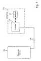
- FIG. 1illustrates an example embodiment of the invention.
- electronic device 104connects to an accessory 112 via a cable 108 .
- the electronic device 104may comprise any type of electronic device as may be contemplated by one of ordinary skill in the art. Examples of electronic devices that may benefit from the principles described herein include, but are not limited to, communication devices, personal digital assistants, cellular telephones, wireless communication devices, digital and analog data and voice recorders, sensors, pagers, watches, video display devices, audio devices, digital cameras, video recorders, or any other portable electronic device. It is contemplated that the electronic device 104 be configured to interface with an accessory 112 .
- the cable 108facilitates exchange of data and electrical signals between the electronic device and the accessory.
- any type channel or information exchange system or mediummay be implemented without departing from the scope of the invention.
- the cable 108may comprise any number or type of wire(s) or fiber(s) capable of carrying electrical signals or information.
- the cablemay be replaced with a wireless channel, such as radio or other frequency energy or free space optics.
- the accessorymay comprise any type accessory for use with any of the above-described variety of electronic devices.
- the accessory 112includes a controller 116 in communication with memory 120 .
- the controller 116includes an external connection 110 for connection to systems external to the accessory 112 .
- the controller 116may comprise any type of controller, control logic, ASIC, processor or any other type device or system configured to facilitate interface between the electronic device 104 and the memory 120 .
- the cable 108 or a portion of the cableconnects directly to the memory.
- the memory 120comprises any type data storage system capable of storing data, software code, control instructions or other information.
- the memory 120may comprise RAM, ROM, flash memory, disk drive, micro-drive, EPROM, magnetic memory, optical memory, CD or DVD memory. Any amount of memory 120 may be placed in the accessory. In one embodiment the accessory contains one to five kilobits of memory 120 . In other embodiments, any amount of data may be stored on the accessory.
- the memory 120stores control data configured to interface the electronic device 104 with the accessory. In one embodiment the controller 116 and memory 120 are integrated into a single system. Control data is defined herein to mean any data that aids, guides, assists, or controls interaction or operation between the accessory 112 or electronic device 104 .
- the control datamay include data that controls accessory or electronic device operation or interaction or software code or software patches or updates and may optionally be encapsulated within a packet and may include execution or activation instructions.
- Accessory interactionis defined herein to mean the operations, communication, or interface that occurs between an accessory and an electronic device prior to, during and after their use together. Examples of aspects or information that may be controlled or provided by control data, includes but is not limited to, echo canceler operations such as tuning parameters, the number of multipaths, the echo intensity, filter settings or coefficients, noise reduction system operation parameters and duration of operation, volume settings and number of steps, volume power levels, the tone or frequence response of a device, stereo mute options, volume tables.
- the control datadictates how a communication device interacts with or handles an accessory.
- the control datadefines the address mapping of an accessory memory or a register.
- the electronic device 104In operation it is desired to interface the electronic device 104 with the accessory 112 .
- the electronic device 104is energized. Thereafter the accessory 112 attaches to the electronic device 104 and the electronic device attempts to detect the type of accessory or determine how to interface with the accessory. This process is described below in more detail.
- the accessory 112overcomes the drawbacks of the prior art by storing the control data on the accessory 112 .
- the control datamay be associated with accessory 112 in any manner and in one embodiment the control data is stored in the memory 120 .
- Storing the control data in the memory 120provides the advantage of insuring the proper control data is with the particular accessory 112 and that the electronic device 104 has access to the control data. This also reduces the amount of memory required in the electronic device thereby reducing the cost of each electronic device 104 . Through interface between the electronic device 104 and the accessory 112 over the cable 108 the electronic device gains access to the control data.
- FIG. 2illustrates a block diagram of an example embodiment of a memory equipped wireless communication device accessory.
- a communication device 204connects to an accessory 212 via a conductor 208 .
- the accessory 212comprise a speaker phone system, such as a hands free system and the conductor 208 comprises a four conductor bus.
- the conductor 208may comprise any number of lines and the accessory 212 may comprise any type of accessory.
- Example accessoriesinclude but are not limited to, a speaker phone system for an automobile, a hands free ear piece, a car adapter battery charger, a charging cradle, or an interface module for interfacing the telephone with other electronic devices.
- the communication device 204includes a processor 216 that connects to the conductor 208 .
- the processor 216is in communication with memory 218 and configured to interface the communication device 204 with the accessory 212 .
- the processor 216may comprise any type processor, controller, ASIC, or control logic as could be used to interface the accessory 212 with the communication device 204 or oversee operation of the communication device.
- the communication device memory 218may comprise any type of data storage device. In one embodiment the processor 216 and the memory 218 operate in unison such that the memory stores data, software code, or both configured for use or execution by the processor as may be required.
- a tranceiver (Tx/Rx) 219connects to an antenna 217 and the processor 216 .
- the accessory 212is configured as a hands free accessory such as may be installed in an automobile for use with a cellular telephone or other communication device.
- the accessory 212includes a controller 220 , memory 224 , and an audio interface 228 .
- the memory 224interfaces with the controller 220 or, in one embodiment interfaces with the two lines 232 . It is contemplated that some form of controller 220 may be included to oversee access to the memory 224 .
- the memory 224includes an internal controller and hence the controller 220 would be eliminated or incorporated into the memory 224 . Such a configuration is contemplated for any embodiment or figure where a memory or controller is discussed or shown.
- the two lines 232 of the conductor 208connect to controller 220 and two lines 236 of the conductor connect to an audio interface 228 .
- the audio interface 228may comprise any type of device capable of assisting operation of audio systems such as those shown and described herein.
- the audio interface 228comprises a CODEC.
- the audio interface 228comprises an audio amplifier.
- the audio informationmay be provided to the communication device in analog or digital format.
- the controller 220 and audio interface 228may communicate or exchange data over any type of connection as shown.
- the conductors 232comprises an I 2 C bus.
- the I 2 C busprovides a low overhead data interface system for use with a limited number of conductors, in this example embodiment two.
- Any type conductor 232 , bus, or memory systemmay be used including, but not limited to, Dallas type bus system, such as the Dallas 1 wire conductor, SPI bus, multibus, 2WB, any type of serial bus, parallel bus, a PCM bus or any other type of bus or data transfer system or protocol.
- the controller 220further includes an external connection 250 configured to interface or connect the accessory 212 to a separate system or power supply. The external connection 250 of the accessory 212 facilitates interaction and interface with other systems or devices.
- an external connection 250is shown, including of an external connector is optional and is dependant of the needs of the accessory and electronic device.
- the accessory 212is a hands-free system or speaker phone system for use in an automobile and the electronic device 204 comprises a wireless communication device.
- the terms hands-free system or speaker phoneare defined herein to mean devices that allow a user to communicate over a communication device, such as a telephone, without the user physically holding a the communication device to their ear.
- the optional external connection 250may comprise a connection to the automobile's power supply, a connection to the automobile's ignition system, or a connection the automobile's radio for volume control.
- the accessory 212 and electronic device 204assume other forms the use and configuration of the external connection 250 may vary.
- the processor 216 and memory 218 of the communication device 204interface via the conductor 208 with the accessory 212 to provide speaker phone operation. It is contemplated that the processor 216 utilize control data regarding the type of accessory 212 to which it is attached and regarding how to interface with the accessory. In one embodiment one or more of the audio interface 228 , controller 220 , and processor 216 may perform echo cancellation or other complex processing on a signal to achieve desired operation.
- the control data that controls such operationare desirably stored in the memory 224 of the accessory 212 .
- the control data stored in the accessory 212may be accessed via the conductor- 232 by the communication device 204 to control operation between the two systems.
- storing the control data on the accessory 212provides the advantages of reducing the storage requirement on the communication device 204 , insuring updated and tailored control data for use with the accessory, providing flexibility for future use of different components in the accessory which may necessitate the use of modified control data.
- the audio interface 228also connects to a microphone 240 and a speaker 244 .
- Any type microphone 240 and speaker 244may be utilized. It is understood that microphones and speakers posses individual and unique performance characteristics. It is desired to accommodate these unique performance characteristics to achieve desired operation.
- control datathat defines the microphone and speaker behavior in the accessory 212 the proper control data is present for use by the communication device 204 .
- FIG. 3illustrates a block diagram of a feed forward echo cancellation system.
- FIG. 3 and the discussion that followsillustrates the benefit of matched control data in the accessory.
- an audio output line 304connects to a speaker 308 and a filter 312 .
- the filter 312also receives filter coefficients over input 314 , which may be determined in part by the control data. By providing optimized control data, such as those stored on the accessory, the filter is optimized for the particular speaker 308 and microphone pair 320 . This provides a more clear output than generic equalizer coefficients.
- the filter 312provides an output to a summing junction 324 .
- the filter 312provides its output to the summing junction 324 . It may be provided as a positive or negative input.
- the summing junction 324also receives an input signal from the microphone 320 .
- the output of the summing junction 324is provided to a communication device (not shown) for processing.
- the output signalis sent to the speaker 308 and filter 312 on line 304 .
- the speakergenerates an audible signal shown by line 330 .
- the microphone 320 of the hands free unitreceives a voice signal 338 for processing by the hands free system.
- the microphone 320also receives an echo wave 334 reflected back from surface 332 .
- the echo wave 334interferes with desired speaker phone operation by providing an echo signal for amplification as a received signal.
- the filter 312receives the signal on line 304 and feeds forward a signal to be subtracted from the microphone 320 output to thereby eliminate or reduce the reflection echo 334 .
- the filterutilizes specific filter coefficients, which are determined by the speaker, microphone, and accessory configuration. As a result of storing or associating the control data with the accessory, the communication device and accessory are best able to operate in an intended manner and reduce the echo.
- FIG. 4illustrates a block diagram of an example embodiment of an accessory 400 with the memory 412 separate from the controller 408 .
- data bus lines 404connect to a micro-controller 408 and a memory 412 for the exchange of data between the micro-controller 408 , the memory 412 , and an electronic device (not shown).
- the memory 412is separate from the micro-controller 408 .
- the memory 412 and micro-controller 408communicate and an external interface 420 connects to the micro-controller.
- the memory 412stores information, settings, data, or software code, collectively control data, that achieve desired operation of the accessory 400 with the electronic device.
- FIG. 5illustrates a block diagram of an example embodiment of an accessory 500 with a storage register 524 .
- data bus lines 504connect to a micro-controller 508 and a memory 512 for the exchange of data between the micro-controller 508 , the memory 512 , and an electronic device (not shown).
- the memory 512is separate from the micro-controller 508 .
- the memory 512 and micro-controller 508communicate over a channel and an external interface 520 connects to the micro-controller.
- the memory 512stores information, data, settings, or software code, collectively control data, that achieve desired operation of the accessory 500 with the electronic device.
- the register 524is in communication with the micro-controller 508 and bus 504 .
- the register 524may comprise any type storage unit configured to store one or more bits of data.
- the storage register 524stores data that defines or controls certain aspects of operation for the micro-controller 508 . It is desired to make the accessory 500 self-defining and operable with numerous electronic devices without need of data stored on the electronic device.
- the register 524stores data regarding the particular configuration or connection of the accessory at the time of use.
- the register 524stores data regarding the address of relevant data in the memory 512 .
- the register 524stores data regarding stereo mute status.
- stereo mute status datacomprises data regarding whether the stereo is muted, i.e. the stereo volume is set to zero, such as may be desired when speaking on at hands-free telephone in an automobile.
- the register 524may store any other type data.
- the register 524may comprise control logic.
- the control logicwould store or indicate the status of an aspect of operation as discussed above regarding the register 524 .
- the register 524 or control logiccould control the accessory without use of any other device or system.
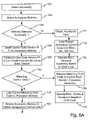
- FIG. 6Aillustrates an operational flow diagram of an example method of operation of one embodiment of the invention.
- Use of this method or a related methodallows a communication device and accessory to enjoy the advantages and benefits of control data storage on the accessory.
- This methodcould apply to any electronic device and accessory.
- the operationdetects the accessory. Any method of accessory detection may be used. One example method off detection is discussed below in greater detail.
- the operationattempts to access the memory on the accessory. This may be considered a memory read or memory detection operation. It is contemplated that not all accessories will include memory, such as for example older accessories that are not configured to store control data.
- the operationdetermines if the memory detection was successful. If the memory detection was not successful, the operation advances to a step 712 .
- the memory detectionmay be unsuccessful for a reason other than a non-memory equipped accessory.
- the operationdetects the accessory type. Any type of detection may occur and is performed to aid the communication device as to how to interact with the accessory. Thereafter, the operation advances to a step 716 and the electronic device retrieves for use from its memory default control data for use by the processor of the electronic device. While the default data may not be the preferred control data, it may enable operation of the accessory, albeit at a potentially lower level of quality. After loading the default control data for use by the electronic device, the operation advances to a step 720 and the electronic device and accessory operate in the best manner possible considering non-preferred control data may be in use.
- control data version IDbe stored in the memory of the accessory and identify the version or format of the control data that is stored on the accessory.
- each different control data, or version thereofreceives a different version ID.
- version IDalso identifies the exact type of accessory.
- a first memory location 780contains a control data version ID.
- the control data version IDidentifies the control data.
- a second memory location 784may contain a device ID code. The device ID code may identify which type of device the accessory comprises.
- a third memory location 788may contain device serial number that identifies the accessory. The device ID and device serial number may be included to aid identification of the device or tracking of the device. Any other or additional information may be stored at other memory locations to aid in data transfer, or accessory or control data identification. It is contemplated that a communication device may be programmed to automatically read or detect memory location 780 .
- a memory location 792stores the control data. In another embodiment the memory location 792 stores an address or pointer to the control data.
- step 728a comparison occurs between the control data version ID read from the accessory memory and control data version IDs that are stored on the electronic device.
- Each control data versionmay be provided a unique control data ID used to identify the control data. This ID can be used to quickly and efficiently compare versions, i.e. the contents, of a control data.
- the electronic deviceperforms the comparison while in another embodiment the accessory includes apparatus to perform the comparison.
- the control data that is stored on the electronic device and that has a matching control data version IDis recalled from the electronic device memory for use by the electronic device.
- the matching control datais loaded to a processor memory for use by a processor.
- the electronic device and the accessoryoperate and interface based on the matching control data.
- step 744the electronic device loads the control data from the electronic device that is most similar to the control data stored on the accessory and identified by the version ID.
- the control datais loaded from the non-volatile memory of the electronic device to the memory associated with a processor. The electronic device may initiate operation at this point using the control data.
- the operationaccesses the accessory memory to read the control data stored on the accessory memory.
- a electronic device/accessory interfaceto facilitate exchange of data, such as control data, between the electronic device and the accessory.
- the interfacecomprise a controller, a processor, or control logic.
- the closest match control data in the electronic device processor memoryis updated by the control data downloaded from memory. In this manner the processor memory is updated to contain the control data that is stored on the accessory.
- the comparison and update processresults in only the portions of the control data in the accessory that are different than the closest match control data being transferred to the electronic device.
- the electronic devicemay initiate operation at this point using the updated control data.
- the processor memorycontains the updated control data that is specifically tailored for the accessory, it may be desired to save the control data to a non-volatile memory of the communication device. Accordingly, at a decision step 760 it is determined if the electronic device has sufficient memory space available to store the updated control data under the corresponding control data version ID. It is contemplated that the updated control data will be stored in non-volatile memory so that if the accessory is used with the electronic device in the future the electronic device will contain a match to the control data version ID that is associated with the accessory. Thus, the above-described update process would not have to occur every time the accessory is connected.
- step 760If at step 760 it is determined that memory space is not available then the operation advances to a step 764 and the communication device deletes non-default control data stored in its memory. In one embodiment the deletion occurs on a least recently accessed—first deleted basis such that the control data that was accessed least recently is the first to be deleted.
- step 760 or 764the operation advances to a step 768 wherein the operation saves the updated version of the control data in the electronic device memory. This insures that the control data that is specifically tailored to the accessory is available for use in the future if the accessory is attached or used with the electronic device.
- step 772the electronic device and accessory operate and interact based on the updated control data. This provides the advantage of having the control data specifically designed for the accessory available for use with the electronic device.
- FIG. 8illustrates an operational flow diagram of an alternative method of operation.
- the method of operation shown in FIG. 8is a method of operation in which the control data of the accessory is loaded to the electronic device from the accessory at start-up each time the accessory is used with the electronic device.
- the methodmay be initiated by detecting the accessory at a step 800 and, at a step 804 , attempting to detect the accessory memory.
- the electronic devicedetermines if control data is available on the accessory. Accordingly, at a decision step 808 the operation determines if the memory detection was successful. If memory was not detected then the operation advances to step 812 and the operation detects the type of accessory attached to the electronic device.
- the electronic deviceloads default or best-match control data for the detected accessory from the non-volatile memory of the electronic device. This occurs at a step 816 . Thereafter, at step 820 , the electronic device and the accessory interact based on the default control data.
- step 824comprises accessing the control data from accessory memory.
- step 824comprises accessing the control data from accessory memory.
- the operationloads the accessory control data to the electronic device.
- the control datais loaded to a memory associated with a processor in the electronic device. After the control data is loaded in the electronic device the electronic device and the accessory may interact and operate in a manner based on the transferred control data.
- the method and apparatus described hereinis adapted to facilitate use of an accessory as a demo-device.
- the control datamay be configured to allow use of the accessory for a limited period of time or for a limited number of uses. After the number of uses or the period of time has been exceeded, the accessory may cease to operate or provide an audio or visual message regarding the reason for non-use and where to purchase a non-demo version of the accessory. In such an embodiment the accessory may be given away or at a discount to lure potential purchasers to buy the accessory after the demo period is expired.
- control datamay include a security code or other security information or means to control or limit use of the accessory. This may reduce theft or instances of stolen communication services.
- control datamay comprise security codes or accesses codes that are stored in the accessory memory to inhibit use of counterfeit or un-licensed accessories with the electronic device.
- the method and apparatus described hereinis adapted to assist in debugging of an accessory or determining a source of error with an accessory or communication device.
- the memory on the accessorymay be made to store data regarding accessory operation or communication device operation. By storing this data on the accessory that is equipped with memory the accessory may be configured as a debugging tool to which data is stored.
- the debugging accessorymay be provided to technical personnel for use in determining problems with electronic device, beta testing, or monitoring use of a telephone. With regard to monitoring, data may be written to the accessory memory to monitor call usage or duration, such as in a rental or loaner telephone.
- the accessorymay be equipped to store and track billing data for a limited use telephone or other type electronic device. It is contemplated that an accessory may store a prepaid dollar amount and track usage while subtracting from the dollar amount in relation to use of the telephone.
- the accessory equipped with memorymay be made to enhance the feature set of the telephone.
- the memory equipped accessoryincluded software code and processing capability to perform encryption and decryption on incoming and outgoing data or calls.
- one embodimentincorporates accessory detection capability to thereby speed operation and initialization of an accessory when connected to an electronic device.
- the accessory detection method and apparatus described hereinprovides important information to the electronic device regarding the type of accessory that is connected to the electronic device.
- the electronic device's manner of operation and interaction with the accessoryis determined, at least in part, by the type of accessory to which it is connected. Therefore, ascertaining the type of accessory connected to the electronic device in a rapid, efficient, and accurate manner provides an advantage to accessory interface.
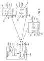
- FIG. 9illustrates a block diagram of an exemplary manner of interaction between an electronic device and various accessory types.
- the electronic device 904comprises electronic systems and detector 908 connected to a first input 912 and a second input 916 . Although shown with two inputs 912 , 916 , it is contemplated that more than two inputs may be provided. While the first and second inputs 912 , 916 are contemplated for use as data transfer bus lines it is also contemplated that additional conductors 920 may be provided to exchange information such as voice information.
- first and second inputs 912 , 916Although described herein as the first and second inputs 912 , 916 , it is contemplated that the first and second inputs will also serve as outputs to the accessory during the interface stage of operation.
- the terms first input 912 and second input 916were selected to aid in understanding as in one embodiment during the detection phase the inputs 912 , 916 receive signals, such as a DC voltage level.
- the accessorymay not be powered and hence unable to provide a signal to the electronic device.
- the electronic device inputs 912 , 916may serve as outputs and output a signal or voltage level to an accessory.
- the accessorywill be configured to respond or accept the signal in a manner that is unique to the particular type of accessory.
- the electronic device 904is able to detect how the accessory responds or accepts the signal. In this manner the type or class of accessory may be detected.
- Those of ordinary skill in the artare aware of accessory configurations that cause the accessory to respond or accept the signal in a way that will identify the type of class of accessory.
- first accessory 924includes a first output 936 and a second output 940 .
- the first output 936connects to ground through a resistor 937 while the second output 940 connects to a voltage source V+.
- a resistor 942is serially connected between the second output 940 and the voltage source V+.
- a first output 944connects to a voltage source V+ and a second output 946 connects to ground through a resistor 947 .
- a resistor 948may be serially connected between the first output 944 and a voltage source V+.
- the third accessory type 932includes a first output 950 and a second output 952 .
- the first and second output 950 , 952connect to a voltage source V+.
- resistors 954 , 956connect serially between the outputs 950 and 952 and the voltage source V+.
- the outputs of the first accessory type 924 , the second accessory type 928 , or the third accessory type 932may connect to the inputs 912 , 916 of the electronic device 904 .
- Each of the accessory types 924 , 928 , 932represent a type or class of accessories.
- an accessory typemay share some commonality in the way the electronic device 904 interacts or operates when connected to an accessory type.
- the electronic device 904comprises a wireless communication device and the first accessory type 924 may comprise devices that perform charging, the second accessory type 928 may comprise devices that provide audio to the communication device yet lack memory, and the third accessory type 932 may comprise smart accessories, which are defined herein to mean accessories with memory that store control data.
- the outputs 936 , 940 , 944 , 946 , 950 , 952 of the accessories types 924 , 928 , 932may also serve as inputs to receive commands or signals from the electronic device 904 during interface phase of operation.
- the outputs 936 , 940 , 944 , 946 , 950 , 952provide a signal to the electronic device during the detection phase and hence for purposes of understanding are referred to as outputs during the accessory detection phase.
- the outputs 936 , 940 , 944 , 946 , 950 , 952may be configured to receive a signal from the electronic device. Hence, in certain embodiments or during certain phases of operation the outputs 936 , 940 , 944 , 946 , 950 , 952 may also serve as inputs. Hence the connection between an accessory and an electronic device is bi-directional.
- the detector 908Prior to connection of an accessory to the electronic device, the detector 908 monitors the inputs 912 and 916 . In one embodiment the detector 908 monitors for a voltage level from the accessory thereby not undesirably drawing power such as from a battery 909 from the electronic device 904 . Upon connection of the accessory to the electronic device 904 the detector 908 senses the connection by receiving a high voltage on one or more of its inputs 912 , 916 . The high voltage level is provided by one of the accessories 924 , 928 , or 932 that is connected to the electronic device. The detector 908 may provide data to the processor 910 regarding which lines are high and the processor may compare the line voltage pattern to a known pattern or simply analyze the line voltage pattern. Based on the comparison or analysis a determination can be made as to the type of accessory 924 , 928 , 932 connected to the electronic device 904 .
- the electronic device 904may initiate one or more different interface routines or operations.
- the accessory typeis determined to be a battery charging type accessory then the electronic device 904 may prepare for charging and begin displaying charging information on its screen.
- the accessoryis a smart accessory such that it includes control data stored on an accessory memory then the electronic device 904 may initiate a memory read from the accessory and begin the control data comparison or download process.
- Other accessory typesmay initiate different operations within the electronic device.
- One advantageis that it provides a low cost system for detecting when an accessory is connected. Another advantage is that it provides a method and apparatus to detect a type or class of accessory connected to the electronic device. Another advantage comprises that it draws little to no power during operation. Further advantage is that it is expandable to more than two conductors. A single conductor or more than two conductors may be enabled.
- FIG. 10illustrates an example implementation of an example embodiment of the accessory detection system. This is but one possible implementation. One of ordinary skill in the art may contemplate other configurations that do not depart from the scope of the claims.
- An electronic device 1004is represented on the left hand side of the page while an accessory 1008 is represented on the right hand side of the page. Although not required, in the embodiment of FIG. 10 , the accessory 1008 includes memory 1012 .
- the electronic device 1004include a serial clock input 1020 and a serial data input 1022 .
- Resistors 1034 , 1036connect as shown to the inputs 1030 , 1032 .
- the span or gap 1040may comprise a cable or conductor.
- the span 1040may be of any length or simply comprises a contact on a device, such as a contact on a charger.
- Accessory outputs 1044 , 1046connect to the electronic device 1004 .
- the outputs 1044 , 1046connect to resistors 1050 , 1052 , both of which connect to a voltage source V+.
- the voltage sourcemay comprise any type voltage source including a battery or a hardwired source or combination thereof.
- the outputs 1044 , 1046further connect to a controller 1070 , a processor, control logic, or hardwired to a voltage source or ground. In the embodiment shown in FIG. 10 , the controller 1070 is located in accessory memory 1012 . In operation the outputs 1044 and 1046 may be controlled to selectively manipulate the voltage levels thereon to be high or low values.
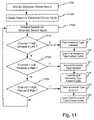
- FIG. 11illustrates an operational flow diagram of an example method of operation of an accessory detection system.
- FIG. 11illustrates an exemplary method of detecting an accessory connected to an electronic device with two conductors or channels, it is anticipated that any number of conductors may be used to connect an accessory to an electronic device and the method of detection described herein may be adapted to meet requirements of a varying number of conductors.
- an electronic devicemonitors its one or more inputs for an input signal. In one embodiment the inputs are receiving no signal or a zero voltage level when an accessory is not attached.
- the electronic devicemay be configured to communicate with an accessory over one or more conductors. To properly interact with the various different types of accessories it is desired to detect the type or category of accessory that is attached.
- the electronic devicedetects a signal on one or more of its inputs. Any type signal may be detected. In the method of FIG. 11 the signals comprise DC voltage levels. Thereafter, at a step 1108 the electronic device analyzes the signals. Any type analysis may be performed. In one embodiment the analysis comprises comparison of the signals to data stored in memory for a matching signal pattern. In another embodiment the analysis comprises presenting the signals on the one or more inputs to a logic network.
- the operationadvances to decision step 1112 .
- the operationdetermines if the first channel is high, i.e. presented with a voltage level, and the second channel is low, i.e. presented with no voltage. If decision step 1112 determines that the first channel is high and the second channel is low then the operation advances to step 1116 .
- the operationdetermines that a first accessory type has been detected. Because a first accessory type has been detected the operation advances to step 1118 wherein the electronic device prepares to interface with an accessory qualifying as a first accessory type. It is assumed that accessories falling into the category of a first accessory type share some similar interface routines. In one embodiment the electronic device loads control data that correspond to the first accessory type to guide or control interface with the accessory.
- the operationadvances to a decision step 1120 .
- the operationdetermines if the first channel is low while the second channel is high. If the first channel is low while the second channel is high, then the operation advances to a step 1124 .
- the operationdetermines that a second accessory type is connected to the electronic device.
- the electronic deviceprepares for interaction with the accessory, which was determined to be the second accessory type. In one embodiment this comprises loading control data that corresponds to the second accessory type. It is contemplated that any action may be taken.
- the first accessory types and the second accessory typesdo not include a memory that is configured to stored control data.
- interaction with first accessory types and second accessory typesmay involve use of control data stored on the electronic device.
- the control datamay comprise interaction routines.
- the operationadvances to a decision step 1132 .
- the operationdetermines if the first channel is high and the second channel is high. If the first channel is high while the second channel is high, then the operation advances to a step 1136 .
- the operationdetermines that a third accessory type is connected to the electronic device.
- the electronic deviceprepares for interaction with the accessory, which was determined to be the third accessory type. In one embodiment this comprises reading data from the accessory memory, such as a control data version ID. It is contemplated that any action may be taken. One such action may comprise initiating the operation illustrated in FIG. 6 or 8 .
Landscapes
- Engineering & Computer Science (AREA)
- Signal Processing (AREA)
- Computer Networks & Wireless Communication (AREA)
- Human Computer Interaction (AREA)
- Telephone Function (AREA)
Abstract
Description
The present invention relates to communication device accessories and in particular to communication device accessory interface and detection.
Portable electronic devices are popular devices used by individuals to track and store data, manage information, and communicate with other electronic devices. Examples of portable electronic devices include personal display adapters, cellular telephones, wireless communication devices, digital and analog data and voice recorders, sensors, pagers, watches, video display devices, audio devices, digital cameras, video recorders, or any other portable electronic device.
As with most electronic devices in use today there exist a wide array of available accessories to enhance the electronic device. By way of example, for a cellular telephone the available accessories may include, but are not limited to, a speaker phone system for an automobile, a hands free ear piece, a car adapter battery charger, a charging cradle, or an interface module for interfacing the telephone with other electronic devices. As is understood, it is necessary for the electronic apparatus of the telephone to interface with the accessory. Such interface is often controlled by software that instructs the telephone how to interface with the accessory.
In systems of the prior art the electronic device stored the software that controls interaction between the electronic device and the accessory. This presents many drawbacks which the methods and apparatus disclosed herein overcome. One such drawback is that the telephone has a limited amount of memory and is hence limited in the amount of data that can be stored. Hence, the cost of each telephone increases as a result of additional memory in each telephone or, if memory is minimized, the amount of information that can be stored in the telephone is limited. Both of these options are considered undesirable.
Another drawback of systems of the prior art arises as a result of the timing of when a user obtains a telephone and when a user obtains an accessory. In systems of the prior art, the telephone stored all the information necessary for interaction with an accessory. As a result, the data that oversaw accessory operation was stored in the phone at the time the phone leaves the manufacturing plant or when the phone is sold. Consequently, if the data for an accessory changed or if a new accessory with new data was released after purchase of the telephone the telephone will not contain the new data. As a result, the accessory may not be operable with the telephone or the telephone may have to use a generic or default data which may provide poor performance. Some accessories require complex filter control data and thus, failure to utilize an up to date data during accessory interaction is a considerable drawback.
Yet another drawback that arises from storing data on the telephone is that the telephone release date may be delayed while the accessory data is created and tested. As can be understood, a delay in the release date may result in substantial lost profits and a reduction in market share.
Yet another drawback of electronic devices of the prior art is difficulty in determining when an accessory is attached and determining how to interact with an accessory. As can be understood, one aspect of accessory interaction comprises determining when to initiate an interaction process and which interaction process to initiate.
As with most electronic device in use today there exist a wide array of available accessories to enhance the electronic device. By way of example, for a cellular telephone the available accessories may include, but are not limited to, a speaker phone system for an automobile, a hands free ear piece, a car adapter battery charger, a charging cradle, or an interface module for interfacing the telephone with other electronic devices. As is understood, for the electronic apparatus to successfully operate with the cellular telephone, some form of interface between the accessory and the telephone is necessary. The interface, which may comprise a hardware system, is often controlled or assisted by software that instructs the telephone how to interface with the accessory. At other times data was passed to the accessory from the telephone during operation.
Systems of the prior art utilized a digital interface between the telephone and the accessory for exchange of voice data or upload of accessory data from the telephone to the accessory. The accessory data traveled on the same channel between the accessory and the telephone as was used for exchange of voice information. This presented many problems and drawbacks. One such drawback of using a shared channel is that the channel was often bandwidth limited. Hence, the channel's limited capacity prevented the free exchange of data from the telephone to the accessory to control the interface. Another drawback was that channel conflicts, between the voice information and the interface data, could arise. These conflict prevented desired operation.
Another drawback of prior art systems is their high cost. The prior art method and apparatus used to detect the type of accessory attached to the electronic device required expensive and complex hardware and software detection systems. This cost, when multiplied by a large number of telephones, undesirably reduces profits or increases the cost to the consumer of the electronic device.
Yet another drawback of the prior art accessory detection is that a user's ability to hot-swap an accessory may be limited. In some prior art wireless communication devices a single channel was utilized for both accessory interface and voice communication. Thus, in the case of a wireless communication device the user may not be able to remove the wireless device from an automobile speaker phone system and continue the call with a earphone system after leaving the car. This is an example of a hot-swap operation. An inability to perform a hot-swap operation can be considered a major disadvantage and limit the intended purpose of a portable communication device.
Thus, there exists a need for a method and apparatus to overcome these drawbacks in the prior art. The method and apparatus disclosed herein overcomes these drawbacks.
The method and apparatus described herein overcomes the problems and drawbacks associated with the prior art by providing an efficient and rapid method to insure the proper control data is available for use by a electronic device, such as a communication device, to properly interface with an accessory. In systems of the prior art the electronic device is sold with pre-stored control data loaded into the memory of the electronic device. Over time however, new accessories are introduced or existing accessories are modified or improved. The new or modified accessories may have new or modified control data that is tailored for use with the new or modified accessory. As a result, the pre-stored control data on the electronic device is no longer the most up to date control data. A default, or best match control data stored on the electronic device often had to suffice. Failure, by prior art systems, to use the most up to date control data resulted in inferior performance or incompatibility.
The present method and apparatus overcomes the drawbacks associated with the prior art by associating or storing the control data with the accessory. Accordingly, the accessory includes memory configured to store the control data and interface with an electronic device. This provides the advantage of the most current control data, which is tailored for the accessory, always being associated with the accessory and available for use by an electronic device that may connect to the accessory. New accessories may be released, after the release or purchase of the electronic device, that contain the most up to date control data. In addition, if the accessory must be modified, the control data may also be updated to account for the modification.
In one embodiment the control data is stored in a nonvolatile memory and identified by a version ID. The term nonvolatile memory comprises a memory whose stored data is undisturbed by removal of operating power. The control data may be downloaded or transferred to the electronic device for use by the electronic device to guide operation of and interface with the accessory. In one embodiment the electronic device comprises a wireless telephone and the accessory comprises a hands free system for use in an automobile. In such an embodiment the telephone may include a processor and the accessory may include a memory or a controller, or both. A bus, such as a four conductor bus may interface the accessory to the telephone and be made available for transfer of control data to the telephone if necessary.
In one embodiment the telephone may access the accessory memory to obtain information regarding the control data and the accessory. In one embodiment the control data on the accessory is identified by a version ID. The telephone compares the control data version ID obtained from the accessory to control data version ID's stored in the telephone memory. If a matching version ID is found, then the control data associated with that version ID is selected for use with the accessory.
In one embodiment a method and apparatus is provided for accessory detection and identification. In one configuration the accessory includes one or more outputs, such as conductors or terminals. The electronic device includes corresponding input terminals for connection to the accessories output. The electronic device monitors its input terminals for a change in voltage level, such as for a signal. Upon detection of a signal, a determination can be made that an accessory is attached. In addition, analysis of the output signals or input pattern occurs to identify a type of accessory connected to the electronic device. By detecting a type or category of accessory that is connected to the electronic device, the electronic device may take the appropriate action to interface with the accessory.
If a matching version ID is not found then the telephone processor initiates a download process to obtain the correct control data as stored on the accessory. In one embodiment the downloaded control data is stored in the nonvolatile memory of the telephone for use the next time the telephone interfaces with the accessory. In one embodiment the control data is not stored and the download process occurs every time the accessory is connected to the telephone.
In one embodiment the accessory is further configured with a storage register. The register is configured to store one or more bits of data. In one embodiment the bits of data serve as flags to be read by the electronic device to communicate the settings of the accessory. In one embodiment the accessory comprises a hands free system and the registers store data regarding whether the mute is set or whether the radio is on.
A method and apparatus for accessory detection and interface is disclosed. In the following description, numerous specific details are set forth in order to provide a more thorough description of the present invention. It will be apparent, however, to one skilled in the art, that the present invention may be practiced without these specific details. In other instances, well-known features have not been described in detail so as not to obscure the invention.
In the example embodiment shown inFIG. 1 , theaccessory 112 includes acontroller 116 in communication withmemory 120. Thecontroller 116 includes an external connection110 for connection to systems external to theaccessory 112. Thecontroller 116 may comprise any type of controller, control logic, ASIC, processor or any other type device or system configured to facilitate interface between theelectronic device 104 and thememory 120. In one embodiment thecable 108 or a portion of the cable connects directly to the memory.
Thememory 120 comprises any type data storage system capable of storing data, software code, control instructions or other information. Thememory 120 may comprise RAM, ROM, flash memory, disk drive, micro-drive, EPROM, magnetic memory, optical memory, CD or DVD memory. Any amount ofmemory 120 may be placed in the accessory. In one embodiment the accessory contains one to five kilobits ofmemory 120. In other embodiments, any amount of data may be stored on the accessory. In one embodiment thememory 120 stores control data configured to interface theelectronic device 104 with the accessory. In one embodiment thecontroller 116 andmemory 120 are integrated into a single system. Control data is defined herein to mean any data that aids, guides, assists, or controls interaction or operation between the accessory112 orelectronic device 104. The control data may include data that controls accessory or electronic device operation or interaction or software code or software patches or updates and may optionally be encapsulated within a packet and may include execution or activation instructions. Accessory interaction is defined herein to mean the operations, communication, or interface that occurs between an accessory and an electronic device prior to, during and after their use together. Examples of aspects or information that may be controlled or provided by control data, includes but is not limited to, echo canceler operations such as tuning parameters, the number of multipaths, the echo intensity, filter settings or coefficients, noise reduction system operation parameters and duration of operation, volume settings and number of steps, volume power levels, the tone or frequence response of a device, stereo mute options, volume tables. In one embodiment the control data dictates how a communication device interacts with or handles an accessory. In one embodiment the control data defines the address mapping of an accessory memory or a register.
In operation it is desired to interface theelectronic device 104 with theaccessory 112. At start-up, theelectronic device 104 is energized. Thereafter theaccessory 112 attaches to theelectronic device 104 and the electronic device attempts to detect the type of accessory or determine how to interface with the accessory. This process is described below in more detail. In one embodiment it is desired to obtain data, such as control data, or have such data available, to control interface between the accessory112 andelectronic device 104. In one embodiment theaccessory 112 overcomes the drawbacks of the prior art by storing the control data on theaccessory 112. The control data may be associated withaccessory 112 in any manner and in one embodiment the control data is stored in thememory 120. Storing the control data in thememory 120 provides the advantage of insuring the proper control data is with theparticular accessory 112 and that theelectronic device 104 has access to the control data. This also reduces the amount of memory required in the electronic device thereby reducing the cost of eachelectronic device 104. Through interface between theelectronic device 104 and theaccessory 112 over thecable 108 the electronic device gains access to the control data.
This configuration is shown for purposes of discussion only and the claims that follow should not be considered to be limited to this embodiment. It is contemplated than numerous other configuration may be arrived at by one of ordinary skill in the art that are able to achieve the benefits described herein by storing or associating interface data or control data in the accessory.
Thecommunication device 204 includes aprocessor 216 that connects to theconductor 208. Theprocessor 216 is in communication withmemory 218 and configured to interface thecommunication device 204 with theaccessory 212. Theprocessor 216 may comprise any type processor, controller, ASIC, or control logic as could be used to interface theaccessory 212 with thecommunication device 204 or oversee operation of the communication device. Thecommunication device memory 218 may comprise any type of data storage device. In one embodiment theprocessor 216 and thememory 218 operate in unison such that the memory stores data, software code, or both configured for use or execution by the processor as may be required. A tranceiver (Tx/Rx)219 connects to anantenna 217 and theprocessor 216.
In the embodiment shown inFIG. 2 , theaccessory 212 is configured as a hands free accessory such as may be installed in an automobile for use with a cellular telephone or other communication device. Theaccessory 212 includes acontroller 220,memory 224, and anaudio interface 228. Thememory 224 interfaces with thecontroller 220 or, in one embodiment interfaces with the twolines 232. It is contemplated that some form ofcontroller 220 may be included to oversee access to thememory 224. In another embodiment thememory 224 includes an internal controller and hence thecontroller 220 would be eliminated or incorporated into thememory 224. Such a configuration is contemplated for any embodiment or figure where a memory or controller is discussed or shown.
In the example embodiment shown the twolines 232 of theconductor 208 connect tocontroller 220 and twolines 236 of the conductor connect to anaudio interface 228. Theaudio interface 228 may comprise any type of device capable of assisting operation of audio systems such as those shown and described herein. In one embodiment theaudio interface 228 comprises a CODEC. In one embodiment theaudio interface 228 comprises an audio amplifier. Hence, the audio information may be provided to the communication device in analog or digital format. Thecontroller 220 andaudio interface 228 may communicate or exchange data over any type of connection as shown.
In one embodiment theconductors 232 comprises an I2C bus. The I2C bus provides a low overhead data interface system for use with a limited number of conductors, in this example embodiment two. Anytype conductor 232, bus, or memory system may be used including, but not limited to, Dallas type bus system, such as theDallas 1 wire conductor, SPI bus, multibus, 2WB, any type of serial bus, parallel bus, a PCM bus or any other type of bus or data transfer system or protocol. Thecontroller 220 further includes anexternal connection 250 configured to interface or connect theaccessory 212 to a separate system or power supply. Theexternal connection 250 of theaccessory 212 facilitates interaction and interface with other systems or devices. Although anexternal connection 250 is shown, including of an external connector is optional and is dependant of the needs of the accessory and electronic device. In one exemplary embodiment theaccessory 212 is a hands-free system or speaker phone system for use in an automobile and theelectronic device 204 comprises a wireless communication device. The terms hands-free system or speaker phone are defined herein to mean devices that allow a user to communicate over a communication device, such as a telephone, without the user physically holding a the communication device to their ear. In such an exemplary embodiment the optionalexternal connection 250 may comprise a connection to the automobile's power supply, a connection to the automobile's ignition system, or a connection the automobile's radio for volume control. When theaccessory 212 andelectronic device 204 assume other forms the use and configuration of theexternal connection 250 may vary.
In operation, theprocessor 216 andmemory 218 of thecommunication device 204 interface via theconductor 208 with theaccessory 212 to provide speaker phone operation. It is contemplated that theprocessor 216 utilize control data regarding the type ofaccessory 212 to which it is attached and regarding how to interface with the accessory. In one embodiment one or more of theaudio interface 228,controller 220, andprocessor 216 may perform echo cancellation or other complex processing on a signal to achieve desired operation. The control data that controls such operation are desirably stored in thememory 224 of theaccessory 212. The control data stored in theaccessory 212 may be accessed via the conductor-232 by thecommunication device 204 to control operation between the two systems. As discussed above, storing the control data on theaccessory 212 provides the advantages of reducing the storage requirement on thecommunication device 204, insuring updated and tailored control data for use with the accessory, providing flexibility for future use of different components in the accessory which may necessitate the use of modified control data.
Theaudio interface 228 also connects to amicrophone 240 and aspeaker 244. Anytype microphone 240 andspeaker 244 may be utilized. It is understood that microphones and speakers posses individual and unique performance characteristics. It is desired to accommodate these unique performance characteristics to achieve desired operation. By storing the data, i.e. control data, that defines the microphone and speaker behavior in theaccessory 212 the proper control data is present for use by thecommunication device 204.
In operation the output signal is sent to thespeaker 308 and filter312 online 304. The speaker generates an audible signal shown byline 330. Simultaneously, themicrophone 320 of the hands free unit receives avoice signal 338 for processing by the hands free system. Undesirably however, themicrophone 320 also receives anecho wave 334 reflected back fromsurface 332. Theecho wave 334 interferes with desired speaker phone operation by providing an echo signal for amplification as a received signal.
In the embodiment ofFIG. 3 , thefilter 312 receives the signal online 304 and feeds forward a signal to be subtracted from themicrophone 320 output to thereby eliminate or reduce thereflection echo 334. To achieve proper operation however, the filter utilizes specific filter coefficients, which are determined by the speaker, microphone, and accessory configuration. As a result of storing or associating the control data with the accessory, the communication device and accessory are best able to operate in an intended manner and reduce the echo.
This is but one specific example of how an accessory and communication device will benefit from storing the control data in the accessory. Other inherent benefits are contemplated as other aspects of operation will also be improved.
Theregister 524 is in communication with themicro-controller 508 andbus 504. Theregister 524 may comprise any type storage unit configured to store one or more bits of data. In one embodiment thestorage register 524 stores data that defines or controls certain aspects of operation for themicro-controller 508. It is desired to make theaccessory 500 self-defining and operable with numerous electronic devices without need of data stored on the electronic device. In one embodiment theregister 524 stores data regarding the particular configuration or connection of the accessory at the time of use. In one embodiment theregister 524 stores data regarding the address of relevant data in thememory 512. In one embodiment theregister 524 stores data regarding stereo mute status. In one embodiment stereo mute status data comprises data regarding whether the stereo is muted, i.e. the stereo volume is set to zero, such as may be desired when speaking on at hands-free telephone in an automobile. In other embodiments, theregister 524 may store any other type data.
It is further contemplated that theregister 524 may comprise control logic. In such an embodiment the control logic would store or indicate the status of an aspect of operation as discussed above regarding theregister 524. Moreover, theregister 524 or control logic could control the accessory without use of any other device or system.
Since not all accessories include memory with control data stored thereon, at adecision step 708 the operation determines if the memory detection was successful. If the memory detection was not successful, the operation advances to astep 712. The memory detection may be unsuccessful for a reason other than a non-memory equipped accessory. Atstep 712 the operation detects the accessory type. Any type of detection may occur and is performed to aid the communication device as to how to interact with the accessory. Thereafter, the operation advances to astep 716 and the electronic device retrieves for use from its memory default control data for use by the processor of the electronic device. While the default data may not be the preferred control data, it may enable operation of the accessory, albeit at a potentially lower level of quality. After loading the default control data for use by the electronic device, the operation advances to astep 720 and the electronic device and accessory operate in the best manner possible considering non-preferred control data may be in use.
Alternatively, if the memory detect ofdecision step 708 was successful, the process advances to astep 724. Since the memory detect was successful, the accessory has memory and accordingly, atstep 724 the electronic device reads a control data version ID from the accessory memory. It is contemplated that the control data version ID be stored in the memory of the accessory and identify the version or format of the control data that is stored on the accessory. In one embodiment, each different control data, or version thereof, receives a different version ID. In one embodiment the version ID also identifies the exact type of accessory.
Jumping briefly toFIG. 7 , an example accessory memory unit is illustrated. In the example embodiment ofFIG. 7 afirst memory location 780 contains a control data version ID. In one embodiment the control data version ID identifies the control data. Asecond memory location 784 may contain a device ID code. The device ID code may identify which type of device the accessory comprises. Athird memory location 788 may contain device serial number that identifies the accessory. The device ID and device serial number may be included to aid identification of the device or tracking of the device. Any other or additional information may be stored at other memory locations to aid in data transfer, or accessory or control data identification. It is contemplated that a communication device may be programmed to automatically read or detectmemory location 780. Amemory location 792 stores the control data. In another embodiment thememory location 792 stores an address or pointer to the control data.
Returning to the operation ofFIG. 6 , after reading the control data version ID from the accessory memory the process advances to astep 728. At step728 a comparison occurs between the control data version ID read from the accessory memory and control data version IDs that are stored on the electronic device. Each control data version may be provided a unique control data ID used to identify the control data. This ID can be used to quickly and efficiently compare versions, i.e. the contents, of a control data. In one embodiment the electronic device performs the comparison while in another embodiment the accessory includes apparatus to perform the comparison.
At a decision step732 a determination is made regarding whether the electronic device contains in its memory a matching control data version ID, and hence a matching control data to that stored on the accessory. If the electronic device does contain a matching control data then the operation advances to astep 736. Atstep 736 the control data that is stored on the electronic device and that has a matching control data version ID is recalled from the electronic device memory for use by the electronic device. In one embodiment the matching control data is loaded to a processor memory for use by a processor. Thereafter, atstep 740 the electronic device and the accessory operate and interface based on the matching control data.
Alternatively, if atstep 732, a matching control data version ID is not stored on the electronic device then the operation advances to astep 744. Atstep 744 the electronic device loads the control data from the electronic device that is most similar to the control data stored on the accessory and identified by the version ID. In one embodiment the control data is loaded from the non-volatile memory of the electronic device to the memory associated with a processor. The electronic device may initiate operation at this point using the control data.
Thereafter, atstep 752 the operation accesses the accessory memory to read the control data stored on the accessory memory. This involves use of a electronic device/accessory interface to facilitate exchange of data, such as control data, between the electronic device and the accessory. In one embodiment the interface comprise a controller, a processor, or control logic. At astep 756 ofFIG. 6B , using a comparison or other analysis, the closest match control data in the electronic device processor memory is updated by the control data downloaded from memory. In this manner the processor memory is updated to contain the control data that is stored on the accessory. In one embodiment the comparison and update process results in only the portions of the control data in the accessory that are different than the closest match control data being transferred to the electronic device. The electronic device may initiate operation at this point using the updated control data.
Now that the processor memory contains the updated control data that is specifically tailored for the accessory, it may be desired to save the control data to a non-volatile memory of the communication device. Accordingly, at adecision step 760 it is determined if the electronic device has sufficient memory space available to store the updated control data under the corresponding control data version ID. It is contemplated that the updated control data will be stored in non-volatile memory so that if the accessory is used with the electronic device in the future the electronic device will contain a match to the control data version ID that is associated with the accessory. Thus, the above-described update process would not have to occur every time the accessory is connected. If atstep 760 it is determined that memory space is not available then the operation advances to astep 764 and the communication device deletes non-default control data stored in its memory. In one embodiment the deletion occurs on a least recently accessed—first deleted basis such that the control data that was accessed least recently is the first to be deleted.
Afterstep step 768 wherein the operation saves the updated version of the control data in the electronic device memory. This insures that the control data that is specifically tailored to the accessory is available for use in the future if the accessory is attached or used with the electronic device. After saving the updated version of the control data the operation advances to step772 and the electronic device and accessory operate and interact based on the updated control data. This provides the advantage of having the control data specifically designed for the accessory available for use with the electronic device.
Alternatively, if atstep 808 memory is detected then the operation advances to astep 824. Since the memory with control data stored therein is in the accessory,step 824 comprises accessing the control data from accessory memory. As a result the operation loads the accessory control data to the electronic device. In one embodiment the control data is loaded to a memory associated with a processor in the electronic device. After the control data is loaded in the electronic device the electronic device and the accessory may interact and operate in a manner based on the transferred control data.
It will be understood that the above described arrangements of apparatus and the method therefrom are merely illustrative of applications of the principles of this invention and many other embodiments and modifications may be made without departing from the spirit and scope of the invention as defined in the claims.
In one embodiment the method and apparatus described herein is adapted to facilitate use of an accessory as a demo-device. In such an embodiment the control data may be configured to allow use of the accessory for a limited period of time or for a limited number of uses. After the number of uses or the period of time has been exceeded, the accessory may cease to operate or provide an audio or visual message regarding the reason for non-use and where to purchase a non-demo version of the accessory. In such an embodiment the accessory may be given away or at a discount to lure potential purchasers to buy the accessory after the demo period is expired.
In another embodiment the method and apparatus described herein is adapted to incorporate a security layer into the accessory or interaction with the electronic device. In such an embodiment the control data may include a security code or other security information or means to control or limit use of the accessory. This may reduce theft or instances of stolen communication services. In addition, the control data may comprise security codes or accesses codes that are stored in the accessory memory to inhibit use of counterfeit or un-licensed accessories with the electronic device.
In another embodiment the method and apparatus described herein is adapted to assist in debugging of an accessory or determining a source of error with an accessory or communication device. The memory on the accessory may be made to store data regarding accessory operation or communication device operation. By storing this data on the accessory that is equipped with memory the accessory may be configured as a debugging tool to which data is stored. The debugging accessory may be provided to technical personnel for use in determining problems with electronic device, beta testing, or monitoring use of a telephone. With regard to monitoring, data may be written to the accessory memory to monitor call usage or duration, such as in a rental or loaner telephone. Moreover, the accessory may be equipped to store and track billing data for a limited use telephone or other type electronic device. It is contemplated that an accessory may store a prepaid dollar amount and track usage while subtracting from the dollar amount in relation to use of the telephone.
In one embodiment the accessory equipped with memory may be made to enhance the feature set of the telephone. In one embodiment the memory equipped accessory included software code and processing capability to perform encryption and decryption on incoming and outgoing data or calls.
As an advantage over systems of the prior art, one embodiment incorporates accessory detection capability to thereby speed operation and initialization of an accessory when connected to an electronic device. Further, the accessory detection method and apparatus described herein provides important information to the electronic device regarding the type of accessory that is connected to the electronic device. As can be appreciated, the electronic device's manner of operation and interaction with the accessory is determined, at least in part, by the type of accessory to which it is connected. Therefore, ascertaining the type of accessory connected to the electronic device in a rapid, efficient, and accurate manner provides an advantage to accessory interface.
Although described herein as the first andsecond inputs first input 912 andsecond input 916 were selected to aid in understanding as in one embodiment during the detection phase theinputs electronic device inputs electronic device 904 is able to detect how the accessory responds or accepts the signal. In this manner the type or class of accessory may be detected. Those of ordinary skill in the art are aware of accessory configurations that cause the accessory to respond or accept the signal in a way that will identify the type of class of accessory.
Also shown inFIG. 9 is afirst accessory 924, asecond accessory 928, and athird accessory 932, which are configured to connect to thefirst input 912 and thesecond input 916 of theelectronic device 904. In particular, thefirst accessory type 924 includes afirst output 936 and asecond output 940.
Thefirst output 936 connects to ground through aresistor 937 while thesecond output 940 connects to a voltage source V+. In one embodiment aresistor 942 is serially connected between thesecond output 940 and the voltage source V+.
In the second accessory928 afirst output 944 connects to a voltage source V+ and asecond output 946 connects to ground through aresistor 947. Aresistor 948 may be serially connected between thefirst output 944 and a voltage source V+. The thirdaccessory type 932 includes afirst output 950 and asecond output 952. The first andsecond output embodiment resistors outputs
It is contemplated that the outputs of thefirst accessory type 924, thesecond accessory type 928, or the thirdaccessory type 932 may connect to theinputs electronic device 904. Each of theaccessory types electronic device 904 interacts or operates when connected to an accessory type. By way of example and not limitation, in one embodiment theelectronic device 904 comprises a wireless communication device and thefirst accessory type 924 may comprise devices that perform charging, thesecond accessory type 928 may comprise devices that provide audio to the communication device yet lack memory, and the thirdaccessory type 932 may comprise smart accessories, which are defined herein to mean accessories with memory that store control data. These examples or categories of accessory types are provided for purposes of example only and hence the accessory types are not limited to these particular categories.
As discussed above with regard to theinputs electronic device 904. Theoutputs accessories types electronic device 904 during interface phase of operation. Theoutputs electronic device 904 provides a signal to the accessory to determine the type of accessory, theoutputs outputs
Prior to connection of an accessory to the electronic device, thedetector 908 monitors theinputs detector 908 monitors for a voltage level from the accessory thereby not undesirably drawing power such as from abattery 909 from theelectronic device 904. Upon connection of the accessory to theelectronic device 904 thedetector 908 senses the connection by receiving a high voltage on one or more of itsinputs accessories detector 908 may provide data to theprocessor 910 regarding which lines are high and the processor may compare the line voltage pattern to a known pattern or simply analyze the line voltage pattern. Based on the comparison or analysis a determination can be made as to the type ofaccessory electronic device 904.
Based on the type of accessory connected, theelectronic device 904 may initiate one or more different interface routines or operations. By way of example and not limitation if the accessory type is determined to be a battery charging type accessory then theelectronic device 904 may prepare for charging and begin displaying charging information on its screen. Conversely, if the accessory is a smart accessory such that it includes control data stored on an accessory memory then theelectronic device 904 may initiate a memory read from the accessory and begin the control data comparison or download process. Other accessory types may initiate different operations within the electronic device.
Several advantages are gained with the accessory detection system as described herein. One advantage is that it provides a low cost system for detecting when an accessory is connected. Another advantage is that it provides a method and apparatus to detect a type or class of accessory connected to the electronic device. Another advantage comprises that it draws little to no power during operation. Further advantage is that it is expandable to more than two conductors. A single conductor or more than two conductors may be enabled.
Theelectronic device 1004 include aserial clock input 1020 and aserial data input 1022. Resistors1034,1036 connect as shown to theinputs
The span orgap 1040 may comprise a cable or conductor. Thespan 1040 may be of any length or simply comprises a contact on a device, such as a contact on a charger.Accessory outputs electronic device 1004. Theoutputs resistors outputs controller 1070, a processor, control logic, or hardwired to a voltage source or ground. In the embodiment shown inFIG. 10 , thecontroller 1070 is located inaccessory memory 1012. In operation theoutputs
At astep 1106 the electronic device detects a signal on one or more of its inputs. Any type signal may be detected. In the method ofFIG. 11 the signals comprise DC voltage levels. Thereafter, at astep 1108 the electronic device analyzes the signals. Any type analysis may be performed. In one embodiment the analysis comprises comparison of the signals to data stored in memory for a matching signal pattern. In another embodiment the analysis comprises presenting the signals on the one or more inputs to a logic network.
Based on the analysis ofstep 1108, the operation advances todecision step 1112. Atdecision step 1112, the operation determines if the first channel is high, i.e. presented with a voltage level, and the second channel is low, i.e. presented with no voltage. Ifdecision step 1112 determines that the first channel is high and the second channel is low then the operation advances to step1116. Atstep 1116 the operation determines that a first accessory type has been detected. Because a first accessory type has been detected the operation advances to step1118 wherein the electronic device prepares to interface with an accessory qualifying as a first accessory type. It is assumed that accessories falling into the category of a first accessory type share some similar interface routines. In one embodiment the electronic device loads control data that correspond to the first accessory type to guide or control interface with the accessory.
Alternatively, if at decision step1112 a match is not found, then the operation advances to adecision step 1120. Atdecision step 1120 the operation determines if the first channel is low while the second channel is high. If the first channel is low while the second channel is high, then the operation advances to astep 1124. Atstep 1124 the operation determines that a second accessory type is connected to the electronic device. Atstep 1128 the electronic device prepares for interaction with the accessory, which was determined to be the second accessory type. In one embodiment this comprises loading control data that corresponds to the second accessory type. It is contemplated that any action may be taken. In the embodiment shown inFIG. 11 the first accessory types and the second accessory types do not include a memory that is configured to stored control data. As a result, interaction with first accessory types and second accessory types may involve use of control data stored on the electronic device. The control data may comprise interaction routines.
If a match does not occur atstep 1120 the operation advances to adecision step 1132. Atdecision step 1132 the operation determines if the first channel is high and the second channel is high. If the first channel is high while the second channel is high, then the operation advances to astep 1136. Atstep 1136 the operation determines that a third accessory type is connected to the electronic device. Atstep 1140 the electronic device prepares for interaction with the accessory, which was determined to be the third accessory type. In one embodiment this comprises reading data from the accessory memory, such as a control data version ID. It is contemplated that any action may be taken. One such action may comprise initiating the operation illustrated inFIG. 6 or8.
It will be understood that the above described arrangements of apparatus and the methods derived therefrom are merely illustrative of applications of the principles of this invention and many other embodiments and modifications may be made without departing from the spirit and scope of the invention as defined in the claims.
Claims (23)
1. A system for interfacing a communication device with an accessory, comprising:
the communication device comprising:
a memory configured to store at least a portion of control software code, patch, or update;
a processor configured to utilize the control software code, patch, or update to interface with the accessory;
a communication device interface configured to connect the communication device to the accessory to thereby receive at least a portion of the control software code, patch, or update from the accessory and store at least a portion of the control software code, patch, or update in the memory;
the accessory comprising:
a non-volatile memory configured to store the control software code, patch, or update and an accessory version ID,
a controller configured to interface with the memory;
an accessory interface configured to connect the accessory to the communication device and send at least a portion of the control software code, patch, or update to the communication device.
2. The system ofclaim 1 , wherein the communication device comprises a wireless telephone.
3. The system ofclaim 1 , wherein the accessory comprises a speaker phone system for use in an automobile.
4. The system ofclaim 1 , wherein the control software code, patch, or update controls interaction between the communication device and the accessory.
5. A method for providing control software code, patch, or update to an electronic device, the control software code, patch, or update configured to control interaction between the electronic device and an accessory for the electronic device, the method comprising:
storing accessory control software code, patch, or update in the accessory;
reading an accessory control data version identification data from the accessory;
comparing the accessory control data version identification data to control data version identification data stored on the electronic device;
reading one or more portions of the accessory control software code, patch, or update from the accessory based on the comparison; and
storing the one or more portions of the accessory control software code, patch, or update on the electronic device.
6. The method ofclaim 5 , further including deleting one or more portions of the accessory control software code, patch, or update from the electronic device prior to storing.
7. The method ofclaim 5 , wherein the electronic device comprises a wireless telephone.
8. The method ofclaim 5 , wherein the accessory comprises a speaker phone.
9. The method ofclaim 5 , wherein the comparing determines if the accessory control software code, patch, or update is stored on the electronic device and the reading one or more portions of the accessory control software code, patch, or update and storing one or more portions of the accessory control software code, patch, or update only occur if the comparing determines that the accessory control data version identification data does not match control data version identification data stored on the electronic device.
10. A method for storing software code, patches, or updates that controls operation of an accessory when connected to a communication device, the method comprising:
providing a non-volatile memory in an accessory;
storing software code, patches, or updates in the non-volatile memory;
storing data version ID in the non-volatile memory, the data version ID configured to be read by the communication device and provide identification information regarding the software code, patches, or updates.
11. The method ofclaim 10 , further including providing access to the memory over a two conductor bus.
12. The method ofclaim 10 , wherein providing a memory comprises providing flash memory in the accessory.
13. The method ofclaim 10 , wherein the data version ID uniquely identifies the software code, patches, or updates.
14. The method ofclaim 10 , wherein the accessory comprises a cellular telephone and the accessory comprises a hands-free system.
15. An accessory for a communication device comprising:
a memory configured to store control software code, patch, or update, the control software code, patch, or update comprising software code configured to facilitate operation of the accessory;
a non-volatile memory storing an accessory version ID;
a memory interlace configured to access the memory and the non-volatile memory; and
a bus connected to the memory interface, the bus configured to carry control software code, patch, or update from the memory to the communication device.
16. A communication device accessory ofclaim 15 , wherein the memory comprises non-volatile memory.
17. A communication device accessory ofclaim 15 , wherein the communication device accessory comprises a speaker phone.
18. A communication device accessory ofclaim 15 , wherein the bus comprises two conductors.
19. A communication device accessory ofclaim 15 , further including a register configured to communicate over the bus.
20. A system for providing control software code, patch, or update to a communication device:
means for storing control software code, patch, or update located in an accessory, the control data identified by a control data version identifier;
means for accessing the control software code, patch, or update stored in the means for storing;
means for providing the control software code, patch, or update and the control data version identifier to the communication devices;
means for comparing the control data version identifier to one or more other control data identifiers stored on the communication device; and
means for transferring the control software code, patch, or update located on the accessory to the communication device responsive to the comparison.
21. A system for providing control software code, patch, or update to a communication device comprising:
an accessory configured to operate in conjunction with the communication device;
an accessory memory configured to store control software code, patch, or update, the control software code, patch, or update configured to aid interface between the communication device and the accessory;
an accessory non-volatile memory configured to store a version ID;
a bus connected to the accessory and configured to carry at least a portion of the control software code, patch, or update from the accessory memory;
a processor, located in the communication device, configured to selectively receive the control software code, patch, or update over the bus responsive to comparing the version ID to identification stored in the communication device; and
a communication device memory, in communication with the processor, configured to store the control software code, patch, or update received over the bus for use by the communication device.
22. The system ofclaim 21 , wherein the bus comprises a two conductor bus.
23. The system ofclaim 21 , further including a controller located in the accessory, the controller configured to interface the bus and the accessory memory.
Priority Applications (1)
| Application Number | Priority Date | Filing Date | Title |
|---|---|---|---|
| US10/080,467US7050783B2 (en) | 2002-02-22 | 2002-02-22 | Accessory detection system |
Applications Claiming Priority (1)
| Application Number | Priority Date | Filing Date | Title |
|---|---|---|---|
| US10/080,467US7050783B2 (en) | 2002-02-22 | 2002-02-22 | Accessory detection system |
Publications (2)
| Publication Number | Publication Date |
|---|---|
| US20030162562A1 US20030162562A1 (en) | 2003-08-28 |
| US7050783B2true US7050783B2 (en) | 2006-05-23 |
Family
ID=27752820
Family Applications (1)
| Application Number | Title | Priority Date | Filing Date |
|---|---|---|---|
| US10/080,467Expired - LifetimeUS7050783B2 (en) | 2002-02-22 | 2002-02-22 | Accessory detection system |
Country Status (1)
| Country | Link |
|---|---|
| US (1) | US7050783B2 (en) |
Cited By (46)
| Publication number | Priority date | Publication date | Assignee | Title |
|---|---|---|---|---|
| US20030229723A1 (en)* | 2002-03-22 | 2003-12-11 | Nokia Corporation | Support of an accessory device by a mobile terminal |
| US20050075149A1 (en)* | 2003-10-07 | 2005-04-07 | Louis Gerber | Wireless microphone |
| US20050240705A1 (en)* | 2004-04-27 | 2005-10-27 | Novotney Donald J | Connector interface system for a multi-communication device |
| US20050286928A1 (en)* | 2004-06-23 | 2005-12-29 | Matsushita Electric Industrial Co., Ltd. | Apparatus for electronic component mounting |
| US20060156415A1 (en)* | 2005-01-07 | 2006-07-13 | Rubinstein Jonathan J | Accessory authentication for electronic devices |
| US20060198601A1 (en)* | 2003-10-30 | 2006-09-07 | Vodafone K.K. | Mobile communication terminal, and core module and function module for mobile communication terminal |
| US20070201705A1 (en)* | 2006-02-27 | 2007-08-30 | Apple Computer, Inc. | Media delivery system with improved interaction |
| US20070234420A1 (en)* | 2004-04-27 | 2007-10-04 | Novotney Donald J | Method and system for authenticating an accessory |
| US20070300155A1 (en)* | 2004-04-27 | 2007-12-27 | Laefer Jay S | Method and system for controlling video selection and playback in a portable media player |
| US20080025172A1 (en)* | 2004-04-27 | 2008-01-31 | Apple Inc. | Method and System For Allowing A Media Player To Transfer Digital Audio To An Accessory |
| US20080186332A1 (en)* | 2007-01-10 | 2008-08-07 | Samsung Electronics Co., Ltd. | Apparatus and method for providing wallpaper |
| US7415563B1 (en)* | 2006-06-27 | 2008-08-19 | Apple Inc. | Method and system for allowing a media player to determine if it supports the capabilities of an accessory |
| US7526588B1 (en) | 2004-04-27 | 2009-04-28 | Apple Inc. | Communication between an accessory and a media player using a protocol with multiple lingoes |
| US7529872B1 (en) | 2004-04-27 | 2009-05-05 | Apple Inc. | Communication between an accessory and a media player using a protocol with multiple lingoes |
| US7529870B1 (en) | 2004-04-27 | 2009-05-05 | Apple Inc. | Communication between an accessory and a media player with multiple lingoes |
| US7529871B1 (en) | 2004-04-27 | 2009-05-05 | Apple Inc. | Communication between an accessory and a media player with multiple protocol versions |
| US7558894B1 (en) | 2006-09-11 | 2009-07-07 | Apple Inc. | Method and system for controlling power provided to an accessory |
| US20090221404A1 (en)* | 2008-02-29 | 2009-09-03 | Apple Inc. | Interfacing portable media devices and sports equipment |
| US7634605B2 (en) | 2004-04-27 | 2009-12-15 | Apple Inc. | Method and system for transferring stored data between a media player and an accessory |
| US20100095026A1 (en)* | 2008-10-10 | 2010-04-15 | Sony Computer Entertainment Inc. | Communication System, Host Device, and Terminal Device |
| US7797471B2 (en) | 2004-04-27 | 2010-09-14 | Apple Inc. | Method and system for transferring album artwork between a media player and an accessory |
| US20100234068A1 (en)* | 2009-03-16 | 2010-09-16 | Apple Inc. | Accessory identification for mobile computing devices |
| US20100327664A1 (en)* | 2005-01-07 | 2010-12-30 | Apple Inc. | Portable power source to provide power to an electronic device via an interface |
| US7895378B2 (en) | 2004-04-27 | 2011-02-22 | Apple Inc. | Method and system for allowing a media player to transfer digital audio to an accessory |
| US7917167B1 (en)* | 2003-11-22 | 2011-03-29 | Iwao Fujisaki | Communication device |
| US20110078354A1 (en)* | 2007-09-04 | 2011-03-31 | Apple Inc. | Smart dock for chaining accessories |
| US7949810B2 (en) | 2004-04-27 | 2011-05-24 | Apple Inc. | Techniques for transferring data between a media player and an accessory having a tuner |
| US8006019B2 (en) | 2006-05-22 | 2011-08-23 | Apple, Inc. | Method and system for transferring stored data between a media player and an accessory |
| US8073984B2 (en) | 2006-05-22 | 2011-12-06 | Apple Inc. | Communication protocol for use with portable electronic devices |
| US20110302347A1 (en)* | 2010-06-04 | 2011-12-08 | Apple Inc. | Class-Based Compatibility Testing and Notification |
| US8208853B2 (en) | 2008-09-08 | 2012-06-26 | Apple Inc. | Accessory device authentication |
| US8238811B2 (en) | 2008-09-08 | 2012-08-07 | Apple Inc. | Cross-transport authentication |
| US20120229250A1 (en)* | 2011-03-11 | 2012-09-13 | Samsung Electronics Co., Ltd. | Host apparatus, accessory apparatus, and authenticating and controlling method thereof |
| US8452903B2 (en) | 2009-03-16 | 2013-05-28 | Apple Inc. | Mobile computing device capabilities for accessories |
| US8629580B2 (en) | 2011-02-09 | 2014-01-14 | Apple Inc. | Audio accessory type detection and connector pin signal assignment |
| US20140075051A1 (en)* | 2012-09-07 | 2014-03-13 | Apple Inc. | Context aware functionality in an electronic device |
| US20140283020A1 (en)* | 2013-03-15 | 2014-09-18 | Gn Netcom A/S | System For Binding An Accessory To A Smartphone Or Tablet PC Application |
| US8930647B1 (en) | 2011-04-06 | 2015-01-06 | P4tents1, LLC | Multiple class memory systems |
| US9158546B1 (en) | 2011-04-06 | 2015-10-13 | P4tents1, LLC | Computer program product for fetching from a first physical memory between an execution of a plurality of threads associated with a second physical memory |
| US9164679B2 (en) | 2011-04-06 | 2015-10-20 | Patents1, Llc | System, method and computer program product for multi-thread operation involving first memory of a first memory class and second memory of a second memory class |
| US9170744B1 (en) | 2011-04-06 | 2015-10-27 | P4tents1, LLC | Computer program product for controlling a flash/DRAM/embedded DRAM-equipped system |
| US9176671B1 (en) | 2011-04-06 | 2015-11-03 | P4tents1, LLC | Fetching data between thread execution in a flash/DRAM/embedded DRAM-equipped system |
| US9306879B2 (en) | 2012-06-08 | 2016-04-05 | Apple Inc. | Message-based identification of an electronic device |
| US9417754B2 (en) | 2011-08-05 | 2016-08-16 | P4tents1, LLC | User interface system, method, and computer program product |
| US20170052918A1 (en)* | 2014-03-13 | 2017-02-23 | Micro Motion, Inc. | A method and apparatus for reconfiguring pin assignments on a connector |
| US10720045B2 (en) | 2018-01-04 | 2020-07-21 | Directed, Llc | Remote vehicle system configuration, control, and telematics |
Families Citing this family (21)
| Publication number | Priority date | Publication date | Assignee | Title |
|---|---|---|---|---|
| US7050783B2 (en)* | 2002-02-22 | 2006-05-23 | Kyocera Wireless Corp. | Accessory detection system |
| US7155254B2 (en)* | 2003-09-23 | 2006-12-26 | Motorola, Inc. | Method and apparatus to self-configure an accessory device |
| US20050064822A1 (en)* | 2003-09-23 | 2005-03-24 | Higgins Robert J. | Audio accessory optimization system |
| FI20035235A0 (en)* | 2003-12-12 | 2003-12-12 | Nokia Corp | Arrangement for processing files at a terminal |
| GB2409788A (en)* | 2003-12-30 | 2005-07-06 | Nokia Corp | Mobile terminal with accessory functions support |
| US7171239B2 (en)* | 2004-05-25 | 2007-01-30 | Motorola, Inc. | Selecting common features of accessories coupled to a communications device |
| US20050267998A1 (en)* | 2004-05-27 | 2005-12-01 | Ferguson Alan L | Interchangeable communication modules for work machines |
| US20050272416A1 (en)* | 2004-06-08 | 2005-12-08 | Ooi Thean H | Personalization of accessories coupled to a communications device |
| US7493433B2 (en)* | 2004-10-29 | 2009-02-17 | International Business Machines Corporation | System, method and storage medium for providing an inter-integrated circuit (I2C) slave with read/write access to random access memory |
| US7398105B2 (en)* | 2005-09-06 | 2008-07-08 | Sarandis Kalogeropoulos | Mobile communication device and accessory therefor |
| US20070281762A1 (en)* | 2006-05-31 | 2007-12-06 | Motorola, Inc. | Signal routing to a communication accessory based on device activation |
| US8626149B2 (en)* | 2007-12-18 | 2014-01-07 | Qualcomm Incorporated | Monitoring and troubleshooting a module associated with a portable communication device |
| US9071441B2 (en)* | 2010-01-04 | 2015-06-30 | Google Inc. | Identification and authorization of communication devices |
| US8473287B2 (en) | 2010-04-19 | 2013-06-25 | Audience, Inc. | Method for jointly optimizing noise reduction and voice quality in a mono or multi-microphone system |
| US8538035B2 (en) | 2010-04-29 | 2013-09-17 | Audience, Inc. | Multi-microphone robust noise suppression |
| US8781137B1 (en) | 2010-04-27 | 2014-07-15 | Audience, Inc. | Wind noise detection and suppression |
| US8447596B2 (en) | 2010-07-12 | 2013-05-21 | Audience, Inc. | Monaural noise suppression based on computational auditory scene analysis |
| US9135429B2 (en)* | 2010-12-23 | 2015-09-15 | Blackberry Limited | Mobile device for authenticating a device accessory |
| US8996771B1 (en)* | 2011-05-09 | 2015-03-31 | Google Inc. | System and method for communication via universal serial bus |
| US10739584B2 (en) | 2018-11-15 | 2020-08-11 | International Business Machines Corporation | Predicted need notification for augmented reality eyeglasses |
| CN113246768B (en)* | 2021-07-16 | 2021-10-15 | 德阳恒博秸油科技有限公司 | New energy vehicle battery pack charging switching system and method based on image acquisition |
Citations (23)
| Publication number | Priority date | Publication date | Assignee | Title |
|---|---|---|---|---|
| US5259018A (en)* | 1989-03-17 | 1993-11-02 | Technophone Limited | Radio telephone system having a handset adapted to be removably connected and containing a NAM for storing a telephone number identifying the handset |
| US5353328A (en)* | 1992-02-14 | 1994-10-04 | Nokia Mobile Phones Ltd. | Data adapter for a radiotelephone |
| US5479479A (en)* | 1991-10-19 | 1995-12-26 | Cell Port Labs, Inc. | Method and apparatus for transmission of and receiving signals having digital information using an air link |
| US5495518A (en)* | 1991-12-16 | 1996-02-27 | Matsushita Electric Industrial Co., Ltd. | Car telephone apparatus having operational control program replacing function |
| US5528667A (en)* | 1992-10-13 | 1996-06-18 | U.S. Philips Corporation | Time management for cordless telephone by inputs from a user through the keypad to cause data to be transferred to the external source via input terminals and mating terminals on a battery charger |
| US5657373A (en)* | 1992-10-01 | 1997-08-12 | Europolitan Ab | Digital mobile telephone system in which each subscriber is assigned a telephone number and several subscriber identity module (SIM) cards |
| US5790960A (en)* | 1994-11-29 | 1998-08-04 | Nec Corporation | Battery pack for use with one of plural radio systems |
| US5799255A (en)* | 1995-11-13 | 1998-08-25 | Nokia Mobile Phones Ltd. | Method for controlling an accessory of a subscriber terminal equipment and an accessory of a subscriber terminal equipment |
| US5812953A (en)* | 1993-11-23 | 1998-09-22 | Bellsouth Corporation | Radio cellular telephone for remotely initiating operation |
| US5915226A (en)* | 1996-04-19 | 1999-06-22 | Gemplus Card International | Prepaid smart card in a GSM based wireless telephone network and method for operating prepaid cards |
| US6012634A (en)* | 1995-03-06 | 2000-01-11 | Motorola, Inc. | Dual card and method therefor |
| US6097967A (en)* | 1997-08-14 | 2000-08-01 | Alcatel | Method of downloading a predetermined list of items into a mobile terminal controlled by a subscriber identity module, and a command, a subscriber identity module, and a mobile terminal corresponding to the method |
| US6097943A (en)* | 1997-07-02 | 2000-08-01 | Telefonaktiebolaget L M Ericsson | Application bound parameter storage |
| US6178336B1 (en)* | 1996-11-19 | 2001-01-23 | Alcatel | Subscriber identity module for a mobile telecommunications terminal, and a mobile telecommunications terminal |
| US6192255B1 (en)* | 1992-12-15 | 2001-02-20 | Texas Instruments Incorporated | Communication system and methods for enhanced information transfer |
| US6243574B1 (en)* | 1991-09-27 | 2001-06-05 | Telemac Corporation | Mobile phone distribution system having programming and tracking |
| US6532413B1 (en)* | 1998-09-15 | 2003-03-11 | Heung-Soo Lee | Method and apparatus for providing time-variant geographical information and a user device therefor |
| US6603986B1 (en)* | 1999-02-01 | 2003-08-05 | Sony Corporation | Method and system for controlling cellular telephone accessory functions |
| US20030162562A1 (en)* | 2002-02-22 | 2003-08-28 | Troy Curtiss | Accessory detection system |
| US6643506B1 (en)* | 1996-08-07 | 2003-11-04 | Telxon Corporation | Wireless software upgrades with version control |
| US6725061B1 (en)* | 1999-01-12 | 2004-04-20 | Qualcomm, Incorporated | System and method for the automatic identification of accessories coupled to a wireless communication device |
| US6816944B2 (en)* | 2000-02-02 | 2004-11-09 | Innopath Software | Apparatus and methods for providing coordinated and personalized application and data management for resource-limited mobile devices |
| US6910159B2 (en)* | 2002-02-20 | 2005-06-21 | Microsoft Corporation | System and method for gathering and automatically processing user and debug data for mobile devices |
- 2002
- 2002-02-22USUS10/080,467patent/US7050783B2/ennot_activeExpired - Lifetime
Patent Citations (23)
| Publication number | Priority date | Publication date | Assignee | Title |
|---|---|---|---|---|
| US5259018A (en)* | 1989-03-17 | 1993-11-02 | Technophone Limited | Radio telephone system having a handset adapted to be removably connected and containing a NAM for storing a telephone number identifying the handset |
| US6243574B1 (en)* | 1991-09-27 | 2001-06-05 | Telemac Corporation | Mobile phone distribution system having programming and tracking |
| US5479479A (en)* | 1991-10-19 | 1995-12-26 | Cell Port Labs, Inc. | Method and apparatus for transmission of and receiving signals having digital information using an air link |
| US5495518A (en)* | 1991-12-16 | 1996-02-27 | Matsushita Electric Industrial Co., Ltd. | Car telephone apparatus having operational control program replacing function |
| US5353328A (en)* | 1992-02-14 | 1994-10-04 | Nokia Mobile Phones Ltd. | Data adapter for a radiotelephone |
| US5657373A (en)* | 1992-10-01 | 1997-08-12 | Europolitan Ab | Digital mobile telephone system in which each subscriber is assigned a telephone number and several subscriber identity module (SIM) cards |
| US5528667A (en)* | 1992-10-13 | 1996-06-18 | U.S. Philips Corporation | Time management for cordless telephone by inputs from a user through the keypad to cause data to be transferred to the external source via input terminals and mating terminals on a battery charger |
| US6192255B1 (en)* | 1992-12-15 | 2001-02-20 | Texas Instruments Incorporated | Communication system and methods for enhanced information transfer |
| US5812953A (en)* | 1993-11-23 | 1998-09-22 | Bellsouth Corporation | Radio cellular telephone for remotely initiating operation |
| US5790960A (en)* | 1994-11-29 | 1998-08-04 | Nec Corporation | Battery pack for use with one of plural radio systems |
| US6012634A (en)* | 1995-03-06 | 2000-01-11 | Motorola, Inc. | Dual card and method therefor |
| US5799255A (en)* | 1995-11-13 | 1998-08-25 | Nokia Mobile Phones Ltd. | Method for controlling an accessory of a subscriber terminal equipment and an accessory of a subscriber terminal equipment |
| US5915226A (en)* | 1996-04-19 | 1999-06-22 | Gemplus Card International | Prepaid smart card in a GSM based wireless telephone network and method for operating prepaid cards |
| US6643506B1 (en)* | 1996-08-07 | 2003-11-04 | Telxon Corporation | Wireless software upgrades with version control |
| US6178336B1 (en)* | 1996-11-19 | 2001-01-23 | Alcatel | Subscriber identity module for a mobile telecommunications terminal, and a mobile telecommunications terminal |
| US6097943A (en)* | 1997-07-02 | 2000-08-01 | Telefonaktiebolaget L M Ericsson | Application bound parameter storage |
| US6097967A (en)* | 1997-08-14 | 2000-08-01 | Alcatel | Method of downloading a predetermined list of items into a mobile terminal controlled by a subscriber identity module, and a command, a subscriber identity module, and a mobile terminal corresponding to the method |
| US6532413B1 (en)* | 1998-09-15 | 2003-03-11 | Heung-Soo Lee | Method and apparatus for providing time-variant geographical information and a user device therefor |
| US6725061B1 (en)* | 1999-01-12 | 2004-04-20 | Qualcomm, Incorporated | System and method for the automatic identification of accessories coupled to a wireless communication device |
| US6603986B1 (en)* | 1999-02-01 | 2003-08-05 | Sony Corporation | Method and system for controlling cellular telephone accessory functions |
| US6816944B2 (en)* | 2000-02-02 | 2004-11-09 | Innopath Software | Apparatus and methods for providing coordinated and personalized application and data management for resource-limited mobile devices |
| US6910159B2 (en)* | 2002-02-20 | 2005-06-21 | Microsoft Corporation | System and method for gathering and automatically processing user and debug data for mobile devices |
| US20030162562A1 (en)* | 2002-02-22 | 2003-08-28 | Troy Curtiss | Accessory detection system |
Cited By (157)
| Publication number | Priority date | Publication date | Assignee | Title |
|---|---|---|---|---|
| US20030229723A1 (en)* | 2002-03-22 | 2003-12-11 | Nokia Corporation | Support of an accessory device by a mobile terminal |
| US20050075149A1 (en)* | 2003-10-07 | 2005-04-07 | Louis Gerber | Wireless microphone |
| US7551894B2 (en)* | 2003-10-07 | 2009-06-23 | Phonak Communications Ag | Wireless microphone |
| US7693547B2 (en)* | 2003-10-30 | 2010-04-06 | Vodafone Group Plc | Mobile communication terminal, and core module and function module for mobile communication terminal |
| US20060198601A1 (en)* | 2003-10-30 | 2006-09-07 | Vodafone K.K. | Mobile communication terminal, and core module and function module for mobile communication terminal |
| US7917167B1 (en)* | 2003-11-22 | 2011-03-29 | Iwao Fujisaki | Communication device |
| US20080034129A1 (en)* | 2004-04-27 | 2008-02-07 | Apple Inc. | Method And System For Transferring Status Information Between A Media Player And An Accessory |
| US7587540B2 (en) | 2004-04-27 | 2009-09-08 | Apple Inc. | Techniques for transferring status information between an accessory and a multi-communication device |
| US7305506B1 (en)* | 2004-04-27 | 2007-12-04 | Apple Inc. | Method and system for transferring status information between a media player and an accessory |
| US20070300155A1 (en)* | 2004-04-27 | 2007-12-27 | Laefer Jay S | Method and system for controlling video selection and playback in a portable media player |
| US20080025172A1 (en)* | 2004-04-27 | 2008-01-31 | Apple Inc. | Method and System For Allowing A Media Player To Transfer Digital Audio To An Accessory |
| US7949810B2 (en) | 2004-04-27 | 2011-05-24 | Apple Inc. | Techniques for transferring data between a media player and an accessory having a tuner |
| US8285901B2 (en) | 2004-04-27 | 2012-10-09 | Apple Inc. | Communication between an accessory and a media player using an extended interface lingo |
| US8386680B2 (en) | 2004-04-27 | 2013-02-26 | Apple Inc. | Communication between an accessory and a media player with multiple protocol versions and extended interface lingo |
| US7441062B2 (en) | 2004-04-27 | 2008-10-21 | Apple Inc. | Connector interface system for enabling data communication with a multi-communication device |
| US20090006700A1 (en)* | 2004-04-27 | 2009-01-01 | Apple Inc. | Connector interface system for a multi-communication device |
| US20090006701A1 (en)* | 2004-04-27 | 2009-01-01 | Apple Inc. | Techniques for transferring status information between an accessory and a multi-communication device |
| US20090013096A1 (en)* | 2004-04-27 | 2009-01-08 | Apple Inc. | Techniques for transferring information between an accessory and a multi-communication device |
| US7526588B1 (en) | 2004-04-27 | 2009-04-28 | Apple Inc. | Communication between an accessory and a media player using a protocol with multiple lingoes |
| US7529872B1 (en) | 2004-04-27 | 2009-05-05 | Apple Inc. | Communication between an accessory and a media player using a protocol with multiple lingoes |
| US7529870B1 (en) | 2004-04-27 | 2009-05-05 | Apple Inc. | Communication between an accessory and a media player with multiple lingoes |
| US7529871B1 (en) | 2004-04-27 | 2009-05-05 | Apple Inc. | Communication between an accessory and a media player with multiple protocol versions |
| US8402187B2 (en) | 2004-04-27 | 2013-03-19 | Apple Inc. | Method and system for transferring button status information between a media player and an accessory |
| US8239595B2 (en) | 2004-04-27 | 2012-08-07 | Apple Inc. | Communication between a media player and an accessory with an extended interface mode |
| US8171194B2 (en) | 2004-04-27 | 2012-05-01 | Apple Inc. | Accessory communication with a media player using a display remote lingo |
| US20070234420A1 (en)* | 2004-04-27 | 2007-10-04 | Novotney Donald J | Method and system for authenticating an accessory |
| US7590783B2 (en) | 2004-04-27 | 2009-09-15 | Apple Inc. | Method and system for transferring status information between a media player and an accessory |
| US7634605B2 (en) | 2004-04-27 | 2009-12-15 | Apple Inc. | Method and system for transferring stored data between a media player and an accessory |
| US7660929B2 (en) | 2004-04-27 | 2010-02-09 | Apple Inc. | Connector interface system for a multi-communication device |
| US7673083B2 (en) | 2004-04-27 | 2010-03-02 | Apple Inc. | Method and system for controlling video selection and playback in a portable media player |
| US8082376B2 (en) | 2004-04-27 | 2011-12-20 | Apple Inc. | Communication between an accessory and a media player with multiple protocol versions |
| US8171195B2 (en) | 2004-04-27 | 2012-05-01 | Apple Inc. | Media player communication with an accessory using a display remote lingo |
| US7702833B2 (en) | 2004-04-27 | 2010-04-20 | Apple Inc. | Techniques for transferring information between an accessory and a multi-communication device |
| US7757026B2 (en) | 2004-04-27 | 2010-07-13 | Apple Inc. | Techniques for transferring status information between an accessory and a multi-communication device |
| US7779185B2 (en) | 2004-04-27 | 2010-08-17 | Apple Inc. | Communication between a media player and an accessory using a protocol with multiple lingoes |
| US7797471B2 (en) | 2004-04-27 | 2010-09-14 | Apple Inc. | Method and system for transferring album artwork between a media player and an accessory |
| US8135891B2 (en) | 2004-04-27 | 2012-03-13 | Apple Inc. | Method and system for transferring button status information between a media player and an accessory |
| US8117651B2 (en) | 2004-04-27 | 2012-02-14 | Apple Inc. | Method and system for authenticating an accessory |
| US7826318B2 (en) | 2004-04-27 | 2010-11-02 | Apple Inc. | Method and system for allowing a media player to transfer digital audio to an accessory |
| US7853746B2 (en) | 2004-04-27 | 2010-12-14 | Apple Inc. | Interface system for enabling data communication between a multi-communication device and other devices |
| US8099536B2 (en) | 2004-04-27 | 2012-01-17 | Apple Inc. | Communication between an accessory and a media player with general and accessory lingoes |
| US7877532B2 (en) | 2004-04-27 | 2011-01-25 | Apple Inc. | Communication between an accessory and a media player with multiple lingoes and lingo version information |
| US7895378B2 (en) | 2004-04-27 | 2011-02-22 | Apple Inc. | Method and system for allowing a media player to transfer digital audio to an accessory |
| US20050240705A1 (en)* | 2004-04-27 | 2005-10-27 | Novotney Donald J | Connector interface system for a multi-communication device |
| US20050286928A1 (en)* | 2004-06-23 | 2005-12-29 | Matsushita Electric Industrial Co., Ltd. | Apparatus for electronic component mounting |
| US9754099B2 (en) | 2005-01-07 | 2017-09-05 | Apple Inc. | Accessory authentication for electronic devices |
| US20100327664A1 (en)* | 2005-01-07 | 2010-12-30 | Apple Inc. | Portable power source to provide power to an electronic device via an interface |
| US20060156415A1 (en)* | 2005-01-07 | 2006-07-13 | Rubinstein Jonathan J | Accessory authentication for electronic devices |
| US8763079B2 (en) | 2005-01-07 | 2014-06-24 | Apple Inc. | Accessory authentication for electronic devices |
| US10049206B2 (en) | 2005-01-07 | 2018-08-14 | Apple Inc. | Accessory authentication for electronic devices |
| US9223958B2 (en) | 2005-01-07 | 2015-12-29 | Apple Inc. | Accessory authentication for electronic devices |
| US8161567B2 (en) | 2005-01-07 | 2012-04-17 | Apple Inc. | Accessory authentication for electronic devices |
| US8581449B2 (en) | 2005-01-07 | 2013-11-12 | Apple Inc. | Portable power source to provide power to an electronic device via an interface |
| US7823214B2 (en)* | 2005-01-07 | 2010-10-26 | Apple Inc. | Accessory authentication for electronic devices |
| US8086332B2 (en) | 2006-02-27 | 2011-12-27 | Apple Inc. | Media delivery system with improved interaction |
| US20070201705A1 (en)* | 2006-02-27 | 2007-08-30 | Apple Computer, Inc. | Media delivery system with improved interaction |
| US8006019B2 (en) | 2006-05-22 | 2011-08-23 | Apple, Inc. | Method and system for transferring stored data between a media player and an accessory |
| US8073984B2 (en) | 2006-05-22 | 2011-12-06 | Apple Inc. | Communication protocol for use with portable electronic devices |
| US7415563B1 (en)* | 2006-06-27 | 2008-08-19 | Apple Inc. | Method and system for allowing a media player to determine if it supports the capabilities of an accessory |
| US8095716B2 (en) | 2006-06-27 | 2012-01-10 | Apple Inc. | Method and system for communicating capability information from an accessory to a media player |
| US8370555B2 (en) | 2006-06-27 | 2013-02-05 | Apple Inc. | Method and system for allowing a media player to determine if it supports the capabilities of an accessory |
| US9160541B2 (en) | 2006-06-27 | 2015-10-13 | Apple Inc. | Method and system for authenticating an accessory |
| US8590036B2 (en) | 2006-06-27 | 2013-11-19 | Apple Inc. | Method and system for authenticating an accessory |
| US7558894B1 (en) | 2006-09-11 | 2009-07-07 | Apple Inc. | Method and system for controlling power provided to an accessory |
| US8112567B2 (en) | 2006-09-11 | 2012-02-07 | Apple, Inc. | Method and system for controlling power provided to an accessory |
| US20080186332A1 (en)* | 2007-01-10 | 2008-08-07 | Samsung Electronics Co., Ltd. | Apparatus and method for providing wallpaper |
| US8044975B2 (en) | 2007-01-10 | 2011-10-25 | Samsung Electronics Co., Ltd. | Apparatus and method for providing wallpaper |
| US8275924B2 (en) | 2007-09-04 | 2012-09-25 | Apple Inc. | Smart dock for chaining accessories |
| US20110078354A1 (en)* | 2007-09-04 | 2011-03-31 | Apple Inc. | Smart dock for chaining accessories |
| US8317658B2 (en) | 2008-02-29 | 2012-11-27 | Apple Inc. | Interfacing portable media devices and sports equipment |
| US8047966B2 (en) | 2008-02-29 | 2011-11-01 | Apple Inc. | Interfacing portable media devices and sports equipment |
| US20090221404A1 (en)* | 2008-02-29 | 2009-09-03 | Apple Inc. | Interfacing portable media devices and sports equipment |
| US8634761B2 (en) | 2008-09-08 | 2014-01-21 | Apple Inc. | Cross-transport authentication |
| US8208853B2 (en) | 2008-09-08 | 2012-06-26 | Apple Inc. | Accessory device authentication |
| US8509691B2 (en) | 2008-09-08 | 2013-08-13 | Apple Inc. | Accessory device authentication |
| US8238811B2 (en) | 2008-09-08 | 2012-08-07 | Apple Inc. | Cross-transport authentication |
| US8417841B2 (en)* | 2008-10-10 | 2013-04-09 | Sony Corporation | Communication system, host device, and terminal device |
| US20100095026A1 (en)* | 2008-10-10 | 2010-04-15 | Sony Computer Entertainment Inc. | Communication System, Host Device, and Terminal Device |
| US8452903B2 (en) | 2009-03-16 | 2013-05-28 | Apple Inc. | Mobile computing device capabilities for accessories |
| US9654293B2 (en) | 2009-03-16 | 2017-05-16 | Apple Inc. | Accessory identification for mobile computing devices |
| US20100234068A1 (en)* | 2009-03-16 | 2010-09-16 | Apple Inc. | Accessory identification for mobile computing devices |
| US8443096B2 (en) | 2009-03-16 | 2013-05-14 | Apple Inc. | Accessory identification for mobile computing devices |
| US8909803B2 (en) | 2009-03-16 | 2014-12-09 | Apple Inc. | Accessory identification for mobile computing devices |
| US8347014B2 (en)* | 2010-06-04 | 2013-01-01 | Apple Inc. | Class-based compatibility testing and notification |
| US20110302347A1 (en)* | 2010-06-04 | 2011-12-08 | Apple Inc. | Class-Based Compatibility Testing and Notification |
| US8629580B2 (en) | 2011-02-09 | 2014-01-14 | Apple Inc. | Audio accessory type detection and connector pin signal assignment |
| US20120229250A1 (en)* | 2011-03-11 | 2012-09-13 | Samsung Electronics Co., Ltd. | Host apparatus, accessory apparatus, and authenticating and controlling method thereof |
| US9158546B1 (en) | 2011-04-06 | 2015-10-13 | P4tents1, LLC | Computer program product for fetching from a first physical memory between an execution of a plurality of threads associated with a second physical memory |
| US9164679B2 (en) | 2011-04-06 | 2015-10-20 | Patents1, Llc | System, method and computer program product for multi-thread operation involving first memory of a first memory class and second memory of a second memory class |
| US9170744B1 (en) | 2011-04-06 | 2015-10-27 | P4tents1, LLC | Computer program product for controlling a flash/DRAM/embedded DRAM-equipped system |
| US9176671B1 (en) | 2011-04-06 | 2015-11-03 | P4tents1, LLC | Fetching data between thread execution in a flash/DRAM/embedded DRAM-equipped system |
| US9182914B1 (en) | 2011-04-06 | 2015-11-10 | P4tents1, LLC | System, method and computer program product for multi-thread operation involving first memory of a first memory class and second memory of a second memory class |
| US9189442B1 (en) | 2011-04-06 | 2015-11-17 | P4tents1, LLC | Fetching data between thread execution in a flash/DRAM/embedded DRAM-equipped system |
| US9195395B1 (en) | 2011-04-06 | 2015-11-24 | P4tents1, LLC | Flash/DRAM/embedded DRAM-equipped system and method |
| US9223507B1 (en) | 2011-04-06 | 2015-12-29 | P4tents1, LLC | System, method and computer program product for fetching data between an execution of a plurality of threads |
| US8930647B1 (en) | 2011-04-06 | 2015-01-06 | P4tents1, LLC | Multiple class memory systems |
| US10222895B1 (en) | 2011-08-05 | 2019-03-05 | P4tents1, LLC | Pressure-based touch screen system, method, and computer program product with virtual display layers |
| US10551966B1 (en) | 2011-08-05 | 2020-02-04 | P4tents1, LLC | Gesture-equipped touch screen system, method, and computer program product |
| US11740727B1 (en) | 2011-08-05 | 2023-08-29 | P4Tents1 Llc | Devices, methods, and graphical user interfaces for manipulating user interface objects with visual and/or haptic feedback |
| US9417754B2 (en) | 2011-08-05 | 2016-08-16 | P4tents1, LLC | User interface system, method, and computer program product |
| US11061503B1 (en) | 2011-08-05 | 2021-07-13 | P4tents1, LLC | Devices, methods, and graphical user interfaces for manipulating user interface objects with visual and/or haptic feedback |
| US10031607B1 (en) | 2011-08-05 | 2018-07-24 | P4tents1, LLC | System, method, and computer program product for a multi-pressure selection touch screen |
| US10996787B1 (en) | 2011-08-05 | 2021-05-04 | P4tents1, LLC | Gesture-equipped touch screen system, method, and computer program product |
| US10120480B1 (en) | 2011-08-05 | 2018-11-06 | P4tents1, LLC | Application-specific pressure-sensitive touch screen system, method, and computer program product |
| US10146353B1 (en) | 2011-08-05 | 2018-12-04 | P4tents1, LLC | Touch screen system, method, and computer program product |
| US10156921B1 (en) | 2011-08-05 | 2018-12-18 | P4tents1, LLC | Tri-state gesture-equipped touch screen system, method, and computer program product |
| US10162448B1 (en) | 2011-08-05 | 2018-12-25 | P4tents1, LLC | System, method, and computer program product for a pressure-sensitive touch screen for messages |
| US10203794B1 (en) | 2011-08-05 | 2019-02-12 | P4tents1, LLC | Pressure-sensitive home interface system, method, and computer program product |
| US10209809B1 (en) | 2011-08-05 | 2019-02-19 | P4tents1, LLC | Pressure-sensitive touch screen system, method, and computer program product for objects |
| US10209806B1 (en) | 2011-08-05 | 2019-02-19 | P4tents1, LLC | Tri-state gesture-equipped touch screen system, method, and computer program product |
| US10209808B1 (en) | 2011-08-05 | 2019-02-19 | P4tents1, LLC | Pressure-based interface system, method, and computer program product with virtual display layers |
| US10209807B1 (en) | 2011-08-05 | 2019-02-19 | P4tents1, LLC | Pressure sensitive touch screen system, method, and computer program product for hyperlinks |
| US10222893B1 (en) | 2011-08-05 | 2019-03-05 | P4tents1, LLC | Pressure-based touch screen system, method, and computer program product with virtual display layers |
| US10222891B1 (en) | 2011-08-05 | 2019-03-05 | P4tents1, LLC | Setting interface system, method, and computer program product for a multi-pressure selection touch screen |
| US10222892B1 (en) | 2011-08-05 | 2019-03-05 | P4tents1, LLC | System, method, and computer program product for a multi-pressure selection touch screen |
| US10936114B1 (en) | 2011-08-05 | 2021-03-02 | P4tents1, LLC | Gesture-equipped touch screen system, method, and computer program product |
| US10222894B1 (en) | 2011-08-05 | 2019-03-05 | P4tents1, LLC | System, method, and computer program product for a multi-pressure selection touch screen |
| US10275087B1 (en) | 2011-08-05 | 2019-04-30 | P4tents1, LLC | Devices, methods, and graphical user interfaces for manipulating user interface objects with visual and/or haptic feedback |
| US10275086B1 (en) | 2011-08-05 | 2019-04-30 | P4tents1, LLC | Gesture-equipped touch screen system, method, and computer program product |
| US10338736B1 (en) | 2011-08-05 | 2019-07-02 | P4tents1, LLC | Devices, methods, and graphical user interfaces for manipulating user interface objects with visual and/or haptic feedback |
| US10345961B1 (en) | 2011-08-05 | 2019-07-09 | P4tents1, LLC | Devices and methods for navigating between user interfaces |
| US10365758B1 (en) | 2011-08-05 | 2019-07-30 | P4tents1, LLC | Devices, methods, and graphical user interfaces for manipulating user interface objects with visual and/or haptic feedback |
| US10386960B1 (en) | 2011-08-05 | 2019-08-20 | P4tents1, LLC | Devices, methods, and graphical user interfaces for manipulating user interface objects with visual and/or haptic feedback |
| US10838542B1 (en) | 2011-08-05 | 2020-11-17 | P4tents1, LLC | Gesture-equipped touch screen system, method, and computer program product |
| US10521047B1 (en) | 2011-08-05 | 2019-12-31 | P4tents1, LLC | Gesture-equipped touch screen system, method, and computer program product |
| US10534474B1 (en) | 2011-08-05 | 2020-01-14 | P4tents1, LLC | Gesture-equipped touch screen system, method, and computer program product |
| US10540039B1 (en) | 2011-08-05 | 2020-01-21 | P4tents1, LLC | Devices and methods for navigating between user interface |
| US10788931B1 (en) | 2011-08-05 | 2020-09-29 | P4tents1, LLC | Devices, methods, and graphical user interfaces for manipulating user interface objects with visual and/or haptic feedback |
| US10592039B1 (en) | 2011-08-05 | 2020-03-17 | P4tents1, LLC | Gesture-equipped touch screen system, method, and computer program product for displaying multiple active applications |
| US10606396B1 (en) | 2011-08-05 | 2020-03-31 | P4tents1, LLC | Gesture-equipped touch screen methods for duration-based functions |
| US10642413B1 (en) | 2011-08-05 | 2020-05-05 | P4tents1, LLC | Gesture-equipped touch screen system, method, and computer program product |
| US10649580B1 (en) | 2011-08-05 | 2020-05-12 | P4tents1, LLC | Devices, methods, and graphical use interfaces for manipulating user interface objects with visual and/or haptic feedback |
| US10649581B1 (en) | 2011-08-05 | 2020-05-12 | P4tents1, LLC | Devices, methods, and graphical user interfaces for manipulating user interface objects with visual and/or haptic feedback |
| US10649579B1 (en) | 2011-08-05 | 2020-05-12 | P4tents1, LLC | Devices, methods, and graphical user interfaces for manipulating user interface objects with visual and/or haptic feedback |
| US10649571B1 (en) | 2011-08-05 | 2020-05-12 | P4tents1, LLC | Devices, methods, and graphical user interfaces for manipulating user interface objects with visual and/or haptic feedback |
| US10649578B1 (en) | 2011-08-05 | 2020-05-12 | P4tents1, LLC | Gesture-equipped touch screen system, method, and computer program product |
| US10656752B1 (en) | 2011-08-05 | 2020-05-19 | P4tents1, LLC | Gesture-equipped touch screen system, method, and computer program product |
| US10656759B1 (en) | 2011-08-05 | 2020-05-19 | P4tents1, LLC | Devices, methods, and graphical user interfaces for manipulating user interface objects with visual and/or haptic feedback |
| US10656755B1 (en) | 2011-08-05 | 2020-05-19 | P4tents1, LLC | Gesture-equipped touch screen system, method, and computer program product |
| US10656758B1 (en) | 2011-08-05 | 2020-05-19 | P4tents1, LLC | Gesture-equipped touch screen system, method, and computer program product |
| US10656753B1 (en) | 2011-08-05 | 2020-05-19 | P4tents1, LLC | Gesture-equipped touch screen system, method, and computer program product |
| US10656756B1 (en) | 2011-08-05 | 2020-05-19 | P4tents1, LLC | Gesture-equipped touch screen system, method, and computer program product |
| US10656757B1 (en) | 2011-08-05 | 2020-05-19 | P4tents1, LLC | Gesture-equipped touch screen system, method, and computer program product |
| US10656754B1 (en) | 2011-08-05 | 2020-05-19 | P4tents1, LLC | Devices and methods for navigating between user interfaces |
| US10664097B1 (en) | 2011-08-05 | 2020-05-26 | P4tents1, LLC | Devices, methods, and graphical user interfaces for manipulating user interface objects with visual and/or haptic feedback |
| US10671212B1 (en) | 2011-08-05 | 2020-06-02 | P4tents1, LLC | Gesture-equipped touch screen system, method, and computer program product |
| US10671213B1 (en) | 2011-08-05 | 2020-06-02 | P4tents1, LLC | Devices, methods, and graphical user interfaces for manipulating user interface objects with visual and/or haptic feedback |
| US10782819B1 (en) | 2011-08-05 | 2020-09-22 | P4tents1, LLC | Gesture-equipped touch screen system, method, and computer program product |
| US10725581B1 (en) | 2011-08-05 | 2020-07-28 | P4tents1, LLC | Devices, methods and graphical user interfaces for manipulating user interface objects with visual and/or haptic feedback |
| US9306879B2 (en) | 2012-06-08 | 2016-04-05 | Apple Inc. | Message-based identification of an electronic device |
| US9495307B2 (en)* | 2012-09-07 | 2016-11-15 | Apple Inc. | Context aware functionality in an electronic device |
| US20140075051A1 (en)* | 2012-09-07 | 2014-03-13 | Apple Inc. | Context aware functionality in an electronic device |
| US20140283020A1 (en)* | 2013-03-15 | 2014-09-18 | Gn Netcom A/S | System For Binding An Accessory To A Smartphone Or Tablet PC Application |
| US10430365B2 (en)* | 2014-03-13 | 2019-10-01 | Micro Motion, Inc. | Method and apparatus for reconfiguring pin assignments on a connector |
| US20170052918A1 (en)* | 2014-03-13 | 2017-02-23 | Micro Motion, Inc. | A method and apparatus for reconfiguring pin assignments on a connector |
| US10720045B2 (en) | 2018-01-04 | 2020-07-21 | Directed, Llc | Remote vehicle system configuration, control, and telematics |
| US11984020B2 (en) | 2018-01-04 | 2024-05-14 | Voxx International Corporation | Remote vehicle system configuration, control, and telematics |
Also Published As
| Publication number | Publication date |
|---|---|
| US20030162562A1 (en) | 2003-08-28 |
Similar Documents
| Publication | Publication Date | Title |
|---|---|---|
| US7050783B2 (en) | Accessory detection system | |
| US7024230B2 (en) | Accessory interface system | |
| JP2002535899A (en) | System and method for automatically identifying accessories connected to a wireless communication device | |
| US6038457A (en) | Apparatus and method for detecting and powering an accessory | |
| US5754962A (en) | Method and apparatus for indicating an operable or non-operable connection between a portable radio and a vehicle kit | |
| US20020137505A1 (en) | Audio detection for hands-free wireless | |
| US6377825B1 (en) | Hands-free wireless communication in a vehicle | |
| US5995813A (en) | Radio telephone and independently controlled booster | |
| US7643642B2 (en) | Method and system for operating accessory controls | |
| US9378723B2 (en) | Apparatus and method for acquiring configuration data | |
| US20030008680A1 (en) | Using identification information obtained from a portable phone | |
| KR20100058516A (en) | Methods and devices for automatic multiple pairing of bluetooth devices | |
| US8229144B2 (en) | Method and system for switched battery charging and loading in a stereo headset | |
| JPH04239248A (en) | Radio telephony equipment adaptor | |
| KR101809859B1 (en) | Apparatus and method for acquiring configuration data | |
| US20070082665A1 (en) | Handsfree device for a mobile telephone | |
| US20050249336A1 (en) | Telephone adaptor module with rule-based audio playback and wireless function programming capability | |
| KR20010009302A (en) | Mp3 player system for car | |
| EP1700463A1 (en) | Accessory functions | |
| KR100742702B1 (en) | Hands-free tuning method and system, and hands-free over wireless network | |
| JP3407005B2 (en) | Telephone | |
| US20070207783A1 (en) | System for tuning an fm transmitter using the dialing pad of a cellular telephone | |
| JP2001136241A (en) | Portable telephone system | |
| JPH11341113A (en) | Portable telephone device | |
| EP2200250A1 (en) | Terminal |
Legal Events
| Date | Code | Title | Description |
|---|---|---|---|
| AS | Assignment | Owner name:KYOCERA WIRELESS CORP., CALIFORNIA Free format text:ASSIGNMENT OF ASSIGNORS INTEREST;ASSIGNORS:CURTISS, TROY;LEMLEY, BRAD;REEL/FRAME:014526/0647 Effective date:20020424 | |
| STCF | Information on status: patent grant | Free format text:PATENTED CASE | |
| FPAY | Fee payment | Year of fee payment:4 | |
| SULP | Surcharge for late payment | ||
| AS | Assignment | Owner name:KYOCERA CORPORATION,JAPAN Free format text:ASSIGNMENT OF ASSIGNORS INTEREST;ASSIGNOR:KYOCERA WIRELESS CORP.;REEL/FRAME:024170/0005 Effective date:20100326 Owner name:KYOCERA CORPORATION, JAPAN Free format text:ASSIGNMENT OF ASSIGNORS INTEREST;ASSIGNOR:KYOCERA WIRELESS CORP.;REEL/FRAME:024170/0005 Effective date:20100326 | |
| FPAY | Fee payment | Year of fee payment:8 | |
| MAFP | Maintenance fee payment | Free format text:PAYMENT OF MAINTENANCE FEE, 12TH YEAR, LARGE ENTITY (ORIGINAL EVENT CODE: M1553) Year of fee payment:12 |