US7049982B2 - Vehicle information display and communication system having an antenna array - Google Patents
Vehicle information display and communication system having an antenna arrayDownload PDFInfo
- Publication number
- US7049982B2 US7049982B2US10/749,895US74989503AUS7049982B2US 7049982 B2US7049982 B2US 7049982B2US 74989503 AUS74989503 AUS 74989503AUS 7049982 B2US7049982 B2US 7049982B2
- Authority
- US
- United States
- Prior art keywords
- vehicle
- processing unit
- control processing
- vehicle information
- antenna
- Prior art date
- Legal status (The legal status is an assumption and is not a legal conclusion. Google has not performed a legal analysis and makes no representation as to the accuracy of the status listed.)
- Expired - Fee Related, expires
Links
- 238000004891communicationMethods0.000titleclaimsabstractdescription47
- 238000012545processingMethods0.000claimsabstractdescription37
- 230000000007visual effectEffects0.000claimsabstractdescription10
- 230000001413cellular effectEffects0.000claimsdescription13
- 238000000034methodMethods0.000claimsdescription6
- 230000008569processEffects0.000claimsdescription5
- 238000006243chemical reactionMethods0.000claimsdescription3
- 238000010295mobile communicationMethods0.000claimsdescription3
- 230000005236sound signalEffects0.000claimsdescription3
- 230000002194synthesizing effectEffects0.000claimsdescription3
- 230000008859changeEffects0.000claimsdescription2
- 230000005055memory storageEffects0.000claimsdescription2
- 238000012544monitoring processMethods0.000description7
- 230000006870functionEffects0.000description5
- 230000003862health statusEffects0.000description5
- 238000010276constructionMethods0.000description3
- 238000013461designMethods0.000description3
- 238000010586diagramMethods0.000description3
- 238000005516engineering processMethods0.000description3
- 230000010354integrationEffects0.000description3
- 230000003993interactionEffects0.000description3
- 230000002452interceptive effectEffects0.000description3
- 230000008901benefitEffects0.000description2
- 230000015572biosynthetic processEffects0.000description2
- 239000000446fuelSubstances0.000description2
- 229920001690polydopaminePolymers0.000description2
- 239000000758substrateSubstances0.000description2
- 238000003786synthesis reactionMethods0.000description2
- 238000013459approachMethods0.000description1
- 230000000712assemblyEffects0.000description1
- 238000000429assemblyMethods0.000description1
- 239000011248coating agentSubstances0.000description1
- 238000000576coating methodMethods0.000description1
- 239000004020conductorSubstances0.000description1
- 230000009977dual effectEffects0.000description1
- 238000001914filtrationMethods0.000description1
- 239000005357flat glassSubstances0.000description1
- 239000012530fluidSubstances0.000description1
- 229910000078germaneInorganic materials0.000description1
- 230000036541healthEffects0.000description1
- 230000006872improvementEffects0.000description1
- 238000010348incorporationMethods0.000description1
- 238000009434installationMethods0.000description1
- 238000004519manufacturing processMethods0.000description1
- 238000012986modificationMethods0.000description1
- 230000004048modificationEffects0.000description1
- 230000007935neutral effectEffects0.000description1
- 238000007781pre-processingMethods0.000description1
- 230000004044responseEffects0.000description1
Images


Classifications
- G—PHYSICS
- G01—MEASURING; TESTING
- G01C—MEASURING DISTANCES, LEVELS OR BEARINGS; SURVEYING; NAVIGATION; GYROSCOPIC INSTRUMENTS; PHOTOGRAMMETRY OR VIDEOGRAMMETRY
- G01C21/00—Navigation; Navigational instruments not provided for in groups G01C1/00 - G01C19/00
- G01C21/26—Navigation; Navigational instruments not provided for in groups G01C1/00 - G01C19/00 specially adapted for navigation in a road network
- G—PHYSICS
- G01—MEASURING; TESTING
- G01S—RADIO DIRECTION-FINDING; RADIO NAVIGATION; DETERMINING DISTANCE OR VELOCITY BY USE OF RADIO WAVES; LOCATING OR PRESENCE-DETECTING BY USE OF THE REFLECTION OR RERADIATION OF RADIO WAVES; ANALOGOUS ARRANGEMENTS USING OTHER WAVES
- G01S19/00—Satellite radio beacon positioning systems; Determining position, velocity or attitude using signals transmitted by such systems
- G01S19/01—Satellite radio beacon positioning systems transmitting time-stamped messages, e.g. GPS [Global Positioning System], GLONASS [Global Orbiting Navigation Satellite System] or GALILEO
- G01S19/13—Receivers
- G01S19/35—Constructional details or hardware or software details of the signal processing chain
- G01S19/36—Constructional details or hardware or software details of the signal processing chain relating to the receiver frond end
Definitions
- the present inventionrelates, generally to an information display and communication module for a vehicle and, more specifically, to an electronic vehicle information display system employed with an antenna array housed in an overhead console.
- GPSglobal positioning system
- Some vehiclesoffer map displays that use the GPS information to indicate the position of the vehicle relative to previously determined reference points or other known landmarks from a map database.
- the GPS informationmay also be utilized as a navigation or route-guidance system to provide driving directions on-route to assist the driver in arriving at the chosen destination.
- Still other navigational assistance functionsare available such as providing maps regarding places and items of interest in the area surrounding the vehicle's location or a chosen destination.
- BluetoothTMprovides short-range wireless radio frequency (RF) intercommunication between mobile devices such as phones, PDAs, laptop computers, and the like. Bluetooth thereby allows these portable devices of the driver or other occupants to interface with the vehicle. In this manner, the vehicle information system may connect to an occupant's mobile phone so that calls and text messaging are routed through the vehicle information system.
- RFradio frequency
- Some vehicle information systemsalso employ a separate microwave antenna to boost the cellular connection outside the vehicle for the Bluetooth connected devices. Further, the navigational database that the vehicle information system employs may be updated by the cellular telecommunication link. Also, as a portion of the telecommunications interface, some vehicle information systems incorporate RF modules that can program and control vehicle alarm and keyless entry as well as garage door openers and other remote interfaces, as well as separate receivers for various radio and television formats. A number of the conventional vehicle information systems also employ voice recognition capability to provide the occupants the opportunity to give the system voice commands in addition to direct keypad inputs. In addition, speech synthesizers are able to take digital outputs from the vehicle information system and vocalize them.
- the voice and speech interaction capabilitiesare typically integrated to work with all the other sub-systems so that voice control of navigation, telecommunication, and the other systems is available.
- most current vehicle information systemsprovide outputs regarding the status and health of the vehicle's s mechanical and electrical systems. For example, in addition to the more common driving concerns such and fuel quantity and usage, engine temperature, oil pressure and charging system status, information may also be provided regarding engine fault conditions, restraint system readiness, and tire pressure if the vehicle is so equipped.
- vehicle comfort and safety settingssuch as seat positions, stereo controls, cabin temperature controls, and headlight settings are also programmable through the information system. With the integration of all of the sub-systems, some vehicles are capable of reporting vehicle difficulties or emergency situations back to a monitoring facility.
- GPS informationis received from the satellite system to identify the present position of the vehicle. This communication is exchanged by line-of-sight, meaning that the vehicle's GPS antenna must be placed to achieve the greatest skyward exposure.
- the microwave mobile telecommunication antennamust be placed in the vehicle to prevent interference between the antenna and the various microwave towers that route the signal to the vehicle.
- GPS line-of-sightis not maintained, the navigation system is inaccurate until it can regain the satellite signal. If the vehicle information system is using the microwave antenna and the signal is disrupted, data will be lost or communication terminated. Additionally, other antennas may also be required depending on the other features included.
- antennasin the upper channels along the tops of the vehicle doors, in the channels along the trunk edge, in the weather strip areas along the windshield and rear window glass, and even in the rear view mirror housing.
- the antennasare limited by size and shape the shape and size of the areas they are confined to, and they still suffer periods of vehicle orientation that will block the line of sight requirements. Further, they must electrically interact with their metallic surroundings, which generally present other signal interference issues. Housing one or more of the antennas in the rear view mirror assembly offers some improvement over the placements, but the antennas are still is located in the vehicle in an area that is partially blocked by the forward roof line. Also, rear view mirror antenna placements are subject to being reoriented when different drivers relocate the alignment of the mirror assembly, which causes navigational reference difficulties.
- a vehicle information display and communication systemthat provides full line-of-sight antenna placement for the GPS and microwave antennas, and any other antenna assemblies that would benefit from maximum skyward exposure. Additionally, the operative antenna placement should be generally concealed and aesthetically neutral so as to not negatively impact the styling, appearance, or aerodynamics of the vehicle.
- the disadvantages of the related artare overcome by the present invention of a vehicle information display and communication system.
- the systemhas a plurality of operative modules and includes a control processing unit adapted to provide an interface among the plurality of operative modules.
- the operative modulesinclude a display module adapted to provide visual information to the occupants of the vehicle, a navigation module adapted for global positioning satellite reception to provide vehicle position information to the control processing unit, a telecommunications module adapted for wireless communication to provide communication between the control processing unit and a wireless telecommunications network and between the control processing unit and any one of a plurality of local wireless devices, and a local network interface module adapted to provide communication between a vehicle control bus and the control processing unit.
- the present inventionhas an antenna array including a GPS antenna mounted in an overhead console, the overhead console adapted to extend forward over the upper edge of the vehicle windshield such that the GPS antenna maintains line-of-sight with at least one global positioning satellite transmitter at all times.
- the present inventionprovides a vehicle information display and communication system that maintains constant contact with the GPS navigational reference, microwave communication, and all other forms of interactive communication that are installed in the vehicle. Further, the placement of the antenna array is such that it is unobtrusive, generally hidden, and does not extend into the outer surface of the vehicle, thereby preserving the vehicle's styling and aesthetics.
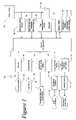
- FIG. 1is a block diagram of the vehicle information display and communication system of the present invention
- FIG. 2is a representation of a number of examples of visual outputs from the display module of the present invention.
- FIG. 3is a perspective view of one example of the display module and keypad of present invention.
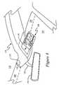
- FIG. 4is a perspective view of one example of an overhead console adapted to employ the antenna array and display module of the present invention.
- FIG. 5is a cross-sectional side view of the interface between the windshield and overhead console that houses the antenna array and display module of the present invention.
- the vehicle information and display system 10has a plurality of operative modules.
- the system 10also includes a control processing unit 12 that is adapted to provide an interface among the plurality of operative modules.
- the operative modulesinclude a display module 14 that is adapted to provide visual information to the occupants of the vehicle as shown by visual output block 16 .
- a navigation module 18is adapted for global positioning satellite reception to provide vehicle position information to the control processing unit 12 .
- a telecommunications module 20is adapted for wireless communication to provide an interface between the control processing unit 12 and a wireless telecommunications network (i.e.
- the telecommunication module 20also provides an interface between the control processing unit 12 and any one of a plurality of local wireless devices, such as PDAs, laptop computers, and cellular phones. This is accomplished by the addition of a short-range wireless RF transceiver module that operatively employs the Bluetooth standard telecommunication protocol.
- a local network interface module 24is also included that is adapted to provide communication between a vehicle control bus and the control processing unit 12 .
- the local network interface module 24is a local area network transceiver that operatively employs the CAN communication protocol.
- the local network interface module 24retrieves vehicle monitoring and health status information from the vehicle's local CAN data bus, as shown by the representative vehicle monitoring and health status block 26 .
- an antenna array 28which includes a GPS antenna is mounted in an overhead console and is in electrical communication with the navigation module 18 , the telecommunications module 20 , and any additional receiver modules that are represented herein by block 30 .
- the antenna array 28may also include the antenna used for Bluetooth interface with the short-range RF devices, shown as 32 in FIG. 1 . This is not strictly necessary since those devices enter into Bluetooth communication once inside the vehicle.
- the present inventionis not limited to incorporating only the types of systems named herein. As indicated at block 30 , the present invention may also include the integration of other types of receiver systems for use within the vehicle, such as satellite radio and television.
- an overhead consoleis adapted to extend forward over the upper edge of the vehicle windshield such that the GPS antenna maintains line-of-sight with at least one global positioning satellite transmitter at all times.
- the antenna array 28further includes a microwave antenna that operatively communicates with a cellular network using a standard cellular mobile communication format. It should be appreciated that due to the modular nature of the present invention, the system may be operatively made designed to include different stages of complexity and features. This would likely be a cost driven concern and may be left to the end user as to which modules to include in the system.
- the antenna array 28will also include an antenna that operatively receives a standardized communications format to provide satellite radio reception, and an antenna that operatively receives a standardized communications format to provide television reception.
- the preferred embodiment of the present inventionincludes the largest assortment of options and features which further includes a microphone system 34 adapted to receive voice signals or commands (shown as block 36 ) from the vehicle occupants, a speaker system 38 adapted to generate audio signals (shown as block 40 ) from the control processing unit 12 , and an audio conversion module 42 having a voice recognition circuit and a voice synthesizer circuit.
- the voice recognition circuitis adapted to receive voice commands 36 from the microphone system 34 , recognize particular predetermined voice commands as being one of a group of predetermined commands and to pass the recognized commands to the control processing unit 12 .
- the voice synthesizing circuitis adapted to process signals from said control processing unit 12 and synthesize the signals into intelligible audio (voice) output signals and to pass the voice output signals to the speaker system 38 .
- voice recognition and speech synthesisis not desired, or chosen as an installed option, the system 10 may be operated through the use of the keypad 44 .
- the use of the keypad 44allows command inputs (shown as block 46 ) to be entered into the system by causing the display module 14 to activate, which generates a series of menus and interactive display outputs 16 .
- the display module 14is mounted in the overhead console and further includes a vacuum fluorescent display unit as its visual output device.
- control processor unit 12further includes a memory module 48 .
- the memory module 48is adapted to provide the necessary memory storage space for the control processing unit 12 to operatively control the processes of the plurality of modules and to store a navigational database.
- the navigational databasemay be stored in the memory module 48 by downloading the navigation database from an outside source through a wireless telecommunication connection as supported by the telecommunication module 20 .
- the memory module 48further includes a fixed portion 50 and a removable portion 52 , the removable portion 52 is adapted to be interchangeable with like removable portions so as to allow the use of different removable memory portions (modules) having different stored navigational databases.
- the removable memory portion 52is further adapted to be interchangeable with like removable portions to allow a change in the size of the available memory.
- Display output 82indicates the general heading of the vehicle, the date and time, the local altitude, and the immediate weather conditions. The basic display may be altered to indicate latitude and longitude in addition to compass heading if desired.
- Display output 84is one of a variety of selectable displays that indicate instantaneous mileage, average mileage, distance to empty, and vehicle monitoring and health status indications.
- the vehicle monitoring and health status indicationsmay include a variety of particulars such as tire pressure, engine fluid states and temperatures and other system statuses.
- Display outputs 86 through 92indicate route and distance information from the vehicle's present position to gasoline, food, lodging, and medical facilities.
- Display output 94indicates points of interest in the environs of the chosen destination. It should be appreciated that it is required that a particular destination be programmed into the system 10 before this information display is available, and that the type of environ information that is displayed is also programmable and selectable. It should be further appreciated that these displays illustrated here are not exhaustive and any number of additional display outputs may be generated from the information available to the vehicle information display and communication system 10 .
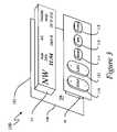
- a vehicle information display and communication system circuit boardis generally indicated at 100 in FIG. 3 .
- the display module 14 and keypad 44are mounted to the front face 104 of a printed circuit board 102 , so that the system 10 may be installed in an overhead console.
- the other modules of the system 10(not shown in FIG. 3 ) are mounted to the rear face 106 of the circuit board 102 so that they are supported on the circuit board and mounted within the overhead console with the display module 14 and keypad 44 .
- the keypad 44provides interaction with the system 10 by the individual keys as illustrated.
- the Step key 110steps through the various displays as provided by the List key 112 .
- the List key 112scrolls through option menus related to navigational database and the types and choices of information to be displayed.
- the List key 112 in combination with the Step key 110also provides the ability to enter a destination.
- the Reset key 114provides the ability to reset various stored and programmable information that is shown on the display module 14 by the use of the List and Step keys 112 and 110 .
- the E/M key 116toggles the display units between English and Metric units, and the Voice key 118 toggles voice recognition and speech synthesis on and off. It should be appreciated that the display module 14 and the keypad 44 need not be place together on the circuit board 102 and may be placed in other locations within the vehicle as long as the antenna array 28 is housed within the extended portion 136 of the overhead console 130 .
- an overhead console of the type employed for housing the antenna array 28 and the vehicle information display and communication system circuit board 100 of the present inventionis generally indicated at 130 .
- the overhead console 130is mounted to the vehicle's headliner 132 in a conventional manner.
- the headliner 132is further mounted to the interior side of the vehicle's roof 134 .
- the overhead console 130includes an extended portion 136 that continues forward beyond the headliner 132 out over a portion of the top the vehicle windshield 138 .
- the portion of the windshield 138 over which the extended portion 136 of the overhead console coversis indicated as 140 .
- the overhead console 130includes an open recess 142 in which the vehicle information display and communication system circuit board 100 is received and mounted.
- the overhead console 130has a skyway facing opening 144 that is connected to open recess 142 through the body of the overhead console.
- the skyward facing opening 144allows the mounting of the antenna array 28 , such that the antennas of the array are constantly presented with a skyward orientation.
- the overhead console 130 of the present inventionprovides the antenna array 28 with a full-time skyward exposure while housing the array within the vehicle interior and thereby avoiding any impact upon the shape, the aesthetics, or the styling of the vehicle.
- the placement of the antenna array 28 within the overhead console 130isolates the antennas from any metallic portions of the vehicle body 134 and its associated trim pieces as shown at 152 .
- the overhead console 130 of the present inventionmay also be adapted to provide a mounting for the arm 156 of the rearview mirror 158 .
- thisis also a vehicle design consideration and the rearview mirror arm 156 may be alternately mounted directly to the windshield 138 in the conventional manner.
- the included antennasmay take on any number of forms and easily fit within the overhead console 130 to achieve a maximum skyward exposure through the skyward facing opening 144 .
- an antennamay include two separate antenna portions that are formed as quarter wave strips resembling inverted triangles or wedges to function as a broadband antenna. Such a construction may also necessitate a localized metallic coating within a portion of the skyward facing opening 144 to serve as the ground plane for this antenna.
- the included GPS antennamay be of a simple patch construction formed of an electrically conductive material placed on substrate. Dual band cellular antennas may be also configured as having a similar broadband structure including two wedge-shaped strips.
- the size of the antenna array 28may be extended across the width of the upper portion of the windshield as indicated at 160 in FIG. 4 .
- This area 160may be left transparent, or may by covered by a further extension of the headliner 132 , or by a widening of the extension 136 of the overhead console 130 .
- almost any manner of antenna constructionmay be incorporated in the present invention and easily fit within the extended portion 136 of the overhead console 130 and that the choices of the type and style of antenna used in the antenna array 28 is a design consideration for the vehicle manufacture and does not limit the scope and intent of the present invention described herein.
- the overhead console 130 of the present inventionprovides the antenna array 28 with a full-time skyward exposure while housing the array within the vehicle interior and thereby avoiding any impact upon the shape, the aesthetics, or the styling of the vehicle. Further, the placement of the antenna array 28 within the overhead console 130 isolates the antennas from any metallic portions of the vehicle body 134 and its associated trim pieces as shown.
- the present inventionprovides a vehicle information display and communication system that maintains constant contact with the GPS navigational reference, microwave communication, and all other forms of interactive communication that are installed in the vehicle. Further, the placement of the antenna array is such that it is unobtrusive, generally hidden, and does not extend into the outer surface of the vehicle, thereby preserving the vehicle's styling and aesthetics.
Landscapes
- Engineering & Computer Science (AREA)
- Radar, Positioning & Navigation (AREA)
- Remote Sensing (AREA)
- Automation & Control Theory (AREA)
- Physics & Mathematics (AREA)
- General Physics & Mathematics (AREA)
- Fittings On The Vehicle Exterior For Carrying Loads, And Devices For Holding Or Mounting Articles (AREA)
Abstract
Description
Claims (17)
Priority Applications (3)
| Application Number | Priority Date | Filing Date | Title |
|---|---|---|---|
| US10/749,895US7049982B2 (en) | 2003-12-31 | 2003-12-31 | Vehicle information display and communication system having an antenna array |
| DE102004056268ADE102004056268A1 (en) | 2003-12-31 | 2004-11-22 | Information display and communication system of a vehicle having an antenna arrangement |
| GB0426016AGB2409934A (en) | 2003-12-31 | 2004-11-26 | Vehicle communication system with windscreen antenna array |
Applications Claiming Priority (1)
| Application Number | Priority Date | Filing Date | Title |
|---|---|---|---|
| US10/749,895US7049982B2 (en) | 2003-12-31 | 2003-12-31 | Vehicle information display and communication system having an antenna array |
Publications (2)
| Publication Number | Publication Date |
|---|---|
| US20050146445A1 US20050146445A1 (en) | 2005-07-07 |
| US7049982B2true US7049982B2 (en) | 2006-05-23 |
Family
ID=33565414
Family Applications (1)
| Application Number | Title | Priority Date | Filing Date |
|---|---|---|---|
| US10/749,895Expired - Fee RelatedUS7049982B2 (en) | 2003-12-31 | 2003-12-31 | Vehicle information display and communication system having an antenna array |
Country Status (3)
| Country | Link |
|---|---|
| US (1) | US7049982B2 (en) |
| DE (1) | DE102004056268A1 (en) |
| GB (1) | GB2409934A (en) |
Cited By (17)
| Publication number | Priority date | Publication date | Assignee | Title |
|---|---|---|---|---|
| US20080027643A1 (en)* | 2006-07-28 | 2008-01-31 | Basir Otman A | Vehicle communication system with navigation |
| US20100305807A1 (en)* | 2009-05-28 | 2010-12-02 | Basir Otman A | Communication system with personal information management and remote vehicle monitoring and control features |
| US7970446B2 (en) | 1999-05-26 | 2011-06-28 | Johnson Controls Technology Company | Wireless control system and method |
| US7986914B1 (en)* | 2007-06-01 | 2011-07-26 | At&T Mobility Ii Llc | Vehicle-based message control using cellular IP |
| US20120116670A1 (en)* | 2010-11-09 | 2012-05-10 | Darin Paul Rosekrans | Range marker for a navigation system |
| US20120158210A1 (en)* | 2010-12-20 | 2012-06-21 | Continental Automotive Gmbh | Onboard Information System With Antenna For Receiving Satellite-Based Geoposition Data |
| US8380251B2 (en) | 1999-05-26 | 2013-02-19 | Johnson Controls Technology Company | Wireless communications system and method |
| US8655586B2 (en) | 2011-12-28 | 2014-02-18 | Toyota Motor Engineering & Manufacturing North America, Inc. | Intelligent range map for an electric vehicle |
| US8770644B2 (en) | 2010-09-25 | 2014-07-08 | Volkswagen Ag | Vehicle having an overhead console |
| US8838075B2 (en) | 2008-06-19 | 2014-09-16 | Intelligent Mechatronic Systems Inc. | Communication system with voice mail access and call by spelling functionality |
| US8856009B2 (en) | 2008-03-25 | 2014-10-07 | Intelligent Mechatronic Systems Inc. | Multi-participant, mixed-initiative voice interaction system |
| US9652023B2 (en) | 2008-07-24 | 2017-05-16 | Intelligent Mechatronic Systems Inc. | Power management system |
| US9667726B2 (en) | 2009-06-27 | 2017-05-30 | Ridetones, Inc. | Vehicle internet radio interface |
| US9930158B2 (en) | 2005-06-13 | 2018-03-27 | Ridetones, Inc. | Vehicle immersive communication system |
| US9978272B2 (en) | 2009-11-25 | 2018-05-22 | Ridetones, Inc | Vehicle to vehicle chatting and communication system |
| US20190029128A1 (en)* | 2017-07-21 | 2019-01-24 | Ford Global Technologies, Llc | Housing to clad electrical components of a motor vehicle |
| US10600421B2 (en) | 2014-05-23 | 2020-03-24 | Samsung Electronics Co., Ltd. | Mobile terminal and control method thereof |
Families Citing this family (32)
| Publication number | Priority date | Publication date | Assignee | Title |
|---|---|---|---|---|
| US7391321B2 (en)* | 2005-01-10 | 2008-06-24 | Terahop Networks, Inc. | Keyhole communication device for tracking and monitoring shipping container and contents thereof |
| US7940716B2 (en) | 2005-07-01 | 2011-05-10 | Terahop Networks, Inc. | Maintaining information facilitating deterministic network routing |
| US7574300B2 (en) | 2005-06-16 | 2009-08-11 | Terahop Networks, Inc. | GPS denial device detection and location system |
| US7574168B2 (en) | 2005-06-16 | 2009-08-11 | Terahop Networks, Inc. | Selective GPS denial system |
| US7430437B2 (en) | 2000-12-22 | 2008-09-30 | Terahop Networks, Inc. | Transmitting sensor-acquired data using step-power filtering |
| US7394361B1 (en)* | 2005-01-10 | 2008-07-01 | Terahop Networks, Inc. | Keyhole communication device for tracking and monitoring shipping container and contents thereof |
| US7733818B2 (en)* | 2000-12-22 | 2010-06-08 | Terahop Networks, Inc. | Intelligent node communication using network formation messages in a mobile Ad hoc network |
| US7783246B2 (en) | 2005-06-16 | 2010-08-24 | Terahop Networks, Inc. | Tactical GPS denial and denial detection system |
| US20080303897A1 (en) | 2000-12-22 | 2008-12-11 | Terahop Networks, Inc. | Visually capturing and monitoring contents and events of cargo container |
| US7522568B2 (en) | 2000-12-22 | 2009-04-21 | Terahop Networks, Inc. | Propagating ad hoc wireless networks based on common designation and routine |
| US8050625B2 (en) | 2000-12-22 | 2011-11-01 | Terahop Networks, Inc. | Wireless reader tags (WRTs) with sensor components in asset monitoring and tracking systems |
| US7583769B2 (en) | 2005-06-16 | 2009-09-01 | Terahop Netowrks, Inc. | Operating GPS receivers in GPS-adverse environment |
| US7142107B2 (en) | 2004-05-27 | 2006-11-28 | Lawrence Kates | Wireless sensor unit |
| JP4771403B2 (en)* | 2004-09-29 | 2011-09-14 | 本田技研工業株式会社 | GPS built-in meter |
| DE102005015750B4 (en)* | 2005-04-06 | 2008-08-14 | Audi Ag | Modular self-configuring headliner sub-group |
| US7352333B2 (en)* | 2005-09-29 | 2008-04-01 | Freescale Semiconductor, Inc. | Frequency-notching antenna |
| WO2007067831A1 (en) | 2005-10-31 | 2007-06-14 | Terahop Networks, Inc. | Determining relative elevation using gps and ranging |
| EP1972159A1 (en)* | 2006-01-01 | 2008-09-24 | Terahop Networks, Inc. | Determining presence of radio frequency communication device |
| US20090129306A1 (en) | 2007-02-21 | 2009-05-21 | Terahop Networks, Inc. | Wake-up broadcast including network information in common designation ad hoc wireless networking |
| US8880133B2 (en)* | 2006-12-01 | 2014-11-04 | Intelligent Mechatronic Systems Inc. | Vehicle communication device |
| US7903724B2 (en)* | 2007-01-31 | 2011-03-08 | Broadcom Corporation | RF transceiver device with RF bus |
| US8223680B2 (en) | 2007-02-21 | 2012-07-17 | Google Inc. | Mesh network control using common designation wake-up |
| US8462662B2 (en) | 2008-05-16 | 2013-06-11 | Google Inc. | Updating node presence based on communication pathway |
| WO2009151877A2 (en) | 2008-05-16 | 2009-12-17 | Terahop Networks, Inc. | Systems and apparatus for securing a container |
| US8391435B2 (en) | 2008-12-25 | 2013-03-05 | Google Inc. | Receiver state estimation in a duty cycled radio |
| US8300551B2 (en) | 2009-01-28 | 2012-10-30 | Google Inc. | Ascertaining presence in wireless networks |
| US8705523B2 (en) | 2009-02-05 | 2014-04-22 | Google Inc. | Conjoined class-based networking |
| US9049564B2 (en)* | 2013-02-04 | 2015-06-02 | Zf Friedrichshafen Ag | Vehicle broadcasting system |
| US9112790B2 (en) | 2013-06-25 | 2015-08-18 | Google Inc. | Fabric network |
| DE102014213026A1 (en)* | 2014-07-04 | 2016-01-07 | Bayerische Motoren Werke Aktiengesellschaft | Short-range radio communication on a vehicle |
| US10482877B2 (en)* | 2015-08-28 | 2019-11-19 | Hewlett-Packard Development Company, L.P. | Remote sensor voice recognition |
| CN110557158A (en)* | 2018-05-30 | 2019-12-10 | 上海擎感智能科技有限公司 | Vehicle-mounted terminal |
Citations (17)
| Publication number | Priority date | Publication date | Assignee | Title |
|---|---|---|---|---|
| US4867498A (en) | 1988-12-02 | 1989-09-19 | Chivas Products Limited | Overhead console assembly |
| US5323321A (en) | 1990-06-25 | 1994-06-21 | Motorola, Inc. | Land vehicle navigation apparatus |
| EP0675341A1 (en) | 1994-03-29 | 1995-10-04 | Honda Giken Kogyo Kabushiki Kaisha | Car navigation system |
| US5555172A (en) | 1994-08-22 | 1996-09-10 | Prince Corporation | User interface for controlling accessories and entering data in a vehicle |
| US6125030A (en) | 1998-08-07 | 2000-09-26 | Lear Donnelly Overhead Systems L.L.C. | Vehicle overhead console with flip down navigation unit |
| US6257745B1 (en) | 1999-12-14 | 2001-07-10 | Daimlerchrysler Corporation | Flexible arm light for automobile overhead console |
| US20020032510A1 (en) | 2000-04-06 | 2002-03-14 | Turnbull Robert R. | Vehicle rearview mirror assembly incorporating a communication system |
| WO2002035646A1 (en) | 2000-10-26 | 2002-05-02 | Advanced Automotive Antennas, S.L. | Integrated multiservice car antenna |
| US6420975B1 (en)* | 1999-08-25 | 2002-07-16 | Donnelly Corporation | Interior rearview mirror sound processing system |
| US20030025793A1 (en) | 2001-07-31 | 2003-02-06 | Mcmahon Martha A. | Video processor module for use in a vehicular video system |
| US6539306B2 (en)* | 2001-06-15 | 2003-03-25 | Gentex Corporation | Automotive mirror with integrated Loran components |
| US20030075955A1 (en) | 2001-10-19 | 2003-04-24 | Tiesler John M. | Modular overhead console assembly |
| US20030169522A1 (en) | 2002-01-31 | 2003-09-11 | Kenneth Schofield | Vehicle accessory module |
| JP2003269990A (en) | 2002-03-15 | 2003-09-25 | Nec Access Technica Ltd | Cellular telephone system with gps function, charging method for the system, and movable body position detecting method |
| JP2003273625A (en) | 2002-03-18 | 2003-09-26 | Central Glass Co Ltd | Vehicle glass antenna |
| US6678614B2 (en)* | 1999-11-24 | 2004-01-13 | Donnelly Corporation | Navigation system for a vehicle |
| US20040032675A1 (en)* | 2002-06-06 | 2004-02-19 | Weller Andrew D. | Interior rearview mirror system with compass |
- 2003
- 2003-12-31USUS10/749,895patent/US7049982B2/ennot_activeExpired - Fee Related
- 2004
- 2004-11-22DEDE102004056268Apatent/DE102004056268A1/ennot_activeCeased
- 2004-11-26GBGB0426016Apatent/GB2409934A/ennot_activeWithdrawn
Patent Citations (17)
| Publication number | Priority date | Publication date | Assignee | Title |
|---|---|---|---|---|
| US4867498A (en) | 1988-12-02 | 1989-09-19 | Chivas Products Limited | Overhead console assembly |
| US5323321A (en) | 1990-06-25 | 1994-06-21 | Motorola, Inc. | Land vehicle navigation apparatus |
| EP0675341A1 (en) | 1994-03-29 | 1995-10-04 | Honda Giken Kogyo Kabushiki Kaisha | Car navigation system |
| US5555172A (en) | 1994-08-22 | 1996-09-10 | Prince Corporation | User interface for controlling accessories and entering data in a vehicle |
| US6125030A (en) | 1998-08-07 | 2000-09-26 | Lear Donnelly Overhead Systems L.L.C. | Vehicle overhead console with flip down navigation unit |
| US6420975B1 (en)* | 1999-08-25 | 2002-07-16 | Donnelly Corporation | Interior rearview mirror sound processing system |
| US6678614B2 (en)* | 1999-11-24 | 2004-01-13 | Donnelly Corporation | Navigation system for a vehicle |
| US6257745B1 (en) | 1999-12-14 | 2001-07-10 | Daimlerchrysler Corporation | Flexible arm light for automobile overhead console |
| US20020032510A1 (en) | 2000-04-06 | 2002-03-14 | Turnbull Robert R. | Vehicle rearview mirror assembly incorporating a communication system |
| WO2002035646A1 (en) | 2000-10-26 | 2002-05-02 | Advanced Automotive Antennas, S.L. | Integrated multiservice car antenna |
| US6539306B2 (en)* | 2001-06-15 | 2003-03-25 | Gentex Corporation | Automotive mirror with integrated Loran components |
| US20030025793A1 (en) | 2001-07-31 | 2003-02-06 | Mcmahon Martha A. | Video processor module for use in a vehicular video system |
| US20030075955A1 (en) | 2001-10-19 | 2003-04-24 | Tiesler John M. | Modular overhead console assembly |
| US20030169522A1 (en) | 2002-01-31 | 2003-09-11 | Kenneth Schofield | Vehicle accessory module |
| JP2003269990A (en) | 2002-03-15 | 2003-09-25 | Nec Access Technica Ltd | Cellular telephone system with gps function, charging method for the system, and movable body position detecting method |
| JP2003273625A (en) | 2002-03-18 | 2003-09-26 | Central Glass Co Ltd | Vehicle glass antenna |
| US20040032675A1 (en)* | 2002-06-06 | 2004-02-19 | Weller Andrew D. | Interior rearview mirror system with compass |
Cited By (31)
| Publication number | Priority date | Publication date | Assignee | Title |
|---|---|---|---|---|
| US8634888B2 (en) | 1999-05-26 | 2014-01-21 | Johnson Controls Technology Company | Wireless control system and method |
| US7970446B2 (en) | 1999-05-26 | 2011-06-28 | Johnson Controls Technology Company | Wireless control system and method |
| US9370041B2 (en) | 1999-05-26 | 2016-06-14 | Visteon Global Technologies, Inc. | Wireless communications system and method |
| US8380251B2 (en) | 1999-05-26 | 2013-02-19 | Johnson Controls Technology Company | Wireless communications system and method |
| US9318017B2 (en) | 1999-05-26 | 2016-04-19 | Visteon Global Technologies, Inc. | Wireless control system and method |
| US8494449B2 (en) | 1999-05-26 | 2013-07-23 | Johnson Controls Technology Company | Wireless communications system and method |
| US8897708B2 (en) | 1999-05-26 | 2014-11-25 | Johnson Controls Technology Company | Wireless communications system and method |
| US9930158B2 (en) | 2005-06-13 | 2018-03-27 | Ridetones, Inc. | Vehicle immersive communication system |
| US9976865B2 (en)* | 2006-07-28 | 2018-05-22 | Ridetones, Inc. | Vehicle communication system with navigation |
| US20080027643A1 (en)* | 2006-07-28 | 2008-01-31 | Basir Otman A | Vehicle communication system with navigation |
| US9478215B2 (en) | 2007-06-01 | 2016-10-25 | At&T Mobility Ii Llc | Vehicle-based message control using cellular IP |
| US8467721B2 (en) | 2007-06-01 | 2013-06-18 | At&T Mobility Ii Llc | Systems and methods for delivering a converted message to a vehicle media system |
| US7986914B1 (en)* | 2007-06-01 | 2011-07-26 | At&T Mobility Ii Llc | Vehicle-based message control using cellular IP |
| US8856009B2 (en) | 2008-03-25 | 2014-10-07 | Intelligent Mechatronic Systems Inc. | Multi-participant, mixed-initiative voice interaction system |
| US8838075B2 (en) | 2008-06-19 | 2014-09-16 | Intelligent Mechatronic Systems Inc. | Communication system with voice mail access and call by spelling functionality |
| US9652023B2 (en) | 2008-07-24 | 2017-05-16 | Intelligent Mechatronic Systems Inc. | Power management system |
| US8577543B2 (en) | 2009-05-28 | 2013-11-05 | Intelligent Mechatronic Systems Inc. | Communication system with personal information management and remote vehicle monitoring and control features |
| US20100305807A1 (en)* | 2009-05-28 | 2010-12-02 | Basir Otman A | Communication system with personal information management and remote vehicle monitoring and control features |
| US9667726B2 (en) | 2009-06-27 | 2017-05-30 | Ridetones, Inc. | Vehicle internet radio interface |
| US9978272B2 (en) | 2009-11-25 | 2018-05-22 | Ridetones, Inc | Vehicle to vehicle chatting and communication system |
| US8770644B2 (en) | 2010-09-25 | 2014-07-08 | Volkswagen Ag | Vehicle having an overhead console |
| US9043134B2 (en)* | 2010-11-09 | 2015-05-26 | Toyota Motor Engineering & Manufacturing North America, Inc. | Range marker for a navigation system |
| US20120116670A1 (en)* | 2010-11-09 | 2012-05-10 | Darin Paul Rosekrans | Range marker for a navigation system |
| US9677902B2 (en)* | 2010-11-09 | 2017-06-13 | Toyota Motor Engineering & Manufacturing North America, Inc. | Range marker for a navigation system |
| US20160131498A1 (en)* | 2010-11-09 | 2016-05-12 | Toyota Motor Engineering & Manufacturing North America, Inc. | Range marker for a navigation system |
| US20120158210A1 (en)* | 2010-12-20 | 2012-06-21 | Continental Automotive Gmbh | Onboard Information System With Antenna For Receiving Satellite-Based Geoposition Data |
| US9087416B2 (en)* | 2010-12-20 | 2015-07-21 | Continental Automotive Gmbh | Onboard information system with antenna for receiving satellite-based geoposition data |
| US8655586B2 (en) | 2011-12-28 | 2014-02-18 | Toyota Motor Engineering & Manufacturing North America, Inc. | Intelligent range map for an electric vehicle |
| US10600421B2 (en) | 2014-05-23 | 2020-03-24 | Samsung Electronics Co., Ltd. | Mobile terminal and control method thereof |
| US20190029128A1 (en)* | 2017-07-21 | 2019-01-24 | Ford Global Technologies, Llc | Housing to clad electrical components of a motor vehicle |
| US10512177B2 (en)* | 2017-07-21 | 2019-12-17 | Ford Global Technologies, Llc | Housing to clad electrical components of a motor vehicle |
Also Published As
| Publication number | Publication date |
|---|---|
| GB0426016D0 (en) | 2004-12-29 |
| DE102004056268A1 (en) | 2005-08-04 |
| GB2409934A (en) | 2005-07-13 |
| US20050146445A1 (en) | 2005-07-07 |
Similar Documents
| Publication | Publication Date | Title |
|---|---|---|
| US7049982B2 (en) | Vehicle information display and communication system having an antenna array | |
| US7023379B2 (en) | Vehicle rearview assembly incorporating a tri-band antenna module | |
| CA2400752C (en) | Vehicle rearview mirror assembly incorporating a communication system | |
| EP1638810B1 (en) | Rearview mirror assemblies incorporating hands-free telephone components | |
| US6701161B1 (en) | Multimedia unit | |
| EP1078818B1 (en) | Interior rearview mirror sound processing system | |
| EP2340966B1 (en) | Rear view mirror for a vehicle with an antenna module and an electronic display module | |
| CA2356193A1 (en) | Rearview mirror with integrated microwave receiver | |
| JP2004128940A (en) | Vehicle composite antenna device and communication system using the same | |
| JP2006279344A (en) | Integrated antenna system | |
| JPH0658608U (en) | Resin window antenna structure |
Legal Events
| Date | Code | Title | Description |
|---|---|---|---|
| AS | Assignment | Owner name:LEAR CORPORATION, MICHIGAN Free format text:ASSIGNMENT OF ASSIGNORS INTEREST;ASSIGNORS:SLEBODA, PAWEL W.;LEMENSE, THOMAS J.;REEL/FRAME:014764/0485 Effective date:20040108 | |
| AS | Assignment | Owner name:JPMORGAN CHASE BANK, N.A., AS GENERAL ADMINISTRATI Free format text:SECURITY AGREEMENT;ASSIGNOR:LEAR CORPORATION;REEL/FRAME:017858/0719 Effective date:20060425 | |
| REMI | Maintenance fee reminder mailed | ||
| LAPS | Lapse for failure to pay maintenance fees | ||
| STCH | Information on status: patent discontinuation | Free format text:PATENT EXPIRED DUE TO NONPAYMENT OF MAINTENANCE FEES UNDER 37 CFR 1.362 | |
| FP | Lapsed due to failure to pay maintenance fee | Effective date:20100523 | |
| AS | Assignment | Owner name:LEAR CORPORATION, MICHIGAN Free format text:RELEASE BY SECURED PARTY;ASSIGNOR:JPMORGAN CHASE BANK, N.A.;REEL/FRAME:032722/0553 Effective date:20100830 | |
| AS | Assignment | Owner name:LEAR CORPORATION, MICHIGAN Free format text:RELEASE BY SECURED PARTY;ASSIGNOR:JPMORGAN CHASE BANK, N.A., AS AGENT;REEL/FRAME:037731/0918 Effective date:20160104 |