US7049961B2 - Key control system using separated ID and location detection mechanisms - Google Patents
Key control system using separated ID and location detection mechanismsDownload PDFInfo
- Publication number
- US7049961B2 US7049961B2US10/924,330US92433004AUS7049961B2US 7049961 B2US7049961 B2US 7049961B2US 92433004 AUS92433004 AUS 92433004AUS 7049961 B2US7049961 B2US 7049961B2
- Authority
- US
- United States
- Prior art keywords
- scan
- key
- receptacle
- slot
- storage unit
- Prior art date
- Legal status (The legal status is an assumption and is not a legal conclusion. Google has not performed a legal analysis and makes no representation as to the accuracy of the status listed.)
- Expired - Lifetime
Links
Images


Classifications
- G—PHYSICS
- G08—SIGNALLING
- G08B—SIGNALLING OR CALLING SYSTEMS; ORDER TELEGRAPHS; ALARM SYSTEMS
- G08B13/00—Burglar, theft or intruder alarms
- G08B13/22—Electrical actuation
- G08B13/24—Electrical actuation by interference with electromagnetic field distribution
- G08B13/2402—Electronic Article Surveillance [EAS], i.e. systems using tags for detecting removal of a tagged item from a secure area, e.g. tags for detecting shoplifting
- G08B13/2405—Electronic Article Surveillance [EAS], i.e. systems using tags for detecting removal of a tagged item from a secure area, e.g. tags for detecting shoplifting characterised by the tag technology used
- G08B13/2414—Electronic Article Surveillance [EAS], i.e. systems using tags for detecting removal of a tagged item from a secure area, e.g. tags for detecting shoplifting characterised by the tag technology used using inductive tags
- G08B13/2417—Electronic Article Surveillance [EAS], i.e. systems using tags for detecting removal of a tagged item from a secure area, e.g. tags for detecting shoplifting characterised by the tag technology used using inductive tags having a radio frequency identification chip
- A—HUMAN NECESSITIES
- A47—FURNITURE; DOMESTIC ARTICLES OR APPLIANCES; COFFEE MILLS; SPICE MILLS; SUCTION CLEANERS IN GENERAL
- A47G—HOUSEHOLD OR TABLE EQUIPMENT
- A47G29/00—Supports, holders, or containers for household use, not provided for in groups A47G1/00-A47G27/00 or A47G33/00
- A47G29/10—Key holders; Key boards
- G—PHYSICS
- G06—COMPUTING OR CALCULATING; COUNTING
- G06K—GRAPHICAL DATA READING; PRESENTATION OF DATA; RECORD CARRIERS; HANDLING RECORD CARRIERS
- G06K17/00—Methods or arrangements for effecting co-operative working between equipments covered by two or more of main groups G06K1/00 - G06K15/00, e.g. automatic card files incorporating conveying and reading operations
- G—PHYSICS
- G06—COMPUTING OR CALCULATING; COUNTING
- G06K—GRAPHICAL DATA READING; PRESENTATION OF DATA; RECORD CARRIERS; HANDLING RECORD CARRIERS
- G06K7/00—Methods or arrangements for sensing record carriers, e.g. for reading patterns
- G06K7/10—Methods or arrangements for sensing record carriers, e.g. for reading patterns by electromagnetic radiation, e.g. optical sensing; by corpuscular radiation
- G06K7/10009—Methods or arrangements for sensing record carriers, e.g. for reading patterns by electromagnetic radiation, e.g. optical sensing; by corpuscular radiation sensing by radiation using wavelengths larger than 0.1 mm, e.g. radio-waves or microwaves
- G06K7/10019—Methods or arrangements for sensing record carriers, e.g. for reading patterns by electromagnetic radiation, e.g. optical sensing; by corpuscular radiation sensing by radiation using wavelengths larger than 0.1 mm, e.g. radio-waves or microwaves resolving collision on the communication channels between simultaneously or concurrently interrogated record carriers.
- G06K7/10079—Methods or arrangements for sensing record carriers, e.g. for reading patterns by electromagnetic radiation, e.g. optical sensing; by corpuscular radiation sensing by radiation using wavelengths larger than 0.1 mm, e.g. radio-waves or microwaves resolving collision on the communication channels between simultaneously or concurrently interrogated record carriers. the collision being resolved in the spatial domain, e.g. temporary shields for blindfolding the interrogator in specific directions
- G—PHYSICS
- G08—SIGNALLING
- G08B—SIGNALLING OR CALLING SYSTEMS; ORDER TELEGRAPHS; ALARM SYSTEMS
- G08B13/00—Burglar, theft or intruder alarms
- G08B13/22—Electrical actuation
- G08B13/24—Electrical actuation by interference with electromagnetic field distribution
- G08B13/2402—Electronic Article Surveillance [EAS], i.e. systems using tags for detecting removal of a tagged item from a secure area, e.g. tags for detecting shoplifting
- G08B13/2451—Specific applications combined with EAS
- G08B13/2462—Asset location systems combined with EAS
- G—PHYSICS
- G07—CHECKING-DEVICES
- G07C—TIME OR ATTENDANCE REGISTERS; REGISTERING OR INDICATING THE WORKING OF MACHINES; GENERATING RANDOM NUMBERS; VOTING OR LOTTERY APPARATUS; ARRANGEMENTS, SYSTEMS OR APPARATUS FOR CHECKING NOT PROVIDED FOR ELSEWHERE
- G07C9/00—Individual registration on entry or exit
- G07C9/00174—Electronically operated locks; Circuits therefor; Nonmechanical keys therefor, e.g. passive or active electrical keys or other data carriers without mechanical keys
- G07C9/00896—Electronically operated locks; Circuits therefor; Nonmechanical keys therefor, e.g. passive or active electrical keys or other data carriers without mechanical keys specially adapted for particular uses
- G07C2009/00936—Electronically operated locks; Circuits therefor; Nonmechanical keys therefor, e.g. passive or active electrical keys or other data carriers without mechanical keys specially adapted for particular uses for key cabinets
Definitions
- the present inventionis generally related to controlling and tracking access to various types of objects. More particularly, the present invention relates to an object control system for continuous inventory of a plurality of objects.
- each tagincludes an addressable switch, and an LED on the tag lights when the ID code of the particular tag within the receptacle is transmitted by the controller.
- the controllercan never identify the specific location of a tag within the receptacle.
- the inventor's previous object tracking patentsU.S. Pat. Nos. 5,801,628 and 6,075,441, used one-wire memory buttons on key tags as a preferred embodiment.
- the presence of a key tag in a key tag slotwas determined by selectively polling each slot location using a matrix selector.
- the one-wire memory buttonshave unique identification (ID) codes that allow the key control system to identify which key tag is inserted in each slot.
- IDunique identification
- the inventor's prior RF key control system patent, U.S. Pat. No. 6,204,764used radio frequency identification (RFID) tags on key tags. At each tag slot, an RFID sensor antenna was placed to communicate, and again, a matrix selector approach was used to poll each slot. Because the RFID tags contain unique ID codes, this system also determines presence and identification in the same process.
- RFIDradio frequency identification
- the present inventionseparates the object identification function and the object location detection function in a key control system. More generally, the present invention provides an object control and tracking system and related methods that use separate object identification and location detection mechanisms for objects, that are maintained in a secure enclosure.
- a plurality of object slots that are “electrically small” in comparison to the wavelength of the RFID sensorsare located on the top tray of the enclosure to receive object tags that include both an RFID tag and an object to be tracked.
- the objectsare attached to a portion of the object tags that are outside of the enclosure.
- Presence detectors positioned on the backplane of the enclosureare used to determine if an object tag is present in the corresponding slot of the enclosure.
- RFID sensors located on opposite interior side walls of the enclosureinterrogate each RFID tag to determine the presence of each RFID tag within the enclosure.
- Each RFID tagincludes an anti-collision protocol to enable a plurality of RFID tags within the sensor field to be interrogated.
- the RFID sensorsinclude a pair of sensor coils and the RFID tags are inductive. The pair of sensor coils generate a magnetic field between the side walls of the enclosure, the magnetic field being normal to the vertical surface of each object tag.
- the RFID sensorsinclude capacitive plates, and the RFID tags are capacitive.
- the object control enclosureis constructed of metal and is shielded to prevent detection of object tags that are located externally to the enclosure and that could be contained in a separate object control enclosure.
- the object control and tracking systemincludes a processor, a memory for storing an object control database, and related processing logic operating on the processor to control scanning of the presence detectors to determine if an object tag is present in a corresponding slot, to identify each object (via its unique RFID tag) present in the enclosure and to compare the identified objects with an object control database to determine each object removed or replaced since the previous database update.
- switches mounted on the backplaneare suitable for use as object tag presence detectors. These include a contact switch having a lever that is engaged to close the contact switch when an object tag is inserted into a corresponding slot.
- Another suitable switchincludes a photo-conducting switch mounted to the backplane on a side of a corresponding slot with a light emitting diode mounted on the opposite side, such that insertion of the object tag into the slot causes an electrical circuit to open to indicate the presence of an object tag.
- the object tagcan also include a metallic end portion or an embedded magnetic material that causes an electrical circuit to close when either an object tag is inserted into the corresponding slot and is detected by engaging a pair of contacts in the slot or when a reed switch is energized by proximity of the object tag.
- each object tagincludes a light emitting diode circuit, an RFID addressable switch and an RFID tag coil.
- An RFID addressable switchenables an RFID interrogating field to selectively activate a light emitting diode on the object tag corresponding to the object a user is trying to identify in order to remove the object from the enclosure.
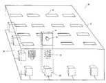
- FIG. 1illustrates an exemplary embodiment of a key control assembly in which the identification and location detection system mechanisms are separated.
- FIG. 2illustrates the processing logic for accessing a key drawer in accordance with an exemplary embodiment of the present invention.
- FIG. 3illustrates the processing logic associated with the closing of a key control drawer in accordance with an exemplary embodiment of the present invention.
- FIGS. 4A–4Billustrate the location of the RFID sensor coils within the key control system in accordance with an exemplary embodiment of the present invention.
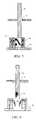
- FIG. 5illustrates the use of an electrical switch to detect the use of key tags in key tag slots in accordance with an exemplary embodiment of the present invention.
- FIG. 6illustrates an alternate embodiment of the use of an electrical switch to detect the presence of key tags in key tag slots.
- FIG. 7illustrates the use of a photo-conducting switch to detect the presence of key tags in key tag slots in accordance with an exemplary embodiment of the present invention.
- FIG. 8illustrates the use of a magnetic reed switch to detect the presence of key tags in key tag slots in accordance with an exemplary embodiment of the present invention.
- FIG. 9illustrates the concept of encoding switches into a matrix in accordance with an exemplary embodiment of the present invention.
- FIGS. 10A–10Billustrate in a perspective and an end view, the use of key tag receptacles on the backplane below each key tag for key tag alignment in accordance with an exemplary embodiment of the present invention.
- FIGS. 11A–11Billustrate the attachment of key tag alignment devices to the bottom or top of the top tray of the key drawer respectively, in accordance with an exemplary embodiment of the present invention.
- FIG. 12illustrates the inclusion of a LED with an inductive RFID tag in accordance with an exemplary embodiment of the present invention.
- FIG. 13illustrates a capacitive RFID tag in accordance with an exemplary embodiment of the present invention.
- FIG. 1A representation of a key control assembly having separated identification and location detection functions is illustrated in FIG. 1 .
- the key control assembly 10is a portion of a key control system.
- the key control assembly 10includes a key control enclosure 12 .
- the key tags 14are inserted through narrow key-tag slots 16 in the top tray 15 of the enclosure 12 .
- the portion of the key tag 14 that is inside the enclosurecontains an RFID tag 18 .
- the keysare attached, via key attachment 20 , to the portion of the key tags that are outside the key control enclosure 12 .
- Presence detectors 22are placed on a backplane 24 on the bottom of the enclosure 12 .
- Corresponding to each presence detector 22is a row selection line 23 and a column selection line 25 .
- the presence detectors 22are connected in a configuration similar to that found in a keyboard switch matrix. Each presence detector 22 has its own associated row selection line and column selection line.
- FIG. 9shows a simplified circuit of a 2 ⁇ 2 switch matrix. The presence or absence of a key tag at each slot is thus determined.
- Global RFID sensor coilsare placed inside the enclosure near the right and left walls.
- the locations of RFID sensor coil A and RFID sensor coil Bare indicated by reference numerals 27 , 29 in FIG. 1 .
- This pair of coilsis used to interrogate and identify any RFID tags 18 that are present inside the enclosure 12 .
- Alternative embodiments using a single coil or multiple sets of coilsare also possible.
- the key control systemknows which slots 16 are occupied from the presence detectors 22 , and knows which key tags 14 are inserted into the system from the RFID sensors. For some applications this may be sufficient. However, other applications require knowledge of which key tag 14 is inserted into which slot 16 . This knowledge can be determined during operation as described in the flow chart illustrated in FIG. 2 .
- the key control systemincludes a controller (e.g., microcontroller, personal computer), a memory device, a display and other components.
- the procedure illustrated in FIG. 2is executed by the programmed controller when the key drawer is being accessed. Scanning the matrix of presence detectors 22 starts the process as indicated in logic block 200 . This is a very rapid process because each presence detector 22 is functionally just a switch that is either opened or closed. Most likely, the scanning of the presence detectors 22 is so fast that only a single key tag 14 will be removed or replaced before the key control system has a chance to respond. The result of the scan is compared with the known drawer status as indicated in logic block 210 .
- a testis made to determine if the state has changed. If the state has changed, then the user is prompted to wait while the key tag scan is in progress, as indicated by logic block 230 .
- the key tag scanmay take up to a few seconds to complete. While the key tag scan is in progress, the monitoring of the presence detectors 22 continues. If any additional key tag changes are detected, the key tag scan will be restarted.
- the key tag scanis performed using the RFID tag sensor.
- RFID tagshave anti-collision protocols that allow multiple tags within a sensor field to be interrogated.
- the RFID sensor scandetermines the unique identification of any inserted key tags. These unique identification codes are utilized with a database of known key tag codes to determine which key tags 14 are currently inserted into the key control system as indicated in logic block 240 .
- the resultis compared with the database to determine whether any key tags 14 have been removed or returned. This comparison step is indicated in logic block 250 .
- the usermay have removed one or more key tags 14 ; the user may have replaced one key tag 14 ; the user may have replaced multiple key tags 14 ; or the user may have removed and replaced one or more keys. These four scenarios are described in order below.
- the key control systemknows which key tags 14 have been removed from the RFID tag sensor scan. These keys are marked as checked out to the user as indicated in logic block 260 . The user screens are updated to show the relevant key slots 16 as empty and the keys as checked out to the user. The system then reenters the scanning presence detector loop (logic block 200 ).
- the key control systemwill know which key tag 14 has been returned from the RFID sensor scan. The key control system will also know which key tag slot 16 the key tag 14 was placed in because only one new slot should be occupied. The key tag 14 is marked as returned, and the database is updated to reflect the key (i.e., key tag) now being located in the new slot. This is indicated in logic block 294 . Finally, the user screens are updated to show the updated key tag inventory as indicated in logic block 298 . The key control system reenters the scanning presence detector loop in logic block 200 .
- the key control systemknows which key tags 14 have been returned from the RFID sensor scan, although it will not be able to unambiguously know which slot 16 the individual key tags 14 were returned to.
- the key control systemwill register the key tags 14 as returned and mark their locations as ambiguous, as indicated in logic block 280 .
- the key control systemthen prompts the user to slowly remove and replace each ambiguous key tag, as indicated in logic block 290 .
- the key control systemknows which slots contain ambiguous key tags, but does not know which key tag 14 is inserted into each slot 16 .
- the user screensare updated in logic block 298 and the key control system reenters the scanning presence detector loop in logic block 200 .
- the key control systemwill be able to correctly update its location database. However, no real harm from a security standpoint is caused if the user ignores the request to remove and replace each ambiguous key tag. If a subsequent user requests an ambiguous key tag, the key control system will know that the key tag 14 can only be in a small number of key slots 16 . As these key tags 14 are removed and replaced by subsequent users, the ambiguity will attenuate. For example, if the first user returns three key tags (e.g., A, B, and C) simultaneously, then all three keys are marked ambiguous and each key is given all three locations (e.g., X, Y, and Z).
- three key tagse.g., A, B, and C
- the systemWhen a subsequent user requests key tag A, the system will notify the user that it might be in key slots X, Y, or Z.
- the key control systemwill then perform the RFID key tag scan and can then tell the user which key tag 14 he removed. If it is the wrong key (e.g., B), the user can reinsert the key and try one of the other two locations. Notice that the key control system will now know the correct location for key tag B and the possible locations for key tags A and C are reduced to Y or Z. If the user then selects the key tag in slot Y, the system will perform another RFID key tag scan and can then tell the user if he has removed the desired key tag. Either way, all the ambiguity created by the first user has been removed by this point.
- the final scenario to be describedoccurs if the user has removed and replaced key tags 14 before the system can respond. On first inspection, one might conclude that a user could fool the system by quickly removing one key tag 14 and inserting another into its slot 16 before the system can notice the removal. The speed of the presence detector scan should be fast enough to prevent this, but a secure system should not simply rely on speed.
- the closing of the key control drawerinitiates the logic processing depicted in the flow chart of FIG. 3 .
- an RFID key tag scanis performed to inventory all the key tags 14 in the drawer, as indicated in logic block 310 .
- the key tags 14 presentare compared with the database to determine removals and replacements, as indicated in logic block 320 . Any discrepancies will be caught by the key control system at this time. Any unrecorded key returns will be logged in and their locations marked as ambiguous, as indicated in logic block 340 . Any unrecorded key removals will be checked out to the user, as indicated in logic block 330 . If an ambiguity exists, as determined in decision block 350 , the user is notified of this ambiguity and given the opportunity to reopen the drawer and correct any mistakes as indicated in logic block 360 .
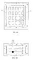
- FIGS. 4A–4BThe location of the RFID sensor coils 26 , 28 within the key control system is shown in FIGS. 4A–4B .
- FIG. 4Aillustrates a top view of the shielded key control enclosure 12 also showing a plurality of slots 16 ;
- FIG. 4Billustrates an end view of the system.
- two RFID sensor coils 26 , 28are placed near the left side and right side of shielded key control enclosure 12 , respectively.
- the sensor near the left sideis denoted as RFID coil A 26 ;
- the sensor near the right sideis denoted as RFID coil B 28 .
- These two RFID coils 26 , 28work in tandem to create a magnetic sensing field 32 between them, as indicated in both FIGS. 4A and 4B .
- the key tags 14are inserted through the key tag slots 16 as shown in the end view of FIG. 4B .
- the RFID tag 30is contained on/in the portion of the key tag 14 inside the shielded enclosure 12 .
- the RFID coil pair 26 , 28creates a magnetic field 32 that is normal to the surface of the key tag 14 , yielding maximum induced current in the RFID tag 30 .
- the shielded enclosure 12either is constructed of metal or is made conducting so that it acts as a shield.
- RFID tags 30are interrogated at frequencies up to a few gigahertz (GHz).
- GHzgigahertz
- the key tag slots 16are electrically small, i.e., sized much less than the electromagnetic wavelength, then the magnetic field will be contained within the key control enclosure 12 .
- the wavelengthequals the speed of light divided by the frequency. At 1 GHz, the wavelength is approximately 1 foot.
- a typical key tag slot 16is no longer than one inch. At lower frequencies, the wavelength increases and the key tag slot 16 is thus even more electrically small.
- Containing the magnetic RFID interrogation field as described aboveis preferred because the presence detectors 22 and tag identification sensor work in tandem to know that key tags 14 are present and in which slot 16 they reside. If the magnetic interrogation field was not carefully confined, the potential then exists to pick up and read the ID code of tags outside, but nearby the key control enclosure 12 . This would disrupt the logic processing outlined in FIG. 2 and result in key tags 14 being marked as ambiguous when the key control system is used with the presence of extra key tags nearby. However, while it is not preferred, it is possible to construct functionally useful key control systems that do not require the careful magnetic field confinement. These key control systems, while not technically superior, may be less costly to build and thus ultimately more deployable.
- the extraneous key tags being sensedmay be contained in a neighboring key tag enclosure.
- the computercould compare the database of key tags in the neighboring enclosures to know that the extraneously detected key tags are already accounted for and thus were not just inserted into its slots.
- FIGS. 5–8A first approach is to utilize an electrical switch 40 as shown in FIG. 5 .
- the switch 50is placed on the backplane 24 in such a manner than when the key tag 14 is inserted through slot 16 in top tray 15 , the bottom portion of the key tag 14 will close the lever 44 on the switch, thus electrically closing the switch.
- a tag alignment device 42may be necessary to ensure that the inserted tag 14 properly engages/closes the switch 40 . Note that mounting the switch vertically allows the switch to be closed for a range of insertion amounts.
- a second approach that is related to the firstis to simply make the end 34 of the key tag 14 metallic and place a pair of contacts 46 vertically on the backplane 24 as shown in FIG. 6 .
- the insertion of the key tag 14 through slot 16 in top tray 15will complete the circuit for a range of insertion amounts.
- a third approachis to utilize a photo-conducting switch 50 as shown in FIG. 7 .
- Photo conducting diodes and photo conducting transistorscan be used as a photo-conducting switch.
- an LED 52is mounted and on the other side a photo-conducting switch 50 is mounted. If the key tag 14 is opaque, tag insertion through slot 16 in top tray 15 will block the light and open the switch 50 .
- This switch operation stateis opposite from the first two approaches, i.e., inserted tag yields open switch, instead of closed switch.
- the key control systemcan be designed to recognize either open or closed switches as a tag present or absent condition.
- a fourth approachis to utilize a magnetic reed switch 60 as shown in FIG. 8 .
- the reed switch 60is placed on the backplane 24 below the key tag slot 16 .
- the bottom portion 64 of the key tag 14contains embedded magnetic material. When the magnetic material is close to the reed switch 60 , the reed switch 60 closes. The range of operation is determined by the strength of the embedded magnetic material.
- the switch or other sensor used for presence/absence detectors 22can be configured in a matrix configuration.
- the circuit shown in FIG. 9teaches the basic concept of encoding switches into a matrix. The circuit is improved by adding components to handle switch-bouncing effects. One of skill in the art can recognize that this is the basic concept of keyboard encoding and there are numerous circuit configurations to achieve switch encoding of a matrix. One of skill in the art can also configure similar matrix configurations to encode the other sensors mentioned.
- Two rows and columns of presence detectors 22are depicted in FIG. 9 to simplify the schematic The presence detectors are labled A, B, C, D in the figure. Row selection line 23 leading from decoder 31 and column selection line 25 leading from multiplexer 33 are also illustrated. The presence or absence of a key tag 14 is indicated by SW STATE output 35 from multiplexer 33 .
- the approachis scalable to multiple rows and columns.
- a first approachis to place key tag receptacles 70 onto the backplane 24 below each key tag slot 16 , as illustrated in FIGS. 10A–10B .
- These receptacles 70can be fabricated from plastic using injection molding. They can be fabricated in one piece per key tag slot 16 as shown in FIGS. 10A–10B or in one long piece with many receptacles per column of key tag slots (not illustrated).
- the location of attachments to the backplane 24are indicated by reference numerals 68 .
- a second optionis to construct alignment devices 72 that can be attached to the bottom or top of the top tray as shown in FIGS. 11A–11B .
- These alignment devices 72can also be fabricated from plastic using injection molding. These parts would most likely be configured as long pieces for use on a column of key tag slots.
- the top tray attachment locationsare indicated by reference numerals 74 .
- Another optionis to simply incorporate the alignment devices and the top inventory tray into a single, injection-molded part. This has the promise of simplifying construction and potentially reducing costs.
- Further optionsinclude simply using multiple, vertically offset inventory trays to keep the key tags aligned when inserted. Additionally, a slot can be made in a backplane below each key tag slot to allow the key tag to pass through the backplane to ensure alignment. Using non-metallic materials such as plastic for these alignment devices causes no real problem for the magnetic RFID tag sensors.
- FIG. 12shows a key tag 80 that includes an LED circuit 82 .
- the LED circuit 82includes a power source and a current limiting device as is known in the art.
- This embodimentillustrates an inductive RFID tag coil 88 concept.
- the interrogating magnetic fieldpowers and communicates with the RFID addressable switch 84 .
- Using an RFID addressable switch 84allows the interrogating field to selectively turn on the LED circuit 82 on the desired key tag 80 .
- Other possible embedded indicatorscan include an audio buzzer and/or vibrating shaker.
- the ambiguity problemis overcome because in general the system does not need to know the location of each key tag 80 . When the user wants to remove a specific key tag, the system can turn on the indicator 82 , e.g., LED, on the desired key tag 80 .
- FIG. 13One alternative embodiment is illustrated in FIG. 13 .
- One criterion for alternative sensor approachesis read range, and the read range of capacitive tag RF tag sensors 92 , 94 is sufficient to cover typical key tag enclosures 12 .
- the RFID coils A 26 and B 28are replaced by RFID capacitive plates 96 , 98 and their location is moved to properly orient them with respect to the now capacitive RFID tags 90 on the key tags.
- the approach described hereinuses one global sensor apparatus to interrogate all of the inserted key tags. While the single key tag sensor is the preferred embodiment, it may also be feasible to partition the enclosure into sub-enclosures. In that situation, one key tag sensor apparatus will then be used for each sub-enclosure.
- the inventor's prior object tracking patentsU.S. Pat. Nos. 5,801,628 and 6,075,441, and RF key control system patent, U.S. Pat. No. 6,204,764, have described key control systems that utilize a one-wire memory device on key tags.
- the construction techniquesare covered in these prior patents.
- the disclosures of each of these three prior patentsare incorporated by reference herein in their entirety.
- the separated presence detection and identification mechanism described hereinis also applicable to a one-wire memory device.
- the one-wire memory devicecan be attached to a single, common bus on the backplane. This would allow all of the memory devices with unique IDs to be read serially.
- a matrix of presence detectorscan also be placed on the backplane as described herein to determine which key tag slots contain key tags.
- multiple busescan be utilized. For example, there can be one bus per row or column, or perhaps one bus per zone of the backplane.
- tagscould be entered by entering a tag ID first, and then inserting the tag into the key control system for the system to assign the next RFID or button number to the entered tag ID.
- the tag IDin this case is an identifier that the user enters into the system to identify a particular tag.
- This readercan also be used for user access cards to log into the system.
- An additional secure embodimentis to utilize assigned key tag slots.
- the system of the key control systemwill not need presence detectors because location is assumed. If the user places the tag in the wrong slot, the system will still log the tag in as returned. If the user tries to take a key tag not requested, the key control system will still log it out to him because the global key tag scan notices its absence. Hence, the key control system is still secure, even though locations may be ambiguous.
- the aforementioned embedded indicator approachcan be utilized to identify the requested key tag.
- the invention described hereinhas used the term “key control enclosure” throughout.
- the preferred embodimentis for the key control enclosure to be a drawer.
- Other embodimentsare vertically mounted cabinets, mobile carriers, or an open range embodiment.
- the objects being trackedhave been described herein specifically as keys on key tags. Again, this is a preferred embodiment. However, various objects can be tracked using the approach described herein. For example, drugs, jewelry, portable bar code scanners, communication radios, etc. can use the teachings of this invention.
Landscapes
- Engineering & Computer Science (AREA)
- Physics & Mathematics (AREA)
- General Physics & Mathematics (AREA)
- Automation & Control Theory (AREA)
- Electromagnetism (AREA)
- Theoretical Computer Science (AREA)
- Computer Security & Cryptography (AREA)
- Health & Medical Sciences (AREA)
- Toxicology (AREA)
- Computer Networks & Wireless Communication (AREA)
- General Health & Medical Sciences (AREA)
- Artificial Intelligence (AREA)
- Computer Vision & Pattern Recognition (AREA)
Abstract
Description
Claims (40)
Priority Applications (1)
| Application Number | Priority Date | Filing Date | Title |
|---|---|---|---|
| US10/924,330US7049961B2 (en) | 2001-04-26 | 2004-08-23 | Key control system using separated ID and location detection mechanisms |
Applications Claiming Priority (3)
| Application Number | Priority Date | Filing Date | Title |
|---|---|---|---|
| US28676001P | 2001-04-26 | 2001-04-26 | |
| US10/133,130US6812838B1 (en) | 2001-04-26 | 2002-04-26 | Key control system using separate ID and location detection mechanisms |
| US10/924,330US7049961B2 (en) | 2001-04-26 | 2004-08-23 | Key control system using separated ID and location detection mechanisms |
Related Parent Applications (1)
| Application Number | Title | Priority Date | Filing Date |
|---|---|---|---|
| US10/133,130ContinuationUS6812838B1 (en) | 2001-04-26 | 2002-04-26 | Key control system using separate ID and location detection mechanisms |
Publications (2)
| Publication Number | Publication Date |
|---|---|
| US20050024211A1 US20050024211A1 (en) | 2005-02-03 |
| US7049961B2true US7049961B2 (en) | 2006-05-23 |
Family
ID=33302474
Family Applications (2)
| Application Number | Title | Priority Date | Filing Date |
|---|---|---|---|
| US10/133,130Expired - LifetimeUS6812838B1 (en) | 2001-04-26 | 2002-04-26 | Key control system using separate ID and location detection mechanisms |
| US10/924,330Expired - LifetimeUS7049961B2 (en) | 2001-04-26 | 2004-08-23 | Key control system using separated ID and location detection mechanisms |
Family Applications Before (1)
| Application Number | Title | Priority Date | Filing Date |
|---|---|---|---|
| US10/133,130Expired - LifetimeUS6812838B1 (en) | 2001-04-26 | 2002-04-26 | Key control system using separate ID and location detection mechanisms |
Country Status (1)
| Country | Link |
|---|---|
| US (2) | US6812838B1 (en) |
Cited By (8)
| Publication number | Priority date | Publication date | Assignee | Title |
|---|---|---|---|---|
| US20070194889A1 (en)* | 2006-02-03 | 2007-08-23 | Bailey Daniel V | Security Provision in Standards-Compliant RFID Systems |
| US20070216532A1 (en)* | 2004-05-24 | 2007-09-20 | Lansdowne David C | Identification of Biological Samples |
| US20080042839A1 (en)* | 2004-04-07 | 2008-02-21 | Matthias Grater | Device and Method for Identifying, Locating and Tracking Objects on Laboratory Equipment |
| US20080088454A1 (en)* | 2006-10-13 | 2008-04-17 | Rfid De Mexico, S.A. De C.V. | Item tracking system |
| US20110012735A1 (en)* | 2009-06-15 | 2011-01-20 | Jerry Kestenbaum | Item storage and tracking system |
| US8194045B1 (en) | 2005-01-27 | 2012-06-05 | Singleton Technology, Llc | Transaction automation and archival system using electronic contract disclosure units |
| US8228299B1 (en) | 2005-01-27 | 2012-07-24 | Singleton Technology, Llc | Transaction automation and archival system using electronic contract and disclosure units |
| US11398122B2 (en) | 2017-04-28 | 2022-07-26 | 1 Micro, LLC | Passenger authentication system for a transportation service vehicle |
Families Citing this family (74)
| Publication number | Priority date | Publication date | Assignee | Title |
|---|---|---|---|---|
| US7116228B1 (en)* | 2001-02-20 | 2006-10-03 | Key Control Holding, Inc. | Asset management system |
| US7336174B1 (en) | 2001-08-09 | 2008-02-26 | Key Control Holding, Inc. | Object tracking system with automated system control and user identification |
| WO2003046824A2 (en)* | 2001-11-21 | 2003-06-05 | Marconi Intellectual Property (Us) Inc. | Wireless communication device interconnectivity |
| US20030117281A1 (en)* | 2001-12-21 | 2003-06-26 | Timur Sriharto | Dynamic control containment unit |
| WO2004012893A1 (en)* | 2002-08-02 | 2004-02-12 | Hy-Ko Products Company | Object identification system |
| CA2496240C (en)* | 2002-08-19 | 2014-07-15 | Key Systems, Inc. | Tangible security asset management system and methods thereof |
| US20050104729A1 (en)* | 2003-11-14 | 2005-05-19 | Grant Burton F. | Credit card minder |
| JP4194497B2 (en)* | 2004-01-20 | 2008-12-10 | キヤノン株式会社 | Article storage apparatus, article storage method thereof, and control program |
| US7753272B2 (en)* | 2004-04-23 | 2010-07-13 | Winware, Inc. | Object tracking in an enclosure |
| US7669765B2 (en)* | 2004-04-23 | 2010-03-02 | Winware, Inc. | RFID switching |
| US7339476B2 (en)* | 2004-11-10 | 2008-03-04 | Rockwell Automation Technologies, Inc. | Systems and methods that integrate radio frequency identification (RFID) technology with industrial controllers |
| US7551081B2 (en) | 2004-11-10 | 2009-06-23 | Rockwell Automation Technologies, Inc. | Systems and methods that integrate radio frequency identification (RFID) technology with agent-based control systems |
| US8156899B2 (en) | 2004-12-13 | 2012-04-17 | Innovive Inc. | Containment systems and components for animal husbandry: nested covers |
| US20070169715A1 (en) | 2004-12-13 | 2007-07-26 | Innovive Inc. | Containment systems and components for animal husbandry |
| US7319398B2 (en)* | 2004-12-15 | 2008-01-15 | Innerspace Corporation | Reconfigurable and replaceable RFID antenna network |
| US7271724B2 (en)* | 2005-03-28 | 2007-09-18 | Accenture Global Services Gmbh | Interfering smart shelf |
| US20060232412A1 (en)* | 2005-04-15 | 2006-10-19 | Jorge Tabacman & Associates P/L | Intelligent reader system and method for identifying and tracking goods and materials transported in pallets, including but not limited to scaffolding materials |
| US7636044B1 (en) | 2005-05-13 | 2009-12-22 | Rockwell Automation Technologies, Inc. | RFID tag programming, printing application, and supply chain/global registration architecture |
| US7954455B2 (en) | 2005-06-14 | 2011-06-07 | Innovive, Inc. | Cage cover with filter, shield and nozzle receptacle |
| US7411508B2 (en)* | 2005-06-17 | 2008-08-12 | Perkinemer Las, Inc. | Methods and systems for locating and identifying labware using radio-frequency identification tags |
| US7616117B2 (en) | 2005-07-19 | 2009-11-10 | Rockwell Automation Technologies, Inc. | Reconciliation mechanism using RFID and sensors |
| US7388491B2 (en) | 2005-07-20 | 2008-06-17 | Rockwell Automation Technologies, Inc. | Mobile RFID reader with integrated location awareness for material tracking and management |
| US7764191B2 (en) | 2005-07-26 | 2010-07-27 | Rockwell Automation Technologies, Inc. | RFID tag data affecting automation controller with internal database |
| US8260948B2 (en) | 2005-08-10 | 2012-09-04 | Rockwell Automation Technologies, Inc. | Enhanced controller utilizing RFID technology |
| US7648065B2 (en)* | 2005-08-31 | 2010-01-19 | The Stanley Works | Storage cabinet with improved RFID antenna system |
| US7586413B2 (en)* | 2005-09-01 | 2009-09-08 | Assa Abloy Ab | Human feedback using parasitic power harvesting of RFID tags |
| US7510110B2 (en) | 2005-09-08 | 2009-03-31 | Rockwell Automation Technologies, Inc. | RFID architecture in an industrial controller environment |
| US7931197B2 (en) | 2005-09-20 | 2011-04-26 | Rockwell Automation Technologies, Inc. | RFID-based product manufacturing and lifecycle management |
| US7446662B1 (en) | 2005-09-26 | 2008-11-04 | Rockwell Automation Technologies, Inc. | Intelligent RFID tag for magnetic field mapping |
| US8025227B2 (en) | 2005-09-30 | 2011-09-27 | Rockwell Automation Technologies, Inc. | Access to distributed databases via pointer stored in RFID tag |
| US7862434B2 (en)* | 2006-02-07 | 2011-01-04 | The Kendall 1987 Revocable Trust | Multi-sensor system for counting and identifying objects in close proximity |
| US7394380B2 (en)* | 2006-02-16 | 2008-07-01 | International Business Machines Corporation | System and method for improved item tracking |
| DE102006025000A1 (en)* | 2006-03-03 | 2007-09-06 | Hamedani, Soheil | Precious metal object with RFID identifier |
| US7528720B2 (en)* | 2006-04-28 | 2009-05-05 | Motorola, Inc. | Radio frequency identification tag-based task effectuation method and apparatus |
| US7411502B2 (en)* | 2006-04-28 | 2008-08-12 | Motorola, Inc. | Radio frequency identification tag based tray and tray receiving method and apparatus |
| MX2009000087A (en)* | 2006-06-21 | 2009-03-20 | Neology Inc | Systems and methods for interrogator multiple radio frequency identification enabled documents. |
| US7768404B2 (en)* | 2006-06-30 | 2010-08-03 | RFID Mexico, S.A. DE C.V. | System and method for optimizing resources in a supply chain using RFID and artificial intelligence |
| CA2660950C (en)* | 2006-08-17 | 2015-02-10 | Innovive, Inc. | Single-use rodent containment cage |
| DE102007013237A1 (en)* | 2007-03-15 | 2008-09-18 | Joint Analytical Systems Gmbh | storage system |
| US9155283B2 (en)* | 2007-04-11 | 2015-10-13 | Innovive, Inc. | Animal husbandry drawer caging |
| US20100213264A1 (en)* | 2007-10-16 | 2010-08-26 | Confidex Oy | Method for rfid tagging |
| US10070888B2 (en) | 2008-10-03 | 2018-09-11 | Femasys, Inc. | Methods and devices for sonographic imaging |
| US8341040B1 (en)* | 2008-10-07 | 2012-12-25 | Amazon Technologies, Inc. | System and method for stow management of similar items |
| US20100096455A1 (en) | 2008-10-16 | 2010-04-22 | Merrick Systems Inc. | Edge mounted rfid tag |
| US8414471B2 (en) | 2008-10-28 | 2013-04-09 | Mobile Aspects, Inc. | Endoscope storage cabinet, tracking system, and signal emitting member |
| JP5519687B2 (en)* | 2008-11-07 | 2014-06-11 | イノビーブ,インコーポレイティド | Rack system for livestock and monitoring method |
| EP2312332B1 (en)* | 2009-10-15 | 2012-12-19 | Fraunhofer-Gesellschaft zur Förderung der angewandten Forschung e.V. | Method for detecting at least one object and radio node network |
| WO2012051124A2 (en)* | 2010-10-11 | 2012-04-19 | Innovive, Inc. | Rodent containment cage monitoring apparatus and methods |
| EP2700210B1 (en)* | 2011-04-20 | 2020-12-09 | Sony Network Communications Europe B.V. | Methods, systems and computer program products for anonymous tracking of objects |
| US8695878B2 (en) | 2011-08-31 | 2014-04-15 | Djb Group Llc | Shelf-monitoring system |
| WO2014118727A1 (en)* | 2013-01-31 | 2014-08-07 | Tecniplast S.P.A. | System and method for automatically detecting the presence of cages in the shelf of a facility |
| US20140263634A1 (en)* | 2013-03-15 | 2014-09-18 | Shazi Iqbal | Specimen reader employing optical and rfid scanning |
| US10095898B2 (en)* | 2013-03-15 | 2018-10-09 | Shazi Iqbal | Method of specimen tracking via barcode and RFID correlation at accession time |
| US10459410B2 (en) | 2013-03-15 | 2019-10-29 | Shazi Iqbal | Automatic tracking of a specimen holder moved from one specimen rack to another |
| WO2015002843A1 (en) | 2013-07-01 | 2015-01-08 | Innovive, Inc. | Cage rack monitoring apparatus and methods |
| US9892618B2 (en) | 2013-08-09 | 2018-02-13 | Mobile Aspects, Inc. | Signal emitting member attachment system and arrangement |
| US9348013B2 (en) | 2013-09-18 | 2016-05-24 | Mobile Aspects, Inc. | Item hanger arrangement, system, and method |
| US9224124B2 (en) | 2013-10-29 | 2015-12-29 | Mobile Aspects, Inc. | Item storage and tracking cabinet and arrangement |
| US9922304B2 (en) | 2013-11-05 | 2018-03-20 | Deroyal Industries, Inc. | System for sensing and recording consumption of medical items during medical procedure |
| US10922647B2 (en) | 2014-10-02 | 2021-02-16 | Deroyal Industries, Inc. | System for prevention of fraud in accounting for utilization of medical items |
| CA2929604C (en) | 2013-11-05 | 2020-09-15 | Deroyal Industries, Inc. | Sensing and recording consumption of medical items during medical procedure |
| US10152688B2 (en) | 2014-05-15 | 2018-12-11 | Deroyal Industries, Inc. | System for sensing and recording information regarding medical items in a medical facility |
| US10034400B2 (en) | 2013-12-04 | 2018-07-24 | Mobile Aspects, Inc. | Item storage arrangement system and method |
| FR3017643B1 (en)* | 2014-02-17 | 2016-05-20 | Sam Outil | MANAGING THE STORAGE AND STORAGE OF OBJECTS, IN PARTICULAR TOOLS, BY RFID-TYPE WIRELESS MEANS, ESPECIALLY OF BREAKER TYPE AND RFID CHIP |
| EP3177134B1 (en) | 2014-07-25 | 2022-08-17 | Innovive, Inc. | Animal containment enrichment compositions and methods |
| CA2960823C (en)* | 2014-09-11 | 2021-03-23 | Deroyal Industries, Inc. | System for tracking utilization and consumption of medical items in a medical facility and maintaining a chain of custody based thereon |
| DE102015007108A1 (en)* | 2015-04-28 | 2016-11-03 | Leopold Kostal Gmbh & Co. Kg | Operating system for a motor vehicle and method for operating such an operating system |
| JP6554315B2 (en)* | 2015-05-12 | 2019-07-31 | 株式会社Nttファシリティーズ | Authentication key management system, authentication key management method and program |
| TWI616829B (en)* | 2015-08-21 | 2018-03-01 | 緯創資通股份有限公司 | Method, system, and computer-readable recording medium for object location tracking |
| WO2018068838A1 (en)* | 2016-10-11 | 2018-04-19 | Hp Indigo B.V. | Tracking removable components using sectors |
| JP7051883B2 (en) | 2016-10-28 | 2022-04-11 | イノバイブ, インコーポレイテッド | Metabolic cage |
| CN108960369B (en)* | 2018-07-02 | 2022-01-25 | 京东方科技集团股份有限公司 | Electronic price tag, electronic price tag system and method for updating electronic price tag |
| US11861961B2 (en)* | 2018-08-22 | 2024-01-02 | Inspectrealestate.Com.Au Pty Ltd | Key management system |
| BE1029027B1 (en)* | 2021-01-18 | 2022-08-22 | Codek Bv | KEY MANAGEMENT SYSTEM |
Citations (65)
| Publication number | Priority date | Publication date | Assignee | Title |
|---|---|---|---|---|
| US527589A (en) | 1894-10-16 | Device for tradesmen s use | ||
| US2971806A (en) | 1957-07-18 | 1961-02-14 | Norman H Andreasen | In-and-out pager cabinet |
| US3648241A (en) | 1968-03-22 | 1972-03-07 | Elecompack Co Ltd | Stationary stack assembly with remotely controlled access |
| GB1364535A (en) | 1971-09-13 | 1974-08-21 | Cannon Electric Great Britain | Electrical connector |
| US4060795A (en) | 1973-02-23 | 1977-11-29 | Hitachi, Ltd. | Scanning system |
| US4267942A (en) | 1979-06-20 | 1981-05-19 | John B. Wick, Jr. | Pharmaceutical dispensing cabinet |
| US4519522A (en) | 1981-07-06 | 1985-05-28 | Photo Vending Corporation | Apparatus and method for storing and retrieving articles |
| US4527578A (en) | 1983-09-26 | 1985-07-09 | Ryko Manufacturing Company | Automatic vehicle washer |
| US4549170A (en) | 1982-05-17 | 1985-10-22 | Serres Bernard M | System for managing a panel of objects such as keys |
| US4575719A (en) | 1983-10-14 | 1986-03-11 | Avicom International, Inc. | Controlled access storage system |
| US4595922A (en) | 1984-12-10 | 1986-06-17 | Cobb Richard G | Method and apparatus for monitoring keys and other articles |
| US4635053A (en) | 1983-09-06 | 1987-01-06 | Banks Edward J K | Apparatus for supervising access to individual items |
| US4636634A (en) | 1984-08-28 | 1987-01-13 | Veeco Integrated Automation, Inc. | Apparatus with intelligent bins indicating the presence and identity of stored coded articles |
| US4636950A (en) | 1982-09-30 | 1987-01-13 | Caswell Robert L | Inventory management system using transponders associated with specific products |
| US4661806A (en) | 1985-05-10 | 1987-04-28 | Peters Gilbert A | Computer controlled key management system |
| US4663621A (en) | 1984-03-30 | 1987-05-05 | Field David J | Medicine cabinet |
| US4673915A (en) | 1985-12-12 | 1987-06-16 | Cobb Richard G | Key storage and monitoring system |
| US4783655A (en) | 1984-12-10 | 1988-11-08 | Richard G. Cobb | Article monitoring system with printing capability |
| US4812985A (en) | 1986-09-15 | 1989-03-14 | Ja-Pac, Inc | Article storage and retrieval system |
| US4814592A (en) | 1986-05-29 | 1989-03-21 | Videomat Associates | Apparatus and method for storing and retrieving articles |
| US4839875A (en) | 1986-05-19 | 1989-06-13 | Anritsu Corporation | Technique for automatic tracking of cassette rentals and managing of information related thereto |
| US4845492A (en) | 1984-12-10 | 1989-07-04 | Richard G. Cobb | Article monitoring system with printing capability |
| US4885571A (en) | 1986-04-15 | 1989-12-05 | B. I. Incorperated | Tag for use with personnel monitoring system |
| US4896024A (en) | 1987-10-19 | 1990-01-23 | Diebold, Incorporated | Apparatus for dispensing and accepting return of reusable articles |
| US4918432A (en) | 1988-09-27 | 1990-04-17 | B. I. Incorporated | House arrest monitoring system |
| US4929819A (en) | 1988-12-12 | 1990-05-29 | Ncr Corporation | Method and apparatus for customer performed article scanning in self-service shopping |
| US4967906A (en) | 1987-10-19 | 1990-11-06 | Diebold, Incorporated | Apparatus for dispensing and accepting return of reusable articles |
| US5038023A (en) | 1989-06-28 | 1991-08-06 | C. Itoh Information Systems Development, Inc. | System for storing and monitoring bar coded articles such as keys in a drawer |
| US5172829A (en) | 1991-09-26 | 1992-12-22 | Siemens Nixdorf Information Systems, Inc. | Automated key dispenser |
| US5287414A (en) | 1991-06-21 | 1994-02-15 | Esselte Pendaflex Corporation | Coded file locator system |
| WO1995004324A1 (en) | 1993-07-29 | 1995-02-09 | Morse Watchmans, Inc. | System and device for storing objects |
| US5404384A (en) | 1993-01-25 | 1995-04-04 | Medselect Systems, Inc. | Inventory monitoring apparatus employing counter for adding and subtracting objects being monitored |
| WO1995012858A1 (en) | 1993-11-04 | 1995-05-11 | The General Hospital Corporation | Managing an inventory of devices |
| US5426284A (en) | 1990-12-12 | 1995-06-20 | Engineered Data Products, Inc. | Apparatus for locating and tracking information storage items using predefined labels |
| US5533079A (en) | 1993-01-25 | 1996-07-02 | Medselect Systems, Inc. | Inventory monitoring apparatus |
| US5671362A (en) | 1995-04-04 | 1997-09-23 | Cowe; Alan B. | Materials monitoring systems, materials management systems and related methods |
| US5689238A (en) | 1996-03-08 | 1997-11-18 | Lucent Technologies, Inc. | Object locator system and methods therefor |
| US5703785A (en) | 1994-08-19 | 1997-12-30 | Bluemel; Mark R. | Inventory control apparatus and method of using same |
| US5721531A (en) | 1995-06-28 | 1998-02-24 | The Whitaker Corporation | Monitoring arrangement for electronic file folder locator system |
| US5739765A (en) | 1995-01-27 | 1998-04-14 | Steelcase Inc. | File folders for use in an electronic file locating and tracking system |
| US5771003A (en) | 1996-09-24 | 1998-06-23 | Elenco Electronics, Inc. | Locating system and process |
| US5777884A (en) | 1995-10-16 | 1998-07-07 | Minnesota Mining And Manufacturing Company | Article inventory tracking and control system |
| US5794213A (en)* | 1995-06-06 | 1998-08-11 | Markman; Herbert L. | Method and apparatus for reforming grouped items |
| US5801628A (en) | 1995-09-08 | 1998-09-01 | Key-Trak, Inc. | Inventoriable-object control and tracking system |
| US5836002A (en) | 1995-06-01 | 1998-11-10 | Morstein; Jason | Anti-theft device |
| US5905653A (en) | 1994-07-14 | 1999-05-18 | Omnicell Technologies, Inc. | Methods and devices for dispensing pharmaceutical and medical supply items |
| US5936527A (en) | 1998-02-10 | 1999-08-10 | E-Tag Systems, Inc. | Method and apparatus for locating and tracking documents and other objects |
| US5957372A (en) | 1996-07-12 | 1999-09-28 | Diebold, Incorporated | Apparatus and method for accepting return of unused medical items |
| US5963134A (en) | 1997-07-24 | 1999-10-05 | Checkpoint Systems, Inc. | Inventory system using articles with RFID tags |
| US5961036A (en) | 1996-07-12 | 1999-10-05 | Diebold, Incorporated | Apparatus and method for accepting return of unused medical items |
| US5971593A (en) | 1994-12-16 | 1999-10-26 | Diebold, Incorporated | Dispensing system for medical items |
| USRE36530E (en)* | 1993-06-25 | 2000-01-25 | Precision Tracking Fm, Inc. | Method for receiving and transmitting optical data and control information to and from remotely located receivers and transmitters in an optical locator system |
| WO2000016282A1 (en) | 1998-09-11 | 2000-03-23 | Key-Trak, Inc. | Objet carriers for an object control and tracking system |
| WO2000016564A1 (en) | 1998-09-11 | 2000-03-23 | Key-Trak, Inc. | Object control and tracking system with zonal transition detection |
| WO2000016280A1 (en) | 1998-09-11 | 2000-03-23 | Key-Trak, Inc. | Object tracking system with non-contact object detection and identification |
| WO2000016284A1 (en) | 1998-09-11 | 2000-03-23 | Key-Trak, Inc. | Tamper detection and prevention for an object control and tracking system |
| WO2000016281A1 (en) | 1998-09-11 | 2000-03-23 | Key-Trak, Inc. | Mobile object tracking system |
| US6069563A (en) | 1996-03-05 | 2000-05-30 | Kadner; Steven P. | Seal system |
| US6075441A (en) | 1996-09-05 | 2000-06-13 | Key-Trak, Inc. | Inventoriable-object control and tracking system |
| US6148271A (en) | 1998-01-14 | 2000-11-14 | Silicon Pie, Inc. | Speed, spin rate, and curve measuring device |
| WO2001075811A1 (en) | 2000-03-31 | 2001-10-11 | Traka Limited | Equipment monitoring method and apparatus |
| US6707381B1 (en) | 2001-06-26 | 2004-03-16 | Key-Trak, Inc. | Object tracking method and system with object identification and verification |
| US6714121B1 (en)* | 1999-08-09 | 2004-03-30 | Micron Technology, Inc. | RFID material tracking method and apparatus |
| US6745366B1 (en) | 2000-11-21 | 2004-06-01 | Daewoo Electronics Corporation | Error correcting method and apparatus for N:N+1 channel codes |
| US6788997B1 (en) | 1998-06-01 | 2004-09-07 | Medselect, Inc. | Medical cabinet with adjustable drawers |
- 2002
- 2002-04-26USUS10/133,130patent/US6812838B1/ennot_activeExpired - Lifetime
- 2004
- 2004-08-23USUS10/924,330patent/US7049961B2/ennot_activeExpired - Lifetime
Patent Citations (72)
| Publication number | Priority date | Publication date | Assignee | Title |
|---|---|---|---|---|
| US527589A (en) | 1894-10-16 | Device for tradesmen s use | ||
| US2971806A (en) | 1957-07-18 | 1961-02-14 | Norman H Andreasen | In-and-out pager cabinet |
| US3648241A (en) | 1968-03-22 | 1972-03-07 | Elecompack Co Ltd | Stationary stack assembly with remotely controlled access |
| GB1364535A (en) | 1971-09-13 | 1974-08-21 | Cannon Electric Great Britain | Electrical connector |
| US4060795A (en) | 1973-02-23 | 1977-11-29 | Hitachi, Ltd. | Scanning system |
| US4267942A (en) | 1979-06-20 | 1981-05-19 | John B. Wick, Jr. | Pharmaceutical dispensing cabinet |
| US4519522A (en) | 1981-07-06 | 1985-05-28 | Photo Vending Corporation | Apparatus and method for storing and retrieving articles |
| US4549170A (en) | 1982-05-17 | 1985-10-22 | Serres Bernard M | System for managing a panel of objects such as keys |
| US4636950A (en) | 1982-09-30 | 1987-01-13 | Caswell Robert L | Inventory management system using transponders associated with specific products |
| US4635053A (en) | 1983-09-06 | 1987-01-06 | Banks Edward J K | Apparatus for supervising access to individual items |
| US4527578A (en) | 1983-09-26 | 1985-07-09 | Ryko Manufacturing Company | Automatic vehicle washer |
| US4575719A (en) | 1983-10-14 | 1986-03-11 | Avicom International, Inc. | Controlled access storage system |
| US4663621A (en) | 1984-03-30 | 1987-05-05 | Field David J | Medicine cabinet |
| US4636634A (en) | 1984-08-28 | 1987-01-13 | Veeco Integrated Automation, Inc. | Apparatus with intelligent bins indicating the presence and identity of stored coded articles |
| US4845492A (en) | 1984-12-10 | 1989-07-04 | Richard G. Cobb | Article monitoring system with printing capability |
| US4783655A (en) | 1984-12-10 | 1988-11-08 | Richard G. Cobb | Article monitoring system with printing capability |
| US4595922A (en) | 1984-12-10 | 1986-06-17 | Cobb Richard G | Method and apparatus for monitoring keys and other articles |
| US4661806A (en) | 1985-05-10 | 1987-04-28 | Peters Gilbert A | Computer controlled key management system |
| US4673915A (en) | 1985-12-12 | 1987-06-16 | Cobb Richard G | Key storage and monitoring system |
| US4885571A (en) | 1986-04-15 | 1989-12-05 | B. I. Incorperated | Tag for use with personnel monitoring system |
| US4839875A (en) | 1986-05-19 | 1989-06-13 | Anritsu Corporation | Technique for automatic tracking of cassette rentals and managing of information related thereto |
| US4814592A (en) | 1986-05-29 | 1989-03-21 | Videomat Associates | Apparatus and method for storing and retrieving articles |
| US4812985A (en) | 1986-09-15 | 1989-03-14 | Ja-Pac, Inc | Article storage and retrieval system |
| US4967906A (en) | 1987-10-19 | 1990-11-06 | Diebold, Incorporated | Apparatus for dispensing and accepting return of reusable articles |
| US4896024A (en) | 1987-10-19 | 1990-01-23 | Diebold, Incorporated | Apparatus for dispensing and accepting return of reusable articles |
| US4918432A (en) | 1988-09-27 | 1990-04-17 | B. I. Incorporated | House arrest monitoring system |
| US4929819A (en) | 1988-12-12 | 1990-05-29 | Ncr Corporation | Method and apparatus for customer performed article scanning in self-service shopping |
| US5038023A (en) | 1989-06-28 | 1991-08-06 | C. Itoh Information Systems Development, Inc. | System for storing and monitoring bar coded articles such as keys in a drawer |
| US5426284A (en) | 1990-12-12 | 1995-06-20 | Engineered Data Products, Inc. | Apparatus for locating and tracking information storage items using predefined labels |
| US5287414A (en) | 1991-06-21 | 1994-02-15 | Esselte Pendaflex Corporation | Coded file locator system |
| US5172829A (en) | 1991-09-26 | 1992-12-22 | Siemens Nixdorf Information Systems, Inc. | Automated key dispenser |
| US5404384A (en) | 1993-01-25 | 1995-04-04 | Medselect Systems, Inc. | Inventory monitoring apparatus employing counter for adding and subtracting objects being monitored |
| US5533079A (en) | 1993-01-25 | 1996-07-02 | Medselect Systems, Inc. | Inventory monitoring apparatus |
| USRE36530E (en)* | 1993-06-25 | 2000-01-25 | Precision Tracking Fm, Inc. | Method for receiving and transmitting optical data and control information to and from remotely located receivers and transmitters in an optical locator system |
| WO1995004324A1 (en) | 1993-07-29 | 1995-02-09 | Morse Watchmans, Inc. | System and device for storing objects |
| WO1995012858A1 (en) | 1993-11-04 | 1995-05-11 | The General Hospital Corporation | Managing an inventory of devices |
| US5434775A (en) | 1993-11-04 | 1995-07-18 | The General Hospital Corporation | Managing an inventory of devices |
| US5905653A (en) | 1994-07-14 | 1999-05-18 | Omnicell Technologies, Inc. | Methods and devices for dispensing pharmaceutical and medical supply items |
| US5703785A (en) | 1994-08-19 | 1997-12-30 | Bluemel; Mark R. | Inventory control apparatus and method of using same |
| US5971593A (en) | 1994-12-16 | 1999-10-26 | Diebold, Incorporated | Dispensing system for medical items |
| US5739765A (en) | 1995-01-27 | 1998-04-14 | Steelcase Inc. | File folders for use in an electronic file locating and tracking system |
| US5671362A (en) | 1995-04-04 | 1997-09-23 | Cowe; Alan B. | Materials monitoring systems, materials management systems and related methods |
| US5836002A (en) | 1995-06-01 | 1998-11-10 | Morstein; Jason | Anti-theft device |
| US5794213A (en)* | 1995-06-06 | 1998-08-11 | Markman; Herbert L. | Method and apparatus for reforming grouped items |
| US5721531A (en) | 1995-06-28 | 1998-02-24 | The Whitaker Corporation | Monitoring arrangement for electronic file folder locator system |
| US5801628A (en) | 1995-09-08 | 1998-09-01 | Key-Trak, Inc. | Inventoriable-object control and tracking system |
| US5777884A (en) | 1995-10-16 | 1998-07-07 | Minnesota Mining And Manufacturing Company | Article inventory tracking and control system |
| US6069563A (en) | 1996-03-05 | 2000-05-30 | Kadner; Steven P. | Seal system |
| US5689238A (en) | 1996-03-08 | 1997-11-18 | Lucent Technologies, Inc. | Object locator system and methods therefor |
| US6073834A (en) | 1996-07-12 | 2000-06-13 | Diebold, Incorporated | Apparatus and method for accepting return of unused medical items |
| US5957372A (en) | 1996-07-12 | 1999-09-28 | Diebold, Incorporated | Apparatus and method for accepting return of unused medical items |
| US5961036A (en) | 1996-07-12 | 1999-10-05 | Diebold, Incorporated | Apparatus and method for accepting return of unused medical items |
| US6075441A (en) | 1996-09-05 | 2000-06-13 | Key-Trak, Inc. | Inventoriable-object control and tracking system |
| US5771003A (en) | 1996-09-24 | 1998-06-23 | Elenco Electronics, Inc. | Locating system and process |
| US6693539B2 (en)* | 1997-07-24 | 2004-02-17 | Checkpoint Systems, Inc. | Inventory system using articles with RFID tags |
| US5963134A (en) | 1997-07-24 | 1999-10-05 | Checkpoint Systems, Inc. | Inventory system using articles with RFID tags |
| US6148271A (en) | 1998-01-14 | 2000-11-14 | Silicon Pie, Inc. | Speed, spin rate, and curve measuring device |
| US6127928A (en)* | 1998-02-10 | 2000-10-03 | E-Tag Systems, Inc. | Method and apparatus for locating and tracking documents and other objects |
| US5936527A (en) | 1998-02-10 | 1999-08-10 | E-Tag Systems, Inc. | Method and apparatus for locating and tracking documents and other objects |
| US6788997B1 (en) | 1998-06-01 | 2004-09-07 | Medselect, Inc. | Medical cabinet with adjustable drawers |
| WO2000016284A1 (en) | 1998-09-11 | 2000-03-23 | Key-Trak, Inc. | Tamper detection and prevention for an object control and tracking system |
| WO2000016281A1 (en) | 1998-09-11 | 2000-03-23 | Key-Trak, Inc. | Mobile object tracking system |
| WO2000016280A1 (en) | 1998-09-11 | 2000-03-23 | Key-Trak, Inc. | Object tracking system with non-contact object detection and identification |
| US6195005B1 (en) | 1998-09-11 | 2001-02-27 | Key-Trak, Inc. | Object carriers for an object control and tracking system |
| US6204764B1 (en) | 1998-09-11 | 2001-03-20 | Key-Trak, Inc. | Object tracking system with non-contact object detection and identification |
| US6232876B1 (en) | 1998-09-11 | 2001-05-15 | Key-Trak, Inc. | Mobile object tracking system |
| WO2000016564A1 (en) | 1998-09-11 | 2000-03-23 | Key-Trak, Inc. | Object control and tracking system with zonal transition detection |
| WO2000016282A1 (en) | 1998-09-11 | 2000-03-23 | Key-Trak, Inc. | Objet carriers for an object control and tracking system |
| US6714121B1 (en)* | 1999-08-09 | 2004-03-30 | Micron Technology, Inc. | RFID material tracking method and apparatus |
| WO2001075811A1 (en) | 2000-03-31 | 2001-10-11 | Traka Limited | Equipment monitoring method and apparatus |
| US6745366B1 (en) | 2000-11-21 | 2004-06-01 | Daewoo Electronics Corporation | Error correcting method and apparatus for N:N+1 channel codes |
| US6707381B1 (en) | 2001-06-26 | 2004-03-16 | Key-Trak, Inc. | Object tracking method and system with object identification and verification |
Non-Patent Citations (2)
| Title |
|---|
| Dallas Registered-50 Ways to Touch Memory Third Edition-1994 Dallas Semiconductor Corporation-Third Edition, Aug. 1994. |
| Memory-Based identifier Tag Provides Digital ID- Dave IBursky-Electronic Design-Jul. 25, 1992-pp. 153-156. |
Cited By (25)
| Publication number | Priority date | Publication date | Assignee | Title |
|---|---|---|---|---|
| US20080042839A1 (en)* | 2004-04-07 | 2008-02-21 | Matthias Grater | Device and Method for Identifying, Locating and Tracking Objects on Laboratory Equipment |
| US7746229B2 (en)* | 2004-04-07 | 2010-06-29 | Tecan Trading Ag | Device and method for identifying, locating and tracking objects on laboratory equipment |
| US20170087554A1 (en)* | 2004-05-24 | 2017-03-30 | Research Instruments Limited | Identification of biological samples |
| US20070216532A1 (en)* | 2004-05-24 | 2007-09-20 | Lansdowne David C | Identification of Biological Samples |
| US10207270B2 (en)* | 2004-05-24 | 2019-02-19 | Research Instruments Limited | Identification of biological samples |
| US9547782B2 (en) | 2004-05-24 | 2017-01-17 | Research Instruments Limited | Identification of biological samples |
| US9211540B2 (en)* | 2004-05-24 | 2015-12-15 | Research Instruments Limited | Identification of biological samples |
| US8228299B1 (en) | 2005-01-27 | 2012-07-24 | Singleton Technology, Llc | Transaction automation and archival system using electronic contract and disclosure units |
| US8194045B1 (en) | 2005-01-27 | 2012-06-05 | Singleton Technology, Llc | Transaction automation and archival system using electronic contract disclosure units |
| US8531424B1 (en) | 2005-01-27 | 2013-09-10 | Reynolds & Reynolds Holdings, Inc. | Transaction automation and archival system using electronic contract disclosure units |
| US8547356B2 (en) | 2005-01-27 | 2013-10-01 | Reynolds & Reynolds Holdings, Inc. | Transaction automation and archival system using electronic contract disclosure units |
| US9916018B1 (en) | 2005-01-27 | 2018-03-13 | Reynolds & Reynolds Holdings, Inc. | Transaction automation and archival system using electronic contract disclosure units |
| US8854330B1 (en) | 2005-01-27 | 2014-10-07 | Reynolds & Reynolds Holdings, Inc. | Transaction automation and archival system using electronic contract disclosure units |
| US8933904B2 (en) | 2005-01-27 | 2015-01-13 | Reynolds & Reynolds Holdings, Inc. | Transaction automation and archival system using electronic contract disclosure units |
| US9081423B2 (en) | 2005-01-27 | 2015-07-14 | Reynolds & Reynolds Holdings, Inc. | Transaction automation and archival system using electrode contract disclosure units |
| US9235276B1 (en) | 2005-01-27 | 2016-01-12 | Reynolds & Reynolds Holding, Inc. | Transaction automation and archival system using electronic contract disclosure units |
| US10133385B1 (en) | 2005-01-27 | 2018-11-20 | Reynolds & Reynolds Holdings, Inc. | Transaction automation and archival system using electronic contract disclosure units |
| US8378786B2 (en)* | 2006-02-03 | 2013-02-19 | Emc Corporation | Security provision in standards-compliant RFID systems |
| US20070194889A1 (en)* | 2006-02-03 | 2007-08-23 | Bailey Daniel V | Security Provision in Standards-Compliant RFID Systems |
| US7932824B2 (en)* | 2006-10-13 | 2011-04-26 | RFID Mexico, S.A. DE C.V. | Item tracking system |
| US20080088454A1 (en)* | 2006-10-13 | 2008-04-17 | Rfid De Mexico, S.A. De C.V. | Item tracking system |
| US8610574B2 (en) | 2009-06-15 | 2013-12-17 | Gerald Isaac Kestenbaum | Item storage and tracking system |
| US20110012735A1 (en)* | 2009-06-15 | 2011-01-20 | Jerry Kestenbaum | Item storage and tracking system |
| US11398122B2 (en) | 2017-04-28 | 2022-07-26 | 1 Micro, LLC | Passenger authentication system for a transportation service vehicle |
| US12283146B2 (en) | 2017-04-28 | 2025-04-22 | 1Micro, Llc | Methods and apparatus for accessing secured physical assets at a facility utilized for maintenance and management |
Also Published As
| Publication number | Publication date |
|---|---|
| US6812838B1 (en) | 2004-11-02 |
| US20050024211A1 (en) | 2005-02-03 |
Similar Documents
| Publication | Publication Date | Title |
|---|---|---|
| US7049961B2 (en) | Key control system using separated ID and location detection mechanisms | |
| CA2574949C (en) | Rfid cabinet | |
| EP0996941B1 (en) | Inventory system using articles with rfid tags | |
| ES2952060T3 (en) | Automated instrument management system with multiple detection technologies | |
| CN105139168B (en) | Method and apparatus for automated medical supply access/storage tracking | |
| US6737961B2 (en) | Secure, vehicle key, storage device and associated method | |
| US10095898B2 (en) | Method of specimen tracking via barcode and RFID correlation at accession time | |
| US20080117053A1 (en) | Object tracking system with automated system control and user identification | |
| EP3417407B1 (en) | An inventory control system and a method of controlling inventory | |
| SK18642000A3 (en) | MONITOROVAC SYSTM | |
| RU2008111640A (en) | RADIO FREQUENCY SALE ITEM AND METHOD AND DELIVERY SYSTEM USING A REMOTE COMPUTER POSSIBILITY TO COUNT A LARGE NUMBER OF RADIO FREQUENCIES | |
| CN1504968A (en) | RFID tags which are physically activated and/or deactivated | |
| WO2014145130A1 (en) | Specimen reader employing optical and rfid scanning | |
| JP2011210206A (en) | Terminal device and program | |
| KR20090027961A (en) | Cabinet device with automatic document management | |
| KR20180023378A (en) | bicycle storage apparatus system and its operation method that can hold together the public and private bicycle | |
| US20050073415A1 (en) | Encoding and decoding method and system | |
| KR101754742B1 (en) | Casino chips reading apparatus in casino tables | |
| CA3222604A1 (en) | Monitoring system and method | |
| JP2004250952A (en) | Locking/unlocking device of cabinet door | |
| GB2438232A (en) | Article safeguard system | |
| US6885284B2 (en) | Fixed pin array identification apparatus and method | |
| AU2002100103A4 (en) | Object and document management system | |
| JP2000335712A (en) | Book management device, book management method, and recording medium with record of control program of book management device | |
| US7380122B2 (en) | Fixed pin array identification apparatus and method |
Legal Events
| Date | Code | Title | Description |
|---|---|---|---|
| AS | Assignment | Owner name:KEY-TRAK, INC., GEORGIA Free format text:ASSIGNMENT OF ASSIGNORS INTEREST;ASSIGNOR:MALONEY, WILLIAM C.;REEL/FRAME:015848/0636 Effective date:20031107 | |
| AS | Assignment | Owner name:KEY CONTROL HOLDING, INC., A DELAWARE CORPORATION, Free format text:MERGER;ASSIGNOR:KEY-TRAK, INC., A FLORIDA CORPORATION;REEL/FRAME:017728/0367 Effective date:20041209 | |
| STCF | Information on status: patent grant | Free format text:PATENTED CASE | |
| AS | Assignment | Owner name:DEUTSCHE BANK AG NEW YORK BRANCH, AS COLLATERAL AG Free format text:GRANT OF PATENT SECURITY INTEREST (FIRST LIEN);ASSIGNOR:KEY CONTROL HOLDING, INC.;REEL/FRAME:018454/0814 Effective date:20061026 | |
| AS | Assignment | Owner name:DEUTSCHE BANK AG NEW YORK BRANCH, AS COLLATERAL AG Free format text:GRANT OF PATENT SECURITY INTEREST (SECOND LIEN);ASSIGNOR:KEY CONTROL HOLDING, INC.;REEL/FRAME:018463/0194 Effective date:20061026 | |
| AS | Assignment | Owner name:DEUTSCHE BANK AG NEW YORK BRANCH, NEW YORK Free format text:ASSIGNMENT OF ASSIGNORS INTEREST;ASSIGNOR:KEY CONTROL HOLDING, INC.;REEL/FRAME:018471/0280 Effective date:20061026 | |
| AS | Assignment | Owner name:KEY CONTROL HOLDING, INC., A DELAWARE CORPORATION, Free format text:MERGER;ASSIGNOR:KEY-TRAK, INC. FLORIDA CORPORATION;REEL/FRAME:018590/0866 Effective date:20041209 | |
| FEPP | Fee payment procedure | Free format text:PAT HOLDER CLAIMS SMALL ENTITY STATUS, ENTITY STATUS SET TO SMALL (ORIGINAL EVENT CODE: LTOS); ENTITY STATUS OF PATENT OWNER: SMALL ENTITY | |
| FPAY | Fee payment | Year of fee payment:4 | |
| AS | Assignment | Owner name:DEUTSCHE BANK AG NEW YORK BRANCH, AS COLLATERAL AG Free format text:SECURITY INTEREST;ASSIGNOR:KEY CONTROL HOLDING, INC.;REEL/FRAME:024286/0176 Effective date:20100421 | |
| AS | Assignment | Owner name:KEY CONTROL HOLDING, INC.,TEXAS Free format text:RELEASE OF FIRST LIEN SECURITY INTEREST IN U.S. PATENTS;ASSIGNOR:DEUTSCHE BANK AG NEW YORK BRANCH, AS ADMINISTRATIVE AGENT;REEL/FRAME:024358/0314 Effective date:20100421 Owner name:KEY CONTROL HOLDING, INC.,TEXAS Free format text:RELEASE OF SECOND LIEN SECURITY INTEREST IN US PATENTS;ASSIGNOR:DEUTSCHE BANK AG NEW YORK BRANCH, AS ADMINISTRATIVE AGENT;REEL/FRAME:024358/0353 Effective date:20100421 Owner name:KEY CONTROL HOLDING, INC.,TEXAS Free format text:RELEASE OF THIRD LIEN SECURITY INTEREST IN US PATENTS;ASSIGNOR:DEUTSCHE BANK AG NEW YORK BRANCH, AS ADMINISTRATIVE AGENT;REEL/FRAME:024358/0383 Effective date:20100421 | |
| FPAY | Fee payment | Year of fee payment:8 | |
| AS | Assignment | Owner name:KEY CONTROL HOLDING, INC., TEXAS Free format text:RELEASE BY SECURED PARTY;ASSIGNOR:DEUTSCHE BANK AG NEW YORK BRANCH;REEL/FRAME:037719/0195 Effective date:20160210 | |
| MAFP | Maintenance fee payment | Free format text:PAYMENT OF MAINTENANCE FEE, 12TH YR, SMALL ENTITY (ORIGINAL EVENT CODE: M2553) Year of fee payment:12 |