US7048423B2 - Integrated light and accessory assembly - Google Patents
Integrated light and accessory assemblyDownload PDFInfo
- Publication number
- US7048423B2 US7048423B2US09/966,634US96663401AUS7048423B2US 7048423 B2US7048423 B2US 7048423B2US 96663401 AUS96663401 AUS 96663401AUS 7048423 B2US7048423 B2US 7048423B2
- Authority
- US
- United States
- Prior art keywords
- lamp
- assembly
- insulator
- conductor
- reflector
- Prior art date
- Legal status (The legal status is an assumption and is not a legal conclusion. Google has not performed a legal analysis and makes no representation as to the accuracy of the status listed.)
- Expired - Lifetime, expires
Links
Images


Classifications
- H—ELECTRICITY
- H05—ELECTRIC TECHNIQUES NOT OTHERWISE PROVIDED FOR
- H05K—PRINTED CIRCUITS; CASINGS OR CONSTRUCTIONAL DETAILS OF ELECTRIC APPARATUS; MANUFACTURE OF ASSEMBLAGES OF ELECTRICAL COMPONENTS
- H05K1/00—Printed circuits
- H05K1/02—Details
- H05K1/0274—Optical details, e.g. printed circuits comprising integral optical means
- B—PERFORMING OPERATIONS; TRANSPORTING
- B29—WORKING OF PLASTICS; WORKING OF SUBSTANCES IN A PLASTIC STATE IN GENERAL
- B29C—SHAPING OR JOINING OF PLASTICS; SHAPING OF MATERIAL IN A PLASTIC STATE, NOT OTHERWISE PROVIDED FOR; AFTER-TREATMENT OF THE SHAPED PRODUCTS, e.g. REPAIRING
- B29C45/00—Injection moulding, i.e. forcing the required volume of moulding material through a nozzle into a closed mould; Apparatus therefor
- B29C45/14—Injection moulding, i.e. forcing the required volume of moulding material through a nozzle into a closed mould; Apparatus therefor incorporating preformed parts or layers, e.g. injection moulding around inserts or for coating articles
- B29C45/14778—Injection moulding, i.e. forcing the required volume of moulding material through a nozzle into a closed mould; Apparatus therefor incorporating preformed parts or layers, e.g. injection moulding around inserts or for coating articles the article consisting of a material with particular properties, e.g. porous, brittle
- B29C45/14811—Multilayered articles
- F—MECHANICAL ENGINEERING; LIGHTING; HEATING; WEAPONS; BLASTING
- F21—LIGHTING
- F21S—NON-PORTABLE LIGHTING DEVICES; SYSTEMS THEREOF; VEHICLE LIGHTING DEVICES SPECIALLY ADAPTED FOR VEHICLE EXTERIORS
- F21S41/00—Illuminating devices specially adapted for vehicle exteriors, e.g. headlamps
- F21S41/10—Illuminating devices specially adapted for vehicle exteriors, e.g. headlamps characterised by the light source
- F21S41/14—Illuminating devices specially adapted for vehicle exteriors, e.g. headlamps characterised by the light source characterised by the type of light source
- F21S41/141—Light emitting diodes [LED]
- F21S41/143—Light emitting diodes [LED] the main emission direction of the LED being parallel to the optical axis of the illuminating device
- F—MECHANICAL ENGINEERING; LIGHTING; HEATING; WEAPONS; BLASTING
- F21—LIGHTING
- F21S—NON-PORTABLE LIGHTING DEVICES; SYSTEMS THEREOF; VEHICLE LIGHTING DEVICES SPECIALLY ADAPTED FOR VEHICLE EXTERIORS
- F21S41/00—Illuminating devices specially adapted for vehicle exteriors, e.g. headlamps
- F21S41/10—Illuminating devices specially adapted for vehicle exteriors, e.g. headlamps characterised by the light source
- F21S41/19—Attachment of light sources or lamp holders
- F21S41/192—Details of lamp holders, terminals or connectors
- F—MECHANICAL ENGINEERING; LIGHTING; HEATING; WEAPONS; BLASTING
- F21—LIGHTING
- F21S—NON-PORTABLE LIGHTING DEVICES; SYSTEMS THEREOF; VEHICLE LIGHTING DEVICES SPECIALLY ADAPTED FOR VEHICLE EXTERIORS
- F21S41/00—Illuminating devices specially adapted for vehicle exteriors, e.g. headlamps
- F21S41/20—Illuminating devices specially adapted for vehicle exteriors, e.g. headlamps characterised by refractors, transparent cover plates, light guides or filters
- F21S41/28—Cover glass
- F—MECHANICAL ENGINEERING; LIGHTING; HEATING; WEAPONS; BLASTING
- F21—LIGHTING
- F21S—NON-PORTABLE LIGHTING DEVICES; SYSTEMS THEREOF; VEHICLE LIGHTING DEVICES SPECIALLY ADAPTED FOR VEHICLE EXTERIORS
- F21S41/00—Illuminating devices specially adapted for vehicle exteriors, e.g. headlamps
- F21S41/30—Illuminating devices specially adapted for vehicle exteriors, e.g. headlamps characterised by reflectors
- F21S41/32—Optical layout thereof
- F21S41/321—Optical layout thereof the reflector being a surface of revolution or a planar surface, e.g. truncated
- F—MECHANICAL ENGINEERING; LIGHTING; HEATING; WEAPONS; BLASTING
- F21—LIGHTING
- F21S—NON-PORTABLE LIGHTING DEVICES; SYSTEMS THEREOF; VEHICLE LIGHTING DEVICES SPECIALLY ADAPTED FOR VEHICLE EXTERIORS
- F21S41/00—Illuminating devices specially adapted for vehicle exteriors, e.g. headlamps
- F21S41/30—Illuminating devices specially adapted for vehicle exteriors, e.g. headlamps characterised by reflectors
- F21S41/32—Optical layout thereof
- F21S41/33—Multi-surface reflectors, e.g. reflectors with facets or reflectors with portions of different curvature
- F21S41/331—Multi-surface reflectors, e.g. reflectors with facets or reflectors with portions of different curvature the reflector consisting of complete annular areas
- F21S41/332—Multi-surface reflectors, e.g. reflectors with facets or reflectors with portions of different curvature the reflector consisting of complete annular areas with continuity at the junction between adjacent areas
- F—MECHANICAL ENGINEERING; LIGHTING; HEATING; WEAPONS; BLASTING
- F21—LIGHTING
- F21S—NON-PORTABLE LIGHTING DEVICES; SYSTEMS THEREOF; VEHICLE LIGHTING DEVICES SPECIALLY ADAPTED FOR VEHICLE EXTERIORS
- F21S41/00—Illuminating devices specially adapted for vehicle exteriors, e.g. headlamps
- F21S41/30—Illuminating devices specially adapted for vehicle exteriors, e.g. headlamps characterised by reflectors
- F21S41/37—Illuminating devices specially adapted for vehicle exteriors, e.g. headlamps characterised by reflectors characterised by their material, surface treatment or coatings
- F—MECHANICAL ENGINEERING; LIGHTING; HEATING; WEAPONS; BLASTING
- F21—LIGHTING
- F21S—NON-PORTABLE LIGHTING DEVICES; SYSTEMS THEREOF; VEHICLE LIGHTING DEVICES SPECIALLY ADAPTED FOR VEHICLE EXTERIORS
- F21S43/00—Signalling devices specially adapted for vehicle exteriors, e.g. brake lamps, direction indicator lights or reversing lights
- F21S43/10—Signalling devices specially adapted for vehicle exteriors, e.g. brake lamps, direction indicator lights or reversing lights characterised by the light source
- F21S43/19—Attachment of light sources or lamp holders
- F21S43/195—Details of lamp holders, terminals or connectors
- F—MECHANICAL ENGINEERING; LIGHTING; HEATING; WEAPONS; BLASTING
- F21—LIGHTING
- F21S—NON-PORTABLE LIGHTING DEVICES; SYSTEMS THEREOF; VEHICLE LIGHTING DEVICES SPECIALLY ADAPTED FOR VEHICLE EXTERIORS
- F21S43/00—Signalling devices specially adapted for vehicle exteriors, e.g. brake lamps, direction indicator lights or reversing lights
- F21S43/20—Signalling devices specially adapted for vehicle exteriors, e.g. brake lamps, direction indicator lights or reversing lights characterised by refractors, transparent cover plates, light guides or filters
- F21S43/26—Refractors, transparent cover plates, light guides or filters not provided in groups F21S43/235 - F21S43/255
- F—MECHANICAL ENGINEERING; LIGHTING; HEATING; WEAPONS; BLASTING
- F21—LIGHTING
- F21S—NON-PORTABLE LIGHTING DEVICES; SYSTEMS THEREOF; VEHICLE LIGHTING DEVICES SPECIALLY ADAPTED FOR VEHICLE EXTERIORS
- F21S43/00—Signalling devices specially adapted for vehicle exteriors, e.g. brake lamps, direction indicator lights or reversing lights
- F21S43/30—Signalling devices specially adapted for vehicle exteriors, e.g. brake lamps, direction indicator lights or reversing lights characterised by reflectors
- F21S43/31—Optical layout thereof
- F—MECHANICAL ENGINEERING; LIGHTING; HEATING; WEAPONS; BLASTING
- F21—LIGHTING
- F21S—NON-PORTABLE LIGHTING DEVICES; SYSTEMS THEREOF; VEHICLE LIGHTING DEVICES SPECIALLY ADAPTED FOR VEHICLE EXTERIORS
- F21S43/00—Signalling devices specially adapted for vehicle exteriors, e.g. brake lamps, direction indicator lights or reversing lights
- F21S43/30—Signalling devices specially adapted for vehicle exteriors, e.g. brake lamps, direction indicator lights or reversing lights characterised by reflectors
- F21S43/33—Signalling devices specially adapted for vehicle exteriors, e.g. brake lamps, direction indicator lights or reversing lights characterised by reflectors characterised by their material, surface treatment or coatings
- B—PERFORMING OPERATIONS; TRANSPORTING
- B29—WORKING OF PLASTICS; WORKING OF SUBSTANCES IN A PLASTIC STATE IN GENERAL
- B29C—SHAPING OR JOINING OF PLASTICS; SHAPING OF MATERIAL IN A PLASTIC STATE, NOT OTHERWISE PROVIDED FOR; AFTER-TREATMENT OF THE SHAPED PRODUCTS, e.g. REPAIRING
- B29C45/00—Injection moulding, i.e. forcing the required volume of moulding material through a nozzle into a closed mould; Apparatus therefor
- B29C45/14—Injection moulding, i.e. forcing the required volume of moulding material through a nozzle into a closed mould; Apparatus therefor incorporating preformed parts or layers, e.g. injection moulding around inserts or for coating articles
- B29C2045/1486—Details, accessories and auxiliary operations
- B29C2045/14868—Pretreatment of the insert, e.g. etching, cleaning
- B—PERFORMING OPERATIONS; TRANSPORTING
- B29—WORKING OF PLASTICS; WORKING OF SUBSTANCES IN A PLASTIC STATE IN GENERAL
- B29K—INDEXING SCHEME ASSOCIATED WITH SUBCLASSES B29B, B29C OR B29D, RELATING TO MOULDING MATERIALS OR TO MATERIALS FOR MOULDS, REINFORCEMENTS, FILLERS OR PREFORMED PARTS, e.g. INSERTS
- B29K2705/00—Use of metals, their alloys or their compounds, for preformed parts, e.g. for inserts
- B—PERFORMING OPERATIONS; TRANSPORTING
- B29—WORKING OF PLASTICS; WORKING OF SUBSTANCES IN A PLASTIC STATE IN GENERAL
- B29L—INDEXING SCHEME ASSOCIATED WITH SUBCLASS B29C, RELATING TO PARTICULAR ARTICLES
- B29L2031/00—Other particular articles
- B29L2031/30—Vehicles, e.g. ships or aircraft, or body parts thereof
- B29L2031/3055—Cars
- B—PERFORMING OPERATIONS; TRANSPORTING
- B29—WORKING OF PLASTICS; WORKING OF SUBSTANCES IN A PLASTIC STATE IN GENERAL
- B29L—INDEXING SCHEME ASSOCIATED WITH SUBCLASS B29C, RELATING TO PARTICULAR ARTICLES
- B29L2031/00—Other particular articles
- B29L2031/747—Lightning equipment
- F—MECHANICAL ENGINEERING; LIGHTING; HEATING; WEAPONS; BLASTING
- F21—LIGHTING
- F21S—NON-PORTABLE LIGHTING DEVICES; SYSTEMS THEREOF; VEHICLE LIGHTING DEVICES SPECIALLY ADAPTED FOR VEHICLE EXTERIORS
- F21S41/00—Illuminating devices specially adapted for vehicle exteriors, e.g. headlamps
- F—MECHANICAL ENGINEERING; LIGHTING; HEATING; WEAPONS; BLASTING
- F21—LIGHTING
- F21S—NON-PORTABLE LIGHTING DEVICES; SYSTEMS THEREOF; VEHICLE LIGHTING DEVICES SPECIALLY ADAPTED FOR VEHICLE EXTERIORS
- F21S41/00—Illuminating devices specially adapted for vehicle exteriors, e.g. headlamps
- F21S41/10—Illuminating devices specially adapted for vehicle exteriors, e.g. headlamps characterised by the light source
- F21S41/14—Illuminating devices specially adapted for vehicle exteriors, e.g. headlamps characterised by the light source characterised by the type of light source
- F21S41/17—Discharge light sources
- F21S41/172—High-intensity discharge light sources
- F—MECHANICAL ENGINEERING; LIGHTING; HEATING; WEAPONS; BLASTING
- F21—LIGHTING
- F21S—NON-PORTABLE LIGHTING DEVICES; SYSTEMS THEREOF; VEHICLE LIGHTING DEVICES SPECIALLY ADAPTED FOR VEHICLE EXTERIORS
- F21S43/00—Signalling devices specially adapted for vehicle exteriors, e.g. brake lamps, direction indicator lights or reversing lights
- F21S43/10—Signalling devices specially adapted for vehicle exteriors, e.g. brake lamps, direction indicator lights or reversing lights characterised by the light source
- F21S43/13—Signalling devices specially adapted for vehicle exteriors, e.g. brake lamps, direction indicator lights or reversing lights characterised by the light source characterised by the type of light source
- F21S43/14—Light emitting diodes [LED]
- G—PHYSICS
- G01—MEASURING; TESTING
- G01S—RADIO DIRECTION-FINDING; RADIO NAVIGATION; DETERMINING DISTANCE OR VELOCITY BY USE OF RADIO WAVES; LOCATING OR PRESENCE-DETECTING BY USE OF THE REFLECTION OR RERADIATION OF RADIO WAVES; ANALOGOUS ARRANGEMENTS USING OTHER WAVES
- G01S13/00—Systems using the reflection or reradiation of radio waves, e.g. radar systems; Analogous systems using reflection or reradiation of waves whose nature or wavelength is irrelevant or unspecified
- G01S13/88—Radar or analogous systems specially adapted for specific applications
- G01S13/93—Radar or analogous systems specially adapted for specific applications for anti-collision purposes
- G01S13/931—Radar or analogous systems specially adapted for specific applications for anti-collision purposes of land vehicles
- G01S2013/9327—Sensor installation details
- G01S2013/93277—Sensor installation details in the lights
- H—ELECTRICITY
- H05—ELECTRIC TECHNIQUES NOT OTHERWISE PROVIDED FOR
- H05K—PRINTED CIRCUITS; CASINGS OR CONSTRUCTIONAL DETAILS OF ELECTRIC APPARATUS; MANUFACTURE OF ASSEMBLAGES OF ELECTRICAL COMPONENTS
- H05K1/00—Printed circuits
- H05K1/02—Details
- H05K1/0284—Details of three-dimensional rigid printed circuit boards
- H—ELECTRICITY
- H05—ELECTRIC TECHNIQUES NOT OTHERWISE PROVIDED FOR
- H05K—PRINTED CIRCUITS; CASINGS OR CONSTRUCTIONAL DETAILS OF ELECTRIC APPARATUS; MANUFACTURE OF ASSEMBLAGES OF ELECTRICAL COMPONENTS
- H05K2201/00—Indexing scheme relating to printed circuits covered by H05K1/00
- H05K2201/09—Shape and layout
- H05K2201/09009—Substrate related
- H05K2201/09118—Moulded substrate
- H—ELECTRICITY
- H05—ELECTRIC TECHNIQUES NOT OTHERWISE PROVIDED FOR
- H05K—PRINTED CIRCUITS; CASINGS OR CONSTRUCTIONAL DETAILS OF ELECTRIC APPARATUS; MANUFACTURE OF ASSEMBLAGES OF ELECTRICAL COMPONENTS
- H05K2201/00—Indexing scheme relating to printed circuits covered by H05K1/00
- H05K2201/10—Details of components or other objects attached to or integrated in a printed circuit board
- H05K2201/10007—Types of components
- H05K2201/10106—Light emitting diode [LED]
- H—ELECTRICITY
- H05—ELECTRIC TECHNIQUES NOT OTHERWISE PROVIDED FOR
- H05K—PRINTED CIRCUITS; CASINGS OR CONSTRUCTIONAL DETAILS OF ELECTRIC APPARATUS; MANUFACTURE OF ASSEMBLAGES OF ELECTRICAL COMPONENTS
- H05K2201/00—Indexing scheme relating to printed circuits covered by H05K1/00
- H05K2201/10—Details of components or other objects attached to or integrated in a printed circuit board
- H05K2201/10007—Types of components
- H05K2201/10113—Lamp
- H—ELECTRICITY
- H05—ELECTRIC TECHNIQUES NOT OTHERWISE PROVIDED FOR
- H05K—PRINTED CIRCUITS; CASINGS OR CONSTRUCTIONAL DETAILS OF ELECTRIC APPARATUS; MANUFACTURE OF ASSEMBLAGES OF ELECTRICAL COMPONENTS
- H05K2201/00—Indexing scheme relating to printed circuits covered by H05K1/00
- H05K2201/20—Details of printed circuits not provided for in H05K2201/01 - H05K2201/10
- H05K2201/2054—Light-reflecting surface, e.g. conductors, substrates, coatings, dielectrics
- H—ELECTRICITY
- H05—ELECTRIC TECHNIQUES NOT OTHERWISE PROVIDED FOR
- H05K—PRINTED CIRCUITS; CASINGS OR CONSTRUCTIONAL DETAILS OF ELECTRIC APPARATUS; MANUFACTURE OF ASSEMBLAGES OF ELECTRICAL COMPONENTS
- H05K3/00—Apparatus or processes for manufacturing printed circuits
- H05K3/10—Apparatus or processes for manufacturing printed circuits in which conductive material is applied to the insulating support in such a manner as to form the desired conductive pattern
- H05K3/20—Apparatus or processes for manufacturing printed circuits in which conductive material is applied to the insulating support in such a manner as to form the desired conductive pattern by affixing prefabricated conductor pattern
- H05K3/202—Apparatus or processes for manufacturing printed circuits in which conductive material is applied to the insulating support in such a manner as to form the desired conductive pattern by affixing prefabricated conductor pattern using self-supporting metal foil pattern
Definitions
- the present inventionrelates to lighting and lighting assemblies, and particularly to lighting assemblies having lighting and other functions for automotive and vehicular applications.
- This applicationis related to co-pending application “Etched Metal Light Reflector for Vehicle Feature Illumination,” U.S. patent application Ser. No. 09/966,495, assigned to the same assignee as the present invention and filed the same day as the present invention. The entire contents of the co-pending application are hereby incorporated by reference.
- a typical vehiclehas many lights on its exterior, including standard low-beam headlights, high-beam headlights, parking lights, turn indicator lights, fog lights, side-indicator lights, running lights, back-up lights, brake lights, and so on.
- the exterior lights used on vehiclesgenerally, and especially on passenger automobiles, are made from many small parts. These parts add cost and complexity to the structure of the various lighting assemblies. The parts and materials used in these lights must have many properties and meet many requirements for satisfactory application.
- lighting assembliesprovide an interface between a vehicle and the environment in which the vehicle functions, it may be economical to provide additional functions suitable for an interface into the assembly. These additional functions may include radar detection, tollway acknowledgement and payment, a vision camera or sensor, and other functions useful or necessary in a motor vehicle.
- One embodimentis an integrated light and accessory assembly for a motor vehicle, the assembly including an insulator, at least one reflector bonded to the insulator, at least one conductor bonded to the insulator, and at least one lamp connected to the at least one conductor, the lamp assembled inside the reflector.
- the assemblyalso includes a control module mounted on the opposite side of the insulator, such as a plug-in module, and connected to the at least one conductor, the control module acting as a controller or power supply for the at least one lamp. While plug-in modules may be used, modules may also be assembled in other manners, such as by soldering or brazing.
- the lamp and the reflectorare suitable for providing illumination for a motor vehicle, and the lamp and reflector may be used as a headlight, a turn light, a side running light, a parking or running light, a flasher light, a fog light, or a taillight.
- the lamp, the reflector, the insulator and the conductor, and the control moduleare contained within a housing, which may act as a lens for the light assembly.
- Another embodiment of the inventionis a method of manufacturing the integrated light assembly. It has been found economical to use metal foils for certain aspects of light assemblies.
- the methodthus includes furnishing at least one metal foil, and molding the metal foil to an insulator.
- the metal foilmay be copper or aluminum, or may be a copper-aluminum bi- or tri-metallic composite foil, having an inner layer of aluminum and outer layers of copper. The layers may be separated by layers of insulative material.
- the metalOnce formed and molded to an insulator, the metal may be selectively etched to leave copper or aluminum traces where conductive paths are desired on one side of the insulator.
- a control module and a lampare then connected appropriately to the conductive traces, so that the control module and the lamp are connected to a source of electric power.
- the insulator, the etched foil, the lamp and the control moduleare then enclosed in a housing.
- FIG. 1is a block diagram of a prior art light assembly.
- FIG. 2is a top view of an integrated light assembly.
- FIG. 3is an embodiment of a composite structure for supporting and providing power to the lamps.
- FIG. 4is another embodiment of a composite structure for supporting and providing power to the lamps.
- FIG. 5is a yet another embodiment of a composite structure for supporting and providing power to the lamps.
- FIG. 6is a plan view of the backside of an integrated light assembly.
- FIG. 7is an alternate plan view of the backside of an integrated light assembly.
- FIG. 8is an alternate plan view of the backside of an integrated light assembly.
- FIG. 9is an alternate plan view of the backside of an integrated light assembly.
- FIG. 10is an alternate plan view of the backside of an integrated light assembly.
- FIG. 11is an isometric view of the front of an integrated light assembly.
- FIG. 12is a top view of an alternative embodiment of an integrated light assembly.
- FIG. 13is a top view of another embodiment of an integrated light assembly.
- FIG. 14is a side view of an embodiment of an interior integrated light assembly, such as an instrument cluster.
- FIG. 15is a flow chart for a method of manufacturing the integrated light assembly.
- FIG. 16is a flow chart for an alternate method of manufacturing the integrated light assembly.
- FIG. 1is a prior art automotive headlight or taillight assembly 100 .
- the assembly 100includes a housing 102 , which may also act as a lens for the road illumination lamps 104 , a park/run lamp 106 , a turn lamp 108 and a side marker lamp 110 .
- Each lampis secured to the housing and connected, typically with a harness connector 112 , 114 , 116 , 118 , 120 , through harnesses 122 , leading to a fuse panel/controller module 124 . It is both time-consuming and costly to assemble such a device onto a truck or an automobile, when considering the number of electrical and mechanical connections required by such an assembly.
- FIG. 2is an embodiment of an integrated light assembly 200 , suitable for use as a headlight assembly, a taillight assembly, or as a side light or parking light assembly, providing illumination for an automobile or a truck.
- the assembly 200includes a housing 202 , of which one portion may act as a lens for the lamps inside the housing.
- the assemblyalso includes a substrate or insulation layer 204 .
- the insulation layer 204is sufficiently stiff to resist deformation under automotive use environments, including all-weather conditions, humidity, vibration, shock and cyclic fatigue.
- the insulation layer 204has a metal foil 206 on one side and has a conductive layer 208 on the other side.
- a first lamp 210for instance, a low-beam lamp, is secured to the substrate 204 and is mounted in a reflector 212 , for reflecting the light from the lamp and directing the light in the desired direction.
- Conductive path or traces 214conduct power to the first lamp 210 .
- the lampmay be any lamp capable of emitting useful illumination for the vehicle, including incandescent lamps, light-emitting diodes (LEDs), or a high-intensity discharge (HID) lamp.
- LEDsmay comprise an array of several or many LEDs, such as a cluster of LEDs arranged for maximum reflectivity and illumination.
- a second lamp 216such as a high-beam lamp, may also be mounted to the substrate 208 , housed within a reflector 218 , and connected to electric power by conductive traces 220 .
- the traces connecting lamps 210 , 216 to electrical powerreceive power from a control module 226 .
- the control module 226may have one or more functions.
- the modulemay be a power supply, receiving 12-volt power from an automotive battery and performing power conversion on incoming power, such as a DC-to-DC power supply.
- the control modulemay provide a voltage regulating function.
- the control modulemay function as a current source, for instance, if one or more lamps are LED clusters, requiring a current-controlled power supply.
- the control modulemay function as a DC-to-AC power supply, if one of the lamps is a HID lamp, requiring 24-30 volts AC power rather than 12 volts DC.
- a device 222 offering an additional functionis also mounted on the substrate 204 , and is connected by traces 224 to a control module 228 .
- power and control for the modulesare connected through conductors 230 , 232 .
- the device 222 offering an additional functionmay be one of many types or kinds.
- the devicemay be a tollway transponder, allowing for the automatic collecting of tolls on a highway and the automatic debiting of the customer's account.
- the control module 228may only need to supply power to the transponder.
- the modulemay contain sufficient memory to allow a motorist to check an account balance or total tollway spending.
- the devicemay be a transponder or communicator enabling automatic payment or billing for fuel or other purchases at vendors employing the appropriate communications.
- Other applicationsmay provide for communications with a garage-door opening device, enabling an vehicle to automatically open a garage door and turn on a light inside a garage upon approach.
- An antennamay emit signals from an active device on board a truck or an automobile.
- the signalsmay include an emergency signal from an accelerometer or a safety device, such as an airbag that has been activated.
- the signalmay be sent to a roadway emergency center.
- the antennamay also receive signals and pass them on to a communication center or other vehicular communications controls.
- a sensormay include a radar detector, detecting a radar signal and sending a warning to a vehicle operator or vehicular control.
- Other sensorsmay include those for receiving signals indicative of a global positioning system (GPS), which signals may be processed by a control module in the assembly or elsewhere on the vehicle, to inform an operator of the vehicle of his or her location.
- GPSglobal positioning system
- a transmittermay include a video camera or an active radar transmitter for collision avoidance, sending a signal to a control module mounted in the assembly or elsewhere on the vehicle.
- Devices with still other functions and other control modulesmay also be used. These devices may include other collision avoidance sensors or detectors, vehicle health-monitoring devices or sensors, steering sensors, and the like.
- Health-monitoring devicesinclude, but are not limited to, control and monitoring modules for temperature sensors, tire-pressure sensors, oil-pressure sending units, hydraulic pressure sensors, and voltage or current monitoring modules.
- Other modulesmay include, but are not limited to, electric brake modules, regenerative braking modules, steer-by-wire modules, brake-by-wire modules, and active suspension system modules.
- Other applicationsmay include video or infrared or laser or radar sensing of obstacles or controllers responding to items sensed. These integrated assemblies may thus be used for adaptive cruise control, pre-crash sensing, obstacle detection, obstacle avoidance, and other directional or security functions.
- the substrate 204 of the light assemblyplays an important part in the structural and cost designs of the assembly.
- the substrateis ideally about 2 to about 5 mm thick (about 0.075 to about 0.200 inches thick), and has sufficient rigidity to resist deformation under automotive use conditions. These conditions include environmental temperature, humidity, stress, vibration, shock, and fatigue. In addition, the substrate must resist the extra environmental loads of a lighting assembly, that is, the heat generated by the lamps and concentrated near the lamps.
- the substratemay be made from any suitable insulating material, and may be reinforced, for instance by glass fibers. Materials that have been found suitable include, but are not limited to, polycarbonate, acrylonitrile-butadiene-styrene (ABS) polymers, reinforced polypropylene, and nylon, among others. Other materials may also be suitable, so long as they are electrical insulators and possess the desired degree of rigidity.
- ABSacrylonitrile-butadiene-styrene
- the substratemay be laminated with metals on one or both sides. On the lamp side, it is desirable to have an aluminum reflector surrounding the lamp. Aluminum and aluminum alloys have sufficient reflectivity for this purpose.
- aluminumis bonded to the substrate when the two are molded together.
- the moldingmay be performed in a tool that shapes the combined substrate and surface layer of aluminum into the shape of a reflector.
- an aluminum foil3-10 mils thick (0.003 to 0.010 inches thick, about 0.075 to 0.250 mm thick) is insert-molded in an injection-molding or compression-molding process. For smaller volume production, the aluminum foil may be adhesively bonded to the substrate before the forming operation takes place.
- the aluminumit is not necessary for the aluminum to be co-extensive with the plastic substrate, but there are considerable advantages in removing heat from the lamps and the assembly if the aluminum is coextensive with the plastic, acting as an extended surface to conduct heat away from the areas near the lamps and out toward the periphery of the light assembly. If desired, portions of the aluminum may be masked and other portions etched away if it is desired to selectively remove some of the aluminum remaining after molding or bonding to the substrate.
- the light assemblyis economical to manufacture if a conductor is applied on the other (non-lamp) side of the assembly.
- a thin cladding of copperis desirable as an electrical conductor, bringing power from the control modules or external conductors to components on the light assembly.
- a thin layer of copperdesirably 0.5 to 2.0 mils (0.0005 to 0.002 inches, about 0.013 to about 0.051 mm) is bonded to the substrate.
- the substratemay be molded onto the copper, such as by insert molding in an injection-molding or compression-molding process.
- the coppermay also be adhesively bonded to the substrate if volumes are not sufficiently high to justify a high-volume molding process.
- the substrateis molded, bonded or clad onto the copper, portions of the copper to be retained as conductor traces or returns is masked.
- the copperis then etched, or selectively removed, from areas where the copper is not desired.
- Extra copper not interfering with electrical performanceis desirably retained on the back side of the substrate, since the extra copper also acts as an extended surface, removing heat from areas near heat sources, such as control modules, and conducting heat to the periphery of the light assembly.
- More than one layer of copper, each layer separated by an insulating layer,may be used. For instance, a ground plane layer of copper or aluminum or both may be desirable.
- Other discrete or combined componentsmay be assembled or mounted atop the substrate, connected by traces left from copper etch processes.
- Copperincludes any useful copper alloy.
- FIGS. 3-5contain examples of composite materials with multiple layers of conductive, insulative, and reflective materials. Useful embodiments include several combinations of layers of materials.
- lamp 300is backed by reflective layer 302 , desirably aluminum or other reflective material, such as a silvered surface or a highly polished reflective copper surface.
- Insulating layer 304insulates the reflective layer 302 from conductive traces in layer 308 .
- Insulating layer 304may be any suitable, thin electrical insulator, such as 0.001 in (0.025 mm) of Kapton® or Nomex® insulation.
- the lamphas contacts 306 for receiving electrical power from traces or contacts in a flexible circuit or circuit pattern in layer 308 .
- the traces or contactsare insulated from aluminum layer 302 or other conductive layers.
- Substrate 310is a relatively rigid plastic or composite material, capable of supporting lamp 300 and other objects mounted to the substrate, such as control modules and the like. Substrate 310 is desirably about 0.075 to about 0.200 inches thick.
- FIG. 3 bis an alternate embodiment of the layered structure of FIG. 3 a , in which at least the top two layers, reflective layer 322 and insulating layer 324 are formed in the shape of a reflector-dish for mounting and reflecting lamp 320 .
- a conductive layer 328has conductive paths or traces to provide electrical contact with lamp contacts 326 .
- a layer of copperis adhered or bonded to insulative, structural substrate 330 , and is etched to leave conductive traces or paths. The substrate and traces are then bonded to reflective layer 322 and insulating layer 324 . The bonding may be accomplished by adhesively bonding the layers.
- a reflective layer 322may underlay an insulative layer 324 and traces in layer 328 .
- the substrate layer 330may then be insert molded directly to the other layers, for instance by injection molding or compression molding. Afterwards, the lamp is assembled and electrical contact is made with the traces in layer 328 , by using through-hole soldering or joining techniques, or other methods to make electrical contact.
- FIGS. 4 a and 4 bdepict another embodiment of a composite structure.
- a flat structureincludes a substantially clear insulating substrate 402 , such as unpigmented polycarbonate mounting a lamp 400 .
- a reflective layer 404desirably aluminum or other highly reflective surface, backs up the clear insulating plastic. The plastic is desirably molded or adhesively bonded to the aluminum or other highly-reflective surface.
- a third layer, insulating layer 406may be flex-print or other insulating layer containing conductive traces or wires, and providing electrical power to lamp 400 through lamp contacts 410 .
- layer 406may be a first insulating layer followed by a conductive layer, such as copper.
- Lamp contacts 410are insulating to prevent electrical contact with conductive layer 404 .
- a final insulative layer 408may be needed to provide electrically insulation for electrical contacts or traces in layer 406 .
- FIG. 4 bdepicts an embodiment in which the clear plastic layer 422 and the reflective/conductive layer 424 have been molded or bonded together for mounting lamp 420 and providing a reflective layer 424 behind the plastic substrate 422 .
- An insulative layer 426 and a conductive layer 428are then bonded to the reflective layer 424 .
- Lamp terminals 430 , 432connect to a power supply and return through conductive layers 424 , 428 .
- layer 426may be two layers, including a first, thin insulating layer followed by a conductive layer, such as copper. The copper may be etched before final assembly to leave conductive traces as desired for making electrical contact with lamp leads 430 .
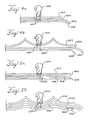
- FIGS. 5 a and 5 bdepict embodiments in which structural plastic layer 502 is mounted nearest the lamp, backed by reflective layer 504 , and with the rear-most layers providing appropriate electrical conductors and insulators.
- plastic or reinforced plastic substrate 502mounts lamp 500 .
- the plasticis desirably a translucent, optically clear, non-pigmented plastic, such as polycarbonate.
- a reflective layer 504is underneath plastic layer 502 , for reflecting light from lamp or LED 500 .
- the reflective layer 504is made of a conductive material, such as polished aluminum. It is also possible that since the material is conductive, it may be used to conduct electricity, such as electric power to the lamp, or a return or ground from the lamp to an external contact.
- FIG. 5 aplastic or reinforced plastic substrate 502 mounts lamp 500 .
- the plasticis desirably a translucent, optically clear, non-pigmented plastic, such as polycarbonate.
- a reflective layer 504is underneath plastic layer 502 , for reflecting light from lamp
- one contact 512 from lamp 500is shown connecting to layer 504 as either an source or a return of electric power.
- the next layer 506may be an insulating layer, such as a thin layer of Kapton® or Nomex® insulation.
- Layer 508may be a conductive layer, such as a copper foil, etched to leave conductors or traces as desired.
- Lamp 500is depicted as having a contact 512 receiving electric power from a trace in layer 508 .
- the last layer 510is desirably another layer of insulating material, and may be a thin layer or alternatively may be a thick layer, such as a back surface of a housing of the light assembly.
- a layer of copperis bonded to insulating layer 510 and is etched to leave traces as conductive layer 508 .
- An insulating layer 506is bonded or overlaid on the conductive layer 508 , as is overlaid by reflective layer 504 .
- This assemblymay then be used as in insert for when plastic substrate 502 is molded, as in an injection-molding or compression molding process. Alternatively, the assembly may be made by hand or by other methods.
- the layersmay be bonded to each other with adhesives or film adhesives, and the film adhesives may function as an insulating layer, such as layer 506 .
- FIG. 5 bdepicts an embodiment in which at least the top layer 522 is formed to enhance the reflectivity of the lamp 520 , i.e. with a bright, shiny, reflective surface.
- the construction of the composite layer structure in FIG. 5 bmay proceed as described for FIG. 5 a , where it is understood that the curved surface is a three-dimensional conical or ellipsoid shape.
- Top layer 522is desirably a structural, translucent, optically clear electrically-insulating plastic, underlaid by a reflective, conductive material 524 .
- Layer 524provides a positive power supply or return for lamp 520 through contact 532 in layer 524 .
- layer 524may be a ground plane or a positive voltage supply.
- Insulating layer 526underlays conductive layer 524 and is followed by second conductive layer 528 .
- Layer 528may be a copper foil or copper plate that is etched to provide traces where desired, to provide electrical power or return to lamp 520 through lamp contact 532 .
- the bottom layeris insulating layer 530 .
- FIG. 6is a view of a back of a substrate in the integrated light assembly.
- the substrate 600is desirably made from one of the plastic or insulating materials mentioned above.
- the substrateis molded or bonded onto a copper foil or conductive layer.
- the conductive layeris then etched, leaving the traces 604 , 624 , 626 , and also traces 612 , 622 .
- the width of the tracesmay be determined by electrical design, e.g., for current carrying capacity or desired voltage drop.
- the tracesmay also extend out of the plane of the substrate for direct connections, as shown in FIG. 2 by conductors 230 , 232 . Such out-of-plane conductors are indicated in each of the figures by small dots at the end of a trace.
- conductors 606are electrical connections to the traces 604 .
- Conductors 606may be traces that have been bent out of the plane of the substrate, connected to module 602 .
- Module 602is mounted to the substrate 600 , and receives power from conductors 606 through traces 604 .
- Module 602may be any of the functional modules mentioned above, such as a tollway transponder or an antenna.
- FIGS. 6-10depict the rear of the substrate, with traces connecting command/communications and external power to various modules and features of the rear of the substrate.
- the actual functions, such as headlights, flashers, antennae, sensors, etc.may be mounted on the front of the substrate and are thus are not depicted on the rear of the substrate.
- FIG. 6also depicts lighting control modules 610 , 620 , mounted to the substrate 600 and connected by traces 624 , 626 , 628 to conductors 630 .
- conductors 630 , 606may be further gathered into a connector (not shown) at the rear of a housing (not shown), which encloses all the above components and may then be connected through a wiring harness to a vehicle controller and source of electric power.
- Lighting control module 610may be a driver or a power source or controller for a low beam lamp (not shown) on the other side of the substrate 600 .
- Two conductors 612connect the module 610 to the low-beam lamp, the abrupt ending of the conductors suggesting a right-angle turn into or out of the substrate.
- module 620may be a controller or power source for a high beam lamp (not shown) on the other side of the substrate 600 , connected by traces or conductors 622 .
- FIG. 7depicts another embodiment of a substrate 700 with numerous modules and traces mounted thereon.
- Control module 704mounts onto the substrate 700 and receives only three inputs from the vehicle control through conductors/traces 702 . These three inputs may be a communication/command circuit, positive power, and ground or negative power.
- Control module 704may include a microprocessor controller or other control device, and may also include a printed circuit board with other components and functions. These functions may include one or more memories, a battery or capacitor for storing electrical energy, and other functions.
- Control module 704is connected to other modules or controllers 708 , 710 , 714 and 718 by traces 706 .
- module 708is a mechanical connector for an antenna (not shown) mounted on the opposite side of substrate 700 .
- Module 710may be a control module for a high-beam headlight, supplying power via traces 712
- module 714may be a control module for a low-beam headlight, supplying power via traces 716 .
- Module 718may be a functional module of one of the functionalities mentioned above, such as a power storage module or an active or passive external automotive function.
- module 718is a battery or capacitor that stores power and allows operation of one or more of the lamps when the auto battery is dead, or during emergency situations.
- FIG. 8is another embodiment depicting the rear of the substrate 800 , with control module 804 mounted on the substrate 800 and connected external power/control by conductors 802 .
- the controls and the power supplies for headlightsare contained within the control module.
- Power to the low beam lampis supplied through traces 806 to connectors 808
- power for the high beam lampis supplied through traces 806 to connectors 810 .
- traces 806also connect power and control to module 812 , which controls an emergency flasher (not shown) through traces 814 .
- the embodimentalso includes battery 816 and radar detector module 818 , both connected to sources of power and control by one or more traces 806 . While two traces are shown for convenience, it is understood that the embodiment is meant to include as many traces or conductive paths as necessary for the functioning of any given module.
- FIG. 9depicts an embodiment with a number of functions.
- Control module 904mounts to substrate 900 .
- Module 904is connected to external control, command and power via conductors 902 .
- Battery 908connects to the control module through traces 906 , as does battery charger 910 .
- Battery charger 910receives power from the control module and charges battery 908 for readiness in emergency situations.
- the battery-charging functionmay be a simple DC-to-DC function, taking power from the automotive battery while the vehicle is operating; or it may be more sophisticated, such as utilizing power only from a regenerative braking operation or recharging of the vehicle battery.
- FIG. 9also depicts low-beam control module 912 , connected to the control module 904 via traces 906 and supplying power through conductors 914 to a low beam lamp (not shown).
- Hi-beam control module 916receives commands and power through traces 906 and supplies power to a high beam lamp (not shown) through conductors 918 .
- Flasher module 920similarly receives commands and power through traces 906 and supplies power to an emergency flasher (not shown) via conductors 922 .
- This embodimentalso includes an active radar transmitter/receiver module 924 , receiving power through traces 906 and relaying information back to the control module 904 , such as information concerning obstacles or objects a motorist should avoid. Such information could be part of a collision-avoidance system, or could be used to alert an operator of the vehicle.
- FIG. 10depicts yet another embodiment, with a number of modules mounted to the substrate 1000 .
- command/control module 1004connected by traces 1002 to external power and command/communication.
- the command module 1004supplies all power and controls for traces leading to a hazard-warning leads 1008 , traces leading to low-beam lamp leads 1010 , and traces to high-beam lamp leads 1012 .
- Functional modules mounted to substrate 1000may also include a battery or storage medium 1014 and a battery charger 1016 .
- Other modules and functionsmay include a sensor 1018 and a radar transmitter or detector 1020 .
- FIG. 11is an isometric front view of an embodiment of an integrated light assembly 1100 .
- the assemblyincludes an insulative plastic structural layer 1102 , and is bonded to reflector-shaped areas 1104 , 1108 .
- the reflector layersmay be made of a reflective material, such as polished aluminum and the layers may be coextensive with and overlay structural plastic layer 1102 .
- Aperturesmay be provided for mounting illumination lamps 1106 , 1110 in the reflective-shaped areas 1104 , 1008 .
- additional functional modulessuch as radar detector 1112 , antenna 1114 , and tollway transponder interface 1116 .
- FIG. 12depicts a top view of another embodiment of an integrated light assembly 1200 .
- the components depictedare housed in housing 1202 , whose front portion may be a translucent, clear plastic, for a head-light type assembly, or may be of a colored plastic, such as red or amber for a rear light or side light or parking light assembly.
- Light assembly 1200includes a laminated composite structure to mount lamps 1216 , 1220 , module 1222 , and control modules 1224 , 1226 .
- top layer 1204is a thin, aluminum foil, forming reflector surfaces 1214 , 1218 for better reflectivity for lamps 1216 , 1220 .
- Reflector layer 1204lies atop structural plastic layer 1206 , which is insulative glass-reinforced polypropylene, about 0.125 inches thick.
- Adhesive layer 1208bonds conductive layer 1210 to the structural plastic layer 1206 .
- Conductive copper layer 1210has been etched to leave conductive traces for electrical connections.
- Insulative layer 1212is a thin layer of adhesive-backed Kapton® insulation, bonding to the conductive layer 1210 and to the structural plastic layer 1206 where the conductive copper layer has been etched.
- Sensor 1222mounts to the reflective layer and the structural plastic layer.
- Modules 1224 and 1226mount to the structural plastic layer also, taking care to insulate any conductive portions so as not to interfere with the electrical aspects of the assembly.
- the traces of layer 1210connect to a male connector 1228 , facilitating the assembly and disassembly of the integrated light assembly onto a motor vehicle.
- FIG. 13depicts another embodiment of an integrated light assembly, this embodiment including a single lamp assembly 1300 which may be used as a side lamp assembly or rear lamp assembly.
- the lamp assemblyhas a housing including a front portion 1302 and a back portion 1303 which are secured together by any convenient means of assembly (not shown), including adhesives, snap-fit features, plastic welding or mechanical fasteners, such as bolts, nuts and screws.
- the front portion 1302is desirably a colored plastic, such as red or amber colors used for taillights or side lights.
- the back portion 1303may be any convenient plastic or material.
- the internal structureis a multi-layered composite structure, including a first clear plastic layer 1304 , followed by a reflective aluminum layer 1306 .
- Lamp 1316may be an LED cluster, or may be an incandescent lamp. Alternatively, if the assembly is an automotive hazardous warning flasher, rather than a side light or parking/running light, the lamp may be a high intensity discharge (HID) lamp.
- HIDhigh intensity discharge
- Layer 1308may be a second plastic structural layer to provide better support under the reflective layer 1306 , and also to insulate the reflective layer 1306 .
- Layer 1310may be a conductive layer, made of flex print or of a conductor that has been etched to leave conductive traces where desired for connection to lamp 1316 and to modules 1318 and 1320 .
- Layer 1312then insulates layer 1310 from modules 1318 and 1320 .
- module 1318is a battery for operating the light assembly remotely when disconnected from the vehicle, while module 1320 is a battery charger for charging the battery.
- Switch 1322enables a user to turn on the light assembly when disconnected from the vehicle and a source of illumination is desired.
- Connector 1324enables convenient connecting and disconnecting of the assembly from a motor vehicle.
- FIG. 14depicts an embodiment 1400 of an interior light and accessory assembly.
- the assembly 1400may fit behind an instrument panel 1402 for back lighting, or may placed in plain view, as for a center dome or rear dome light, or puddle or foot well light assemblies, in a passenger car.
- the assemblymay include a housing 1404 , and a connector 1406 for connection to a harness or other wiring.
- One or more lamps 1408are connected by layers of conductive or insulative material.
- a reflective/conductive layer 1414 as described abovemay overlay an insulative layer 1416 and a second conductive layer 1418 .
- the three layers 1414 - 1416 - 1418are an etched bi-metal material, in which the second conductive layer 1418 is selectively etched to provide conductive paths to lamp terminals 1410 , 1412 , such as a power supply and return.
- the three layersmay also be bonded to a portion of the housing 1404 , insulative layer 1420 , which may be a wall of the housing 1404 .
- a discrete solder-mounted device, a switch, or a plug-in module 1422may control the light assembly, for instance, by timing the maximum or minimum times the light may be light, or by incorporating any of the other properties of sensors or modules mentioned above.
- the methodincludes molding or forming a reflector from a reflective material, such as aluminum, or a metal composite material, such as etched tri-metal, a layered structure having a layer of aluminum between two layers of copper.
- the reflectormay be thick enough to be a structural material for an integrated light assembly, or the metal may be very thin, such as a few thousandths of an inch (0.03.-0.13 mm) of polished, reflective material.
- a thin structure or material for such a structureis formed 1502 .
- Portions of the metalare then masked 1504 and etched away 1506 , in order to form conductors.
- the copper layermay be etched so as to leave traces or conductors on the surface for conducting electricity.
- other materialsmay be used.
- the reflector materialis then placed into a tool 1508 and shaped into place in the tool 1510 .
- a substratesuch as a substrate made from thermoplastic or thermoset molding material, is then molded 1512 around the reflective and conductive materials.
- a thermoplastic materialmay be made using an injection molding process, while a thermoset material may be made using a compression or other molding process.
- insulatorsmay be added to insulate any portions of the conductive layer 1514 . If desired, further conductors or layers of conductors may be added, and then insulated suitably for all-weather, automotive use 1516 . If a circuit board or circuit card assembly is part of the integrated light assembly, it should be added to the light assembly 1518 . Any other modules desired may also be assembled 1520 for the light assembly. The necessary connections or connectors may be added 1522 , and the assembly completed 1524 .
- a layer of metal for electrical connectionsmay be separated by a layer of insulation from the reflective layer.
- any etchingmay not affect the reflective layer, but will have the desired effect on the electrical connections layer, and make electrical connections only where desired.
- a userforms a reflector or reflector material from a reflective metal or from a material having at least one reflective surface 1602 .
- the metalsmay be any suitable metals, especially aluminum, alloys of aluminum, copper, and alloys of copper.
- the materialmay be a layered material, such as two or more layers of metal, or two layers of metal with an insulating layer between. If there is a layer of metal that should be etched to leave only desired conductive traces on one side, a user or manufacturer masks the portions 1604 which the manufacturer wishes to remain, and etches away the other areas of conductor 1606 .
- the reflective portionis then placed into a tool 1608 , the tool being suitable for adhering a substrate to the reflector 1610 .
- a usermay make any desired electrical connections 1612 for the lamps that will be mounted so that their light-emitting portions face the reflective portions of the adhered assembly, and their electrical connecting portions will face the opposite direction. Any necessary insulating may then be accomplished 1614 . If a user desires to add additional conductors, they may be added, along with any layers or insulation desired 1616 . Modules or other components should have been assembled previously 1618 , and may into now be added 1620 to the integrated light assembly. Any other connections desired may then be made 1622 , and the assembly completed 1624 for an automotive or vehicular assembly line.
Landscapes
- Engineering & Computer Science (AREA)
- General Engineering & Computer Science (AREA)
- Microelectronics & Electronic Packaging (AREA)
- Manufacturing & Machinery (AREA)
- Mechanical Engineering (AREA)
- Physics & Mathematics (AREA)
- Optics & Photonics (AREA)
- Arrangement Of Elements, Cooling, Sealing, Or The Like Of Lighting Devices (AREA)
- Lighting Device Outwards From Vehicle And Optical Signal (AREA)
- Non-Portable Lighting Devices Or Systems Thereof (AREA)
Abstract
Description
Claims (22)
Priority Applications (3)
| Application Number | Priority Date | Filing Date | Title |
|---|---|---|---|
| US09/966,634US7048423B2 (en) | 2001-09-28 | 2001-09-28 | Integrated light and accessory assembly |
| DE60206344TDE60206344T2 (en) | 2001-09-28 | 2002-04-23 | Assembly of lights and accessories |
| EP02252859AEP1298007B1 (en) | 2001-09-28 | 2002-04-23 | Integrated light and accessory assembly |
Applications Claiming Priority (1)
| Application Number | Priority Date | Filing Date | Title |
|---|---|---|---|
| US09/966,634US7048423B2 (en) | 2001-09-28 | 2001-09-28 | Integrated light and accessory assembly |
Publications (2)
| Publication Number | Publication Date |
|---|---|
| US20030063477A1 US20030063477A1 (en) | 2003-04-03 |
| US7048423B2true US7048423B2 (en) | 2006-05-23 |
Family
ID=25511673
Family Applications (1)
| Application Number | Title | Priority Date | Filing Date |
|---|---|---|---|
| US09/966,634Expired - LifetimeUS7048423B2 (en) | 2001-09-28 | 2001-09-28 | Integrated light and accessory assembly |
Country Status (3)
| Country | Link |
|---|---|
| US (1) | US7048423B2 (en) |
| EP (1) | EP1298007B1 (en) |
| DE (1) | DE60206344T2 (en) |
Cited By (53)
| Publication number | Priority date | Publication date | Assignee | Title |
|---|---|---|---|---|
| US20030177382A1 (en)* | 2002-03-16 | 2003-09-18 | Yoram Ofek | Trusted flow and operation control method |
| US20050099067A1 (en)* | 2003-11-06 | 2005-05-12 | Fujitsu Ten Limited | Light control apparatus for vehicle |
| US20060056203A1 (en)* | 2004-09-10 | 2006-03-16 | Taiwan Oasis Technology Co., Ltd. | LED luminance enhancing construction |
| US20080062711A1 (en)* | 2006-08-21 | 2008-03-13 | Veenstra Thomas J | Electrical device having boardless electrical component mounting arrangement |
| US20080122241A1 (en)* | 2006-11-02 | 2008-05-29 | Kathleen Blackmore | Ambient lighting for vehicle interior floor console |
| US20080238636A1 (en)* | 2007-04-02 | 2008-10-02 | Torbjorn Birging | Vehicle surveillance and communication system |
| US20080253140A1 (en)* | 2007-03-19 | 2008-10-16 | Fleischmann Eric L | Light for vehicles |
| US20100014308A1 (en)* | 2008-07-15 | 2010-01-21 | Triplex Manufacturing Company | Lighting apparatus and method of manufacture |
| US20100186214A1 (en)* | 2007-03-19 | 2010-07-29 | Judge Michael K | Light for vehicles |
| US7926975B2 (en) | 2007-12-21 | 2011-04-19 | Altair Engineering, Inc. | Light distribution using a light emitting diode assembly |
| US20110096166A1 (en)* | 2009-09-22 | 2011-04-28 | Benjamin Englander | Tractor trailer camera control system and methods of use |
| US7938562B2 (en) | 2008-10-24 | 2011-05-10 | Altair Engineering, Inc. | Lighting including integral communication apparatus |
| US7946729B2 (en) | 2008-07-31 | 2011-05-24 | Altair Engineering, Inc. | Fluorescent tube replacement having longitudinally oriented LEDs |
| US7976196B2 (en) | 2008-07-09 | 2011-07-12 | Altair Engineering, Inc. | Method of forming LED-based light and resulting LED-based light |
| US8118447B2 (en) | 2007-12-20 | 2012-02-21 | Altair Engineering, Inc. | LED lighting apparatus with swivel connection |
| US8214084B2 (en) | 2008-10-24 | 2012-07-03 | Ilumisys, Inc. | Integration of LED lighting with building controls |
| US8256924B2 (en) | 2008-09-15 | 2012-09-04 | Ilumisys, Inc. | LED-based light having rapidly oscillating LEDs |
| US8299695B2 (en) | 2009-06-02 | 2012-10-30 | Ilumisys, Inc. | Screw-in LED bulb comprising a base having outwardly projecting nodes |
| US8324817B2 (en) | 2008-10-24 | 2012-12-04 | Ilumisys, Inc. | Light and light sensor |
| US8330381B2 (en) | 2009-05-14 | 2012-12-11 | Ilumisys, Inc. | Electronic circuit for DC conversion of fluorescent lighting ballast |
| US8362710B2 (en) | 2009-01-21 | 2013-01-29 | Ilumisys, Inc. | Direct AC-to-DC converter for passive component minimization and universal operation of LED arrays |
| US8360599B2 (en) | 2008-05-23 | 2013-01-29 | Ilumisys, Inc. | Electric shock resistant L.E.D. based light |
| US8421366B2 (en) | 2009-06-23 | 2013-04-16 | Ilumisys, Inc. | Illumination device including LEDs and a switching power control system |
| US8444292B2 (en) | 2008-10-24 | 2013-05-21 | Ilumisys, Inc. | End cap substitute for LED-based tube replacement light |
| US8454193B2 (en) | 2010-07-08 | 2013-06-04 | Ilumisys, Inc. | Independent modules for LED fluorescent light tube replacement |
| US8523394B2 (en) | 2010-10-29 | 2013-09-03 | Ilumisys, Inc. | Mechanisms for reducing risk of shock during installation of light tube |
| US8540401B2 (en) | 2010-03-26 | 2013-09-24 | Ilumisys, Inc. | LED bulb with internal heat dissipating structures |
| US8541958B2 (en) | 2010-03-26 | 2013-09-24 | Ilumisys, Inc. | LED light with thermoelectric generator |
| US8556452B2 (en) | 2009-01-15 | 2013-10-15 | Ilumisys, Inc. | LED lens |
| US8596813B2 (en) | 2010-07-12 | 2013-12-03 | Ilumisys, Inc. | Circuit board mount for LED light tube |
| US8653984B2 (en) | 2008-10-24 | 2014-02-18 | Ilumisys, Inc. | Integration of LED lighting control with emergency notification systems |
| US8664880B2 (en) | 2009-01-21 | 2014-03-04 | Ilumisys, Inc. | Ballast/line detection circuit for fluorescent replacement lamps |
| US8674626B2 (en) | 2008-09-02 | 2014-03-18 | Ilumisys, Inc. | LED lamp failure alerting system |
| US8870415B2 (en) | 2010-12-09 | 2014-10-28 | Ilumisys, Inc. | LED fluorescent tube replacement light with reduced shock hazard |
| US8901823B2 (en) | 2008-10-24 | 2014-12-02 | Ilumisys, Inc. | Light and light sensor |
| US9022631B2 (en) | 2012-06-13 | 2015-05-05 | Innotec Corp. | Flexible light pipe |
| US9057493B2 (en) | 2010-03-26 | 2015-06-16 | Ilumisys, Inc. | LED light tube with dual sided light distribution |
| US9072171B2 (en) | 2011-08-24 | 2015-06-30 | Ilumisys, Inc. | Circuit board mount for LED light |
| US9163794B2 (en) | 2012-07-06 | 2015-10-20 | Ilumisys, Inc. | Power supply assembly for LED-based light tube |
| US9184518B2 (en) | 2012-03-02 | 2015-11-10 | Ilumisys, Inc. | Electrical connector header for an LED-based light |
| US9235937B1 (en) | 2013-06-05 | 2016-01-12 | Analog Devices, Inc. | Mounting method for satellite crash sensors |
| US9267650B2 (en) | 2013-10-09 | 2016-02-23 | Ilumisys, Inc. | Lens for an LED-based light |
| US9271367B2 (en) | 2012-07-09 | 2016-02-23 | Ilumisys, Inc. | System and method for controlling operation of an LED-based light |
| US9285084B2 (en) | 2013-03-14 | 2016-03-15 | Ilumisys, Inc. | Diffusers for LED-based lights |
| US9510400B2 (en) | 2014-05-13 | 2016-11-29 | Ilumisys, Inc. | User input systems for an LED-based light |
| US9574717B2 (en) | 2014-01-22 | 2017-02-21 | Ilumisys, Inc. | LED-based light with addressed LEDs |
| WO2017042697A1 (en) | 2015-09-07 | 2017-03-16 | Sabic Global Technologies B.V. | Aerodynamic features of plastic glazing of tailgates |
| WO2017042703A1 (en) | 2015-09-07 | 2017-03-16 | Sabic Global Technologies B.V. | Lighting systems of tailgates with plastic glazing |
| WO2017042699A1 (en) | 2015-09-07 | 2017-03-16 | Sabic Global Technologies B.V. | Molding of plastic glazing of tailgates |
| WO2017042698A1 (en) | 2015-09-07 | 2017-03-16 | Sabic Global Technologies B.V. | Surfaces of plastic glazing of tailgates |
| WO2017089946A2 (en) | 2015-11-23 | 2017-06-01 | Sabic Global Technologies B.V. | Lighting systems for windows having plastic glazing |
| US10161568B2 (en) | 2015-06-01 | 2018-12-25 | Ilumisys, Inc. | LED-based light with canted outer walls |
| US10288249B2 (en) | 2017-07-26 | 2019-05-14 | Ford Global Technologies, Llc | Pattern styling for reducing glare in vehicle lighting assemblies |
Families Citing this family (26)
| Publication number | Priority date | Publication date | Assignee | Title |
|---|---|---|---|---|
| US6825420B2 (en)* | 2002-01-12 | 2004-11-30 | Schefenacker Vision Systems Germany Gmbh & Co. Kg | Conductor of flexible material, component comprising such flexible conductor, and method of manufacturing such conductor |
| US6856883B2 (en)* | 2002-03-06 | 2005-02-15 | Chadwick Ray Traylor | Solid-state accelerometer module and system therefor |
| USD503004S1 (en) | 2003-09-03 | 2005-03-15 | North American Lighting, Inc. | Vehicle fog lamp |
| US7186015B2 (en)* | 2004-04-16 | 2007-03-06 | Polymore Circuit Technologies, Inc. | Backlight display system |
| US7265306B2 (en) | 2004-09-15 | 2007-09-04 | Bodgan Radu | Flip pack switch assembly with electroluminescent lamp and injection molding method of making same |
| US7299892B2 (en) | 2004-09-20 | 2007-11-27 | International Automotive Components Group North America, Inc. | Door trim speaker grille with electroluminescent lamp and injection molding method of making same |
| US7237933B2 (en) | 2004-09-20 | 2007-07-03 | Lear Corporation | Door trim bolster with electroluminescent lamp and injection molding method of making same |
| US7287885B2 (en) | 2004-09-21 | 2007-10-30 | International Automotive Components Group, Llc | Automotive storage compartment having an electroluminescent lamp and method of making the same |
| DE102005045999A1 (en)* | 2004-09-28 | 2006-07-13 | Continental Teves Ag & Co. Ohg | Motor vehicle with lateral environment sensor |
| US7150550B2 (en) | 2004-09-29 | 2006-12-19 | Lear Corporation | Automotive map pocket having an electroluminescent lamp and method of making the same |
| DE102004060890A1 (en) | 2004-12-17 | 2006-06-29 | Patent-Treuhand-Gesellschaft für elektrische Glühlampen mbH | Motor vehicle headlight element |
| US7370995B2 (en)* | 2006-05-04 | 2008-05-13 | International Automotive Components Group North America, Inc. | Console and light assembly |
| SE531043C2 (en)* | 2007-04-02 | 2008-11-25 | Datachassi Dc Ab | Method of monitoring vehicles |
| WO2009091308A1 (en)* | 2008-01-17 | 2009-07-23 | Datachassi Dc Ab | Rf-controllable vehicle side-light unit and method for providing a vehicle with a vehicle lightning system |
| EP2156985A1 (en) | 2008-08-14 | 2010-02-24 | Delphi Technologies, Inc. | Lighting unit for an interior light of a motor vehicle |
| RU2555376C2 (en)* | 2011-12-29 | 2015-07-10 | Федеральное государственное военное образовательное учреждение высшего профессионального образования "Военный учебно-научный центр Сухопутных войск Общевойсковая академия Вооруженных сил Российской Федерации | Device for automatic switching of lighting modes |
| US9557026B2 (en)* | 2012-05-29 | 2017-01-31 | Ichikoh Industries, Ltd. | Vehicular lighting instrument semiconductor light source light source unit and vehicular lighting instrument |
| CN102837636A (en)* | 2012-09-25 | 2012-12-26 | 南京理工大学常熟研究院有限公司 | Car light control device |
| JP2014204029A (en)* | 2013-04-08 | 2014-10-27 | 立山科学工業株式会社 | Led mounting substrate |
| NL2010694C2 (en)* | 2013-04-23 | 2014-10-27 | Cur Dubios B V | APPROACH-DETECTION DEVICE FOR A CARGO VEHICLE. |
| TWI563219B (en)* | 2013-10-28 | 2016-12-21 | Epistar Corp | Illumination system having semiconductor light source module |
| DE102016207823A1 (en)* | 2016-05-06 | 2017-11-09 | Osram Gmbh | Headlamp with circuitry for simulating a load current from a vehicle electrical system |
| US9984567B2 (en)* | 2016-09-09 | 2018-05-29 | Ford Global Technologies, Llc | Detection of oncoming vehicles with IR light |
| KR102550415B1 (en)* | 2018-05-09 | 2023-07-05 | 삼성전자주식회사 | Led device and led lamp using the same |
| EP4336974A1 (en)* | 2022-09-07 | 2024-03-13 | Valeo Vision | Electronic substrate and automotive lighting device for an automotive vehicle |
| EP4336973A1 (en)* | 2022-09-07 | 2024-03-13 | Valeo Vision | Electronic substrate and automotive lighting device for an automotive vehicle |
Citations (43)
| Publication number | Priority date | Publication date | Assignee | Title |
|---|---|---|---|---|
| US4471414A (en) | 1982-03-11 | 1984-09-11 | Savage John Jun | Integrated light unit and circuit element attachable to circuit board |
| US4600977A (en) | 1983-09-14 | 1986-07-15 | Reinhold Barlian | Surveillance signal apparatus |
| US4683517A (en) | 1986-09-15 | 1987-07-28 | General Electric Company | Integrated lighting panelboard and wiring gutter assembly |
| US4812814A (en) | 1988-07-21 | 1989-03-14 | Magnadyne Corporation | Indicating light |
| US4970630A (en) | 1989-06-30 | 1990-11-13 | Gruhn Usa, Inc. | Removably-mountable integral lighting system |
| US5017833A (en) | 1988-04-13 | 1991-05-21 | Square D Company | Pilot light assembly |
| US5213413A (en) | 1992-01-23 | 1993-05-25 | Monte Weathers | Combined light and light support bracket |
| US5349172A (en) | 1992-02-27 | 1994-09-20 | Alex Roustaei | Optical scanning head |
| US5378158A (en) | 1994-01-21 | 1995-01-03 | Delco Electronics Corporation | Light emitting diode and socket assembly |
| JPH07142820A (en)* | 1993-11-22 | 1995-06-02 | Meiko:Kk | Led display board |
| US5444604A (en) | 1994-03-21 | 1995-08-22 | Dme Corporation | Lamp assembly for an evacuation slide |
| US5455749A (en) | 1993-05-28 | 1995-10-03 | Ferber; Andrew R. | Light, audio and current related assemblies, attachments and devices with conductive compositions |
| US5490048A (en) | 1992-11-02 | 1996-02-06 | Valeo Vision | Modular element for motor vehicle indicator lights |
| EP0735799A2 (en) | 1995-03-29 | 1996-10-02 | Intermacom A.G. | Lamp for use with rapid start metal halide bulbs |
| US5580156A (en)* | 1994-09-27 | 1996-12-03 | Koito Manufacturing Co., Ltd. | Marker apparatus |
| US5669698A (en) | 1995-05-24 | 1997-09-23 | Veldman; Roger L. | Modular rearview mirror assembly and method for making same |
| US5746497A (en) | 1995-06-09 | 1998-05-05 | Koito Manufacturing Co., Ltd. | Automotive signal lamps |
| US5765940A (en) | 1995-10-31 | 1998-06-16 | Dialight Corporation | LED-illuminated stop/tail lamp assembly |
| US5782552A (en) | 1995-07-26 | 1998-07-21 | Green; David R. | Light assembly |
| US5797672A (en) | 1995-03-09 | 1998-08-25 | Dobert; Frank C. | Safety light |
| US5865531A (en) | 1995-10-25 | 1999-02-02 | Robert Bosch Gmbh | Headlight for vehicle |
| US5879073A (en) | 1996-01-29 | 1999-03-09 | Koito Manufacturing Co., Ltd. | Vehicular lamp having discharge bulb |
| USD410427S (en) | 1997-07-07 | 1999-06-01 | Kokones Nicholas G | Truck tailgate fairing |
| DE19801587A1 (en) | 1998-01-19 | 1999-07-22 | Patent Treuhand Ges Fuer Elektrische Gluehlampen Mbh | Electric light e.g. as a brake or interior light for a motor vehicle |
| US5938310A (en) | 1997-06-17 | 1999-08-17 | The Whitaker Corporation | Multiple lens component |
| USD413099S (en) | 1997-11-07 | 1999-08-24 | Allen-Bradley Company, Llc | Modular connector |
| US5982059A (en) | 1997-02-07 | 1999-11-09 | Anderson; Marty J. | Electric generator and lighting assembly |
| US6016038A (en) | 1997-08-26 | 2000-01-18 | Color Kinetics, Inc. | Multicolored LED lighting method and apparatus |
| US6015313A (en) | 1997-06-17 | 2000-01-18 | The Whitaker Corporation | Lamp assembly |
| US6033087A (en) | 1996-12-26 | 2000-03-07 | Patlite Corporation | LED illuminating device for providing a uniform light spot |
| US6076950A (en) | 1998-10-05 | 2000-06-20 | Ford Global Technologies, Inc. | Integrated lighting assembly |
| US6079858A (en)* | 1998-08-17 | 2000-06-27 | Lear Automotive Dearborn, Inc. | Side view mirror with detachable flashlight |
| US6095867A (en) | 1998-09-21 | 2000-08-01 | Rockwell Technologies, Llc | Method and apparatus for transmitting power and data signals via a network connector system including integral power capacitors |
| US6113422A (en) | 1994-11-30 | 2000-09-05 | Berg Technology, Inc. | Connector with circuit devices and indicators |
| US6124886A (en)* | 1997-08-25 | 2000-09-26 | Donnelly Corporation | Modular rearview mirror assembly |
| US6139174A (en) | 1998-08-25 | 2000-10-31 | Hewlett-Packard Company | Light source assembly for scanning devices utilizing light emitting diodes |
| US6149288A (en) | 1999-07-27 | 2000-11-21 | Grand General Accessories Manufacturing Inc. | Vehicle light assembly with detachable and replaceable circuit board having plug-in terminal connectors |
| US6152590A (en) | 1998-02-13 | 2000-11-28 | Donnelly Hohe Gmbh & Co. Kg | Lighting device for motor vehicles |
| US6161910A (en) | 1999-12-14 | 2000-12-19 | Aerospace Lighting Corporation | LED reading light |
| US6168725B1 (en) | 1997-12-22 | 2001-01-02 | Visteon Global Technologies, Inc. | Etching of Al-Cu layers to form electronic circuits using base solutions including nitrites, borates or bromates |
| US6179644B1 (en) | 1997-11-07 | 2001-01-30 | Rockwell Technologies, Llc | Power and data network system media architecture |
| US6367949B1 (en)* | 1999-08-04 | 2002-04-09 | 911 Emergency Products, Inc. | Par 36 LED utility lamp |
| US6400308B1 (en)* | 1998-02-20 | 2002-06-04 | Amerigon Inc. | High performance vehicle radar system |
Family Cites Families (11)
| Publication number | Priority date | Publication date | Assignee | Title |
|---|---|---|---|---|
| US4024627A (en)* | 1974-04-29 | 1977-05-24 | Amp Incorporated | Package mounting of electronic chips, such as light emitting diodes |
| US4241277A (en)* | 1979-03-01 | 1980-12-23 | Amp Incorporated | LED Display panel having bus conductors on flexible support |
| DE3587772T2 (en)* | 1984-11-12 | 1994-07-07 | Takiron Co | Dot matrix light display. |
| US4603496A (en)* | 1985-02-04 | 1986-08-05 | Adaptive Micro Systems, Inc. | Electronic display with lens matrix |
| US4774434A (en)* | 1986-08-13 | 1988-09-27 | Innovative Products, Inc. | Lighted display including led's mounted on a flexible circuit board |
| US4935665A (en)* | 1987-12-24 | 1990-06-19 | Mitsubishi Cable Industries Ltd. | Light emitting diode lamp |
| US5024722A (en)* | 1990-06-12 | 1991-06-18 | Micron Technology, Inc. | Process for fabricating conductors used for integrated circuit connections and the like |
| US6441943B1 (en)* | 1997-04-02 | 2002-08-27 | Gentex Corporation | Indicators and illuminators using a semiconductor radiation emitter package |
| TW408497B (en)* | 1997-11-25 | 2000-10-11 | Matsushita Electric Works Ltd | LED illuminating apparatus |
| DE19854803A1 (en)* | 1998-11-27 | 2000-05-31 | Bosch Gmbh Robert | Locally thickened metallic microstructure, for a thermally controlled micro-mirror, is produced using an organic mask layer during metal layer structuring |
| US6468439B1 (en)* | 1999-11-01 | 2002-10-22 | Bmc Industries, Inc. | Etching of metallic composite articles |
- 2001
- 2001-09-28USUS09/966,634patent/US7048423B2/ennot_activeExpired - Lifetime
- 2002
- 2002-04-23DEDE60206344Tpatent/DE60206344T2/ennot_activeExpired - Fee Related
- 2002-04-23EPEP02252859Apatent/EP1298007B1/ennot_activeExpired - Lifetime
Patent Citations (43)
| Publication number | Priority date | Publication date | Assignee | Title |
|---|---|---|---|---|
| US4471414A (en) | 1982-03-11 | 1984-09-11 | Savage John Jun | Integrated light unit and circuit element attachable to circuit board |
| US4600977A (en) | 1983-09-14 | 1986-07-15 | Reinhold Barlian | Surveillance signal apparatus |
| US4683517A (en) | 1986-09-15 | 1987-07-28 | General Electric Company | Integrated lighting panelboard and wiring gutter assembly |
| US5017833A (en) | 1988-04-13 | 1991-05-21 | Square D Company | Pilot light assembly |
| US4812814A (en) | 1988-07-21 | 1989-03-14 | Magnadyne Corporation | Indicating light |
| US4970630A (en) | 1989-06-30 | 1990-11-13 | Gruhn Usa, Inc. | Removably-mountable integral lighting system |
| US5213413A (en) | 1992-01-23 | 1993-05-25 | Monte Weathers | Combined light and light support bracket |
| US5349172A (en) | 1992-02-27 | 1994-09-20 | Alex Roustaei | Optical scanning head |
| US5490048A (en) | 1992-11-02 | 1996-02-06 | Valeo Vision | Modular element for motor vehicle indicator lights |
| US5455749A (en) | 1993-05-28 | 1995-10-03 | Ferber; Andrew R. | Light, audio and current related assemblies, attachments and devices with conductive compositions |
| JPH07142820A (en)* | 1993-11-22 | 1995-06-02 | Meiko:Kk | Led display board |
| US5378158A (en) | 1994-01-21 | 1995-01-03 | Delco Electronics Corporation | Light emitting diode and socket assembly |
| US5444604A (en) | 1994-03-21 | 1995-08-22 | Dme Corporation | Lamp assembly for an evacuation slide |
| US5580156A (en)* | 1994-09-27 | 1996-12-03 | Koito Manufacturing Co., Ltd. | Marker apparatus |
| US6113422A (en) | 1994-11-30 | 2000-09-05 | Berg Technology, Inc. | Connector with circuit devices and indicators |
| US5797672A (en) | 1995-03-09 | 1998-08-25 | Dobert; Frank C. | Safety light |
| EP0735799A2 (en) | 1995-03-29 | 1996-10-02 | Intermacom A.G. | Lamp for use with rapid start metal halide bulbs |
| US5669698A (en) | 1995-05-24 | 1997-09-23 | Veldman; Roger L. | Modular rearview mirror assembly and method for making same |
| US5746497A (en) | 1995-06-09 | 1998-05-05 | Koito Manufacturing Co., Ltd. | Automotive signal lamps |
| US5782552A (en) | 1995-07-26 | 1998-07-21 | Green; David R. | Light assembly |
| US5865531A (en) | 1995-10-25 | 1999-02-02 | Robert Bosch Gmbh | Headlight for vehicle |
| US5765940A (en) | 1995-10-31 | 1998-06-16 | Dialight Corporation | LED-illuminated stop/tail lamp assembly |
| US5879073A (en) | 1996-01-29 | 1999-03-09 | Koito Manufacturing Co., Ltd. | Vehicular lamp having discharge bulb |
| US6033087A (en) | 1996-12-26 | 2000-03-07 | Patlite Corporation | LED illuminating device for providing a uniform light spot |
| US5982059A (en) | 1997-02-07 | 1999-11-09 | Anderson; Marty J. | Electric generator and lighting assembly |
| US5938310A (en) | 1997-06-17 | 1999-08-17 | The Whitaker Corporation | Multiple lens component |
| US6015313A (en) | 1997-06-17 | 2000-01-18 | The Whitaker Corporation | Lamp assembly |
| USD410427S (en) | 1997-07-07 | 1999-06-01 | Kokones Nicholas G | Truck tailgate fairing |
| US6124886A (en)* | 1997-08-25 | 2000-09-26 | Donnelly Corporation | Modular rearview mirror assembly |
| US6016038A (en) | 1997-08-26 | 2000-01-18 | Color Kinetics, Inc. | Multicolored LED lighting method and apparatus |
| US6179644B1 (en) | 1997-11-07 | 2001-01-30 | Rockwell Technologies, Llc | Power and data network system media architecture |
| USD413099S (en) | 1997-11-07 | 1999-08-24 | Allen-Bradley Company, Llc | Modular connector |
| US6168725B1 (en) | 1997-12-22 | 2001-01-02 | Visteon Global Technologies, Inc. | Etching of Al-Cu layers to form electronic circuits using base solutions including nitrites, borates or bromates |
| DE19801587A1 (en) | 1998-01-19 | 1999-07-22 | Patent Treuhand Ges Fuer Elektrische Gluehlampen Mbh | Electric light e.g. as a brake or interior light for a motor vehicle |
| US6152590A (en) | 1998-02-13 | 2000-11-28 | Donnelly Hohe Gmbh & Co. Kg | Lighting device for motor vehicles |
| US6400308B1 (en)* | 1998-02-20 | 2002-06-04 | Amerigon Inc. | High performance vehicle radar system |
| US6079858A (en)* | 1998-08-17 | 2000-06-27 | Lear Automotive Dearborn, Inc. | Side view mirror with detachable flashlight |
| US6139174A (en) | 1998-08-25 | 2000-10-31 | Hewlett-Packard Company | Light source assembly for scanning devices utilizing light emitting diodes |
| US6095867A (en) | 1998-09-21 | 2000-08-01 | Rockwell Technologies, Llc | Method and apparatus for transmitting power and data signals via a network connector system including integral power capacitors |
| US6076950A (en) | 1998-10-05 | 2000-06-20 | Ford Global Technologies, Inc. | Integrated lighting assembly |
| US6149288A (en) | 1999-07-27 | 2000-11-21 | Grand General Accessories Manufacturing Inc. | Vehicle light assembly with detachable and replaceable circuit board having plug-in terminal connectors |
| US6367949B1 (en)* | 1999-08-04 | 2002-04-09 | 911 Emergency Products, Inc. | Par 36 LED utility lamp |
| US6161910A (en) | 1999-12-14 | 2000-12-19 | Aerospace Lighting Corporation | LED reading light |
Non-Patent Citations (1)
| Title |
|---|
| European Search Report May 7, 2004, Ref. P3289.EP/RAM. |
Cited By (104)
| Publication number | Priority date | Publication date | Assignee | Title |
|---|---|---|---|---|
| US20030177382A1 (en)* | 2002-03-16 | 2003-09-18 | Yoram Ofek | Trusted flow and operation control method |
| US7343619B2 (en)* | 2002-03-16 | 2008-03-11 | Trustedflow Systems, Inc. | Trusted flow and operation control method |
| US20050099067A1 (en)* | 2003-11-06 | 2005-05-12 | Fujitsu Ten Limited | Light control apparatus for vehicle |
| US7414328B2 (en)* | 2003-11-06 | 2008-08-19 | Fujitsu Ten Limited | Light control apparatus for vehicle |
| US20060056203A1 (en)* | 2004-09-10 | 2006-03-16 | Taiwan Oasis Technology Co., Ltd. | LED luminance enhancing construction |
| US20080062711A1 (en)* | 2006-08-21 | 2008-03-13 | Veenstra Thomas J | Electrical device having boardless electrical component mounting arrangement |
| US8764240B2 (en) | 2006-08-21 | 2014-07-01 | Innotec Corp. | Electrical device having boardless electrical component mounting arrangement |
| US7909482B2 (en) | 2006-08-21 | 2011-03-22 | Innotec Corporation | Electrical device having boardless electrical component mounting arrangement |
| US7810969B2 (en) | 2006-11-02 | 2010-10-12 | Ford Global Technologies, Llc | Ambient lighting for vehicle interior floor console |
| US20080122241A1 (en)* | 2006-11-02 | 2008-05-29 | Kathleen Blackmore | Ambient lighting for vehicle interior floor console |
| US20080253140A1 (en)* | 2007-03-19 | 2008-10-16 | Fleischmann Eric L | Light for vehicles |
| US7712933B2 (en) | 2007-03-19 | 2010-05-11 | Interlum, Llc | Light for vehicles |
| US20100186214A1 (en)* | 2007-03-19 | 2010-07-29 | Judge Michael K | Light for vehicles |
| US8408773B2 (en) | 2007-03-19 | 2013-04-02 | Innotec Corporation | Light for vehicles |
| US8040226B2 (en) | 2007-04-02 | 2011-10-18 | Datachassi Dc Ab | Vehicle surveillance and communication system |
| US20080238636A1 (en)* | 2007-04-02 | 2008-10-02 | Torbjorn Birging | Vehicle surveillance and communication system |
| US8928025B2 (en) | 2007-12-20 | 2015-01-06 | Ilumisys, Inc. | LED lighting apparatus with swivel connection |
| US8118447B2 (en) | 2007-12-20 | 2012-02-21 | Altair Engineering, Inc. | LED lighting apparatus with swivel connection |
| US7926975B2 (en) | 2007-12-21 | 2011-04-19 | Altair Engineering, Inc. | Light distribution using a light emitting diode assembly |
| US8360599B2 (en) | 2008-05-23 | 2013-01-29 | Ilumisys, Inc. | Electric shock resistant L.E.D. based light |
| US8807785B2 (en) | 2008-05-23 | 2014-08-19 | Ilumisys, Inc. | Electric shock resistant L.E.D. based light |
| US7976196B2 (en) | 2008-07-09 | 2011-07-12 | Altair Engineering, Inc. | Method of forming LED-based light and resulting LED-based light |
| US20100014308A1 (en)* | 2008-07-15 | 2010-01-21 | Triplex Manufacturing Company | Lighting apparatus and method of manufacture |
| US7946729B2 (en) | 2008-07-31 | 2011-05-24 | Altair Engineering, Inc. | Fluorescent tube replacement having longitudinally oriented LEDs |
| US8674626B2 (en) | 2008-09-02 | 2014-03-18 | Ilumisys, Inc. | LED lamp failure alerting system |
| US8256924B2 (en) | 2008-09-15 | 2012-09-04 | Ilumisys, Inc. | LED-based light having rapidly oscillating LEDs |
| US8653984B2 (en) | 2008-10-24 | 2014-02-18 | Ilumisys, Inc. | Integration of LED lighting control with emergency notification systems |
| US7938562B2 (en) | 2008-10-24 | 2011-05-10 | Altair Engineering, Inc. | Lighting including integral communication apparatus |
| US9353939B2 (en) | 2008-10-24 | 2016-05-31 | iLumisys, Inc | Lighting including integral communication apparatus |
| US9398661B2 (en) | 2008-10-24 | 2016-07-19 | Ilumisys, Inc. | Light and light sensor |
| US9585216B2 (en) | 2008-10-24 | 2017-02-28 | Ilumisys, Inc. | Integration of LED lighting with building controls |
| US8444292B2 (en) | 2008-10-24 | 2013-05-21 | Ilumisys, Inc. | End cap substitute for LED-based tube replacement light |
| US11333308B2 (en) | 2008-10-24 | 2022-05-17 | Ilumisys, Inc. | Light and light sensor |
| US11073275B2 (en) | 2008-10-24 | 2021-07-27 | Ilumisys, Inc. | Lighting including integral communication apparatus |
| US10973094B2 (en) | 2008-10-24 | 2021-04-06 | Ilumisys, Inc. | Integration of LED lighting with building controls |
| US10932339B2 (en) | 2008-10-24 | 2021-02-23 | Ilumisys, Inc. | Light and light sensor |
| US9635727B2 (en) | 2008-10-24 | 2017-04-25 | Ilumisys, Inc. | Light and light sensor |
| US10713915B2 (en) | 2008-10-24 | 2020-07-14 | Ilumisys, Inc. | Integration of LED lighting control with emergency notification systems |
| US8324817B2 (en) | 2008-10-24 | 2012-12-04 | Ilumisys, Inc. | Light and light sensor |
| US9101026B2 (en) | 2008-10-24 | 2015-08-04 | Ilumisys, Inc. | Integration of LED lighting with building controls |
| US10036549B2 (en) | 2008-10-24 | 2018-07-31 | Ilumisys, Inc. | Lighting including integral communication apparatus |
| US8214084B2 (en) | 2008-10-24 | 2012-07-03 | Ilumisys, Inc. | Integration of LED lighting with building controls |
| US8251544B2 (en) | 2008-10-24 | 2012-08-28 | Ilumisys, Inc. | Lighting including integral communication apparatus |
| US10571115B2 (en) | 2008-10-24 | 2020-02-25 | Ilumisys, Inc. | Lighting including integral communication apparatus |
| US10560992B2 (en) | 2008-10-24 | 2020-02-11 | Ilumisys, Inc. | Light and light sensor |
| US10342086B2 (en) | 2008-10-24 | 2019-07-02 | Ilumisys, Inc. | Integration of LED lighting with building controls |
| US8901823B2 (en) | 2008-10-24 | 2014-12-02 | Ilumisys, Inc. | Light and light sensor |
| US10176689B2 (en) | 2008-10-24 | 2019-01-08 | Ilumisys, Inc. | Integration of led lighting control with emergency notification systems |
| US8946996B2 (en) | 2008-10-24 | 2015-02-03 | Ilumisys, Inc. | Light and light sensor |
| US10182480B2 (en) | 2008-10-24 | 2019-01-15 | Ilumisys, Inc. | Light and light sensor |
| US8556452B2 (en) | 2009-01-15 | 2013-10-15 | Ilumisys, Inc. | LED lens |
| US8362710B2 (en) | 2009-01-21 | 2013-01-29 | Ilumisys, Inc. | Direct AC-to-DC converter for passive component minimization and universal operation of LED arrays |
| US8664880B2 (en) | 2009-01-21 | 2014-03-04 | Ilumisys, Inc. | Ballast/line detection circuit for fluorescent replacement lamps |
| US8330381B2 (en) | 2009-05-14 | 2012-12-11 | Ilumisys, Inc. | Electronic circuit for DC conversion of fluorescent lighting ballast |
| US8299695B2 (en) | 2009-06-02 | 2012-10-30 | Ilumisys, Inc. | Screw-in LED bulb comprising a base having outwardly projecting nodes |
| US8421366B2 (en) | 2009-06-23 | 2013-04-16 | Ilumisys, Inc. | Illumination device including LEDs and a switching power control system |
| US20110096166A1 (en)* | 2009-09-22 | 2011-04-28 | Benjamin Englander | Tractor trailer camera control system and methods of use |
| US9057493B2 (en) | 2010-03-26 | 2015-06-16 | Ilumisys, Inc. | LED light tube with dual sided light distribution |
| US8840282B2 (en) | 2010-03-26 | 2014-09-23 | Ilumisys, Inc. | LED bulb with internal heat dissipating structures |
| US9013119B2 (en) | 2010-03-26 | 2015-04-21 | Ilumisys, Inc. | LED light with thermoelectric generator |
| US9395075B2 (en) | 2010-03-26 | 2016-07-19 | Ilumisys, Inc. | LED bulb for incandescent bulb replacement with internal heat dissipating structures |
| US8540401B2 (en) | 2010-03-26 | 2013-09-24 | Ilumisys, Inc. | LED bulb with internal heat dissipating structures |
| US8541958B2 (en) | 2010-03-26 | 2013-09-24 | Ilumisys, Inc. | LED light with thermoelectric generator |
| US8454193B2 (en) | 2010-07-08 | 2013-06-04 | Ilumisys, Inc. | Independent modules for LED fluorescent light tube replacement |
| US8596813B2 (en) | 2010-07-12 | 2013-12-03 | Ilumisys, Inc. | Circuit board mount for LED light tube |
| US8894430B2 (en) | 2010-10-29 | 2014-11-25 | Ilumisys, Inc. | Mechanisms for reducing risk of shock during installation of light tube |
| US8523394B2 (en) | 2010-10-29 | 2013-09-03 | Ilumisys, Inc. | Mechanisms for reducing risk of shock during installation of light tube |
| US8870415B2 (en) | 2010-12-09 | 2014-10-28 | Ilumisys, Inc. | LED fluorescent tube replacement light with reduced shock hazard |
| US9072171B2 (en) | 2011-08-24 | 2015-06-30 | Ilumisys, Inc. | Circuit board mount for LED light |
| US9184518B2 (en) | 2012-03-02 | 2015-11-10 | Ilumisys, Inc. | Electrical connector header for an LED-based light |
| US9022631B2 (en) | 2012-06-13 | 2015-05-05 | Innotec Corp. | Flexible light pipe |
| US9163794B2 (en) | 2012-07-06 | 2015-10-20 | Ilumisys, Inc. | Power supply assembly for LED-based light tube |
| US10966295B2 (en) | 2012-07-09 | 2021-03-30 | Ilumisys, Inc. | System and method for controlling operation of an LED-based light |
| US9807842B2 (en) | 2012-07-09 | 2017-10-31 | Ilumisys, Inc. | System and method for controlling operation of an LED-based light |
| US9271367B2 (en) | 2012-07-09 | 2016-02-23 | Ilumisys, Inc. | System and method for controlling operation of an LED-based light |
| US10278247B2 (en) | 2012-07-09 | 2019-04-30 | Ilumisys, Inc. | System and method for controlling operation of an LED-based light |
| US9285084B2 (en) | 2013-03-14 | 2016-03-15 | Ilumisys, Inc. | Diffusers for LED-based lights |
| US9235937B1 (en) | 2013-06-05 | 2016-01-12 | Analog Devices, Inc. | Mounting method for satellite crash sensors |
| US9267650B2 (en) | 2013-10-09 | 2016-02-23 | Ilumisys, Inc. | Lens for an LED-based light |
| US9574717B2 (en) | 2014-01-22 | 2017-02-21 | Ilumisys, Inc. | LED-based light with addressed LEDs |
| US10260686B2 (en) | 2014-01-22 | 2019-04-16 | Ilumisys, Inc. | LED-based light with addressed LEDs |
| US9510400B2 (en) | 2014-05-13 | 2016-11-29 | Ilumisys, Inc. | User input systems for an LED-based light |
| US10690296B2 (en) | 2015-06-01 | 2020-06-23 | Ilumisys, Inc. | LED-based light with canted outer walls |
| US11428370B2 (en) | 2015-06-01 | 2022-08-30 | Ilumisys, Inc. | LED-based light with canted outer walls |
| US10161568B2 (en) | 2015-06-01 | 2018-12-25 | Ilumisys, Inc. | LED-based light with canted outer walls |
| US11028972B2 (en) | 2015-06-01 | 2021-06-08 | Ilumisys, Inc. | LED-based light with canted outer walls |
| WO2017042698A1 (en) | 2015-09-07 | 2017-03-16 | Sabic Global Technologies B.V. | Surfaces of plastic glazing of tailgates |
| US11267173B2 (en) | 2015-09-07 | 2022-03-08 | Sabic Global Technologies B.V. | Molding of plastic glazing of tailgates |
| US10717348B2 (en) | 2015-09-07 | 2020-07-21 | Sabic Global Technologies B.V. | Surfaces of plastic glazing of tailgates |
| US10690314B2 (en) | 2015-09-07 | 2020-06-23 | Sabic Global Technologies B.V. | Lighting systems of tailgates with plastic glazing |
| US10948152B2 (en) | 2015-09-07 | 2021-03-16 | Sabic Global Technologies B.V. | Lighting systems of tailgates with plastic glazing |
| US10597097B2 (en) | 2015-09-07 | 2020-03-24 | Sabic Global Technologies B.V. | Aerodynamic features of plastic glazing of tailgates |
| WO2017042699A1 (en) | 2015-09-07 | 2017-03-16 | Sabic Global Technologies B.V. | Molding of plastic glazing of tailgates |
| WO2017042697A1 (en) | 2015-09-07 | 2017-03-16 | Sabic Global Technologies B.V. | Aerodynamic features of plastic glazing of tailgates |
| US12390967B2 (en) | 2015-09-07 | 2025-08-19 | Sabic Global Technologies B.V. | Molding of plastic glazing of tailgates |
| US12330397B2 (en) | 2015-09-07 | 2025-06-17 | Sabic Global Technologies B.V. | Three shot plastic tailgate |
| WO2017042703A1 (en) | 2015-09-07 | 2017-03-16 | Sabic Global Technologies B.V. | Lighting systems of tailgates with plastic glazing |
| US10434846B2 (en) | 2015-09-07 | 2019-10-08 | Sabic Global Technologies B.V. | Surfaces of plastic glazing of tailgates |
| US11458709B2 (en) | 2015-09-07 | 2022-10-04 | Sabic Global Technologies B.V. | Three shot plastic tailgate |
| US11845240B2 (en) | 2015-09-07 | 2023-12-19 | Sabic Global Technologies B.V. | Three shot plastic tailgate |
| US11466834B2 (en) | 2015-11-23 | 2022-10-11 | Sabic Global Technologies B.V. | Lighting systems for windows having plastic glazing |
| US12145498B2 (en) | 2015-11-23 | 2024-11-19 | Sabic Global Technologies B.V. | Illuminated graphic in an automotive plastic glazing |
| WO2017089946A2 (en) | 2015-11-23 | 2017-06-01 | Sabic Global Technologies B.V. | Lighting systems for windows having plastic glazing |
| US10288249B2 (en) | 2017-07-26 | 2019-05-14 | Ford Global Technologies, Llc | Pattern styling for reducing glare in vehicle lighting assemblies |
Also Published As
| Publication number | Publication date |
|---|---|
| EP1298007A3 (en) | 2004-07-07 |
| DE60206344T2 (en) | 2006-06-22 |
| DE60206344D1 (en) | 2006-02-09 |
| US20030063477A1 (en) | 2003-04-03 |
| EP1298007A2 (en) | 2003-04-02 |
| EP1298007B1 (en) | 2005-09-28 |
Similar Documents
| Publication | Publication Date | Title |
|---|---|---|
| US7048423B2 (en) | Integrated light and accessory assembly | |
| US6520669B1 (en) | Flexible substrate mounted solid-state light sources for exterior vehicular lighting | |
| US6840660B2 (en) | High signal lights for automotive vehicles | |
| US7488099B2 (en) | Rearview mirror light | |
| US9132821B2 (en) | Stop lamp drive apparatus | |
| US7427150B2 (en) | Rearview mirror assembly including a multi-functional light module | |
| US9539932B2 (en) | Light emitting diode lighting system | |
| US20150180178A1 (en) | Fastener Assembly For Use With Vehicle Article Carrier | |
| EP0940293A1 (en) | Motor vehicle warning signal light assembly | |
| WO1998057097A1 (en) | Electroluminescent lamps for vehicle lighting | |
| US6674182B2 (en) | Emergency vehicle wiring harness and control system | |
| US4754838A (en) | Electronic ignition by-pass system | |
| EP1582405A2 (en) | Vehicle indicator using side-emitting light-emitting diode | |
| CN212667252U (en) | Automobile tail lamp system and automobile | |
| US20070081350A1 (en) | Rearview mirror and signal light arrangement | |
| US11264707B2 (en) | Antenna apparatus and related communication systems for use with vehicle lamps | |
| US11067243B2 (en) | Opaque outer lens with integrated light element | |
| CN118025338A (en) | Body panel with integrated functional components | |
| US12036939B2 (en) | Driver airbag module with lighting device, control method, and manufacturing method of same | |
| WO2004024502A2 (en) | Rearview mirror assembly including a multi-functional light module | |
| CN212361917U (en) | Intelligent automobile warning auxiliary lamp | |
| US7242287B1 (en) | Vehicle warning system and method | |
| CN115711371A (en) | Vehicle exterior lighting system with exposable fender lamp assembly | |
| KR101367770B1 (en) | Method of manufacturing pcb unit for light emitting divice | |
| CN219756279U (en) | Multi-power-supply-driven automobile fog lamp assembly |
Legal Events
| Date | Code | Title | Description |
|---|---|---|---|
| AS | Assignment | Owner name:FORD MOTOR CO., MICHIGAN Free format text:ASSIGNMENT OF ASSIGNORS INTEREST;ASSIGNOR:LANGER, PETER;REEL/FRAME:012228/0717 Effective date:20010911 Owner name:VISTEON GLOBAL TECHNOLOGIES, INC., MICHIGAN Free format text:ASSIGNMENT OF ASSIGNORS INTEREST;ASSIGNORS:STEPANENKO, WALTER KUZMA;BAKER, JAY DEAVIS;KNEISEL, LAWRENCE LEROY;AND OTHERS;REEL/FRAME:012228/0725;SIGNING DATES FROM 20010905 TO 20010910 | |
| AS | Assignment | Owner name:VISTEON GLOBAL TECHNOLOGIES, INC., MICHIGAN Free format text:ASSIGNMENT OF ASSIGNORS INTEREST;ASSIGNOR:FORD MOTOR COMPANY (FORD);REEL/FRAME:012728/0413 Effective date:20020301 | |
| STCF | Information on status: patent grant | Free format text:PATENTED CASE | |
| AS | Assignment | Owner name:JPMORGAN CHASE BANK, N.A., AS ADMINISTRATIVE AGENT Free format text:SECURITY AGREEMENT;ASSIGNOR:VISTEON GLOBAL TECHNOLOGIES, INC.;REEL/FRAME:020497/0733 Effective date:20060613 | |
| AS | Assignment | Owner name:JPMORGAN CHASE BANK, TEXAS Free format text:SECURITY INTEREST;ASSIGNOR:VISTEON GLOBAL TECHNOLOGIES, INC.;REEL/FRAME:022368/0001 Effective date:20060814 Owner name:JPMORGAN CHASE BANK,TEXAS Free format text:SECURITY INTEREST;ASSIGNOR:VISTEON GLOBAL TECHNOLOGIES, INC.;REEL/FRAME:022368/0001 Effective date:20060814 | |
| AS | Assignment | Owner name:WILMINGTON TRUST FSB, AS ADMINISTRATIVE AGENT, MIN Free format text:ASSIGNMENT OF SECURITY INTEREST IN PATENTS;ASSIGNOR:JPMORGAN CHASE BANK, N.A., AS ADMINISTRATIVE AGENT;REEL/FRAME:022575/0186 Effective date:20090415 Owner name:WILMINGTON TRUST FSB, AS ADMINISTRATIVE AGENT,MINN Free format text:ASSIGNMENT OF SECURITY INTEREST IN PATENTS;ASSIGNOR:JPMORGAN CHASE BANK, N.A., AS ADMINISTRATIVE AGENT;REEL/FRAME:022575/0186 Effective date:20090415 | |
| AS | Assignment | Owner name:THE BANK OF NEW YORK MELLON, AS ADMINISTRATIVE AGE Free format text:ASSIGNMENT OF PATENT SECURITY INTEREST;ASSIGNOR:JPMORGAN CHASE BANK, N.A., A NATIONAL BANKING ASSOCIATION;REEL/FRAME:022974/0057 Effective date:20090715 | |
| FPAY | Fee payment | Year of fee payment:4 | |
| AS | Assignment | Owner name:VISTEON GLOBAL TECHNOLOGIES, INC., MICHIGAN Free format text:RELEASE BY SECURED PARTY AGAINST SECURITY INTEREST IN PATENTS RECORDED AT REEL 022974 FRAME 0057;ASSIGNOR:THE BANK OF NEW YORK MELLON;REEL/FRAME:025095/0711 Effective date:20101001 | |
| AS | Assignment | Owner name:VISTEON GLOBAL TECHNOLOGIES, INC., MICHIGAN Free format text:RELEASE BY SECURED PARTY AGAINST SECURITY INTEREST IN PATENTS RECORDED AT REEL 022575 FRAME 0186;ASSIGNOR:WILMINGTON TRUST FSB, AS ADMINISTRATIVE AGENT;REEL/FRAME:025105/0201 Effective date:20101001 | |
| AS | Assignment | Owner name:MORGAN STANLEY SENIOR FUNDING, INC., AS AGENT, NEW Free format text:SECURITY AGREEMENT (REVOLVER);ASSIGNORS:VISTEON CORPORATION;VC AVIATION SERVICES, LLC;VISTEON ELECTRONICS CORPORATION;AND OTHERS;REEL/FRAME:025238/0298 Effective date:20101001 Owner name:MORGAN STANLEY SENIOR FUNDING, INC., AS AGENT, NEW Free format text:SECURITY AGREEMENT;ASSIGNORS:VISTEON CORPORATION;VC AVIATION SERVICES, LLC;VISTEON ELECTRONICS CORPORATION;AND OTHERS;REEL/FRAME:025241/0317 Effective date:20101007 | |
| AS | Assignment | Owner name:VISTEON INTERNATIONAL BUSINESS DEVELOPMENT, INC., Free format text:RELEASE BY SECURED PARTY AGAINST SECURITY INTEREST IN PATENTS ON REEL 025241 FRAME 0317;ASSIGNOR:MORGAN STANLEY SENIOR FUNDING, INC.;REEL/FRAME:026178/0412 Effective date:20110406 Owner name:VISTEON GLOBAL TREASURY, INC., MICHIGAN Free format text:RELEASE BY SECURED PARTY AGAINST SECURITY INTEREST IN PATENTS ON REEL 025241 FRAME 0317;ASSIGNOR:MORGAN STANLEY SENIOR FUNDING, INC.;REEL/FRAME:026178/0412 Effective date:20110406 Owner name:VISTEON INTERNATIONAL HOLDINGS, INC., MICHIGAN Free format text:RELEASE BY SECURED PARTY AGAINST SECURITY INTEREST IN PATENTS ON REEL 025241 FRAME 0317;ASSIGNOR:MORGAN STANLEY SENIOR FUNDING, INC.;REEL/FRAME:026178/0412 Effective date:20110406 Owner name:VC AVIATION SERVICES, LLC, MICHIGAN Free format text:RELEASE BY SECURED PARTY AGAINST SECURITY INTEREST IN PATENTS ON REEL 025241 FRAME 0317;ASSIGNOR:MORGAN STANLEY SENIOR FUNDING, INC.;REEL/FRAME:026178/0412 Effective date:20110406 Owner name:VISTEON SYSTEMS, LLC, MICHIGAN Free format text:RELEASE BY SECURED PARTY AGAINST SECURITY INTEREST IN PATENTS ON REEL 025241 FRAME 0317;ASSIGNOR:MORGAN STANLEY SENIOR FUNDING, INC.;REEL/FRAME:026178/0412 Effective date:20110406 Owner name:VISTEON CORPORATION, MICHIGAN Free format text:RELEASE BY SECURED PARTY AGAINST SECURITY INTEREST IN PATENTS ON REEL 025241 FRAME 0317;ASSIGNOR:MORGAN STANLEY SENIOR FUNDING, INC.;REEL/FRAME:026178/0412 Effective date:20110406 Owner name:VISTEON ELECTRONICS CORPORATION, MICHIGAN Free format text:RELEASE BY SECURED PARTY AGAINST SECURITY INTEREST IN PATENTS ON REEL 025241 FRAME 0317;ASSIGNOR:MORGAN STANLEY SENIOR FUNDING, INC.;REEL/FRAME:026178/0412 Effective date:20110406 Owner name:VISTEON GLOBAL TECHNOLOGIES, INC., MICHIGAN Free format text:RELEASE BY SECURED PARTY AGAINST SECURITY INTEREST IN PATENTS ON REEL 025241 FRAME 0317;ASSIGNOR:MORGAN STANLEY SENIOR FUNDING, INC.;REEL/FRAME:026178/0412 Effective date:20110406 Owner name:VISTEON EUROPEAN HOLDING, INC., MICHIGAN Free format text:RELEASE BY SECURED PARTY AGAINST SECURITY INTEREST IN PATENTS ON REEL 025241 FRAME 0317;ASSIGNOR:MORGAN STANLEY SENIOR FUNDING, INC.;REEL/FRAME:026178/0412 Effective date:20110406 | |
| FPAY | Fee payment | Year of fee payment:8 | |
| AS | Assignment | Owner name:CITIBANK., N.A., AS ADMINISTRATIVE AGENT, NEW YORK Free format text:SECURITY INTEREST;ASSIGNORS:VISTEON CORPORATION, AS GRANTOR;VISTEON GLOBAL TECHNOLOGIES, INC., AS GRANTOR;REEL/FRAME:032713/0065 Effective date:20140409 | |
| AS | Assignment | Owner name:VISTEON GLOBAL TECHNOLOGIES, INC., MICHIGAN Free format text:RELEASE OF SECURITY INTEREST IN INTELLECTUAL PROPERTY;ASSIGNOR:MORGAN STANLEY SENIOR FUNDING, INC.;REEL/FRAME:033107/0717 Effective date:20140409 Owner name:VISTEON ELECTRONICS CORPORATION, MICHIGAN Free format text:RELEASE OF SECURITY INTEREST IN INTELLECTUAL PROPERTY;ASSIGNOR:MORGAN STANLEY SENIOR FUNDING, INC.;REEL/FRAME:033107/0717 Effective date:20140409 Owner name:VISTEON INTERNATIONAL HOLDINGS, INC., MICHIGAN Free format text:RELEASE OF SECURITY INTEREST IN INTELLECTUAL PROPERTY;ASSIGNOR:MORGAN STANLEY SENIOR FUNDING, INC.;REEL/FRAME:033107/0717 Effective date:20140409 Owner name:VISTEON SYSTEMS, LLC, MICHIGAN Free format text:RELEASE OF SECURITY INTEREST IN INTELLECTUAL PROPERTY;ASSIGNOR:MORGAN STANLEY SENIOR FUNDING, INC.;REEL/FRAME:033107/0717 Effective date:20140409 Owner name:VISTEON INTERNATIONAL BUSINESS DEVELOPMENT, INC., Free format text:RELEASE OF SECURITY INTEREST IN INTELLECTUAL PROPERTY;ASSIGNOR:MORGAN STANLEY SENIOR FUNDING, INC.;REEL/FRAME:033107/0717 Effective date:20140409 Owner name:VISTEON GLOBAL TREASURY, INC., MICHIGAN Free format text:RELEASE OF SECURITY INTEREST IN INTELLECTUAL PROPERTY;ASSIGNOR:MORGAN STANLEY SENIOR FUNDING, INC.;REEL/FRAME:033107/0717 Effective date:20140409 Owner name:VISTEON CORPORATION, MICHIGAN Free format text:RELEASE OF SECURITY INTEREST IN INTELLECTUAL PROPERTY;ASSIGNOR:MORGAN STANLEY SENIOR FUNDING, INC.;REEL/FRAME:033107/0717 Effective date:20140409 Owner name:VISTEON EUROPEAN HOLDINGS, INC., MICHIGAN Free format text:RELEASE OF SECURITY INTEREST IN INTELLECTUAL PROPERTY;ASSIGNOR:MORGAN STANLEY SENIOR FUNDING, INC.;REEL/FRAME:033107/0717 Effective date:20140409 Owner name:VC AVIATION SERVICES, LLC, MICHIGAN Free format text:RELEASE OF SECURITY INTEREST IN INTELLECTUAL PROPERTY;ASSIGNOR:MORGAN STANLEY SENIOR FUNDING, INC.;REEL/FRAME:033107/0717 Effective date:20140409 | |
| FEPP | Fee payment procedure | Free format text:PAYOR NUMBER ASSIGNED (ORIGINAL EVENT CODE: ASPN); ENTITY STATUS OF PATENT OWNER: LARGE ENTITY | |
| MAFP | Maintenance fee payment | Free format text:PAYMENT OF MAINTENANCE FEE, 12TH YEAR, LARGE ENTITY (ORIGINAL EVENT CODE: M1553) Year of fee payment:12 |