US7047883B2 - Method and apparatus for orienting magnetic flakes - Google Patents
Method and apparatus for orienting magnetic flakesDownload PDFInfo
- Publication number
- US7047883B2 US7047883B2US10/386,894US38689403AUS7047883B2US 7047883 B2US7047883 B2US 7047883B2US 38689403 AUS38689403 AUS 38689403AUS 7047883 B2US7047883 B2US 7047883B2
- Authority
- US
- United States
- Prior art keywords
- magnet
- magnetic
- substrate
- image
- flakes
- Prior art date
- Legal status (The legal status is an assumption and is not a legal conclusion. Google has not performed a legal analysis and makes no representation as to the accuracy of the status listed.)
- Expired - Lifetime, expires
Links
- 238000000034methodMethods0.000titleclaimsabstractdescription44
- 239000000049pigmentSubstances0.000claimsabstractdescription69
- 239000000758substrateSubstances0.000claimsdescription101
- 238000005096rolling processMethods0.000claimsdescription30
- 230000008569processEffects0.000claimsdescription25
- 239000012530fluidSubstances0.000claimsdescription14
- 239000003973paintSubstances0.000abstractdescription28
- 230000003287optical effectEffects0.000abstractdescription22
- 239000000976inkSubstances0.000description24
- 238000010422paintingMethods0.000description11
- 230000007704transitionEffects0.000description11
- 239000000463materialSubstances0.000description10
- 230000000694effectsEffects0.000description9
- 229910001172neodymium magnetInorganic materials0.000description9
- 239000007788liquidSubstances0.000description8
- 230000000712assemblyEffects0.000description7
- 238000000429assemblyMethods0.000description7
- 229910000815supermalloyInorganic materials0.000description7
- 230000000007visual effectEffects0.000description7
- PXHVJJICTQNCMI-UHFFFAOYSA-NNickelChemical compound[Ni]PXHVJJICTQNCMI-UHFFFAOYSA-N0.000description6
- 238000005286illuminationMethods0.000description6
- 230000006872improvementEffects0.000description5
- 239000004033plasticSubstances0.000description5
- 229910045601alloyInorganic materials0.000description4
- 239000000956alloySubstances0.000description4
- 239000010408filmSubstances0.000description4
- 229910052751metalInorganic materials0.000description4
- 239000002184metalSubstances0.000description4
- 239000002904solventSubstances0.000description4
- 238000001723curingMethods0.000description3
- 238000001035dryingMethods0.000description3
- 230000002708enhancing effectEffects0.000description3
- 239000006249magnetic particleSubstances0.000description3
- 229910001092metal group alloyInorganic materials0.000description3
- 239000000123paperSubstances0.000description3
- 239000002985plastic filmSubstances0.000description3
- 229920006255plastic filmPolymers0.000description3
- 229910000990Ni alloyInorganic materials0.000description2
- XAGFODPZIPBFFR-UHFFFAOYSA-NaluminiumChemical compound[Al]XAGFODPZIPBFFR-UHFFFAOYSA-N0.000description2
- 238000013459approachMethods0.000description2
- 230000015572biosynthetic processEffects0.000description2
- 239000000969carrierSubstances0.000description2
- 239000011248coating agentSubstances0.000description2
- 238000000576coating methodMethods0.000description2
- 239000003086colorantSubstances0.000description2
- 239000002650laminated plasticSubstances0.000description2
- 239000000696magnetic materialSubstances0.000description2
- 230000005415magnetizationEffects0.000description2
- 238000004519manufacturing processMethods0.000description2
- 239000000203mixtureSubstances0.000description2
- 238000012986modificationMethods0.000description2
- 230000004048modificationEffects0.000description2
- 230000035699permeabilityEffects0.000description2
- BASFCYQUMIYNBI-UHFFFAOYSA-NplatinumChemical compound[Pt]BASFCYQUMIYNBI-UHFFFAOYSA-N0.000description2
- 239000010409thin filmSubstances0.000description2
- 238000013519translationMethods0.000description2
- 229910000838Al alloyInorganic materials0.000description1
- 229910001020Au alloyInorganic materials0.000description1
- 241000123409Coltricia perennisSpecies0.000description1
- 229910001260Pt alloyInorganic materials0.000description1
- 238000003848UV Light-CuringMethods0.000description1
- QJVKUMXDEUEQLH-UHFFFAOYSA-N[B].[Fe].[Nd]Chemical compound[B].[Fe].[Nd]QJVKUMXDEUEQLH-UHFFFAOYSA-N0.000description1
- 230000006978adaptationEffects0.000description1
- 229910000828alnicoInorganic materials0.000description1
- 229910052782aluminiumInorganic materials0.000description1
- 238000010923batch productionMethods0.000description1
- 230000008901benefitEffects0.000description1
- 230000015556catabolic processEffects0.000description1
- 230000008859changeEffects0.000description1
- KPLQYGBQNPPQGA-UHFFFAOYSA-Ncobalt samariumChemical compound[Co].[Sm]KPLQYGBQNPPQGA-UHFFFAOYSA-N0.000description1
- 238000006731degradation reactionMethods0.000description1
- 238000011161developmentMethods0.000description1
- 239000010432diamondSubstances0.000description1
- 229910003460diamondInorganic materials0.000description1
- 238000001704evaporationMethods0.000description1
- 230000008020evaporationEffects0.000description1
- 239000004811fluoropolymerSubstances0.000description1
- 229920002313fluoropolymerPolymers0.000description1
- 239000011888foilSubstances0.000description1
- 238000009472formulationMethods0.000description1
- 239000010437gemSubstances0.000description1
- 229910001751gemstoneInorganic materials0.000description1
- PCHJSUWPFVWCPO-UHFFFAOYSA-NgoldChemical compound[Au]PCHJSUWPFVWCPO-UHFFFAOYSA-N0.000description1
- 239000010931goldSubstances0.000description1
- 239000011159matrix materialSubstances0.000description1
- 238000005259measurementMethods0.000description1
- 229910000595mu-metalInorganic materials0.000description1
- 229910052759nickelInorganic materials0.000description1
- 238000004806packaging method and processMethods0.000description1
- 239000002245particleSubstances0.000description1
- 229910000889permalloyInorganic materials0.000description1
- 230000010287polarizationEffects0.000description1
- 238000004663powder metallurgyMethods0.000description1
- 230000009467reductionEffects0.000description1
- 238000011160researchMethods0.000description1
- 229910000938samarium–cobalt magnetInorganic materials0.000description1
- 238000012216screeningMethods0.000description1
- 238000000926separation methodMethods0.000description1
- 238000007493shaping processMethods0.000description1
- 125000006850spacer groupChemical group0.000description1
- 239000012798spherical particleSubstances0.000description1
- 230000003068static effectEffects0.000description1
- 238000006467substitution reactionMethods0.000description1
- XLYOFNOQVPJJNP-UHFFFAOYSA-NwaterSubstancesOXLYOFNOQVPJJNP-UHFFFAOYSA-N0.000description1
Images


Classifications
- B—PERFORMING OPERATIONS; TRANSPORTING
- B41—PRINTING; LINING MACHINES; TYPEWRITERS; STAMPS
- B41M—PRINTING, DUPLICATING, MARKING, OR COPYING PROCESSES; COLOUR PRINTING
- B41M1/00—Inking and printing with a printer's forme
- B—PERFORMING OPERATIONS; TRANSPORTING
- B05—SPRAYING OR ATOMISING IN GENERAL; APPLYING FLUENT MATERIALS TO SURFACES, IN GENERAL
- B05D—PROCESSES FOR APPLYING FLUENT MATERIALS TO SURFACES, IN GENERAL
- B05D3/00—Pretreatment of surfaces to which liquids or other fluent materials are to be applied; After-treatment of applied coatings, e.g. intermediate treating of an applied coating preparatory to subsequent applications of liquids or other fluent materials
- B05D3/20—Pretreatment of surfaces to which liquids or other fluent materials are to be applied; After-treatment of applied coatings, e.g. intermediate treating of an applied coating preparatory to subsequent applications of liquids or other fluent materials by magnetic fields
- B05D3/207—Pretreatment of surfaces to which liquids or other fluent materials are to be applied; After-treatment of applied coatings, e.g. intermediate treating of an applied coating preparatory to subsequent applications of liquids or other fluent materials by magnetic fields post-treatment by magnetic fields
- B—PERFORMING OPERATIONS; TRANSPORTING
- B05—SPRAYING OR ATOMISING IN GENERAL; APPLYING FLUENT MATERIALS TO SURFACES, IN GENERAL
- B05D—PROCESSES FOR APPLYING FLUENT MATERIALS TO SURFACES, IN GENERAL
- B05D5/00—Processes for applying liquids or other fluent materials to surfaces to obtain special surface effects, finishes or structures
- B05D5/06—Processes for applying liquids or other fluent materials to surfaces to obtain special surface effects, finishes or structures to obtain multicolour or other optical effects
- B05D5/061—Special surface effect
- B—PERFORMING OPERATIONS; TRANSPORTING
- B41—PRINTING; LINING MACHINES; TYPEWRITERS; STAMPS
- B41F—PRINTING MACHINES OR PRESSES
- B41F11/00—Rotary presses or machines having forme cylinders carrying a plurality of printing surfaces, or for performing letterpress, lithographic, or intaglio processes selectively or in combination
- B41F11/02—Rotary presses or machines having forme cylinders carrying a plurality of printing surfaces, or for performing letterpress, lithographic, or intaglio processes selectively or in combination for securities
- B—PERFORMING OPERATIONS; TRANSPORTING
- B41—PRINTING; LINING MACHINES; TYPEWRITERS; STAMPS
- B41F—PRINTING MACHINES OR PRESSES
- B41F23/00—Devices for treating the surfaces of sheets, webs, or other articles in connection with printing
- B—PERFORMING OPERATIONS; TRANSPORTING
- B41—PRINTING; LINING MACHINES; TYPEWRITERS; STAMPS
- B41M—PRINTING, DUPLICATING, MARKING, OR COPYING PROCESSES; COLOUR PRINTING
- B41M3/00—Printing processes to produce particular kinds of printed work, e.g. patterns
- B—PERFORMING OPERATIONS; TRANSPORTING
- B41—PRINTING; LINING MACHINES; TYPEWRITERS; STAMPS
- B41M—PRINTING, DUPLICATING, MARKING, OR COPYING PROCESSES; COLOUR PRINTING
- B41M3/00—Printing processes to produce particular kinds of printed work, e.g. patterns
- B41M3/14—Security printing
- B—PERFORMING OPERATIONS; TRANSPORTING
- B41—PRINTING; LINING MACHINES; TYPEWRITERS; STAMPS
- B41M—PRINTING, DUPLICATING, MARKING, OR COPYING PROCESSES; COLOUR PRINTING
- B41M5/00—Duplicating or marking methods; Sheet materials for use therein
- B—PERFORMING OPERATIONS; TRANSPORTING
- B42—BOOKBINDING; ALBUMS; FILES; SPECIAL PRINTED MATTER
- B42D—BOOKS; BOOK COVERS; LOOSE LEAVES; PRINTED MATTER CHARACTERISED BY IDENTIFICATION OR SECURITY FEATURES; PRINTED MATTER OF SPECIAL FORMAT OR STYLE NOT OTHERWISE PROVIDED FOR; DEVICES FOR USE THEREWITH AND NOT OTHERWISE PROVIDED FOR; MOVABLE-STRIP WRITING OR READING APPARATUS
- B42D25/00—Information-bearing cards or sheet-like structures characterised by identification or security features; Manufacture thereof
- B42D25/20—Information-bearing cards or sheet-like structures characterised by identification or security features; Manufacture thereof characterised by a particular use or purpose
- B42D25/29—Securities; Bank notes
- B—PERFORMING OPERATIONS; TRANSPORTING
- B42—BOOKBINDING; ALBUMS; FILES; SPECIAL PRINTED MATTER
- B42D—BOOKS; BOOK COVERS; LOOSE LEAVES; PRINTED MATTER CHARACTERISED BY IDENTIFICATION OR SECURITY FEATURES; PRINTED MATTER OF SPECIAL FORMAT OR STYLE NOT OTHERWISE PROVIDED FOR; DEVICES FOR USE THEREWITH AND NOT OTHERWISE PROVIDED FOR; MOVABLE-STRIP WRITING OR READING APPARATUS
- B42D25/00—Information-bearing cards or sheet-like structures characterised by identification or security features; Manufacture thereof
- B42D25/30—Identification or security features, e.g. for preventing forgery
- B42D25/36—Identification or security features, e.g. for preventing forgery comprising special materials
- B42D25/369—Magnetised or magnetisable materials
- B—PERFORMING OPERATIONS; TRANSPORTING
- B41—PRINTING; LINING MACHINES; TYPEWRITERS; STAMPS
- B41P—INDEXING SCHEME RELATING TO PRINTING, LINING MACHINES, TYPEWRITERS, AND TO STAMPS
- B41P2200/00—Printing processes
- B41P2200/30—Heliography
- B42D2033/16—
- B42D2035/20—
Definitions
- This inventionrelates generally to optically variable pigments, films, devices, and images, and more particularly to aligning or orienting magnetic flakes, such as during a painting or printing process, to obtain an illusive optical effect.
- Optically variable devicesare used in a wide variety of applications, both decorative and utilitarian. Optically variable devices can be made in variety of ways to achieve a variety of effects. Examples of optically variable devices include the holograms imprinted on credit cards and authentic software documentation, color-shifting images printed on banknotes, and enhancing the surface appearance of items such as motorcycle helmets and wheel covers.
- Optically variable devicescan be made as film or foil that is pressed, stamped, glued, or otherwise attached to an object, and can also be made using optically variable pigments.
- One type of optically variable pigmentis commonly called a color-shifting pigment because the apparent color of images appropriately printed with such pigments changes as the angle of view and/or illumination is tilted.
- a common exampleis the “20” printed with color-shifting pigment in the lower right-hand corner of a U.S. twenty-dollar bill, which serves as an anti-counterfeiting device.
- Some anti-counterfeiting devicesare covert, while others are intended to be noticed.
- some optically variable devices that are intended to be noticedare not widely known because the optically variable aspect of the device is not sufficiently dramatic. For example, the color shift of an image printed with color-shifting pigment might not be noticed under uniform fluorescent ceiling lights, but more noticeable in direct sunlight or under single-point illumination. This can make it easier for a counterfeiter to pass counterfeit notes without the optically variable feature because the recipient might not be aware of the optically variable feature, or because the counterfeit note might look substantially similar to the authentic note under certain conditions.
- Optically variable devicescan also be made with magnetic pigments that are aligned with a magnetic field after applying the pigment (typically in a carrier such as an ink vehicle or a paint vehicle) to a surface.
- a carriersuch as an ink vehicle or a paint vehicle
- painting with magnetic pigmentshas been used mostly for decorative purposes.
- use of magnetic pigmentshas been described to produce painted cover wheels having a decorative feature that appears as a three-dimensional shape.
- a patternwas formed on the painted product by applying a magnetic field to the product while the paint medium still was in a liquid state.
- the paint mediumhad dispersed magnetic non-spherical particles that aligned along the magnetic field lines.
- the fieldhad two regions. The first region contained lines of a magnetic force that were oriented parallel to the surface and arranged in a shape of a desired pattern.
- the present inventionprovides articles, methods and apparatus related to images having an illusive optical effect.
- the imagesmay be printed in a high-speed, continuous printing operation, or in a batch printing operation.
- an image printed on a substratehas a plurality of magnetic flakes wherein a portion of the plurality of magnetic flakes are aligned in an arching pattern relative to a surface of the substrate so as to create a contrasting bar across the image appearing between a first adjacent field and a second adjacent field, the contrasting bar appearing to move as the image is tilted relative to a viewing angle.
- an apparatus for orienting magnetic pigment in a fluid carrier printed on a first side of a substrate in a linear printing processincludes a magnet disposed proximate to a second side of the substrate. The magnet creates a selected magnetic field configuration to orient the magnetic pigment to form an image.
- FIG. 1is a simplified cross section of a printed image that will be referred to as a “flip-flop”
- FIG. 1Cis a simplified plan view of the printed image at a second selected viewing angle, obtained by tilting the image relative to the point of view.
- FIG. 2Ais a simplified cross section of a printed image that will be referred to as a “rolling bar” for purposes of discussion, according to another embodiment of the present invention.
- FIGS. 2B and 2Cshow plan views of the rolling bar image at first and second selected viewing angles respectively.
- FIG. 3Ais a simplified cross view of apparatus for producing a flip-flop type image.
- FIG. 3Bis a simplified cross-section of apparatus for producing a flip-flop type image.
- FIG. 4is a simplified schematic of a magnetic assembly that can be installed in the in-line printing or painting equipment.
- FIG. 5Ais a simplified cross section of apparatus for producing a flip-flop type image with a sharper transition, according to an embodiment of the present invention.
- FIG. 5Bis a simplified cross section of apparatus for producing an image according to another embodiment of the present invention.
- FIG. 5Cis a simplified cross section of a portion of the apparatus illustrated in FIG. 5B , showing the orientation of the flakes in such a magnetic device.
- FIG. 5Dis a graph illustrating the calculated magnitude of field intensity for the apparatus of FIGS. 5B and 5C .
- FIG. 6is a simplified schematic of a magnetic assembly that can be installed in the in-line printing or painting equipment.
- FIG. 7Bis a simplified perspective view of apparatus in accordance with FIG. 7A .
- FIG. 7Cis a simplified side view of apparatus for forming a rolling bar image in accordance with another embodiment of the present invention.
- FIG. 9Ais a simplified cross section of another optical effect that is possible to achieve using magnetic alignment techniques in high-speed printing processes.
- FIG. 9Bis a simplified cross section of apparatus according to an embodiment of the present invention capable of producing the image illustrated in FIG. 9A .
- FIG. 9Cis a simplified cross section of apparatus according to another embodiment of the present invention.
- FIG. 9Dis a simplified cross section of apparatus according to yet another embodiment of the present invention.
- FIG. 9Eillustrates the calculated magnetic field intensity for an associated five-magnet apparatus.
- FIG. 10Bis a simplified side view of an apparatus for printing illusive images that includes auxiliary magnets according to another embodiment of the present invention.
- FIG. 10Cis a simplified plot illustrating the magnetic field intensity for the apparatus of FIGS. 10A and 10B .
- FIG. 11Ais a simplified side view of an apparatus for aligning magnetic pigment flakes to the plane of the substrate after printing.
- FIG. 11Bis a simplified side view of a portion of an apparatus for enhancing the visual quality of an image printed with magnetically alignable flakes.
- FIG. 12Ais a simplified side view schematic of a rolling printing apparatus according to an embodiment of the present invention.
- FIG. 12Bis a simplified side view schematic of a rolling printing apparatus according to another embodiment of the present invention.
- FIG. 12Cis a simplified perspective of a rolling drum with magnetic assemblies in accordance with the apparatus illustrated in FIGS. 12A and 12B .
- FIG. 12Eis a simplified side view of magnetic assembly for printing illusive three-dimensional images according to an embodiment of the present invention.
- FIG. 12Fis a simplified side view of a magnet for printing illusive three-dimensional images according to another embodiment of the present invention.
- FIG. 13Ais a simplified flow chart of a method of printing an image according to an embodiment of the present invention.
- FIG. 13Bis a simplified flow chart of a method of printing an image according to another embodiment of the present invention.
- the present inventionin its various embodiments solves the problem of predetermined orientation of magnetic flakes of optically variable ink in a high-speed printing process.
- particles of an optically variable pigment dispersed in a liquid paint or ink vehiclegenerally orient themselves parallel to the surface when printed or painted on to a surface.
- Orientation parallel to the surfaceprovides high reflectance of incident light from the coated surface.
- Magnetic flakescan be tilted while in the liquid medium by applying a magnetic field.
- the flakesgenerally align in such way that the longest diagonal of a flake follows a magnetic field line.
- the magnetic field linescan penetrate the substrate at different angles, tilting magnetic flakes to these angles.
- a tilted flakereflects incident light differently than a flake parallel to the surface of the printed substrate. Reflectance and a hue can both be different. Tilted flakes typically look darker and have a different color than flakes parallel to the surface at a normal viewing angle.
- Orienting magnetic flakes in printed imagesposes several problems. Many modern printing processes are high-speed relative to the batch-type process that apply a magnet against a static (non-moving) coated article and hold the magnet in position while the paint or ink dries. In some printing presses, the paper substrate is moving at speeds of 100–160 meters per minute. Sheets of paper are stacked after one printing operation, and fed to another. The inks used in such operations typically dry within milliseconds. Conventional processes are not suitable for such applications.
- a kinematic optical effectfor purposes of discussion.
- An illusive kinematic optical effectgenerally provides an illusion of motion in the printed image as the image is tilted relative to the viewing angle, assuming a stationary illumination source.
- Another illusive optical effectprovides virtual depth to a printed, two-dimensional image. Some images may provide both motion and virtual depth.
- Another type of illusive optical effectswitched the appearance of a printed field, such as by alternating between bright and dark colors as the image is tilted back and forth.
- FIG. 1Ais a simplified cross section of a printed image 20 that will be referred to as a “switching” optical effect, or “flip-flop”, for purposes of discussion, according to an embodiment of the present invention.
- the flip-flopincludes a first printed portion 22 and a second printed portion 24 , separated by a transition 25 .
- Pigment flakes 26 surrounded by carrier 28such as an ink vehicle or a paint vehicle have been aligned parallel to a first plane in the first portion, and pigment flakes 26 ′ in the second portion have been aligned parallel to a second plane.
- the flakesare shown as short lines in the cross-sectional view.
- the flakesare magnetic flakes, i.e. pigment flakes that can be aligned using a magnetic field.
- the figuresare not drawn to scale. A typical flake might be twenty microns across and about one micron thick, hence the figures are merely illustrative.
- the imageis printed or painted on a substrate 29 , such as paper, plastic film, laminate, card stock, or other surface.
- a substrate 29such as paper, plastic film, laminate, card stock, or other surface.
- the term “printed”will be used to generally describe the application of pigments in a carrier to a surface, which may include other techniques, including techniques others might refer to as “painting”.
- flakes viewed normal to the plane of the flakeappear bright, while flakes viewed along the edge of the plane appear dark.
- light from an illumination source 30is reflected off the flakes in the first region to the viewer 32 .
- the flakes in the first region 22will be viewed on-end, while light will be reflected off the flakes in the second region 24 .
- the first regionwill appear light and the second region will appear dark, while in the second viewing position the fields will flip-flop, the first region becoming dark and the second region becoming light. This provides a very striking visual effect.
- the pigment flakesare color-shifting, one portion may appear to be a first color and the other portion another color.
- the carrieris typically transparent, either clear or tinted, and the flakes are typically fairly reflective.
- the carriercould be tinted green and the flakes could include a metallic layer, such as a thin film of aluminum, gold, nickel, platinum, or metal alloy, or be a metal flake, such as a nickel or alloy flake.
- the light reflected off a metal layer through the green-tinted carriermight appear bright green, while another portion with flakes viewed on end might appear dark green or other color. If the flakes are merely metallic flakes in a clear carrier, then one portion of the image might appear bright metallic, while another appears dark.
- the metallic flakesmight be coated with a tinted layer, or the flakes might include an optical interference structure, such as an absorber-spacer-reflector Fabry-Perot type structure.
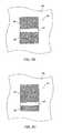
- FIG. 1Bis a simplified plan view of the printed image 20 on the substrate 29 , which could be a document, such as a bank note or stock certificate, at a first selected viewing angle.
- the printed imagecan act as a security and/or authentication feature because the illusive image will not photocopy and cannot be produced using conventional printing techniques.
- the first portion 22appears bright and the second portion 24 appears dark.
- the section line 40indicates the cross section shown in FIG. 1A .
- the transition 25 between the first and second portionsis relatively sharp.
- the documentcould be a bank note, stock certificate, or other high-value printed material, for example.
- FIG. 1Cis a simplified plan view of the printed image 20 on the substrate 29 at a second selected viewing angle, obtained by tilting the image relative to the point of view.
- the first portion 22now appears dark, while the second portion 24 appears light.
- the tilt angle at which the image flip-flopsdepends on the angle between the alignment planes of the flakes in the different portions of the image. In one sample, the image flipped from light to dark when tilted through about 15 degrees.
- FIG. 2Ais a simplified cross section of a printed image 42 of a kinematic optical device that will be referred to as a “rolling bar” for purposes of discussion, according to another embodiment of the present invention.
- the imageincludes pigment flakes 26 surrounded by a transparent carrier 28 printed on a substrate 29 .
- the pigment flakesare aligned in a curving fashion.
- the region(s) of the rolling bar that reflect light off the faces of the pigment flakes to the viewerappear lighter than areas that do not directly reflect the light to the viewer.
- This imageprovides a light band(s) or bar(s) that appear to move (“roll”) across the image when the image is tilted with respect to the viewing angle (assuming a fixed illumination source(s)).
- FIG. 2Bis a simplified plan view of the rolling bar image 42 at a first selected viewing angle.
- a bright bar 44appears in a first position in the image between two contrasting fields 46 , 48 .
- FIG. 2Cis a simplified plan view of the rolling bar image at a second selected viewing angle.
- the bright bar 44appears to have “moved” to a second position in the image, and the sizes of the contrasting fields 46 ′, 48 ′ have changed.
- the alignment of the pigment flakescreates the illusion of a bar “rolling” down the image as the image is tilted (at a fixed viewing angle and fixed illumination). Tilting the image in the other direction makes the bar appear to roll in the opposite direction (up).
- the barmay also appear to have depth, even though it is printed in a plane.
- the virtual depthcan appear to be much greater than the physical thickness of the printed image.
- the tilting of the flakes in a selected patternreflects light to provide the illusion of depth or “3D”, as it is commonly referred to.
- a three-dimensional effectcan be obtained by placing a shaped magnet behind the paper or other substrate with magnetic pigment flakes printed on the substrate in a fluid carrier.
- the flakesalign along magnetic field lines and create the 3D image after setting (e.g. drying or curing) the carrier.
- the imageoften appears to move as it is tilted, hence kinematic 3D images may be formed.
- Flip-flops and rolling barscan be printed with magnetic pigment flakes, i.e. pigment flakes that can be aligned using a magnetic field.
- a printed flip-flop type imageprovides an optically variable device with two distinct fields that can be obtained with a single print step and using a single ink formulation.
- a rolling bar type imageprovides an optically variable device that has a contrasting band that appears to move as the image is tilted, similar to the semi-precious stone known as Tiger's Eye. These printed images are quite noticeable and the illusive aspects would not photocopy.
- Such imagesmay be applied to bank notes, stock certificates, software documentation, security seals, and similar objects as authentication and/or anti-counterfeiting devices. They are particularly desirable for high-volume printed documents, such as bank notes, packaging, and labels, because they can be printed in a high-speed printing operation, as is described below in Section III.
- FIG. 3Ais a simplified cross view of a portion of an apparatus 50 for producing a flip-flop type image.
- the flakes 26are arranged in a V-shaped manner where both branches of the V represent directions of the tilt and the apex represents a transition point. Such orientation of the flakes is possible when two magnetic fields oppose each other.
- Two magnets 52 , 54are aligned with opposing poles (in this case north-north).
- the magnetswere assumed to be 2′′W by 1.5′′H NdFeB magnets 40MOe spaced 0.125 inches between the north poles.
- the type of magnet(material and strength) is selected according to the material of the flake, viscosity of the paint vehicle, and a substrate translation speed.
- neodymium-boron-iron, samarium-cobalt, and/or ALNICO magnetcan be utilized.
- the optimum distance between magnetsis important for the formation of the uniformity of the optical effect for a particular printed image size.
- the image 56is printed on a thin printing or painting substrate 58 , such as a sheet of paper, plastic, film, or card stock in a previous printing step, which is not illustrated in this figure.
- a thin printing or painting substrate 58such as a sheet of paper, plastic, film, or card stock in a previous printing step, which is not illustrated in this figure.
- several imagesare printed on the substrate, which is subsequently cut into individual documents, such as printing a sheet of banknotes that is cut into currency.
- the carrier 28is still wet or at least sufficiently fluid to allow alignment of the magnetic flakes with the magnets.
- the carriertypically sets shortly after alignment to allow handling of the printed substrate without smearing the image.
- the magnetic flakes 26follow direction of magnetic lines 60 and tilt.
- FIG. 3Bis a simplified cross-section of a portion of an apparatus for producing a flip-flop type image where the magnets 52 , 54 are mounted on a base 62 made from a metal alloy with high magnetic permeability, such as S UPERMALLOY . It is easier to make an assembly of several magnets if they are attached to a base, and the base provides a path for the magnetic field on the opposite side of the magnet, and alters the magnetic field lines on the print side of the assembly.
- the magnetic baseacts as a shunt for the magnetic field and reduces the magnetic field behind (“underneath”) the assembly, thus screening objects near the backside from high magnetic fields and forces.
- the magnetic basealso holds the magnets securely in position without screws, bolts, welds, or the like. Magnetic field circulates inside the base 62 providing uniformity of the field between the magnets. The field is the most intensive in the gap between magnets and above it.
- FIG. 3Cillustrates the calculated magnitude of the field intensity across the apparatus of FIG. 3B .
- Intensityis low near the edges of magnets, and becomes very high in the middle, providing a sharp transition between the flakes in adjacent portions of the image.
- FIG. 4is a simplified schematic of a magnetic assembly 64 that can be installed in the in-line printing or painting equipment.
- Permanent magnets 66 , 68 , 70 , 72 , 74 , 76 with their north and south poles indicated with “N” and “S”, respectively, similar to those illustrated in FIG. 3B ,are attached to the base 62 by magnetic attraction.
- the magnetsmay be magnetic bars, or may be segmented. That is, rows of magnets, e.g. 74 , 76 , etc., may be used.
- Plastic spacers(not shown in the picture) may be inserted between magnets to prevent their collision and provide safety.
- the assemblyis enclosed in a case 78 with a cover 80 .
- the case and covermay be aluminum or other non-magnetic material, for example.
- a plastic or paper substrate 29 with printed fields 20 ′moves at high speed over the top of the assembly in the direction of the arrows 82 in such way that the intersections of magnetic field lines goes through the printed fields. It is possible to align the substrate to the magnetic assembly so that the intersections of magnetic field lines pass through the centers of the fields. Alternatively, the centers between the magnets may be offset from the centers of the printed fields. Similarly, the substrate could be a continuous roll, rather than sequential sheets. In many cases, several sets of images are printed on a sheet, and the sheet is cut into individual documents, such as bank notes, after the printing is completed.
- a drier for water- or solvent-based paints or inks (not shown in the picture) or UV-light source for photopolymerstypically follows the magnetic assembly shortly in the line to dry the ink or paint vehicle and fix re-oriented flakes in their aligned positions. It is generally desirable to avoid magnetizing flakes before application, as they may clump together. Pigment flakes with layers of nickel or P ERMALLOY about 100–150 nm thick have been found to be suitable.
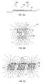
- FIG. 5Ais a simplified cross section of an apparatus for producing a flip-flop type image with a sharper transition, according to an embodiment of the present invention.
- Two NdFeB magnets 84(modeled as being 2′′W by 1.5′′H each) are placed on the magnetic base 62 facing with their north poles “up”. The distance between magnets is about one inch.
- a blade 88 made of a high-permeability metal or metal alloy, such as S UPERMALLOYis attached to the base between the magnets. The point of attack of the tip 90 of the blade is in the range of about 5 degrees to about 150 degrees. The blade reshapes the magnetic field lines, pulling them closer and making the tip as a point where the magnetic field lines originate.
- FIG. 5Bis a simplified cross section of an apparatus for producing an image according to another embodiment of the present invention.
- Shaped S UPERMALLOY caps 92are placed on the top of magnets 84 to bend the magnetic field lines, as illustrated. The caps bend the field, bringing it closer to the tip, which makes the V-shape transition of the lines even sharper.
- FIG. 5Cis a simplified cross section of a portion of the apparatus illustrated in FIG. 5B , showing the orientation of the flakes in such a magnetic device.
- the substrate 29is placed on the top of the device sliding along the caps 92 (or magnets, in the case of FIG. 5A ) in the direction from the viewer into the page.
- the printed image 85is located above the tip.
- the flakes 26follow magnetic lines 94 and tilt accordingly. This view more clearly shows the pointed nature of the tip of the blade, which produces a sharp transition between the two areas of the illusive image.
- FIG. 5Dis a graph illustrating the calculated magnitude of field intensity for the apparatus of FIGS. 5B and 5C .
- the field intensityis narrower compared with the field intensity plot of FIG. 3C , and produces a sharper transition.
- FIG. 6is a simplified schematic of a magnetic assembly 100 that can be installed in the in-line printing or painting equipment.
- Permanent magnets 84 with their north and south poles as illustrated in FIGS. 5A and 5Bare mounted on a magnetic base 62 . Alternatively, the south poles could be facing up.
- Cap plates 92are magnetically attached to the top of magnets.
- Blades 88are mounted on the base with their edges extending along the direction of translation 82 of the substrates 29 , 29 ′.
- the in-line magnets 84can be installed either next to each other or with a gap 102 between them.
- the magnetic assemblyis typically enclosed in a case 78 with a cover plate 80 .
- Fields 104 ′ printed on the substrate 29have generally nonoriented flakes. Some alignment of the flakes may occur as an artifact of the printing process, and generally some of the flakes tending to align in the plane of the substrate. When the substrate moves at high speed in the direction indicated by the arrow 82 above the magnetic assembly, the flakes change their orientation along lines of the magnetic field forming an illusive image 104 (flip-flop). The image has two areas which reflect light in different directions and a relatively sharp border (transition) between them.
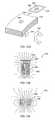
- FIG. 7Ais a simplified cross section of another embodiment of the invention for forming a semi-circular orientation of flakes in paint or ink for a rolling bar type image.
- a thin permanent magnet 106is magnetized through its thin section, as illustrated.
- the magnethas circular magnetic lines 108 on its ends.
- the substrate 29 with the printed magnetic flakes dispersed in a fluid carriermoves along the magnet from the viewer into the paper.
- the flakes 26tilt along direction of the magnetic lines 108 and form a semi-circle pattern above the magnet.
- FIG. 7Bis a simplified perspective view of an apparatus in accordance with FIG. 7A .
- the substrate 29moves across the magnet 106 in the direction of the arrow.
- the image 110forms a rolling bar feature 114 , which will appear to move up and down as the image is tilted or the viewing angle is changed.
- the flakes 26are shown as being tilted in relation to the magnetic field lines.
- the imageis typically very thin, and the flakes might not form a hump, as illustrated, but generally align along the magnetic field lines to provide the desired arched reflective properties to create a rolling bar effect.
- the barappeared to roll up and down the image when tilted through an angle of about 25 degrees in one example.
- the intensity of the rolling bar effectcould be enhanced by chamfering 116 the trailing edge 118 of the magnet. It is believed that this gradually reduces the magnetic field as the image clears the magnet. Otherwise, the magnetic transition occurring at a sharp corner of the magnet might re-arrange the orientation of the flakes and degrade the visual effect of the rolling bar. In a particular embodiment, the corner of the magnet was chamfered at an angle of thirty degrees from the plane of the substrate.
- An alternative approachis to fix the flakes before they pass over the trailing edge of the magnet. This could be done by providing a UV source part way down the run of the magnet, for UV-curing carrier, or a drying source for evaporative carriers, for example.
- FIG. 7Cis a simplified side view of another apparatus 120 for forming a rolling bar image according to another embodiment of the present invention.
- the rolling bar effectis obtained using two magnets 122 .
- the magnetic pigment flakes 26orient themselves in the liquid carrier 28 along the oval magnetic field lines.
- FIG. 8is a simplified schematic of an apparatus 130 for printing rolling bar images according to an embodiment of the present invention that can be installed in the in-line printing or painting equipment.
- Thin vertical magnets 106with their north-south polarization as shown, are installed in a plastic housing 132 that separates the magnets at selected distances, generally according to the location of the printed fields 110 ′ on the substrate 29 .
- the magnetsare aligned in such fashion that they oppose each other. In other words, the north pole of one row of magnets faces the north pole of an adjacent row, while the south pole faces the south pole of an adjacent row of magnets from the other side.
- the apparatus FIG. 8does not have a metallic base.
- a base made from a metal having high magnetic permeabilitywould reduce the strength of a magnetic field on the side of the magnet that is responsible for the tilt of the flakes.
- the magnetsare inserted in slits of the plastic housing in such way that the upper part of the magnets goes underneath of the center of printed fields, but could be offset from the center.
- the substrate 29 , 29 ′move at high speed atop the magnets in the direction of the arrows 82 . Passing above the magnets, the flakes in the printed images orient themselves along lines of the magnetic field, creating an illusive optical effect in rolling bar image 110 .
- FIG. 9Ais a simplified cross section of another optical effect that is possible to achieve using magnetic alignment techniques in high-speed printing processes.
- the pigment flakes 26 in the image 134are generally aligned parallel to each other, but not parallel to the surface of the substrate 29 . Again, it is not necessary that each flake be perfectly aligned with each other flake, but the visual impression obtained is essentially in accordance with the illustration. Alignment of the majority of the flakes in the manner illustrated causes an interesting optical effect. The image looks dark when observed from one direction 136 and bright when observed from another direction 138 .
- FIG. 9Bis a simplified cross section of a apparatus 139 according to an embodiment of the present invention capable of producing the image illustrated in FIG. 9A .
- a printed field 134 with still-wet paint or inkis placed above permanent magnet 140 with offset position relatively the magnet axes.
- the analysis of the magnetic fieldwas modeled assuming a 2′′ by 1.5′′ NdFeB 40MOe magnet. The magnitude of the field intensity is lower in the center of the magnet and higher towards its edges.
- electromagnetsmight be used in some embodiments, but it is difficult to obtain magnetic fields as high as can be obtained with current supermagnets in the confined spaces of a high-speed printing machine.
- the coils of electromagneticalso tend to generate heat, which can affect the curing time of the ink or paint and add another process variable. Nonetheless, electromagnetic may be useful in some embodiments of the invention.
- FIG. 9Cis a simplified cross section of an apparatus according to another embodiment of the present invention.
- Magnets 142 , 142 ′ having a diamond-shaped cross sectionare used to spread the magnetic field and make it wider.
- the apparatuswas modeled with three two-inches by one and a half inches NdFeB magnets arranged one inch from each other.
- the magnetsshow a cross-section of a magnetic assembly for reorientation of flakes in a magnetic field.
- the substrate 29moves at a high speed in the direction from the viewer into the drawing.
- Two magnetshave their north pole facing up while the intervening magnet 142 ′ has its south pole facing up.
- Each magnethas the same field intensity as the magnets illustrated in FIG. 9B , but provides a wider area for placement of the field 134 ′ for orienting the flakes 26 .
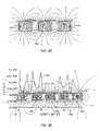
- FIG. 9Dis a simplified cross section of an apparatus according to yet another embodiment of the present invention.
- An effect similar to that obtained with the apparatus illustrated in FIG. 9Ccan be obtained with magnets 144 , 144 ′ having a roof-shaped cross-section, as well as with magnets having hexagonal, rounded, trapezoidal, or other cross-sections.
- Different shapes of magnetsprovide different performance that can create various printed or painted images with tilted flakes.
- the magnitude of magnetic field intensitycan be very different for magnets having different shapes (cross sections).
- FIG. 9Eillustrates the calculated magnetic field intensity for a five-magnet apparatus.
- the first magnet 142is a diamond-shaped NdFeB 40MOe magnet with dimensions close to 2′′ by 1.5′′ with its north pole facing up.
- the second magnet 146is a rectangular 2′′ by 1.5′′ NdFeB 40MOe magnet with its south pole facing the substrate 29 .
- the third magnet 148is a NdFeB 40MOe magnet with rounded top. This magnet has its north pole facing the substrate.
- the fourth magnet 150has its south pole facing up, and is roof-shaped (with the angle of the tip being about 185°).
- the fifth magnet 152is also roof-shaped but the angle of the tip is about 175°.
- the curve 160shows the calculated magnitude of magnetic field intensity in this illustrative assembly.
- Shapes of the field intensityare different for different magnets.
- the field intensityis low in the center of rectangular, diamond and roof-shaped magnets while it becomes almost flat at 380,000 A/m for the rounded magnet 148 .
- the curveshows that shaping of the magnet helps to get a field intensity that will be enough to provide a torque of the flake to orient it.
- FIG. 10Ais a simplified side view of an apparatus 162 according to an embodiment of the present invention that tilts the flakes in a preferred direction and is suitable for adaptation to a high-speed printing process.
- Three 2′′ by 1.5′′ NdFeB 40MOe magnets 164 , 164 ′are tilted 10° relative to the substrate 29 and printed images 166 . Flakes 26 follow magnetic lines and re-orient themselves. The magnets have the same alignment similar to the alignment shown in FIG. 9D .
- Two of the magnets 164have their north poles up and the magnet 164 ′ between them has its south pole facing the substrate 29 .
- the printed images 166should be placed above the central axis of the magnet to take advantage of the tilted magnetic field lines generated by the tilted magnets. Such arrangement produces uniform tilt of the flake on an area that is larger than for the magnetic assemblies described in reference to FIGS. 9A–9E .
- Magnetic lines in the fieldare not parallel. The difference is minor in the near order and becomes larger with increase of a distance between the lines. It means, that on a large printed image, placed in magnetic field, all flakes would have different tilt resulting in a non-consistent image appearance. The inconsistency can be reduced by deflecting of magnetic lines toward the center of the magnet to keep them more parallel. It is possible to do with small auxiliary magnets.
- FIG. 10Bis a simplified side view of an apparatus 168 according to an embodiment of the present invention including auxiliary magnets 170 , 170 ′.
- the tilted primary magnets 172 , 172 ′are arranged similar to the magnets shown in FIG. 10A , with alternating magnets presenting alternating poles (north-south-north) next to the substrate 29 .
- the smaller auxiliary magnetsare located beneath the substrate and between the larger primary magnets.
- the auxiliary magnetsare arranged so that the north pole of an auxiliary magnet faces the north pole of a primary magnet, and its south pole faces the south pole of a primary magnet. In such an arrangement, two fields (north-north, south-south) oppose each other and magnetic lines become deflected toward the center of the primary magnets.
- FIG. 10Cis a simplified plot showing the calculated field intensity for the magnetic assemblies shown in FIGS. 10A and 10B , represented by curves 174 and 176 , respectively.
- the substrate 29 , primary magnets 172 , 172 ′ and auxiliary magnets 170 , 170 ′are shown to illustrate how the plots relate to the assembly dimensions, although the auxiliary magnets are only relevant to the plot of the second curve 176 .
- the first curve 174shows how the magnitude of field intensity of the assembly in FIG. 10A changes in the direction from one edge of the substrate to another.
- the curvehas two minima 178 , 180 corresponding to the center of the primary magnets 172 , 172 ′.
- a central axis 182 of the center magnet 172 ′shows where the center of the magnet and the plot of field intensity coincide.
- auxiliary magnets 170 , 170 ′shifts magnitude of field intensity to the left.
- the second curve 176shows magnitude of field intensity of an assembly according to FIG. 10B .
- the maxima 184 , 186 on the curveare shifted to the left relative to the first curve 174 associated with FIG. 10A . This shows that opposing fields on the auxiliary magnets deflect the fields of the primary magnets.
- FIG. 11Ais a simplified side view of an apparatus 190 for aligning magnetic pigment flakes in printed fields 192 in the plane of a substrate after printing.
- Magnets 194 , 196are arranged to produce magnetic field lines 198 essentially parallel to the surface of the substrate 29 .
- the flakesalign essentially parallel to the substrate when applied (printed), but are “pulled” out of plane when the printing screen is lifted, for example. This disorganization of the flakes tends to reduce the visual effect of the print, such as a reduction in chroma.
- magnetic color-shifting pigment flakeswere applied to a paper card using a conventional silkscreen process.
- the same inkwas applied to another paper card, but before the ink carrier dried, a magnet was used to re-orient the flakes in the plane of the card.
- the difference in visual appearance, such as the intensity of the colors,was very dramatic. Measurements indicated that a 10% improvement in chroma had been attained. This level of improvement is very significant, and it is believed that it would be very difficult to achieve such an improvement through modifications of the pigment flake production techniques, such as changes to the substrate and thin film layers of the flake. It is believed that even greater improvement in chroma is possible, and that a 40% improvement might be obtained when magnetic re-alignment techniques are applied to images formed using an Intaglio printing process.
- FIG. 11Bis a simplified side view of a portion of an apparatus for enhancing the visual quality of an image printed with magnetically alignable flakes according to another embodiment of the present invention.
- Magnets 194 , 196create magnetic field lines 198 that are essentially parallel to the substrate 29 , which causes the magnetic pigment flakes 26 in the fluid carrier 28 to flatten out.
- the magnetscan be spaced some distance apart to provide the desired magnetic field, and the apparatus can be adapted to an in-line printing process.
- FIG. 12Ais a simplified side-view schematic of a portion of a printing apparatus 200 according to an embodiment of the present invention.
- Magnets 202 , 204 , 206 , 208are located inside an impression roller 210 , forming a pattern that correlates with a printed image.
- the substrate 212such as a continuous sheet of paper, plastic film, or laminate, moves between the print cylinder 214 and the impression roller 210 at high speed.
- the print cylindertakes up a relatively thick layer 212 of liquid paint or ink 215 containing magnetic pigment from a source container 216 .
- the paint or inkis spread to the desired thickness on the print cylinder with a blade 218 .
- the magnets in the impression rollerorient (i.e. selectively align) the magnetic pigment flakes in at least part of the printed image 220 .
- a tensioner 222is typically used to maintain the desired substrate tension as it comes out of the impression roller and print cylinder, and the image on the substrate is dried with a drier 224 .
- the driercould be heater, for example, or the ink or paint could be UV-curable, and set with a UV lamp.
- FIG. 12Bis a simplified sideview schematic of a portion of printing apparatus 200 ′ according to another embodiment of the present invention.
- Magnets 202 ′, 204 ′, 206 ′, 208 ′are installed in the tensioner 222 ′ or other roller.
- the magnetsorient the magnetic pigment flakes in the printed images before the fluid carrier of the ink or paint dries or sets.
- a wet printed image 219comes off the impression roller 210 ′ and print cylinder 214 with flakes in a non-selected orientation, and a wet image 220 ′ is oriented by a magnet 206 ′ in the tensioner 222 ′ before the flakes are fixed.
- the drier 224speeds or completes the drying or curing process.
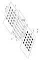
- FIG. 12Cis a simplified perspective view of a magnetic roller 232 according to an embodiment of the present invention.
- the rollercould be a print cylinder or tensioner, as discussed in conjunction with FIGS. 12A and 12B , or another roller in a printing system that contacts the print substrate before the ink or paint is fixed.
- Magnetic assemblies 234 , 236 , 238 , 240 , 241are attached to the roller with screws 242 , which allow the magnetic assemblies to be changed without removing the roller from the printer.
- the magnetic assembliescould be configured to produce flip-flop 234 , 236 or rolling bar 238 images, or could be patterned magnetic material 240 , 241 that produces a patterned image on the printed substrate, or other selected magnetic configuration.
- the magnetic structures on the rollerare aligned to the sheet or roll to provide the desired magnetic field pattern to fields printed on the substrate with magnetic pigment flakes.
- the illustrated patternsrepresent flat patterns that follow the curve of the circumference of the roller.
- the magnetic structurecould be built into the roller, or a roller with a suitable surface material could be magnetized in selected patterns.
- FIG. 12Dis a simplified perspective section of a portion of a roller 232 ′ with a magnetic assembly 244 embedded in the roller.
- the magnetic assemblyhas a cross section in the shape of a star, and it surface 244 ′ is essentially flush with the surface of the roller.
- the magnetic assemblycould be shaped permanently magnetized material, as illustrated in FIG. 12F , or have a tip section of S UPERMALLOY , M U - METAL , or similar material, as illustrated in FIG. 12E , below.
- the rollerrotates in the direction of the first arrow 246 and a paper or film substrate 248 travels in the direction of the second arrow 250 .
- a field 252 including magnetic pigment flakeshas been printed on the substrate.
- the fieldwas over the surface of the star-shaped magnetic assembly when the roller was proximate to the substrate, and an illusive optical feature 254 in the shape of a star was formed in the field.
- the magnetic pigment flakesare fixed while the magnetic assembly is in contact with the substrate.
- the illusive optical effect 254is a star with an apparent depth much deeper than the physical thickness of the printed field.
- a solvent-based (including water-based) carriertends to reduce in volume as the solvent evaporates. This can cause further alignment, such as tilting partially tilted flakes toward the plane of the substrate.
- UV-curable carrierstend not to shrink, and the alignment of the magnetic pigment flakes after contact with the magnetic field pattern tends to be more precisely preserved. Whether it is desired to preserve the alignment, or enhance the alignment by evaporation of the solvent in the carrier, depends on the intended application.
- FIG. 12Eis a simplified side view of a magnetic assembly 256 with a permanent magnet 258 providing the magnetic field that is directed to the substrate 248 by a patterned tip 260 of S UPERMALLOY or other high-permeability material.
- the modeled magnetic field lines 262are shown for purposes of illustration only. Some “supermagnet” materials are hard, brittle, and generally difficult to machine into intricate shapes.
- S UPERMALLOYis much easier to machine than NdFeB magnets, for example, and thus can provide an intricate magnetic field pattern with sufficient magnetic field strength to align the magnetic pigment flakes in the desired pattern.
- the low remnant magnetization of S UPERMALLOY and similar alloysmake them easier to machine, as well.
- FIG. 12Fis a simplified side view of a magnetic assembly 264 with a shaped permanent magnet 258 ′.
- the entire length of the magnetdoes not have to be shaped, but only that portion that produces the desired field pattern at the substrate 248 .
- some materials that are commonly used to form permanent magnetsare difficult to machine, simple patterns may be formed in at least the tip section.
- Other materials that form permanent magnetsare machinable, and may provide sufficient magnetic strength to produce the desired illusive optical effect.
- magnet alloysmight be cast or formed into relatively complex shapes using powder metallurgy techniques.
- FIG. 13Ais a simplified flow chart of a method 300 of printing an image on a substrate according to an embodiment of the present invention.
- a fieldis printed on a thin planar substrate, such as a sheet of paper, plastic film, or laminate, using magnetic pigment flake in a fluid carrier (step 302 ).
- the substrateis moved in a linear fashion relative to a magnet assembly (step 304 ) to orient the magnetic pigment flakes (step 306 ).
- the imageis fixed (i.e. dried or set) (step 308 ) to obtain an optically variable image resulting from the alignment of the pigment flakes.
- the substrateis moved past a stationary magnet assembly.
- the imagemay have additional optically variable effects, such as color-shifting.
- the magnet assemblyis configured to provide a flip-flop image.
- the magnet assemblyis configured to provide a rolling bar image.
- the thin planar substrateis a sheet that is printed with several images. The images on the sheet can be the same or different, and different inks or paints can be used to print the images on the sheet. Similarly, different magnetic assemblies can be used to create different images on a single sheet of substrate.
- the substratecan be an essentially continuous substrate, such as a roll of paper.
- FIG. 13Bis a simplified flow chart of a method 310 of printing an image on a moving substrate according to another embodiment of the present invention.
- a substrateis moved past a rotating roller with embedded magnets (step 312 ) to align magnetic pigment flakes (step 314 ) that have been applied to the substrate in a fluid carrier.
- the magnetic pigment flakesare then fixed (step 316 ) to obtain an optically variable image resulting from the alignment of the pigment flakes.
- the magnetic pigment flakesare aligned by magnets in an impression roller as the ink or paint is printed onto the substrate.
- the magnetic pigment flakesare aligned by magnets in a subsequent roller, such as a tensioner. After the flakes are aligned the ink or paint is dried or cured to fix the image.
- roller(s)may be incorporated into the roller(s), including magnetic structures for forming flip-flop or rolling bar images.
- Other magnetic structuressuch as magnets with a face having a selected shape, can be incorporated into the rollers to provide high-speed printing of optically variable images.
- a magnet having a ring-shape on its facecan produce a “fish-eye” effect in a field printed with magnetic pigment flakes.
- the tensioner or other roller near the driercan avoid the problems associated with the image in the magnetic pigment flakes being degraded as the image leaves the trailing edge of the face of the magnet.
- the tangential separation of the substrate from the magnetic rolleravoids degradation of the magnetically aligned image.
- the substratecould be stationary, and the magnetic roller could be rolled across the substrate.
Landscapes
- Engineering & Computer Science (AREA)
- Mechanical Engineering (AREA)
- Accounting & Taxation (AREA)
- Finance (AREA)
- Business, Economics & Management (AREA)
- Printing Methods (AREA)
- Credit Cards Or The Like (AREA)
- Application Of Or Painting With Fluid Materials (AREA)
- Inks, Pencil-Leads, Or Crayons (AREA)
- Pigments, Carbon Blacks, Or Wood Stains (AREA)
- Soft Magnetic Materials (AREA)
- Manufacturing Of Magnetic Record Carriers (AREA)
- Hard Magnetic Materials (AREA)
Abstract
Description
Claims (9)
Priority Applications (48)
| Application Number | Priority Date | Filing Date | Title |
|---|---|---|---|
| US10/386,894US7047883B2 (en) | 2002-07-15 | 2003-03-11 | Method and apparatus for orienting magnetic flakes |
| KR1020107006276AKR101176090B1 (en) | 2002-07-15 | 2003-07-01 | An article for producing a rolling bar |
| EP10179367AEP2263806A1 (en) | 2002-07-15 | 2003-07-01 | Method and apparatus for orienting magnetic flakes and image obtained by said method |
| DE60335544TDE60335544D1 (en) | 2002-07-15 | 2003-07-01 | MAGNETIC PLANARIZATION OF PIGMENT FLAKES |
| CNB038166100ACN1330434C (en) | 2002-07-15 | 2003-07-01 | Magnetic planarization of pigment flakes |
| AT03764338TATE493208T1 (en) | 2002-07-15 | 2003-07-01 | MAGNETIC PLALARIZATION OF PIGMENT FLAKES |
| EP10012861.0AEP2308608B1 (en) | 2002-07-15 | 2003-07-01 | Apparatus for orienting magnetic flakes |
| JP2005505110AJP5033329B2 (en) | 2002-07-15 | 2003-07-01 | Magnetic flattening of pigment flakes. |
| ES09177912TES2425615T5 (en) | 2002-07-15 | 2003-07-01 | Method to orient the magnetic flakes |
| EP03764338AEP1519794B1 (en) | 2002-07-15 | 2003-07-01 | Magnetic planarization of pigment flakes |
| EP09177912.4AEP2165774B8 (en) | 2002-07-15 | 2003-07-01 | Method for orienting magnetic flakes |
| KR1020047021640AKR101024880B1 (en) | 2002-07-15 | 2003-07-01 | Self-Planning of Pigment Flakes |
| PCT/US2003/020665WO2004007095A2 (en) | 2002-07-15 | 2003-07-01 | Method and apparatus for orienting magnetic flakes and image obtained by said method |
| CNB038168359ACN100384546C (en) | 2002-07-15 | 2003-07-01 | Method and apparatus for orienting magnetic pigment flakes |
| ES03742356.3TES2443191T3 (en) | 2002-07-15 | 2003-07-01 | Procedure for the orientation of magnetic scales |
| TW092117980ATWI281419B (en) | 2002-07-15 | 2003-07-01 | Method and apparatus for orienting magnetic flakes |
| PT91779124TPT2165774E (en) | 2002-07-15 | 2003-07-01 | Method for orienting magnetic flakes |
| EP16150687.8AEP3059019B1 (en) | 2002-07-15 | 2003-07-01 | Image obtained by a method for orienting magnetic flakes |
| DK09177912.4TDK2165774T4 (en) | 2002-07-15 | 2003-07-01 | Method for determining the direction of magnetic flakes |
| JP2005505109AJP4421555B2 (en) | 2002-07-15 | 2003-07-01 | Method and apparatus for orienting magnetic flakes |
| PCT/US2003/020726WO2004007096A2 (en) | 2002-07-15 | 2003-07-01 | Magnetic planarization of pigment flakes |
| EP03742356.3AEP1545799B1 (en) | 2002-07-15 | 2003-07-01 | Method for orienting magnetic flakes |
| EP10179378.4AEP2263807B1 (en) | 2002-07-15 | 2003-07-01 | Image obtained by a method for orienting magnetic flakes |
| KR1020047021669AKR100991504B1 (en) | 2002-07-15 | 2003-07-01 | Method and apparatus for orienting magnetic flakes |
| KR1020107006277AKR101029846B1 (en) | 2002-07-15 | 2003-07-01 | Method of forming an illusive image |
| US11/022,106US7517578B2 (en) | 2002-07-15 | 2004-12-22 | Method and apparatus for orienting magnetic flakes |
| US11/252,681US8211509B2 (en) | 2002-07-15 | 2005-10-18 | Alignment of paste-like ink having magnetic particles therein, and the printing of optical effects |
| US11/313,165US7604855B2 (en) | 2002-07-15 | 2005-12-20 | Kinematic images formed by orienting alignable flakes |
| US11/278,600US8343615B2 (en) | 2002-07-15 | 2006-04-04 | Dynamic appearance-changing optical devices (DACOD) printed in a shaped magnetic field including printable fresnel structures |
| US11/461,870US7625632B2 (en) | 2002-07-15 | 2006-08-02 | Alignable diffractive pigment flakes and method and apparatus for alignment and images formed therefrom |
| US11/552,219US7876481B2 (en) | 1999-07-08 | 2006-10-24 | Patterned optical structures with enhanced security feature |
| US11/623,190US7934451B2 (en) | 2002-07-15 | 2007-01-15 | Apparatus for orienting magnetic flakes |
| US11/738,855US20070195392A1 (en) | 1999-07-08 | 2007-04-23 | Adhesive Chromagram And Method Of Forming Thereof |
| US11/865,451US7880943B2 (en) | 1999-07-08 | 2007-10-01 | Patterned optical structures with enhanced security feature |
| US12/233,667US9662925B2 (en) | 2001-07-31 | 2008-09-19 | Anisotropic magnetic flakes |
| US12/494,390US20090324907A1 (en) | 1999-07-08 | 2009-06-30 | Tamper evident and resisting informational article and method of producing same |
| US12/574,007US9027479B2 (en) | 2002-07-15 | 2009-10-06 | Method and apparatus for orienting magnetic flakes |
| US12/727,205US20100208351A1 (en) | 2002-07-15 | 2010-03-18 | Selective and oriented assembly of platelet materials and functional additives |
| US13/073,743US8276511B2 (en) | 2002-07-15 | 2011-03-28 | Apparatus for orienting magnetic flakes |
| US13/250,480US20120075701A1 (en) | 1999-07-08 | 2011-09-30 | Optically variable security devices |
| US13/627,703US8726806B2 (en) | 2002-07-15 | 2012-09-26 | Apparatus for orienting magnetic flakes |
| US13/689,110US9257059B2 (en) | 2001-07-31 | 2012-11-29 | Dynamic appearance-changing optical devices (DACOD) printed in a shaped magnetic field including printable fresnel structures |
| US14/644,556US20150185376A1 (en) | 1999-07-08 | 2015-03-11 | Optically variable security devices |
| US14/681,551US9522402B2 (en) | 2002-07-15 | 2015-04-08 | Method and apparatus for orienting magnetic flakes |
| US14/986,293US10173455B2 (en) | 2002-07-15 | 2015-12-31 | Dynamic appearance-changing optical devices (DACOD) printed in a shaped magnetic field including printable fresnel structures |
| US15/350,021US10059137B2 (en) | 2002-07-15 | 2016-11-12 | Apparatus for orienting magnetic flakes |
| US16/113,977US11230127B2 (en) | 2002-07-15 | 2018-08-27 | Method and apparatus for orienting magnetic flakes |
| US16/425,532US20190346596A1 (en) | 1999-07-08 | 2019-05-29 | Optically variable security devices |
Applications Claiming Priority (4)
| Application Number | Priority Date | Filing Date | Title |
|---|---|---|---|
| US39621002P | 2002-07-15 | 2002-07-15 | |
| US41054702P | 2002-09-13 | 2002-09-13 | |
| US41054602P | 2002-09-13 | 2002-09-13 | |
| US10/386,894US7047883B2 (en) | 2002-07-15 | 2003-03-11 | Method and apparatus for orienting magnetic flakes |
Related Parent Applications (2)
| Application Number | Title | Priority Date | Filing Date |
|---|---|---|---|
| US48925000AContinuation | 1999-07-08 | 2000-01-21 | |
| US12/574,007DivisionUS9027479B2 (en) | 2002-07-15 | 2009-10-06 | Method and apparatus for orienting magnetic flakes |
Related Child Applications (2)
| Application Number | Title | Priority Date | Filing Date |
|---|---|---|---|
| US10/666,318Continuation-In-PartUS6987590B2 (en) | 1999-07-08 | 2003-09-18 | Patterned reflective optical structures |
| US11/022,106Continuation-In-PartUS7517578B2 (en) | 1999-07-08 | 2004-12-22 | Method and apparatus for orienting magnetic flakes |
Publications (2)
| Publication Number | Publication Date |
|---|---|
| US20040051297A1 US20040051297A1 (en) | 2004-03-18 |
| US7047883B2true US7047883B2 (en) | 2006-05-23 |
Family
ID=31999561
Family Applications (4)
| Application Number | Title | Priority Date | Filing Date |
|---|---|---|---|
| US10/386,894Expired - LifetimeUS7047883B2 (en) | 1999-07-08 | 2003-03-11 | Method and apparatus for orienting magnetic flakes |
| US12/574,007Expired - LifetimeUS9027479B2 (en) | 2002-07-15 | 2009-10-06 | Method and apparatus for orienting magnetic flakes |
| US14/681,551Expired - LifetimeUS9522402B2 (en) | 2002-07-15 | 2015-04-08 | Method and apparatus for orienting magnetic flakes |
| US15/350,021Expired - LifetimeUS10059137B2 (en) | 2002-07-15 | 2016-11-12 | Apparatus for orienting magnetic flakes |
Family Applications After (3)
| Application Number | Title | Priority Date | Filing Date |
|---|---|---|---|
| US12/574,007Expired - LifetimeUS9027479B2 (en) | 2002-07-15 | 2009-10-06 | Method and apparatus for orienting magnetic flakes |
| US14/681,551Expired - LifetimeUS9522402B2 (en) | 2002-07-15 | 2015-04-08 | Method and apparatus for orienting magnetic flakes |
| US15/350,021Expired - LifetimeUS10059137B2 (en) | 2002-07-15 | 2016-11-12 | Apparatus for orienting magnetic flakes |
Country Status (9)
| Country | Link |
|---|---|
| US (4) | US7047883B2 (en) |
| EP (5) | EP2263807B1 (en) |
| JP (1) | JP4421555B2 (en) |
| KR (3) | KR101029846B1 (en) |
| CN (1) | CN100384546C (en) |
| AT (1) | ATE493208T1 (en) |
| DE (1) | DE60335544D1 (en) |
| TW (1) | TWI281419B (en) |
| WO (1) | WO2004007095A2 (en) |
Cited By (92)
| Publication number | Priority date | Publication date | Assignee | Title |
|---|---|---|---|---|
| US20040151827A1 (en)* | 2002-09-13 | 2004-08-05 | Flex Products, Inc., A Jds Uniphase Company | Opaque flake for covert security applications |
| US20050037192A1 (en)* | 2003-08-14 | 2005-02-17 | Flex Prodcuts, Inc., A Jds Uniphase Company | Flake for covert security applications |
| US20050106367A1 (en)* | 2002-07-15 | 2005-05-19 | Jds Uniphase Corporation | Method and apparatus for orienting magnetic flakes |
| US20060035080A1 (en)* | 2002-09-13 | 2006-02-16 | Jds Uniphase Corporation | Provision of frames or borders around opaque flakes for covert security applications |
| US20060077496A1 (en)* | 1999-07-08 | 2006-04-13 | Jds Uniphase Corporation | Patterned structures with optically variable effects |
| US20060097515A1 (en)* | 2002-07-15 | 2006-05-11 | Jds Uniphase Corporation | Kinematic images formed by orienting alignable flakes |
| US20060194040A1 (en)* | 2002-09-13 | 2006-08-31 | Jds Uniphase Corporation | Two-step method of coating an article for security printing |
| US20060198998A1 (en)* | 2002-07-15 | 2006-09-07 | Jds Uniphase Corporation | Dynamic appearance-changing optical devices (dacod) printed in a shaped magnetic field including printable fresnel structures |
| US20060219107A1 (en)* | 2003-06-30 | 2006-10-05 | Matthias Gygi | Printing machine |
| US20060255013A1 (en)* | 2003-06-05 | 2006-11-16 | Karlheinz Bock | Method and Device for Producing a System Having a Component Applied to a Predetermined Location of a Surface of a Substrate |
| US20060263539A1 (en)* | 2002-07-15 | 2006-11-23 | Jds Uniphase Corporation | Alignable Diffractive Pigment Flakes And Method And Apparatus For Alignment And Images Formed Therefrom |
| US20070115337A1 (en)* | 2005-11-18 | 2007-05-24 | Jds Uniphase Corporation | Magnetic Plate For Printing Of Optical Effects |
| US20070139744A1 (en)* | 2002-09-13 | 2007-06-21 | Jds Uniphase Corporation | Security Device With Metameric Features Using Diffractive Pigment Flakes |
| US20070172261A1 (en)* | 2002-07-15 | 2007-07-26 | Jds Uniphase Corporation | Apparatus For Orienting Magnetic Flakes |
| US20070183047A1 (en)* | 2000-01-21 | 2007-08-09 | Jds Uniphase Corporation | Optically Variable Security Devices |
| US20070195392A1 (en)* | 1999-07-08 | 2007-08-23 | Jds Uniphase Corporation | Adhesive Chromagram And Method Of Forming Thereof |
| US20070206249A1 (en)* | 2006-03-06 | 2007-09-06 | Jds Uniphase Corporation | Security Devices Incorporating Optically Variable Adhesive |
| US20080003413A1 (en)* | 2002-09-13 | 2008-01-03 | Jds Uniphase Corporation | Stamping A Coating Of Cured Field Aligned Special Effect Flakes And Image Formed Thereby |
| US20080024847A1 (en)* | 1999-07-08 | 2008-01-31 | Jds Uniphase Corporation | Patterned Optical Structures With Enhanced Security Feature |
| US20080074787A1 (en)* | 2006-09-22 | 2008-03-27 | Board Of Regents Of The Nevada System Of Higher Education On Behalf Of The University Of Nevada, | Devices and methods for storing data |
| US20080084634A1 (en)* | 2006-09-22 | 2008-04-10 | Board Of Regents Of The Nevada System Of Higher Education On Behalf Of The University Nevada | Devices and methods for storing data |
| US20080088895A1 (en)* | 2006-03-06 | 2008-04-17 | Jds Uniphase Corporation | Article With Micro Indicia Security Enhancement |
| US20090072185A1 (en)* | 2001-07-31 | 2009-03-19 | Jds Uniphase Corporation | Anisotropic Magnetic Flakes |
| US20090200791A1 (en)* | 2006-07-19 | 2009-08-13 | Sicpa Holding S.A. | Oriented Image Coating on Transparent Substrate |
| WO2009105040A1 (en) | 2008-02-19 | 2009-08-27 | Bilcare Technologies Singapore Pte. Ltd. | A reading device for identifying a tag or an object adapted to be identified, related methods and systems |
| US20090291268A1 (en)* | 2008-05-26 | 2009-11-26 | San Fang Chemical Industry Co., Ltd. | Resin surface layer and method of fabricating the same, composite having the resin surface layer and method of fabricating the same |
| US20100170408A1 (en)* | 2007-02-20 | 2010-07-08 | Kba-Giori S.A. | Cylinder Body for Orienting Magnetic Flakes Contained in an Ink or Varnish Vehicle Applied on a Sheet-Like or Web-Like Substrate |
| US20100208351A1 (en)* | 2002-07-15 | 2010-08-19 | Nofi Michael R | Selective and oriented assembly of platelet materials and functional additives |
| EP2266710A2 (en) | 2006-01-17 | 2010-12-29 | JDS Uniphase Corporation | Apparatus for orienting magnetic flakes |
| EP2325266A1 (en) | 2009-11-24 | 2011-05-25 | JDS Uniphase Corporation | A mixture of magnetically orientable color shifting flakes and non-magnetically orientable color shifting flakes exhibiting a common color |
| US8025952B2 (en) | 2002-09-13 | 2011-09-27 | Jds Uniphase Corporation | Printed magnetic ink overt security image |
| EP2402401A1 (en) | 2010-06-30 | 2012-01-04 | JDS Uniphase Corporation | Magnetic multilayer pigment flake and coating composition |
| EP2468423A1 (en) | 2010-12-27 | 2012-06-27 | JDS Uniphase Corporation | System and method for forming an image on a substrate |
| WO2013106462A1 (en) | 2012-01-12 | 2013-07-18 | Jds Uniphase Corporation | Article with curved patterns formed of aligned pigment flakes |
| US20130183067A1 (en)* | 2010-09-24 | 2013-07-18 | Sicpa Holding Sa | Device, system and method for producing a magnetically induced visual effect |
| US8605322B2 (en) | 2008-01-24 | 2013-12-10 | Quad/Graphics, Inc. | Printing using color changeable material |
| US8658280B2 (en) | 2002-09-13 | 2014-02-25 | Jds Uniphase Corporation | Taggent flakes for covert security applications having a selected shape |
| US8789925B1 (en) | 2013-02-01 | 2014-07-29 | Xerox Corporation | Method and apparatus for printing of magnetic inks |
| DE102014205638A1 (en) | 2013-03-27 | 2014-10-02 | Jds Uniphase Corp. | Optical device having an illusory optical effect and method of manufacture |
| WO2014177448A1 (en) | 2013-05-02 | 2014-11-06 | Sicpa Holding Sa | Processes for producing security threads or stripes |
| US8893614B2 (en) | 2007-05-10 | 2014-11-25 | Kba-Notasys Sa | Device and method for magnetically transferring indicia to a coating composition applied to a substrate |
| US9027479B2 (en) | 2002-07-15 | 2015-05-12 | Jds Uniphase Corporation | Method and apparatus for orienting magnetic flakes |
| WO2015086257A1 (en) | 2013-12-13 | 2015-06-18 | Sicpa Holding Sa | Processes for producing effects layers |
| EP2946938A1 (en) | 2014-05-23 | 2015-11-25 | Merck Patent GmbH | Method for the laser treatment of coatings |
| US9199502B2 (en) | 2011-02-04 | 2015-12-01 | Sicpa Holding Sa | Security element displaying a visual motion effect and method for producing same |
| EP3023259A2 (en) | 2014-11-24 | 2016-05-25 | Arjowiggins Security | Security element |
| US9458324B2 (en) | 2002-09-13 | 2016-10-04 | Viava Solutions Inc. | Flakes with undulate borders and method of forming thereof |
| US9482800B2 (en) | 2013-06-10 | 2016-11-01 | Viavi Solutions Inc. | Durable optical interference pigment with a bimetal core |
| US9508475B2 (en) | 2010-06-30 | 2016-11-29 | Viavi Solutions Inc. | Magnetic multilayer pigment flake and coating composition |
| WO2017064052A1 (en) | 2015-10-15 | 2017-04-20 | Sicpa Holding Sa | Magnetic assemblies and processes for producing optical effect layers comprising oriented non-spherical magnetic or magnetizable pigment particles |
| EP3178569A1 (en) | 2016-06-29 | 2017-06-14 | Sicpa Holding Sa | Processes and devices for producing optical effect layers using a photomask |
| WO2017148789A1 (en) | 2016-02-29 | 2017-09-08 | Sicpa Holding Sa | Appartuses and processes for producing optical effect layers comprising oriented non-spherical magnetic or magnetizable pigment particles |
| US9827805B2 (en) | 2014-05-12 | 2017-11-28 | Viavi Solutions Inc. | Optically variable device comprising magnetic flakes |
| US20180093518A1 (en)* | 2013-01-09 | 2018-04-05 | Sicpa Holding Sa | Optical effect layers showing a viewing angle dependent optical effect, processes and devices for their production, items carrying an optical effect layer, and uses thereof |
| US10023000B2 (en) | 2014-02-13 | 2018-07-17 | Sicpa Holding Sa | Security threads and stripes |
| US10052903B2 (en) | 2014-07-29 | 2018-08-21 | Sicpa Holding Sa | Processes for in-field hardening of optical effect layers produced by magnetic-field generating devices generating concave field lines |
| US20180361605A1 (en)* | 2016-01-18 | 2018-12-20 | Tetra Laval Holdings & Finance S.A. | A filling machine and a method for filling a package of a web of packaging material with a food product |
| EP3421551A1 (en) | 2017-06-28 | 2019-01-02 | Andres Ruiz Quevedo | Effect pigment |
| US10279582B2 (en) | 2014-08-26 | 2019-05-07 | Kba-Notasys Sa | Combined printing press |
| US10279618B2 (en) | 2013-08-05 | 2019-05-07 | Sicpa Holding Sa | Magnetic or magnetisable pigment particles and optical effect layers |
| US10343436B2 (en) | 2006-02-27 | 2019-07-09 | Viavi Solutions Inc. | Security device formed by printing with special effect inks |
| US10357991B2 (en) | 2016-12-19 | 2019-07-23 | Viavi Solutions Inc. | Security ink based security feature |
| US10434807B2 (en) | 2014-09-12 | 2019-10-08 | Kba-Notasys Sa | Combined printing press |
| US20190322112A1 (en)* | 2016-12-01 | 2019-10-24 | Xianyang Homa Optoelectronic Technology Co., Ltd. | System for forming safety pattern by magnetic and optical field |
| US20190392970A1 (en)* | 2015-10-09 | 2019-12-26 | Lexmark International, Inc. | Methods of Making Physical Unclonable Functions Having Magnetic Particles |
| US10850550B2 (en) | 2016-04-22 | 2020-12-01 | Wavefront Technology, Inc. | Optical switch devices |
| US10859851B2 (en) | 2014-10-24 | 2020-12-08 | Wavefront Technology, Inc. | Optical products, masters for fabricating optical products, and methods for manufacturing masters and optical products |
| US10906066B2 (en) | 2015-11-10 | 2021-02-02 | Sicpa Holding Sa | Appartuses and processes for producing optical effect layers comprising oriented non-spherical magnetic or magnetizable pigment particles |
| US11113919B2 (en) | 2017-10-20 | 2021-09-07 | Wavefront Technology, Inc. | Optical switch devices |
| DE102020002259A1 (en) | 2020-04-09 | 2021-10-14 | Giesecke+Devrient Currency Technology Gmbh | Effect pigment, printing ink, security element and data carrier |
| US11221448B2 (en) | 2019-04-19 | 2022-01-11 | Wavefront Technology, Inc. | Animated optical security feature |
| US11230127B2 (en) | 2002-07-15 | 2022-01-25 | Viavi Solutions Inc. | Method and apparatus for orienting magnetic flakes |
| WO2022069107A1 (en) | 2020-10-01 | 2022-04-07 | Koenig & Bauer Ag | Device and method for aligning magnetic or magnetisable particles, and machine for generating optically variable image elements |
| DE102020125727B3 (en) | 2020-10-01 | 2022-04-07 | Koenig & Bauer Ag | Device for aligning magnetic or magnetizable particles and machine for generating optically variable picture elements |
| DE102020125728B3 (en) | 2020-10-01 | 2022-04-07 | Koenig & Bauer Ag | Device for aligning magnetic or magnetizable particles and machine for generating optically variable picture elements |
| WO2022258521A1 (en) | 2021-06-11 | 2022-12-15 | Sicpa Holding Sa | Optical effect layers comprising magnetic or magnetizable pigment particles and methods for producing said optical effect layers |
| US11590790B2 (en) | 2015-07-13 | 2023-02-28 | Wavefront Technology, Inc. | Optical products, masters for fabricating optical products, and methods for manufacturing masters and optical products |
| WO2023165863A1 (en) | 2022-03-01 | 2023-09-07 | Sicpa Holding Sa | Overt security features |
| US11768321B2 (en) | 2000-01-21 | 2023-09-26 | Viavi Solutions Inc. | Optically variable security devices |
| EP4338854A2 (en) | 2023-12-20 | 2024-03-20 | Sicpa Holding SA | Processes for producing optical effects layers |
| US11945255B2 (en) | 2021-06-14 | 2024-04-02 | Viavi Solutions Inc. | Optical security element |
| US12049097B2 (en) | 2020-09-02 | 2024-07-30 | Sicpa Holding Sa | Security documents or articles comprising optical effect layers comprising magnetic or magnetizable pigment particles and methods for producing said optical effect layers |
| US12152152B2 (en) | 2020-06-05 | 2024-11-26 | Viavi Solutions Inc. | Security pigment |
| US12204120B2 (en) | 2006-03-06 | 2025-01-21 | Viavi Solutions Inc. | Optically variable security devices |
| US12253691B2 (en) | 2020-10-07 | 2025-03-18 | Wavefront Technology, Inc. | Optical products, masters for fabricating optical products, and methods for manufacturing masters and optical products |
| US12275267B2 (en) | 2019-10-08 | 2025-04-15 | Viavi Solutions Inc. | Security pigment and optical security element |
| US12311691B2 (en) | 2016-08-31 | 2025-05-27 | Viavi Solutions Inc. | Orienting magnetically-orientable flakes |
| WO2025132834A1 (en) | 2023-12-20 | 2025-06-26 | Sicpa Holding Sa | Processes for producing optical effects layers |
| WO2025132601A1 (en) | 2023-12-20 | 2025-06-26 | Sicpa Holding Sa | Processes for producing optical effects layers |
| WO2025132602A1 (en) | 2023-12-20 | 2025-06-26 | Sicpa Holding Sa | Processes for producing optical effects layers |
| US12360391B2 (en) | 2020-10-07 | 2025-07-15 | Wavefront Technology, Inc. | Optical products, masters for fabricating optical products, and methods for manufacturing masters and optical products |
| WO2025181133A1 (en) | 2024-02-27 | 2025-09-04 | Sicpa Holding Sa | Processes for producing optical effects layers |
Families Citing this family (118)
| Publication number | Priority date | Publication date | Assignee | Title |
|---|---|---|---|---|
| US6761959B1 (en)* | 1999-07-08 | 2004-07-13 | Flex Products, Inc. | Diffractive surfaces with color shifting backgrounds |
| US6902807B1 (en) | 2002-09-13 | 2005-06-07 | Flex Products, Inc. | Alignable diffractive pigment flakes |
| US8211509B2 (en)* | 2002-07-15 | 2012-07-03 | Raksha Vladimir P | Alignment of paste-like ink having magnetic particles therein, and the printing of optical effects |
| US7258900B2 (en) | 2002-07-15 | 2007-08-21 | Jds Uniphase Corporation | Magnetic planarization of pigment flakes |
| US9164575B2 (en)* | 2002-09-13 | 2015-10-20 | Jds Uniphase Corporation | Provision of frames or borders around pigment flakes for covert security applications |
| US7013211B2 (en)* | 2002-12-02 | 2006-03-14 | Hitachi, Ltd. | Variable valve control apparatus for internal combustion engine and method thereof |
| EP1493590A1 (en)* | 2003-07-03 | 2005-01-05 | Sicpa Holding S.A. | Method and means for producing a magnetically induced design in a coating containing magnetic particles |
| US7550197B2 (en)* | 2003-08-14 | 2009-06-23 | Jds Uniphase Corporation | Non-toxic flakes for authentication of pharmaceutical articles |
| EP1669213A1 (en) | 2004-12-09 | 2006-06-14 | Sicpa Holding S.A. | Security element having a viewing-angle dependent aspect |
| TWI391249B (en)* | 2004-12-22 | 2013-04-01 | Jds Uniphase Corp | Kinematic images formed by orienting alignable flakes |
| US7588817B2 (en) | 2005-03-11 | 2009-09-15 | Jds Uniphase Corporation | Engraved optically variable image device |
| DE102005019919A1 (en)* | 2005-04-27 | 2006-11-16 | Leonhard Kurz Gmbh & Co. Kg | Method of producing color effect images |
| DE102005033598A1 (en)* | 2005-07-19 | 2007-01-25 | Giesecke & Devrient Gmbh | Value document, production and testing of value documents |
| PT1745940E (en)* | 2005-07-20 | 2014-02-24 | Jds Uniphase Corp | A two-step method of coating an article for security printing |
| EP1760118A3 (en)* | 2005-08-31 | 2008-07-09 | JDS Uniphase Corporation | Alignable diffractive pigment flakes and method for their alignment |
| RU2425722C2 (en)* | 2006-03-21 | 2011-08-10 | Акцо Нобель Коатингс Интернэшнл Б.В. | Method of applying pattern on substrate |
| CA2582010A1 (en)* | 2006-03-21 | 2007-09-21 | Jds Uniphase Corporation | Brand protection label with a tamper evident abrasion-removable magnetic ink |
| JP4283817B2 (en)* | 2006-04-05 | 2009-06-24 | 日本ビー・ケミカル株式会社 | Method for manufacturing pattern forming apparatus |
| US8287989B2 (en)* | 2006-04-11 | 2012-10-16 | Jds Uniphase Corporation | Security image coated with a single coating having visually distinct regions |
| EP1854852A1 (en) | 2006-05-12 | 2007-11-14 | Sicpa Holding S.A. | Coating composition for producing magnetically induced images |
| AU2007202166A1 (en)* | 2006-05-19 | 2007-12-06 | Jds Uniphase Corporation | Heating magnetically orientable pigment in a printing process |
| EP1908598A1 (en)* | 2006-10-04 | 2008-04-09 | Sang Broli Company Limited | Process and material for producing printed designs having three-dimensional visual effect |
| CA2666650C (en)* | 2006-10-17 | 2015-04-28 | Sicpa Holding S.A. | Method and means for producing a magnetically induced indicia in a coating containing magnetic particles |
| MX2009013099A (en)* | 2007-06-05 | 2010-08-18 | Bank Of Canada | Ink or toner compositions, methods of use, and products derived therefrom. |
| RU2499635C2 (en)* | 2008-08-18 | 2013-11-27 | Джей Ди Эс ЮНИФЕЙЗ КОРПОРЕЙШН | Biaxial leveling of magnetic plates |
| TWI487628B (en)* | 2008-11-24 | 2015-06-11 | Sicpa Holding Sa | Magnetically oriented ink on primer layer |
| AR076210A1 (en) | 2009-04-07 | 2011-05-26 | Bank Of Canada | PIEZOCROMIC SAFETY ELEMENT |
| UA103693C2 (en) | 2009-07-28 | 2013-11-11 | Сикпа Холдинг Са | Transfer foil comprising optically variable magnetic pigment, method for manufacturing, usage of transfer foil and object or document carrying thereof |
| DE102010041398A1 (en) | 2009-10-22 | 2011-04-28 | Manroland Ag | Device and method for coating |
| JP5200284B2 (en)* | 2009-12-15 | 2013-06-05 | 独立行政法人 国立印刷局 | Latent image printed matter |
| GB201001603D0 (en) | 2010-02-01 | 2010-03-17 | Rue De Int Ltd | Security elements, and methods and apparatus for their manufacture |
| DE102010009977A1 (en) | 2010-03-03 | 2011-09-08 | Giesecke & Devrient Gmbh | Security element with aligned magnetic pigments |
| AR080431A1 (en) | 2010-03-03 | 2012-04-11 | Sicpa Holding Sa | SECURITY THREAD OR STRIP THAT INCLUDES MAGNETIC PARTICULES ORIENTED IN INK AND PROCEDURE AND MEANS TO PRODUCE THE SAME |
| DE102010035313A1 (en) | 2010-08-25 | 2012-03-01 | Giesecke & Devrient Gmbh | Security element with aligned magnetic pigments |
| EP2845732B1 (en) | 2010-09-24 | 2017-03-22 | KBA-NotaSys SA | Sheet-fed printing press and process for orienting magnetic flakes contained in an ink or varnish vehicle applied on a sheet-like substrate |
| DE102011102999A1 (en)* | 2011-05-24 | 2012-11-29 | Leonhard Kurz Stiftung & Co. Kg | Foil and its production process |
| EP2548658A1 (en)* | 2011-07-21 | 2013-01-23 | Pago Etikettiersysteme GmbH | Magnetic printing method and device for performing the method |
| FR2986181B1 (en)* | 2012-01-27 | 2014-02-21 | Oreal | METHOD FOR MAKING A DECORATION ON A MATERIAL SUPPORT FOR PRODUCING CASES FOR PACKAGING A COSMETIC PRODUCT |
| CN102642419B (en)* | 2012-04-11 | 2014-10-08 | 惠州市华阳光学技术有限公司 | Manufacturing method and manufacturing device of printing magnetic orientation mother set and magnetic pigment presswork |
| UA112356C2 (en)* | 2012-05-07 | 2016-08-25 | Сікпа Холдінг Са | BALL WITH OPTICAL EFFECT |
| KR102040897B1 (en)* | 2012-05-31 | 2019-11-06 | (주)아모레퍼시픽 | Apparatus, System and Method for Nail Art using Magnetism |
| EP2855164B1 (en)* | 2012-06-01 | 2019-01-23 | President and Fellows of Harvard College | Anti-counterfeiting methods |
| WO2014019163A1 (en) | 2012-08-01 | 2014-02-06 | Sicpa Holding Sa | Optically variable security threads and stripes |
| CN102837492B (en)* | 2012-08-03 | 2015-06-17 | 惠州市华阳光学技术有限公司 | Magnetic printing apparatus |
| CN102825903B (en)* | 2012-08-03 | 2015-06-17 | 惠州市华阳光学技术有限公司 | Magnetic printing equipment and magnetic printing method |
| WO2014032238A1 (en) | 2012-08-29 | 2014-03-06 | Sicpa Holding Sa | Optically variable security threads and stripes |
| DE102012018434A1 (en)* | 2012-09-18 | 2014-03-20 | Giesecke & Devrient Gmbh | Optically variable security element with additional open / see-through effect |
| BR112015007856B1 (en) | 2012-12-07 | 2021-08-03 | Sicpa Holding Sa | OXIDATIVE DRYING INK FOR PRINTING, METHOD FOR THE PRODUCTION OF THE SAME, SAFETY ELEMENT, SAFETY DOCUMENT, METHOD FOR THE PRODUCTION OF A SAFETY ELEMENT AND USES |
| AR094362A1 (en)* | 2013-01-09 | 2015-07-29 | Sicpa Holding Sa | LAYERS OF OPTICAL EFFECTS THAT SHOW AN OPTICAL EFFECT THAT DEPENDS ON THE VISION ANGLE; PROCESSES AND DEVICES FOR THE PRODUCTION OF THESE LAYERS, ITEMS THAT HAVE A LAYER OF OPTICAL EFFECTS AND USES OF THESE LAYERS |
| EP2961615B8 (en)* | 2013-03-01 | 2024-02-14 | Sicpa Holding Sa | Intaglio printing |
| ES2655504T3 (en) | 2013-05-01 | 2018-02-20 | Sicpa Holding Sa | Security elements that have a dynamic visual movement |
| AU2014280095A1 (en) | 2013-06-14 | 2015-12-17 | Sicpa Holding Sa | Permanent magnet assemblies for generating concave field lines and process for creating optical effect coating therewith (inverse rolling bar) |
| US9617189B2 (en)* | 2013-08-30 | 2017-04-11 | Ut-Battelle, Llc | Apparatus and method for materials processing utilizing a rotating magnetic field |
| JP6303413B2 (en)* | 2013-11-11 | 2018-04-04 | カシオ計算機株式会社 | Nail printing apparatus and printing method for nail printing apparatus |
| WO2015082344A1 (en)* | 2013-12-04 | 2015-06-11 | Sicpa Holding Sa | Devices for producing optical effect layers |
| CA2928108A1 (en) | 2013-12-11 | 2015-06-18 | Sicpa Holding Sa | Optically variable security threads and stripes |
| CN103950279B (en)* | 2014-05-15 | 2016-02-10 | 常德金鹏印务有限公司 | A kind of printing equipment of belt variable figure magnetic orientation device |
| PL2965920T3 (en) | 2014-07-09 | 2018-03-30 | Sicpa Holding Sa | Optically variable magnetic security threads and stripes |
| CN106660066B (en)* | 2014-07-30 | 2020-08-04 | 锡克拜控股有限公司 | Belt drive for producing an optical effect layer, belt drive method and use of a belt drive |
| RU2017105255A (en) | 2014-08-22 | 2018-08-17 | Сикпа Холдинг Са | DEVICE AND METHOD FOR PRODUCING LAYERS WITH OPTICAL EFFECT |
| CN104309289A (en)* | 2014-11-05 | 2015-01-28 | 广东乐佳印刷有限公司 | Fence-shaped oriented printing device and method of magnetic inks |
| US20170305184A1 (en)* | 2014-11-27 | 2017-10-26 | Sicpa Holdings Sa | Devices and methods for orienting platelet-shaped magnetic or magnetizable pigment particles |
| CN104674609A (en)* | 2015-02-06 | 2015-06-03 | 深圳劲嘉彩印集团股份有限公司 | Dynamic paper, processing equipment and method for processing dynamic paper |
| US10357582B1 (en) | 2015-07-30 | 2019-07-23 | Vital Vio, Inc. | Disinfecting lighting device |
| KR102104951B1 (en) | 2015-07-30 | 2020-04-27 | 바이탈 바이오, 잉크. | Single diode disinfection |
| US10918747B2 (en) | 2015-07-30 | 2021-02-16 | Vital Vio, Inc. | Disinfecting lighting device |
| KR101714714B1 (en)* | 2015-08-28 | 2017-03-09 | 주식회사 펨스 | Three-dimensional patterning apparatus and three-dimensional patterned sheet |
| KR102255329B1 (en)* | 2016-08-31 | 2021-05-26 | 비아비 솔루션즈 아이엔씨. | How to orient magneto-orientable flakes |
| US20180185533A1 (en) | 2016-12-29 | 2018-07-05 | Vital Vio, Inc. | Control systems for disinfecting light systems and methods of regulating operations of disinfecting light systems |
| CN110234440B (en) | 2017-01-31 | 2022-04-15 | 锡克拜控股有限公司 | Device and method for producing optical effect layers |
| DE102017112015A1 (en)* | 2017-05-31 | 2018-12-06 | Heinatz GmbH | Apparatus and methods for magnetic printing and printed matter |
| DE102017008919A1 (en) | 2017-09-22 | 2019-03-28 | Giesecke+Devrient Currency Technology Gmbh | Value document and method for producing the same |
| US10617774B2 (en) | 2017-12-01 | 2020-04-14 | Vital Vio, Inc. | Cover with disinfecting illuminated surface |
| US10309614B1 (en) | 2017-12-05 | 2019-06-04 | Vital Vivo, Inc. | Light directing element |
| CN108189534A (en)* | 2017-12-28 | 2018-06-22 | 天津环球磁卡股份有限公司 | A kind of security printing magnetic orientation mother matrix and preparation method thereof |
| TWI772576B (en) | 2018-01-17 | 2022-08-01 | 瑞士商西克帕控股有限公司 | Processes for producing optical effects layers |
| DE102018000385A1 (en) | 2018-01-18 | 2019-07-18 | Giesecke+Devrient Currency Technology Gmbh | Setting magnet for the production of security elements with magnetically oriented effect pigments and production method for such setting magnets |
| US10413626B1 (en) | 2018-03-29 | 2019-09-17 | Vital Vio, Inc. | Multiple light emitter for inactivating microorganisms |
| DE102018004433A1 (en)* | 2018-06-05 | 2019-12-05 | Giesecke+Devrient Currency Technology Gmbh | Method for producing a value document, value document and printing device |
| US11072164B2 (en)* | 2018-07-25 | 2021-07-27 | Koenig & Bauer Ag | Devices for aligning magnetic or magnetizable particles, machine, and method for producing optically variable image elements |
| US10974536B2 (en) | 2018-08-13 | 2021-04-13 | Crane & Co., Inc. | Lens-less micro-optic film |
| US10642214B2 (en)* | 2018-08-13 | 2020-05-05 | Viavi Solutions Inc. | Optical security device based on a surface of revolution |
| DE102018127936A1 (en)* | 2018-11-08 | 2020-05-14 | Koenig & Bauer Ag | Device, printing machine and method for producing a security element on a substrate |
| US12194168B2 (en) | 2018-12-19 | 2025-01-14 | Vyv, Inc. | Lighting and dissipation device |
| KR102147931B1 (en)* | 2018-12-28 | 2020-08-25 | 울산과학기술원 | Method for forming unevenness using magnet and apparatus therefor |
| CN109622275B (en)* | 2018-12-28 | 2024-06-14 | 中山市奔达打印耗材有限公司 | Full-automatic magnetic roller spraying equipment |
| CN111251739A (en)* | 2018-12-29 | 2020-06-09 | 任磊 | Security device with variable-coding information |
| US11618053B2 (en) | 2019-01-15 | 2023-04-04 | Sicpa Holding Sa | Process for producing optical effect layers |
| KR102820751B1 (en)* | 2019-02-08 | 2025-06-12 | 시크파 홀딩 에스에이 | Magnetic assemblies and processes for producing optical effect layers comprising oriented non-spherical oblate magnetic or magnetizable pigment particles |
| TWI844619B (en) | 2019-02-28 | 2024-06-11 | 瑞士商西克帕控股有限公司 | Method for authenticating a magnetically induced mark with a portable device |
| EP3932099B1 (en) | 2019-02-28 | 2023-01-25 | Sicpa Holding Sa | Verifiable access credential |
| US11639897B2 (en) | 2019-03-29 | 2023-05-02 | Vyv, Inc. | Contamination load sensing device |
| EP3959080B1 (en) | 2019-04-26 | 2025-08-20 | Viavi Solutions Inc. | Optical device with magnetic flakes and structured substrate |
| US11541135B2 (en) | 2019-06-28 | 2023-01-03 | Vyv, Inc. | Multiple band visible light disinfection |
| WO2021030748A1 (en) | 2019-08-15 | 2021-02-18 | Vital Vio, Inc. | Devices configured to disinfect interiors |
| CN110682703B (en)* | 2019-08-27 | 2021-03-30 | 安徽紫江喷铝环保材料有限公司 | Image and text printing method and energy-saving colorful holographic environment-friendly material manufacturing method |
| US11878084B2 (en) | 2019-09-20 | 2024-01-23 | Vyv, Inc. | Disinfecting light emitting subcomponent |
| CN112691862A (en)* | 2020-03-09 | 2021-04-23 | 斯佩(新昌)科技有限公司 | Inflatable stretching dispersion type anti-counterfeiting particle printing method |
| CN111645411B (en)* | 2020-05-13 | 2022-07-26 | 惠州市华阳光学技术有限公司 | Magnetic orientation device and printing equipment |
| CN111619210A (en)* | 2020-05-19 | 2020-09-04 | 韩艳丽 | Printing device |
| KR20230015445A (en) | 2020-05-26 | 2023-01-31 | 시크파 홀딩 에스에이 | Magnetic assembly and method for producing optical effect layers comprising oriented platelet-shaped magnetic or magnetizable pigment particles |
| CN111693540A (en)* | 2020-06-16 | 2020-09-22 | 成都印钞有限公司 | Device and method for detecting printing image-text quality of colorful light variable ink |
| CN115768566B (en) | 2020-06-23 | 2024-04-12 | 锡克拜控股有限公司 | Method for producing an optical effect layer comprising magnetic or magnetizable pigment particles |
| CN111907235A (en)* | 2020-08-07 | 2020-11-10 | 广州中码科技股份有限公司 | Special bar code printing thermal transfer ribbon and preparation method thereof |
| CN112140746B (en)* | 2020-09-16 | 2022-06-21 | 任磊 | Preparation system of safety pattern |
| CN112373179B (en)* | 2020-11-12 | 2022-03-04 | 兰溪市野马摩托配件有限公司 | Silk screen printing equipment of safety helmet |
| CN112918092B (en)* | 2021-02-05 | 2022-11-11 | 明光市瑞洁日用品有限公司 | Textile printing device |
| TW202239482A (en) | 2021-03-31 | 2022-10-16 | 瑞士商西克帕控股有限公司 | Methods for producing optical effect layers comprising magnetic or magnetizable pigment particles and exhibiting one or more indicia |
| JP2025507666A (en) | 2022-02-28 | 2025-03-21 | シクパ ホルディング ソシエテ アノニム | Method for producing an optical effect layer containing magnetic or magnetisable pigment particles and exhibiting one or more indicia - Patents.com |
| CN114633574A (en)* | 2022-03-24 | 2022-06-17 | 彭亮 | Safety line or strip with dynamic visual three-dimensional effect |
| CN115091843B (en)* | 2022-05-10 | 2024-04-12 | 惠州市华阳光学技术有限公司 | Fixed magnetic curing equipment and method |
| AU2023317785A1 (en) | 2022-08-05 | 2025-03-13 | Sicpa Holding Sa | Methods for producing optical effect layers comprising magnetic or magnetizable pigment particles and exhibiting one or more indicia |
| CN115366552A (en)* | 2022-08-05 | 2022-11-22 | 云南侨通包装印刷有限公司 | Method for manufacturing printed matter with motion-sensing grain effect |
| KR102535199B1 (en)* | 2022-11-22 | 2023-05-30 | (주)아셈스 | Sole of Shoe Having Magnetic Pigment Pattern And Method for Manufacturing the Same |
| WO2024218531A1 (en) | 2023-04-20 | 2024-10-24 | Htc Technology Consulting | Magnetic alignment of magnetically orientable pigments in an ink with superimposed magnetic fields. |
| CN116442647B (en)* | 2023-04-21 | 2025-09-12 | 贵州劲嘉新型包装材料有限公司 | A magnetization orientation device and operation method for magnetic optically variable effect ink |
| KR20250007842A (en) | 2023-07-06 | 2025-01-14 | 데코밸리(주) | Apparatus and method for realizing patterns with improved productivity |
| TW202528492A (en) | 2023-08-24 | 2025-07-16 | 瑞士商西克帕控股有限公司 | Uv-vis radiation curable coating compositions comprising magnetic or magnetizable pigment particles and methods for producing optical effect layers |
Citations (31)
| Publication number | Priority date | Publication date | Assignee | Title |
|---|---|---|---|---|
| US2570856A (en) | 1947-03-25 | 1951-10-09 | Du Pont | Process for obtaining pigmented films |
| GB1107395A (en) | 1964-06-05 | 1968-03-27 | Agfa Ag | Printing method and rotary duplicator for use therein |
| GB1131038A (en) | 1965-04-15 | 1968-10-16 | Tefal Sa | Procedure for producing a pattern of particles in a polytetrafluoroethylene matrix |
| US3627580A (en) | 1969-02-24 | 1971-12-14 | Eastman Kodak Co | Manufacture of magnetically sensitized webs |
| US3633720A (en)* | 1969-09-25 | 1972-01-11 | Honeywell Inc | Alphanumeric printing device employing magnetically positionable particles |
| US3676273A (en) | 1970-07-30 | 1972-07-11 | Du Pont | Films containing superimposed curved configurations of magnetically orientated pigment |
| US3790407A (en) | 1970-12-28 | 1974-02-05 | Ibm | Recording media and method of making |
| US3791864A (en) | 1970-11-07 | 1974-02-12 | Magnetfab Bonn Gmbh | Method of ornamenting articles by means of magnetically oriented particles |
| US3845499A (en)* | 1969-09-25 | 1974-10-29 | Honeywell Inc | Apparatus for orienting magnetic particles having a fixed and varying magnetic field component |
| US3853676A (en) | 1970-07-30 | 1974-12-10 | Du Pont | Reference points on films containing curved configurations of magnetically oriented pigment |
| US3873975A (en)* | 1973-05-02 | 1975-03-25 | Minnesota Mining & Mfg | System and method for authenticating and interrogating a magnetic record medium |
| US4054922A (en)* | 1975-05-09 | 1977-10-18 | Kienzle Apparate Gmbh | Apparatus for forming an erasable record of the value of a measured quantity |
| US4197563A (en)* | 1977-11-10 | 1980-04-08 | Transac - Compagnie Pour Le Developpement Des Transactions Automatiques | Method and device for orientating and fixing in a determined direction magnetic particles contained in a polymerizable ink |
| US4271782A (en)* | 1978-06-05 | 1981-06-09 | International Business Machines Corporation | Apparatus for disorienting magnetic particles |
| US4543551A (en)* | 1984-07-02 | 1985-09-24 | Polaroid Corporation | Apparatus for orienting magnetic particles in recording media |
| WO1988007214A1 (en) | 1987-03-10 | 1988-09-22 | Precis (549) Limited | Light reflective materials |
| US4931309A (en)* | 1988-01-18 | 1990-06-05 | Fuji Photo Film Co., Ltd. | Method and apparatus for producing magnetic recording medium |
| EP0406667A1 (en) | 1989-06-27 | 1991-01-09 | Nippon Paint Co., Ltd. | Forming method of patterned coating |
| US5079085A (en) | 1988-10-05 | 1992-01-07 | Fuji Photo Film Co., Ltd. | Magnetic recording medium containing a binder which is chemically bonded to crosslinked resin fine particles contained in the magnetic layer |
| US5177344A (en)* | 1990-10-05 | 1993-01-05 | Rand Mcnally & Company | Method and appparatus for enhancing a randomly varying security characteristic |
| US5192611A (en) | 1989-03-03 | 1993-03-09 | Kansai Paint Co., Ltd. | Patterned film forming laminated sheet |
| EP0556449A1 (en) | 1992-02-21 | 1993-08-25 | Hashimoto Forming Industry Co., Ltd. | Painting with magnetically formed pattern and painted product with magnetically formed pattern |
| US5424119A (en) | 1994-02-04 | 1995-06-13 | Flex Products, Inc. | Polymeric sheet having oriented multilayer interference thin film flakes therein, product using the same and method |
| US5474814A (en)* | 1992-03-13 | 1995-12-12 | Fuji Photo Film Co., Ltd. | Magnetic recording medium and method for producing the same |
| EP0710508A1 (en) | 1994-11-04 | 1996-05-08 | Basf Aktiengesellschaft | Process for making coatings having three dimensional optical effects |
| US6033782A (en) | 1993-08-13 | 2000-03-07 | General Atomics | Low volume lightweight magnetodielectric materials |
| US6103361A (en) | 1997-09-08 | 2000-08-15 | E. I. Du Pont De Nemours And Company | Patterned release finish |
| US6403169B1 (en)* | 1997-06-11 | 2002-06-11 | Securency Pty Ltd. | Method of producing a security document |
| WO2002090002A2 (en) | 2001-05-07 | 2002-11-14 | Flex Products, Inc. | Methods for producing imaged coated articles by using magnetic pigments |
| US6589331B2 (en) | 2001-03-23 | 2003-07-08 | Eckart Gmbh & Co. Kg | Soft iron pigments |
| US6649256B1 (en)* | 2000-01-24 | 2003-11-18 | General Electric Company | Article including particles oriented generally along an article surface and method for making |
Family Cites Families (169)
| Publication number | Priority date | Publication date | Assignee | Title |
|---|---|---|---|---|
| DE1696245U (en) | 1955-02-14 | 1955-04-07 | Willy Bucke | LETTER CLIP. |
| US3011383A (en) | 1957-04-30 | 1961-12-05 | Carpenter L E Co | Decorative optical material |
| US3123490A (en) | 1961-05-04 | 1964-03-03 | Nacreous pigment and method for preparing same | |
| US3293331A (en) | 1962-11-13 | 1966-12-20 | Little Inc A | Method of forming replicas of contoured substrates |
| US3338730A (en) | 1964-02-18 | 1967-08-29 | Little Inc A | Method of treating reflective surfaces to make them multihued and resulting product |
| GB1127043A (en) | 1967-01-26 | 1968-09-11 | Portals Ltd | Security papers |
| US3610721A (en) | 1969-10-29 | 1971-10-05 | Du Pont | Magnetic holograms |
| US3859913A (en)* | 1970-08-28 | 1975-01-14 | Heller William C Jun | Apparatus and process for printing |
| AU488652B2 (en) | 1973-09-26 | 1976-04-01 | Commonwealth Scientific And Industrial Research Organisation | Improvements in or relating to security tokens |
| GB1510105A (en)* | 1974-04-17 | 1978-05-10 | Emi Ltd | Printing |
| US4054992A (en) | 1974-05-30 | 1977-10-25 | Weed Eater, Inc. | Rotary cutting assembly |
| US4011009A (en) | 1975-05-27 | 1977-03-08 | Xerox Corporation | Reflection diffraction grating having a controllable blaze angle |
| CA1090631A (en) | 1975-12-22 | 1980-12-02 | Roland Moraw | Holographic identification elements and method and apparatus for manufacture thereof |
| US4155627A (en) | 1976-02-02 | 1979-05-22 | Rca Corporation | Color diffractive subtractive filter master recording comprising a plurality of superposed two-level relief patterns on the surface of a substrate |
| US4099838A (en) | 1976-06-07 | 1978-07-11 | Minnesota Mining And Manufacturing Company | Reflective sheet material |
| US4066280A (en) | 1976-06-08 | 1978-01-03 | American Bank Note Company | Documents of value printed to prevent counterfeiting |
| DE2752895A1 (en)* | 1976-12-06 | 1978-06-08 | Emi Ltd | METHOD FOR PRODUCING A MATERIAL LAYER, THE SURFACE OF WHICH HAS A SCANABLE PATTERN, AS WELL AS A SECURITY DOCUMENT SYSTEM |
| US4168983A (en) | 1978-04-13 | 1979-09-25 | Vittands Walter A | Phosphate coating composition |
| US4310584A (en) | 1979-12-26 | 1982-01-12 | The Mearl Corporation | Multilayer light-reflecting film |
| US5084351A (en) | 1979-12-28 | 1992-01-28 | Flex Products, Inc. | Optically variable multilayer thin film interference stack on flexible insoluble web |
| US5059245A (en) | 1979-12-28 | 1991-10-22 | Flex Products, Inc. | Ink incorporating optically variable thin film flakes |
| US5135812A (en) | 1979-12-28 | 1992-08-04 | Flex Products, Inc. | Optically variable thin film flake and collection of the same |
| US5171363A (en) | 1979-12-28 | 1992-12-15 | Flex Products, Inc. | Optically variable printing ink |
| US4434010A (en) | 1979-12-28 | 1984-02-28 | Optical Coating Laboratory, Inc. | Article and method for forming thin film flakes and coatings |
| US5569535A (en) | 1979-12-28 | 1996-10-29 | Flex Products, Inc. | High chroma multilayer interference platelets |
| US5766738A (en) | 1979-12-28 | 1998-06-16 | Flex Products, Inc. | Paired optically variable article with paired optically variable structures and ink, paint and foil incorporating the same and method |
| US4398798A (en) | 1980-12-18 | 1983-08-16 | Sperry Corporation | Image rotating diffraction grating |
| AU550965B2 (en) | 1983-10-14 | 1986-04-10 | Dow Chemical Company, The | Coextruded multi-layered articles |
| CA1232068A (en) | 1984-06-08 | 1988-01-26 | National Research Council Of Canada | Form depicting, optical interference authenticating device |
| US4705300A (en) | 1984-07-13 | 1987-11-10 | Optical Coating Laboratory, Inc. | Thin film optically variable article and method having gold to green color shift for currency authentication |
| US4705356A (en) | 1984-07-13 | 1987-11-10 | Optical Coating Laboratory, Inc. | Thin film optical variable article having substantial color shift with angle and method |
| US4657349A (en) | 1984-08-14 | 1987-04-14 | Temple University | Electro- and magneto-optic devices |
| US4518627A (en)* | 1984-09-04 | 1985-05-21 | Polaroid Corporation | Apparatus and method for disorienting magnetic particles in magnetic recording media |
| DE3446861A1 (en) | 1984-12-21 | 1986-07-10 | GAO Gesellschaft für Automation und Organisation mbH, 8000 München | SECURITY DOCUMENT WITH THE SECURITY THREAD STORED IN IT AND METHOD FOR THE PRODUCTION AND AUTHENTICITY TESTING OF THE SECURITY DOCUMENT |
| DE3500079A1 (en) | 1985-01-03 | 1986-07-10 | Henkel KGaA, 4000 Düsseldorf | AGENT AND METHOD FOR PRODUCING COLORLESS COMPRESSION LAYERS ON ANODIZED ALUMINUM SURFACES |
| US4788116A (en) | 1986-03-31 | 1988-11-29 | Xerox Corporation | Full color images using multiple diffraction gratings and masking techniques |
| DE3617430A1 (en) | 1986-05-23 | 1987-11-26 | Merck Patent Gmbh | PEARL PIGMENT |
| DE3744857C2 (en)* | 1986-08-05 | 1991-02-14 | Ricoh Co., Ltd., Tokio/Tokyo, Jp | |
| US4721217A (en) | 1986-08-07 | 1988-01-26 | Optical Coating Laboratory, Inc. | Tamper evident optically variable device and article utilizing the same |
| US4779898A (en) | 1986-11-21 | 1988-10-25 | Optical Coating Laboratory, Inc. | Thin film optically variable article and method having gold to green color shift for currency authentication |
| US4930866A (en) | 1986-11-21 | 1990-06-05 | Flex Products, Inc. | Thin film optical variable article and method having gold to green color shift for currency authentication |
| JPH0694543B2 (en) | 1987-01-09 | 1994-11-24 | 三菱自動車工業株式会社 | Paint |
| JPS63172779U (en) | 1987-05-01 | 1988-11-09 | ||
| US4744017A (en)* | 1987-08-24 | 1988-05-10 | Grady John K | High tension power supply with means for preventing transformer saturation |
| US5145212A (en) | 1988-02-12 | 1992-09-08 | American Banknote Holographics, Inc. | Non-continuous holograms, methods of making them and articles incorporating them |
| US5128779A (en) | 1988-02-12 | 1992-07-07 | American Banknote Holographics, Inc. | Non-continuous holograms, methods of making them and articles incorporating them |
| US5186787A (en) | 1988-05-03 | 1993-02-16 | Phillips Roger W | Pre-imaged high resolution hot stamp transfer foil, article and method |
| US5002312A (en) | 1988-05-03 | 1991-03-26 | Flex Products, Inc. | Pre-imaged high resolution hot stamp transfer foil, article and method |
| US4838648A (en) | 1988-05-03 | 1989-06-13 | Optical Coating Laboratory, Inc. | Thin film structure having magnetic and color shifting properties |
| US5079058A (en) | 1989-03-03 | 1992-01-07 | Kansai Paint Co., Ltd. | Patterned film forming laminated sheet |
| US5192462A (en)* | 1989-03-21 | 1993-03-09 | Croda Inc. | Thickening agents for topical preparations |
| US5278590A (en) | 1989-04-26 | 1994-01-11 | Flex Products, Inc. | Transparent optically variable device |
| DE3932505C2 (en) | 1989-09-28 | 2001-03-15 | Gao Ges Automation Org | Data carrier with an optically variable element |
| DE3938055A1 (en) | 1989-11-16 | 1991-05-23 | Merck Patent Gmbh | MATERIALS COATED WITH PLAIN-SHAPED PIGMENTS |
| DE59005737D1 (en) | 1989-12-01 | 1994-06-23 | Landis & Gyr Business Support | Arrangement to improve the security against forgery of a document of value. |
| US5142383A (en) | 1990-01-25 | 1992-08-25 | American Banknote Holographics, Inc. | Holograms with discontinuous metallization including alpha-numeric shapes |
| DE4002979A1 (en)* | 1990-02-01 | 1991-08-08 | Gao Ges Automation Org | Banknote with optically variable security elements - are transformed and pressed onto smooth surface to form hologram or relief pattern |
| EP0453131A3 (en) | 1990-04-12 | 1992-04-29 | James River Corporation | Security paper and method of manufacturing same |
| US5214530A (en) | 1990-08-16 | 1993-05-25 | Flex Products, Inc. | Optically variable interference device with peak suppression and method |
| US5254390B1 (en) | 1990-11-15 | 1999-05-18 | Minnesota Mining & Mfg | Plano-convex base sheet for retroreflective articles |
| GB9025390D0 (en) | 1990-11-22 | 1991-01-09 | De La Rue Thomas & Co Ltd | Security device |
| JPH05337424A (en)* | 1992-06-11 | 1993-12-21 | Hashimoto Forming Ind Co Ltd | Production of molded goods formed with pattern having contour line and production apparatus therefor |
| JP2857276B2 (en)* | 1992-02-21 | 1999-02-17 | 橋本フォーミング工業株式会社 | Magnetic painting |
| JPH05337436A (en)* | 1992-06-11 | 1993-12-21 | Hashimoto Forming Ind Co Ltd | Molded goods having pattern of prescribed shape and manufacture thereof |
| DE4212290C2 (en) | 1992-02-29 | 1996-08-01 | Kurz Leonhard Fa | value document |
| US5549774A (en) | 1992-05-11 | 1996-08-27 | Avery Dennison Corporation | Method of enhancing the visibility of diffraction pattern surface embossment |
| US5672410A (en) | 1992-05-11 | 1997-09-30 | Avery Dennison Corporation | Embossed metallic leafing pigments |
| DE4217511A1 (en) | 1992-05-27 | 1993-12-02 | Basf Ag | Gloss pigments based on multi-coated platelet-shaped metallic substrates |
| USRE35512F1 (en) | 1992-07-20 | 1998-08-04 | Presstek Inc | Lithographic printing members for use with laser-discharge imaging |
| US5339737B1 (en) | 1992-07-20 | 1997-06-10 | Presstek Inc | Lithographic printing plates for use with laser-discharge imaging apparatus |
| US5856048A (en) | 1992-07-27 | 1999-01-05 | Dai Nippon Printing Co., Ltd. | Information-recorded media and methods for reading the information |
| US5991078A (en) | 1992-08-19 | 1999-11-23 | Dai Nippon Printing Co., Ltd. | Display medium employing diffraction grating and method of producing diffraction grating assembly |
| JP2655551B2 (en) | 1992-09-09 | 1997-09-24 | 工業技術院長 | Fine surface shape creation method |
| DE69432251T2 (en) | 1993-04-06 | 2004-01-15 | Commw Scient Ind Res Org | OPTICAL DATA ELEMENT |
| US5549953A (en) | 1993-04-29 | 1996-08-27 | National Research Council Of Canada | Optical recording media having optically-variable security properties |
| GB9309673D0 (en) | 1993-05-11 | 1993-06-23 | De La Rue Holographics Ltd | Security device |
| AU676603B2 (en) | 1993-07-16 | 1997-03-13 | Luckoff Display Corporation | Diffractive display utilizing reflective or transmissive light yielding single pixel full color capability |
| EP0644508B1 (en) | 1993-08-31 | 1999-12-22 | Control Module, Inc. | Secure optical identification method and means |
| DE4335308C2 (en) | 1993-10-16 | 1995-12-14 | Daimler Benz Ag | Identification of vehicles to make theft and / or unauthorized sale more difficult |
| US5437931A (en) | 1993-10-20 | 1995-08-01 | Industrial Technology Research Institute | Optically variable multilayer film and optically variable pigment obtained therefrom |
| US5415950A (en) | 1993-11-08 | 1995-05-16 | E. I. Du Pont De Nemours And Company | Holographic flake pigment |
| TW265421B (en) | 1993-11-23 | 1995-12-11 | Commw Scient Ind Res Org | |
| US5464710A (en) | 1993-12-10 | 1995-11-07 | Deposition Technologies, Inc. | Enhancement of optically variable images |
| DE4343387A1 (en) | 1993-12-18 | 1995-06-29 | Kurz Leonhard Fa | Visually identifiable, optical security element for documents of value |
| DE69409007T2 (en) | 1993-12-23 | 1998-10-22 | Basf Corp | OPTICALLY VARIABLE DICHROITIC PIGMENT AND INTERFERENCE MICKLING COATING COMPOSITION |
| US5700550A (en) | 1993-12-27 | 1997-12-23 | Toppan Printing Co., Ltd. | Transparent hologram seal |
| US5643686A (en)* | 1994-01-06 | 1997-07-01 | Tokyo Magnetic Printing Co., Ltd. | Magnetic recording medium and method for manufacturing the same |
| DE4432062C1 (en)* | 1994-09-09 | 1995-11-30 | Kurz Leonhard Fa | Visually identifiable optical security element for credit cards etc. |
| US5591527A (en) | 1994-11-02 | 1997-01-07 | Minnesota Mining And Manufacturing Company | Optical security articles and methods for making same |
| DE59503265D1 (en) | 1995-05-05 | 1998-09-24 | Landis & Gyr Tech Innovat | Method for applying a security element to a substrate |
| US5641719A (en) | 1995-05-09 | 1997-06-24 | Flex Products, Inc. | Mixed oxide high index optical coating material and method |
| EP0756945A1 (en) | 1995-07-31 | 1997-02-05 | National Bank Of Belgium | Colour copy protection of security documents |
| US5886798A (en)* | 1995-08-21 | 1999-03-23 | Landis & Gyr Technology Innovation Ag | Information carriers with diffraction structures |
| US5907436A (en) | 1995-09-29 | 1999-05-25 | The Regents Of The University Of California | Multilayer dielectric diffraction gratings |
| DE19538295A1 (en) | 1995-10-14 | 1997-04-17 | Basf Ag | Goniochromatic gloss pigments with silicon-containing coating |
| ATE357345T1 (en) | 1995-11-28 | 2007-04-15 | Ovd Kinegram Ag | OPTICAL INFORMATION CARRIER |
| GB9524862D0 (en) | 1995-12-06 | 1996-02-07 | The Technology Partnership Plc | Colour diffractive structure |
| US5815292A (en) | 1996-02-21 | 1998-09-29 | Advanced Deposition Technologies, Inc. | Low cost diffraction images for high security application |
| US5853197A (en)* | 1996-03-05 | 1998-12-29 | The Standard Register Company | Security document |
| DE19611383A1 (en) | 1996-03-22 | 1997-09-25 | Giesecke & Devrient Gmbh | Data carrier with optically variable element |
| US5742411A (en) | 1996-04-23 | 1998-04-21 | Advanced Deposition Technologies, Inc. | Security hologram with covert messaging |
| DE19618564A1 (en) | 1996-05-09 | 1997-11-13 | Merck Patent Gmbh | Platelet-shaped titanium dioxide pigment |
| GB9619781D0 (en) | 1996-09-23 | 1996-11-06 | Secr Defence | Multi layer interference coatings |
| DE19639165C2 (en) | 1996-09-24 | 2003-10-16 | Wacker Chemie Gmbh | Process for obtaining new color effects using pigments with a color that depends on the viewing angle |
| WO1998022291A2 (en)* | 1996-11-05 | 1998-05-28 | Eastman Chemical Company | Security document and method using invisible coded markings |
| JP3329234B2 (en) | 1997-06-20 | 2002-09-30 | 凸版印刷株式会社 | Forgery prevention film and forgery prevention transfer foil |
| US6112388A (en) | 1997-07-07 | 2000-09-05 | Toyota Jidosha Kabushiki Kaisha | Embossed metallic flakelets and method for producing the same |
| DE19731968A1 (en) | 1997-07-24 | 1999-01-28 | Giesecke & Devrient Gmbh | Security document |
| DE19744953A1 (en) | 1997-10-10 | 1999-04-15 | Giesecke & Devrient Gmbh | Security element with an auxiliary inorganic layer |
| US6168100B1 (en) | 1997-10-23 | 2001-01-02 | Toyota Jidosha Kabushiki Kaisha | Method for producing embossed metallic flakelets |
| US6549131B1 (en) | 1999-10-07 | 2003-04-15 | Crane & Co., Inc. | Security device with foil camouflaged magnetic regions and methods of making same |
| US6013370A (en) | 1998-01-09 | 2000-01-11 | Flex Products, Inc. | Bright metal flake |
| US6045230A (en) | 1998-02-05 | 2000-04-04 | 3M Innovative Properties Company | Modulating retroreflective article |
| EP0953937A1 (en) | 1998-04-30 | 1999-11-03 | Securency Pty. Ltd. | Security element to prevent counterfeiting of value documents |
| US6031457A (en) | 1998-06-09 | 2000-02-29 | Flex Products, Inc. | Conductive security article and method of manufacture |
| DK0978373T3 (en) | 1998-08-06 | 2011-11-28 | Sicpa Holding Sa | Inorganic film for the production of pigments |
| US6576155B1 (en) | 1998-11-10 | 2003-06-10 | Biocrystal, Ltd. | Fluorescent ink compositions comprising functionalized fluorescent nanocrystals |
| US6643001B1 (en) | 1998-11-20 | 2003-11-04 | Revco, Inc. | Patterned platelets |
| US6157489A (en) | 1998-11-24 | 2000-12-05 | Flex Products, Inc. | Color shifting thin film pigments |
| US6150022A (en) | 1998-12-07 | 2000-11-21 | Flex Products, Inc. | Bright metal flake based pigments |
| US6692031B2 (en) | 1998-12-31 | 2004-02-17 | Mcgrew Stephen P. | Quantum dot security device and method |
| MXPA00003207A (en) | 1999-04-02 | 2002-03-08 | Green Bay Packaging Inc | Label adhesive with dispersed refractive particles. |
| US7047883B2 (en)* | 2002-07-15 | 2006-05-23 | Jds Uniphase Corporation | Method and apparatus for orienting magnetic flakes |
| US6761959B1 (en) | 1999-07-08 | 2004-07-13 | Flex Products, Inc. | Diffractive surfaces with color shifting backgrounds |
| US7604855B2 (en) | 2002-07-15 | 2009-10-20 | Jds Uniphase Corporation | Kinematic images formed by orienting alignable flakes |
| US7517578B2 (en) | 2002-07-15 | 2009-04-14 | Jds Uniphase Corporation | Method and apparatus for orienting magnetic flakes |
| US6987590B2 (en) | 2003-09-18 | 2006-01-17 | Jds Uniphase Corporation | Patterned reflective optical structures |
| US7667895B2 (en) | 1999-07-08 | 2010-02-23 | Jds Uniphase Corporation | Patterned structures with optically variable effects |
| GB9917442D0 (en) | 1999-07-23 | 1999-09-29 | Rue De Int Ltd | Security device |
| US6241858B1 (en) | 1999-09-03 | 2001-06-05 | Flex Products, Inc. | Methods and apparatus for producing enhanced interference pigments |
| US6545809B1 (en) | 1999-10-20 | 2003-04-08 | Flex Products, Inc. | Color shifting carbon-containing interference pigments |
| JP2003520986A (en) | 2000-01-21 | 2003-07-08 | フレックス プロダクツ インコーポレイテッド | Optical modulation security device |
| FR2808478B1 (en) | 2000-05-03 | 2002-07-19 | Hologram Ind | MEANS FOR SECURING A SUBSTRATE |
| GB0015873D0 (en) | 2000-06-28 | 2000-08-23 | Rue De Int Ltd | Optically variable security device |
| GB0015871D0 (en) | 2000-06-28 | 2000-08-23 | Rue De Int Ltd | A security device |
| GB0016918D0 (en) | 2000-07-10 | 2000-08-30 | Rue De Int Ltd | Method of providing an image on a substrate, and an ink for use therein |
| EP1174278B1 (en) | 2000-07-11 | 2004-01-28 | Oji Paper Co., Ltd. | Antifalsification recording paper and paper support therefor |
| US6586098B1 (en) | 2000-07-27 | 2003-07-01 | Flex Products, Inc. | Composite reflective flake based pigments comprising reflector layers on bothside of a support layer |
| US6686027B1 (en) | 2000-09-25 | 2004-02-03 | Agra Vadeko Inc. | Security substrate for documents of value |
| US6565770B1 (en) | 2000-11-17 | 2003-05-20 | Flex Products, Inc. | Color-shifting pigments and foils with luminescent coatings |
| US6572784B1 (en) | 2000-11-17 | 2003-06-03 | Flex Products, Inc. | Luminescent pigments and foils with color-shifting properties |
| EP1239307A1 (en) | 2001-03-09 | 2002-09-11 | Sicpa Holding S.A. | Magnetic thin film interference device |
| US20020160194A1 (en) | 2001-04-27 | 2002-10-31 | Flex Products, Inc. | Multi-layered magnetic pigments and foils |
| US6692830B2 (en) | 2001-07-31 | 2004-02-17 | Flex Products, Inc. | Diffractive pigment flakes and compositions |
| US7625632B2 (en) | 2002-07-15 | 2009-12-01 | Jds Uniphase Corporation | Alignable diffractive pigment flakes and method and apparatus for alignment and images formed therefrom |
| US6841238B2 (en) | 2002-04-05 | 2005-01-11 | Flex Products, Inc. | Chromatic diffractive pigments and foils |
| US6902807B1 (en) | 2002-09-13 | 2005-06-07 | Flex Products, Inc. | Alignable diffractive pigment flakes |
| US6749936B2 (en) | 2001-12-20 | 2004-06-15 | Flex Products, Inc. | Achromatic multilayer diffractive pigments and foils |
| US6772683B2 (en)* | 2002-02-19 | 2004-08-10 | Sun Chemical Corporation | Method and apparatus for wet trapping with energy-curable flexographic liquid inks |
| US6815065B2 (en) | 2002-05-31 | 2004-11-09 | Flex Products, Inc. | All-dielectric optical diffractive pigments |
| US20040001973A1 (en)* | 2002-06-28 | 2004-01-01 | Xinhao Gao | UV/EB cured integrated magnets-composition and method of fabrication |
| US7258900B2 (en) | 2002-07-15 | 2007-08-21 | Jds Uniphase Corporation | Magnetic planarization of pigment flakes |
| US7241489B2 (en) | 2002-09-13 | 2007-07-10 | Jds Uniphase Corporation | Opaque flake for covert security applications |
| US7645510B2 (en) | 2002-09-13 | 2010-01-12 | Jds Uniphase Corporation | Provision of frames or borders around opaque flakes for covert security applications |
| US7674501B2 (en) | 2002-09-13 | 2010-03-09 | Jds Uniphase Corporation | Two-step method of coating an article for security printing by application of electric or magnetic field |
| US7258915B2 (en) | 2003-08-14 | 2007-08-21 | Jds Uniphase Corporation | Flake for covert security applications |
| US7169472B2 (en) | 2003-02-13 | 2007-01-30 | Jds Uniphase Corporation | Robust multilayer magnetic pigments and foils |
| EP1493590A1 (en) | 2003-07-03 | 2005-01-05 | Sicpa Holding S.A. | Method and means for producing a magnetically induced design in a coating containing magnetic particles |
| CN101824776B (en) | 2003-07-14 | 2012-07-04 | Jds尤尼费斯公司 | Anti-counterfeit device |
| EP1516957A1 (en) | 2003-09-17 | 2005-03-23 | Hueck Folien Ges.m.b.H | Security element with colored indicia |
| US7029525B1 (en) | 2003-10-21 | 2006-04-18 | The Standard Register Company | Optically variable water-based inks |
| EP1529653A1 (en) | 2003-11-07 | 2005-05-11 | Sicpa Holding S.A. | Security document, method for producing a security document and the use of a security document |
| US7229520B2 (en) | 2004-02-26 | 2007-06-12 | Film Technologies International, Inc. | Method for manufacturing spandrel glass film with metal flakes |
| CA2541568C (en) | 2005-04-06 | 2014-05-13 | Jds Uniphase Corporation | Dynamic appearance-changing optical devices (dacod) printed in a shaped magnetic field including printable fresnel structures |
| DE102005019919A1 (en) | 2005-04-27 | 2006-11-16 | Leonhard Kurz Gmbh & Co. Kg | Method of producing color effect images |
| EP1719636A1 (en) | 2005-05-04 | 2006-11-08 | Sicpa Holding S.A. | Black-to-color shifting security element |
| CA2564764C (en) | 2005-10-25 | 2014-05-13 | Jds Uniphase Corporation | Patterned optical structures with enhanced security feature |
| JP5259946B2 (en) | 2005-11-18 | 2013-08-07 | ジェイディーエス ユニフェイズ コーポレーション | Magnetic plate for optical effect printing |
| US8287989B2 (en) | 2006-04-11 | 2012-10-16 | Jds Uniphase Corporation | Security image coated with a single coating having visually distinct regions |
- 2003
- 2003-03-11USUS10/386,894patent/US7047883B2/ennot_activeExpired - Lifetime
- 2003-07-01KRKR1020107006277Apatent/KR101029846B1/ennot_activeExpired - Lifetime
- 2003-07-01EPEP10179378.4Apatent/EP2263807B1/ennot_activeExpired - Lifetime
- 2003-07-01ATAT03764338Tpatent/ATE493208T1/ennot_activeIP Right Cessation
- 2003-07-01TWTW092117980Apatent/TWI281419B/ennot_activeIP Right Cessation
- 2003-07-01EPEP10179367Apatent/EP2263806A1/ennot_activeCeased
- 2003-07-01EPEP10012861.0Apatent/EP2308608B1/ennot_activeExpired - Lifetime
- 2003-07-01KRKR1020047021669Apatent/KR100991504B1/ennot_activeExpired - Lifetime
- 2003-07-01KRKR1020107006276Apatent/KR101176090B1/ennot_activeExpired - Lifetime
- 2003-07-01EPEP09177912.4Apatent/EP2165774B8/ennot_activeExpired - Lifetime
- 2003-07-01DEDE60335544Tpatent/DE60335544D1/ennot_activeExpired - Lifetime
- 2003-07-01CNCNB038168359Apatent/CN100384546C/ennot_activeExpired - Lifetime
- 2003-07-01WOPCT/US2003/020665patent/WO2004007095A2/enactiveApplication Filing
- 2003-07-01EPEP03742356.3Apatent/EP1545799B1/ennot_activeExpired - Lifetime
- 2003-07-01JPJP2005505109Apatent/JP4421555B2/ennot_activeExpired - Lifetime
- 2009
- 2009-10-06USUS12/574,007patent/US9027479B2/ennot_activeExpired - Lifetime
- 2015
- 2015-04-08USUS14/681,551patent/US9522402B2/ennot_activeExpired - Lifetime
- 2016
- 2016-11-12USUS15/350,021patent/US10059137B2/ennot_activeExpired - Lifetime
Patent Citations (33)
| Publication number | Priority date | Publication date | Assignee | Title |
|---|---|---|---|---|
| US2570856A (en) | 1947-03-25 | 1951-10-09 | Du Pont | Process for obtaining pigmented films |
| GB1107395A (en) | 1964-06-05 | 1968-03-27 | Agfa Ag | Printing method and rotary duplicator for use therein |
| GB1131038A (en) | 1965-04-15 | 1968-10-16 | Tefal Sa | Procedure for producing a pattern of particles in a polytetrafluoroethylene matrix |
| US3627580A (en) | 1969-02-24 | 1971-12-14 | Eastman Kodak Co | Manufacture of magnetically sensitized webs |
| US3845499A (en)* | 1969-09-25 | 1974-10-29 | Honeywell Inc | Apparatus for orienting magnetic particles having a fixed and varying magnetic field component |
| US3633720A (en)* | 1969-09-25 | 1972-01-11 | Honeywell Inc | Alphanumeric printing device employing magnetically positionable particles |
| US3676273A (en) | 1970-07-30 | 1972-07-11 | Du Pont | Films containing superimposed curved configurations of magnetically orientated pigment |
| US3853676A (en) | 1970-07-30 | 1974-12-10 | Du Pont | Reference points on films containing curved configurations of magnetically oriented pigment |
| US3791864A (en) | 1970-11-07 | 1974-02-12 | Magnetfab Bonn Gmbh | Method of ornamenting articles by means of magnetically oriented particles |
| US3790407A (en) | 1970-12-28 | 1974-02-05 | Ibm | Recording media and method of making |
| US3873975A (en)* | 1973-05-02 | 1975-03-25 | Minnesota Mining & Mfg | System and method for authenticating and interrogating a magnetic record medium |
| US4054922A (en)* | 1975-05-09 | 1977-10-18 | Kienzle Apparate Gmbh | Apparatus for forming an erasable record of the value of a measured quantity |
| US4197563A (en)* | 1977-11-10 | 1980-04-08 | Transac - Compagnie Pour Le Developpement Des Transactions Automatiques | Method and device for orientating and fixing in a determined direction magnetic particles contained in a polymerizable ink |
| US4271782A (en)* | 1978-06-05 | 1981-06-09 | International Business Machines Corporation | Apparatus for disorienting magnetic particles |
| US4543551A (en)* | 1984-07-02 | 1985-09-24 | Polaroid Corporation | Apparatus for orienting magnetic particles in recording media |
| WO1988007214A1 (en) | 1987-03-10 | 1988-09-22 | Precis (549) Limited | Light reflective materials |
| US4931309A (en)* | 1988-01-18 | 1990-06-05 | Fuji Photo Film Co., Ltd. | Method and apparatus for producing magnetic recording medium |
| US5079085A (en) | 1988-10-05 | 1992-01-07 | Fuji Photo Film Co., Ltd. | Magnetic recording medium containing a binder which is chemically bonded to crosslinked resin fine particles contained in the magnetic layer |
| US5192611A (en) | 1989-03-03 | 1993-03-09 | Kansai Paint Co., Ltd. | Patterned film forming laminated sheet |
| EP0406667A1 (en) | 1989-06-27 | 1991-01-09 | Nippon Paint Co., Ltd. | Forming method of patterned coating |
| US5177344A (en)* | 1990-10-05 | 1993-01-05 | Rand Mcnally & Company | Method and appparatus for enhancing a randomly varying security characteristic |
| EP0556449A1 (en) | 1992-02-21 | 1993-08-25 | Hashimoto Forming Industry Co., Ltd. | Painting with magnetically formed pattern and painted product with magnetically formed pattern |
| US5364689A (en) | 1992-02-21 | 1994-11-15 | Hashimoto Forming Industry Co., Ltd. | Painting with magnetically formed pattern and painted product with magnetically formed pattern |
| US5630877A (en) | 1992-02-21 | 1997-05-20 | Hashimoto Forming Industry Co., Ltd. | Painting with magnetically formed pattern and painted product with magnetically formed pattern |
| US5474814A (en)* | 1992-03-13 | 1995-12-12 | Fuji Photo Film Co., Ltd. | Magnetic recording medium and method for producing the same |
| US6033782A (en) | 1993-08-13 | 2000-03-07 | General Atomics | Low volume lightweight magnetodielectric materials |
| US5424119A (en) | 1994-02-04 | 1995-06-13 | Flex Products, Inc. | Polymeric sheet having oriented multilayer interference thin film flakes therein, product using the same and method |
| EP0710508A1 (en) | 1994-11-04 | 1996-05-08 | Basf Aktiengesellschaft | Process for making coatings having three dimensional optical effects |
| US6403169B1 (en)* | 1997-06-11 | 2002-06-11 | Securency Pty Ltd. | Method of producing a security document |
| US6103361A (en) | 1997-09-08 | 2000-08-15 | E. I. Du Pont De Nemours And Company | Patterned release finish |
| US6649256B1 (en)* | 2000-01-24 | 2003-11-18 | General Electric Company | Article including particles oriented generally along an article surface and method for making |
| US6589331B2 (en) | 2001-03-23 | 2003-07-08 | Eckart Gmbh & Co. Kg | Soft iron pigments |
| WO2002090002A2 (en) | 2001-05-07 | 2002-11-14 | Flex Products, Inc. | Methods for producing imaged coated articles by using magnetic pigments |
Non-Patent Citations (1)
| Title |
|---|
| Dobrowolski et al., Research on Thin Film Anticounterfeiting Coatings at the National Research Council of Canada, Applied Optics, vol. 28, No. 14, pp. 2702-2717 (Jul. 15, 1989). |
Cited By (183)
| Publication number | Priority date | Publication date | Assignee | Title |
|---|---|---|---|---|
| US7880943B2 (en) | 1999-07-08 | 2011-02-01 | Jds Uniphase Corporation | Patterned optical structures with enhanced security feature |
| US20060077496A1 (en)* | 1999-07-08 | 2006-04-13 | Jds Uniphase Corporation | Patterned structures with optically variable effects |
| US20080024847A1 (en)* | 1999-07-08 | 2008-01-31 | Jds Uniphase Corporation | Patterned Optical Structures With Enhanced Security Feature |
| US7667895B2 (en) | 1999-07-08 | 2010-02-23 | Jds Uniphase Corporation | Patterned structures with optically variable effects |
| US20070195392A1 (en)* | 1999-07-08 | 2007-08-23 | Jds Uniphase Corporation | Adhesive Chromagram And Method Of Forming Thereof |
| US7876481B2 (en) | 1999-07-08 | 2011-01-25 | Jds Uniphase Corporation | Patterned optical structures with enhanced security feature |
| US11768321B2 (en) | 2000-01-21 | 2023-09-26 | Viavi Solutions Inc. | Optically variable security devices |
| US20070183047A1 (en)* | 2000-01-21 | 2007-08-09 | Jds Uniphase Corporation | Optically Variable Security Devices |
| US20090072185A1 (en)* | 2001-07-31 | 2009-03-19 | Jds Uniphase Corporation | Anisotropic Magnetic Flakes |
| US9662925B2 (en) | 2001-07-31 | 2017-05-30 | Viavi Solutions Inc. | Anisotropic magnetic flakes |
| US9257059B2 (en) | 2001-07-31 | 2016-02-09 | Viavi Solutions Inc. | Dynamic appearance-changing optical devices (DACOD) printed in a shaped magnetic field including printable fresnel structures |
| US20060198998A1 (en)* | 2002-07-15 | 2006-09-07 | Jds Uniphase Corporation | Dynamic appearance-changing optical devices (dacod) printed in a shaped magnetic field including printable fresnel structures |
| US20060097515A1 (en)* | 2002-07-15 | 2006-05-11 | Jds Uniphase Corporation | Kinematic images formed by orienting alignable flakes |
| US20060263539A1 (en)* | 2002-07-15 | 2006-11-23 | Jds Uniphase Corporation | Alignable Diffractive Pigment Flakes And Method And Apparatus For Alignment And Images Formed Therefrom |
| US20070172261A1 (en)* | 2002-07-15 | 2007-07-26 | Jds Uniphase Corporation | Apparatus For Orienting Magnetic Flakes |
| US8343615B2 (en) | 2002-07-15 | 2013-01-01 | Jds Uniphase Corporation | Dynamic appearance-changing optical devices (DACOD) printed in a shaped magnetic field including printable fresnel structures |
| US9522402B2 (en) | 2002-07-15 | 2016-12-20 | Viavi Solutions Inc. | Method and apparatus for orienting magnetic flakes |
| US7604855B2 (en) | 2002-07-15 | 2009-10-20 | Jds Uniphase Corporation | Kinematic images formed by orienting alignable flakes |
| US20100208351A1 (en)* | 2002-07-15 | 2010-08-19 | Nofi Michael R | Selective and oriented assembly of platelet materials and functional additives |
| US11230127B2 (en) | 2002-07-15 | 2022-01-25 | Viavi Solutions Inc. | Method and apparatus for orienting magnetic flakes |
| US7934451B2 (en) | 2002-07-15 | 2011-05-03 | Jds Uniphase Corporation | Apparatus for orienting magnetic flakes |
| US9027479B2 (en) | 2002-07-15 | 2015-05-12 | Jds Uniphase Corporation | Method and apparatus for orienting magnetic flakes |
| US20050106367A1 (en)* | 2002-07-15 | 2005-05-19 | Jds Uniphase Corporation | Method and apparatus for orienting magnetic flakes |
| US7625632B2 (en) | 2002-07-15 | 2009-12-01 | Jds Uniphase Corporation | Alignable diffractive pigment flakes and method and apparatus for alignment and images formed therefrom |
| US8726806B2 (en) | 2002-07-15 | 2014-05-20 | Jds Uniphase Corporation | Apparatus for orienting magnetic flakes |
| US7517578B2 (en) | 2002-07-15 | 2009-04-14 | Jds Uniphase Corporation | Method and apparatus for orienting magnetic flakes |
| US10173455B2 (en) | 2002-07-15 | 2019-01-08 | Viavi Solutions Inc. | Dynamic appearance-changing optical devices (DACOD) printed in a shaped magnetic field including printable fresnel structures |
| US10059137B2 (en) | 2002-07-15 | 2018-08-28 | Viavi Solutions Inc. | Apparatus for orienting magnetic flakes |
| US20100002275A9 (en)* | 2002-09-13 | 2010-01-07 | Jds Uniphase Corporation | Security Device With Metameric Features Using Diffractive Pigment Flakes |
| US8025952B2 (en) | 2002-09-13 | 2011-09-27 | Jds Uniphase Corporation | Printed magnetic ink overt security image |
| USRE45762E1 (en) | 2002-09-13 | 2015-10-20 | Jds Uniphase Corporation | Printed magnetic ink overt security image |
| US20040151827A1 (en)* | 2002-09-13 | 2004-08-05 | Flex Products, Inc., A Jds Uniphase Company | Opaque flake for covert security applications |
| US7645510B2 (en) | 2002-09-13 | 2010-01-12 | Jds Uniphase Corporation | Provision of frames or borders around opaque flakes for covert security applications |
| US20080003413A1 (en)* | 2002-09-13 | 2008-01-03 | Jds Uniphase Corporation | Stamping A Coating Of Cured Field Aligned Special Effect Flakes And Image Formed Thereby |
| US7674501B2 (en) | 2002-09-13 | 2010-03-09 | Jds Uniphase Corporation | Two-step method of coating an article for security printing by application of electric or magnetic field |
| US20060194040A1 (en)* | 2002-09-13 | 2006-08-31 | Jds Uniphase Corporation | Two-step method of coating an article for security printing |
| US7729026B2 (en) | 2002-09-13 | 2010-06-01 | Jds Uniphase Corporation | Security device with metameric features using diffractive pigment flakes |
| US8658280B2 (en) | 2002-09-13 | 2014-02-25 | Jds Uniphase Corporation | Taggent flakes for covert security applications having a selected shape |
| US8118963B2 (en) | 2002-09-13 | 2012-02-21 | Alberto Argoitia | Stamping a coating of cured field aligned special effect flakes and image formed thereby |
| US8999616B2 (en) | 2002-09-13 | 2015-04-07 | Jds Uniphase Corporation | Taggent flakes for covert security applications having a selected shape |
| US20060035080A1 (en)* | 2002-09-13 | 2006-02-16 | Jds Uniphase Corporation | Provision of frames or borders around opaque flakes for covert security applications |
| US7241489B2 (en) | 2002-09-13 | 2007-07-10 | Jds Uniphase Corporation | Opaque flake for covert security applications |
| US9458324B2 (en) | 2002-09-13 | 2016-10-04 | Viava Solutions Inc. | Flakes with undulate borders and method of forming thereof |
| US20070139744A1 (en)* | 2002-09-13 | 2007-06-21 | Jds Uniphase Corporation | Security Device With Metameric Features Using Diffractive Pigment Flakes |
| US20060255013A1 (en)* | 2003-06-05 | 2006-11-16 | Karlheinz Bock | Method and Device for Producing a System Having a Component Applied to a Predetermined Location of a Surface of a Substrate |
| US20110017081A1 (en)* | 2003-06-30 | 2011-01-27 | Kba-Giori S.A. | Printing Machine |
| US8286551B2 (en) | 2003-06-30 | 2012-10-16 | Kba-Notasys Sa | Printing machine |
| US8621997B2 (en)* | 2003-06-30 | 2014-01-07 | Kba-Notasys Sa | Printing machine |
| US20060219107A1 (en)* | 2003-06-30 | 2006-10-05 | Matthias Gygi | Printing machine |
| US7258915B2 (en) | 2003-08-14 | 2007-08-21 | Jds Uniphase Corporation | Flake for covert security applications |
| US20050037192A1 (en)* | 2003-08-14 | 2005-02-17 | Flex Prodcuts, Inc., A Jds Uniphase Company | Flake for covert security applications |
| US20070115337A1 (en)* | 2005-11-18 | 2007-05-24 | Jds Uniphase Corporation | Magnetic Plate For Printing Of Optical Effects |
| US7717038B2 (en) | 2005-11-18 | 2010-05-18 | Jds Uniphase Corporation | Magnetic plate for printing of optical effects |
| EP3663007A1 (en) | 2006-01-17 | 2020-06-10 | Viavi Solutions Inc. | Apparatus for orienting magnetic flakes |
| EP2266710A2 (en) | 2006-01-17 | 2010-12-29 | JDS Uniphase Corporation | Apparatus for orienting magnetic flakes |
| EP3133133A1 (en) | 2006-01-17 | 2017-02-22 | Viavi Solutions Inc. | Apparatus for orienting magnetic flakes |
| US12275260B2 (en) | 2006-02-27 | 2025-04-15 | Viavi Solutions Inc. | Security device formed by printing with special effect inks |
| US10343436B2 (en) | 2006-02-27 | 2019-07-09 | Viavi Solutions Inc. | Security device formed by printing with special effect inks |
| US11504990B2 (en) | 2006-02-27 | 2022-11-22 | Viavi Solutions Inc. | Security device formed by printing with special effect inks |
| US12204120B2 (en) | 2006-03-06 | 2025-01-21 | Viavi Solutions Inc. | Optically variable security devices |
| US8164810B2 (en) | 2006-03-06 | 2012-04-24 | Phillips Roger W | Security devices incorporating optically variable adhesive |
| US20070206249A1 (en)* | 2006-03-06 | 2007-09-06 | Jds Uniphase Corporation | Security Devices Incorporating Optically Variable Adhesive |
| US20080088895A1 (en)* | 2006-03-06 | 2008-04-17 | Jds Uniphase Corporation | Article With Micro Indicia Security Enhancement |
| US20090200791A1 (en)* | 2006-07-19 | 2009-08-13 | Sicpa Holding S.A. | Oriented Image Coating on Transparent Substrate |
| US8696031B2 (en) | 2006-07-19 | 2014-04-15 | Sicpa Holding Sa | Oriented image coating on transparent substrate |
| US20080074787A1 (en)* | 2006-09-22 | 2008-03-27 | Board Of Regents Of The Nevada System Of Higher Education On Behalf Of The University Of Nevada, | Devices and methods for storing data |
| US20080084634A1 (en)* | 2006-09-22 | 2008-04-10 | Board Of Regents Of The Nevada System Of Higher Education On Behalf Of The University Nevada | Devices and methods for storing data |
| US7950587B2 (en) | 2006-09-22 | 2011-05-31 | The Board of Regents of the Nevada System of Higher Education on behalf of the University of Reno, Nevada | Devices and methods for storing data |
| US8499687B2 (en) | 2007-02-20 | 2013-08-06 | Kba-Notasys Sa | Cylinder body for orienting magnetic flakes contained in an ink or varnish vehicle applied on a sheet-like or web-like substrate |
| US8813644B2 (en) | 2007-02-20 | 2014-08-26 | Kba-Notasys Sa | Cylinder body for orienting magnetic flakes contained in an ink or varnish vehicle applied on a sheet-like or web-like substrate |
| US20100170408A1 (en)* | 2007-02-20 | 2010-07-08 | Kba-Giori S.A. | Cylinder Body for Orienting Magnetic Flakes Contained in an Ink or Varnish Vehicle Applied on a Sheet-Like or Web-Like Substrate |
| US10242788B2 (en) | 2007-03-21 | 2019-03-26 | Viavi Solutions Inc. | Anisotropic magnetic flakes |
| US8893614B2 (en) | 2007-05-10 | 2014-11-25 | Kba-Notasys Sa | Device and method for magnetically transferring indicia to a coating composition applied to a substrate |
| US9070075B2 (en) | 2008-01-24 | 2015-06-30 | Quad/Graphics, Inc. | Printing using color changeable material |
| US8605322B2 (en) | 2008-01-24 | 2013-12-10 | Quad/Graphics, Inc. | Printing using color changeable material |
| US10286682B2 (en) | 2008-01-24 | 2019-05-14 | Quad/Graphics, Inc. | Printing using color changeable material |
| US9460373B2 (en) | 2008-01-24 | 2016-10-04 | Quad/Graphics, Inc. | Printing using color changeable material |
| US11833840B2 (en) | 2008-01-24 | 2023-12-05 | Quad/Graphics, Inc. | Printing using color changeable material |
| US8281997B2 (en) | 2008-02-19 | 2012-10-09 | Bilcare Technologies Singapore Pte. Ltd. | Reading device for identifying a tag or an object adapted to be identified, related methods and systems |
| US20100327060A1 (en)* | 2008-02-19 | 2010-12-30 | Bilcare Technologies Singapore Pte. Ltd. | Reading device for identifying a tag or an object adapted to be identified, related methods and systems |
| WO2009105040A1 (en) | 2008-02-19 | 2009-08-27 | Bilcare Technologies Singapore Pte. Ltd. | A reading device for identifying a tag or an object adapted to be identified, related methods and systems |
| US20090291268A1 (en)* | 2008-05-26 | 2009-11-26 | San Fang Chemical Industry Co., Ltd. | Resin surface layer and method of fabricating the same, composite having the resin surface layer and method of fabricating the same |
| US8511712B2 (en) | 2009-11-24 | 2013-08-20 | Jds Uniphase Corporation | Mixture of magnetically orientable color shifting flakes and non-magnetically orientable color shifting flakes exhibiting a common color |
| EP2325266A1 (en) | 2009-11-24 | 2011-05-25 | JDS Uniphase Corporation | A mixture of magnetically orientable color shifting flakes and non-magnetically orientable color shifting flakes exhibiting a common color |
| EP2402401A1 (en) | 2010-06-30 | 2012-01-04 | JDS Uniphase Corporation | Magnetic multilayer pigment flake and coating composition |
| US9508475B2 (en) | 2010-06-30 | 2016-11-29 | Viavi Solutions Inc. | Magnetic multilayer pigment flake and coating composition |
| US10479901B2 (en) | 2010-06-30 | 2019-11-19 | Viavi Solutions Inc. | Magnetic multilayer pigment flake and coating composition |
| US11441041B2 (en) | 2010-06-30 | 2022-09-13 | Viavi Solutions Inc. | Magnetic multilayer pigment flake and coating composition |
| US11787956B2 (en) | 2010-06-30 | 2023-10-17 | Viavi Solutions Inc. | Magnetic multilayer pigment flake and coating composition |
| US9845398B2 (en) | 2010-06-30 | 2017-12-19 | Viavi Solutions Inc. | Magnetic multilayer pigment flake and coating composition |
| US20130183067A1 (en)* | 2010-09-24 | 2013-07-18 | Sicpa Holding Sa | Device, system and method for producing a magnetically induced visual effect |
| EP3170566A1 (en) | 2010-12-27 | 2017-05-24 | Viavi Solutions Inc. | Method and apparatus for forming an image on a substrate |
| US10226790B2 (en) | 2010-12-27 | 2019-03-12 | Viavi Solutions Inc. | System and method for forming an image on a substrate |
| US8633954B2 (en) | 2010-12-27 | 2014-01-21 | Jds Uniphase Corporation | System and method for forming an image on a substrate |
| US12138655B2 (en) | 2010-12-27 | 2024-11-12 | Viavi Solutions Inc. | System and method for forming an image on a substrate |
| EP2468423A1 (en) | 2010-12-27 | 2012-06-27 | JDS Uniphase Corporation | System and method for forming an image on a substrate |
| US11084060B2 (en) | 2010-12-27 | 2021-08-10 | Viavi Solutions Inc. | System and method for forming an image on a substrate |
| US10500611B2 (en) | 2010-12-27 | 2019-12-10 | Viavi Solutions Inc. | System and method for forming an image on a substrate |
| US9199502B2 (en) | 2011-02-04 | 2015-12-01 | Sicpa Holding Sa | Security element displaying a visual motion effect and method for producing same |
| WO2013106462A1 (en) | 2012-01-12 | 2013-07-18 | Jds Uniphase Corporation | Article with curved patterns formed of aligned pigment flakes |
| CN104053552B (en)* | 2012-01-12 | 2017-07-25 | Viavi 科技有限公司 | Items with a curved pattern formed by arranged flakes of paint |
| EP4140761A1 (en) | 2012-01-12 | 2023-03-01 | Viavi Solutions Inc. | Article with curved patterns formed of aligned pigment flakes |
| CN104053552A (en)* | 2012-01-12 | 2014-09-17 | Jds尤尼弗思公司 | Items with a curved pattern formed by arranged flakes of paint |
| EP3415340A1 (en) | 2012-01-12 | 2018-12-19 | Viavi Solutions Inc. | Article with curved patterns formed of aligned pigment flakes |
| US10562333B2 (en) | 2012-01-12 | 2020-02-18 | Viavi Solutions Inc. | Article with curved patterns formed of aligned pigment flakes |
| US9102195B2 (en) | 2012-01-12 | 2015-08-11 | Jds Uniphase Corporation | Article with curved patterns formed of aligned pigment flakes |
| EP4043231A1 (en) | 2012-01-12 | 2022-08-17 | Viavi Solutions Inc. | Article with a dynamic frame formed with aligned pigment flakes |
| US10752042B2 (en) | 2012-01-12 | 2020-08-25 | Viavi Solutions Inc. | Article with dynamic frame formed with aligned pigment flakes |
| EP3434496A1 (en) | 2012-01-12 | 2019-01-30 | Viavi Solutions Inc. | Article with a dynamic frame formed with aligned pigment flakes |
| US11198315B2 (en) | 2012-01-12 | 2021-12-14 | Viavi Solutions Inc. | Article with curved patterns formed of aligned pigment flakes |
| US10232660B2 (en) | 2012-01-12 | 2019-03-19 | Viavi Solutions Inc. | Article with curved patterns formed of aligned pigment flakes |
| US10259254B2 (en) | 2012-01-12 | 2019-04-16 | Viavi Solutions Inc. | Article with a dynamic frame formed with aligned pigment flakes |
| US20180093518A1 (en)* | 2013-01-09 | 2018-04-05 | Sicpa Holding Sa | Optical effect layers showing a viewing angle dependent optical effect, processes and devices for their production, items carrying an optical effect layer, and uses thereof |
| US10682877B2 (en)* | 2013-01-09 | 2020-06-16 | Sicpa Holding Sa | Optical effect layers showing a viewing angle dependent optical effect, processes and devices for their production, items carrying an optical effect layer, and uses thereof |
| US8789925B1 (en) | 2013-02-01 | 2014-07-29 | Xerox Corporation | Method and apparatus for printing of magnetic inks |
| US10029279B2 (en) | 2013-03-27 | 2018-07-24 | Viavi Solutions Inc. | Optical device having an illusive optical effect and method of fabrication |
| US9579879B2 (en) | 2013-03-27 | 2017-02-28 | Viavi Solutions Inc. | Optical device having an illusive optical effect and method of fabrication |
| DE102014205638A1 (en) | 2013-03-27 | 2014-10-02 | Jds Uniphase Corp. | Optical device having an illusory optical effect and method of manufacture |
| WO2014177448A1 (en) | 2013-05-02 | 2014-11-06 | Sicpa Holding Sa | Processes for producing security threads or stripes |
| US9482800B2 (en) | 2013-06-10 | 2016-11-01 | Viavi Solutions Inc. | Durable optical interference pigment with a bimetal core |
| US10031269B2 (en) | 2013-06-10 | 2018-07-24 | Viavi Solutions Inc. | Durable optical interference pigment with a bimetal core |
| US10279618B2 (en) | 2013-08-05 | 2019-05-07 | Sicpa Holding Sa | Magnetic or magnetisable pigment particles and optical effect layers |
| WO2015086257A1 (en) | 2013-12-13 | 2015-06-18 | Sicpa Holding Sa | Processes for producing effects layers |
| US10933442B2 (en) | 2013-12-13 | 2021-03-02 | Sicpa Holding Sa | Processes for producing effects layers |
| US10023000B2 (en) | 2014-02-13 | 2018-07-17 | Sicpa Holding Sa | Security threads and stripes |
| US9827805B2 (en) | 2014-05-12 | 2017-11-28 | Viavi Solutions Inc. | Optically variable device comprising magnetic flakes |
| US9835943B2 (en) | 2014-05-23 | 2017-12-05 | Merck Patent Gmbh | Process for the laser treatment of coatings |
| EP2946938A1 (en) | 2014-05-23 | 2015-11-25 | Merck Patent GmbH | Method for the laser treatment of coatings |
| US10052903B2 (en) | 2014-07-29 | 2018-08-21 | Sicpa Holding Sa | Processes for in-field hardening of optical effect layers produced by magnetic-field generating devices generating concave field lines |
| US10279582B2 (en) | 2014-08-26 | 2019-05-07 | Kba-Notasys Sa | Combined printing press |
| US10434807B2 (en) | 2014-09-12 | 2019-10-08 | Kba-Notasys Sa | Combined printing press |
| US12078821B2 (en) | 2014-10-24 | 2024-09-03 | Wavefront Technology, Inc. | Optical products, masters for fabricating optical products, and methods for manufacturing masters and optical products |
| US10859851B2 (en) | 2014-10-24 | 2020-12-08 | Wavefront Technology, Inc. | Optical products, masters for fabricating optical products, and methods for manufacturing masters and optical products |
| EP3023259A2 (en) | 2014-11-24 | 2016-05-25 | Arjowiggins Security | Security element |
| US11590790B2 (en) | 2015-07-13 | 2023-02-28 | Wavefront Technology, Inc. | Optical products, masters for fabricating optical products, and methods for manufacturing masters and optical products |
| US12397576B2 (en) | 2015-07-13 | 2025-08-26 | Wavefront Technology, Inc. | Optical products, masters for fabricating optical products, and methods for manufacturing masters and optical products |
| US20190392970A1 (en)* | 2015-10-09 | 2019-12-26 | Lexmark International, Inc. | Methods of Making Physical Unclonable Functions Having Magnetic Particles |
| US10850305B2 (en) | 2015-10-15 | 2020-12-01 | Sicpa Holding Sa | Magnetic assemblies and processes for producing optical effect layers comprising oriented non-spherical magnetic or magnetizable pigment particles |
| WO2017064052A1 (en) | 2015-10-15 | 2017-04-20 | Sicpa Holding Sa | Magnetic assemblies and processes for producing optical effect layers comprising oriented non-spherical magnetic or magnetizable pigment particles |
| US10906066B2 (en) | 2015-11-10 | 2021-02-02 | Sicpa Holding Sa | Appartuses and processes for producing optical effect layers comprising oriented non-spherical magnetic or magnetizable pigment particles |
| US20180361605A1 (en)* | 2016-01-18 | 2018-12-20 | Tetra Laval Holdings & Finance S.A. | A filling machine and a method for filling a package of a web of packaging material with a food product |
| US10974407B2 (en)* | 2016-01-18 | 2021-04-13 | Tetra Laval Holdings & Finance S.A. | Filling machine and a method for filling a package of a web of packaging material with a food product |
| WO2017148789A1 (en) | 2016-02-29 | 2017-09-08 | Sicpa Holding Sa | Appartuses and processes for producing optical effect layers comprising oriented non-spherical magnetic or magnetizable pigment particles |
| US10981401B2 (en) | 2016-02-29 | 2021-04-20 | Sicpa Holding Sa | Apparatuses and processes for producing optical effect layers comprising oriented non-spherical magnetic or magnetizable pigment particles |
| US11618275B2 (en) | 2016-04-22 | 2023-04-04 | Wavefront Technology, Inc. | Optical switch devices |
| US10850550B2 (en) | 2016-04-22 | 2020-12-01 | Wavefront Technology, Inc. | Optical switch devices |
| US12269288B2 (en) | 2016-04-22 | 2025-04-08 | Wavefront Technology, Inc. | Optical switch devices |
| EP3178569A1 (en) | 2016-06-29 | 2017-06-14 | Sicpa Holding Sa | Processes and devices for producing optical effect layers using a photomask |
| US12350950B2 (en) | 2016-08-31 | 2025-07-08 | Viavi Solutions Inc. | Article with angled reflective segments |
| US12311691B2 (en) | 2016-08-31 | 2025-05-27 | Viavi Solutions Inc. | Orienting magnetically-orientable flakes |
| US10821759B2 (en)* | 2016-12-01 | 2020-11-03 | Xianyang Homa Optoelectronic Technology Co., Ltd. | System for forming safety pattern by magnetic and optical field |
| US20190322112A1 (en)* | 2016-12-01 | 2019-10-24 | Xianyang Homa Optoelectronic Technology Co., Ltd. | System for forming safety pattern by magnetic and optical field |
| US11833849B2 (en) | 2016-12-19 | 2023-12-05 | Viavi Solutions Inc. | Security ink based security feature |
| US11241901B2 (en) | 2016-12-19 | 2022-02-08 | Viavi Solutions Inc. | Security ink based security feature |
| US10357991B2 (en) | 2016-12-19 | 2019-07-23 | Viavi Solutions Inc. | Security ink based security feature |
| EP3421551A1 (en) | 2017-06-28 | 2019-01-02 | Andres Ruiz Quevedo | Effect pigment |
| US11787948B2 (en) | 2017-06-28 | 2023-10-17 | Sicpa Holding Sa | Optical effect pigment |
| WO2019002645A1 (en) | 2017-06-28 | 2019-01-03 | Andres Ruiz Quevedo | OPTICAL PIGMENT |
| US11113919B2 (en) | 2017-10-20 | 2021-09-07 | Wavefront Technology, Inc. | Optical switch devices |
| US11861966B2 (en) | 2017-10-20 | 2024-01-02 | Wavefront Technology, Inc. | Optical switch devices |
| US12223794B2 (en) | 2017-10-20 | 2025-02-11 | Wavefront Technology, Inc. | Optical switch devices |
| US11221448B2 (en) | 2019-04-19 | 2022-01-11 | Wavefront Technology, Inc. | Animated optical security feature |
| US12275267B2 (en) | 2019-10-08 | 2025-04-15 | Viavi Solutions Inc. | Security pigment and optical security element |
| WO2021204427A1 (en) | 2020-04-09 | 2021-10-14 | Giesecke+Devrient Currency Technology Gmbh | Effect pigment, printing ink, security element and data carrier |
| DE102020002259A1 (en) | 2020-04-09 | 2021-10-14 | Giesecke+Devrient Currency Technology Gmbh | Effect pigment, printing ink, security element and data carrier |
| US12152152B2 (en) | 2020-06-05 | 2024-11-26 | Viavi Solutions Inc. | Security pigment |
| US12049097B2 (en) | 2020-09-02 | 2024-07-30 | Sicpa Holding Sa | Security documents or articles comprising optical effect layers comprising magnetic or magnetizable pigment particles and methods for producing said optical effect layers |
| DE102020125727B3 (en) | 2020-10-01 | 2022-04-07 | Koenig & Bauer Ag | Device for aligning magnetic or magnetizable particles and machine for generating optically variable picture elements |
| US11858253B2 (en) | 2020-10-01 | 2024-01-02 | Koenig & Bauer Ag | Machine for generating optically variable image elements |
| WO2022069107A1 (en) | 2020-10-01 | 2022-04-07 | Koenig & Bauer Ag | Device and method for aligning magnetic or magnetisable particles, and machine for generating optically variable image elements |
| DE102020125728B3 (en) | 2020-10-01 | 2022-04-07 | Koenig & Bauer Ag | Device for aligning magnetic or magnetizable particles and machine for generating optically variable picture elements |
| US12253691B2 (en) | 2020-10-07 | 2025-03-18 | Wavefront Technology, Inc. | Optical products, masters for fabricating optical products, and methods for manufacturing masters and optical products |
| US12360391B2 (en) | 2020-10-07 | 2025-07-15 | Wavefront Technology, Inc. | Optical products, masters for fabricating optical products, and methods for manufacturing masters and optical products |
| WO2022258521A1 (en) | 2021-06-11 | 2022-12-15 | Sicpa Holding Sa | Optical effect layers comprising magnetic or magnetizable pigment particles and methods for producing said optical effect layers |
| US11945255B2 (en) | 2021-06-14 | 2024-04-02 | Viavi Solutions Inc. | Optical security element |
| US12344024B2 (en) | 2021-06-14 | 2025-07-01 | Viavi Solutions Inc. | Optical security element |
| WO2023165863A1 (en) | 2022-03-01 | 2023-09-07 | Sicpa Holding Sa | Overt security features |
| EP4338854A2 (en) | 2023-12-20 | 2024-03-20 | Sicpa Holding SA | Processes for producing optical effects layers |
| WO2025131613A1 (en) | 2023-12-20 | 2025-06-26 | Sicpa Holding Sa | Processes for producing optical effects layers |
| WO2025132602A1 (en) | 2023-12-20 | 2025-06-26 | Sicpa Holding Sa | Processes for producing optical effects layers |
| WO2025132601A1 (en) | 2023-12-20 | 2025-06-26 | Sicpa Holding Sa | Processes for producing optical effects layers |
| WO2025132834A1 (en) | 2023-12-20 | 2025-06-26 | Sicpa Holding Sa | Processes for producing optical effects layers |
| WO2025181133A1 (en) | 2024-02-27 | 2025-09-04 | Sicpa Holding Sa | Processes for producing optical effects layers |
Also Published As
| Publication number | Publication date |
|---|---|
| ATE493208T1 (en) | 2011-01-15 |
| KR100991504B1 (en) | 2010-11-04 |
| US10059137B2 (en) | 2018-08-28 |
| CN1668392A (en) | 2005-09-14 |
| WO2004007095A3 (en) | 2004-06-17 |
| EP2263806A1 (en) | 2010-12-22 |
| EP2165774A1 (en) | 2010-03-24 |
| KR101029846B1 (en) | 2011-04-15 |
| EP2263807B1 (en) | 2019-06-12 |
| EP1545799B1 (en) | 2013-10-30 |
| US20100021658A1 (en) | 2010-01-28 |
| EP2308608A1 (en) | 2011-04-13 |
| KR20100036395A (en) | 2010-04-07 |
| US20040051297A1 (en) | 2004-03-18 |
| DE60335544D1 (en) | 2011-02-10 |
| JP2005532941A (en) | 2005-11-04 |
| EP2165774B2 (en) | 2021-01-06 |
| KR20050021376A (en) | 2005-03-07 |
| EP2165774B1 (en) | 2013-08-07 |
| EP2308608B1 (en) | 2022-01-12 |
| EP1545799A2 (en) | 2005-06-29 |
| KR101176090B1 (en) | 2012-08-22 |
| US20150217307A1 (en) | 2015-08-06 |
| EP2263807A1 (en) | 2010-12-22 |
| KR20100036396A (en) | 2010-04-07 |
| US9522402B2 (en) | 2016-12-20 |
| WO2004007095A2 (en) | 2004-01-22 |
| TW200409678A (en) | 2004-06-16 |
| CN100384546C (en) | 2008-04-30 |
| US9027479B2 (en) | 2015-05-12 |
| TWI281419B (en) | 2007-05-21 |
| EP2165774B8 (en) | 2021-03-17 |
| US20170056902A1 (en) | 2017-03-02 |
| JP4421555B2 (en) | 2010-02-24 |
Similar Documents
| Publication | Publication Date | Title |
|---|---|---|
| US7047883B2 (en) | Method and apparatus for orienting magnetic flakes | |
| US7517578B2 (en) | Method and apparatus for orienting magnetic flakes | |
| EP3059019B1 (en) | Image obtained by a method for orienting magnetic flakes | |
| US12311691B2 (en) | Orienting magnetically-orientable flakes | |
| US11193002B2 (en) | Orienting magnetically-orientable flakes | |
| US10029279B2 (en) | Optical device having an illusive optical effect and method of fabrication | |
| US11230127B2 (en) | Method and apparatus for orienting magnetic flakes | |
| HK1228333A1 (en) | Image obtained by a method for orienting magnetic flakes | |
| HK1228333B (en) | Image obtained by a method for orienting magnetic flakes | |
| ES2425615T5 (en) | Method to orient the magnetic flakes |
Legal Events
| Date | Code | Title | Description |
|---|---|---|---|
| AS | Assignment | Owner name:FLEX PRODUCTS, INC., A CORP. OF CALIFORNIA, CALIFO Free format text:ASSIGNMENT OF ASSIGNORS INTEREST;ASSIGNORS:RAKSHA, VLADIMIR P.;MARKANTES, CHARLES T.;COOMBS, PAUL G.;AND OTHERS;REEL/FRAME:013870/0957 Effective date:20030227 | |
| AS | Assignment | Owner name:FLEX PRODUCTS, INC., CALIFORNIA Free format text:CORRECTIVE ASSIGNMENT TO CORRECT THE ASSIGNEE NAME FROM FLEX PRODUCTS, INC., A CORP OF CALIFORNIA TO FLEX PRODUCTS, INC. PREVIOUSLY RECORDED ON REEL 013870 FRAME 0957;ASSIGNORS:RAKSHA, VLADIMIR P.;MARKANTES, CHARLES T.;COOMBS, PAUL G.;AND OTHERS;REEL/FRAME:016012/0958 Effective date:20030227 | |
| AS | Assignment | Owner name:OPTICAL COATING LABORATORY, INC., CALIFORNIA Free format text:MERGER;ASSIGNOR:FLEX PRODUCTS, INC.;REEL/FRAME:016016/0010 Effective date:20041220 | |
| AS | Assignment | Owner name:JDS UNIPHASE CORPORATION, CALIFORNIA Free format text:ASSIGNMENT OF ASSIGNORS INTEREST;ASSIGNOR:OPTICAL COATING LABORATORY, INC.;REEL/FRAME:016016/0754 Effective date:20050223 | |
| STCF | Information on status: patent grant | Free format text:PATENTED CASE | |
| FPAY | Fee payment | Year of fee payment:4 | |
| FPAY | Fee payment | Year of fee payment:8 | |
| AS | Assignment | Owner name:VIAVI SOLUTIONS INC., CALIFORNIA Free format text:CHANGE OF NAME;ASSIGNOR:JDS UNIPHASE CORPORATION;REEL/FRAME:038750/0667 Effective date:20150731 | |
| FEPP | Fee payment procedure | Free format text:PAYOR NUMBER ASSIGNED (ORIGINAL EVENT CODE: ASPN); ENTITY STATUS OF PATENT OWNER: LARGE ENTITY | |
| MAFP | Maintenance fee payment | Free format text:PAYMENT OF MAINTENANCE FEE, 12TH YEAR, LARGE ENTITY (ORIGINAL EVENT CODE: M1553) Year of fee payment:12 | |
| AS | Assignment | Owner name:WELLS FARGO BANK, NATIONAL ASSOCIATION, AS ADMINISTRATIVE AGENT, COLORADO Free format text:SECURITY INTEREST;ASSIGNORS:VIAVI SOLUTIONS INC.;3Z TELECOM, INC.;ACTERNA LLC;AND OTHERS;REEL/FRAME:052729/0321 Effective date:20200519 | |
| AS | Assignment | Owner name:RPC PHOTONICS, INC., NEW YORK Free format text:TERMINATIONS OF SECURITY INTEREST AT REEL 052729, FRAME 0321;ASSIGNOR:WELLS FARGO BANK, NATIONAL ASSOCIATION, AS ADMINISTRATIVE AGENT;REEL/FRAME:058666/0639 Effective date:20211229 Owner name:VIAVI SOLUTIONS INC., CALIFORNIA Free format text:TERMINATIONS OF SECURITY INTEREST AT REEL 052729, FRAME 0321;ASSIGNOR:WELLS FARGO BANK, NATIONAL ASSOCIATION, AS ADMINISTRATIVE AGENT;REEL/FRAME:058666/0639 Effective date:20211229 |