US7047196B2 - System and method of voice recognition near a wireline node of a network supporting cable television and/or video delivery - Google Patents
System and method of voice recognition near a wireline node of a network supporting cable television and/or video deliveryDownload PDFInfo
- Publication number
- US7047196B2 US7047196B2US09/785,375US78537501AUS7047196B2US 7047196 B2US7047196 B2US 7047196B2US 78537501 AUS78537501 AUS 78537501AUS 7047196 B2US7047196 B2US 7047196B2
- Authority
- US
- United States
- Prior art keywords
- speech
- identified
- user site
- user
- create
- Prior art date
- Legal status (The legal status is an assumption and is not a legal conclusion. Google has not performed a legal analysis and makes no representation as to the accuracy of the status listed.)
- Expired - Lifetime, expires
Links
Images


Classifications
- H—ELECTRICITY
- H04—ELECTRIC COMMUNICATION TECHNIQUE
- H04N—PICTORIAL COMMUNICATION, e.g. TELEVISION
- H04N21/00—Selective content distribution, e.g. interactive television or video on demand [VOD]
- H04N21/20—Servers specifically adapted for the distribution of content, e.g. VOD servers; Operations thereof
- H04N21/23—Processing of content or additional data; Elementary server operations; Server middleware
- H04N21/231—Content storage operation, e.g. caching movies for short term storage, replicating data over plural servers, prioritizing data for deletion
- H04N21/23106—Content storage operation, e.g. caching movies for short term storage, replicating data over plural servers, prioritizing data for deletion involving caching operations
- G—PHYSICS
- G06—COMPUTING OR CALCULATING; COUNTING
- G06Q—INFORMATION AND COMMUNICATION TECHNOLOGY [ICT] SPECIALLY ADAPTED FOR ADMINISTRATIVE, COMMERCIAL, FINANCIAL, MANAGERIAL OR SUPERVISORY PURPOSES; SYSTEMS OR METHODS SPECIALLY ADAPTED FOR ADMINISTRATIVE, COMMERCIAL, FINANCIAL, MANAGERIAL OR SUPERVISORY PURPOSES, NOT OTHERWISE PROVIDED FOR
- G06Q20/00—Payment architectures, schemes or protocols
- G06Q20/08—Payment architectures
- G06Q20/10—Payment architectures specially adapted for electronic funds transfer [EFT] systems; specially adapted for home banking systems
- G06Q20/102—Bill distribution or payments
- G—PHYSICS
- G06—COMPUTING OR CALCULATING; COUNTING
- G06Q—INFORMATION AND COMMUNICATION TECHNOLOGY [ICT] SPECIALLY ADAPTED FOR ADMINISTRATIVE, COMMERCIAL, FINANCIAL, MANAGERIAL OR SUPERVISORY PURPOSES; SYSTEMS OR METHODS SPECIALLY ADAPTED FOR ADMINISTRATIVE, COMMERCIAL, FINANCIAL, MANAGERIAL OR SUPERVISORY PURPOSES, NOT OTHERWISE PROVIDED FOR
- G06Q30/00—Commerce
- G06Q30/04—Billing or invoicing
- G—PHYSICS
- G06—COMPUTING OR CALCULATING; COUNTING
- G06Q—INFORMATION AND COMMUNICATION TECHNOLOGY [ICT] SPECIALLY ADAPTED FOR ADMINISTRATIVE, COMMERCIAL, FINANCIAL, MANAGERIAL OR SUPERVISORY PURPOSES; SYSTEMS OR METHODS SPECIALLY ADAPTED FOR ADMINISTRATIVE, COMMERCIAL, FINANCIAL, MANAGERIAL OR SUPERVISORY PURPOSES, NOT OTHERWISE PROVIDED FOR
- G06Q30/00—Commerce
- G06Q30/06—Buying, selling or leasing transactions
- G06Q30/0601—Electronic shopping [e-shopping]
- G06Q30/0603—Catalogue creation or management
- G—PHYSICS
- G10—MUSICAL INSTRUMENTS; ACOUSTICS
- G10L—SPEECH ANALYSIS TECHNIQUES OR SPEECH SYNTHESIS; SPEECH RECOGNITION; SPEECH OR VOICE PROCESSING TECHNIQUES; SPEECH OR AUDIO CODING OR DECODING
- G10L15/00—Speech recognition
- G10L15/28—Constructional details of speech recognition systems
- G10L15/30—Distributed recognition, e.g. in client-server systems, for mobile phones or network applications
- H—ELECTRICITY
- H03—ELECTRONIC CIRCUITRY
- H03D—DEMODULATION OR TRANSFERENCE OF MODULATION FROM ONE CARRIER TO ANOTHER
- H03D7/00—Transference of modulation from one carrier to another, e.g. frequency-changing
- H03D7/16—Multiple-frequency-changing
- H03D7/161—Multiple-frequency-changing all the frequency changers being connected in cascade
- H03D7/163—Multiple-frequency-changing all the frequency changers being connected in cascade the local oscillations of at least two of the frequency changers being derived from a single oscillator
- H—ELECTRICITY
- H04—ELECTRIC COMMUNICATION TECHNIQUE
- H04L—TRANSMISSION OF DIGITAL INFORMATION, e.g. TELEGRAPHIC COMMUNICATION
- H04L45/00—Routing or path finding of packets in data switching networks
- H04L45/02—Topology update or discovery
- H04L45/06—Deflection routing, e.g. hot-potato routing
- H—ELECTRICITY
- H04—ELECTRIC COMMUNICATION TECHNIQUE
- H04M—TELEPHONIC COMMUNICATION
- H04M3/00—Automatic or semi-automatic exchanges
- H04M3/42—Systems providing special services or facilities to subscribers
- H04M3/487—Arrangements for providing information services, e.g. recorded voice services or time announcements
- H04M3/493—Interactive information services, e.g. directory enquiries ; Arrangements therefor, e.g. interactive voice response [IVR] systems or voice portals
- H04M3/4936—Speech interaction details
- H—ELECTRICITY
- H04—ELECTRIC COMMUNICATION TECHNIQUE
- H04M—TELEPHONIC COMMUNICATION
- H04M7/00—Arrangements for interconnection between switching centres
- H04M7/006—Networks other than PSTN/ISDN providing telephone service, e.g. Voice over Internet Protocol (VoIP), including next generation networks with a packet-switched transport layer
- H—ELECTRICITY
- H04—ELECTRIC COMMUNICATION TECHNIQUE
- H04N—PICTORIAL COMMUNICATION, e.g. TELEVISION
- H04N21/00—Selective content distribution, e.g. interactive television or video on demand [VOD]
- H04N21/20—Servers specifically adapted for the distribution of content, e.g. VOD servers; Operations thereof
- H04N21/23—Processing of content or additional data; Elementary server operations; Server middleware
- H04N21/233—Processing of audio elementary streams
- H—ELECTRICITY
- H04—ELECTRIC COMMUNICATION TECHNIQUE
- H04N—PICTORIAL COMMUNICATION, e.g. TELEVISION
- H04N21/00—Selective content distribution, e.g. interactive television or video on demand [VOD]
- H04N21/20—Servers specifically adapted for the distribution of content, e.g. VOD servers; Operations thereof
- H04N21/23—Processing of content or additional data; Elementary server operations; Server middleware
- H04N21/238—Interfacing the downstream path of the transmission network, e.g. adapting the transmission rate of a video stream to network bandwidth; Processing of multiplex streams
- H04N21/23805—Controlling the feeding rate to the network, e.g. by controlling the video pump
- H—ELECTRICITY
- H04—ELECTRIC COMMUNICATION TECHNIQUE
- H04N—PICTORIAL COMMUNICATION, e.g. TELEVISION
- H04N21/00—Selective content distribution, e.g. interactive television or video on demand [VOD]
- H04N21/20—Servers specifically adapted for the distribution of content, e.g. VOD servers; Operations thereof
- H04N21/25—Management operations performed by the server for facilitating the content distribution or administrating data related to end-users or client devices, e.g. end-user or client device authentication, learning user preferences for recommending movies
- H04N21/254—Management at additional data server, e.g. shopping server, rights management server
- H04N21/2543—Billing, e.g. for subscription services
- H—ELECTRICITY
- H04—ELECTRIC COMMUNICATION TECHNIQUE
- H04N—PICTORIAL COMMUNICATION, e.g. TELEVISION
- H04N21/00—Selective content distribution, e.g. interactive television or video on demand [VOD]
- H04N21/20—Servers specifically adapted for the distribution of content, e.g. VOD servers; Operations thereof
- H04N21/27—Server based end-user applications
- H04N21/274—Storing end-user multimedia data in response to end-user request, e.g. network recorder
- H04N21/2743—Video hosting of uploaded data from client
- H—ELECTRICITY
- H04—ELECTRIC COMMUNICATION TECHNIQUE
- H04N—PICTORIAL COMMUNICATION, e.g. TELEVISION
- H04N21/00—Selective content distribution, e.g. interactive television or video on demand [VOD]
- H04N21/40—Client devices specifically adapted for the reception of or interaction with content, e.g. set-top-box [STB]; Operations thereof
- H04N21/41—Structure of client; Structure of client peripherals
- H04N21/422—Input-only peripherals, i.e. input devices connected to specially adapted client devices, e.g. global positioning system [GPS]
- H04N21/42203—Input-only peripherals, i.e. input devices connected to specially adapted client devices, e.g. global positioning system [GPS] sound input device, e.g. microphone
- H—ELECTRICITY
- H04—ELECTRIC COMMUNICATION TECHNIQUE
- H04N—PICTORIAL COMMUNICATION, e.g. TELEVISION
- H04N21/00—Selective content distribution, e.g. interactive television or video on demand [VOD]
- H04N21/40—Client devices specifically adapted for the reception of or interaction with content, e.g. set-top-box [STB]; Operations thereof
- H04N21/41—Structure of client; Structure of client peripherals
- H04N21/422—Input-only peripherals, i.e. input devices connected to specially adapted client devices, e.g. global positioning system [GPS]
- H04N21/42204—User interfaces specially adapted for controlling a client device through a remote control device; Remote control devices therefor
- H—ELECTRICITY
- H04—ELECTRIC COMMUNICATION TECHNIQUE
- H04N—PICTORIAL COMMUNICATION, e.g. TELEVISION
- H04N21/00—Selective content distribution, e.g. interactive television or video on demand [VOD]
- H04N21/40—Client devices specifically adapted for the reception of or interaction with content, e.g. set-top-box [STB]; Operations thereof
- H04N21/43—Processing of content or additional data, e.g. demultiplexing additional data from a digital video stream; Elementary client operations, e.g. monitoring of home network or synchronising decoder's clock; Client middleware
- H04N21/441—Acquiring end-user identification, e.g. using personal code sent by the remote control or by inserting a card
- H04N21/4415—Acquiring end-user identification, e.g. using personal code sent by the remote control or by inserting a card using biometric characteristics of the user, e.g. by voice recognition or fingerprint scanning
- H—ELECTRICITY
- H04—ELECTRIC COMMUNICATION TECHNIQUE
- H04N—PICTORIAL COMMUNICATION, e.g. TELEVISION
- H04N21/00—Selective content distribution, e.g. interactive television or video on demand [VOD]
- H04N21/40—Client devices specifically adapted for the reception of or interaction with content, e.g. set-top-box [STB]; Operations thereof
- H04N21/45—Management operations performed by the client for facilitating the reception of or the interaction with the content or administrating data related to the end-user or to the client device itself, e.g. learning user preferences for recommending movies, resolving scheduling conflicts
- H04N21/462—Content or additional data management, e.g. creating a master electronic program guide from data received from the Internet and a Head-end, controlling the complexity of a video stream by scaling the resolution or bit-rate based on the client capabilities
- H04N21/4622—Retrieving content or additional data from different sources, e.g. from a broadcast channel and the Internet
- H—ELECTRICITY
- H04—ELECTRIC COMMUNICATION TECHNIQUE
- H04N—PICTORIAL COMMUNICATION, e.g. TELEVISION
- H04N21/00—Selective content distribution, e.g. interactive television or video on demand [VOD]
- H04N21/40—Client devices specifically adapted for the reception of or interaction with content, e.g. set-top-box [STB]; Operations thereof
- H04N21/47—End-user applications
- H04N21/472—End-user interface for requesting content, additional data or services; End-user interface for interacting with content, e.g. for content reservation or setting reminders, for requesting event notification, for manipulating displayed content
- H04N21/47202—End-user interface for requesting content, additional data or services; End-user interface for interacting with content, e.g. for content reservation or setting reminders, for requesting event notification, for manipulating displayed content for requesting content on demand, e.g. video on demand
- H—ELECTRICITY
- H04—ELECTRIC COMMUNICATION TECHNIQUE
- H04N—PICTORIAL COMMUNICATION, e.g. TELEVISION
- H04N21/00—Selective content distribution, e.g. interactive television or video on demand [VOD]
- H04N21/40—Client devices specifically adapted for the reception of or interaction with content, e.g. set-top-box [STB]; Operations thereof
- H04N21/47—End-user applications
- H04N21/478—Supplemental services, e.g. displaying phone caller identification, shopping application
- H04N21/4782—Web browsing, e.g. WebTV
- H—ELECTRICITY
- H04—ELECTRIC COMMUNICATION TECHNIQUE
- H04N—PICTORIAL COMMUNICATION, e.g. TELEVISION
- H04N21/00—Selective content distribution, e.g. interactive television or video on demand [VOD]
- H04N21/80—Generation or processing of content or additional data by content creator independently of the distribution process; Content per se
- H04N21/81—Monomedia components thereof
- H04N21/8106—Monomedia components thereof involving special audio data, e.g. different tracks for different languages
- H—ELECTRICITY
- H04—ELECTRIC COMMUNICATION TECHNIQUE
- H04N—PICTORIAL COMMUNICATION, e.g. TELEVISION
- H04N7/00—Television systems
- H04N7/16—Analogue secrecy systems; Analogue subscription systems
- H04N7/173—Analogue secrecy systems; Analogue subscription systems with two-way working, e.g. subscriber sending a programme selection signal
- H04N7/17309—Transmission or handling of upstream communications
- H04N7/17318—Direct or substantially direct transmission and handling of requests
- H—ELECTRICITY
- H04—ELECTRIC COMMUNICATION TECHNIQUE
- H04N—PICTORIAL COMMUNICATION, e.g. TELEVISION
- H04N7/00—Television systems
- H04N7/16—Analogue secrecy systems; Analogue subscription systems
- H04N7/173—Analogue secrecy systems; Analogue subscription systems with two-way working, e.g. subscriber sending a programme selection signal
- H04N7/17309—Transmission or handling of upstream communications
- H04N7/17336—Handling of requests in head-ends
- H—ELECTRICITY
- H04—ELECTRIC COMMUNICATION TECHNIQUE
- H04L—TRANSMISSION OF DIGITAL INFORMATION, e.g. TELEGRAPHIC COMMUNICATION
- H04L7/00—Arrangements for synchronising receiver with transmitter
- H04L7/02—Speed or phase control by the received code signals, the signals containing no special synchronisation information
- H—ELECTRICITY
- H04—ELECTRIC COMMUNICATION TECHNIQUE
- H04M—TELEPHONIC COMMUNICATION
- H04M2201/00—Electronic components, circuits, software, systems or apparatus used in telephone systems
- H04M2201/40—Electronic components, circuits, software, systems or apparatus used in telephone systems using speech recognition
- H—ELECTRICITY
- H04—ELECTRIC COMMUNICATION TECHNIQUE
- H04M—TELEPHONIC COMMUNICATION
- H04M3/00—Automatic or semi-automatic exchanges
- H04M3/38—Graded-service arrangements, i.e. some subscribers prevented from establishing certain connections
- H04M3/382—Graded-service arrangements, i.e. some subscribers prevented from establishing certain connections using authorisation codes or passwords
- H04M3/385—Graded-service arrangements, i.e. some subscribers prevented from establishing certain connections using authorisation codes or passwords using speech signals
- H—ELECTRICITY
- H04—ELECTRIC COMMUNICATION TECHNIQUE
- H04N—PICTORIAL COMMUNICATION, e.g. TELEVISION
- H04N21/00—Selective content distribution, e.g. interactive television or video on demand [VOD]
- H04N21/40—Client devices specifically adapted for the reception of or interaction with content, e.g. set-top-box [STB]; Operations thereof
- H04N21/41—Structure of client; Structure of client peripherals
- H04N21/422—Input-only peripherals, i.e. input devices connected to specially adapted client devices, e.g. global positioning system [GPS]
- H04N21/42204—User interfaces specially adapted for controlling a client device through a remote control device; Remote control devices therefor
- H04N21/42206—User interfaces specially adapted for controlling a client device through a remote control device; Remote control devices therefor characterized by hardware details
- H04N21/42222—Additional components integrated in the remote control device, e.g. timer, speaker, sensors for detecting position, direction or movement of the remote control, microphone or battery charging device
Definitions
- This inventionrelates to speech recognition performed near a wireline node of a network supporting cable television and/or video delivery.
- ATMAutomated Teller machine
- RabinVoice command control and verification system
- U.S. Pat. No. 6,081,782issued Jun. 27, 2000
- Basore, et alVoice activated device and method for providing access ro remotely retrieved data
- U.S. Pat. No. 5,752,232issued May 12, 1998
- Kowalkowski, et alVoice - control integrated field support data communications system for maintenance, repair and emergency services
- U.S. Pat. No. 5,924,069issued Jul. 13, 1999.
- Natural language recognitionis currently being used in high end systems, such as billing applications for utility companies and the New York Stock Exchange, because of its ability to recognize spoken words from any speech.
- Some natural language systemsclaim to be totally user independent and are also capable of recognizing speech in several different languages.
- a centralized wireline noderefers to a network node providing video or cable television delivery to multiple users using a wireline physical transport between those users at the node.
- FIG. 1depicts a typical network as found in a cable television and/or video delivery network employing a Hybrid Fiber-Coaxial (HFC) wiring scheme as disclosed in the prior art.
- HFCHybrid Fiber-Coaxial
- Each user sitecontains a Set Top Box, such as STB 180 , coupling to the network through a coaxial cable 172 , which interfaces 170 to a collective coaxial cable 160 which couples to a Node 126 .
- the interface 170may include bi-directional signal amplification and possibly further include the filtering and/or frequency shifting of these signals.
- the Node 126is hierarchically coupled 128 to a Headend 104 , which in most cable television networks serves as the source of television programming and other signaling.
- the signalsare sent through the Node 126 and couplings 160 - 170 - 172 to provide the STB 180 and others, with the television signaling.
- These higher layers of the networkuse fiber optics for the physical transport of couplings 102 , 106 and 108 , as well as for 122 , 126 and 128 .
- the couplings between STB 180 and Node 126support bi-directional communication.
- the couplings between STB 180 , Node 126 and Headend 104may also support bi-directional communication.
- Such bi-directional communicationallows the STB 180 to receive multiple television channels.
- This bi-directional communicationallows STB 180 to signal at least limited information to the Node 126 and/or the Headend 104 .
- Such informationin either case may support management of Pay-per-View and other services.
- User site accounting informationusually resides at the highest level of the network, which tends to be either the Headend 104 or Metropolitan Headend 10 .
- a major design objective for existing cable television set-top boxeswas efficient downstream information delivery, i.e. from cable plant to subscriber.
- Provision for upstream data transmission, i.e. from subscriber to cable plantis much more restrictive, supporting only limited bandwidth.
- efficient use of upstream transmission bandwidthgrows in importance. For example, if it is necessary to pass information from the subscriber to the cable headend (also known as the headend), sufficient upstream bandwidth must be made available.
- the transmission hardwareis capable of selecting twenty different 256K bps channels, each of which uses QPSK transmission coding. While the hardware is capable of frequency-hopping to avoid channels which are subject to interference, the scheme used is fairly static, with typical deployments only using two active upstream communications channels. This leads to an aggregate bandwidth of only 512K bps per cluster of set-top boxes converging in the network to a node, in cable television terms.
- the cable nodetypically supports between 500 and 2000 subscribers.
- Upstream signals in the 5 to 40 MHz band from each subscriber connected to the nodeare collected, combined, and then sent to the Headend via either the same fiber used for the downstream video carriers, or a separate fiber.
- the transmission control protocol usedis one where an individual set-top box immediately transmits any pending request to the headend, without regard to whether or not the transmission channel is already in use. This transmission is repeated at regular intervals until the box receives an acknowledgement command from the headend, indicating successful receipt of the transmission.
- Downstream control data transmissiontypically occurs in a separate frequency band from the upstream channels.
- HFC networksemploy an optical fiber from a central office, or Headend, to a neighborhood node.
- the fiberhas forward and reverse transmission capability, which can alternatively be accommodated on separate fibers.
- Wavelength Division MultiplexingWDM
- WDMWavelength Division Multiplexing
- coaxial cableconnects the users through a shared frequency division multiplexing (FDM) scheme with contention resolution protocols used to manage upstream data flows.
- FDMshared frequency division multiplexing
- loopsSuch communication schemes having both forward and backward paths, and which may or may not involve a user, are referred to as loops herein.
- An example of a loopis the communication between Headend 104 and Node 126 .
- Communication schemes having both forward and backward paths to multiple usersare referred to as local loops.
- An example of a local loopis the communication between Node 126 and user site STBs 180 , 182 and 184 .
- a loopmay be constituted out of optical fiber or out of coaxial cable.
- Hybrid-Fiber-Copper (HFCop) networkswork in much the same manner, but substitute copper wire(s), often in twisted pairs, for coaxial cable.
- a local loopmay further be constituted out of optical fiber, coaxial cable or twisted pairs.
- Switched Digital VideoAnother alternative local loop configuration is commonly known as Switched Digital Video. It is a form of HFC coupling the fiber through a node to each user site with a distinct point-to-point coaxial cable.
- the nodeinterfaces the user site coaxial cables with the optical fiber through a switch.
- the switchtypically contains a network management unit which manages the switch, connecting the bandwidth service provider with multiple homes, today often in the range of five to 40 homes per switch.
- Synchronous Optical NETwork (SONET) schemeis also applied in the creation of high-speed networks for homes and businesses. This and similar communication schemes may be employed to deliver video streams to user sites.
- SONETSynchronous Optical NETwork
- FIG. 2depicts a typical residential broadband network using local loop wiring of the network, as disclosed in the prior art.
- each user sitecontains a Set Top Box, such as STB 180 , coupled to the network through a coaxial cable 172 which interfaces 170 to a collective coaxial cable 160 which is coupled to Node 126 .
- Interface 170may include bi-directional signal amplification, and possibly further include the filtering and/or frequency shifting of these signals.
- the couplings between STB 180 and Node 126support bi-directional communication allowing the STB 180 to receive multiple television channels and allowing STB 180 to signal at least limited information to the Node 126 , which may well include management of Pay-per-View and other services.
- the couplings between STB 180 , Node 126 and Headend 104may also support bi-directional communication allowing the STB 180 to receive multiple television channels and allowing STB 180 to signal at least limited information to the Headend 104 , which may well include management of Pay-per-View and other services.
- FIG. 2shows a loop coupling Headend 104 through coupling 130 to Node 120 through coupling 132 to Node 124 through coupling 134 to Node 126 which in turn couples 136 to Headend 104 forming the loop.
- Node 126The hierarchical coupling of Node 126 with Headend 104 is carried out along distinct paths through this loop. Communication from Headend 104 to Node 126 follows a path 130 - 132 - 134 . Communication from Node 126 to Headend 104 follows the path 136 .
- the specific wiring schemesare dominated by the choice of physical transport, communication protocols and network level management. The description just given for FIG. 2 is provided as a simplified discussion of the basics of how high speed residential broadband networks incorporate loops and local loops supporting network level hierarchies.
- An embodiment of the inventionprovides speech recognition services to a collection of users over a network that supports cable television and/or video delivery.
- User identification based upon speech recognitionis provided over a cable television and/or video delivery network.
- User identified speech contractingis provided over a cable television and/or video delivery network having sufficient bandwidth for real-time auctions and contracting.
- the inventioncomprises a multi-user control system for audio visual devices that incorporates a speech recognition system that is centrally located in or near a wireline node, and which may include a Cable Television (CATV) Headend.
- the speech recognition systemmay also be centrally located in or near a server farm a web-site hosting facility, or a network gateway.
- spoken commands from a cable subscriberare recognized and then acted upon to control the delivery of entertainment and information services, such as Video On Demand, Pay Per View, Channel control, on-line shopping, and the Internet.
- entertainment and information servicessuch as Video On Demand, Pay Per View, Channel control, on-line shopping, and the Internet.
- This systemis unique in that the speech command which originates at the user site, often the home of the subscriber, is sent upstream via the return path (often five to 40 MHz) in the cable system to a central speech recognition and identification engine.
- the speech recognition and identification engine described hereinis capable of processing thousands of speech commands simultaneously and offering a low latency entertainment, information, and shopping experience to the user or subscriber.
- the systemis capable of overlaying text on the subscriber's TV screen immediately after a word is recognized by the system as a verification of correct or incorrect recognition, thereby providing instant visual feedback and opportunity for acceptance or correction of speech messages.
- the systemcan recognize and process speech so that the key words of spoken commands are recognized and displayed. This may be applied in navigation mode, in search context, or in other contexts and modes.
- the systemresponds to a command with a visual indication of the spoken request.
- This visual feedbackindicates recognition of key words may and be in the form of written text or icons.
- the systemmay mask delays in upstream transmission or speech recognition.
- a digital addressmay be appended to the beginning of the digital speech packets to be processed.
- the addresstells the system not only the user site, but it also provides a mechanism for the system to begin generating masking screens or icons.
- Dataare sent to the central location when the button on the microphone is depressed, alerting the system as to the user site and a potential input.
- This functionallows the system to generate an icon or overlay to respond to the subscriber quickly.
- This functionalso supports site specific dictionaries, as well as data references to be loaded for speech recognition or user recognition.
- At least two operationsare performed at a server-center located at a central location: upstream recognition of speech commands and performing speech command protocol(s).
- Low latency visual promptsare provided to support fast and accurate speech navigation.
- the systemreturns the key word and optionally generates a list of visual prompts that guides the subscriber through the next navigation step.
- promptsthe system incorporates optimum recognition of the prompt words thus increasing the recognition accuracy and, at the same time, increasing satisfaction for user participation.
- adaptive speech recognitionis based on optimized word recognition by creating a subset of probable matches based on knowing what is in an entertainment database or the words on a Web page. This supports learning the user's habitual speech patterns.
- Speech based contractingrefers to a process of generating and/or executing a contract, in which at least one step of that process is based upon the invention receiving, recognizing, and witnessing an identified user's speech.
- Speech based contractingincludes, but is not limited to, the following: a first identified user making an offer; a second identified user accepting an offer, which may or may not be acoustically presented; as well as the second identified user specifying acceptance particulars, such as payment arrangements and the number of units.
- Speech based contactingalso includes, but is not limited to, acknowledging receipt of goods or services of a tangible, and/or intangible nature, possibly involving real property, personal property and/or intellectual property, exercising options of the contract, as well as terminating a pre-existing contract.
- the acknowledgement of receiptmay include, but is not limited to, a declaration of the condition of goods upon receipt or upon subsequent testing, which may include an estimate of damage.
- Speech based contractingmay also include at least one of the following: the second identified user making a counter-offer to the first identified user based upon the offer; and the first identified user responding to the counter offer.
- the responsemay include accepting the counter-offer, or making a second counter-offer to the second identified user.
- Speech based contractingmay also include the second identified user inviting offers.
- the invitationmay or may not specify the first identified user and/or performance constraints such as time of delivery and/or the duration of the terms and/or optional terms which may be exercised after the contract has been accepted.
- Speech based contractingmay also include an identified user exercising one or more optional terms of a pre-existing contract.
- the exercise of the optional termsmay further specify one or more amounts, delivery times, ranges of time and/or place during/over which a service may be performed or commodity delivered in accordance with the optional terms of the pre-existing contract.
- the offermay originate at the offeror-user site, possibly involving speech, when it is sent to the central location and recognized at the central location, recorded, distributed, and presented to potential offeree user sites.
- the offermay be sent to the central location to be recorded and distributed to potential offeree user sites.
- the offereemay signal acceptance of the offer verbally at the offeree user site where the offeree is recognized.
- the systemtransmits the verbal acceptance to the central location, where it is recognized, recorded and then transmitted to the offeror.
- Using the user site addressaccelerates speaker identification, increases reliability, enhances security and reduces latency in identifying a speaker.
- Using the user site address and user specific speech data referencesfurther accelerates speaker identification, increases reliability, enhances security, and reduces latency in identifying a speaker.
- the inventionsupports automatic generation of serial-multiplexed video output streams, without additional video boards or multiplexers.
- the centrally located speech recognition systememploys extremely fast, efficient arrays of microprocessors, many of which may possess a frame buffer in locally accessible memory. Each microprocessor translates the frame buffer into an MPEG stream. Several MPEG streams are merged within a single microprocessor to form a multi-media stream for distribution to subscribers.
- FIG. 1depicts a typical network hierarchy as found in a cable television or video delivery network employing a Hybrid Fiber-Coaxial (HFC) wiring scheme as disclosed in the prior art;
- HFCHybrid Fiber-Coaxial
- FIG. 2depicts a typical residential broadband network using local loop wiring of the network as disclosed in the prior art
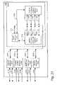
- FIG. 3depicts a remote control unit 1000 coupled 1002 to set-top apparatus 1100 , communicating via a two-stage wireline communications system containing a wireline physical transport 1200 through a distributor node 1300 , and through a high speed physical transport 1400 , possessing various delivery points 1510 and entry points 1512 – 1518 to a tightly coupled server farm 3000 , with one or more gateways 3100 , and one or more tightly coupled server arrays 3200 , in accordance the invention;
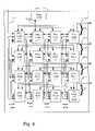
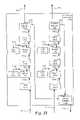
- FIG. 4depicts a coupled server array 3200 of FIG. 3 ;
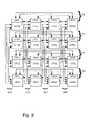
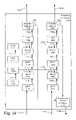
- FIG. 5depicts a gateway 3100 of FIG. 3 ;
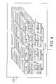
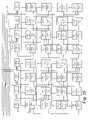
- FIG. 9depicts a simplified block diagram using an array of processors as shown as 3200 in FIG. 3 ;
- FIG. 10depicts a flowchart of a method using a back channel from a multiplicity of user sites containing a multiplicity of identified speech channels presented to a speech processing system at a wireline node in a network supporting cable television delivery in accordance with the invention
- FIG. 11Adepicts a detail flowchart of operation 2012 of FIG. 10 further partitioning of the received back channel
- FIG. 11Bdepicts a detail flowchart of operation 2022 of FIG. 10 further processing the multiplicity of the received identified speech channels;
- FIG. 11Cdepicts a detail flowchart of operation 2032 of FIG. 10 further responding to the identified speech content
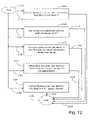
- FIG. 12depicts a detail flowchart of operation 2000 of FIG. 10 further performing the method using the back channel from multiple user sites;
- FIG. 13Adepicts a detail flowchart of operation 2112 of FIG. 11C further responding to the identified speech content
- FIG. 13Bdepicts a detail flowchart of operation 2112 of FIG. 11C further responding to the speech content
- FIG. 14depicts a detail flowchart of operation 2112 of FIG. 11C further responding to the identified speech content from the associated user site;
- FIG. 15Adepicts a detail flowchart of operation 2112 of FIG. 11C further responding to the identified speech content from the associated user site;
- FIG. 15Bdepicts a detail flowchart of operation 2252 of FIG. 15A identifying the user
- FIG. 16depicts a detail flowchart of operation 2112 of FIG. 11C further responding to the identified speech content from the associated user site;
- FIG. 17Adepicts the speech content response 2350 including current response menu 2352 and cumulative user site response 2354 in accordance with the invention
- FIG. 17Bdepicts a detail flowchart of operation 2112 of FIG. 11C further responding to the identified speech content from the associated user site;
- FIG. 18Adepicts a detail flowchart of operation 2112 of FIG. 11C further responding to the identified speech content from the associated user site;
- FIG. 18Bdepicts a detail flowchart of operation 2092 of FIG. 11B further processing the multiplicity of the received speech channels;
- FIG. 19Adepicts a simplified block diagram of a hand held remote 1000 , containing microphone 1060 and keypad 1020 supporting user input which is organized and processed by embedded controller 1050 for communication by wireless interface 1040 coupled 1002 to set-top apparatus 1100 , as shown in FIG. 3 ;
- FIG. 19Bdepicts a simplified block diagram of set-top apparatus 1100 as shown in FIG. 3 showing coupling 1002 and first wireline physical transport 1200 further comprised of downlink coupling 1202 and uplink coupling 1204 ;
- FIG. 19Cfurther depicts set-top apparatus 1100 as shown in FIG. 19B containing a set-top appliance 1120 coupled 1002 with hand held remote 1000 and coupled 1112 with set-top box 1120 possessing downlink coupling 1202 and uplink coupling 1204 ;
- FIG. 19Dfurther depicts set-top apparatus 1100 as shown in FIG. 19B containing a set-top appliance 1120 coupled 1002 with hand held remote 1000 and possessing downlink coupling 1202 and uplink coupling 1204 as well as providing processed downlink coupling 1114 to set-top box 1110 and receiving initial uplink coupling 1112 from set-top box 1110 ;
- FIG. 20Adepicts a simplified block diagram of set-top appliance 1120 as shown in FIG. 19C supporting coupling 1002 with hand held remote 1000 and coupling 1112 with set-top box 1110 ;
- FIG. 20Bdepicts a simplified block diagram of set-top appliance 1120 as shown in FIG. 19D supporting coupling 1002 with hand held remote 1000 and couplings 1112 and 1114 with set-top box 1110 ;
- FIG. 20Cdepicts a block diagram further depicting accessibly coupled 1162 memory 1160 as shown in FIGS. 20A and 20B ;
- FIG. 21depicts a remote control unit 1000 - 180 coupled 1002 - 180 to set-top apparatus 1100 - 180 , communicating via a two-stage wireline communications system containing a wireline physical transport 1200 through an augmented distributor node 1310 interfacing to a wireline communications loop including an augmented Headend 1410 further supporting a communications loop including augmented metropolitan Headend 1410 , in accordance with the invention;
- FIG. 22depicts a remote control unit 1000 - 180 coupled 1002 - 180 to set-top apparatus 1100 - 180 , communicating via a two-stage wireline communications system containing a wireline physical transport 1200 through a distributor node 126 interfacing to a wireline communications loop including an augmented Headend 1414 further supporting a communications loop including augmented metropolitan Headend 1410 , in accordance with the invention;
- FIG. 23depicts a detail block diagram of an augmented distributor node 1310 , coupled to wireline physical transport 1200 and coupled to the wireline communications loop of FIG. 21 ;
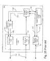
- FIG. 24depicts an alternative detail block diagram of an augmented distributor node 1310 , coupled to wireline physical transport 1200 and coupled to the wireline communications loop of FIG. 21 ;
- FIG. 25depicts a generic block diagram of a prior art Headend 104 as shown in FIG. 3 ;
- FIG. 26depicts an augmented Headend 1410 of FIG. 21 or an augmented Headend 1414 of FIG. 22 or an augmented metropolitan Headend 1410 of FIGS. 21 or 22 , in accordance with the invention
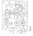
- FIG. 27depicts an alternative augmented Headend 1410 of FIG. 21 or an alternative augmented Headend 1414 of FIG. 22 or an alternative augmented metropolitan Headend 1410 of FIGS. 21 or 22 , in accordance with the invention
- FIG. 28Adepicts a block diagram of a speech engine 1330 as shown in FIG. 23 ;
- FIG. 28Bdepicts a block diagram of a speech engine 1330 as shown in FIG. 24 ;
- FIG. 29depicts a more detailed block diagram of a speech engine 1330 as shown in FIG. 28A ;
- FIG. 30depicts an alternative detailed block diagram of a speech engine 1330 as shown in FIG. 28A ;
- FIG. 31depicts a second alternative detailed block diagram of a speech engine 1330 as shown in FIG. 28A ;
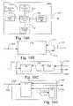
- FIG. 32Adepicts a block diagram of modulator engine 1350 of FIGS. 23 and 24 , and modulator engine 1450 of FIGS. 26 and 27 ;
- FIG. 32Bdepicts a block diagram of a local oscillator as is known in the art for use as a local oscillator depicted in FIGS. 33 and 34 as LO 1 1760 , LO 1 1860 , LO 2 1770 or LO 2 1870 ;
- FIG. 33depicts a detail block diagram of frequency conversion circuitry 1710 of FIG. 32A ;
- FIG. 34depicts an alternative detail block diagram of frequency conversion circuitry 1710 of FIG. 32A ;
- FIG. 35depicts a detailed diagram of speech engine 1330 as shown in FIG. 23 or speech engine 1430 as shown in FIG. 27 containing two plex communications grids with dual, redundant gateways.
- FIG. 3depicts a remote control unit 1000 coupled 1002 to set-top apparatus 1100 .
- Set-top apparatus 1100communicates via a two-stage wireline communications system containing a wireline physical transport 1200 to a distributor node 1300 .
- Set-top apparatus 1100communicates through distributor node 1300 across a high-speed physical transport 1400 to a tightly coupled server farm 3000 , possessing various delivery points 1510 and entry points 1512 – 1518 .
- Tightly coupled server farm 3000contains one or more gateways 3100 , and one or more tightly coupled server arrays 3200 .
- a server farmrefers to a collection of at least two server components communicatively coupled to one another.
- the server componentsmay or may not all be directly communicatively coupled to each other.
- a server componentrefers to at least a gateway, server array, server computer, database engine, or disk farm.
- gatewayrefers to at least one of the following: A gateway may perform protocol conversion between different types of networks or applications; gateways may support complete conversion of one protocol to another, or support one protocol from within another protocol; a gateway may perform conversion between two messaging or mail protocols; a gateway may act as a go-between for two networks with similar protocols, providing an entry/exit point for one network in the other network.
- gatewaysinclude proxy servers; a gateway may switch speech and data between a terrestrial network and an orbiting satellite communications system; and a gateway may perform network layer switching tasks between at least two networks, coordinating the delivery of information, usually in the form of messages, packets or data streams to various destinations in the networks.
- a server arrayrefers to a multi-dimensional lattice or array of server computers, each with an associated multi-dimensional array address, and a communication grid supporting communication between server computers based upon the multi-dimensional array addresses of the source and destination server computers.
- a tightly coupled server arrayis a server array possessing a very low latency communication grid.
- the inventionmay include a remote control unit 1000 fitted with a microphone.
- Remote control unit 1000may be fitted with such features as a special noise canceling microphone and/or a push-to-talk button.
- the microphone in the remoterelays the subscriber's speech commands to the central speech recognition engine.
- the push-to-talk buttonmay begin the process of speech recognition by informing the system that the subscriber is about to speak and also to provide immediate address information. Address information identifies the user site at which the speaking occurs.
- the inventionmay also include an array of microphones that are operated in conjunction with a remote control 1000 that is coupled to the set top box 1100 .
- the microphone arraymay further provide an echo-canceling capability in receiving speech signals within the area of usage.
- each remote control unit 1000may be more than one remote control unit 1000 with one or more microphones, each remote control unit under the control of a distinct, identified user. Such situations are particularly useful in game playing settings, where different users may wish to make commands to the game simulation like “arm the photon torpedoes”, etc.
- a given residencemay include more than one set-top box 1100 , each of which has a distinct address in the network delivering video content and/or cable television. Each constitutes a distinct user site and may be parameterized differently.
- a first set-top box in a recreation area for childrenmay allow identified users, who are children, to select programming on only certain channels.
- a second set-top box in a private area of adults, such as a parental bedroommay be parameterized so that child identifier users have no privileges.
- Speech commands from the subscribermay be preprocessed.
- the analog signals picked up from the microphoneare converted to digital signals where they undergo additional processing before being transmitted to the speech recognition and identification engine located in the cable Headend or other centralized location.
- Such speech preprocessingmay include encryption, compression, or conversion to an alternative form of speech representation.
- Coupling 1002may use a wireline or wireless physical transport. Coupling 1002 may use a wireless transport, including, but not limited to, at least one of the infra-red, microwave, or radio frequency spectrum, as well as ultrasonic signaling. Coupling 1002 may support bi-directional communication between remote control 1000 and set-top box or appliance 1100 . The communication may be predominantly or strictly from remote control 1000 to set-top box or appliance 1100 .
- the speech signal from the remote 1000may be a digitally modulated RF signal whose properties may comply with Part 15 of the FCC rules.
- the set-top box 1100or set-top appliance 1100 , receives the speech signal from the remote 1000 and performs the preprocessing function mentioned above.
- the set-top box 1100may also be used to transmit speech and subscriber address data to the centralized location or Headend for speech recognition and identification.
- the Radio Frequency (RF) signal from the remote 1000is received by the set-top appliance 1100 and then remodulated for upstream transmission 1200 on the 5 to 40 MHz cable return path. If a commercial set-top box 1100 is used to transmit the upstream speech data, then the upstream channel allocation and transmission protocol are controlled by the bi-directional communication system which is resident in the set-top box.
- RFRadio Frequency
- a commercial set-top box 1100may not be used to transmit the digitized speech data upstream.
- the set-top appliance 1100is then responsible for receiving the upstream channel allocation and synchronization information.
- the data receiver in the set-top appliance 1100can be tuned to any one of several downstream data channels to receive channel and synchronization information.
- the set-top appliance 1100is also capable of receiving and decoding data in the downstream path. This function is required to organize and synchronize the transmission of upstream data which may include user feedback. Downstream data can contain upstream channel allocation information and speech verification overlay information coded as text.
- the set-top box 1100may be used for both upstream and downstream communication for the described speech command function.
- the function of the set-top appliance 1100may be to receive the RF signal from the remote control and then digitize and compress the speech signal and prepare it for upstream transmission.
- New RF protocol standardssuch as Blue Tooth, allow the remote control's RF signal to transmit the speech signal directly to the set-top box where again, the preprocessing can either be done in the remote control 1000 or executed from firmware within the set-top box 1100 .
- infra-red signalingmay be employed to transmit the speech signal to the set-top box.
- Set-top boxes 1100that employ the DOCSIS type cable modems such as Open Cable set-top boxes or the so called Heavy Set-top boxes from such companies as Scientific Atlanta and General Instruments are capable of sending and receiving speech data using efficient data transmission protocols.
- the DOCSIS protocolalso incorporates error detection and correction capabilities as well as other transmission enhancements such as pre-equalization for more efficient and error free transmission.
- FIG. 4depicts a coupled server array 3200 of FIG. 3 .
- FIG. 5depicts a gateway 3100 of FIG. 3 .
- the systemuses the subscriber's address information as a mechanism by which the centrally located AgileTVTM Speech Processor can fetch a particular subscriber's parameter file.
- the parameter filecontains speech training parameter data, speech identification parameters and user profiles for each user at that address. This file can also contain parental control information in a residential setting and other specifics for that particular address, such as language preferences or movie preferences or even internet preferences.
- the Addressed Subscriber Parameter Filegives the system an extremely high probability of speech recognition and user identification.
- Such addressingsupports secure transactions such as banking because the speech recognition and identification system has to only identify a few parameter files for any one physical address, resulting in a very high probability of recognizing a specific speaker's speech.
- Financial transaction securitye.g. speech banking and e-commerce
- Thisdirectly supports a method of contracting based upon an offer presented to the user by the system, and a recognizable acceptance of the offer by the identified user.
- the method of contractingmay further include storing the offer and acceptance as a recording mechanism for the contract.
- a central locationmay include a node, Headend, or metropolitan Headend for a residential broadband network.
- the return path receiving equipment in the central locationmay be specific to that type of box. Therefore, the data coming from this equipment, which contain other upstream traffic, may be parsed in such a way that only the speech commands and address information from the subscriber are input to the speech recognition engine in the central location.
- the upstream data receiver in the central locationmay be a separate unit that receives only speech command signals from set-top appliances at the user sites.
- the set-top applianceas the upstream transmitter allows the use of custom upstream protocols such as FM, AM, PSK, or spread spectrum digital transmission. Digital transmission techniques such as QPSK or QAM can also be employed.
- the received upstream signalmay be in the form of a data stream containing speech and address information.
- the data stream containing speech and address informationmay be Ethernet compatible.
- the AgileTVTM Voice Processing UnitAVPU
- the digital speech signals from each of these nodesmay be combined in the AVPU input multiplexer. The combining of digital speech signals may result in a smaller number of high speed digital streams.
- Upstream signals such as 1510are received at the gateway 3100 .
- Speech and data signalsmay be received from commercial return path data receivers. Speech and data signals are also received and decoded by custom return path receivers using at least one of the following protocol options: FM or AM modulation/demodulation, FDMA, TDMA, FSK, PSK, or QPSK digital modulation/demodulation, Spread Spectrum modulation/demodulation, Telephony, cellular return, or Wireless.
- the AVPU Enginemay not be an application service, in and of itself.
- the systemmay provide new end user applications.
- the AVPU Enginemay provide speech recognition and control services for existing applications, such as Interactive Program Guides, Video On Demand (VOD) services or access to the Internet or World Wide Web.
- VODVideo On Demand
- applicationssuch as Video On Demand or Interactive Program Guides, that request service access with the speech recognition services may be required first to register with the AVPU system.
- At least one standard program interfacemay then be used to enable each application to specify its complete menu hierarchy.
- the inventionmay use exactly one standard program interface to enable applications to specify their complete menu hierarchy.
- a list structurespecifies each application's menu hierarchy. This list structure may be a tree. It contains labels for each menu, along with the text of each button on each menu screen, information the system needs to provide speech navigation services independently through the menu hierarchy on behalf of the application. This menu hierarchy represents the static portion of the application's data.
- the applicationmay inform the system of dynamic content, for example the names of movies in a Video On Demand system or of program names and times in an interactive program guide.
- the applicationmay inform the speech system of this context by passing a handle associated with the list of names that comprise the dynamic content.
- the speech systemmay combine the static menu content with the augmented dynamic content (see Similarity Searching below), to form a complete grammar.
- application-independent keywordssuch as HELP, may be combined with the static menu content and augmented dynamic content to form the complete grammar. This construct may then be passed to the speech system to maximize recognition accuracy.
- applicationsmay be required to inform the system whenever the content changes.
- the applicationregisters a new set of dynamic content every one-half hour. For a VOD system, this registration may be performed whenever the database of offered movies changes.
- recognition of a spoken requestmay cause a signal to be sent back to the application.
- This signalinforms the application to perform the requested action, and/or to update the contents of the screen as a result of the user's request.
- the applicationcan use the system's speech recognition services with minimal modifications to the application's code, while retaining the same graphical look and feel to which users have become accustomed.
- a speech-enabled remote controlmay be employed, e.g. containing a microphone, as well as traditional universal remote control functionality.
- the remote controlmay further contain a Push-To-Talk (PTT) button.
- PTTPush-To-Talk
- Conventional remote control functionsare transmitted via infra-red (IR).
- IRinfra-red
- the speech outputmay be wirelessly transmitted to a set top pod, module, or appliance located at the set-top box.
- the wireless transmission from the remote controlmay employ an electromagnetic physical transport layer or ultrasonic physical transport layer.
- the electromagnetic physical transport layermay use a radio frequency carrier or an infra-red carrier.
- the remote controlWhen the PTT button is pushed by the user, the remote control sends a PTT active command to the set top appliance.
- the appliancemay then inform the set-top box to place an icon on the screen, or otherwise indicate to the user that the system is listening to them.
- the speechis digitized, compressed, and transmitted to the set top appliance.
- the set top appliancemay perform any or all of the following: encrypt the speech sample to provide security; add subscriber address information; add a message length code; add error control coding to the assembled information.
- the error control codingmay include a Cyclical Redundancy Code (CRC), enabling data transmission errors to be detected.
- CRCCyclical Redundancy Code
- the set top appliancemay transmit speech information to the set-top box, which then transmits it to the central location as a series of packets.
- the set top appliancemay directly transmit the speech stream to the central location itself. This may continue until the set top appliance receives a PTT Release from the remote, indicating end of speech. This information is also transmitted to the central location, signaling end of spoken request.
- Each individual consumer's interfacei.e. set-top box or set-top appliance, may have a unique address.
- the address of the individual consumer's interfacemay be determined during the manufacturing process. As speech packets are transmitted upstream, this address information may be appended to the speech packets. The address information enables rapid determination of the user site from which the speech sample is received. The address information may precede the speech packets. The address information improves the efficiency of at least some of the central location processing stages.
- Assignment of an input buffer address to the speech samplemay be based upon the user site address.
- This input buffercollects incoming speech packets until the final packet of a spoken request has been received.
- Recognition of the final speech packet receiptmay be encoded in that speech packet.
- Final speech packet receipt recognitionmay include a delay in speech of greater than a predetermined amount of time.
- the speech delay amountmay be one or more of at least the following: a globally defined constant, a user site defined constant, an identified user defined constant, or an application-defined constant for an application serviced by the speech recognition system.
- the final speech packetmay be generated based upon the release of the PTT button in the remote control unit.
- the final speech packetmay be generated at the remote control unit, set top pod, set top appliance, set top box, node, Headend or metropolitan Headend, or by the serviced application.
- the final speech packetmay be generated by the serviced application based upon a time schedule, e.g. a fixed period in which participants may respond, a privilege scheme, and/or other application related scheme.
- CRCCyclical Redundancy Code
- the speech input processormay use the sample's source address identifying a user site to target the speech data to a specific speech processing processor.
- This direct correspondence between the source address and a specific speech processorallows speech processors to cache user-specific parameters for the user sites they serve.
- the mapping of source addresses to speech processorreduces the bandwidth necessary to move user site-specific data to each speech processor.
- a translation tablemay be used to allow speech to processor assignments to be changed dynamically in the event of a hardware or other failure, e.g. capacity overload, while retaining the efficiency advantages of directly mapping the speech channel to the processor.
- a grammaris a structure often containing the words which are most likely to be spoken, the order in which these words may appear, and the meaning of various sequences of words. This structure may be a hardware configuration, software program, data structure, or a combination of two or more of these.
- the grammar associated with the speech sampleis transferred to the target speech processor.
- the grammar transfermay use a simple Least Recently Used (LRU) queue. If the speech processor contains enough empty space in its memory, then the indicated grammar is transferred directly to the empty memory from mass storage. Mass storage may include, but is not limited to, a disk, disk farm, or Redundant Array of Independent Disks (RAID), a high bandwidth disk farm. If not, then the least-recently-used grammar entry may be discarded, and the new grammar information loaded into the vacated memory.
- LRULeast Recently Used
- the next step in processing the speech sampleensures that the current parameters associated with this user site are already cached in the specific speech processor's RAM. If these parameters are not present, then the least-recently-used parameter cache entry may be evicted from the cache.
- the oldest cache entry on this speech processoris first examined to see if it has been modified. If it has, the cache entry is stored to mass storage, and the cache slot is then declared vacant. Next, the user site speech parameters associated with the new speech sample are loaded into the vacated cache block. During the relatively long access times needed to load a new set of user site parameters from mass storage (and optionally to write the old parameters to the disk, etc.), the current speech sample may be held in the input buffer in a waiting state.
- the speech sampleis moved into the work queue for the speech processor. This minimizes speech processor delay for processing other speech requests during disk accesses. Instead, the speech processor may process other speech samples associated with user sites whose parameters are already in the cache.
- the speech samplemay be assigned to the speech processor by placing a description of the speech sample into the target speech processor's work queue. As speech samples are processed, they may be removed from the front of the work queue by the speech processor.
- the speech processorreaches the current input sample.
- the speech sampleis transferred into the speech processor's local memory, and the status of this speech sample changed to Next. This transfer may occur in parallel with the processing of the prior speech sample, ensuring that speech processor utilization is maximized.
- the total number of speech samples sitting in the waiting and working queues of a speech processorpreferably should not exceed the number of cache entries in the speech processor.
- the first step in recognizing the current speech samplemay determine which individual person pronounced the current spoken request.
- the Speaker Identification software module running on the targeted speech processorcompares the spoken characteristics of this speech sample with the characteristics of the speakers who have been previously identified in this user site.
- the incoming speech samplematches the characteristics of a previously identified speaker. When this occurs, the speech sample is passed on to the next phase, speech recognition.
- a new user routineis invoked, enabling a new user to be associated with this household.
- This routinerecords the new individual's speech parameters into this user site's speech parameters, so that the new speaker may be identified during subsequent spoken requests.
- the systemmay offer the user site manager the opportunity to erase or modify the new speaker parameters.
- the inputs to the speech recognition software modulemay include a speech sample, an individual user's speech parameters, and the grammar to be recognized.
- the speech enginedetermines the most likely spoken request based on statistical analysis, and may return a text string corresponding to the spoken request. This matching process is probabilistic: along with the returned text string, the speech engine may also return a confidence measure, or percentage of match likelihood.
- the returned text string and confidence measureenables different applications to respond differently based on the calculated confidence in the recognition result.
- recognition results having a low cost to the usersuch as a request to display listings for a particular movie
- lower confidence criteriamay be applied.
- recognition results with a high cost to the usersuch as a request to purchase a movie
- higher confidence thresholdsmay be required.
- purchase verificationmay be requested.
- the speech recognition enginemay determine partial matches to more than one possible phrase, returning the text of several possible matches. This process enables an application or user to select from several alternative recognition results.
- the systemmay record the speech sample representing the purchase request onto mass storage.
- This speech sample recordingis performed to provide verification that a purchase request was made, should a user dispute their intent to purchase. This further supports speech-based methods of contracting.
- the recordingmay be compressed in either a standard or non-standard manner, which may further include encryption technology.
- This rapid visual feedbackmay be accomplished by transmitting the recognized text string back to the set-top box.
- Software executing within the set-top boxdisplays the text information in a special window on top or overlaying of the existing application display.
- software executing within the set-top boxmay select an alternative feedback display, for example, a different channel containing a background field, and displays the overlay information on top of this background.
- this overlay display capabilitymay be used to help refine the user's query. By displaying the text of the possible recognition results, the user can easily select from the returned list.
- the usermay elect to start again. However, more commonly, one of the displayed strings match, or be likely to readily lead to the user's speech request with appropriate modification. When this is the case, the user can readily select from the displayed alternatives, enabling improved productivity in low-recognition situations.
- Similarity searchingWhen the system is scanning for dynamic content, i.e. movie titles and actor names, a similarity search feature may be available. This enables searches for names which are only partially matched, or which resemble the recognized phrase, without requiring precise specification of the exact title or name.
- the technique used to deliver similarity searchingis to augment the dynamic content list specified by the application. Words similar in meaning, content, or spelling to words in the content list may be automatically added to the dynamic content list whenever the application informs the system of a content update. This enables the recognition grammar to be extended to support a broader array of matches without requiring bandwidth-intensive text searches each time a user's speech request has been received. Links between similar and target words may be maintained in the internal representation of the grammar, thereby providing direct access to target names. This further enhances system performance.
- similarity databasesmay be constructed from at least one or more of the following database architectures: relational, SQL, knowledge-based, inferential knowledge bases including Horn clause and extended Horn clause fact bases, fuzzy versions of the above, as well as neural networks and combinations of these techniques. Also, manual additions may be made at the AgileTVTM central office.
- the entire systemmay provide fault tolerance for robust performance.
- the systemmay automatically recognize most component failures, and disable faulty processors.
- AVPUVoice Processing Unit
- the systemmay also communicate continuously with a network operations center, enabling rapid identification of system errors, as well as rapid service dispatch to correct any problems.
- a speech command preprocessormay perform the function of speech filtering, digitizing, data compression, encoding pauses in speech, and address insertion. Preprocessing speech commands at user sites results in a lower upstream data rate. This processing can be located in the remote 1000 , the Set-top appliance 1100 , or the set top box.
- a Speech Packet Processormay be centrally located in or near a wireline node specifically to capture and prepare the upstream speech packets that are to be fed to the Speech Recognition Engine.
- a speech processor systemmay be centrally located in or near a wireline node, which may include a Cable Television (CATV) central location.
- the speech recognition systemmay be centrally located in or near a server farm.
- the speech recognition systemmay be centrally located in or near a web-site hosting location.
- the speech recognition systemmay be centrally located in or near a gateway.
- CATVCable Television
- the speech recognition engineprocesses speech packets to create speech content and formulate the response to the speech content for each of the user sites.
- the systemalso performs address decoding for routing and latency reduction. It also performs the function of decoding the pauses between words or sounds originally encoded on the preprocessor at the user site.
- a method for a very high level of securitybased on the ability of being able to precisely recognize a parent's speech or a child's speech based on a limited subset of choices.
- the ability to recognize an individual speaker with a very high probability of identifying the specific speakeris based on knowing the address of the user site.
- a large capacity, centrally located, natural speech recognition enginecan readily identify a specific speaker from among a small set of choices, allowing a parent to voice print and therefore control the type, or amount or timing of content a child may request.
- a childmay be able to learn PIN numbers but cannot readily fool the voice print.
- Speaker recognitionis particularly appealing in this parental control application, and can be applied with very high accuracy, due to the limited number of speakers per user site. Parents may control the specific viewing times, total time, or content that a child can watch television through this system and its use.
- FIGS. 3–5The operational discussion just presented regarding FIGS. 3–5 is applicable to the relevant operational system embodiments based upon any and all of the FIGS. 19A to 24 , as well as, FIGS. 26 to 31 .
- a plex communications networkhas M orthogonal directions that support communications between an M dimensional lattice that may include N ⁇ M plex-nodes, where M is at least two and N is at least four.
- Each plex-node pencil in a first orthogonal directioncontains at least four plex-nodes and each plex-node pencil in a second orthogonal direction contains at least two plex-nodes.
- Each of the plex-nodescontains a multiplicity of ports.
- a plex-node pencilrefers to a 1-dimensional collection of plex-nodes differing from each other in only one dimensional component, i.e. the orthogonal direction of the pencil.
- a nodal pencil in the first orthogonal direction of a two-dimensional arraycontains the plex-nodes differing in only the first dimensional component.
- a nodal pencil in the second orthogonal direction of a two-dimensional arraycontains the plex-nodes differing in only the second dimensional component.
- the plex communications networkis comprised of a communication grid interconnecting the plex-nodes.
- the communications gridmay include N ⁇ (M ⁇ 1) communication pencils, for each of the M directions.
- Each of the communication pencils in each orthogonal directionis coupled with a corresponding plex-node pencil containing a multiplicity of plex-nodes coupling every pairing of plex-nodes of the corresponding plex-node pencil directly.
- Communication between two plex-nodes of a nodal pencil coupled with the corresponding communication pencilcomprises traversal of the physical transport layer(s) of the communication pencil.
- Such plex communications networkssupport direct communication between any two plex-nodes belonging to the same communication pencil. This supports communication between any two plex-nodes in at most M hops between plex-nodes.
- Plex-node 0,0is coupled 402 to communication pencil 4100 .
- Plex-node 1,0is coupled 404 to communication pencil 400 .
- Plex-node 2,0is coupled 406 to communication pencil 400 .
- Plex-node 3,0is coupled 408 to communication pencil 400 .
- Plex-node 0,1is coupled 412 to communication pencil 410 .
- Plex-node 1,1is coupled 414 to communication pencil 410 .
- Plex-node 2,1is coupled 416 to communication pencil 410 .
- Plex-node 3,1is coupled 418 to communication pencil 410 .
- Plex-node 0,2is coupled 422 to communication pencil 420 .
- Plex-node 1,2is coupled 424 to communication pencil 420 .
- Plex-node 2,2is coupled 426 to communication pencil 420 .
- Plex-node 3,2is coupled 428 to communication pencil 420 .
- Plex-node 0,3is coupled 432 to communication pencil 430 .
- Plex-node 1,3is coupled 434 to communication pencil 430 .
- Plex-node 2,3is coupled 436 to communication pencil 430 .
- Plex-node 3,3is coupled 438 to communication pencil 430 .
- each plex-nodeThree of these ports on each plex-node are devoted to providing a direct interconnect to the other plex-nodes of its row through a collection of communication paths forming the communication pencil in the second orthogonal direction. These plex-nodes belong to the same row as the plex-nodes of the plex-node pencil in the second orthogonal direction.
- a plex-nodemay have at least one additional port. At least one of the additional ports may be connected to an external network. Further, at least one of the additional ports may be connected to an external mass storage system. In other embodiments of the invention, at least one of the additional ports may be connected to an external database system.
- a plex-nodemay contain at least one instruction processor.
- an instruction processorincludes but is not limited to instruction set processors, inference engines and analog processors.
- An instruction set processorrefers to instruction processors changing state directly based upon an instruction, and which change an internal state by executing the instruction.
- the instructionmay include, but is not limited to, direct or native instructions and interpreted instructions.
- An inference enginechanges state when presented an instruction, which may include an assertion, an assumption, or an inference rule.
- Inference enginesinclude, but are not limited to, Horn clause engines such as Prolog requires, constraint based systems and neural network engines.
- analog processorsinclude, but are not limited to, optical signal processors, CCD's, and resonant cavity devices responding to data and/or controls asserted in the analog domain.
- Communicationincludes, but is not limited to, communication using a digital communications protocol. Communication also includes a messaging protocol using the digital communications protocol. Communications also includes a messaging protocol supporting TCP-IP, supporting the Internet, and/or supporting the World Wide Web.
- Communicationsmay also include at least one video stream protocol using a digital communications protocol.
- Communicationsmay include at least one multi-media stream protocol using the video stream protocols including motion JPEG and/or at least one form of MPEG.
- the inventionmay support Wavelength Division Multiplex (WDM) through the physical transport of the communication paths of the communication pencils.
- WDMWavelength Division Multiplex
- Each plex-nodemay include a communication processor.
- Each plex-nodemay further include M communications processors.
- the ports of each communications processormay be connected to each one of the pencils supporting pencil communications processing.
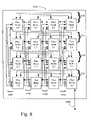
- upstream signals 1510may be received at the Plex-node 0,0, performing functions similar in nature to processor node 3110 of FIGS. 3 , 4 and 5 .
- Plex-node 0,1may couple 3142 to RAID 3130 subsystem, providing high-speed access to a high capacity disk farm.
- Various signals 1512 to 1518may be generated by various plex-nodes. Note that because of the uniformity of the communication structure, there is great flexibility in choosing which plex-node generates which communication signals.
- FIG. 7also shows coupling 3002 to a speech recognition server array 3200 .
- Each plex-node of FIG. 8may include a plex communications network supporting a two or more dimensional array of internal plex-nodes, each including at least one instruction processor.
- FIG. 9depicts a simplified block diagram using an array of processors as shown as 3200 in FIG. 3 .
- Each CPUmay possess three or more high speed serial protocol channels C 1 - 3 , a high speed interconnect bus B 1 , a low speed interconnect bus PCI and a local memory access bus R.
- Each CPUmay include at least two processors.
- Each processormay be an instruction processor.
- Each CPUmay be an integrated circuit.
- the integrated circuitmay be a BCM12500 manufactured by Broadcom Corporation of Irvine, Calif.
- CPU 1 and CPU 2are locally coupled via at least one of the interconnect buses. Each CPU possesses locally accessible memory via an R bus. Each CPU may further access locally accessible memory via its own R bus.
- the R bus accessed memorymay include DDR SDRAM (Double Data Rate Synchronous DRAM).
- Three serial protocol channels for the first CPU of each CPU pairare dedicated to communication within each row of CPU pairs.
- Three serial protocol channels for the second CPU of each CPU pairare dedicated to communication within each column of CPU pairs.
- each CPUcontains at least two processors. Assume each processor is operating at K billion integer operations/second and L billion floating point operations/second. Assume the high speed serial channels support a gigabit/second bidirectional transfer rates. The DDR DRAMs support M gigabyte/second access rates. This system provides 64*K billion integer operations, 64*L billion floating point operations, 128 gigabits/second interconnect communication bandwidth throughout the array through the high speed serial channels, as well as 64*M gigabytes/second local memory access. By decoupling the tasks running on each processor, making them independent and concurrent, this system architecture achieves the dream of Multiple-Instruction Multiple Datapath computing (MIMD), providing essentially linear speed up with the increase in processors for up to 64 processors.
- MIMDMultiple-Instruction Multiple Datapath computing
- Such architecturescan support each processor generating a frame in a local frame buffer and rendering it into a motion video stream, which is merged into a multiplexed video content stream suitable for a variety of multi-media applications.
- This apparatusmeets or exceeds the requirements of a number of teraflop-class computing applications, which today have no cost effective solution.
- the processorsmay each be dual instruction processors housed in a single package.
- Each of these arrayswill process over 1K speakers concurrently and fit into a single rack mount enclosure. Standard 72 inch, tall racks could then hold 4 such speech engines, also known herein as an AVPU, supporting up to 140,000 subscribers.
- Each servercontains at least dual, redundant, hot-swappable power supplies, and redundant, hot-swappable disks with automatic recovery for failed disk drives.
- the hot-swappable power suppliesmay further be half-sized, each supporting the power requirements of half the server engine.
- FIG. 10depicts a flowchart of a method that uses a back channel containing a multiplicity of identified speech channels for speech recognition at a wireline node in a network supporting video or cable television delivery in accordance with the invention.
- the back channelis from a multiplicity of user sites and is presented to a speech processing system at the wireline node in the network.
- the speech processing systemperforms the operations of the method.
- Operation 2000starts the operations of this flowchart.
- Arrow 2002directs the flow of execution from operation 2000 to operation 2004 .
- Operation 2004performs receiving the back channel to create a received back channel.
- Arrow 2006directs execution from operation 2004 to operation 2008 .
- Operation 2008terminates the operations of this flowchart.
- Arrow 2010directs the flow of execution from starting operation 2000 to operation 2012 .
- Operation 2012performs partitioning the received back channel into a multiplicity of received identified speech channels.
- Arrow 2014directs execution from operation 2012 to operation 2008 .
- Operation 2008terminates the operations of this flowchart.
- Arrow 2020directs the flow of execution from starting operation 2000 to operation 2022 .
- Operation 2022performs processing the multiplicity of the received identified speech channels to create a multiplicity of identified speech content.
- Arrow 2024directs execution from operation 2022 to operation 2008 .
- Operation 2008terminates the operations of this flowchart.
- Arrow 2030directs the flow of execution from starting operation 2000 to operation 2032 .
- Operation 2032performs responding to the identified speech content to create an identified speech content response, for each of the multiplicity of the identified speech contents.
- Arrow 2034directs execution from operation 2032 to operation 2008 .
- Operation 2008terminates the operations of this flowchart.
- Portions of the flowchart of FIG. 10 related to operations 2022 and 2032may operate a speech processing system coupled to a wireline node in a network.
- the wireline nodeprovides multiple received identified speech channels to the speech processing system.
- the received identified speech channelsare based upon a received back channel at the wireline node from multiple user sites coupled to the network.
- the networksupports video delivery to the user sites and/or cable television delivery to the user sites.
- the speech processing systemmay include at least one computer.
- Operations 2022 and 2032may be implemented as program steps of a program system operating at least part of the computers included in the speech processing system. Implementations of these operations as program steps may reside in memory accessibly coupled to at least one computer in the speech processing system.
- operations 2002 and 2012may be implemented in hardware and/or implemented as program steps used in operating computers located at the wireline node. Such computers may or may not be part of the speech processing system.
- At least one, and possibly all, of the identified speech channelsmay have an associated user site.
- FIG. 11Adepicts a detail flowchart of operation 2012 of FIG. 10 further partitioning the received back channel.
- Arrow 2070directs the flow of execution from starting operation 2012 to operation 2072 .
- Operation 2072performs partitioning the received back channel into a multiplicity of received identified speech channels from the associated user site.
- Arrow 2074directs execution from operation 2072 to operation 2076 .
- Operation 2076terminates the operations of this flowchart.
- FIG. 11Bdepicts a detail flowchart of operation 2022 of FIG. 10 further processing the multiplicity of the received identified speech channels.
- Arrow 2090directs the flow of execution from starting operation 2022 to operation 2092 .
- Operation 2092performs processing the multiplicity of the received identified speech channels from the associated user site to create multiple identified speech contents.
- Arrow 2094directs execution from operation 2092 to operation 2096 .
- Operation 2096terminates the operations of this flowchart.
- FIG. 11Cdepicts a detail flowchart of operation 2032 of FIG. 10 further responding to the identified speech content.
- Arrow 2110directs the flow of execution from starting operation 2032 to operation 2112 .
- Operation 2112performs responding to the identified speech content from the associated user site to create the identified speech content response for the associated user site.
- Arrow 2114directs execution from operation 2112 to operation 2116 .
- Operation 2116terminates the operations of this flowchart.
- FIG. 12depicts a detail flowchart of operation 2000 of FIG. 10 further performing the method using the back channel from multiple user sites.
- Arrow 2120directs the flow of execution from starting operation 2000 to operation 2122 .
- Operation 2122performs determining the associated user site from the received identified speech channel.
- Arrow 2124directs execution from operation 2122 to operation 2126 .
- Operation 2126terminates the operations of this flowchart.
- Arrow 2130directs the flow of execution from starting operation 2000 to operation 2132 .
- Operation 2132performs determining the associated user site from the identified speech content.
- Arrow 2134directs execution from operation 2132 to operation 2126 .
- Operation 2126terminates the operations of this flowchart.
- Arrow 2140directs the flow of execution from starting operation 2000 to operation 2142 .
- Operation 2142performs determining the associated user site from the identified speech content and a speaker identification library.
- Arrow 2144directs execution from operation 2142 to operation 2126 .
- Operation 2126terminates the operations of this flowchart.
- Arrow 2150directs the flow of execution from starting operation 2000 to operation 2152 .
- Operation 2152performs determining the associated user site from the identified speech content and a speech recognition library.
- Arrow 2154directs execution from operation 2152 to operation 2126 .
- Operation 2126terminates the operations of this flowchart.
- Arrow 2160directs the flow of execution from starting operation 2000 to operation 2162 .
- Operation 2162performs determining the associated user site from an identification within the speech channel.
- Arrow 2164directs execution from operation 2162 to operation 2126 .
- Operation 2126terminates the operations of this flowchart.
- the determination of the associated user sitemay be provided by an identification within the speech channel.
- a technicianmay be recognizable at many user sites, and may identify the user site as Room 432 or 10 Main Street in the process of activities at that user site.
- the inventioncan include at least one of the operations 2120 , 2132 , 2142 , 2152 and 2162 .
- FIG. 13Adepicts a detail flowchart of operation 2112 of FIG. 11C further responding to identified speech contents.
- Arrow 2170directs the flow of execution from starting operation 2112 to operation 2172 .
- Operation 2172performs processing the identified speech content response to create the identified user site response.
- Arrow 2174directs execution from operation 2172 to operation 2176 .
- Operation 2176performs sending the identified user site response to the identified user site.
- Arrow 2178directs execution from operation 2176 to operation 2180 .
- Operation 2180terminates the operations of this flowchart.
- FIG. 13Bdepicts a detail flowchart of operation 2112 of FIG. 11C further responding to the identified speech content.
- Arrow 2190directs the flow of execution from starting operation 2112 to operation 2192 .
- Operation 2192performs assessing the speech content response identified as to the user site to create a financial consequence identified as to the user site.
- Arrow 2194directs execution from operation 2192 to operation 2196 .
- Operation 2196performs billing the user site based upon the financial consequence.
- Arrow 2198directs execution from operation 2196 to operation 2200 .
- Operation 2200terminates the operations of this flowchart.
- FIG. 14depicts a detail flowchart of operation 2112 of FIG. 11C further responding to the identified speech content from the associated user site.
- Arrow 2210directs the flow of execution from starting operation 2112 to operation 2212 .
- Operation 2212performs assessing the speech response to create a financial consequence identified as to the user site.
- Arrow 2214directs execution from operation 2212 to operation 2216 .
- Operation 2216performs displaying the financial consequence to create a displayed financial consequence at the user site.
- Arrow 2218directs execution from operation 2216 to operation 2220 .
- Operation 2220performs confirming the displayed financial consequence from the user site to create a financial commitment.
- Arrow 2222directs execution from operation 2220 to operation 2224 .
- Operation 2224performs billing the user site based upon the financial commitment.
- Arrow 2226directs execution from operation 2224 to operation 2228 .
- Operation 2228terminates the operations of this flowchart.
- FIG. 15Adepicts a detail flowchart of operation 2112 of FIG. 11C further responding to the identified speech content from the associated user site.
- Arrow 2250directs the flow of execution from starting operation 2112 to operation 2252 .
- Operation 2252performs identifying a user based upon the speech content identified with the user site to create an identified user.
- Arrow 2254directs execution from operation 2252 to operation 2256 .
- Operation 2256terminates the operations of this flowchart.
- FIG. 15Bdepicts a detail flowchart of operation 2252 of FIG. 15A further identifying the user.
- Arrow 2270directs the flow of execution from starting operation 2252 to operation 2272 .
- Operation 2272performs fetching a user profile list based upon the user site and the user profile list containing at least one user profile.
- Arrow 2274directs execution from operation 2272 to operation 2276 .
- Operation 2276performs identifying the user based upon the speech content and based upon the user profile list to create an identified user.
- Arrow 2278directs execution from operation 2276 to operation 2280 .
- Operation 2280terminates the operations of this flowchart.
- FIG. 16depicts a detail flowchart of operation 2112 of FIG. 11C further responding to the identified speech content from the associated user site.
- Arrow 2290directs the flow of execution from starting operation 2112 to operation 2292 .
- Operation 2292performs assessing the speech response based upon the identified user to create a financial consequence for the identified user.
- Arrow 2294directs execution from operation 2292 to operation 2296 .
- Operation 2296performs displaying the financial consequence to create a displayed financial consequence at the user site.
- Arrow 2298directs execution from operation 2296 to operation 2300 .
- Operation 2300performs confirming the displayed financial consequence from the user site based upon the identified user to create a financial commitment.
- Arrow 2302directs execution from operation 2300 to operation 2304 .
- Operation 2304performs billing the identified user based upon the financial commitment.
- Arrow 2306directs execution from operation 2304 to operation 2308 .
- Operation 2308terminates the operations of this flowchart.
- FIG. 17Adepicts the speech content response 2350 , including the current response menu 2352 and the cumulative user site response 2354 , in accordance with the invention.
- the speech content responsemay include a current response menu and a cumulative user site response identified as to the user site for at least one of the user sites.
- FIG. 17Bdepicts a detail flowchart of operation 2112 of FIG. 11C further responding to the identified speech content from the associated user site.
- Arrow 2330directs the flow of execution from starting operation 2112 to operation 2332 .
- Operation 2332performs responding to the speech contents based upon the current response menu and based upon the cumulative user site response to create a new cumulative user site response.
- Arrow 2334directs execution from operation 2332 to operation 2336 .
- Operation 2336terminates the operations of this flowchart.
- Arrow 2340directs the flow of execution from starting operation 2112 to operation 2342 .
- Operation 2342performs assessing the speech contents based upon the current response menu and based upon the cumulative user site response to create a new current response menu.
- Arrow 2344directs execution from operation 2342 to operation 2336 .
- Operation 2336terminates the operations of this flowchart.
- At least one of operations 2332 or 2342may be performed.
- FIG. 18Adepicts a detail flowchart of operation 2112 of FIG. 11C further responding to the identified speech content from the associated user site.
- Arrow 2370directs the flow of execution from starting operation 2112 to operation 2372 .
- Operation 2372performs responding to the speech content, identified as to the user site, based upon a natural language, to create a speech content response of the speech content identified as to user site.
- Arrow 2374directs execution from operation 2372 to operation 2376 .
- Operation 2376terminates the operations of this flowchart.
- FIG. 18Bdepicts a detail flowchart of operation 2092 of FIG. 11B further processing the multiplicity of the received speech channels.
- Arrow 2390directs the flow of execution from starting operation 2092 to operation 2392 .
- Operation 2392performs processing the received speech channels from the user site based upon a natural language for the user site to create the speech content identified as to the user site.
- Arrow 2394directs execution from operation 2392 to operation 2396 .
- Operation 2396terminates the operations of this flowchart.
- FIG. 19Adepicts a simplified block diagram of a hand held remote 1000 , containing microphone 1060 and keypad 1020 supporting user input organized and processed by embedded controller 1050 for communication by wireless interface 1040 coupled 1002 to set-top apparatus 1100 , as shown in FIG. 3 .
- FIG. 19Bdepicts a simplified block diagram of set-top apparatus 1100 as shown in FIG. 3 showing coupling 1002 and first wireline physical transport 1200 comprised of downlink coupling 1202 and uplink coupling 1204 .
- microphone 1060may include more than one audio-sensor and/or a microphone array of two or more microphone units.
- FIG. 19Cfurther depicts set-top apparatus 1100 as shown in FIG. 19B containing a set-top appliance 1120 coupled 1002 with hand held remote 1000 .
- Set-top appliance 1120is coupled 1112 with set-top box 1110 possessing downlink coupling 1202 and uplink coupling 1204 .
- FIG. 19Dfurther depicts set-top apparatus 1100 as shown in FIG. 19B containing a set-top appliance 1120 coupled 1002 with hand held remote 1000 and possessing downlink coupling 1202 and uplink coupling 1204 .
- Set-top appliance 1120provides processed downlink coupling 1114 to set-top box 1110 and receives initial uplink coupling 1112 from set-top box 1110 .
- the inventionsupports uni-directional communication via coupling 1002 , supporting communicative transfer from the remote 1000 via coupling 1002 to set-top apparatus 1100 .
- the inventionsupports bi-directional communication via coupling 1002 .
- noise-canceling microphones 1060may use bi-directional communication on coupling 1002 .
- Noise cancellationmay be performed within set-top apparatus 1100 , by at least one of the set-top box 1110 and set-top appliance 1120 .
- Wireless interface 1040interacts with coupling 1002 .
- Coupling 1002may use a wireless transport, including, but not limited to, at least one of infra-red, microwave or radio frequency spectrum regions, as well as ultrasonic signaling.
- Embedded controller 1050controls 1042 wireless interface 1040 .
- Embedded controller 1150communicates via 1042 with wireless interface 1040 to direct communication across coupling 1002 .
- FIG. 20Adepicts a simplified block diagram of set-top appliance 1120 as shown in FIG. 19C supporting coupling 1002 with hand held remote 1000 and coupling 1112 with set-top box 1110 .
- Computer 1150is coupled 1132 to remote interface 1130 and also coupled 1142 to set-top box interface 1140 .
- Computer 1150executes a program system including program steps residing in accessibly coupled 1162 memory 1160 .
- the program system executed by computer 1150includes program steps maintaining hand held remote 1000 communication through remote interface 1130 and maintaining set-top box 1120 communication through set-top box interface 1140 .
- Remote interface 1130couples 1002 with hand held remote 1000 (not shown in FIG. 20A ).
- Remote interface 1130incorporates the necessary device or devices to provide communications using the embodiment's physical transport layer.
- Set-top box interface 1140couples 1112 with set-top box 1120 , as shown in FIG. 19C .
- Coupling 1112may use a wireline or wireless physical transport.
- Coupling 1112may use a wireless transport, including, but not limited to, at least one of the infra-red, microwave or radio frequency spectrum, as well as ultrasonic signaling.
- Set-top box interface 1140incorporates the necessary device or devices to provide communications using the embodiment's physical transport layer.
- FIG. 20Bdepicts a simplified block diagram of set-top appliance 1120 as shown in FIG. 19D supporting coupling 1002 with hand held remote 1000 and couplings 1112 and 1114 with set-top box 1110 .
- Set-top box interface 1140provides processed downlink coupling 1114 to set-top box 1110 and receives initial uplink coupling 1112 from set-top box 1110 as shown in FIG. 19D .
- Set-top box interface 1140incorporates the necessary device or devices to provide these communications.
- FIG. 20Cdepicts a block diagram further depicting accessibly coupled 1162 memory 1160 as shown in FIGS. 20A and 20B .
- Accessibly coupled 1162 memory 1160may contain RAM memory 1180 coupled 1182 to computer 1150 .
- Accessibly coupled memory 1160may include more than one RAM memory 1180 .
- Distinct RAM memories 1180may be distinctly coupled to computer 1150 .
- One or more RAM memories 1180may act as a cache memory for computer 1150 .
- Accessibly coupled 1162 memory 1160may contain non-volatile memory 1190 coupled 1192 to computer 1150 .
- Accessibly coupled memory 1160may include more than one non-volatile memory 1190 .
- Distinct non-volatile memories 1190may be distinctly coupled to computer 1150 .
- a non-volatile memorymay be organized as file management system.
- coupling 1182 of RAM memory 1180may be distinct from coupling 1192 of non-volatile memory 1190 with computer 1150 .
- Either RAM memory and/or non-volatile memory componentsmay be packaged with computer 1150 .
- FIG. 21depicts a remote control unit 1000 - 180 coupled 1002 - 180 to set-top apparatus 1100 - 180 .
- Set-top appliance 1100 - 180communicates via a one- or two-stage wireline communications system containing a wireline physical transport 1200 to an augmented distributor node 1310 .
- the communicationstraverse augmented distributor node 1310 interfaced to a wireline communications loop including an augmented Headend 1410 .
- the networkmay further support a communications loop including augmented metropolitan Headend 1410 .
- the adjective augmentedis used to refer to a node incorporating at least one embodiment of the invention.
- Augmented node 1310may control and support optimized upstream communication as disclosed in the co-pending application Ser. No. 09/679,115, entitled “Increased Bandwidth in Aloha-based Frequency Hopping Transmission Systems” by Calderone and Foster, both inventors of this application and commonly assigned to AgileTV, and incorporated herein by reference.
- Augmented node 1310may provide cached content such as popular videos for a VOD service.
- Speech processingmay be performed in many situations at augmented node 1310 .
- Augmented Headend 1410 and augmented metropolitan Headend 1410provide speech processing capabilities. Augmented Headend 1410 may be used to handle speech processing for nodes 120 and 124 . Augmented metropolitan Headend 1410 may be used to handle speech processing for Headends 100 and 106 . Headends 100 and 106 , and nodes 120 and 124 are not augmented by this invention.
- augmented Headend 1410may control the optimized upstream communication as disclosed in the co-pending application Ser. No. 09/679,115, entitled “Increased Bandwidth in Aloha-based Frequency Hopping Transmission Systems”.
- Node 1310may support the optimized upstream communication.
- Upstream communication from augmented node 1310 and from augmented Headend 1410may employ the same upstream communications protocol, or different upstream communications protocol.
- metropolitan Headend 1410may not be involved in the optimized upstream communication scheme.
- metropolitan Headend 1410may be involved in the optimized upstream communication scheme.
- Augmented metropolitan Headend 1410may further control the optimized upstream communication as disclosed in the co-pending application Ser. No. 09/679,115, entitled “Increased Bandwidth in Aloha-based Frequency Hopping Transmission Systems”.
- Augmented Headend 1410may support the optimized upstream communication between node 1310 and set-top apparatus 1100 - 180 . Node 1310 may then carry out the optimized upstream communication.
- Upstream communication from augmented node 1310 and from augmented Headend 1410may employ the same upstream communications protocol, or different upstream communication protocols.
- FIG. 22depicts a remote control unit 1000 - 180 coupled 1002 - 180 to set-top apparatus 1100 - 180 , communicating via a two-stage wireline communications system containing a wireline physical transport 1200 to a distributor node 126 .
- Distributor node 126interlaces to a wireline communications loop including an augmented Headend 1414 .
- the networkmay further support a communications loop including augmented metropolitan Headend 1410 , in accordance with the invention.
- Augmented Headend 1414may control and support optimized upstream communication as disclosed in the co-pending application Ser. No. 09/679,115, entitled “Increased Bandwidth in Aloha-based Frequency Hopping Transmission Systems” by Calderone and Foster, both inventors of this application and commonly assigned to AgileTV, incorporated herein by reference.
- Augmented Headend 1414may provide cached content such as popular videos for a VOD service. Speech processing may be performed in many situations at augmented Headend 1414
- Augmented metropolitan Headend 1410may further provide speech processing capabilities. Augmented metropolitan Headend 1410 may be used to handle speech processing requirements for Headends 100 and 106 , which are not augmented by this invention.
- the couplings between STB 1100 - 180 , Node 126 and Headend 1410may also support bi-directional communication allowing the STB 1100 - 180 to receive multiple television channels and allowing STB 1100 - 180 to signal at least limited information to augmented Headend 1410 , which may well include management of Pay-per-View and other services.
- augmented metropolitan Headend 1410may control the optimized upstream communication as disclosed in the co-pending application Ser. No. 09/679,115, entitled Increased Bandwidth in Aloha-based Frequency Hopping Transmission Systems. Augmented Headend 1414 may then support the optimized upstream communication. Upstream communication from augmented node 126 and from augmented Headend 1410 may employ the same upstream communications protocol, or a different upstream communications protocol.
- metropolitan Headend 1410may not be involved in the optimized upstream communication scheme.
- metropolitan Headend 1410may be involved in the optimized upstream communication scheme.
- Augmented metropolitan Headend 1410may further control the optimized upstream communication as disclosed in the co-pending application Ser. No. 09/679,115, entitled Increased Bandwidth in Aloha-based Frequency Hopping Transmission Systems.
- Augmented Headend 1410may support the optimized upstream communication between node 126 and set-top apparatus 1100 - 180 . Node 126 may then carry out the optimized upstream communication.
- Upstream communication from node 126 and from augmented Headend 1410may employ the same upstream communications protocol, or different upstream communication protocols.
- FIG. 23depicts a detail block diagram of an augmented distributor node 1310 , coupled to wireline physical transport 1200 and coupled to the wireline communications loop of FIG. 21 .
- Transceiver 1320couples to transport 1200 to provide uplink 1204 and downlink 1202 communications between STB's 1100 of FIG. 21 .
- Transceiver 1320couples to transport 1200 to provide uplink 1204 and downlink 1202 communications between STB's 1100 of FIGS. 21 and 22 . Note that transceiver 1320 may provide multiple uplinks 1204 . Transceiver 1320 may provide multiple downlinks 1202 .
- Transceiver 1320may include transmitter 1324 providing downlink 1202 communications to wireline physical transport 1200 .
- Multiple downlinks 1202may be provided by transmitter 1324 .
- multiple downlinks 1202may be provided by more than one transmitter 1324 .
- Transceiver 1320may include receiver 1322 providing uplink 1204 communications from wireline physical transport 1200 . Multiple uplinks 1204 may be provided by receiver 1322 . Alternatively, multiple uplinks 1204 may be provided by more than one receiver 1322 .
- Wireline physical transport 1200may further include separate uplink physical transport 1204 and downlink physical transport 1202 .
- Various embodiments of the inventionmay include multiple uplink physical transports 1204 .
- Various embodiments of the inventionmay include multiple downlink physical transports 1202 . There may be a difference in the number of uplink physical transports 1204 and the number of downlink physical transports 1202 .
- one downlink stream 1202may be sent to interface 170 , and a second downlink stream, not shown in FIG. 21 or FIG. 23 , may be sent to interface 174 .
- One uplink stream 1204may be received from interface 170
- a second uplink stream, not shown in FIG. 21 or FIG. 23may be received from interface 174 .
- Uplink 1204 communicationincludes a back channel.
- This back channelincludes multiple identified speech channels from multiple user sites (STBs) 1100 , as shown in FIGS. 21 and 22 .
- Receiver 1322provides 1326 a back channel to speech engine 1330 .
- Speech engine 1330performs at least the operations of FIG. 10 .
- Speech engine 1330further communicatively interacts 1374 with network interface 1370 .
- Network interface 1370couples 1372 to other network components.
- Network coupling 1372may further include a predominantly input coupling 1306 and a predominantly output coupling 1308 .
- Network interface 1370may communicatively interact 1376 with local system management and billing 1380 .
- Local system management and billing 1380may include systems management and billing data relevant to the elements of the overall network managed or controlled through the local node.
- Local system management and billing 1380may further maintain systems management and billing data relevant to the elements of the overall network managed or controlled through the local node.
- Local system management and billing 1380may include a cache of systems management and billing data relevant to the elements of the overall network managed or controlled through the local node.
- Receiver 1322provides 1326 a back channel to speech engine 1330 .
- Speech engine 1330performs at least the operations of FIG. 10 .
- Speech engine 1330further communicatively interacts 1374 with network interface 1370 .
- Speech engine 1330may communicatively interact 1382 with system management and billing 1380 .
- Speech engine 1330may send 1382 system management and billing 1380 requests for user account information, including, but not limited to, credit information, authorization profiles for channel viewing, credit limits, and parental safeguards.
- Speech engine 1330may send 1382 system management and billing 1380 user passwords, confirmation of commitments, commands regarding authorization levels of other users, such as children within a user's household.
- Speech engine 1330may receive 1382 from system management and billing 1380 credit information, authorization profiles for channel viewing, credit limits and parental safeguards. Speech engine 1330 may receive 1382 from system management and billing 1380 confirmation of acceptance of contracts from financial engines. Acceptance of contracts from external financial engines may be received in a number of different ways, including through interactions with network interface 1370 or other external communications networks 1312 .
- System management and billing 1380may further include interfaces to other external communications networks. Such circuitry is not the subject of this invention and is not discussed further herein.
- Speech engine 1330may receive 1338 from content engine 1340 content status information.
- Content status informationmay include a list of available services through the coupled network(s).
- Content status informationmay further include a list of services available within the node.
- Content status informationmay include a list of content items cached through the network. Content status information may further include a list of content items cached at the node.
- Cached content itemsmay include Interactive Program Guide (IPG) listings for some period of time.
- Cached content itemsmay include one or more video sequences provided through Video On Demand (VOD) or Pay-Per-View services.
- Content engine 1340communicatively interacts 1378 with network interface 1370 .
- Content engine 1340may provide at least one locally generated multi-media stream 1342 to Multiplexor engine 1360 as well as at least one multi-media stream 1344 received 1378 through network interface 1370 .
- Content engine 1340may modify multi-media stream 1344 received 1378 from network interface 1370 through network input 1306 .
- Content engine 1340may stimulate 1378 network interface 1370 , altering network output 1308 from network interface 1370 .
- Content engine 1340may have more than one registered application server each presenting static menu content and dynamic content.
- a speech processor within speech engine 1330may be presented a grammar based upon the static and dynamic content of multiple registered application servers.
- the merged servicesmay be presented to the users as specialized, multi-application service menus provided by the speech engine 1330 to the users.
- Speech engine 1330may generate one or more channels of speech response content through coupling 1332 to modulator engine 1350 .
- Modulator engine 1350may further provide 1334 status and reliability information to speech engine 1330 .
- Speech response content channels presented through coupling 1332may be digital.
- Speech response content channelsmay be presented as bits or clusters of bits of a specific bit width.
- Multiple channelsmay be multiplexed onto coupling 1332 by speech engine 1330 .
- the multiplexing mechanism onto channel 1332may perform time division multiplexing.
- Modulator engine 1350may demultiplex multiple multiplexed channels received through coupling 1332 .
- Modulator engine 1250may convert one or more demultiplexed channels into modulated channels, or modulated collections of channels, presented 1352 and 1354 to multiplexor engine 1360 .
- Multiplexor engine 1360accepts the multiple locally generated channels 1352 , 1354 and 1342 as well as the locally received, and possibly modified, external stream 1344 to create at least one merged stream 1362 .
- Multiplexor engine 1360may create more than one merged stream, e.g. 1364 .
- Transmitter 1324receives at least one merged stream 1362 from multiplexor engine 1360 to generate at least one downlink stream 1202 of physical transport 1200 .
- Transmitter 1324may receive more than one merged stream 1364 from multiplexor engine 1360 .
- Speech engine 1330may further interact 1312 with an external network. Such an interaction may involve at least one wireline physical transport layer.
- the wireline physical layermay support at least one or a combination of communication protocols using optical, infra-red and radio frequency regions of the electromagnetic spectrum.
- Network interactions 1312may support message passing protocols, including, but not limited to, TCP-IP.
- Network interactions 1312may further support communications with the Internet and World Wide Web.
- FIG. 24depicts an alternative detail block diagram of an augmented distributor node 1310 , coupled to wireline physical transport 1200 and coupled to the wireline communications loop of FIG. 21 .
- Receiver 1322provides a back channel to speech engine 1330 through interactions 1328 with switch 1390 delivering 1392 the back channel to speech engine 1330 .
- Speech engine 1330communicatively interacts 1374 with network interface 1370 by the speech engine 1330 interacting 1392 with switch 1390 which interacts 1398 with network interface 1370 .
- Network interface 1370may communicatively interact with local system management and billing 1380 by communicatively interacting 1398 with switch 1390 , which communicatively interacts 1396 with system management and billing 1380 .
- Speech engine 1330may communicatively interact 1382 with system management and billing 1380 by communicatively interacting 1392 with switch 1390 , which communicatively interacts with system management and billing 1380 .
- Speech engine 1330may receive content status information from content engine 1340 by content engine 1340 interacting 1394 with switch 1390 , which delivers 1392 the content status information to speech engine 1330 .
- Content engine 1340communicatively interacts with network interface 1370 by content engine 1340 communicatively interacting with switch 1390 and network interface 1370 communicatively interacting with switch 1390 .
- Switch 1390may support digital interfaces.
- Switch 1390may include a circuit switch.
- the circuit switchmay support Ethernet protocols.
- Switch 1390may include an ATM switch.
- Switch 1390may support analog interfaces. Such analog interfaces may include wavelength division multiplexing.
- Switch 1390may be composed of more than one switch.
- the inventionmay include various combinations of direct interconnections and switch networks as shown in FIGS. 23 and 24 .
- FIG. 25depicts a generic block diagram of a prior art Headend 104 as shown in FIG. 3 .
- Uplink 138 communicationincludes a back channel.
- This back channelincludes multiple response channels from multiple user sites STBs, as shown in FIGS. 1 and 2 .
- Receiver 1422provides 1427 a back channel to content engine 1440 .
- Network interface 1470may communicatively interacts 1476 with Headend system management and billing 1480 .
- Headend system management and billing 1480may include systems management and billing data relevant to the elements of the overall network managed or controlled through the Headend.
- Headend system management and billing 1480may further maintain systems management and billing data relevant to the elements of the overall network managed or controlled through the Headend.
- Headend system management and billing 1480may include a cache of systems management and billing data relevant to the elements of the overall network managed or controlled through the Headend.
- System management and billing 1480may further include interfaces to other external communications networks. Such circuitry is not the subject of this invention and is not discussed further herein.
- Content status informationmay include a list of content items cached through the network. Content status information may further include a list of content items cached at the node.
- Cached content itemsmay include Interactive Program Guide (IPG) listings for some period of time.
- Cached content itemsmay include one or more video sequences provided through Video On Demand (VOD) or Pay-Per-View services.
- Content engine 1440communicatively interacts 1478 with network interface 1470 .
- Content engine 1440may provide at least one locally generated multi-media stream 1442 to Multiplexor engine 1460 as well as at least one multi-media stream 1444 received 1478 through network interface 1470 .
- Content engine 1440may modify multi-media stream 1444 received 1478 from network interface 1470 through network input 1406 .
- Content engine 1440may stimulate 1478 network interface 1470 , altering network output 1408 from network interface 1470 .
- Content engine 1340may include, but is not limited to, one or more standard components of a head-end, OTA Receivers: Over The Air Receivers and Satellite receivers and Set-Top Box Controller.
- a Set-Top Box Controlleris the transmission equivalent of the Headend receiver. This box sends commands from the head-end to the individual user's set-top box. Those commands may include change channel, set decryption key to the following, enable the set-top box to present a pay channel.
- Multiplexor engine 1460accepts the multiple locally generated channels 1452 , 1454 and 1442 as well as the locally received, and possibly modified, external stream 1444 to create at least one merged stream 1462 .
- Multiplexor engine 1460may create more than one merged stream, e.g. 1464 .
- Transmitter 1424receives at least one merged stream 1462 from multiplexor engine 1460 to generate at least one downlink stream 132 of physical transport 1200 .
- Transmitter 1424may receive more than one merged stream 1464 from multiplexor engine 1460 .
- FIG. 26depicts an augmented Headend 1410 of FIG. 21 or an augmented Headend 1414 of FIG. 22 or an augmented metropolitan Headend 1410 of FIGS. 21 or 22 , in accordance with the invention.
- Transceiver 1420couples to transport 1200 to provide uplink 1204 and downlink 1202 communications between STB's 1100 of FIG. 21 .
- Transceiver 1420couples to transport 1200 to provide uplink 1204 and downlink 1202 communications between STB's 1100 of FIGS. 21 and 22 . Note that transceiver 1420 may provide multiple uplinks 1204 . Transceiver 1420 may provide multiple downlinks 1202 .
- Transceiver 1420may include transmitter 1424 providing downlink 1202 communications to wireline physical transport 1200 .
- Multiple downlinks 1202may be provided by transmitter 1424 .
- multiple downlinks 1202may be provided by more than one transmitter 1424 .
- Transceiver 1420may include receiver 1422 providing uplink 1204 communications from wireline physical transport 1200 . Multiple uplinks 1204 may be provided by receiver 1422 . Alternatively, multiple uplinks 1204 may be provided by more than one receiver 1422 .
- Wireline physical transport 1200may further include separate uplink physical transport 1204 and downlink physical transport 1202 .
- Various embodiments of the inventionmay include multiple uplink physical transports 1204 .
- Various embodiments of the inventionmay include multiple downlink physical transports 1202 . There may be a difference in the number of uplink physical transports 1204 and the number of downlink physical transports 1202 .
- Uplink 1204 communicationincludes a back channel.
- This back channelincludes multiple identified speech channels from multiple user sites (STBs) 1100 , as shown in FIGS. 21 and 22 .
- Receiver 1422provides 1426 a back channel to speech engine 1430 .
- Speech engine 1430performs at least the operations of FIG. 10 .
- Speech engine 1430further communicatively interacts 1474 with network interface 1470 .
- Network interface 1470couples 1472 to other network components.
- Network coupling 1472may further include a predominantly input coupling 1406 and a predominantly output coupling 1408 .
- Network interface 1470may communicatively interact 1476 with Headend system management and billing 1480 .
- Headend system management and billing 1480may include systems management and billing data relevant to the elements of the overall network managed or controlled through the Headend node.
- Headend system management and billing 1480may further maintain systems management and billing data relevant to the elements of the overall network managed or controlled through the Headend node.
- Headend system management and billing 1480may include a cache of systems management and billing data relevant to the elements of the overall network managed or controlled through the Headend node.
- Speech engine 1430may communicatively interact 1482 with system management and billing 1480 .
- Speech engine 1430may send 1482 system management and billing 1480 requests for user account information, including, but not limited to, credit information, authorization profiles for channel viewing, credit limits and parental safeguards.
- Speech engine 1430may send 1482 system management and billing 1480 user passwords, confirmation of commitments, commands regarding authorization levels of other users, such as children within a user's household.
- Speech engine 1430may receive 1482 from system management and billing 1480 credit information, authorization profiles for channel viewing, credit limits and parental safeguards. Speech engine 1430 may receive 1482 from system management and billing 1480 confirmation of acceptance of contracts from financial engines. Acceptance of contracts from external financial engines may be received in a number of different ways, including through interactions with network interface 1470 , or other external communications networks.
- System management and billing 1480may further include interfaces to other external communications networks. Such circuitry is not the subject of this invention and is not discussed further herein.
- Speech engine 1430may receive 1438 from content engine 1440 content status information.
- Content status informationmay include a list of available services through the coupled network(s).
- Content status informationmay further include a list of services available within the node.
- Content status informationmay include a list of content items cached through the network. Content status information may further include a list of content items cached at the node.
- Cached content itemsmay include Interactive Program Guide (IPG) listings for some period of time.
- Cached content itemsmay include one or more video sequences provided through Video On Demand (VOD) or Pay-Per-View services.
- Content engine 1440communicatively interacts 1478 with network interface 1470 .
- Content engine 1440may provide at least one locally generated multi-media stream 1442 to Multiplexor engine 1460 as well as at least one multi-media stream 1444 received 1478 through network interface 1470 .
- Content engine 1440may modify multi-media stream 1444 received 1478 from network interface 1470 through network input 1406 .
- Content engine 1440may stimulate 1478 network interface 1470 , altering network output 1408 from network interface 1470 .
- Speech engine 1430may generate one or more channels of speech response content through coupling 1432 to modulator engine 1450 .
- Modulator engine 1450may further provide 1434 status and reliability information to speech engine 1430 .
- Speech response content channels presented through coupling 1432may be digital.
- Speech response content channelsmay be presented as bits or clusters of bits of a specific bit width.
- Multiple channelsmay be multiplexed onto coupling 1432 by speech engine 1430 .
- the multiplexing mechanism onto channel 1432may perform time division multiplexing.
- Modulator engine 1450may demultiplex multiple multiplexed channels received through coupling 1432 .
- Modulator engine 1250may convert one or more channels into modulated channels or modulated collections of channels then presented 1452 and 1454 to multiplexor engine 1460 .
- Multiplexor engine 1460accepts the multiple locally generated channels 1452 , 1454 and 1442 as well as the locally received, and possibly modified, external stream 1444 to create at least one merged stream 1462 .
- Multiplexor engine 1460may create more than one merged stream, e.g. 1464 .
- Transmitter 1424receives at least one merged stream 1462 from multiplexor engine 1460 to generate at least one downlink stream 1202 of physical transport 1200 .
- Transmitter 1424may receive more than one merged stream 1464 from multiplexor engine 1460 .
- FIG. 27depicts an alternative augmented Headend 1410 of FIG. 21 or an alternative augmented Headend 1414 of FIG. 22 or an alternative augmented metropolitan Headend 1410 of FIGS. 21 or 22 , in accordance with the invention.
- Receiver 1422provides a back channel to speech engine 1430 through interactions 1428 with switch 1490 delivering 1492 the back channel to speech engine 1430 .
- Speech engine 1430communicatively interacts 1474 with network interface 1470 by the speech engine 1430 interacting 1492 with switch 1490 which interacts 1498 with network interface 1470 .
- Network interface 1470may communicatively interact with Headend system management and billing 1480 by communicatively interacting 1498 with switch 1490 , which communicatively interacts 1496 with system management and billing 1480 .
- Speech engine 1430may communicatively interact 1482 with system management and billing 1480 by communicatively interacting 1492 with switch 1490 , which communicatively interacts with system management and billing 1480 .
- Speech engine 1430may receive content status information from content engine 1440 by content engine 1440 interacting 1494 with switch 1490 , which delivers 1492 the content status information to speech engine 1430 .
- Content engine 1440communicatively interacts with network interface 1470 by content engine 1440 communicatively interacting with switch 1490 and network interface 1470 communicatively interacting with switch 1490 .
- Switch 1490may support digital interfaces.
- Switch 1490may include a circuit switch.
- the circuit switchmay support Ethernet protocols.
- Switch 1490may include an ATM switch.
- Switch 1490may support analog interfaces. Such analog interfaces may include wavelength division multiplexing.
- Switch 1490may be composed of more than one switch.
- the inventionmay include various combinations of direct interconnections and switch networks as shown in FIGS. 23 and 24 .
- a single computermay perform the operations of the speech engine as shown in FIG. 10 .
- the computerperforms these operations as controlled by a program system including program steps residing in accessibly coupled memory.
- FIG. 28Adepicts a block diagram of a speech engine 1330 as shown in FIG. 23 .
- Receiver 1322provides 1326 a back channel to speech processor computer 1520 .
- Speech processor computer 1520further communicatively interacts 1374 with network interface 1370 .
- Speech processor computer 1520may communicatively interact 1382 with system management and billing 1380 .
- Speech processor computer 1520may send 1382 system management and billing 1380 requests for user account information, including, but not limited to, credit information, authorization profiles for channel viewing, credit limits and parental safeguards.
- Speech processor computer 1520may send 1382 system management and billing 1380 user passwords, confirmation of commitments, commands regarding authorization levels of other users, such as children within a user's household.
- Speech processor computer 1520may receive 1382 from system management and billing 1380 credit information, authorization profiles for channel viewing, credit limits and parental safeguards. Speech processor computer 1520 may receive 1382 from system management and billing 1380 confirmation of acceptance of contracts from financial engines. Acceptance of contracts from external financial engines may be received in a number of different ways, including through interactions with network interface 1370 or other external communications networks 1312 .
- Speech processor computer 1520may receive 1338 from content engine 1340 content status information.
- Content status informationmay include a list of available services through the coupled network(s).
- Content status informationmay further include a list of services available within the node.
- Speech processor computer 1520may generate one or more channels of speech response content through coupling 1332 to modulator engine 1350 .
- Modulator engine 1350may further provide 1334 status and reliability information to speech processor computer 1520 .
- Speech response content channels presented through coupling 1332may be digital.
- Speech response content channelsmay be presented as bits or clusters of bits of a specific bit width.
- Multiple channelsmay be multiplexed onto coupling 1332 by speech processor computer 1520 .
- the multiplexing mechanism onto channel 1332may perform time division multiplexing.
- Modulator engine 1350may demultiplex multiple multiplexed channels received through coupling 1332 .
- Modulator engine 1250may convert one or more demultiplexed channels into modulated channels or modulated collections of channels then presented 1352 and 1354 to multiplexor engine 1360 .
- Speech processor computer 1520may further interact 1312 with an external network. Such an interaction may involve at least one wireline physical transport layer.
- the wireline physical layermay support at least one or a combination of communication protocols using optical, infra-red and radio frequency regions of the electromagnetic spectrum.
- Network interactions 1312may support message passing protocols, including, but not limited to, TCP-IP.
- Network interactions 1312may further support communications with the Internet and World Wide Web.
- Mass storage 1540may include, but is not limited to, a disk, disk farm, or RAID. Mass storage 1540 may be organized by a file management system, or by one or more database management systems, or by a combination of file management and at least one database management system.
- FIG. 28Bdepicts a block diagram of a speech engine 1330 as shown in FIG. 24 .
- Receiver 1322provides a back channel to speech processor computer 1520 through interactions 1328 with switch 1390 delivering 1392 the back channel to speech engine 1520 .
- Speech processor computer 1520communicatively interacts 1374 with network interface 1370 by the speech processor computer 1520 interacting 1392 with switch 1390 which interacts 1398 with network interface 1370 .
- Speech processor computer 1520may communicatively interact 1382 with system management and billing 1380 by communicatively interacting 1392 with switch 1390 , which communicatively interacts with system management and billing 1380 .
- Speech processor computer 1520may receive content status information from content engine 1340 by content engine 1340 interacting 1394 with switch 1390 , which delivers 1392 the content status information to speech processor computer 1520 .
- switch 1390may support digital interfaces.
- Switch 1390may include a circuit switch.
- the circuit switchmay support Ethernet protocols.
- Switch 1390may include an ATM switch.
- Switch 1390may support analog interfaces. Such analog interfaces may include wavelength division multiplexing.
- Switch 1390may be composed of more than one switch.
- FIGS. 3 , 4 , 5 and 28 Aare directly applicable to systems implementing the invention and resembling the block diagram of FIG. 28B . They will not be presented regarding FIG. 28B . This is done simply to clarify the disclosure and is not intended in any way to limit the scope of the claims.
- the inventionmay include various combinations of direct interconnections and switch networks as shown in FIGS. 23 and 24 .
- FIG. 29depicts a more detailed block diagram of a speech engine 1330 containing gateway 3100 and tightly coupled server array 3200 as shown in FIG. 28A .
- Server array 3200includes at least speech processor computer 1520 communicatively coupled with at least speech gateway 3100 .
- Receiver 1322provides 1326 a back channel to speech processor computer 1520 via speech gateway 3100 .
- Speech gateway 3100may further cache speech utterances from various user sites for speech processor computer 1520 .
- Speech processor computer 1520further communicatively interact 1374 with network interface 1370 via speech network gateway 1582 .
- Speech processor computer 1520may communicatively interact 1382 with system management and billing 1380 via secure interface 1578 .
- Speech processor computer 1520may send 1382 via secure interface 1578 requests for user account information, including, but not limited to, credit information, authorization profiles for channel viewing, credit limits and parental safeguards.
- Speech processor computer 1520may send 1382 via secure interface 1578 user passwords, confirmation of commitments, commands regarding authorization levels of other users, such as children within a user's household.
- Speech processor computer 1520may receive 1382 via secure interface 1578 credit information, authorization profiles for channel viewing, credit limits and parental safeguards. Speech processor computer 1520 may receive 1382 via secure interface 1578 confirmation of acceptance of contracts from financial engines. Acceptance of contracts from external financial engines may be received in a number of different ways, including through interactions with network interface 1370 or other external communications networks 1312 .
- Speech processor computer 1520may receive 1338 from content engine 1340 content status information.
- Content status informationmay include a list of available services through the coupled network(s).
- Content status informationmay further include a list of services available within the node.
- Speech processor computer 1520may generate one or more channels of speech response content through coupling 1332 to modulator engine 1350 .
- Modulator engine 1350may further provide 1334 status and reliability information to speech processor computer 1520 .
- Speech response content channels presented through coupling 1332may be digital.
- Speech response content channelsmay be presented as bits or clusters of bits of a specific bit width.
- Multiple channelsmay be multiplexed onto coupling 1332 by speech processor computer 1520 .
- the multiplexing mechanism onto channel 1332may perform time division multiplexing.
- Speech processor computer 1520may further interact 1312 with an external network. Such an interaction may involve at least one wireline physical transport layer, each using at least one of optical, infra-red and radio frequency regions of the electromagnetic spectrum.
- Network interactions 1312may support message passing protocols, including, but not limited to, TCP-IP and may further support communications with the Internet and World Wide Web.
- FIG. 30depicts an alternative detailed block diagram of a speech engine 1330 as shown in FIG. 28A .
- Speech engine 1330includes server array 3200 .
- Server array 3200includes at least speech processor computer 1580 and speech processor computer 1590 .
- At least one of speech processor computer 1580 and speech processor computer 1590communicatively couples with speech gateway 3100 .
- Receiver 1322provides 1326 a back channel to server array 3200 via speech content gateway 3100 .
- Speech content gateway 3100may further cache speech utterances from various user sites for server array 3200 .
- Speech content gateway 3100may further include a computer accessibly coupled 3102 with memory 3104 .
- Speech content gateway 3100may be controlled by a program system containing program steps residing in memory 3104 for at least one of the operations of FIG. 10 .
- Speech processor computer 1580 and/or 1590may communicatively interact 1382 with system management and billing 1380 via secure interface 1578 .
- Speech processor computer 1580 and/or 1590may send 1382 via secure interface 1578 requests for user account information, including, but not limited to, requests for credit information, authorization profiles for channel viewing, credit limits and parental safeguards.
- Speech processor computer 1580 and/or 1590may send 1382 via secure interface 1578 user passwords, confirmation of commitments, commands regarding authorization levels of other users, such as children within a user's household.
- Speech processor computer 1580 and/or 1590 within server array 3200may receive 1382 via secure interface 1578 credit information, authorization profiles for channel viewing, credit limits, parental safeguards as well as confirmation of acceptance of contracts from financial engines.
- Acceptance of contracts from external financial enginesmay be received in a number of different ways, including speech processor computer 1580 and/or 1590 interacting through network gateway 1560 with network interface 1374 and/or other external communications networks 1312 .
- Either speech processor computer 1580 or 1590 within server array 3200may receive 1338 from content engine 1340 content status information.
- Either speech processor computer 1580 or 1590 within server array 3200may generate one or more channels of speech response content through modulator interface 1570 coupling 1332 to modulator engine 1350 .
- Modulator engine 1350may provide 1334 status and reliability information through modulator interface 1570 to at least one of speech processor computer 1580 and 1590 within server array 3200 .
- Speech response content channels presented through modulator interface 1570 to coupling 1332may be digital, presented as bits or clusters of bits of a specific bit width.
- Multiple channelsmay be multiplexed through modulator interface 1570 onto coupling 1332 by server array 3200 .
- the multiplexing mechanism onto channel 1332may perform time division multiplexing.
- the multiplexing mechanismmay be performed by modulator interface 1570 .
- At least one speech processor computer 1580 and 1590 within server array 3200may communicatively interact 1374 with network interface 1370 via network gateway 1560 .
- At least one speech processor computer 1580 and 1590 within server array 3200may interact 1312 with an external network involving at least one wireline physical transport layer.
- the wireline physical layermay support one or a combination of communication protocols using optical, infra-red and radio frequency regions of the electromagnetic spectrum.
- Network interactions 1312may support message passing protocols, including but not limited to, TCP-IP, possibly including communications with the Internet and World Wide Web.
- Mass storage 1540may include, but is not limited to, a disk, disk farm, or RAID organized by a file management system and/or by one or more database management systems.
- Speech processor computer 1580 and/or Speech processor computer 1590may perform at least some of the operations of FIG. 10 and be directed by program system 2000 containing program steps residing in memory 1586 and/or 1596 accessibly coupled 1585 and/or 1595 to the respective speech processor computer.
- Speech processor computer 1580may perform the same operations of FIG. 10 as speech processor computer 1590 , possibly processing speech from different user sites.
- Speech processor computer 1580may perform different operations of FIG. 10 than speech processor computer 1590 .
- speech processor computer 1580may perform receiving the back channel 2004 and partitioning the back channel into the multiple received identified speech channels 2012 .
- Speech processor computer 1590may perform processing the multiple received identified speech channels to create multiple identified speech contents 2022 and responding to the multiple identified speech contents 2032 .
- Speech engine 1330may be controlled by a program system 2000 implementing the operations of FIG. 10 distributed as program steps residing in at least one of the memories 3104 , 1586 and 1596 .
- Each of the operations 2004 , 2012 , 2022 , and 2032may be implemented as program steps residing in memories 3104 , 1586 and 1596 .
- speech content gateway 3100receives the back channel 2004 .
- Speech processor computer 1580partitions the back channel into the multiple received identified speech channels 2012 .
- Speech processor computer 1590processes the multiple received identified speech channels to create multiple identified speech contents 2022 and responds to the multiple identified speech contents 2032 .
- speech content gateway 3100receives the back channel 2004 and partitions the back channel into the multiple received identified speech channels 2012 .
- Speech processor computers 1580 and 1590each process the multiple received identified channels to create multiple identified speech contents 2022 and respond to the multiple identified speech contents 2032 .
- Speech processor computers 1580 and 1590perform these operations upon different identified speech channels based upon allocation decisions performed by speech content gateway 3100 .
- the processor computerTo process a speech sample by the allocated speech processor computer into speech content, the processor computer must first contain in its local memory a copy of the grammar definition associated with the user site.
- FIG. 31depicts a second alternative detailed block diagram of a speech engine 1430 .
- Server array 3200at least includes speech processor computer networks 1640 and 1650 . At least one computer contained in speech processor computer network 1640 and/or 1650 communicatively couples with speech gateway 3100 .
- At least one computer contained in speech processor computer network 1640 and/or 1650performs at least some of the operations of FIG. 10 and may be directed by program system 2000 containing program steps residing in memory accessibly coupled to that computer.
- Speech processor computer network 1640may perform different operations of FIG. 10 than speech processor computer network 1650 .
- speech processor computer network 1640processes the multiple received identified speech channels to create multiple identified speech contents 2022 .
- Speech processor computer network 1650responds to the multiple identified speech contents 2032 .
- Speech engine 1430may be controlled by a program system implementing FIG. 10 , distributed as program steps residing in memories accessibly coupled to at least one computer in one or more of the following: speech content gateway 3100 , speech processor computer network 1640 and/or speech processor computer network 1650 .
- Each of the operations 2004 , 2012 , 2022 , and 2032may be implemented as program steps residing in at least one of these memories.
- one or more computers in the speech content gateway 3100receive the back channel 2004 and partition the back channel into the multiple received identified speech channels 2012 .
- Computers in speech processor computer networks 1640 and/or 1650process the multiple received identified speech channels to create multiple identified speech contents 2022 and respond to the multiple identified speech contents 2032 .
- Computers in the speech processor computer networksperform these operations upon identified speech channels based upon allocation decisions performed by speech content gateway 3100 .
- At least one computer in speech processor computer network 1640 and/or 1650communicatively interacts 1482 with system management and billing 1480 via secure interface 1630 . That computer(s) may send 1382 via secure interface 1630 requests for user account information as well as commands regarding authorization levels of other users, such as children within a user's household.
- the user account informationmay include, but is not limited to, credit information, authorization profiles for channel viewing, credit limits, parental safeguards, user passwords, and confirmation of commitments.
- a computer in speech processor computer network 1640 and/or 1650may receive 1482 via secure interface 1630 credit information, authorization profiles for channel viewing, credit limits, parental safeguards, as well as confirmation of acceptance of contracts from financial engines.
- Acceptance of contracts from external financial enginesmay be received in a number of different ways, including through at least one computer in speech processor computer network 1640 and/or 1650 interacting through network gateway 1560 with network interface 1474 or with other external communications networks 1412 .
- At least one computer in speech processor computer network 1640 and/or 1650may receive 1438 from content engine 1440 content status information.
- At least one computer in speech processor computer network 1640 and/or 1650generates one or more channels of speech response content through modulator interface 1620 coupling 1432 to modulator engine 1450 .
- Modulator engine 1450may provide 1434 status and reliability information through modulator interface 1620 to at least one computer in speech processor computer network 1640 and/or 1650 .
- At least one computer in speech processor computer network 1640 and/or 1650communicatively interact 1474 with network interface 1470 via network gateway 1610 .
- At least one computer in speech processor computer network 1640 and/or 1650may interact 1412 with an external network.
- AgileTVTM Voice Processing Unit (AVPU) boxes 3000may be included in speech engine 1430 and/or in speech processor computer network 1640 and/or 1650 .
- FIG. 32Adepicts a block diagram of modulator engine 1350 of FIGS. 23 and 24 , and modulator engine 1450 of FIGS. 26 and 27 .
- Speech engine 1330 or 1450generates one or more channels of speech response content through coupling 1332 or 1432 to modulator engine 1350 or 1450 , respectively.
- FIG. 32Afocuses on its application in FIGS. 23 and 24 . This is done strictly to clarify the discussion and is not meant to limit the scope of the claims.
- Modulator engine 1350may provide 1334 status and reliability information to speech engine 1330 .
- Speech response content channels presented through coupling 1332may be digital, presented as bits or clusters of bits.
- Multiple channelsare multiplexed onto coupling 1332 by speech engine 1330 .
- the multiplexing mechanism onto channel 1332may perform time division multiplexing.
- Modulator engine 1350demultiplexes the multiple multiplexed channels received through coupling 1332 , converting one or more demultiplexed channels into modulated channels or modulated collections of channels presented 1352 and 1354 to multiplexor engine 1360 .
- Modulator engine 1350may satisfy specific requirements for a wireline node serving a Hybrid Fiber/Coaxial HFCOax node.
- Modulator engine 1450may satisfy specific requirements for a wireline node serving a Headend or serving a metropolitan Headend.
- Modulator engine 1350may include modulator input and control circuit 1700 receiving one or more channels of speech response content through coupling 1332 and possibly providing 1334 status and reliability information to speech engine 1330 .
- Modulator input and control circuit 1700may perform operations as disclosed in application Ser. No. 09/661,486, entitled N-way Demultiplexor, docket number AGLE0008, filed 14 Sep. 2000, and incorporated herein by reference.
- Modulator input and control circuit 1700generates at least one channel code stream 1702 provided to modulator circuit 1706 .
- Modulator circuit 1706uses the channel code stream 1702 to generate an intermediate frequency channel stream 1712 presented to frequency conversion circuit 1710 .
- FIG. 32Adepicts modulator input and control circuit 1700 generating a second channel code stream 1704 presented to modulator circuit 1706 .
- Modulator circuit 1706uses this second provided channel code stream 1704 to generate a corresponding intermediate frequency channel stream 1714 presented to frequency conversion circuit 1710 .
- Frequency conversion circuit 1710receives at least one intermediate frequency channel stream 1712 and generates a frequency channel output stream 1352 presented to multiplexor engine 1360 , as shown in FIGS. 23 and 24 . Similarly in FIGS. 26 and 27 , frequency conversion circuit 1710 receives at least one presented intermediate frequency channel stream 1712 and generates a frequency channel output stream 1452 presented to multiplexor engine 1460 .
- Frequency conversion circuit 1710may receive a second presented intermediate frequency channel stream 1714 and generate a second frequency channel output stream 1354 presented to multiplexor engine 1360 , as shown in FIGS. 23 and 24 . Similarly in FIGS. 26 and 27 , frequency conversion circuit 1710 may receive a second presented intermediate frequency channel stream 1714 and generate a second frequency channel output stream 1454 presented to multiplexor engine 1460 .
- Frequency conversion circuit 1710may provide feedback 1708 to modulator input and control 1700 , which may be part or all of the status and reliability information 1334 provided to speech engine 1330 .
- feedback 1708may be status and reliability information 1334 directly provided to speech engine 1330 , rather than through modulator input and control 1700 .
- This alternativehas not been diagramed to simplify the discussion, but is not intended to limit the scope of the claims.
- Modulator circuit 1706generates intermediate frequency channel stream 1712 using provided channel code stream 1702 .
- Intermediate frequency channel stream 1712may include presentation of a sinusoidal waveform represented as a digital stream, or as an analog stream.
- Presented channel code stream 1702may include phase control information and/or include frequency control information include amplitude control information.
- the frequency control informationmay further regard an intermediate frequency carrier.
- Control informationmay be presented in a separate channel stream.
- the intermediate frequency channel stream generation mechanismmay support coherent detection and use of the intermediate frequency carrier in a downstream user site receiver.
- the intermediate frequency channel stream generation mechanismmay support modulation mechanisms, including at least, Phase Shift Keying (PSK), Frequency Shift Keying (FSK), Amplitude Shift Keying (ASK), Continuous Phase Modulation (CPM), hybrid combinations, Offset Quadrature PSK (OQPSK), Minimum Shift Keying (MSK), Quadrature Amplitude Modulation (QAM), Coded Orthogonal Frequency Division Multiplexing (COFDM) and Vestiginal Side Band (VSB), in particular 8 level VSB (8-VSB).
- PSKPhase Shift Keying
- FSKFrequency Shift Keying
- ASKAmplitude Shift Keying
- CCMContinuous Phase Modulation
- OFDMOffset Quadrature PSK
- MSKMinimum Shift Keying
- QAMQuadrature Amplitude Modulation
- COFDMCoded Orthogonal Frequency
- the intermediate frequency channel stream generation mechanismmay support noncoherent detection in downstream user site receivers of the intermediate frequency carrier and/or detection mechanisms not requiring a carrier reference.
- the intermediate frequency channel stream generation mechanismmay support modulation mechanisms, including at least, Differential Phase Shift Keying (DPSK), Frequency Shift Keying (FSK), Amplitude Shift Keying (ASK), and certain hybrid schemes of these mechanisms not requiring a carrier reference.
- DPSKDifferential Phase Shift Keying
- FSKFrequency Shift Keying
- ASKAmplitude Shift Keying
- Intermediate frequency channel stream 1712may include presentation of a wavelet function represented as a digital stream or as an analog stream, which may further include dilation control information and/or temporal offset control information and/or amplitude control information.
- Intermediate frequency channel stream 1712may include presentations of both sinusoidal and wavelet functions.
- the inventionmay include multiple frequency conversion circuitry instances 1710 and multiple modulator circuitry instances 1706 in modulator engine 1350 with possibly different numbers of instances of frequency conversion circuitry 1710 and of modulator circuitry 1706 .
- the inventionmay include multiple frequency conversion circuitry instances 1710 and modulator circuitry instances 1706 in modulator engine 1450 with possibly different numbers of instances of frequency conversion circuitry 1710 and of modulator circuitry 1706 .
- Demultiplexing a 2.5 gigabit per second bit stream leaving the speech engine 1330 or 1430may be performed by a preprocessor CPU creating two 16 bit streams.
- the preprocessor CPUmay be part or all of a Broadcom BCM 12500 integrated circuit converting the Ethernet links, with approximately three gigabit bits per second, into two 16 bit 150–160 MHz digital streams.
- Modulator input and control 1700may include two preprocessor CPUs parsing the dual 16 bit interface streams into 96 channels of data, or alternatively, include this function performed by hardware.
- Modulator circuitry 1706may include multiple modulators and may include multiple instances of multiple channel modulators, which may implement an octal QAM (Quadrature Amplitude Modulator).
- QAMQuadrature Amplitude Modulator
- Clusters of 8 channels of datamay be sent to each Octal QAM for conversion to a intermediate frequency signal presented to an associated multi-channel frequency upconverter 1710 to generate 8 discrete channels sharing the same output frequency.
- Each channel outputis supplied to one or more nodes to the exclusion of other nodes.
- One system wide channelmay be devoted to the audio-video feedback of the speech recognition system, of which there are 96 instances of that single channel which are then multiplexed into 96 different fiber transmission lines, each with a unique speech recognition related television channel.
- a neighborhoodmay be allocated a second TV channel for Internet presentation.
- By reconfiguring one block of frequency converters to that second channelup to 8 neighborhoods could receive a second television channel.
- Configuring these frequency conversion mechanisms as a frequency agile blockchanges the channel frequency bands of all the channels of the frequency agile block simultaneously.
- System wide channelsare multiplexed in the one set of multiplexors within the content engine 1340 or 1440 .
- Node specific channelsmay be multiplexed in a second set of multiplexors within the content engine 1340 or 1440 , which may be within a multiplexor engine such as 1460 .
- node specific channelsare multiplexed in a second set of multiplexors within the content engine 1340 or 1440 and may be further multiplexed in multiplexor engine 1460 .
- Each NTSC television channelhas approximately 6 MHz of bandwidth, which through the use of the QAM64 modulators, delivers 27 M bps.
- the 2.5 Gigabit per second being deliveredsupports about 4500 Internet users.
- FIG. 32Bdepicts a block diagram of a local oscillator as is known in the art for use as a local oscillator depicted in FIGS. 33 and 34 as LO 1 1760 , LO 1 1860 , LO 2 1770 or LO 2 1870 .
- the first Local Oscillator (LO 1 ) 1760 or 1860may operate at a fixed frequency 1762 in the range from 900 MHz to 1100 MHz.
- a second Local Oscillator (LO 2 ) 1770 or 1870may operate 1772 in a variable range from 1 to 2 GHz, depending on the desired output frequency range.
- the Local Oscillatorseach comprise a voltage controlled oscillator, a frequency synthesizer and a loop filter.
- the frequency synthesizerrequires a frequency reference.
- the output of the voltage controlled oscillatoris amplified to create local oscillator output, which in various instances is labeled 1762 , 1772 , 1862 and 1872 .
- the frequency synthesizersare required to meet the demanding phase noise, frequency stability and frequency settability requirements of a modern digital cable television network.
- a substantial portion of the circuitry in the typical Upconverter 1710is dedicated to the synthesizers of the local oscillators 1760 , 1770 , 1860 and 1870 .
- FIG. 33depicts a detail block diagram of frequency conversion circuitry 1710 of FIG. 32A .
- a substantial portion of the circuitry in the typical Upconverteris dedicated to the synthesizers of the local oscillators 1860 and 1870 .
- the inventionincludes methods implementing a Common Carrier, Multiple Output RF Upconverter 1710 , which include at least one of two methods by which to distribute Local Oscillator signals.
- the distribution methodsprovide a local oscillator signal from one local oscillator to multiple upconverter sections simultaneously, eliminating the frequency synthesizers and Voltage Controlled Oscillators typically required for each individual upconverter section. Eliminating these frequency synthesizers and local oscillators substantially reduces the board space and component count normally required for these functions.
- FIG. 34depicts an alternative detail block diagram of frequency conversion circuitry 1710 of FIG. 32A .
- the first distribution mechanismmay be used to distribute the second local oscillator signal(s).
- the second distribution mechanismmay be used to distribute the first local oscillator signal(s).
- the first mechanism 1764distributes the local oscillator signal using hybrid splitters 1766 where the RF output of each tap 1724 and 1824 is fed to the respective frequency conversion sections.
- a second mechanism 1774 distributing local oscillator signalsuses a distributive signal splitting scheme comprised of a series of hybrid directional couplers equally spaced along a signal distribution path.
- the Local Oscillator signal from the tap of each coupleris then fed to the LO input 1744 and 1844 of each upconverter section.
- a directional couplermay be implemented using circuit board traces 1776 in specific geometric pattern, eliminating the need for additional physical components.
- Both methodsrequire the LO signals from the splitters or the directional couplers undergo amplification immediately after splitting using a common Monolithic Microwave Integrated Circuit (MMIC) and/or may be incorporated into mixers 1720 , 1740 , 1820 and 1840 .
- MMICMonolithic Microwave Integrated Circuit
- the Local Oscillator signal levels fed to the mixersare adjusted through the use of resistive attenuators to accommodate the LO drive level specified by the mixer manufacturer.
- the LO drive levelsrange from +13 dBm to +17 dBm.
- the LO drive levelsvary widely, according to the configuration of the mixer.
- Many Gilbert Cell type mixersincorporate a LO amplifier, thereby requiring very low external LO drive levels, typically in the range from ⁇ 10 dBm to +2 dBm.
- the Common Carrier, Multiple Output type upconverterdiffers from the conventional CATV upconverter in that typically, conventional Upconverters are set up to output a separate frequency for each upconverter unit. In contrast, The Common Carrier, Multiple Output Upconverter outputs the same frequency for each upconverter unit.
- the Intermediate Frequency (IF) inputs 1712 and 1724 to the Common Carrier, Multiple Output Upconvertermay be either a 44 MHz or a 43.75 MHz (Center Frequency) Intermediate Frequency.
- the bandwidth of the IFis typically 6 MHz for U.S. applications and 7 to 8 MHz for international applications.
- the 55 MHz Low Pass Filters 1716 and 1816serve two functions. First, they remove any second or third harmonics generated in the amplifier chain or D/A converter as in the case of QAM modulation in 1706 . Second, they serve as de-glitching filters for applications that use a D/A converter to generate the 44 MHz IF such as a QAM modulator 1706 .
- the filtered 44 MHz IF 1718 and 1818 at the output of the 55 MHz filter 1716 and 1816is fed to the RF input of the First Mixer 1720 and 1820 where it is mixed with the first Local Oscillator 1760 .
- the frequency of the First Local Oscillator 1760is 903 MHz.
- the output 1722 and 1822 of First Mixer 1720 and 1820contain an upper and lower sideband around this Local Oscillator frequency. These sidebands, located at 44 MHz above and 44 MHz below the 903 MHz Local Oscillator frequency, are amplified and fed to the 947 MHz bandpass filter BPF 1 1730 and 1830 .
- the 947 MHz bandpass filter 1730 and 1830passes the 903+44 MHz (947 MHz) upper sideband and rejects the 903 ⁇ 44 MHz (859 MHz) lower sideband.
- the filtered output 1732 and 1832 from 947 MHz filter 1730 and 1830is fed into the RF input of second mixer 1740 and 1840 where it is mixed with the Local Oscillator 1770 .
- the second Local Oscillator 1770includes a wide bandwidth VCO controlled by a frequency synthesizer.
- the Second Local Oscillator 1770may operate from 1.0 GHz to a little over 1.8 GHz with a frequency step size of 250 KHz.
- Output 1742 and 1842 from the second mixer 1740 and 1840contains several frequency products, including the upper and lower sidebands.
- the upper sidebandis formed by adding 947 MHz to the frequency of the Second Local Oscillator 1770 . If the frequency of the Second Local Oscillator 1770 is set to 1000 MHz, then the frequency of the upper sideband coming from the Second Mixer 1750 and 1850 is 947 MHz+Frequency of the Second Local Oscillator 1770 (1000 MHz) or 1947 MHz.
- This sidebandwhich is unwanted, may be filtered out by the 950 MHz Lowpass filter 1750 and 1850 and is not seen at the RF output 1452 and 1454 of the frequency conversion circuitry.
- the frequency of the lower sideband, which is desired,is determined by the frequency of the second LO (1000 MHz) ⁇ 947 MHz producing an output frequency of 53 MHz, which easily passes through the 950 MHz Lowpass filter.
- the lower sideband from the second mixer 1740 and 1840would be 860 MHz, still able to pass through the 950 MHz Lowpass output filter 1750 and 1850 .
- the outputs 1752 and 1852 from the 950 MHz Lowpass filter 1750 and 1850are amplified in amplifier detector 1760 and 1860 to obtain the desired output level and sent 1452 and 1454 to the output connector.
- the amplifier detectormay further include tapping off a small portion of the output power, using a directional coupler, to facilitate power measurement 1762 and 1862 .
- the Common Carrier, Multiple Output methoddiffers from the conventional upconverter in at least the following ways.
- a single first Local Oscillator and second Local Oscillatordrive each upconverter section in a multiple upconverter system. This is accomplished by splitting the Local Oscillator signal into as many lines as needed to drive the mixer in each section. After splitting the LO signal N times, the LO power is reduced and requires amplification to bring the level up for the respective mixer.
- the number of upconverter sections for a given board sizecan be increased dramatically.
- the directional coupler methoduses couplers with varying tap values. Couplers closest to the VCO's have the highest tap values (Highest tap attenuation) and the couplers closest to the end have the lowest tap values.
- the second Local Oscillator (LO 2 ) 1770may comprise a wide bandwidth Voltage Controlled Oscillator, providing the frequency setting agility to span the 50 to 860 MHz frequency range mentioned above.
- Both Local Oscillators 1760 and 1770may require high stability frequency synthesizers to meet phase noise, frequency stability and frequency settability requirements of a modern digital cable television network, by way of example.
- Received intermediate frequency channel stream 1714may be filtered 1816 to present a filtered intermediate frequency signal 1818 to Mixer 1 1820 .
- LO 1Local Oscillator
- Substantial circuitry of this Upconverter sectionis released from supporting the local oscillators 1860 and 1870 , of FIG. 33 .
- FIG. 35depicts a detailed diagram of speech engine 1330 as shown in FIG. 23 or speech engine 1430 as shown in FIG. 27 containing two plex communications grids with dual, redundant gateways.
- ROM and mass storageis coupled to CPU 8.0, which is associated with node 0.0 of the first plex network.
- CPU 8.0is reserved for certain control and security activities, such as maintaining the mass storage system and its interface, as well as initializing the rest of the plex communication grid to which it is coupled.
- Mass storagemay include RAID mass storage systems.
- CPU 8.0is coupled with both CPU 1 0.0 and CPU 2 0.1. This coupling may be achieved by various mechanisms, including but not limited to, a bridge circuit interface to a bus tightly coupling CPU 1 and CPU 2 , implementing a bus standard such as LDT or PCI.
- CPU 8.1coupled with CPU 1 1.2 and CPU 2 1.3.
- CPU 8.2coupled with CPU 1 2.4 and CPU 2 2.5.
- CPU 8.3coupled with CPU 1 3.6 and CPU 2 3.7.
- CPU 8.4coupled with CPU 1 4.0 and CPU 2 4.1.
- CPU 8.5coupled with CPU 1 5.2 and CPU 2 5.3.
- CPU 8.6coupled with CPU 1 6.4 and CPU 2 6.5.
- CPU 8.7coupled with CPU 1 7.6 and CPU 2 7.7.
- ROM and mass storageare redundantly coupled to CPU 8.4, associated with the second plex network. This removes the possibility of a failure in the coupling between either the ROM or mass storage causing systemic failure in the speech engine as a whole.
- Software running on CPU 8.0 and CPU 8.4may further support fail-over in the event of a failure of either CPU.
- CPUs 8.0 and 8.4act as dual, redundant secure interface gateways.
- the control processors of the AgileTVTM enginesmay be treated differently by the message routing algorithms: No messages may be routed through the control processors, CPU 8.0 and 8.4, headed for a different destination.
- the CPU 8.0 and 8.4 IO linesmay support internal management functions within the node of the cable network, specifically management and billing. This is advantageous for security, making it harder for hacker attacks to penetrate to the management and billing communications, since such attacks will not be able to directly communicate with CPU 8.0 and 8.4 or their IO lines.
- control processormay route through the control processor with defined protocols.
- Other types of communicationsmay transit the node to which the control processor belongs, but may not terminate at the control processor. While it is common for large-scale networks to be partitioned, this partitioning approach is novel, providing very well characterized data paths for both management and billing communications.
- control processorowns the disk resources, so that sensitive information such as credit card information does not go through less secure components of the plex network. Sensitive information goes directly from the disk resource through the control processor to the billing application.
- Securitymay be heightened by use of at least one encryption standard including the AES algorithm recently proposed by the US government.
- Input processors(8.1 and 8.5) perform the following: receiving incoming speech packets; buffering the received speech packets; detecting last packet of the received packet sequence to create a complete packet-sequence; and translating the received packet sequence to create a complete audio utterance.
- the content gatewayincludes processors 8.1 and/or 8.5. After registering the application with the AgileTVTM engine, static menu content and dynamic content are provided to the AgileTVTM engine. A speech processor within the AgileTVTM engine sends messages to an application server within the content engine through the content gateway, indicating the current user location in the menu structure and the requested user actions. This triggers events in a real-time event driven program operating system executing within the application server.
- CPUs 8.1 and 8.5may also run a job assignment manager.
- the job assignment managermay further behave much like a finite state machine.
- the IO and control CPUsmay be seen as separate from the plex array of processors, or as components of specialized plex-nodes within the plex.
- the inventionmay include placing control and IO CPUs as a row of processing resources arranged on a diagonal of the array.
- the arraymay be square.
- Boot ROMs, RAID interfaces, additional communication and image processing capabilitiesmay be additionally coupled to one or more of the IO and control CPUs.
- a service modemmay connect to a line outside the building of a node or head-end. Each installation may have this modem as a final backup communication channel to a remote service center.
- CPUs 8.0 and 8.4may also have the dual modems on a telephone line connected to a remote service center.
- CPUs 8.1 and 8.5are input CPUs communicating the head-end receivers, local content servers such as VOD servers and IPG servers.
- CPUs 8.2 and 8.6are Internet interface processors providing firewall capability.
- CPUs 8.3 and 8.7drive the AgileTVTM modulator system 1350 or 1450 as shown in FIGS. 23 , 24 , 26 and 27 .
- External network interfaces 1312 and 1412may include External OC-48 (2.5 Gigabit) and/or Gigabit Ethernet Internet lines. This is a central linkage to the Internet supporting 100M bit Ethernet or other communications protocol.
- AgileTVTM engine 3000 , 1330 , and 1430may include two planes of processors, connected by tunnels, each processor plane containing a row of processors coupled by the tunnels and positioned about the diagonal of each processor plane.
- a diagonal as used hereinrefers to a collection of locations within an array of at least two dimensions which collective contain nodes coupled to every pencil in every orthogonal pencil ###
- Carrier class reliability of 99.999%is the baseline reliability for the plex communications networks.
- Simulation analyses by one of the inventorsconfirm that the redundancy inherent in multiple communication pencils intersecting at a plex-node provides significant fault tolerance. These simulations, using the plex.cpp program, indicate that for up to 25 system element failures, there were no message routing failures for 42 out of 43 experiments.
- the independent power supplies driving dual, plex planesfurther support these reliability objectives, since if one power supply fails, only half of the system fails. The other half of the system continues to perform, though performance is reduced.
- a scaling methodology including another reliability mechanismis desirable. It is achieved at no appreciable increase in the usual systems overhead issues, latency, bandwidth, creating communication bottlenecks or adding significant additional computational loads to the network node components.
- Another IO processoris added for inter-engine plex-ing to couple multiple plex network hierarchies by the following method: Pick a plex-node, add an inter-processor communication interface internal to the plex-node and an another IO processor coupled to the inter-processor communications interface.
- the inter-processor communications interfacemay support a bus, which may be an LDT-compliant bus.
- IO processorsinto the network shown in FIG. 35 supports another 6 gigabit Ethernet fibers.
- Plex-nodes of this plex networkwould each contain an AgileTVTM engine or speech engine, containing two planes of 4 by 4 plex networks of plex-nodes each having at least two CPU's.
- Each CPUmay contain at least dual instruction processors.
- Such a systemsupports extremely large computing requirements, such as quantum mechanical modeling of long chain hydrocarbons, or a video server for a population such as a district of a city, e.g. Brooklyn.
- the 4 by 4 plex of AgileTVTM speech enginesreadily fits into an 8 ft (2.6 meter) by 10 ft (3.3 meter) closet by 8 foot (2.6 meter) ceiling.
- the systemis estimated to handle speech recognition for 560,000 cable subscribers with more than 30,000 users talking, with 20–30 gigabits bandwidth exchanged for the user community being served by such cable television systems.
- the systemwould exceed the raw compute performance of ASCI White, the world's fastest supercomputer installed at Lawrence Livermore Laboratories in the year 2000.
- the AgileTVTM engineprovides MPEG throttling techniques enabling support of more users than would otherwise be possible without such intelligent bandwidth management.
- the AgileTVTM enginefurther supports designating a specific subset of plex-nodes, and coupling each plex-node of the subset to at least one additional processor. This provides communication to additional communication pencils connecting to other systems components, which may be additional plex communication networks of processor plex-nodes and may also enhance the security of multiple applications through partitioning.
- Communication pencils intersecting at a plex-nodeprovide a hierarchical connection methodology supporting arbitrarily large collections of concurrent computing resources.
- the communication delay to traverse such a systemmay grow on the order of the logarithm of the number of computing resource plex-nodes interconnected by these communication pencils.
- the methodology using these innovationsprovides a remarkably large amount of computing resources coupling to almost any communications protocol.
- An internet browsermay execute on a processor in the AgileTVTM engine, decomposing the browser view into pixel frames, which are processed into a MPEG stream, and sent to the frequency up converters, etc.
Landscapes
- Engineering & Computer Science (AREA)
- Signal Processing (AREA)
- Multimedia (AREA)
- Business, Economics & Management (AREA)
- Accounting & Taxation (AREA)
- Finance (AREA)
- Human Computer Interaction (AREA)
- Databases & Information Systems (AREA)
- Physics & Mathematics (AREA)
- Theoretical Computer Science (AREA)
- Development Economics (AREA)
- Strategic Management (AREA)
- General Physics & Mathematics (AREA)
- General Business, Economics & Management (AREA)
- Economics (AREA)
- Health & Medical Sciences (AREA)
- Marketing (AREA)
- Computer Networks & Wireless Communication (AREA)
- Biomedical Technology (AREA)
- General Health & Medical Sciences (AREA)
- Power Engineering (AREA)
- Computational Linguistics (AREA)
- Audiology, Speech & Language Pathology (AREA)
- Acoustics & Sound (AREA)
- Two-Way Televisions, Distribution Of Moving Picture Or The Like (AREA)
- Telephonic Communication Services (AREA)
- Closed-Circuit Television Systems (AREA)
Abstract
Description
Claims (66)
Priority Applications (10)
| Application Number | Priority Date | Filing Date | Title |
|---|---|---|---|
| US09/785,375US7047196B2 (en) | 2000-06-08 | 2001-02-16 | System and method of voice recognition near a wireline node of a network supporting cable television and/or video delivery |
| AT01935137TATE318482T1 (en) | 2000-06-08 | 2001-05-07 | SYSTEM AND METHOD FOR VOICE RECOGNITION IN A WIRED NODE OF A CABLE TELEVISION AND/OR VIDEO DISTRIBUTION NETWORK |
| DE60117376TDE60117376T2 (en) | 2000-06-08 | 2001-05-07 | SYSTEM AND METHOD FOR LANGUAGE RECOGNITION OF A WIRE-LINKED KNOT OF A NETWORK FOR CABLE TELEVISIONS AND / OR VIDEO DISTRIBUTION |
| DE60117376.7ADE60117376C5 (en) | 2000-06-08 | 2001-05-07 | SYSTEM AND METHOD FOR SPEECH RECOGNITION IN A WIRED NODE OF A CABLE TELEVISION AND/OR VIDEO DISTRIBUTION NETWORK |
| EP01935137AEP1290889B1 (en) | 2000-06-08 | 2001-05-07 | System and method of voice recognition near a wireline node of a network supporting cable television and/or video delivery |
| AU2001261257AAU2001261257A1 (en) | 2000-06-08 | 2001-05-07 | System and method of voice recognition near a wireline node of a network supporting cable television and/or video delivery |
| PCT/US2001/014760WO2001095625A1 (en) | 2000-06-08 | 2001-05-07 | System and method of voice recognition near a wireline node of a network supporting cable television and/or video delivery |
| US10/943,718US8095370B2 (en) | 2001-02-16 | 2004-09-17 | Dual compression voice recordation non-repudiation system |
| US11/283,176US7685523B2 (en) | 2000-06-08 | 2005-11-17 | System and method of voice recognition near a wireline node of network supporting cable television and/or video delivery |
| US13/288,848USRE44326E1 (en) | 2000-06-08 | 2011-11-03 | System and method of voice recognition near a wireline node of a network supporting cable television and/or video delivery |
Applications Claiming Priority (6)
| Application Number | Priority Date | Filing Date | Title |
|---|---|---|---|
| US21044000P | 2000-06-08 | 2000-06-08 | |
| US09/661,486US7039074B1 (en) | 2000-09-14 | 2000-09-14 | N-way demultiplexer |
| US66487400A | 2000-09-19 | 2000-09-19 | |
| US67911500A | 2000-10-04 | 2000-10-04 | |
| US09/708,315US6480703B1 (en) | 2000-11-07 | 2000-11-07 | Common carrier, multiple output RF upconverter |
| US09/785,375US7047196B2 (en) | 2000-06-08 | 2001-02-16 | System and method of voice recognition near a wireline node of a network supporting cable television and/or video delivery |
Related Parent Applications (4)
| Application Number | Title | Priority Date | Filing Date |
|---|---|---|---|
| US09/661,486Continuation-In-PartUS7039074B1 (en) | 2000-06-08 | 2000-09-14 | N-way demultiplexer |
| US66487400AContinuation-In-Part | 2000-06-08 | 2000-09-19 | |
| US67911500AContinuation-In-Part | 2000-06-08 | 2000-10-04 | |
| US09/708,315Continuation-In-PartUS6480703B1 (en) | 2000-06-08 | 2000-11-07 | Common carrier, multiple output RF upconverter |
Related Child Applications (2)
| Application Number | Title | Priority Date | Filing Date |
|---|---|---|---|
| US10/943,718Continuation-In-PartUS8095370B2 (en) | 2001-02-16 | 2004-09-17 | Dual compression voice recordation non-repudiation system |
| US11/283,176ContinuationUS7685523B2 (en) | 2000-06-08 | 2005-11-17 | System and method of voice recognition near a wireline node of network supporting cable television and/or video delivery |
Publications (2)
| Publication Number | Publication Date |
|---|---|
| US20010056350A1 US20010056350A1 (en) | 2001-12-27 |
| US7047196B2true US7047196B2 (en) | 2006-05-16 |
Family
ID=26905160
Family Applications (3)
| Application Number | Title | Priority Date | Filing Date |
|---|---|---|---|
| US09/785,375Expired - LifetimeUS7047196B2 (en) | 2000-06-08 | 2001-02-16 | System and method of voice recognition near a wireline node of a network supporting cable television and/or video delivery |
| US11/283,176CeasedUS7685523B2 (en) | 2000-06-08 | 2005-11-17 | System and method of voice recognition near a wireline node of network supporting cable television and/or video delivery |
| US13/288,848Expired - LifetimeUSRE44326E1 (en) | 2000-06-08 | 2011-11-03 | System and method of voice recognition near a wireline node of a network supporting cable television and/or video delivery |
Family Applications After (2)
| Application Number | Title | Priority Date | Filing Date |
|---|---|---|---|
| US11/283,176CeasedUS7685523B2 (en) | 2000-06-08 | 2005-11-17 | System and method of voice recognition near a wireline node of network supporting cable television and/or video delivery |
| US13/288,848Expired - LifetimeUSRE44326E1 (en) | 2000-06-08 | 2011-11-03 | System and method of voice recognition near a wireline node of a network supporting cable television and/or video delivery |
Country Status (6)
| Country | Link |
|---|---|
| US (3) | US7047196B2 (en) |
| EP (1) | EP1290889B1 (en) |
| AT (1) | ATE318482T1 (en) |
| AU (1) | AU2001261257A1 (en) |
| DE (2) | DE60117376T2 (en) |
| WO (1) | WO2001095625A1 (en) |
Cited By (44)
| Publication number | Priority date | Publication date | Assignee | Title |
|---|---|---|---|---|
| US20020035477A1 (en)* | 2000-09-19 | 2002-03-21 | Schroder Ernst F. | Method and apparatus for the voice control of a device appertaining to consumer electronics |
| US20030115289A1 (en)* | 2001-12-14 | 2003-06-19 | Garry Chinn | Navigation in a voice recognition system |
| US20030191629A1 (en)* | 2002-02-04 | 2003-10-09 | Shinichi Yoshizawa | Interface apparatus and task control method for assisting in the operation of a device using recognition technology |
| US20040196971A1 (en)* | 2001-08-07 | 2004-10-07 | Sascha Disch | Method and device for encrypting a discrete signal, and method and device for decrypting the same |
| US20050159220A1 (en)* | 2003-12-15 | 2005-07-21 | Gordon Wilson | Method and interface system for facilitating access to fantasy sports leagues |
| US20060031895A1 (en)* | 2004-08-05 | 2006-02-09 | Kwon Kwang H | Digital cable TV receiver, diagnosis method for the same, and data structure of HDMI status report |
| US20060184971A1 (en)* | 2005-02-11 | 2006-08-17 | Jae-Jin Shin | Apparatus and method for interfacing between set-top box and point of deployment for pay-per-view service |
| US20070150286A1 (en)* | 2005-12-22 | 2007-06-28 | Microsoft Corporation | Voice Initiated Network Operations |
| US20080109765A1 (en)* | 2006-11-03 | 2008-05-08 | Samsung Electronics Co., Ltd. | Display apparatus and information update method thereof |
| US20080294435A1 (en)* | 2002-11-13 | 2008-11-27 | At&T Intellectual Property I, L.P. | System and Method for Remote Speech Recognition |
| US20080319757A1 (en)* | 2007-06-20 | 2008-12-25 | International Business Machines Corporation | Speech processing system based upon a representational state transfer (rest) architecture that uses web 2.0 concepts for speech resource interfaces |
| US20080320079A1 (en)* | 2007-06-20 | 2008-12-25 | International Business Machines Corporation | Customizing web 2.0 application behavior based on relationships between a content creator and a content requester |
| US20090100065A1 (en)* | 2007-10-13 | 2009-04-16 | Jeffs Alistair E | Method and system for quickly recording linear content from an interactive interface |
| US20090319276A1 (en)* | 2008-06-20 | 2009-12-24 | At&T Intellectual Property I, L.P. | Voice Enabled Remote Control for a Set-Top Box |
| US20100057583A1 (en)* | 2008-08-28 | 2010-03-04 | The Directv Group, Inc. | Method and system for ordering video content using a link |
| US20100057469A1 (en)* | 2008-08-28 | 2010-03-04 | The Directv Group, Inc. | Method and system for ordering content using a voice menu system |
| US7685523B2 (en)* | 2000-06-08 | 2010-03-23 | Agiletv Corporation | System and method of voice recognition near a wireline node of network supporting cable television and/or video delivery |
| US8036250B1 (en)* | 2002-10-25 | 2011-10-11 | Bigband Networks Inc. | Method and apparatus of mutliplexing media streams |
| US8095370B2 (en) | 2001-02-16 | 2012-01-10 | Agiletv Corporation | Dual compression voice recordation non-repudiation system |
| US8345835B1 (en) | 2011-07-20 | 2013-01-01 | Zvi Or-Bach | Systems and methods for visual presentation and selection of IVR menu |
| US8364778B2 (en) | 2007-04-11 | 2013-01-29 | The Directv Group, Inc. | Method and system for using a website to perform a remote action on a set top box with a secure authorization |
| US8406388B2 (en) | 2011-07-18 | 2013-03-26 | Zvi Or-Bach | Systems and methods for visual presentation and selection of IVR menu |
| US8537989B1 (en) | 2010-02-03 | 2013-09-17 | Tal Lavian | Device and method for providing enhanced telephony |
| US8548131B1 (en) | 2010-02-03 | 2013-10-01 | Tal Lavian | Systems and methods for communicating with an interactive voice response system |
| US8548135B1 (en) | 2010-02-03 | 2013-10-01 | Tal Lavian | Systems and methods for visual presentation and selection of IVR menu |
| US8553859B1 (en) | 2010-02-03 | 2013-10-08 | Tal Lavian | Device and method for providing enhanced telephony |
| US8561114B2 (en) | 2007-10-13 | 2013-10-15 | The Directv Group, Inc. | Method and system for ordering video content from a mobile device |
| US8572303B2 (en) | 2010-02-03 | 2013-10-29 | Tal Lavian | Portable universal communication device |
| US8589509B2 (en) | 2011-01-05 | 2013-11-19 | Cloudium Systems Limited | Controlling and optimizing system latency |
| US8594280B1 (en) | 2010-02-03 | 2013-11-26 | Zvi Or-Bach | Systems and methods for visual presentation and selection of IVR menu |
| US8625756B1 (en) | 2010-02-03 | 2014-01-07 | Tal Lavian | Systems and methods for visual presentation and selection of IVR menu |
| US8681951B1 (en) | 2010-02-03 | 2014-03-25 | Tal Lavian | Systems and methods for visual presentation and selection of IVR menu |
| US8687777B1 (en) | 2010-02-03 | 2014-04-01 | Tal Lavian | Systems and methods for visual presentation and selection of IVR menu |
| US8731148B1 (en) | 2012-03-02 | 2014-05-20 | Tal Lavian | Systems and methods for visual presentation and selection of IVR menu |
| US8812326B2 (en) | 2006-04-03 | 2014-08-19 | Promptu Systems Corporation | Detection and use of acoustic signal quality indicators |
| US8867708B1 (en) | 2012-03-02 | 2014-10-21 | Tal Lavian | Systems and methods for visual presentation and selection of IVR menu |
| US8879698B1 (en) | 2010-02-03 | 2014-11-04 | Tal Lavian | Device and method for providing enhanced telephony |
| US9001819B1 (en) | 2010-02-18 | 2015-04-07 | Zvi Or-Bach | Systems and methods for visual presentation and selection of IVR menu |
| US9824389B2 (en) | 2007-10-13 | 2017-11-21 | The Directv Group, Inc. | Method and system for confirming the download of content at a user device |
| US10257576B2 (en) | 2001-10-03 | 2019-04-09 | Promptu Systems Corporation | Global speech user interface |
| US10360913B2 (en)* | 2017-04-07 | 2019-07-23 | Baidu Online Network Technology (Beijing) Co., Ltd. | Speech recognition method, device and system based on artificial intelligence |
| US11495216B2 (en) | 2020-09-09 | 2022-11-08 | International Business Machines Corporation | Speech recognition using data analysis and dilation of interlaced audio input |
| US11538464B2 (en) | 2020-09-09 | 2022-12-27 | International Business Machines Corporation . | Speech recognition using data analysis and dilation of speech content from separated audio input |
| US12316706B2 (en) | 2012-01-09 | 2025-05-27 | May Patents Ltd. | System and method for server based control |
Families Citing this family (193)
| Publication number | Priority date | Publication date | Assignee | Title |
|---|---|---|---|---|
| US20010032083A1 (en)* | 2000-02-23 | 2001-10-18 | Philip Van Cleven | Language independent speech architecture |
| US7072360B2 (en)* | 2000-09-22 | 2006-07-04 | Narad Networks, Inc. | Network architecture for intelligent network elements |
| US20020149705A1 (en)* | 2001-04-12 | 2002-10-17 | Allen Paul G. | Contact list for a hybrid communicator/remote control |
| US7428023B2 (en) | 2001-04-19 | 2008-09-23 | Digeo, Inc. | Remote control device with integrated display screen for controlling a digital video recorder |
| US20020188856A1 (en)* | 2001-06-11 | 2002-12-12 | Brian Worby | Storage device with cryptographic capabilities |
| US7224981B2 (en)* | 2002-06-20 | 2007-05-29 | Intel Corporation | Speech recognition of mobile devices |
| US7870593B2 (en)* | 2002-12-05 | 2011-01-11 | Att Knowledge Ventures, L.P. | DSL video service with storage |
| US20040111754A1 (en)* | 2002-12-05 | 2004-06-10 | Bushey Robert R. | System and method for delivering media content |
| US20040111748A1 (en)* | 2002-12-05 | 2004-06-10 | Bushey Robert R. | System and method for search, selection and delivery of media content |
| US20040111750A1 (en)* | 2002-12-05 | 2004-06-10 | Stuckman Bruce E. | DSL video service with automatic program selector |
| US8086093B2 (en)* | 2002-12-05 | 2011-12-27 | At&T Ip I, Lp | DSL video service with memory manager |
| US7076428B2 (en)* | 2002-12-30 | 2006-07-11 | Motorola, Inc. | Method and apparatus for selective distributed speech recognition |
| WO2004107113A2 (en)* | 2003-05-22 | 2004-12-09 | Coaxsys, Inc. | Networking methods and apparatus |
| WO2005024588A2 (en) | 2003-09-05 | 2005-03-17 | Comcast Cable Holdings, Llc | Method and system for internet protocol provisioning of customer premises equipment |
| EP1661124A4 (en)* | 2003-09-05 | 2008-08-13 | Stephen D Grody | Methods and apparatus for providing services using speech recognition |
| US11736311B2 (en) | 2003-09-05 | 2023-08-22 | Comcast Cable Communications, Llc | Gateway for transporting out-of-band messaging signals |
| US7310807B2 (en) | 2003-10-29 | 2007-12-18 | Sbc Knowledge Ventures, L.P. | System and method for local video distribution |
| US20060075429A1 (en)* | 2004-04-30 | 2006-04-06 | Vulcan Inc. | Voice control of television-related information |
| US20060041926A1 (en)* | 2004-04-30 | 2006-02-23 | Vulcan Inc. | Voice control of multimedia content |
| US8526646B2 (en)* | 2004-05-10 | 2013-09-03 | Peter V. Boesen | Communication device |
| US7461012B2 (en)* | 2004-06-08 | 2008-12-02 | Elbex Video Ltd. | Method and apparatus for simplified e-commerce shopping via home shopping terminals |
| US8904458B2 (en) | 2004-07-29 | 2014-12-02 | At&T Intellectual Property I, L.P. | System and method for pre-caching a first portion of a video file on a set-top box |
| WO2006017466A2 (en)* | 2004-08-02 | 2006-02-16 | Coaxsys, Inc. | Computer networking techniques |
| US8584257B2 (en) | 2004-08-10 | 2013-11-12 | At&T Intellectual Property I, L.P. | Method and interface for video content acquisition security on a set-top box |
| US8086261B2 (en) | 2004-10-07 | 2011-12-27 | At&T Intellectual Property I, L.P. | System and method for providing digital network access and digital broadcast services using combined channels on a single physical medium to the customer premises |
| US20060167930A1 (en)* | 2004-10-08 | 2006-07-27 | George Witwer | Self-organized concept search and data storage method |
| US8434116B2 (en) | 2004-12-01 | 2013-04-30 | At&T Intellectual Property I, L.P. | Device, system, and method for managing television tuners |
| US7716714B2 (en) | 2004-12-01 | 2010-05-11 | At&T Intellectual Property I, L.P. | System and method for recording television content at a set top box |
| US7474359B2 (en) | 2004-12-06 | 2009-01-06 | At&T Intellectual Properties I, L.P. | System and method of displaying a video stream |
| US7436346B2 (en) | 2005-01-20 | 2008-10-14 | At&T Intellectual Property I, L.P. | System, method and interface for controlling multiple electronic devices of a home entertainment system via a single control device |
| US20060161953A1 (en)* | 2005-01-20 | 2006-07-20 | Sbc Knowledge Ventures, L.P. | System and method of providing a combined content guide for an entertainment system |
| US7529677B1 (en) | 2005-01-21 | 2009-05-05 | Itt Manufacturing Enterprises, Inc. | Methods and apparatus for remotely processing locally generated commands to control a local device |
| US7307574B2 (en) | 2005-02-02 | 2007-12-11 | Sbc Knowledge Ventures, Lp | Remote control, apparatus, system and methods of using the same |
| US8214859B2 (en) | 2005-02-14 | 2012-07-03 | At&T Intellectual Property I, L.P. | Automatic switching between high definition and standard definition IP television signals |
| US20060235698A1 (en)* | 2005-04-13 | 2006-10-19 | Cane David A | Apparatus for controlling a home theater system by speech commands |
| US8054849B2 (en) | 2005-05-27 | 2011-11-08 | At&T Intellectual Property I, L.P. | System and method of managing video content streams |
| US8893199B2 (en) | 2005-06-22 | 2014-11-18 | At&T Intellectual Property I, L.P. | System and method of managing video content delivery |
| US7908627B2 (en) | 2005-06-22 | 2011-03-15 | At&T Intellectual Property I, L.P. | System and method to provide a unified video signal for diverse receiving platforms |
| US8635659B2 (en) | 2005-06-24 | 2014-01-21 | At&T Intellectual Property I, L.P. | Audio receiver modular card and method thereof |
| US8282476B2 (en) | 2005-06-24 | 2012-10-09 | At&T Intellectual Property I, L.P. | Multimedia-based video game distribution |
| US8365218B2 (en) | 2005-06-24 | 2013-01-29 | At&T Intellectual Property I, L.P. | Networked television and method thereof |
| US8190688B2 (en) | 2005-07-11 | 2012-05-29 | At&T Intellectual Property I, Lp | System and method of transmitting photographs from a set top box |
| US7873102B2 (en) | 2005-07-27 | 2011-01-18 | At&T Intellectual Property I, Lp | Video quality testing by encoding aggregated clips |
| US20070055602A1 (en)* | 2005-09-02 | 2007-03-08 | Mohn Anne M | Methods and systems for financial account management |
| US8117268B2 (en)* | 2006-04-05 | 2012-02-14 | Jablokov Victor R | Hosted voice recognition system for wireless devices |
| DE102006028502C5 (en)* | 2006-06-21 | 2017-01-05 | Nokia Solutions And Networks Gmbh & Co. Kg | Apparatus and method for supporting IP telephony in a consumer electronics environment |
| WO2008089508A1 (en)* | 2007-01-22 | 2008-07-31 | Auraya Pty Ltd | Voice recognition system and methods |
| US9973450B2 (en) | 2007-09-17 | 2018-05-15 | Amazon Technologies, Inc. | Methods and systems for dynamically updating web service profile information by parsing transcribed message strings |
| US8352264B2 (en) | 2008-03-19 | 2013-01-08 | Canyon IP Holdings, LLC | Corrective feedback loop for automated speech recognition |
| US20080313050A1 (en)* | 2007-06-05 | 2008-12-18 | Basir Otman A | Media exchange system |
| US20100088097A1 (en)* | 2008-10-03 | 2010-04-08 | Nokia Corporation | User friendly speaker adaptation for speech recognition |
| US8818802B2 (en)* | 2008-10-10 | 2014-08-26 | Spansion Llc | Real-time data pattern analysis system and method of operation thereof |
| KR101611464B1 (en)* | 2008-10-10 | 2016-04-11 | 스펜션 엘엘씨 | Data pattern analysis method and analysis system |
| US8655660B2 (en)* | 2008-12-11 | 2014-02-18 | International Business Machines Corporation | Method for dynamic learning of individual voice patterns |
| US20100153116A1 (en)* | 2008-12-12 | 2010-06-17 | Zsolt Szalai | Method for storing and retrieving voice fonts |
| US20110112901A1 (en)* | 2009-05-08 | 2011-05-12 | Lance Fried | Trust-based personalized offer portal |
| US9218495B1 (en)* | 2009-06-25 | 2015-12-22 | Symantec Corporation | Systems and methods for sharing logs of a child's computer activities with a guardian of the child |
| US8661487B2 (en) | 2009-10-12 | 2014-02-25 | At&T Intellectual Property I, L.P. | Accessing remote video devices |
| US8627379B2 (en)* | 2010-01-07 | 2014-01-07 | Amazon Technologies, Inc. | Offering items identified in a media stream |
| US9538209B1 (en) | 2010-03-26 | 2017-01-03 | Amazon Technologies, Inc. | Identifying items in a content stream |
| US8806158B2 (en) | 2010-09-22 | 2014-08-12 | International Business Machines Corporation | Intelligent computer memory management |
| CA3167661A1 (en) | 2012-01-06 | 2013-07-11 | E-Vision Smart Optics, Inc. | Eyewear docking station and electronic module |
| US9280541B2 (en) | 2012-01-09 | 2016-03-08 | Five9, Inc. | QR data proxy and protocol gateway |
| US20130217297A1 (en)* | 2012-02-21 | 2013-08-22 | Makoto Araki | Toy having voice recognition and method for using same |
| US9361878B2 (en)* | 2012-03-30 | 2016-06-07 | Michael Boukadakis | Computer-readable medium, system and method of providing domain-specific information |
| US10255914B2 (en) | 2012-03-30 | 2019-04-09 | Michael Boukadakis | Digital concierge and method |
| KR20130125067A (en)* | 2012-05-08 | 2013-11-18 | 삼성전자주식회사 | Electronic apparatus and method for controlling electronic apparatus thereof |
| KR102141823B1 (en)* | 2012-12-21 | 2020-08-06 | 삼성전자주식회사 | Method and apparatus for transmitting/receiving signal in communication system |
| US8768712B1 (en) | 2013-12-04 | 2014-07-01 | Google Inc. | Initiating actions based on partial hotwords |
| US10592306B2 (en)* | 2014-10-03 | 2020-03-17 | Tyco Safety Products Canada Ltd. | Method and apparatus for resource balancing in an automation and alarm architecture |
| US10803720B2 (en) | 2014-08-13 | 2020-10-13 | Tyco Safety Products Canada Ltd. | Intelligent smoke sensor with audio-video verification |
| CA2957739C (en) | 2014-08-13 | 2023-10-17 | Tyco Safety Products Canada Ltd. | Method and apparatus for automation and alarm architecture |
| US9866741B2 (en) | 2015-04-20 | 2018-01-09 | Jesse L. Wobrock | Speaker-dependent voice-activated camera system |
| US10122421B2 (en) | 2015-08-29 | 2018-11-06 | Bragi GmbH | Multimodal communication system using induction and radio and method |
| US10194232B2 (en) | 2015-08-29 | 2019-01-29 | Bragi GmbH | Responsive packaging system for managing display actions |
| US9854372B2 (en) | 2015-08-29 | 2017-12-26 | Bragi GmbH | Production line PCB serial programming and testing method and system |
| US10409394B2 (en) | 2015-08-29 | 2019-09-10 | Bragi GmbH | Gesture based control system based upon device orientation system and method |
| US9866282B2 (en) | 2015-08-29 | 2018-01-09 | Bragi GmbH | Magnetic induction antenna for use in a wearable device |
| US9843853B2 (en) | 2015-08-29 | 2017-12-12 | Bragi GmbH | Power control for battery powered personal area network device system and method |
| US9972895B2 (en) | 2015-08-29 | 2018-05-15 | Bragi GmbH | Antenna for use in a wearable device |
| US9905088B2 (en) | 2015-08-29 | 2018-02-27 | Bragi GmbH | Responsive visual communication system and method |
| US9949013B2 (en) | 2015-08-29 | 2018-04-17 | Bragi GmbH | Near field gesture control system and method |
| US9949008B2 (en) | 2015-08-29 | 2018-04-17 | Bragi GmbH | Reproduction of ambient environmental sound for acoustic transparency of ear canal device system and method |
| US9813826B2 (en) | 2015-08-29 | 2017-11-07 | Bragi GmbH | Earpiece with electronic environmental sound pass-through system |
| US9755704B2 (en) | 2015-08-29 | 2017-09-05 | Bragi GmbH | Multimodal communication system induction and radio and method |
| US10234133B2 (en) | 2015-08-29 | 2019-03-19 | Bragi GmbH | System and method for prevention of LED light spillage |
| US9800966B2 (en) | 2015-08-29 | 2017-10-24 | Bragi GmbH | Smart case power utilization control system and method |
| US10194228B2 (en) | 2015-08-29 | 2019-01-29 | Bragi GmbH | Load balancing to maximize device function in a personal area network device system and method |
| US10203773B2 (en) | 2015-08-29 | 2019-02-12 | Bragi GmbH | Interactive product packaging system and method |
| US10104458B2 (en) | 2015-10-20 | 2018-10-16 | Bragi GmbH | Enhanced biometric control systems for detection of emergency events system and method |
| US10506322B2 (en) | 2015-10-20 | 2019-12-10 | Bragi GmbH | Wearable device onboard applications system and method |
| US10206042B2 (en) | 2015-10-20 | 2019-02-12 | Bragi GmbH | 3D sound field using bilateral earpieces system and method |
| US10175753B2 (en) | 2015-10-20 | 2019-01-08 | Bragi GmbH | Second screen devices utilizing data from ear worn device system and method |
| US10453450B2 (en) | 2015-10-20 | 2019-10-22 | Bragi GmbH | Wearable earpiece voice command control system and method |
| US9866941B2 (en) | 2015-10-20 | 2018-01-09 | Bragi GmbH | Multi-point multiple sensor array for data sensing and processing system and method |
| US9980189B2 (en) | 2015-10-20 | 2018-05-22 | Bragi GmbH | Diversity bluetooth system and method |
| US20170111723A1 (en) | 2015-10-20 | 2017-04-20 | Bragi GmbH | Personal Area Network Devices System and Method |
| US10635385B2 (en) | 2015-11-13 | 2020-04-28 | Bragi GmbH | Method and apparatus for interfacing with wireless earpieces |
| US10104460B2 (en) | 2015-11-27 | 2018-10-16 | Bragi GmbH | Vehicle with interaction between entertainment systems and wearable devices |
| US9944295B2 (en) | 2015-11-27 | 2018-04-17 | Bragi GmbH | Vehicle with wearable for identifying role of one or more users and adjustment of user settings |
| US10040423B2 (en) | 2015-11-27 | 2018-08-07 | Bragi GmbH | Vehicle with wearable for identifying one or more vehicle occupants |
| US10099636B2 (en) | 2015-11-27 | 2018-10-16 | Bragi GmbH | System and method for determining a user role and user settings associated with a vehicle |
| US9978278B2 (en) | 2015-11-27 | 2018-05-22 | Bragi GmbH | Vehicle to vehicle communications using ear pieces |
| US10542340B2 (en) | 2015-11-30 | 2020-01-21 | Bragi GmbH | Power management for wireless earpieces |
| US10099374B2 (en) | 2015-12-01 | 2018-10-16 | Bragi GmbH | Robotic safety using wearables |
| US9980033B2 (en) | 2015-12-21 | 2018-05-22 | Bragi GmbH | Microphone natural speech capture voice dictation system and method |
| US9939891B2 (en) | 2015-12-21 | 2018-04-10 | Bragi GmbH | Voice dictation systems using earpiece microphone system and method |
| US10206052B2 (en) | 2015-12-22 | 2019-02-12 | Bragi GmbH | Analytical determination of remote battery temperature through distributed sensor array system and method |
| US10575083B2 (en) | 2015-12-22 | 2020-02-25 | Bragi GmbH | Near field based earpiece data transfer system and method |
| US10154332B2 (en) | 2015-12-29 | 2018-12-11 | Bragi GmbH | Power management for wireless earpieces utilizing sensor measurements |
| US10334345B2 (en) | 2015-12-29 | 2019-06-25 | Bragi GmbH | Notification and activation system utilizing onboard sensors of wireless earpieces |
| US10200790B2 (en) | 2016-01-15 | 2019-02-05 | Bragi GmbH | Earpiece with cellular connectivity |
| US10129620B2 (en) | 2016-01-25 | 2018-11-13 | Bragi GmbH | Multilayer approach to hydrophobic and oleophobic system and method |
| US10104486B2 (en) | 2016-01-25 | 2018-10-16 | Bragi GmbH | In-ear sensor calibration and detecting system and method |
| US10085091B2 (en) | 2016-02-09 | 2018-09-25 | Bragi GmbH | Ambient volume modification through environmental microphone feedback loop system and method |
| US10667033B2 (en) | 2016-03-02 | 2020-05-26 | Bragi GmbH | Multifactorial unlocking function for smart wearable device and method |
| US10327082B2 (en) | 2016-03-02 | 2019-06-18 | Bragi GmbH | Location based tracking using a wireless earpiece device, system, and method |
| US10085082B2 (en) | 2016-03-11 | 2018-09-25 | Bragi GmbH | Earpiece with GPS receiver |
| US10045116B2 (en) | 2016-03-14 | 2018-08-07 | Bragi GmbH | Explosive sound pressure level active noise cancellation utilizing completely wireless earpieces system and method |
| US10052065B2 (en) | 2016-03-23 | 2018-08-21 | Bragi GmbH | Earpiece life monitor with capability of automatic notification system and method |
| US10856809B2 (en) | 2016-03-24 | 2020-12-08 | Bragi GmbH | Earpiece with glucose sensor and system |
| US10334346B2 (en) | 2016-03-24 | 2019-06-25 | Bragi GmbH | Real-time multivariable biometric analysis and display system and method |
| US11799852B2 (en) | 2016-03-29 | 2023-10-24 | Bragi GmbH | Wireless dongle for communications with wireless earpieces |
| USD805060S1 (en) | 2016-04-07 | 2017-12-12 | Bragi GmbH | Earphone |
| USD823835S1 (en) | 2016-04-07 | 2018-07-24 | Bragi GmbH | Earphone |
| USD821970S1 (en) | 2016-04-07 | 2018-07-03 | Bragi GmbH | Wearable device charger |
| USD819438S1 (en) | 2016-04-07 | 2018-06-05 | Bragi GmbH | Package |
| US10015579B2 (en) | 2016-04-08 | 2018-07-03 | Bragi GmbH | Audio accelerometric feedback through bilateral ear worn device system and method |
| US10747337B2 (en) | 2016-04-26 | 2020-08-18 | Bragi GmbH | Mechanical detection of a touch movement using a sensor and a special surface pattern system and method |
| US10013542B2 (en) | 2016-04-28 | 2018-07-03 | Bragi GmbH | Biometric interface system and method |
| USD836089S1 (en) | 2016-05-06 | 2018-12-18 | Bragi GmbH | Headphone |
| USD824371S1 (en) | 2016-05-06 | 2018-07-31 | Bragi GmbH | Headphone |
| US10582328B2 (en) | 2016-07-06 | 2020-03-03 | Bragi GmbH | Audio response based on user worn microphones to direct or adapt program responses system and method |
| US10216474B2 (en) | 2016-07-06 | 2019-02-26 | Bragi GmbH | Variable computing engine for interactive media based upon user biometrics |
| US10045110B2 (en) | 2016-07-06 | 2018-08-07 | Bragi GmbH | Selective sound field environment processing system and method |
| US10555700B2 (en) | 2016-07-06 | 2020-02-11 | Bragi GmbH | Combined optical sensor for audio and pulse oximetry system and method |
| US11085871B2 (en) | 2016-07-06 | 2021-08-10 | Bragi GmbH | Optical vibration detection system and method |
| US10888039B2 (en) | 2016-07-06 | 2021-01-05 | Bragi GmbH | Shielded case for wireless earpieces |
| US10201309B2 (en) | 2016-07-06 | 2019-02-12 | Bragi GmbH | Detection of physiological data using radar/lidar of wireless earpieces |
| US10158934B2 (en) | 2016-07-07 | 2018-12-18 | Bragi GmbH | Case for multiple earpiece pairs |
| US10165350B2 (en) | 2016-07-07 | 2018-12-25 | Bragi GmbH | Earpiece with app environment |
| US10621583B2 (en) | 2016-07-07 | 2020-04-14 | Bragi GmbH | Wearable earpiece multifactorial biometric analysis system and method |
| US10516930B2 (en) | 2016-07-07 | 2019-12-24 | Bragi GmbH | Comparative analysis of sensors to control power status for wireless earpieces |
| US10587943B2 (en) | 2016-07-09 | 2020-03-10 | Bragi GmbH | Earpiece with wirelessly recharging battery |
| US10397686B2 (en) | 2016-08-15 | 2019-08-27 | Bragi GmbH | Detection of movement adjacent an earpiece device |
| US10977348B2 (en) | 2016-08-24 | 2021-04-13 | Bragi GmbH | Digital signature using phonometry and compiled biometric data system and method |
| US10104464B2 (en) | 2016-08-25 | 2018-10-16 | Bragi GmbH | Wireless earpiece and smart glasses system and method |
| US10409091B2 (en) | 2016-08-25 | 2019-09-10 | Bragi GmbH | Wearable with lenses |
| US11200026B2 (en) | 2016-08-26 | 2021-12-14 | Bragi GmbH | Wireless earpiece with a passive virtual assistant |
| US11086593B2 (en) | 2016-08-26 | 2021-08-10 | Bragi GmbH | Voice assistant for wireless earpieces |
| US10313779B2 (en) | 2016-08-26 | 2019-06-04 | Bragi GmbH | Voice assistant system for wireless earpieces |
| US10887679B2 (en) | 2016-08-26 | 2021-01-05 | Bragi GmbH | Earpiece for audiograms |
| US10200780B2 (en) | 2016-08-29 | 2019-02-05 | Bragi GmbH | Method and apparatus for conveying battery life of wireless earpiece |
| US11490858B2 (en) | 2016-08-31 | 2022-11-08 | Bragi GmbH | Disposable sensor array wearable device sleeve system and method |
| USD822645S1 (en) | 2016-09-03 | 2018-07-10 | Bragi GmbH | Headphone |
| US10580282B2 (en) | 2016-09-12 | 2020-03-03 | Bragi GmbH | Ear based contextual environment and biometric pattern recognition system and method |
| US10598506B2 (en) | 2016-09-12 | 2020-03-24 | Bragi GmbH | Audio navigation using short range bilateral earpieces |
| US10852829B2 (en) | 2016-09-13 | 2020-12-01 | Bragi GmbH | Measurement of facial muscle EMG potentials for predictive analysis using a smart wearable system and method |
| US11283742B2 (en) | 2016-09-27 | 2022-03-22 | Bragi GmbH | Audio-based social media platform |
| US10460095B2 (en) | 2016-09-30 | 2019-10-29 | Bragi GmbH | Earpiece with biometric identifiers |
| US10049184B2 (en) | 2016-10-07 | 2018-08-14 | Bragi GmbH | Software application transmission via body interface using a wearable device in conjunction with removable body sensor arrays system and method |
| US10771877B2 (en) | 2016-10-31 | 2020-09-08 | Bragi GmbH | Dual earpieces for same ear |
| US10455313B2 (en) | 2016-10-31 | 2019-10-22 | Bragi GmbH | Wireless earpiece with force feedback |
| US10942701B2 (en) | 2016-10-31 | 2021-03-09 | Bragi GmbH | Input and edit functions utilizing accelerometer based earpiece movement system and method |
| US10698983B2 (en) | 2016-10-31 | 2020-06-30 | Bragi GmbH | Wireless earpiece with a medical engine |
| US10117604B2 (en) | 2016-11-02 | 2018-11-06 | Bragi GmbH | 3D sound positioning with distributed sensors |
| US10617297B2 (en) | 2016-11-02 | 2020-04-14 | Bragi GmbH | Earpiece with in-ear electrodes |
| US10225638B2 (en) | 2016-11-03 | 2019-03-05 | Bragi GmbH | Ear piece with pseudolite connectivity |
| US10205814B2 (en) | 2016-11-03 | 2019-02-12 | Bragi GmbH | Wireless earpiece with walkie-talkie functionality |
| US10062373B2 (en) | 2016-11-03 | 2018-08-28 | Bragi GmbH | Selective audio isolation from body generated sound system and method |
| US10821361B2 (en) | 2016-11-03 | 2020-11-03 | Bragi GmbH | Gaming with earpiece 3D audio |
| US10045117B2 (en) | 2016-11-04 | 2018-08-07 | Bragi GmbH | Earpiece with modified ambient environment over-ride function |
| US10045112B2 (en) | 2016-11-04 | 2018-08-07 | Bragi GmbH | Earpiece with added ambient environment |
| US10063957B2 (en) | 2016-11-04 | 2018-08-28 | Bragi GmbH | Earpiece with source selection within ambient environment |
| US10058282B2 (en) | 2016-11-04 | 2018-08-28 | Bragi GmbH | Manual operation assistance with earpiece with 3D sound cues |
| US10506327B2 (en) | 2016-12-27 | 2019-12-10 | Bragi GmbH | Ambient environmental sound field manipulation based on user defined voice and audio recognition pattern analysis system and method |
| US10405081B2 (en) | 2017-02-08 | 2019-09-03 | Bragi GmbH | Intelligent wireless headset system |
| CN106847292B (en) | 2017-02-16 | 2018-06-19 | 平安科技(深圳)有限公司 | Method for recognizing sound-groove and device |
| US10582290B2 (en) | 2017-02-21 | 2020-03-03 | Bragi GmbH | Earpiece with tap functionality |
| US10771881B2 (en) | 2017-02-27 | 2020-09-08 | Bragi GmbH | Earpiece with audio 3D menu |
| US11694771B2 (en) | 2017-03-22 | 2023-07-04 | Bragi GmbH | System and method for populating electronic health records with wireless earpieces |
| US10575086B2 (en) | 2017-03-22 | 2020-02-25 | Bragi GmbH | System and method for sharing wireless earpieces |
| US11380430B2 (en) | 2017-03-22 | 2022-07-05 | Bragi GmbH | System and method for populating electronic medical records with wireless earpieces |
| US11544104B2 (en) | 2017-03-22 | 2023-01-03 | Bragi GmbH | Load sharing between wireless earpieces |
| WO2018198812A1 (en)* | 2017-04-27 | 2018-11-01 | ソニー株式会社 | Information processing device, information processing method, and program |
| US10708699B2 (en) | 2017-05-03 | 2020-07-07 | Bragi GmbH | Hearing aid with added functionality |
| US11116415B2 (en) | 2017-06-07 | 2021-09-14 | Bragi GmbH | Use of body-worn radar for biometric measurements, contextual awareness and identification |
| US11013445B2 (en) | 2017-06-08 | 2021-05-25 | Bragi GmbH | Wireless earpiece with transcranial stimulation |
| EP3682444A1 (en) | 2017-09-11 | 2020-07-22 | Telefonaktiebolaget LM Ericsson (PUBL) | Voice-controlled management of user profiles |
| US11227605B2 (en) | 2017-09-11 | 2022-01-18 | Telefonaktiebolaget Lm Ericsson (Publ) | Voice-controlled management of user profiles |
| US10344960B2 (en) | 2017-09-19 | 2019-07-09 | Bragi GmbH | Wireless earpiece controlled medical headlight |
| US11272367B2 (en) | 2017-09-20 | 2022-03-08 | Bragi GmbH | Wireless earpieces for hub communications |
| US10528885B2 (en)* | 2017-09-29 | 2020-01-07 | International Business Machines Corporation | Cross-resonance fan-out for efficiency and hardware reduction |
Citations (143)
| Publication number | Priority date | Publication date | Assignee | Title |
|---|---|---|---|---|
| US4506387A (en) | 1983-05-25 | 1985-03-19 | Walter Howard F | Programming-on-demand cable system and method |
| USRE32012E (en) | 1980-06-09 | 1985-10-22 | At&T Bell Laboratories | Spoken word controlled automatic dialer |
| US4633499A (en) | 1981-10-09 | 1986-12-30 | Sharp Kabushiki Kaisha | Speech recognition system |
| US4653045A (en) | 1985-02-15 | 1987-03-24 | At&T Bell Laboratories | Interactive facility control arrangement |
| US4757541A (en) | 1985-11-05 | 1988-07-12 | Research Triangle Institute | Audio visual speech recognition |
| US4780906A (en) | 1984-02-17 | 1988-10-25 | Texas Instruments Incorporated | Speaker-independent word recognition method and system based upon zero-crossing rate and energy measurement of analog speech signal |
| US4783809A (en) | 1984-11-07 | 1988-11-08 | American Telephone And Telegraph Company, At&T Bell Laboratories | Automatic speech recognizer for real time operation |
| US4797910A (en) | 1986-05-07 | 1989-01-10 | American Telphone And Telegraph Company, At&T Bell Laboratories | Automated operator assistance calls with voice processing |
| US4821027A (en) | 1987-09-14 | 1989-04-11 | Dicon Systems Limited | Voice interactive security system |
| US4827520A (en) | 1987-01-16 | 1989-05-02 | Prince Corporation | Voice actuated control system for use in a vehicle |
| US4837830A (en)* | 1987-01-16 | 1989-06-06 | Itt Defense Communications, A Division Of Itt Corporation | Multiple parameter speaker recognition system and methods |
| US4847885A (en) | 1987-07-10 | 1989-07-11 | Ing. C. Olivetti & C., S.P.A. | System for measuring and automatically compensating for the distorsions of a connection between a telephone apparatus and a central voice processing unit |
| US4907079A (en) | 1987-09-28 | 1990-03-06 | Teleview Rating Corporation, Inc. | System for monitoring and control of home entertainment electronic devices |
| US4931950A (en) | 1988-07-25 | 1990-06-05 | Electric Power Research Institute | Multimedia interface and method for computer system |
| US4959855A (en) | 1986-10-08 | 1990-09-25 | At&T Bell Laboratories | Directory assistance call processing and calling customer remote signal monitoring arrangements |
| US4972485A (en) | 1986-03-25 | 1990-11-20 | At&T Bell Laboratories | Speaker-trained speech recognizer having the capability of detecting confusingly similar vocabulary words |
| US4991217A (en) | 1984-11-30 | 1991-02-05 | Ibm Corporation | Dual processor speech recognition system with dedicated data acquisition bus |
| US5006987A (en) | 1986-03-25 | 1991-04-09 | Harless William G | Audiovisual system for simulation of an interaction between persons through output of stored dramatic scenes in response to user vocal input |
| US5125024A (en) | 1990-03-28 | 1992-06-23 | At&T Bell Laboratories | Voice response unit |
| US5127003A (en) | 1991-02-11 | 1992-06-30 | Simpact Associates, Inc. | Digital/audio interactive communication network |
| US5155760A (en) | 1991-06-26 | 1992-10-13 | At&T Bell Laboratories | Voice messaging system with voice activated prompt interrupt |
| US5163083A (en) | 1990-10-12 | 1992-11-10 | At&T Bell Laboratories | Automation of telephone operator assistance calls |
| US5165095A (en) | 1990-09-28 | 1992-11-17 | Texas Instruments Incorporated | Voice telephone dialing |
| US5181237A (en) | 1990-10-12 | 1993-01-19 | At&T Bell Laboratories | Automation of telephone operator assistance calls |
| US5197005A (en) | 1989-05-01 | 1993-03-23 | Intelligent Business Systems | Database retrieval system having a natural language interface |
| US5199062A (en) | 1988-01-20 | 1993-03-30 | Phone Base Systems Inc. | Telephone communications system including a digital telephone switch, a voice response unit and a stored program sequence for controlling both the switch and the voice response unit |
| US5208848A (en) | 1991-08-26 | 1993-05-04 | At&T Bell Laboratories | Telecommunications call processing |
| US5220657A (en)* | 1987-12-02 | 1993-06-15 | Xerox Corporation | Updating local copy of shared data in a collaborative system |
| US5231670A (en) | 1987-06-01 | 1993-07-27 | Kurzweil Applied Intelligence, Inc. | Voice controlled system and method for generating text from a voice controlled input |
| US5247347A (en) | 1991-09-27 | 1993-09-21 | Bell Atlantic Network Services, Inc. | Pstn architecture for video-on-demand services |
| US5255305A (en) | 1990-11-01 | 1993-10-19 | Voiceplex Corporation | Integrated voice processing system |
| US5271088A (en) | 1991-05-13 | 1993-12-14 | Itt Corporation | Automated sorting of voice messages through speaker spotting |
| US5274560A (en) | 1990-12-03 | 1993-12-28 | Audio Navigation Systems, Inc. | Sensor free vehicle navigation system utilizing a voice input/output interface for routing a driver from his source point to his destination point |
| US5325421A (en) | 1992-08-24 | 1994-06-28 | At&T Bell Laboratories | Voice directed communications system platform |
| US5329608A (en) | 1992-04-02 | 1994-07-12 | At&T Bell Laboratories | Automatic speech recognizer |
| US5333237A (en) | 1989-10-10 | 1994-07-26 | Hughes Aircraft Company | Hypermedia structured knowledge base system |
| US5335276A (en) | 1992-12-16 | 1994-08-02 | Texas Instruments Incorporated | Communication system and methods for enhanced information transfer |
| US5345538A (en) | 1992-01-27 | 1994-09-06 | Krishna Narayannan | Voice activated control apparatus |
| US5349678A (en) | 1991-08-21 | 1994-09-20 | Norand Corporation | Versatile RF data capture system |
| US5353336A (en) | 1992-08-24 | 1994-10-04 | At&T Bell Laboratories | Voice directed communications system archetecture |
| US5369575A (en) | 1992-05-15 | 1994-11-29 | International Business Machines Corporation | Constrained natural language interface for a computer system |
| US5386556A (en) | 1989-03-06 | 1995-01-31 | International Business Machines Corporation | Natural language analyzing apparatus and method |
| US5434777A (en) | 1992-05-27 | 1995-07-18 | Apple Computer, Inc. | Method and apparatus for processing natural language |
| US5442749A (en) | 1991-08-22 | 1995-08-15 | Sun Microsystems, Inc. | Network video server system receiving requests from clients for specific formatted data through a default channel and establishing communication through separate control and data channels |
| US5446489A (en) | 1994-01-25 | 1995-08-29 | Egendorf; Andrew | Cable television billing method |
| US5475792A (en) | 1992-09-21 | 1995-12-12 | International Business Machines Corporation | Telephony channel simulator for speech recognition application |
| US5500920A (en) | 1993-09-23 | 1996-03-19 | Xerox Corporation | Semantic co-occurrence filtering for speech recognition and signal transcription applications |
| US5513298A (en) | 1992-09-21 | 1996-04-30 | International Business Machines Corporation | Instantaneous context switching for speech recognition systems |
| US5519608A (en) | 1993-06-24 | 1996-05-21 | Xerox Corporation | Method for extracting from a text corpus answers to questions stated in natural language by using linguistic analysis and hypothesis generation |
| US5526034A (en) | 1990-09-28 | 1996-06-11 | Ictv, Inc. | Interactive home information system with signal assignment |
| US5553119A (en) | 1994-07-07 | 1996-09-03 | Bell Atlantic Network Services, Inc. | Intelligent recognition of speech signals using caller demographics |
| US5564001A (en) | 1992-11-13 | 1996-10-08 | Multimedia Systems Corporation | Method and system for interactively transmitting multimedia information over a network which requires a reduced bandwidth |
| US5566271A (en) | 1991-01-12 | 1996-10-15 | Sony Corporation | Control apparatus for electronic equipment |
| US5585858A (en) | 1994-04-15 | 1996-12-17 | Actv, Inc. | Simulcast of interactive signals with a conventional video signal |
| US5602963A (en) | 1993-10-12 | 1997-02-11 | Voice Powered Technology International, Inc. | Voice activated personal organizer |
| US5608448A (en) | 1995-04-10 | 1997-03-04 | Lockheed Martin Corporation | Hybrid architecture for video on demand server |
| US5615296A (en) | 1993-11-12 | 1997-03-25 | International Business Machines Corporation | Continuous speech recognition and voice response system and method to enable conversational dialogues with microprocessors |
| US5634086A (en) | 1993-03-12 | 1997-05-27 | Sri International | Method and apparatus for voice-interactive language instruction |
| US5642519A (en) | 1994-04-29 | 1997-06-24 | Sun Microsystems, Inc. | Speech interpreter with a unified grammer compiler |
| US5664061A (en) | 1993-04-21 | 1997-09-02 | International Business Machines Corporation | Interactive computer system recognizing spoken commands |
| US5668929A (en) | 1993-01-21 | 1997-09-16 | Hirsch Electronics Corporation | Speech activated security systems and methods |
| US5671328A (en) | 1992-12-30 | 1997-09-23 | International Business Machines Corporation | Method and apparatus for automatic creation of a voice recognition template entry |
| US5671225A (en) | 1995-09-01 | 1997-09-23 | Digital Equipment Corporation | Distributed interactive multimedia service system |
| US5719921A (en) | 1996-02-29 | 1998-02-17 | Nynex Science & Technology | Methods and apparatus for activating telephone services in response to speech |
| US5721938A (en) | 1995-06-07 | 1998-02-24 | Stuckey; Barbara K. | Method and device for parsing and analyzing natural language sentences and text |
| US5721902A (en) | 1995-09-15 | 1998-02-24 | Infonautics Corporation | Restricted expansion of query terms using part of speech tagging |
| US5721827A (en) | 1996-10-02 | 1998-02-24 | James Logan | System for electrically distributing personalized information |
| US5726984A (en) | 1989-01-31 | 1998-03-10 | Norand Corporation | Hierarchical data collection network supporting packetized voice communications among wireless terminals and telephones |
| US5729659A (en) | 1995-06-06 | 1998-03-17 | Potter; Jerry L. | Method and apparatus for controlling a digital computer using oral input |
| US5732216A (en) | 1996-10-02 | 1998-03-24 | Internet Angles, Inc. | Audio message exchange system |
| US5737495A (en) | 1995-09-29 | 1998-04-07 | Intel Corporation | Method and apparatus for managing multimedia data files in a computer network by streaming data files into separate streams based on file attributes |
| US5748974A (en) | 1994-12-13 | 1998-05-05 | International Business Machines Corporation | Multimodal natural language interface for cross-application tasks |
| US5748841A (en) | 1994-02-25 | 1998-05-05 | Morin; Philippe | Supervised contextual language acquisition system |
| US5752232A (en) | 1994-11-14 | 1998-05-12 | Lucent Technologies Inc. | Voice activated device and method for providing access to remotely retrieved data |
| US5752246A (en) | 1995-06-07 | 1998-05-12 | International Business Machines Corporation | Service agent for fulfilling requests of a web browser |
| WO1998026595A1 (en) | 1996-12-10 | 1998-06-18 | Ictv, Inc. | System manager with hypertext control interface for interactive cable television system |
| US5774841A (en) | 1995-09-20 | 1998-06-30 | The United States Of America As Represented By The Adminstrator Of The National Aeronautics And Space Administration | Real-time reconfigurable adaptive speech recognition command and control apparatus and method |
| US5774525A (en) | 1995-01-23 | 1998-06-30 | International Business Machines Corporation | Method and apparatus utilizing dynamic questioning to provide secure access control |
| US5774860A (en) | 1994-06-27 | 1998-06-30 | U S West Technologies, Inc. | Adaptive knowledge base of complex information through interactive voice dialogue |
| US5774859A (en) | 1995-01-03 | 1998-06-30 | Scientific-Atlanta, Inc. | Information system having a speech interface |
| US5777571A (en) | 1996-10-02 | 1998-07-07 | Holtek Microelectronics, Inc. | Remote control device for voice recognition and user identification restrictions |
| US5794205A (en) | 1995-10-19 | 1998-08-11 | Voice It Worldwide, Inc. | Voice recognition interface apparatus and method for interacting with a programmable timekeeping device |
| US5794050A (en) | 1995-01-04 | 1998-08-11 | Intelligent Text Processing, Inc. | Natural language understanding system |
| US5802526A (en) | 1995-11-15 | 1998-09-01 | Microsoft Corporation | System and method for graphically displaying and navigating through an interactive voice response menu |
| US5805775A (en) | 1996-02-02 | 1998-09-08 | Digital Equipment Corporation | Application user interface |
| US5809471A (en) | 1996-03-07 | 1998-09-15 | Ibm Corporation | Retrieval of additional information not found in interactive TV or telephony signal by application using dynamically extracted vocabulary |
| US5812977A (en) | 1996-08-13 | 1998-09-22 | Applied Voice Recognition L.P. | Voice control computer interface enabling implementation of common subroutines |
| US5819225A (en) | 1996-05-30 | 1998-10-06 | International Business Machines Corporation | Display indications of speech processing states in speech recognition system |
| US5819220A (en) | 1996-09-30 | 1998-10-06 | Hewlett-Packard Company | Web triggered word set boosting for speech interfaces to the world wide web |
| US5821508A (en) | 1995-12-29 | 1998-10-13 | Votation, Llc | Audio ballot system |
| US5822727A (en) | 1995-03-30 | 1998-10-13 | At&T Corp | Method for automatic speech recognition in telephony |
| US5826267A (en) | 1996-03-20 | 1998-10-20 | Mcmillan; James Michael | Web information kiosk |
| US5832439A (en) | 1995-12-14 | 1998-11-03 | U S West, Inc. | Method and system for linguistic command processing in a video server network |
| US5855002A (en) | 1996-06-11 | 1998-12-29 | Pegasus Micro-Technologies, Inc. | Artificially intelligent natural language computational interface system for interfacing a human to a data processor having human-like responses |
| US5860059A (en) | 1996-03-05 | 1999-01-12 | U.S. Philips Corporation | Transaction system based on a bidirectional speech channel by status graph building and problem detection for a human user |
| US5864815A (en) | 1995-07-31 | 1999-01-26 | Microsoft Corporation | Method and system for displaying speech recognition status information in a visual notification area |
| US5864819A (en) | 1996-11-08 | 1999-01-26 | International Business Machines Corporation | Internal window object tree method for representing graphical user interface applications for speech navigation |
| US5867817A (en) | 1996-08-19 | 1999-02-02 | Virtual Vision, Inc. | Speech recognition manager |
| US5874939A (en) | 1996-12-10 | 1999-02-23 | Motorola, Inc. | Keyboard apparatus and method with voice recognition |
| US5884265A (en) | 1997-03-27 | 1999-03-16 | International Business Machines Corporation | Method and system for selective display of voice activated commands dialog box |
| US5885083A (en) | 1996-04-09 | 1999-03-23 | Raytheon Company | System and method for multimodal interactive speech and language training |
| US5890123A (en) | 1995-06-05 | 1999-03-30 | Lucent Technologies, Inc. | System and method for voice controlled video screen display |
| US5890122A (en) | 1993-02-08 | 1999-03-30 | Microsoft Corporation | Voice-controlled computer simulateously displaying application menu and list of available commands |
| US5893063A (en) | 1997-03-10 | 1999-04-06 | International Business Machines Corporation | Data processing system and method for dynamically accessing an application using a voice command |
| US5892813A (en) | 1996-09-30 | 1999-04-06 | Matsushita Electric Industrial Co., Ltd. | Multimodal voice dialing digital key telephone with dialog manager |
| US5903870A (en) | 1995-09-18 | 1999-05-11 | Vis Tell, Inc. | Voice recognition and display device apparatus and method |
| WO1999030501A1 (en) | 1997-12-09 | 1999-06-17 | Ictv, Inc. | Virtual lan printing over interactive cable television system |
| US5915001A (en) | 1996-11-14 | 1999-06-22 | Vois Corporation | System and method for providing and using universally accessible voice and speech data files |
| US5917891A (en) | 1996-10-07 | 1999-06-29 | Northern Telecom, Limited | Voice-dialing system using adaptive model of calling behavior |
| US5920841A (en) | 1996-07-01 | 1999-07-06 | International Business Machines Corporation | Speech supported navigation of a pointer in a graphical user interface |
| US5923738A (en) | 1997-03-10 | 1999-07-13 | Northern Telecom, Limited | System and method for retrieving internet data files using a screen-display telephone terminal |
| US5929850A (en) | 1996-07-01 | 1999-07-27 | Thomson Consumer Electronices, Inc. | Interactive television system and method having on-demand web-like navigational capabilities for displaying requested hyperlinked web-like still images associated with television content |
| US5946050A (en) | 1996-10-04 | 1999-08-31 | Samsung Electronics Co., Ltd. | Keyword listening device |
| US5953700A (en) | 1997-06-11 | 1999-09-14 | International Business Machines Corporation | Portable acoustic interface for remote access to automatic speech/speaker recognition server |
| US5960399A (en) | 1996-12-24 | 1999-09-28 | Gte Internetworking Incorporated | Client/server speech processor/recognizer |
| US5963940A (en) | 1995-08-16 | 1999-10-05 | Syracuse University | Natural language information retrieval system and method |
| US5970457A (en) | 1995-10-25 | 1999-10-19 | Johns Hopkins University | Voice command and control medical care system |
| US5974385A (en) | 1994-12-19 | 1999-10-26 | The Secretary Of State For Defense In Her Britannic Majesty's Government Of The United Kingdom Of Great Britain And Northern Ireland | System and method for ordering data in a computer system in accordance with an input data sequence |
| US5991365A (en) | 1997-03-12 | 1999-11-23 | Siemens Corporate Research, Inc. | Remote phone-based access to a universal multimedia mailbox |
| US5991719A (en) | 1998-04-27 | 1999-11-23 | Fujistu Limited | Semantic recognition system |
| US5999970A (en) | 1996-04-10 | 1999-12-07 | World Gate Communications, Llc | Access system and method for providing interactive access to an information source through a television distribution system |
| US6003072A (en) | 1993-07-01 | 1999-12-14 | U.S. Philips Corporation | Multi-media data processing device with remote control device that also has voice input means and hand-sized unit for use in such data processing device |
| US6009398A (en) | 1997-04-18 | 1999-12-28 | U S West, Inc. | Calendar system with direct and telephony networked voice control interface |
| US6009470A (en) | 1997-09-10 | 1999-12-28 | Lsi Logic Corporation | Encoded multi-media terminal |
| US6012030A (en) | 1998-04-21 | 2000-01-04 | Nortel Networks Corporation | Management of speech and audio prompts in multimodal interfaces |
| US6018711A (en) | 1998-04-21 | 2000-01-25 | Nortel Networks Corporation | Communication system user interface with animated representation of time remaining for input to recognizer |
| US6021371A (en) | 1997-04-16 | 2000-02-01 | Trimble Navigation Limited | Communication and navigation system incorporating position determination |
| US6026388A (en) | 1995-08-16 | 2000-02-15 | Textwise, Llc | User interface and other enhancements for natural language information retrieval system and method |
| US6035267A (en) | 1996-09-26 | 2000-03-07 | Mitsubishi Denki Kabushiki Kaisha | Interactive processing apparatus having natural language interfacing capability, utilizing goal frames, and judging action feasibility |
| US6034678A (en) | 1991-09-10 | 2000-03-07 | Ictv, Inc. | Cable television system with remote interactive processor |
| US6035275A (en) | 1997-01-09 | 2000-03-07 | U.S. Philips Corporation | Method and apparatus for executing a human-machine dialogue in the form of two-sided speech as based on a modular dialogue structure |
| WO2000024198A1 (en) | 1998-10-21 | 2000-04-27 | Opentv, Inc. | An interactive television system and method for converting non-textual information to textual information by a remote server |
| US6084572A (en) | 1994-10-07 | 2000-07-04 | Interlink Electronics, Inc. | Isometric pointing device with integrated click and method therefor |
| US6173279B1 (en) | 1998-04-09 | 2001-01-09 | At&T Corp. | Method of using a natural language interface to retrieve information from one or more data resources |
| US6181334B1 (en) | 1991-11-25 | 2001-01-30 | Actv, Inc. | Compressed digital-data interactive program system |
| US6192338B1 (en) | 1997-08-12 | 2001-02-20 | At&T Corp. | Natural language knowledge servers as network resources |
| US6198822B1 (en) | 1998-02-11 | 2001-03-06 | Ictv, Inc. | Enhanced scrambling of slowly changing video signals |
| US6205582B1 (en) | 1997-12-09 | 2001-03-20 | Ictv, Inc. | Interactive cable television system with frame server |
| US6225976B1 (en) | 1998-10-30 | 2001-05-01 | Interlink Electronics, Inc. | Remote computer input peripheral |
| EP0782337B1 (en) | 1995-12-29 | 2001-11-21 | AT&T Corp. | Demand-adaptive system and method for telephone requested cable programming |
| US6480703B1 (en)* | 2000-11-07 | 2002-11-12 | Agile Tv Corporation | Common carrier, multiple output RF upconverter |
| US6573907B1 (en)* | 1997-07-03 | 2003-06-03 | Obvious Technology | Network distribution and management of interactive video and multi-media containers |
| US6785653B1 (en)* | 2000-05-01 | 2004-08-31 | Nuance Communications | Distributed voice web architecture and associated components and methods |
Family Cites Families (192)
| Publication number | Priority date | Publication date | Assignee | Title |
|---|---|---|---|---|
| US4728169A (en) | 1981-04-27 | 1988-03-01 | Raychem Corp. | Methods and apparatus for optical fiber systems |
| US4834482A (en) | 1981-04-27 | 1989-05-30 | Raychem Corp. | Optical fiber coupler |
| US4747652A (en) | 1981-04-27 | 1988-05-31 | Raychem Corporation | Optical fiber coupler |
| US4790617A (en) | 1981-04-27 | 1988-12-13 | Raychem Corp. | Methods and apparatus for optical fiber systems |
| US4445215A (en) | 1982-03-05 | 1984-04-24 | Ampex Corporation | Programmable frequency ratio synchronous parallel-to-serial data converter |
| NL8202060A (en) | 1982-05-19 | 1983-12-16 | Philips Nv | CALCULATOR SYSTEM WITH A BUS FOR DATA, ADDRESS AND CONTROL SIGNALS, WHICH INCLUDES A LEFT BUS AND A RIGHT BUS. |
| US4822125A (en) | 1982-10-27 | 1989-04-18 | Raychem Corp. | Optical fiber tap |
| US4557550A (en) | 1982-10-27 | 1985-12-10 | Raychem Corporation | Optical fiber taps |
| US4768854A (en) | 1985-07-11 | 1988-09-06 | Raychem Corp. | Optical fiber distribution network including nondestructive taps and method using same |
| US4723238A (en) | 1986-03-24 | 1988-02-02 | American Telephone And Telegraph Company | Interface circuit for interconnecting circuit switched and packet switched systems |
| US5007013A (en) | 1986-04-01 | 1991-04-09 | Westinghouse Electric Corp. | Bidirectional communication and control network with programmable microcontroller interfacing digital ICS and controlled product |
| US4866778A (en)* | 1986-08-11 | 1989-09-12 | Dragon Systems, Inc. | Interactive speech recognition apparatus |
| US4983008A (en) | 1986-08-22 | 1991-01-08 | Raychem Corporation | Strained distributed optical fiber communication system |
| US5029962A (en) | 1987-02-13 | 1991-07-09 | Raynet Corp. | Optical fiber tap utilizing reflector and resilient closure |
| US5037170A (en) | 1988-06-30 | 1991-08-06 | Raynet Corp. | Optical fiber tap utilizing reflector and resilient closure |
| US4824199A (en) | 1987-02-13 | 1989-04-25 | Raychem Corp. | Optical fiber tap utilizing reflector |
| US4741585A (en) | 1987-02-13 | 1988-05-03 | Raychem Corporation | Optical fiber tap utilizing reflector |
| EP0285330A3 (en) | 1987-04-03 | 1989-09-06 | Advanced Micro Devices, Inc. | Data protocol controller |
| US4907225A (en) | 1987-04-03 | 1990-03-06 | Advanced Micro Devices, Inc. | Data protocol controller |
| US4949338A (en) | 1987-04-06 | 1990-08-14 | Racal Data Communications Inc. | Arbitration in multiprocessor communication node |
| US4821265A (en) | 1987-04-06 | 1989-04-11 | Racal Data Communications Inc. | Node architecture for communication networks |
| US4903258A (en) | 1987-08-21 | 1990-02-20 | Klaus Kuhlmann | Modularly structured digital communications system |
| US4889403A (en) | 1987-11-02 | 1989-12-26 | Raychem Corp. | Distribution optical fiber tap |
| US4939728A (en) | 1987-11-10 | 1990-07-03 | Echelon Systems Corp. | Network and intelligent cell for providing sensing bidirectional communications and control |
| US4918690A (en) | 1987-11-10 | 1990-04-17 | Echelon Systems Corp. | Network and intelligent cell for providing sensing, bidirectional communications and control |
| US4955018A (en) | 1987-11-10 | 1990-09-04 | Echelon Systems Corporation | Protocol for network having plurality of intelligent cells |
| US4815805A (en) | 1987-11-12 | 1989-03-28 | Raychem Corp. | Dynamic range reduction using mode filter |
| US4993017A (en) | 1988-03-15 | 1991-02-12 | Siemens Aktiengesellschaft | Modularly structured ISDN communication system |
| US5184808A (en)* | 1988-04-06 | 1993-02-09 | Vesper Dale E | Fence wall construction |
| US4815817A (en) | 1988-04-06 | 1989-03-28 | Raynet Corporation | D-shaped fiber |
| US5080506A (en) | 1988-05-20 | 1992-01-14 | Raynet Corp. | Optical fiber tap for monitoring laser input power |
| JPH0693667B2 (en) | 1988-08-03 | 1994-11-16 | 富士通株式会社 | Synchronous multiplexing |
| JPH04505059A (en) | 1989-05-02 | 1992-09-03 | レイネット・コーポレーション | A method of coupling light through a coupler on an optical fiber light guide using phase space matching |
| US4984237A (en) | 1989-06-29 | 1991-01-08 | International Business Machines Corporation | Multistage network with distributed pipelined control |
| US5181017A (en) | 1989-07-27 | 1993-01-19 | Ibm Corporation | Adaptive routing in a parallel computing system |
| US5093827A (en) | 1989-09-21 | 1992-03-03 | At&T Bell Laboratories | Control architecture of a multi-node circuit- and packet-switching system |
| US4962497A (en) | 1989-09-21 | 1990-10-09 | At&T Bell Laboratories | Building-block architecture of a multi-node circuit-and packet-switching system |
| US4981334A (en) | 1989-12-22 | 1991-01-01 | Raynet Corp. | Compact optical fiber coupler |
| US5333320A (en) | 1990-01-09 | 1994-07-26 | Hajime Seki | Electronic computer system and processor element used with the computer system |
| US5225902A (en) | 1990-03-20 | 1993-07-06 | Scientific-Atlanta, Inc. | Automatic frequency selection in a bi-directional cable television system |
| JPH0440125A (en) | 1990-06-06 | 1992-02-10 | Advantest Corp | Pattern synchronizing circuit |
| US5630162A (en) | 1990-11-13 | 1997-05-13 | International Business Machines Corporation | Array processor dotted communication network based on H-DOTs |
| US5966528A (en) | 1990-11-13 | 1999-10-12 | International Business Machines Corporation | SIMD/MIMD array processor with vector processing |
| US5734921A (en) | 1990-11-13 | 1998-03-31 | International Business Machines Corporation | Advanced parallel array processor computer package |
| US5590345A (en) | 1990-11-13 | 1996-12-31 | International Business Machines Corporation | Advanced parallel array processor(APAP) |
| US5708836A (en) | 1990-11-13 | 1998-01-13 | International Business Machines Corporation | SIMD/MIMD inter-processor communication |
| US5124978A (en) | 1990-11-26 | 1992-06-23 | Bell Communications Research, Inc. | Grouping network based non-buffer statistical multiplexor |
| US5179552A (en) | 1990-11-26 | 1993-01-12 | Bell Communications Research, Inc. | Crosspoint matrix switching element for a packet switch |
| US5157654A (en) | 1990-12-18 | 1992-10-20 | Bell Communications Research, Inc. | Technique for resolving output port contention in a high speed packet switch |
| US5130984A (en) | 1990-12-18 | 1992-07-14 | Bell Communications Research, Inc. | Large fault tolerant packet switch particularly suited for asynchronous transfer mode (ATM) communication |
| FR2670925B1 (en) | 1990-12-20 | 1995-01-27 | Bull Sa | DISTRIBUTED COMPUTER ARCHITECTURE USING A CSMA / CD TYPE LOCAL AREA NETWORK. |
| US5223968A (en) | 1990-12-20 | 1993-06-29 | The United States Of America As Represented By The Secretary Of The Air Force | First come only served communications network |
| FI87864C (en) | 1991-05-09 | 1993-02-25 | Telenokia Oy | ANCHOR OVER FOER FARER REGLERING AV ETT BANDPASSFILTER, SAERSKILT ETT COMBINATOR FILTER |
| US5321400A (en) | 1992-03-13 | 1994-06-14 | Nec Corporation | Serial data interface circuit dealing with a plurality of receiving modes |
| ES2070557T3 (en) | 1992-07-03 | 1995-06-01 | Siemens Nixdorf Inf Syst | DATA PROCESSING SYSTEM WITH VARIOUS FREQUENCIES OF CLOCK IMPULSES. |
| ES2100707T3 (en)* | 1992-09-14 | 1997-06-16 | British Telecomm | DISTRIBUTIVE COMMUNICATION NETWORK AND METHOD. |
| US5630061A (en) | 1993-04-19 | 1997-05-13 | International Business Machines Corporation | System for enabling first computer to communicate over switched network with second computer located within LAN by using media access control driver in different modes |
| US5323064A (en) | 1993-04-26 | 1994-06-21 | Raytheon Company | Radio frequency signal frequency converter |
| US5933607A (en) | 1993-06-07 | 1999-08-03 | Telstra Corporation Limited | Digital communication system for simultaneous transmission of data from constant and variable rate sources |
| US5315304A (en) | 1993-07-02 | 1994-05-24 | The United States Of America As Represented By The Secretary Of The Navy | Digital monopulse |
| CA2100729C (en) | 1993-07-16 | 2001-01-16 | Simon Skierszkan | Serial bit rate converter embedded in a switching matrix |
| US5546596A (en) | 1993-08-24 | 1996-08-13 | Intel Corporation | Method and apparatus for integrated local and express routing in a multiprocessor |
| US5581555A (en) | 1993-09-17 | 1996-12-03 | Scientific-Atlanta, Inc. | Reverse path allocation and contention resolution scheme for a broadband communications system |
| SE503702C2 (en) | 1993-10-12 | 1996-08-05 | Ericsson Telefon Ab L M | Signal processing unit which converts input transmission rate to a separate output transmission rate therefrom |
| GB2285895A (en)* | 1994-01-19 | 1995-07-26 | Ibm | Audio conferencing system which generates a set of minutes |
| JP3743963B2 (en) | 1994-03-15 | 2006-02-08 | ディジ インターナショナル インコーポレイテッド | Communication system and method using remote network device |
| US6185619B1 (en) | 1996-12-09 | 2001-02-06 | Genuity Inc. | Method and apparatus for balancing the process load on network servers according to network and serve based policies |
| WO1995030240A2 (en) | 1994-04-28 | 1995-11-09 | Semitool, Incorporated | Semiconductor processing systems |
| US5544421A (en) | 1994-04-28 | 1996-08-13 | Semitool, Inc. | Semiconductor wafer processing system |
| US6182052B1 (en) | 1994-06-06 | 2001-01-30 | Huntington Bancshares Incorporated | Communications network interface for user friendly interactive access to online services |
| US5590356A (en) | 1994-08-23 | 1996-12-31 | Massachusetts Institute Of Technology | Mesh parallel computer architecture apparatus and associated methods |
| US5682539A (en)* | 1994-09-29 | 1997-10-28 | Conrad; Donovan | Anticipated meaning natural language interface |
| US5585463A (en) | 1994-11-10 | 1996-12-17 | Trustees Of The University Of Pennsylvania | β3 integrin subunit specific polypeptides, cDNAs which encode these polypeptides and method of producing these polypeptides |
| US5546119A (en) | 1994-11-14 | 1996-08-13 | Bestler; Caitlin B. | Transmission modulator for cable television upstream data transmission |
| SE515563C2 (en) | 1995-01-11 | 2001-08-27 | Ericsson Telefon Ab L M | data transmission system |
| US5864810A (en)* | 1995-01-20 | 1999-01-26 | Sri International | Method and apparatus for speech recognition adapted to an individual speaker |
| US5648969A (en) | 1995-02-13 | 1997-07-15 | Netro Corporation | Reliable ATM microwave link and network |
| US5923653A (en) | 1995-04-21 | 1999-07-13 | Tektronix, Inc. | SONET/SDH receiver processor |
| US5613191A (en) | 1995-05-01 | 1997-03-18 | Bell Atlantic Network Services, Inc. | Customer premise wireless distribution of audio-video, control signals and voice using CDMA |
| US5669008A (en) | 1995-05-05 | 1997-09-16 | Silicon Graphics, Inc. | Hierarchical fat hypercube architecture for parallel processing systems |
| US5742762A (en) | 1995-05-19 | 1998-04-21 | Telogy Networks, Inc. | Network management gateway |
| JPH0955667A (en) | 1995-08-10 | 1997-02-25 | Mitsubishi Electric Corp | Multiplexer and demultiplexer |
| US5734652A (en) | 1995-09-27 | 1998-03-31 | Microsoft Corporation | ATM extended autoregistration and VPI/VCI assignment in a hybrid fiber-coax cable network |
| US5784597A (en) | 1995-09-22 | 1998-07-21 | Hewlett-Packard Company | Communications network system including acknowledgement indicating successful receipt of request for reserved communication slots and start time for said reserved communication slots |
| US6078733A (en) | 1996-03-08 | 2000-06-20 | Mitsubishi Electric Information Technolgy Center America, Inc. (Ita) | Network interface having support for message processing and an interface to a message coprocessor |
| US5960209A (en) | 1996-03-11 | 1999-09-28 | Mitel Corporation | Scaleable digital signal processor with parallel architecture |
| US5719860A (en) | 1996-03-22 | 1998-02-17 | Tellabs Wireless, Inc. | Wideband bus for wireless base station |
| ATE336857T1 (en)* | 1996-06-04 | 2006-09-15 | Ericsson Telefon Ab L M | ACCESS NETWORK ON A SPECIAL MEDIUM |
| US5944779A (en) | 1996-07-02 | 1999-08-31 | Compbionics, Inc. | Cluster of workstations for solving compute-intensive applications by exchanging interim computation results using a two phase communication protocol |
| US6115737A (en)* | 1996-07-24 | 2000-09-05 | Telcordia Technologies, Inc. | System and method for accessing customer contact services over a network |
| US6182139B1 (en) | 1996-08-05 | 2001-01-30 | Resonate Inc. | Client-side resource-based load-balancing with delayed-resource-binding using TCP state migration to WWW server farm |
| US5898827A (en) | 1996-09-27 | 1999-04-27 | Hewlett-Packard Co. | Routing methods for a multinode SCI computer system |
| US5987518A (en) | 1996-10-28 | 1999-11-16 | General Instrument Corporation | Method and apparatus for communicating internet protocol data over a broadband MPEG channel |
| US6151319A (en) | 1996-11-15 | 2000-11-21 | Lucent Technologies Inc. | Connectionless message service using ATM routers |
| US5793770A (en) | 1996-11-18 | 1998-08-11 | The Regents Of The University Of California | High-performance parallel interface to synchronous optical network gateway |
| EP0938793A4 (en) | 1996-11-22 | 2003-03-19 | T Netix Inc | Voice recognition for information system access and transaction processing |
| CA2273044A1 (en) | 1996-11-27 | 1998-06-18 | Dsc Telecom L.P. | Method and apparatus for high-speed data transfer that minimizes conductors |
| US5842034A (en) | 1996-12-20 | 1998-11-24 | Raytheon Company | Two dimensional crossbar mesh for multi-processor interconnect |
| US6122362A (en) | 1996-12-24 | 2000-09-19 | Evolving Systems, Inc. | Systems and method for providing network element management functionality for managing and provisioning network elements associated with number portability |
| IL119948A (en) | 1996-12-31 | 2004-09-27 | News Datacom Ltd | Voice activated communication system and program guide |
| JP3328532B2 (en) | 1997-01-22 | 2002-09-24 | シャープ株式会社 | Digital data encoding method |
| US5991518A (en) | 1997-01-28 | 1999-11-23 | Tandem Computers Incorporated | Method and apparatus for split-brain avoidance in a multi-processor system |
| US5870134A (en) | 1997-03-04 | 1999-02-09 | Com21, Inc. | CATV network and cable modem system having a wireless return path |
| US6125376A (en)* | 1997-04-10 | 2000-09-26 | At&T Corp | Method and apparatus for voice interaction over a network using parameterized interaction definitions |
| US5963557A (en) | 1997-04-11 | 1999-10-05 | Eng; John W. | High capacity reservation multiple access network with multiple shared unidirectional paths |
| US6137777A (en) | 1997-05-27 | 2000-10-24 | Ukiah Software, Inc. | Control tool for bandwidth management |
| EP0895396A3 (en) | 1997-07-03 | 2004-01-14 | Texas Instruments Incorporated | Spoken dialogue system for information access |
| US6128642A (en) | 1997-07-22 | 2000-10-03 | At&T Corporation | Load balancing based on queue length, in a network of processor stations |
| US6015300A (en) | 1997-08-28 | 2000-01-18 | Ascend Communications, Inc. | Electronic interconnection method and apparatus for minimizing propagation delays |
| US6108565A (en) | 1997-09-15 | 2000-08-22 | Adaptive Telecom, Inc. | Practical space-time radio method for CDMA communication capacity enhancement |
| JP3235534B2 (en) | 1997-09-24 | 2001-12-04 | 日本電気株式会社 | Parallel-parallel converter, parallel-serial converter using the same, and serial-parallel converter |
| US6192408B1 (en) | 1997-09-26 | 2001-02-20 | Emc Corporation | Network file server sharing local caches of file access information in data processors assigned to respective file systems |
| US6009383A (en)* | 1997-10-30 | 1999-12-28 | Nortel Networks Corporation | Digital connection for voice activated services on wireless networks |
| US6208959B1 (en)* | 1997-12-15 | 2001-03-27 | Telefonaktibolaget Lm Ericsson (Publ) | Mapping of digital data symbols onto one or more formant frequencies for transmission over a coded voice channel |
| US6208650B1 (en) | 1997-12-30 | 2001-03-27 | Paradyne Corporation | Circuit for performing high-speed, low latency frame relay switching with support for fragmentation and reassembly and channel multiplexing |
| US5970473A (en) | 1997-12-31 | 1999-10-19 | At&T Corp. | Video communication device providing in-home catalog services |
| EP0940980A2 (en) | 1998-03-05 | 1999-09-08 | Matsushita Electric Industrial Co., Ltd. | User interface apparatus and broadcast receiving apparatus |
| US6161149A (en) | 1998-03-13 | 2000-12-12 | Groupserve, Inc. | Centrifugal communication and collaboration method |
| US6141691A (en) | 1998-04-03 | 2000-10-31 | Avid Technology, Inc. | Apparatus and method for controlling transfer of data between and processing of data by interconnected data processing elements |
| US6112245A (en) | 1998-04-07 | 2000-08-29 | 3Com Corporation | Session establishment for static links in Point-to-Point Protocol sessions |
| US6118785A (en) | 1998-04-07 | 2000-09-12 | 3Com Corporation | Point-to-point protocol with a signaling channel |
| US6445717B1 (en) | 1998-05-01 | 2002-09-03 | Niwot Networks, Inc. | System for recovering lost information in a data stream |
| US6215789B1 (en) | 1998-06-10 | 2001-04-10 | Merlot Communications | Local area network for the transmission and control of audio, video, and computer data |
| US6100841A (en) | 1998-06-19 | 2000-08-08 | Raytheon Company | Radio frequency receiving circuit |
| IT1299560B1 (en) | 1998-07-13 | 2000-03-16 | Pinnacle Ventures Ltd | OPTIMIZED SYSTEM FOR DISTRIBUTION OF TELEVISION AND TELECOMMUNICATIONS SERVICES FROM A PERIPHERAL NODE TO USER TERMIMALS |
| US6182136B1 (en) | 1998-09-08 | 2001-01-30 | Hewlett-Packard Company | Automated service elements discovery using core service specific discovery templates |
| EP1633150A3 (en) | 1998-09-15 | 2008-08-06 | Upaid Systems, Ltd. | Communication services |
| CN1561089A (en) | 1998-09-15 | 2005-01-05 | ��\��ǻ������˾ | Enhanced communication platform and related communication method using the platform |
| US6934963B1 (en) | 1998-09-22 | 2005-08-23 | United Video Properties, Inc. | Interactive television program guide with passive content |
| US6119162A (en) | 1998-09-25 | 2000-09-12 | Actiontec Electronics, Inc. | Methods and apparatus for dynamic internet server selection |
| JP3703082B2 (en) | 1998-10-02 | 2005-10-05 | インターナショナル・ビジネス・マシーンズ・コーポレーション | Conversational computing with interactive virtual machines |
| US6400310B1 (en)* | 1998-10-22 | 2002-06-04 | Washington University | Method and apparatus for a tunable high-resolution spectral estimator |
| US6212280B1 (en) | 1998-10-23 | 2001-04-03 | L3-Communications Corporation | Apparatus and methods for managing key material in heterogeneous cryptographic assets |
| US6141653A (en) | 1998-11-16 | 2000-10-31 | Tradeaccess Inc | System for interative, multivariate negotiations over a network |
| JP3488104B2 (en) | 1998-11-18 | 2004-01-19 | 富士通株式会社 | Mobile object characteristic extraction device, characteristic extraction method, and program recording medium therefor |
| US20020015480A1 (en) | 1998-12-08 | 2002-02-07 | Neil Daswani | Flexible multi-network voice/data aggregation system architecture |
| AU3095000A (en) | 1998-12-18 | 2000-07-12 | Telefonaktiebolaget Lm Ericsson (Publ) | Internet protocol handler for telecommunications platform with processor cluster |
| US6523061B1 (en) | 1999-01-05 | 2003-02-18 | Sri International, Inc. | System, method, and article of manufacture for agent-based navigation in a speech-based data navigation system |
| US6742021B1 (en) | 1999-01-05 | 2004-05-25 | Sri International, Inc. | Navigating network-based electronic information using spoken input with multimodal error feedback |
| TW468269B (en) | 1999-01-28 | 2001-12-11 | Semiconductor Energy Lab | Serial-to-parallel conversion circuit, and semiconductor display device employing the same |
| US6115584A (en) | 1999-04-02 | 2000-09-05 | Trw Inc. | Transmitter-receiver for use in broadband wireless access communications systems |
| US6570913B1 (en) | 1999-04-05 | 2003-05-27 | Cisco Technology, Inc. | Method and apparatus for selecting optimum frequency for upstream data transmission in a network system utilizing cable modems |
| US6543052B1 (en) | 1999-07-09 | 2003-04-01 | Fujitsu Limited | Internet shopping system utilizing set top box and voice recognition |
| US6901366B1 (en) | 1999-08-26 | 2005-05-31 | Matsushita Electric Industrial Co., Ltd. | System and method for assessing TV-related information over the internet |
| US6393502B1 (en) | 1999-08-31 | 2002-05-21 | Advanced Micro Devices, Inc. | System and method for initiating a serial data transfer between two clock domains |
| US7590538B2 (en) | 1999-08-31 | 2009-09-15 | Accenture Llp | Voice recognition system for navigating on the internet |
| US20020049535A1 (en) | 1999-09-20 | 2002-04-25 | Ralf Rigo | Wireless interactive voice-actuated mobile telematics system |
| US6725022B1 (en) | 1999-09-22 | 2004-04-20 | Motorola, Inc. | Method and apparatus for enabling the selection of content on a wireless communication device |
| WO2001022112A1 (en) | 1999-09-22 | 2001-03-29 | Motorola, Inc. | A method and apparatus for providing navigational services in a wireless communication device |
| US6374177B1 (en) | 2000-09-20 | 2002-04-16 | Motorola, Inc. | Method and apparatus for providing navigational services in a wireless communication device |
| US6799201B1 (en) | 2000-09-19 | 2004-09-28 | Motorola, Inc. | Remotely configurable multimedia entertainment and information system for vehicles |
| JP2003526971A (en) | 1999-09-22 | 2003-09-09 | モトローラ・インコーポレイテッド | Method and apparatus for remote configuration of a wireless communication device |
| US6728531B1 (en) | 1999-09-22 | 2004-04-27 | Motorola, Inc. | Method and apparatus for remotely configuring a wireless communication device |
| US6829475B1 (en) | 1999-09-22 | 2004-12-07 | Motorola, Inc. | Method and apparatus for saving enhanced information contained in content sent to a wireless communication device |
| US6192340B1 (en) | 1999-10-19 | 2001-02-20 | Max Abecassis | Integration of music from a personal library with real-time information |
| US6401066B1 (en) | 1999-11-09 | 2002-06-04 | West Teleservices Holding Company | Automated third party verification system |
| US6633846B1 (en) | 1999-11-12 | 2003-10-14 | Phoenix Solutions, Inc. | Distributed realtime speech recognition system |
| US7013283B1 (en) | 1999-11-17 | 2006-03-14 | Sarnoff Corporation | System and method for providing programming content in response to an audio signal |
| JP2003515832A (en) | 1999-11-25 | 2003-05-07 | コーニンクレッカ フィリップス エレクトロニクス エヌ ヴィ | Browse Web Pages by Category for Voice Navigation |
| GB9929011D0 (en) | 1999-12-09 | 2000-02-02 | Pace Micro Tech Plc | Audience research system |
| US20030028380A1 (en) | 2000-02-02 | 2003-02-06 | Freeland Warwick Peter | Speech system |
| JP2003521750A (en) | 2000-02-02 | 2003-07-15 | ファモイス・テクノロジー・ピーティーワイ・リミテッド | Speech system |
| US20030068154A1 (en) | 2000-03-08 | 2003-04-10 | Edward Zylka | Gateway content storage system having database indexing, and method thereof |
| US6661778B1 (en) | 2000-03-13 | 2003-12-09 | Alcatel Canada Inc. | Method and apparatus for statistics collection in a data communication network |
| US6369614B1 (en) | 2000-05-25 | 2002-04-09 | Sun Microsystems, Inc. | Asynchronous completion prediction |
| US7039074B1 (en) | 2000-09-14 | 2006-05-02 | Agiletv Corporation | N-way demultiplexer |
| US7047196B2 (en)* | 2000-06-08 | 2006-05-16 | Agiletv Corporation | System and method of voice recognition near a wireline node of a network supporting cable television and/or video delivery |
| US7340048B2 (en) | 2000-07-14 | 2008-03-04 | Context Connect Llc | System and method for directory services and e-commerce across multi-provider networks |
| AU2001273473A1 (en) | 2000-07-14 | 2002-01-30 | Context Connect, Inc. | A system and method for directory services and e-commerce across multi-provider networks |
| AU2001284713A1 (en) | 2000-08-02 | 2002-02-13 | Speaklink, Inc. | System and method for voice-activated web content navigation |
| AU2001285231A1 (en) | 2000-08-24 | 2002-03-04 | Jacob Gil | A method and system for automatically connecting real-world entities directly tocorresponding network-based data sources or services |
| US6876987B2 (en) | 2001-01-30 | 2005-04-05 | Itt Defense, Inc. | Automatic confirmation of personal notifications |
| US6633839B2 (en) | 2001-02-02 | 2003-10-14 | Motorola, Inc. | Method and apparatus for speech reconstruction in a distributed speech recognition system |
| US6658414B2 (en) | 2001-03-06 | 2003-12-02 | Topic Radio, Inc. | Methods, systems, and computer program products for generating and providing access to end-user-definable voice portals |
| WO2002097590A2 (en) | 2001-05-30 | 2002-12-05 | Cameronsound, Inc. | Language independent and voice operated information management system |
| US6892083B2 (en) | 2001-09-05 | 2005-05-10 | Vocera Communications Inc. | Voice-controlled wireless communications system and method |
| US20030061039A1 (en) | 2001-09-24 | 2003-03-27 | Alexander Levin | Interactive voice-operated system for providing program-related sevices |
| US6721633B2 (en) | 2001-09-28 | 2004-04-13 | Robert Bosch Gmbh | Method and device for interfacing a driver information system using a voice portal server |
| US6889191B2 (en) | 2001-12-03 | 2005-05-03 | Scientific-Atlanta, Inc. | Systems and methods for TV navigation with compressed voice-activated commands |
| US7260538B2 (en) | 2002-01-08 | 2007-08-21 | Promptu Systems Corporation | Method and apparatus for voice control of a television control device |
| US6895379B2 (en)* | 2002-03-27 | 2005-05-17 | Sony Corporation | Method of and apparatus for configuring and controlling home entertainment systems through natural language and spoken commands using a natural language server |
| US20040110472A1 (en) | 2002-04-23 | 2004-06-10 | Johnson Controls Technology Company | Wireless communication system and method |
| US7822688B2 (en) | 2002-08-08 | 2010-10-26 | Fujitsu Limited | Wireless wallet |
| US20040064839A1 (en) | 2002-09-30 | 2004-04-01 | Watkins Daniel R. | System and method for using speech recognition control unit |
| US7113981B2 (en) | 2003-12-29 | 2006-09-26 | Mixxer, Inc. | Cellular telephone download locker |
| KR100575963B1 (en) | 2003-12-31 | 2006-05-02 | 삼성전자주식회사 | Mobile phone control method to output voice signal and notification sound through external sound device |
| US8000452B2 (en) | 2004-07-26 | 2011-08-16 | General Motors Llc | Method and system for predictive interactive voice recognition |
| US20060050686A1 (en) | 2004-09-08 | 2006-03-09 | Commoca, Inc. | Software platform for developing, delivering and managing data-voice applications operating on an internet protocol (IP) phone |
| US7567846B2 (en) | 2004-09-24 | 2009-07-28 | Sztybel Robert S | Interactive audio content delivery system and method |
| US20060206339A1 (en) | 2005-03-11 | 2006-09-14 | Silvera Marja M | System and method for voice-enabled media content selection on mobile devices |
| US7471786B2 (en)* | 2005-04-15 | 2008-12-30 | Avaya Inc. | Interactive voice response system with partial human monitoring |
| EP1742437A1 (en) | 2005-07-06 | 2007-01-10 | Alcatel | Provision of a telecommunication connection |
- 2001
- 2001-02-16USUS09/785,375patent/US7047196B2/ennot_activeExpired - Lifetime
- 2001-05-07ATAT01935137Tpatent/ATE318482T1/ennot_activeIP Right Cessation
- 2001-05-07WOPCT/US2001/014760patent/WO2001095625A1/enactiveIP Right Grant
- 2001-05-07AUAU2001261257Apatent/AU2001261257A1/ennot_activeAbandoned
- 2001-05-07EPEP01935137Apatent/EP1290889B1/ennot_activeExpired - Lifetime
- 2001-05-07DEDE60117376Tpatent/DE60117376T2/ennot_activeExpired - Lifetime
- 2001-05-07DEDE60117376.7Apatent/DE60117376C5/ennot_activeExpired - Lifetime
- 2005
- 2005-11-17USUS11/283,176patent/US7685523B2/ennot_activeCeased
- 2011
- 2011-11-03USUS13/288,848patent/USRE44326E1/ennot_activeExpired - Lifetime
Patent Citations (155)
| Publication number | Priority date | Publication date | Assignee | Title |
|---|---|---|---|---|
| USRE32012E (en) | 1980-06-09 | 1985-10-22 | At&T Bell Laboratories | Spoken word controlled automatic dialer |
| US4633499A (en) | 1981-10-09 | 1986-12-30 | Sharp Kabushiki Kaisha | Speech recognition system |
| US4506387A (en) | 1983-05-25 | 1985-03-19 | Walter Howard F | Programming-on-demand cable system and method |
| US4780906A (en) | 1984-02-17 | 1988-10-25 | Texas Instruments Incorporated | Speaker-independent word recognition method and system based upon zero-crossing rate and energy measurement of analog speech signal |
| US4783809A (en) | 1984-11-07 | 1988-11-08 | American Telephone And Telegraph Company, At&T Bell Laboratories | Automatic speech recognizer for real time operation |
| US4991217A (en) | 1984-11-30 | 1991-02-05 | Ibm Corporation | Dual processor speech recognition system with dedicated data acquisition bus |
| US4653045A (en) | 1985-02-15 | 1987-03-24 | At&T Bell Laboratories | Interactive facility control arrangement |
| US4757541A (en) | 1985-11-05 | 1988-07-12 | Research Triangle Institute | Audio visual speech recognition |
| US4972485A (en) | 1986-03-25 | 1990-11-20 | At&T Bell Laboratories | Speaker-trained speech recognizer having the capability of detecting confusingly similar vocabulary words |
| US5006987A (en) | 1986-03-25 | 1991-04-09 | Harless William G | Audiovisual system for simulation of an interaction between persons through output of stored dramatic scenes in response to user vocal input |
| US4797910A (en) | 1986-05-07 | 1989-01-10 | American Telphone And Telegraph Company, At&T Bell Laboratories | Automated operator assistance calls with voice processing |
| US4959855A (en) | 1986-10-08 | 1990-09-25 | At&T Bell Laboratories | Directory assistance call processing and calling customer remote signal monitoring arrangements |
| US4827520A (en) | 1987-01-16 | 1989-05-02 | Prince Corporation | Voice actuated control system for use in a vehicle |
| US4837830A (en)* | 1987-01-16 | 1989-06-06 | Itt Defense Communications, A Division Of Itt Corporation | Multiple parameter speaker recognition system and methods |
| US5231670A (en) | 1987-06-01 | 1993-07-27 | Kurzweil Applied Intelligence, Inc. | Voice controlled system and method for generating text from a voice controlled input |
| US4847885A (en) | 1987-07-10 | 1989-07-11 | Ing. C. Olivetti & C., S.P.A. | System for measuring and automatically compensating for the distorsions of a connection between a telephone apparatus and a central voice processing unit |
| US4821027A (en) | 1987-09-14 | 1989-04-11 | Dicon Systems Limited | Voice interactive security system |
| US4907079A (en) | 1987-09-28 | 1990-03-06 | Teleview Rating Corporation, Inc. | System for monitoring and control of home entertainment electronic devices |
| US5220657A (en)* | 1987-12-02 | 1993-06-15 | Xerox Corporation | Updating local copy of shared data in a collaborative system |
| US5199062A (en) | 1988-01-20 | 1993-03-30 | Phone Base Systems Inc. | Telephone communications system including a digital telephone switch, a voice response unit and a stored program sequence for controlling both the switch and the voice response unit |
| US4931950A (en) | 1988-07-25 | 1990-06-05 | Electric Power Research Institute | Multimedia interface and method for computer system |
| US5726984A (en) | 1989-01-31 | 1998-03-10 | Norand Corporation | Hierarchical data collection network supporting packetized voice communications among wireless terminals and telephones |
| US5386556A (en) | 1989-03-06 | 1995-01-31 | International Business Machines Corporation | Natural language analyzing apparatus and method |
| US5197005A (en) | 1989-05-01 | 1993-03-23 | Intelligent Business Systems | Database retrieval system having a natural language interface |
| US5333237A (en) | 1989-10-10 | 1994-07-26 | Hughes Aircraft Company | Hypermedia structured knowledge base system |
| US5125024A (en) | 1990-03-28 | 1992-06-23 | At&T Bell Laboratories | Voice response unit |
| US5165095A (en) | 1990-09-28 | 1992-11-17 | Texas Instruments Incorporated | Voice telephone dialing |
| US6100883A (en) | 1990-09-28 | 2000-08-08 | Ictv, Inc. | Home interface controller for providing interactive cable television |
| US5550578A (en) | 1990-09-28 | 1996-08-27 | Ictv, Inc. | Interactive and conventional television information system |
| US5526034A (en) | 1990-09-28 | 1996-06-11 | Ictv, Inc. | Interactive home information system with signal assignment |
| US5181237A (en) | 1990-10-12 | 1993-01-19 | At&T Bell Laboratories | Automation of telephone operator assistance calls |
| US5163083A (en) | 1990-10-12 | 1992-11-10 | At&T Bell Laboratories | Automation of telephone operator assistance calls |
| US5255305A (en) | 1990-11-01 | 1993-10-19 | Voiceplex Corporation | Integrated voice processing system |
| US5274560A (en) | 1990-12-03 | 1993-12-28 | Audio Navigation Systems, Inc. | Sensor free vehicle navigation system utilizing a voice input/output interface for routing a driver from his source point to his destination point |
| US5566271A (en) | 1991-01-12 | 1996-10-15 | Sony Corporation | Control apparatus for electronic equipment |
| US5127003A (en) | 1991-02-11 | 1992-06-30 | Simpact Associates, Inc. | Digital/audio interactive communication network |
| US5271088A (en) | 1991-05-13 | 1993-12-14 | Itt Corporation | Automated sorting of voice messages through speaker spotting |
| US5155760A (en) | 1991-06-26 | 1992-10-13 | At&T Bell Laboratories | Voice messaging system with voice activated prompt interrupt |
| US5349678A (en) | 1991-08-21 | 1994-09-20 | Norand Corporation | Versatile RF data capture system |
| US5442749A (en) | 1991-08-22 | 1995-08-15 | Sun Microsystems, Inc. | Network video server system receiving requests from clients for specific formatted data through a default channel and establishing communication through separate control and data channels |
| US5208848A (en) | 1991-08-26 | 1993-05-04 | At&T Bell Laboratories | Telecommunications call processing |
| US6034678A (en) | 1991-09-10 | 2000-03-07 | Ictv, Inc. | Cable television system with remote interactive processor |
| US5247347A (en) | 1991-09-27 | 1993-09-21 | Bell Atlantic Network Services, Inc. | Pstn architecture for video-on-demand services |
| US6181334B1 (en) | 1991-11-25 | 2001-01-30 | Actv, Inc. | Compressed digital-data interactive program system |
| US6204843B1 (en) | 1991-11-25 | 2001-03-20 | Actv, Inc. | Compressed digital-data interactive program system |
| US6215484B1 (en) | 1991-11-25 | 2001-04-10 | Actv, Inc. | Compressed digital-data interactive program system |
| US5345538A (en) | 1992-01-27 | 1994-09-06 | Krishna Narayannan | Voice activated control apparatus |
| US5329608A (en) | 1992-04-02 | 1994-07-12 | At&T Bell Laboratories | Automatic speech recognizer |
| US5369575A (en) | 1992-05-15 | 1994-11-29 | International Business Machines Corporation | Constrained natural language interface for a computer system |
| US5625814A (en) | 1992-05-27 | 1997-04-29 | Apple Computer, Inc. | Method and apparatus for processing natural language with a hierarchy of mapping routines |
| US5434777A (en) | 1992-05-27 | 1995-07-18 | Apple Computer, Inc. | Method and apparatus for processing natural language |
| US5608624A (en) | 1992-05-27 | 1997-03-04 | Apple Computer Inc. | Method and apparatus for processing natural language |
| US5325421A (en) | 1992-08-24 | 1994-06-28 | At&T Bell Laboratories | Voice directed communications system platform |
| US5353336A (en) | 1992-08-24 | 1994-10-04 | At&T Bell Laboratories | Voice directed communications system archetecture |
| US5475792A (en) | 1992-09-21 | 1995-12-12 | International Business Machines Corporation | Telephony channel simulator for speech recognition application |
| US5513298A (en) | 1992-09-21 | 1996-04-30 | International Business Machines Corporation | Instantaneous context switching for speech recognition systems |
| US5564001A (en) | 1992-11-13 | 1996-10-08 | Multimedia Systems Corporation | Method and system for interactively transmitting multimedia information over a network which requires a reduced bandwidth |
| US5335276A (en) | 1992-12-16 | 1994-08-02 | Texas Instruments Incorporated | Communication system and methods for enhanced information transfer |
| US5671328A (en) | 1992-12-30 | 1997-09-23 | International Business Machines Corporation | Method and apparatus for automatic creation of a voice recognition template entry |
| US5668929A (en) | 1993-01-21 | 1997-09-16 | Hirsch Electronics Corporation | Speech activated security systems and methods |
| US5890122A (en) | 1993-02-08 | 1999-03-30 | Microsoft Corporation | Voice-controlled computer simulateously displaying application menu and list of available commands |
| US5634086A (en) | 1993-03-12 | 1997-05-27 | Sri International | Method and apparatus for voice-interactive language instruction |
| US5664061A (en) | 1993-04-21 | 1997-09-02 | International Business Machines Corporation | Interactive computer system recognizing spoken commands |
| US5519608A (en) | 1993-06-24 | 1996-05-21 | Xerox Corporation | Method for extracting from a text corpus answers to questions stated in natural language by using linguistic analysis and hypothesis generation |
| US6003072A (en) | 1993-07-01 | 1999-12-14 | U.S. Philips Corporation | Multi-media data processing device with remote control device that also has voice input means and hand-sized unit for use in such data processing device |
| US5500920A (en) | 1993-09-23 | 1996-03-19 | Xerox Corporation | Semantic co-occurrence filtering for speech recognition and signal transcription applications |
| US5602963A (en) | 1993-10-12 | 1997-02-11 | Voice Powered Technology International, Inc. | Voice activated personal organizer |
| US5615296A (en) | 1993-11-12 | 1997-03-25 | International Business Machines Corporation | Continuous speech recognition and voice response system and method to enable conversational dialogues with microprocessors |
| US5446489C1 (en) | 1994-01-25 | 2001-06-26 | Datacraft Corp | Cable television billing method |
| US5446489A (en) | 1994-01-25 | 1995-08-29 | Egendorf; Andrew | Cable television billing method |
| US5748841A (en) | 1994-02-25 | 1998-05-05 | Morin; Philippe | Supervised contextual language acquisition system |
| US5585858A (en) | 1994-04-15 | 1996-12-17 | Actv, Inc. | Simulcast of interactive signals with a conventional video signal |
| US5642519A (en) | 1994-04-29 | 1997-06-24 | Sun Microsystems, Inc. | Speech interpreter with a unified grammer compiler |
| US5774860A (en) | 1994-06-27 | 1998-06-30 | U S West Technologies, Inc. | Adaptive knowledge base of complex information through interactive voice dialogue |
| US5666400A (en) | 1994-07-07 | 1997-09-09 | Bell Atlantic Network Services, Inc. | Intelligent recognition |
| US5553119A (en) | 1994-07-07 | 1996-09-03 | Bell Atlantic Network Services, Inc. | Intelligent recognition of speech signals using caller demographics |
| US6084572A (en) | 1994-10-07 | 2000-07-04 | Interlink Electronics, Inc. | Isometric pointing device with integrated click and method therefor |
| US5752232A (en) | 1994-11-14 | 1998-05-12 | Lucent Technologies Inc. | Voice activated device and method for providing access to remotely retrieved data |
| US5748974A (en) | 1994-12-13 | 1998-05-05 | International Business Machines Corporation | Multimodal natural language interface for cross-application tasks |
| US5974385A (en) | 1994-12-19 | 1999-10-26 | The Secretary Of State For Defense In Her Britannic Majesty's Government Of The United Kingdom Of Great Britain And Northern Ireland | System and method for ordering data in a computer system in accordance with an input data sequence |
| US5774859A (en) | 1995-01-03 | 1998-06-30 | Scientific-Atlanta, Inc. | Information system having a speech interface |
| US5794050A (en) | 1995-01-04 | 1998-08-11 | Intelligent Text Processing, Inc. | Natural language understanding system |
| US5774525A (en) | 1995-01-23 | 1998-06-30 | International Business Machines Corporation | Method and apparatus utilizing dynamic questioning to provide secure access control |
| US5822727A (en) | 1995-03-30 | 1998-10-13 | At&T Corp | Method for automatic speech recognition in telephony |
| US5608448A (en) | 1995-04-10 | 1997-03-04 | Lockheed Martin Corporation | Hybrid architecture for video on demand server |
| US5890123A (en) | 1995-06-05 | 1999-03-30 | Lucent Technologies, Inc. | System and method for voice controlled video screen display |
| US5729659A (en) | 1995-06-06 | 1998-03-17 | Potter; Jerry L. | Method and apparatus for controlling a digital computer using oral input |
| US5752246A (en) | 1995-06-07 | 1998-05-12 | International Business Machines Corporation | Service agent for fulfilling requests of a web browser |
| US5721938A (en) | 1995-06-07 | 1998-02-24 | Stuckey; Barbara K. | Method and device for parsing and analyzing natural language sentences and text |
| US5864815A (en) | 1995-07-31 | 1999-01-26 | Microsoft Corporation | Method and system for displaying speech recognition status information in a visual notification area |
| US5963940A (en) | 1995-08-16 | 1999-10-05 | Syracuse University | Natural language information retrieval system and method |
| US6026388A (en) | 1995-08-16 | 2000-02-15 | Textwise, Llc | User interface and other enhancements for natural language information retrieval system and method |
| US5671225A (en) | 1995-09-01 | 1997-09-23 | Digital Equipment Corporation | Distributed interactive multimedia service system |
| US5721902A (en) | 1995-09-15 | 1998-02-24 | Infonautics Corporation | Restricted expansion of query terms using part of speech tagging |
| US5903870A (en) | 1995-09-18 | 1999-05-11 | Vis Tell, Inc. | Voice recognition and display device apparatus and method |
| US5774841A (en) | 1995-09-20 | 1998-06-30 | The United States Of America As Represented By The Adminstrator Of The National Aeronautics And Space Administration | Real-time reconfigurable adaptive speech recognition command and control apparatus and method |
| US5933835A (en) | 1995-09-29 | 1999-08-03 | Intel Corporation | Method and apparatus for managing multimedia data files in a computer network by streaming data files into separate streams based on file attributes |
| US5737495A (en) | 1995-09-29 | 1998-04-07 | Intel Corporation | Method and apparatus for managing multimedia data files in a computer network by streaming data files into separate streams based on file attributes |
| US5794205A (en) | 1995-10-19 | 1998-08-11 | Voice It Worldwide, Inc. | Voice recognition interface apparatus and method for interacting with a programmable timekeeping device |
| US5970457A (en) | 1995-10-25 | 1999-10-19 | Johns Hopkins University | Voice command and control medical care system |
| US5802526A (en) | 1995-11-15 | 1998-09-01 | Microsoft Corporation | System and method for graphically displaying and navigating through an interactive voice response menu |
| US5832439A (en) | 1995-12-14 | 1998-11-03 | U S West, Inc. | Method and system for linguistic command processing in a video server network |
| US5821508A (en) | 1995-12-29 | 1998-10-13 | Votation, Llc | Audio ballot system |
| EP0782337B1 (en) | 1995-12-29 | 2001-11-21 | AT&T Corp. | Demand-adaptive system and method for telephone requested cable programming |
| US5805775A (en) | 1996-02-02 | 1998-09-08 | Digital Equipment Corporation | Application user interface |
| US5832063A (en) | 1996-02-29 | 1998-11-03 | Nynex Science & Technology, Inc. | Methods and apparatus for performing speaker independent recognition of commands in parallel with speaker dependent recognition of names, words or phrases |
| US5719921A (en) | 1996-02-29 | 1998-02-17 | Nynex Science & Technology | Methods and apparatus for activating telephone services in response to speech |
| US5860059A (en) | 1996-03-05 | 1999-01-12 | U.S. Philips Corporation | Transaction system based on a bidirectional speech channel by status graph building and problem detection for a human user |
| US5809471A (en) | 1996-03-07 | 1998-09-15 | Ibm Corporation | Retrieval of additional information not found in interactive TV or telephony signal by application using dynamically extracted vocabulary |
| US5826267A (en) | 1996-03-20 | 1998-10-20 | Mcmillan; James Michael | Web information kiosk |
| US5885083A (en) | 1996-04-09 | 1999-03-23 | Raytheon Company | System and method for multimodal interactive speech and language training |
| US5999970A (en) | 1996-04-10 | 1999-12-07 | World Gate Communications, Llc | Access system and method for providing interactive access to an information source through a television distribution system |
| US5819225A (en) | 1996-05-30 | 1998-10-06 | International Business Machines Corporation | Display indications of speech processing states in speech recognition system |
| US5855002A (en) | 1996-06-11 | 1998-12-29 | Pegasus Micro-Technologies, Inc. | Artificially intelligent natural language computational interface system for interfacing a human to a data processor having human-like responses |
| US5920841A (en) | 1996-07-01 | 1999-07-06 | International Business Machines Corporation | Speech supported navigation of a pointer in a graphical user interface |
| US5929850A (en) | 1996-07-01 | 1999-07-27 | Thomson Consumer Electronices, Inc. | Interactive television system and method having on-demand web-like navigational capabilities for displaying requested hyperlinked web-like still images associated with television content |
| US5812977A (en) | 1996-08-13 | 1998-09-22 | Applied Voice Recognition L.P. | Voice control computer interface enabling implementation of common subroutines |
| US5867817A (en) | 1996-08-19 | 1999-02-02 | Virtual Vision, Inc. | Speech recognition manager |
| US6035267A (en) | 1996-09-26 | 2000-03-07 | Mitsubishi Denki Kabushiki Kaisha | Interactive processing apparatus having natural language interfacing capability, utilizing goal frames, and judging action feasibility |
| US5819220A (en) | 1996-09-30 | 1998-10-06 | Hewlett-Packard Company | Web triggered word set boosting for speech interfaces to the world wide web |
| US5892813A (en) | 1996-09-30 | 1999-04-06 | Matsushita Electric Industrial Co., Ltd. | Multimodal voice dialing digital key telephone with dialog manager |
| US5732216A (en) | 1996-10-02 | 1998-03-24 | Internet Angles, Inc. | Audio message exchange system |
| US5777571A (en) | 1996-10-02 | 1998-07-07 | Holtek Microelectronics, Inc. | Remote control device for voice recognition and user identification restrictions |
| US5721827A (en) | 1996-10-02 | 1998-02-24 | James Logan | System for electrically distributing personalized information |
| US5946050A (en) | 1996-10-04 | 1999-08-31 | Samsung Electronics Co., Ltd. | Keyword listening device |
| US5917891A (en) | 1996-10-07 | 1999-06-29 | Northern Telecom, Limited | Voice-dialing system using adaptive model of calling behavior |
| US5864819A (en) | 1996-11-08 | 1999-01-26 | International Business Machines Corporation | Internal window object tree method for representing graphical user interface applications for speech navigation |
| US5915001A (en) | 1996-11-14 | 1999-06-22 | Vois Corporation | System and method for providing and using universally accessible voice and speech data files |
| WO1998026595A1 (en) | 1996-12-10 | 1998-06-18 | Ictv, Inc. | System manager with hypertext control interface for interactive cable television system |
| US5874939A (en) | 1996-12-10 | 1999-02-23 | Motorola, Inc. | Keyboard apparatus and method with voice recognition |
| US5960399A (en) | 1996-12-24 | 1999-09-28 | Gte Internetworking Incorporated | Client/server speech processor/recognizer |
| US6035275A (en) | 1997-01-09 | 2000-03-07 | U.S. Philips Corporation | Method and apparatus for executing a human-machine dialogue in the form of two-sided speech as based on a modular dialogue structure |
| US5930341A (en) | 1997-03-10 | 1999-07-27 | Northen Telecom, Limited | ADSI web browser for retrieving internet data files |
| US5893063A (en) | 1997-03-10 | 1999-04-06 | International Business Machines Corporation | Data processing system and method for dynamically accessing an application using a voice command |
| US5923738A (en) | 1997-03-10 | 1999-07-13 | Northern Telecom, Limited | System and method for retrieving internet data files using a screen-display telephone terminal |
| US5937041A (en) | 1997-03-10 | 1999-08-10 | Northern Telecom, Limited | System and method for retrieving internet data files using a screen-display telephone terminal |
| US5991365A (en) | 1997-03-12 | 1999-11-23 | Siemens Corporate Research, Inc. | Remote phone-based access to a universal multimedia mailbox |
| US5884265A (en) | 1997-03-27 | 1999-03-16 | International Business Machines Corporation | Method and system for selective display of voice activated commands dialog box |
| US6021371A (en) | 1997-04-16 | 2000-02-01 | Trimble Navigation Limited | Communication and navigation system incorporating position determination |
| US6009398A (en) | 1997-04-18 | 1999-12-28 | U S West, Inc. | Calendar system with direct and telephony networked voice control interface |
| US5953700A (en) | 1997-06-11 | 1999-09-14 | International Business Machines Corporation | Portable acoustic interface for remote access to automatic speech/speaker recognition server |
| US6573907B1 (en)* | 1997-07-03 | 2003-06-03 | Obvious Technology | Network distribution and management of interactive video and multi-media containers |
| US6192338B1 (en) | 1997-08-12 | 2001-02-20 | At&T Corp. | Natural language knowledge servers as network resources |
| US6009470A (en) | 1997-09-10 | 1999-12-28 | Lsi Logic Corporation | Encoded multi-media terminal |
| US6205582B1 (en) | 1997-12-09 | 2001-03-20 | Ictv, Inc. | Interactive cable television system with frame server |
| WO1999030501A1 (en) | 1997-12-09 | 1999-06-17 | Ictv, Inc. | Virtual lan printing over interactive cable television system |
| US6198822B1 (en) | 1998-02-11 | 2001-03-06 | Ictv, Inc. | Enhanced scrambling of slowly changing video signals |
| US6173279B1 (en) | 1998-04-09 | 2001-01-09 | At&T Corp. | Method of using a natural language interface to retrieve information from one or more data resources |
| US6018711A (en) | 1998-04-21 | 2000-01-25 | Nortel Networks Corporation | Communication system user interface with animated representation of time remaining for input to recognizer |
| US6012030A (en) | 1998-04-21 | 2000-01-04 | Nortel Networks Corporation | Management of speech and audio prompts in multimodal interfaces |
| US5991719A (en) | 1998-04-27 | 1999-11-23 | Fujistu Limited | Semantic recognition system |
| WO2000024198A1 (en) | 1998-10-21 | 2000-04-27 | Opentv, Inc. | An interactive television system and method for converting non-textual information to textual information by a remote server |
| US6225976B1 (en) | 1998-10-30 | 2001-05-01 | Interlink Electronics, Inc. | Remote computer input peripheral |
| US6785653B1 (en)* | 2000-05-01 | 2004-08-31 | Nuance Communications | Distributed voice web architecture and associated components and methods |
| US6480703B1 (en)* | 2000-11-07 | 2002-11-12 | Agile Tv Corporation | Common carrier, multiple output RF upconverter |
Non-Patent Citations (24)
| Title |
|---|
| 53 Page printout from: http://www.ai.sri.com CommandTalk. |
| ACTV Awarded Three Key Digital Television Patents: Coverage Extended to ACTV's Core Technology for Eliminating Video Switching Delay; May 8, 2001; PRNewswire. |
| Amanda Stent, John Dowding, Jean Mark Gawron, eleizabeth Owen Bratt, and Robert Moore; The CommandTalk Spoken Dialogue System. |
| Bruce Meyerson. Vice Recognition Still Selective, Jan. 15, 2000, Yahoo! News Alerts. |
| Email dated Jan. 15, 2001; Subject Fwd: Large Linux Cluster. |
| Email: Cray inc. Announces Plans for Alpha Linux Supercluster System; Feb. 12, 2001. |
| Email: Fwd: Ars Technica: Inside the KLAT2 Supercomputer-p. 1-. |
| Email: Fwd: Re: One Voice Technologies; Feb. 15, 2001. |
| Hand out from SRI International; Simple Ui to Retrieve Favorites. |
| Info Wiz: An Animated Voice Interactive Information System; http://www.ai.sri.com/~oaa/infowiz.html. |
| Info Wiz: An Animated Voice Interactive Information System; http://www.ai.sri.com/˜oaa/infowiz.html. |
| Integrated Audio-Graphics User Interface., Apr. 1991, IBM Technical Disclosure Bulletin. |
| James Karney; A Sound Proposition Even Early on, There are Already Ways to Voice-enable a Site; Jan. 15, 2001; Internet World. |
| John Dowding, Elizabeth Owen Bratt and Sharon Goldwater;Interpreting Language in Context in CommandTalk Feb. 5, 1999. |
| John Dowding, Jean Mark Gawron, Doug Appelt, John Bear, Lynn Cherny, Robert Moore, and Douglas Moran; Gemini: a Natural Language System for Spoken-Language Understanding. |
| John Dowding, Robert Moore, Francois Andry, and Douglas Moran; Interleaving Syntax and Semantics in an Efficient Bottom-Up Parser. |
| Printout: http://www.speech.sri.com/demos/atis.html. |
| Robert C. Bedichek; The Meerkat Multicomputer: Tradeoffs in Multicomputer Architecture; Dissertatioin Given and University of Washington, 1994. |
| Robert Moore, Douglas Appelt, John Dowding, J. Mark Gawron, and Douglas Moran; Combining Linguistic and Statistical Knowledge Sources in Natural-Language Processing for ATIS. |
| Robert Moore, John Dowding, Harry Bratt, J. Mark Gawron, Yonael Gorfu, and Adam Cheyer; CommandTalk: A Spoken-Language Interface for Battlefield Simulations; Oct. 23, 1997. |
| Sarah Roberts-Witt; Talking to the Web; Jan. 15, 2001; Internet World. |
| Sprint Begins Voice-Activated E-Mail; May 23, 1001; Associated Press-New York Times. |
| Stephanie Miles, Will Microsoft's next OS run your TV?, Sep. 5, 2000, Yahoo! Daily News. |
| Where can I get an inVoca?, http://invoca.com/home/htm. |
Cited By (75)
| Publication number | Priority date | Publication date | Assignee | Title |
|---|---|---|---|---|
| US7685523B2 (en)* | 2000-06-08 | 2010-03-23 | Agiletv Corporation | System and method of voice recognition near a wireline node of network supporting cable television and/or video delivery |
| USRE44326E1 (en) | 2000-06-08 | 2013-06-25 | Promptu Systems Corporation | System and method of voice recognition near a wireline node of a network supporting cable television and/or video delivery |
| US7136817B2 (en)* | 2000-09-19 | 2006-11-14 | Thomson Licensing | Method and apparatus for the voice control of a device appertaining to consumer electronics |
| US20020035477A1 (en)* | 2000-09-19 | 2002-03-21 | Schroder Ernst F. | Method and apparatus for the voice control of a device appertaining to consumer electronics |
| US8095370B2 (en) | 2001-02-16 | 2012-01-10 | Agiletv Corporation | Dual compression voice recordation non-repudiation system |
| US20040196971A1 (en)* | 2001-08-07 | 2004-10-07 | Sascha Disch | Method and device for encrypting a discrete signal, and method and device for decrypting the same |
| US8520843B2 (en)* | 2001-08-07 | 2013-08-27 | Fraunhofer-Gesellscaft zur Foerderung der Angewandten Forschung E.V. | Method and apparatus for encrypting a discrete signal, and method and apparatus for decrypting |
| US10932005B2 (en) | 2001-10-03 | 2021-02-23 | Promptu Systems Corporation | Speech interface |
| US11070882B2 (en) | 2001-10-03 | 2021-07-20 | Promptu Systems Corporation | Global speech user interface |
| US11172260B2 (en) | 2001-10-03 | 2021-11-09 | Promptu Systems Corporation | Speech interface |
| US10257576B2 (en) | 2001-10-03 | 2019-04-09 | Promptu Systems Corporation | Global speech user interface |
| US20030115289A1 (en)* | 2001-12-14 | 2003-06-19 | Garry Chinn | Navigation in a voice recognition system |
| US20030191629A1 (en)* | 2002-02-04 | 2003-10-09 | Shinichi Yoshizawa | Interface apparatus and task control method for assisting in the operation of a device using recognition technology |
| US8036250B1 (en)* | 2002-10-25 | 2011-10-11 | Bigband Networks Inc. | Method and apparatus of mutliplexing media streams |
| US8953646B2 (en) | 2002-10-25 | 2015-02-10 | Arris Solutions, Inc. | Method and apparatus of multiplexing media streams |
| US20080294435A1 (en)* | 2002-11-13 | 2008-11-27 | At&T Intellectual Property I, L.P. | System and Method for Remote Speech Recognition |
| US8666741B2 (en) | 2002-11-13 | 2014-03-04 | Chiharu Technologies Llc | System and method for remote speech recognition |
| US20050159220A1 (en)* | 2003-12-15 | 2005-07-21 | Gordon Wilson | Method and interface system for facilitating access to fantasy sports leagues |
| US20070056012A1 (en)* | 2004-08-05 | 2007-03-08 | Kwon Kwang H | Digital cable TV receiver, diagnosis method for the same, and data structure of HDMI status report |
| US20070056006A1 (en)* | 2004-08-05 | 2007-03-08 | Kwon Kwang H | Digital cable TV receiver, diagnosis method for the same, and data structure of HDMI status report |
| US20060031895A1 (en)* | 2004-08-05 | 2006-02-09 | Kwon Kwang H | Digital cable TV receiver, diagnosis method for the same, and data structure of HDMI status report |
| US20070056011A1 (en)* | 2004-08-05 | 2007-03-08 | Kwon Kwang H | Digital cable TV receiver, diagnosis method for the same, and data structure of HDMI status report |
| US20070056005A1 (en)* | 2004-08-05 | 2007-03-08 | Kwon Kwang H | Digital cable TV receiver, diagnosis method for the same, and data structure of HDMI status report |
| US7877779B2 (en)* | 2004-08-05 | 2011-01-25 | Lg Electronics Inc. | Digital cable TV receiver, diagnosis method for the same, and data structure of HDMI status report |
| US7900237B2 (en)* | 2004-08-05 | 2011-03-01 | Lg Electronics Inc. | Digital cable TV receiver, diagnosis method for the same, and data structure of HDMI status report |
| US7900238B2 (en) | 2004-08-05 | 2011-03-01 | Lg Electronics Inc. | Digital cable TV receiver, diagnosis method for the same, and data structure of HDMI status report |
| US7904938B2 (en) | 2004-08-05 | 2011-03-08 | Lg Electronics Inc. | Digital cable TV receiver, diagnosis method for the same, and data structure of HDMI status report |
| US7904934B2 (en) | 2004-08-05 | 2011-03-08 | Lg Electronics Inc. | Digital cable TV receiver, diagnosis method for the same, and data structure of HDMI status report |
| US7908637B2 (en) | 2004-08-05 | 2011-03-15 | Lg Electronics Inc. | Digital cable TV receiver, diagnosis method for the same, and data structure of HDMI status report |
| US20070056010A1 (en)* | 2004-08-05 | 2007-03-08 | Kwon Kwang H | Digital cable TV receiver, diagnosis method for the same, and data structure of HDMI status report |
| US7913285B2 (en)* | 2005-02-11 | 2011-03-22 | Samsung Electronics Co., Ltd. | Apparatus and method for interfacing between set-top box and point of deployment for pay-per-view service |
| US20060184971A1 (en)* | 2005-02-11 | 2006-08-17 | Jae-Jin Shin | Apparatus and method for interfacing between set-top box and point of deployment for pay-per-view service |
| US7996228B2 (en)* | 2005-12-22 | 2011-08-09 | Microsoft Corporation | Voice initiated network operations |
| US20070150286A1 (en)* | 2005-12-22 | 2007-06-28 | Microsoft Corporation | Voice Initiated Network Operations |
| US8812326B2 (en) | 2006-04-03 | 2014-08-19 | Promptu Systems Corporation | Detection and use of acoustic signal quality indicators |
| US8635538B2 (en)* | 2006-11-03 | 2014-01-21 | Samsung Electronics Co., Ltd. | Display apparatus and information update method thereof |
| US20080109765A1 (en)* | 2006-11-03 | 2008-05-08 | Samsung Electronics Co., Ltd. | Display apparatus and information update method thereof |
| US8364778B2 (en) | 2007-04-11 | 2013-01-29 | The Directv Group, Inc. | Method and system for using a website to perform a remote action on a set top box with a secure authorization |
| US20080320079A1 (en)* | 2007-06-20 | 2008-12-25 | International Business Machines Corporation | Customizing web 2.0 application behavior based on relationships between a content creator and a content requester |
| US9311420B2 (en) | 2007-06-20 | 2016-04-12 | International Business Machines Corporation | Customizing web 2.0 application behavior based on relationships between a content creator and a content requester |
| US20080319757A1 (en)* | 2007-06-20 | 2008-12-25 | International Business Machines Corporation | Speech processing system based upon a representational state transfer (rest) architecture that uses web 2.0 concepts for speech resource interfaces |
| US20090100065A1 (en)* | 2007-10-13 | 2009-04-16 | Jeffs Alistair E | Method and system for quickly recording linear content from an interactive interface |
| US9824389B2 (en) | 2007-10-13 | 2017-11-21 | The Directv Group, Inc. | Method and system for confirming the download of content at a user device |
| US8561114B2 (en) | 2007-10-13 | 2013-10-15 | The Directv Group, Inc. | Method and system for ordering video content from a mobile device |
| US8707361B2 (en) | 2007-10-13 | 2014-04-22 | The Directv Group, Inc. | Method and system for quickly recording linear content from an interactive interface |
| US9135809B2 (en)* | 2008-06-20 | 2015-09-15 | At&T Intellectual Property I, Lp | Voice enabled remote control for a set-top box |
| US11568736B2 (en) | 2008-06-20 | 2023-01-31 | Nuance Communications, Inc. | Voice enabled remote control for a set-top box |
| US20090319276A1 (en)* | 2008-06-20 | 2009-12-24 | At&T Intellectual Property I, L.P. | Voice Enabled Remote Control for a Set-Top Box |
| US9852614B2 (en) | 2008-06-20 | 2017-12-26 | Nuance Communications, Inc. | Voice enabled remote control for a set-top box |
| US20100057583A1 (en)* | 2008-08-28 | 2010-03-04 | The Directv Group, Inc. | Method and system for ordering video content using a link |
| US20100057469A1 (en)* | 2008-08-28 | 2010-03-04 | The Directv Group, Inc. | Method and system for ordering content using a voice menu system |
| US10827066B2 (en)* | 2008-08-28 | 2020-11-03 | The Directv Group, Inc. | Method and system for ordering content using a voice menu system |
| US8687777B1 (en) | 2010-02-03 | 2014-04-01 | Tal Lavian | Systems and methods for visual presentation and selection of IVR menu |
| US8553859B1 (en) | 2010-02-03 | 2013-10-08 | Tal Lavian | Device and method for providing enhanced telephony |
| US8572303B2 (en) | 2010-02-03 | 2013-10-29 | Tal Lavian | Portable universal communication device |
| US8879698B1 (en) | 2010-02-03 | 2014-11-04 | Tal Lavian | Device and method for providing enhanced telephony |
| US8548131B1 (en) | 2010-02-03 | 2013-10-01 | Tal Lavian | Systems and methods for communicating with an interactive voice response system |
| US8537989B1 (en) | 2010-02-03 | 2013-09-17 | Tal Lavian | Device and method for providing enhanced telephony |
| US8594280B1 (en) | 2010-02-03 | 2013-11-26 | Zvi Or-Bach | Systems and methods for visual presentation and selection of IVR menu |
| US8625756B1 (en) | 2010-02-03 | 2014-01-07 | Tal Lavian | Systems and methods for visual presentation and selection of IVR menu |
| US8681951B1 (en) | 2010-02-03 | 2014-03-25 | Tal Lavian | Systems and methods for visual presentation and selection of IVR menu |
| US8548135B1 (en) | 2010-02-03 | 2013-10-01 | Tal Lavian | Systems and methods for visual presentation and selection of IVR menu |
| US9001819B1 (en) | 2010-02-18 | 2015-04-07 | Zvi Or-Bach | Systems and methods for visual presentation and selection of IVR menu |
| US8589509B2 (en) | 2011-01-05 | 2013-11-19 | Cloudium Systems Limited | Controlling and optimizing system latency |
| US8406388B2 (en) | 2011-07-18 | 2013-03-26 | Zvi Or-Bach | Systems and methods for visual presentation and selection of IVR menu |
| US8345835B1 (en) | 2011-07-20 | 2013-01-01 | Zvi Or-Bach | Systems and methods for visual presentation and selection of IVR menu |
| US8903073B2 (en) | 2011-07-20 | 2014-12-02 | Zvi Or-Bach | Systems and methods for visual presentation and selection of IVR menu |
| US12316706B2 (en) | 2012-01-09 | 2025-05-27 | May Patents Ltd. | System and method for server based control |
| US12401720B1 (en) | 2012-01-09 | 2025-08-26 | May Patents Ltd. | System and method for server based control |
| US12401721B1 (en) | 2012-01-09 | 2025-08-26 | May Patents Ltd. | System and method for server based control |
| US8731148B1 (en) | 2012-03-02 | 2014-05-20 | Tal Lavian | Systems and methods for visual presentation and selection of IVR menu |
| US8867708B1 (en) | 2012-03-02 | 2014-10-21 | Tal Lavian | Systems and methods for visual presentation and selection of IVR menu |
| US10360913B2 (en)* | 2017-04-07 | 2019-07-23 | Baidu Online Network Technology (Beijing) Co., Ltd. | Speech recognition method, device and system based on artificial intelligence |
| US11495216B2 (en) | 2020-09-09 | 2022-11-08 | International Business Machines Corporation | Speech recognition using data analysis and dilation of interlaced audio input |
| US11538464B2 (en) | 2020-09-09 | 2022-12-27 | International Business Machines Corporation . | Speech recognition using data analysis and dilation of speech content from separated audio input |
Also Published As
| Publication number | Publication date |
|---|---|
| DE60117376D1 (en) | 2006-04-27 |
| USRE44326E1 (en) | 2013-06-25 |
| US20060080106A1 (en) | 2006-04-13 |
| US20010056350A1 (en) | 2001-12-27 |
| EP1290889A1 (en) | 2003-03-12 |
| US7685523B2 (en) | 2010-03-23 |
| AU2001261257A1 (en) | 2001-12-17 |
| WO2001095625A1 (en) | 2001-12-13 |
| DE60117376T2 (en) | 2006-10-19 |
| EP1290889B1 (en) | 2006-02-22 |
| ATE318482T1 (en) | 2006-03-15 |
| DE60117376C5 (en) | 2024-12-24 |
Similar Documents
| Publication | Publication Date | Title |
|---|---|---|
| US7047196B2 (en) | System and method of voice recognition near a wireline node of a network supporting cable television and/or video delivery | |
| US7086079B1 (en) | Method and apparatus for internet TV | |
| Furht et al. | Design issues for interactive television systems | |
| US7552192B2 (en) | Massively parallel computer network-utilizing MPACT and multipoint parallel server (MPAS) technologies | |
| Miller | A scenario for the deployment of interactive multimedia cable television systems in the United States in the 1990s | |
| CN1151645C (en) | Distribution interactive multi-medium bussiness system | |
| US5805804A (en) | Method and apparatus for scalable, high bandwidth storage retrieval and transportation of multimedia data on a network | |
| EP1307022B1 (en) | System and method fo facilitate ordering of an item | |
| US20110307548A1 (en) | Data distribution | |
| US20090089251A1 (en) | Multimodal interface for searching multimedia content | |
| US20080040767A1 (en) | System and method of providing a set-top box application | |
| WO2002084971A2 (en) | Data distribution | |
| CN101479988A (en) | Multi-DVR node communication | |
| JPH07212861A (en) | Multiple process control method using finite state machine | |
| CA2555907A1 (en) | Signaling redirection for distributed session and resource management | |
| WO1996017306A9 (en) | Media server | |
| US20090282445A1 (en) | Audio/video streaming signal provision method and sharing system | |
| EP1834252A1 (en) | Method and system for globally sharing and transacting contents in local area | |
| US20020159464A1 (en) | Method of and system for providing parallel media gateway | |
| US20040177161A1 (en) | System and method for distributing digital data services over existing network infrastructure | |
| US11234040B1 (en) | Control system that includes a virtual version of a remote control | |
| US20080240229A1 (en) | Method and system of providing digital video remodulation | |
| CN1291572C (en) | Media content distributing method and system thereof | |
| KR20200050241A (en) | Method for providing personalized advertise based on channel switching using spare channel and apparatus therefor | |
| Billot | Providing reliability on demand in distributed VOD servers |
Legal Events
| Date | Code | Title | Description |
|---|---|---|---|
| AS | Assignment | Owner name:AGILE TV CORPORATION, CALIFORNIA Free format text:ASSIGNMENT OF ASSIGNORS INTEREST;ASSIGNORS:CALDERONE, THEODORE;COOK, PAUL M.;FOSTER, MARK J.;REEL/FRAME:011560/0674 Effective date:20010214 | |
| AS | Assignment | Owner name:AGILETV CORPORATION, CALIFORNIA Free format text:REASSIGNMENT AND RELEASE OF SECURITY INTEREST;ASSIGNOR:INSIGHT COMMUNICATIONS COMPANY, INC.;REEL/FRAME:012747/0141 Effective date:20020131 | |
| AS | Assignment | Owner name:AGILE TV CORPORATION, CALIFORNIA Free format text:RELEASE OF MECHANICS' LIEN;ASSIGNOR:GLENN PATENT GROUP;REEL/FRAME:014033/0362 Effective date:20030505 | |
| AS | Assignment | Owner name:LAUDER PARTNERS LLC, AS AGENT, NEW YORK Free format text:SECURITY AGREEMENT;ASSIGNOR:AGILETV CORPORATION;REEL/FRAME:014782/0717 Effective date:20031209 | |
| AS | Assignment | Owner name:AGILETV CORPORATION, CALIFORNIA Free format text:REASSIGNMENT AND RELEASE OF SECURITY INTEREST;ASSIGNOR:LAUDER PARTNERS LLC AS COLLATERAL AGENT FOR ITSELF AND CERTAIN OTHER LENDERS;REEL/FRAME:015991/0795 Effective date:20050511 | |
| STCF | Information on status: patent grant | Free format text:PATENTED CASE | |
| FPAY | Fee payment | Year of fee payment:4 | |
| AS | Assignment | Owner name:PROMPTU SYSTEMS CORPORATION,CALIFORNIA Free format text:CHANGE OF NAME;ASSIGNOR:AGILE TV CORPORATION;REEL/FRAME:024555/0927 Effective date:20060925 | |
| FPAY | Fee payment | Year of fee payment:8 | |
| CC | Certificate of correction | ||
| MAFP | Maintenance fee payment | Free format text:PAYMENT OF MAINTENANCE FEE, 12TH YR, SMALL ENTITY (ORIGINAL EVENT CODE: M2553) Year of fee payment:12 | |
| IPR | Aia trial proceeding filed before the patent and appeal board: inter partes review | Free format text:TRIAL NO: IPR2018-00344 Opponent name:COMCAST CABLE COMMUNICATIONS, LLC AND COMCAST COR Effective date:20171219 Free format text:TRIAL NO: IPR2018-00345 Opponent name:COMCAST CABLE COMMUNICATIONS, LLC AND COMCAST COR Effective date:20171219 | |
| CBM | Aia trial proceeding filed before patent trial and appeal board: covered business methods | Free format text:TRIAL NO: CBM2018-00033 Opponent name:COMCAST CABLE COMMUNICATIONS, LLC AND COMCAST CORP Effective date:20180402 | |
| STCV | Information on status: appeal procedure | Free format text:APPLICATION INVOLVED IN COURT PROCEEDINGS | |
| IPRC | Trial and appeal board: inter partes review certificate | Kind code of ref document:K1 Free format text:INTER PARTES REVIEW CERTIFICATE; TRIAL NO. IPR2018-00345, DEC. 19, 2017 INTER PARTES REVIEW CERTIFICATE FOR PATENT 7,047,196, ISSUED MAY 16, 2006, APPL. NO. 09/785,375, FEB. 16, 2001 INTER PARTES REVIEW CERTIFICATE ISSUED AUG. 24, 2021 Effective date:20210824 | |
| IPRC | Trial and appeal board: inter partes review certificate | Kind code of ref document:K2 Free format text:INTER PARTES REVIEW CERTIFICATE; TRIAL NO. IPR2018-00344, DEC. 19, 2017 INTER PARTES REVIEW CERTIFICATE FOR PATENT 7,047,196, ISSUED MAY 16, 2006, APPL. NO. 09/785,375, FEB. 16, 2001 INTER PARTES REVIEW CERTIFICATE ISSUED MAY 9, 2024 Effective date:20240509 |