US7047069B2 - Iontophoretic fluid delivery device - Google Patents
Iontophoretic fluid delivery deviceDownload PDFInfo
- Publication number
- US7047069B2 US7047069B2US10/067,623US6762302AUS7047069B2US 7047069 B2US7047069 B2US 7047069B2US 6762302 AUS6762302 AUS 6762302AUS 7047069 B2US7047069 B2US 7047069B2
- Authority
- US
- United States
- Prior art keywords
- chamber
- cationic
- anionic
- chambers
- treatment
- Prior art date
- Legal status (The legal status is an assumption and is not a legal conclusion. Google has not performed a legal analysis and makes no representation as to the accuracy of the status listed.)
- Expired - Lifetime, expires
Links
Images


Classifications
- A—HUMAN NECESSITIES
- A61—MEDICAL OR VETERINARY SCIENCE; HYGIENE
- A61N—ELECTROTHERAPY; MAGNETOTHERAPY; RADIATION THERAPY; ULTRASOUND THERAPY
- A61N1/00—Electrotherapy; Circuits therefor
- A61N1/02—Details
- A61N1/04—Electrodes
- A61N1/0404—Electrodes for external use
- A61N1/0408—Use-related aspects
- A61N1/0428—Specially adapted for iontophoresis, e.g. AC, DC or including drug reservoirs
- A61N1/0448—Drug reservoir
- A—HUMAN NECESSITIES
- A61—MEDICAL OR VETERINARY SCIENCE; HYGIENE
- A61N—ELECTROTHERAPY; MAGNETOTHERAPY; RADIATION THERAPY; ULTRASOUND THERAPY
- A61N1/00—Electrotherapy; Circuits therefor
- A61N1/18—Applying electric currents by contact electrodes
- A61N1/20—Applying electric currents by contact electrodes continuous direct currents
- A61N1/30—Apparatus for iontophoresis, i.e. transfer of media in ionic state by an electromotoric force into the body, or cataphoresis
- A61N1/303—Constructional details
- A61N1/306—Arrangements where at least part of the apparatus is introduced into the body
Definitions
- the present inventionrelates to apparatus and methods for delivering drugs or other beneficial agents. More specifically, the present invention relates to iontophoretic electrotransport devices and methods of their use in delivering treatment to a body.
- Iontophoretic transport of drug or biological treatmentsis well known and is commonly used as one way to transport such treatments across a surface and into a body.
- Many iontophoretic deviceshave been developed, as witnessed by the quantity of issued patents and pending applications mentioning such phenomena.
- a representative such application, titled “Rate Adjustable Drug Delivery System” filed by Birch Point Medical, Inc.,was published Jul. 12, 2001 as international publication No. WO 01/49365 A1.
- the '49365 applicationis hereby incorporated by this reference as though set forth in full herein.
- Existing iontophoretic devicesmay generally be classified into two groups based upon their electromotive source.
- the first such groupmay be characterized as disposable and is driven by a galvanic or electrochemical reaction encompassing electrodes bathed in an electrolyte carrying the treatment ions and offering a relatively low voltage.
- Such devicesinherently require long treatment time intervals.
- Such devicesare also generally constructed to be inexpensive, used once, and then thrown away.
- the second type of iontophoretic devicetypically is driven by an auxiliary power module. While treatment time requirements for devices having auxiliary power modules are generally reduced, the power modules are expensive and so typically must be reused.
- a representative disposable devicecan be constructed on an adhesive strip 33 .
- Cationic chamber 35 and anionic chamber 37are formed in the adhesive strip 33 to create separated volumes in which to house cationic and anionic treatment materials, respectively.
- An electrolytic cell created by a chemical reaction between the cationic and anionic electrodes in an electrolyteprovides the electromotive force to operate the device for ion transfer to a patient.
- a first electrode 39 installed in the cationic chamber 35 and a second electrode 41 installed in the anionic chamber 37are connected by a conductor 43 to form an electron-transporting leg of an electric circuit.
- Application of the adhesive strip to a human bodycompletes the circuit and initiates a flow of treatment ions through the patient's skin.
- An electrode 39may be formed from zinc, with an electrode 41 being made from silver chloride.
- the electrolyte contained in the cationic chamber 35 and anionic chamber 37directly contacts the skin to be treated and necessarily is limited in reactivity to avoid skin irritation.
- Conductive salt solutions(such as 1% NaCl) commonly are employed as electrolytes due to their compatibility with a patient's skin.
- a device 30as described, will generate an electromotive force for ion transfer totaling about 1 Volt. In use of a device 30 , there is some possibility that a desired treatment chemical may undesirably interact with the electrolyte, electrode, or a product of the galvanic reaction, thereby compromising a treatment.
- FIG. 2An alternative construction of a disposable-type device is generally indicated at 50 in FIG. 2 .
- a plurality of galvanic cellsmay be arranged in electrical series on an adhesive strip 33 . Two such cells are illustrated in the embodiment 50 .
- a first electrode 39 in the cationic chamber 35is connected in series by a conductor 43 to electrode 53 in cell 55 .
- Electrode 57also housed in cell 55 , is then connected in series by a conductor 43 to electrode 41 in cationic chamber 37 .
- Such a two-cell arrangementcan effectively double the voltage generated by the device and can therefore reduce a length of treatment time required.
- Additional cellsmay be added in series; however, the adhesive strip 33 rapidly becomes crowded, thereby limiting the practical range in electromotive force for a device 30 .
- FIG. 3illustrates an exploded cross-section view through a device 30 .
- the cationic chamber 35 and anionic chamber 37typically are open toward the patient.
- Some sort of substrate 59typically is provided as a receptor to hold the treatment chemicals (beneficial agent) or electrolyte in a chamber prior to installation of adhesive strip 33 onto a patient.
- Substrates 59typically are made from gauze, cellulose, cotton, or other hydrophilic material. It is common practice to saturate the substrates 59 just prior to attaching an adhesive strip 33 to a patient for a treatment session. Substrates 59 may be loaded with treatment substances using a syringe or any other convenient transfer implement.
- a representative device driven by a reusable auxiliary power moduleis illustrated generally at 60 in FIG. 4.
- a power module 63typically houses sophisticated electronics and is relatively expensive (power modules are generally not regarded as single-use, disposable items). Power module 63 may provide a substantial voltage to cause ion migration through a body. Applied voltages may reach perhaps 90 Volts, although perhaps for only a very short period of time to initiate ion transfer. Depending upon the skin contact area for ion transfer from a treatment chamber and the composition of the beneficial agent, a patient may perceive a burning sensation under an applied voltage of only 30 volts. Power modules may be attached directly to an adhesive strip 33 , as illustrated, but are more commonly connected in-circuit between the cationic chamber 35 and anionic chamber 37 using wires, or extension leads 65 , to permit some degree of motion for a patient undergoing a treatment.
- the electronics portion of a power module 63may be constructed to generate a range of voltages, hold a voltage substantially constant for a period of time, or cause a programmable range in voltage over a period of time. Similar modulation may be made by a power module 63 to a current flowing in the circuit.
- power modules 63represent an expense and may cause inconvenience in that operators may require special expertise to properly configure the module for a particular treatment.
- a patientwould benefit from a simple, disposable, iontophoretic device capable of higher voltage and more sustained current transmission than commercially available disposable devices, but being less costly than devices requiring an electronic module.
- An improvement in current transmission to minimize a polarization effect in commercially available disposable deviceswould also be an advance.
- a disposable iontophoretic device having a treatment time operably controlled by the working life of a disposable power source having a square-wave current flowwould be an additional advance.
- the inventionprovides an apparatus and method for delivering a treatment to a body by way of an iontophoretic transport procedure.
- a device constructed according to principles of the instant inventionprovides a low-cost, disposable, single-use, fast and accurate, iontophoretic fluid delivery device for external or implantable use.
- a bodymay be construed specifically as a mammalian (e.g., human or animal) body or, alternatively and generally, as a container of an electrolyte.
- a treatment to be applied to a body by the instant device and methodmay be either cationic-based or anionic-based.
- An iontophoretic fluid delivery device within contemplationtypically includes a cationic chamber, an anionic chamber, and an electromotive force to promote ion exchange between a body and one or both of the chambers.
- the cationic and anionic chambersdefine separate volumes in which are held cationic and anionic substances, respectively.
- a wall of each chamberprovides a passageway, or opening, through which ions may migrate.
- the passagewaysare generally oriented and arranged on a surface of a container to enable creation of a first conductive path, through a cooperating body, of an electrical circuit between the cationic and anionic chambers.
- Treatment materialsmay be loaded, by syringe or other transfer mechanism, onto a substrate housed within a chamber.
- Substratesdesirably may be configured to reduce polarization of the treatment materials with an attendant drop in reaction rate.
- One such configurationincludes an electrically conductive substrate affixed to a wall of one of the chambers.
- a workable such substratemay have a surface area, for electron transfer, sized substantially in correspondence with an opening of an ion transfer passageway.
- An alternate substratemay be formed as an electrically conductive gauze.
- the conductive gauzemay be dispersed substantially throughout the volume of the chamber.
- a hydrogel substance operable as an electrolytecan be disposed, substantially as a preloaded item, in one or both of the cationic or anionic chambers. Such a preloaded hydrogel can reduce preparation time of a treatment by requiring only the treatment to be introduced, and only to a single chamber of the container.
- Devices operable primarily as anionic treatment devicesmay be made to have a color, texture, shape, or size to differentiate them from a cationic treatment device.
- individual chambers housed by a containermay be made to have different sizes or shapes to facilitate identification and loading of treatment materials into the correct chamber.
- One exemplary containercan be embodied as an adhesive strip or patch.
- the containermay be a cartridge, carton, or tube for insertion into a body.
- Devices adapted for insertion into a body, or adapted for storage in preloaded form,may include semipermeable membranes disposed as passageway coverings to contain treatment substances within separate chambers prior to use of a container during a therapeutic treatment.
- the electromotive force required to operate the devicedesirably is supplied by an electromotive cell (such as a self-contained minibattery), located in a second electrically conductive path configured to complete the electrical circuit between the cationic and anionic chambers.
- Preferred cellswill have an approximately square-wave current discharge over their working life.
- Serviceable electromotive cellsmay be constructed containing electrochemically reactive matter in an amount operable to control a length in time of the cell's working life.
- the operable or working life of the electromotive celldesirably is set to be in harmony with the desired treatment time and can, therefore, be used as a measurement control to resist overtreating of a patient.
- Electromotive cells within contemplationnonexclusively include minibatteries constructed to operate with a metal-anode-based electrochemical reaction using lithium, zinc, magnesium, or aluminum. Such self-contained minibatteries can be made rugged to withstand incidental abuse without incurring sufficient damage to suffer a leak of their contents. Such batteries may also be made in a thin and flexible form to reduce container bulk.
- Certain preferred iontophoretic devicesmay use one or more electromotive cells, as required, e.g., to control a length of time for, or rate of, delivery of a quantity of a treatment ion to a body.
- electromotive cellsmay be located partially or completely inside either one or both chambers, or attached to the container in some convenient location.
- cellsmay be arranged in series to provide an increased voltage over a single cell. The increased voltage may permit a reduction in a time of treatment application.
- a cell located partially, or totally, within a chambergenerally includes a fluid-resistant barrier to isolate an electrolytic path between the cell's positive and negative poles. In such case, a portion of either a positive or a negative pole may be exposed for electron transfer directly to an electrolyte.
- the cell housingmay optionally be formed from, or coated with, a noble or inert metal to avoid its undergoing an undesirable chemical reaction with treatment chemicals. Alternatively, an inert metal may be placed, as an electron interface for the electrochemical reaction, in-circuit between an exterior cell and interior treatment chemicals.
- One embodiment of the instant inventionincludes a first electromotive cell disposed interior to the cationic chamber.
- the first cellhas an electrolyte barrier exposing only a portion of its negative pole.
- a second cell, in electrical series with the first cell,may be included interior to the anionic chamber.
- the second cellalso has an electrolyte barrier, but exposing a portion of its positive pole.
- a conductive path between the two cellsis generally sealed to resist transmission of electrolyte from or between the chambers.
- the inventionmay alternatively include a single electromotive cell, located in either of the chambers, as desired and practical. In another arrangement, the single electromotive cell may be affixed to a container structure separate from both chambers.
- An embodimentmay have electromotive cells located in each chamber, with one or more additional cells located exterior to the chambers and attached to structure of the container.
- An arrangement of subcells adjacently stacked in electrical seriesmay be regarded as a single electromotive cell for the purpose of packaging in a chamber, or on a container.
- Additional circuit componentsmay be included in the second conductive path to increase treatment options and efficacy.
- an oscillator elementcan be disposed in-circuit in the second conductive path and operate to control a current flow between high and low values.
- a switch placed in the second pathmay be used to start and stop treatments at controlled intervals.
- One method of using the instant device, for iontophoretic treatment of a patientincludes the steps of: a) providing an iontophoretic fluid delivery device having a cationic chamber and an anionic chamber, one of the chambers containing a hydrogel; b) adding a fluid only to one of the chambers to form an electrolyte treatment; and c) affixing the device to a surface of a patient's body for a duration of time as required to transfer a desired quantity of treatment to the patient.
- FIG. 1is a top view of a first prior art iontophoretic device.
- FIG. 2is a top view of a second prior art iontophoretic device.
- FIG. 3is an exploded side view, in section, of the prior art device depicted in FIG. 1 .
- FIG. 4is a top view of a third prior art iontophoretic device.
- FIG. 5illustrates current rate characteristics of certain iontophoretic devices.
- FIG. 6is a top view of an iontophoretic device according to the instant invention.
- FIG. 7is an exploded side view of the device illustrated in FIG. 6 .
- FIG. 8is an electric schematic of an iontophoretic circuit.
- FIG. 9is a top view of an alternative embodiment of the invention.
- FIG. 10is a plan view in section of an implantable embodiment of the invention.
- FIG. 11is an electric schematic of an iontophoretic circuit.
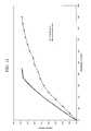
- FIG. 12is a plot illustrating cumulative delivery from a device constructed according to the invention compared to a prior art device.
- FIG. 13is a plot of voltage between cationic and anionic chambers during the test illustrated in FIG. 12 .
- FIG. 14is an exploded view in perspective of another embodiment of the invention.
- Trace line 70is representative of a current profile obtainable in a commercially available and disposable galvanic cell device, such as device 30 .
- Trace line 70shows a reduced current flow over time due to polarization of electrolyte in the areas surrounding the electrodes and a corresponding reduced rate of chemical reaction.
- Trace lines 71 - 73are achievable in minibatteries, with the current, or voltage, fall-off occurring when one, or both, reactant is substantially spent in the chemical reaction.
- Traces 71 - 73illustrate desired current profiles of electromotive cells, such as minibatteries, characterizable as having a substantially “square-wave” over their working life, assuming a sustainable (sufficiently slow) current flow.
- the working lifetime of such a minibatterymay be controlled to have a desired length by providing only a measured amount of one or more reactant chemicals.
- the operational life of a minibatterymay be set to last 20 seconds, 20 minutes, or multiple hours, simply by controlling the quantity of reactive components in the battery.
- a battery with the characteristics indicated by trace line 73may be assembled having about twice as much reactant compared to a battery with the characteristics indicated by trace line 72 .
- a treatment intervalmay, therefore, conveniently be determined by the life of a battery.
- a treatment timemay simply be established by operation by a patient, or by a health care practitioner, of a switch to start and stop a flow of current through the device.
- the total treatment dosemay alternatively also be limited by loading a device with a controlled amount of the ion medicament.
- a minibatteryalso may be constructed to produce a higher voltage than a typical disposable galvanic cell contained in a device 30 .
- a desired voltagemay be created by combining oxidizing and reducing agents having sufficient galvanic activity.
- a battery having the characteristics indicated by trace line 71would have constituent components with lower combined reactivity than a battery having the characteristics indicated by trace lines 72 and 73 .
- Batteriesmay also be arranged in electrical series to boost a voltage supplied by a composite cell, effectively forming a more powerful battery. Such a higher voltage may beneficially establish a flow of ions and cause the ions to migrate at an increased rate to reduce a treatment time requirement.
- a treatment intervalmay also be determined, in part, by the voltage of a battery, or effective battery.
- Minibatteriesmay be manufactured having rugged housings to withstand incidental, or even significant, abuse without incurring sufficient damage to suffer a leak of their contents.
- a battery housingis understood to be rugged if the housing is capable of transferring tissue-damaging loads to a patient while avoiding a content-leaking rupture.
- a minibattery having a paper housing, for example,would be susceptible to developing a leak which could harm a patient.
- a familiar example for a rugged minibattery typeis a button-type battery, which is typically housed in a metal canister resembling a button. Such batteries are commonly employed as power sources for wrist watches. A patient wearing an iontophoretic device incorporating such type of rugged battery would be seriously injured before such a metal button battery would leak due to an object contacting the battery.
- the rugged housingpermits safe use of more reactive materials, such as Lithium, Sodium Hydroxide, and Potassium Hydroxide, with correspondingly higher voltage battery outputs than galvanic reactions using low-concentration electrolyte matched to a human body.
- Minibatteriesare low-cost devices and are available having voltages between about one (1) Volt and about fifteen (15) Volts.
- a minibatterypermits a reduced treatment time in a disposable, single-use, iontophoretic device.
- Rugged minibatteriesmay also be made in a thin and/or flexible form to reduce bulk of a treatment device.
- a desirable minibattery for use in the instant inventionmay be constructed to operate with various metal-anode-based electrochemical reactions.
- Such an anode metalmay include Lithium, Zinc, Magnesium, and Aluminum.
- Certain embodiments of the present inventiondiffer from the prior art by providing an electromotive force, to drive ion migration, in a self-contained disposable package.
- a self-contained packagemay be regarded as providing an electromotive source having a positive pole and a negative pole defined within a single housing. Chemically reactive materials to create a voltage between the positive and negative poles are included inside that housing during manufacture of the electromotive source. The housing is sealed to enclose all of the reactive elements required for electron production. No additional materials, such as electrolyte, must be added subsequent to manufacture of the electromotive source before the source can be used in an electric circuit.
- Such package structuredifferentiates over structure of an electromotive source formed by galvanic coupling between a plurality of chambers, such as is found in commercially available and disposable iontophoretic devices.
- a suitable self-contained package to provide such electromotive forcecan be embodied as a minibattery, including button-cell type minibatteries.
- Such a minibatterymay be the sole electromotive source, or may augment a conventionally distributed galvanic reaction arrangement, of a disposable iontophoretic device.
- a container 84spaces apart a cationic chamber 86 and an anionic chamber 88 .
- the chambersare spaced apart to enable creation, with a cooperating body, of an ion-conducting path of an electric circuit.
- the ion-conducting path portion of the electric circuittransports the treatment ions into the body.
- the container 84may be sized in correspondence with an area of a patient to be treated. For example, local cosmetic treatment of dark areas under a patient's eyes requires a container sized to attach to a small area. General treatment of a human body with drugs, such as lidocaine, may be better accomplished using the larger surface area available on a patient's shoulder, arm, or area of a torso.
- Containers 84may advantageously be formed from a flat and flexible adhesive strip to conform and adhere to a body surface. Containers may also be made in the form of a cartridge, capsule, or tube for insertion into a body volume.
- a first electromotive cell 102is located in the cationic chamber 86 of device 80 .
- a second electromotive cell 104is located in the anionic chamber 88 .
- Cells 102 and 104may be partially or completely inside the respective chambers. It is further within contemplation for a device according to the present invention to have a single minibattery, which may be located in either of chambers 86 or 88 , or simply attached to a container 84 .
- Optional circuit elements 110nonexclusively including an oscillator, a switch, a resistor, a capacitor, and the like, may be present in certain embodiments. If present, such circuit elements 110 typically are located in an electronconducting path 112 (also referred to herein as “conductor 112 ”) between the cationic chamber 86 and the anionic chamber 88 .
- a fluid barrieris created on each electromotive cell in illustrated embodiment 80 to prevent a circuit being formed by electrolyte in a chamber and carrying current between the individual cell's positive and negative poles. Such a current would detrimentally drain the cell and impede operation of a treatment device 80 .
- One way to create a workable fluid barrier on a pair of minibatteriesinvolves placing the batteries in a die. One battery is placed with its negative pole upwards, and the other battery is placed in the die having its positive pole upwards. The spacing between the batteries in the die should be sufficient to permit location of the batteries as desired in a container 84 .
- a conductor 112may be attached between both of the upwardly facing poles, or both of the downwardly facing poles, by spot welding, or using a conductive adhesive.
- a preferably inert fluid-sealing materialsuch as an epoxy, plastic, rubber, urethane, or a silicone-based product, is then applied to portions of the conductor and minibatteries to form the electrolyte barrier.
- the barrier-forming materialmay be painted on, sprayed on, or injected into the die. A portion of one pole of each battery is left uncovered by the electrolyte barrier so that one positive pole and one negative pole are exposed for connection in an electric circuit.
- FIG. 7Additional details of construction of a representative device 80 are illustrated in FIG. 7 .
- Structure of container 84spaces apart cationic chamber 86 and anionic chamber 88 .
- Cationic chamber 86defines a volume 120 in which may be received a minibattery 102 (previously called “electromotive cell”), a portion of conductor 112 , and a substrate 125 .
- a passageway 127formed through a wall of catanionic chamber 86 , provides a path for ion migration toward or away from the catanionic chamber 86 .
- an optional semiporous membrane covering 129may be included to provide a retainer for treatment substances in the catanionic chamber 86 .
- Such a covering 129will be sufficiently permeable to permit ion migration, but desirably will resist fluid flow from the chamber.
- a chamber covering 129may be used to enable preloading of medicament into a stored device, or in the case where a device is inserted into, or placed on, a body.
- anionic chamber 88defines a volume 130 in which may be received a minibattery 104 (previously called “electromotive cell”), a portion of conductor 112 , and a substrate 135 .
- a passageway 137formed through a wall of anionic chamber 88 , provides a path for ion migration toward or away from the chamber 88 .
- an optional semiporous membrane covering 139may be included to provide a retainer for treatment fluids, such as drugs, in the chamber 88 , while permitting ion migration through the passageway 137 .
- a device 80may be attached to a surface of a cooperating body to complete an electric circuit through the body, represented by conductor 142 and resistor R.
- a cooperating bodyis intended to encompass any structure capable of completing an electric circuit by forming a physical contact spanning between the passageways 127 and 137 to form an ion-transporting leg of the circuit.
- Serviceable bodiesinclude human and animal bodies and other structures which may be considered, in a general sense, to act as containers of electrolyte.
- the cationic chamber 86 and anionic chamber 88typically are formed to define relatively wide and shallow volumes. Passageways 127 and 137 desirably are large to provide a correspondingly large contact area over which ions may migrate into a body.
- the chamber volumes 120 , 130are generally shallow to minimize a distance, in a depth direction, ions must travel before entering a body.
- polarization of the electrolyte near conducting terminalscommonly occurs and is the source of current reduction depicted by trace 70 in FIG. 5 .
- One way to decrease the polarization effectis to form substrates 125 and 135 to include conductive elements arranged to better distribute electrons through the chamber volume. In any case, a distributed current transmission is desirable in both types of iontophoretic devices. A desirable distribution may limit an effective sustained current density over a treatment area to less than about 0.5 mA/cm 2 to reduce the chance of a patient experiencing skin irritation during a treatment.
- Substrates 125 and 135may include conductive material affixed to a wall area of one or both chambers. Such conductive material may be painted, sprayed, or otherwise affixed to a portion of, or on the entire inside surface of, a chamber. Desirably, such conductive material will encompass an area opposite, and sized in agreement with, a passageway 127 or 137 .
- a substrate 125 or 135may be formed from a conductive material and distributed through a volume 120 or 130 .
- a workable distributed substratemay be formed by impregnating a conventional substrate, such as a gauze, with a conductive substance, such as a metal powder.
- a substratealso may be made from a metal or metal/polymer composite.
- FIG. 8illustrates an electric schematic of an iontophoretic reaction process.
- Resistances to current flow in such a circuitinclude R b , for resistance through the battery, R g , for resistance through the gauze or from a terminal to an electrolyte, and R s representing skin resistance of a body.
- Polarization of the constituent chemicals in a conventional disposable galvanically driven iontophoretic reactiontends to increase a value for R g , and decrease a transmitted current.
- Distributing a surface for electron transfer through a volume of a chambertends to counter onset of such polarization.
- the benefit to a patient undergoing a treatment with improved electron distributionis an increased and consistent ion delivery rate, permitting a reduced treatment time interval.
- conductors 112 and exposed portions of electromotive cells 102 , 104are desirable for conductors 112 and exposed portions of electromotive cells 102 , 104 to not detrimentally react with treatment chemicals in a chamber 86 or 88 .
- a detrimental reactionwould decrease efficacy of the treatment, or may form a caustic or noxious substance which might irritate a patient's skin.
- One way to resist such undesired chemical interactionis to provide a minibattery or electromotive cell with an inert housing, or coating.
- An exposed electron exchange surface portionmay be made from, or coated with, a chemically inert conductor or noble conductive material.
- a noble conductorcan be defined as a material serviceable to conduct electrons, but otherwise generally nonparticipatory in a chemical reaction with substances in which it is immersed or contacting.
- noble conductive materialsnon-exclusively include molybdenum, gold, silver, carbon, titanium, and tantalum.
- a batterymay be located external to a chamber and electrically connected to a noble conductor located inside a chamber for electron exchange.
- Iontophoretic devicessuch as indicated generally at 150 in FIG. 9 , may be constructed having a different size or shape between cationic and anionic chambers.
- the shape, color, texture or some other discernable characteristic of container 153may also be used as an indicator of the device's use for cationic or anionic treatments.
- a red container 153may signify that the device 150 is for use to dispense anionic-based treatments.
- a yellow container 153may signify that the device 150 is adapted to dispense cationic-based treatments.
- a chamber 155may be preloaded for storage with a hydrogel capable of acting as an electrolyte. A treatment drug then need only be loaded into chamber 157 prior to placing the container 153 onto a body.
- chambers 155 and 157can assist in loading the treatment into the correct chamber to establish treatment ion migration directed toward the body.
- an exposed, or electrolytically connectable, pole of each of batteries 161 and 162will have an appropriate electrical sign, depending on the construction and desired purpose of the device 150 as either a cationic or anionic beneficial agent dispensing device.
- FIG. 10One embodiment of an implantable iontophoretic device according to the instant invention is illustrated generally at 170 in FIG. 10 .
- device 170may be surgically implanted into a body to provide a long-term pain treatment.
- a device 170has an electromotive source 172 housed in a container 174 .
- Illustrated container 174is constructed as a cylinder.
- a barrier 176adapted to prevent an electrolytic circuit between positive and negative poles of electromotive source 172 , is included when the electromotive source 172 includes one or more minibatteries.
- Barrier 176may be adapted sealingly to slide like a piston inside container 174 to accommodate a change in chamber volume due to transfer of ions from a chamber containing a beneficial treatment agent.
- a containercan be constructed directly to expand or contract and thereby accommodate changes in chamber volume.
- Chamber 178can be a cationic chamber when chamber 180 is an anionic chamber.
- Some sort of semipermeable cap 182is provided to cover openings from the respective chambers. Suitable caps 182 permit migration of ions in and out of the chambers, but otherwise resist unintended leaking of chamber contents.
- a device according to the present inventionmay be adapted accurately to dispense a controlled dose of beneficial treatment by incorporating a suitable circuit arrangement in the electron-carrying portion of the device's electric circuit.
- An electric circuitmay be arranged to direct virtually any portion of an electromotive source's available stored energy, from zero to 100 percent, to ion transport.
- a shunt resistor, R pcan be connected in-circuit to form an electron-conducting path parallel to the ion-conducting path through a body.
- a representative switch Scan conveniently be closed by loading a chamber with electrolyte and application of a device to a body to complete the circuit.
- the current flow through the shunt resistor R p and the body resistance R swill be determined by the relative magnitude of the resistance in each path.
- a devicemay, therefore, be constructed to deliver a dose of ion-based treatment corresponding to any portion of a battery's capacity.
- FIGS. 12 and 13illustrate the performance of a device constructed according to the instant invention compared to a comparable device constructed according to the teachings of the Birch Point application.
- the Birch Point devicewas made by forming electrodes from Zn and AgCl.
- the inventionwas embodied with a single 1.5 volt button battery rated at 900 mAmp-min.
- Skin resistance R swas modeled with a 5 k-ohm resistor.
- the shunt resistor R pwas 500 ohms. Useful shunt resistances may range from 1 ohm to about 10,000 ohms, or more.
- the inventiondelivered a current corresponding to an equivalent dose of beneficial agent totaling about 78 mAmp-min in about 400 minutes.
- the Birch Point devicerequired over 850 minutes, or more than twice as long, to accomplish the same dose.
- FIG. 13illustrates the voltage measured between the cationic and anionic chambers during the test illustrated in FIG. 12 .
- the trace of voltage over time for the inventionis not a perfectly “square” square-wave shape. That is, the voltage drops over time, instead of remaining relatively constant for about the first 375 minutes.
- the current discharge through both the shunt and skin pathsexceeds the battery's steady state discharge rate at which battery voltage may remain relatively constant.
- the voltagedoes exhibit a sharp drop as the battery approaches full discharge.
- the batteryinherently expends its energy more rapidly and uniformly than the electrolytic cell, and does so up to substantially complete exhaustion. Such a characteristic is desirable as one way to accurately control a treatment dose.
- the device according to the inventionprovides a disposable iontophoretic apparatus which is faster in delivering a treatment dose and also more precise in termination of the treatment interval.
- FIG. 14One way to manufacture a device to include a shunt resistance in a parallel path between the cationic and anionic chambers is illustrated generally at 190 in FIG. 14 .
- Substrates 192 and electrodes 193 , 194are housed in chambers 196 and 197 .
- Chambers 196 and 197are formed in container 198 , which may beneficially have an adhesive coating on one surface thereof.
- Circuit elements, generally indicated at 200are placed on top of container 198 .
- Circuit elementscan include a battery 202 and a resistor 204 .
- the battery 202 and resistor 204are connected at junction 206 through aperture 208 to electrode 193 .
- Battery 202is connected at junction 209 to electrode 194 through aperture 210 in chamber 196 .
- Resistor 204has terminal 212 disposed through port 213 in chamber 196 , but away from contact with electrode 194 .
- An electrical circuitis formed between junction 209 and terminal 212 only after introduction of an electrolyte to chamber 196 .
- the electrolyteeffectively acts as a switch in-circuit with the battery 202 and resistor 204 .
- a protective top cover 222desirably is placed over the components 200 to provide a pleasing appearance.
Landscapes
- Health & Medical Sciences (AREA)
- Engineering & Computer Science (AREA)
- Bioinformatics & Cheminformatics (AREA)
- General Health & Medical Sciences (AREA)
- Biomedical Technology (AREA)
- Nuclear Medicine, Radiotherapy & Molecular Imaging (AREA)
- Radiology & Medical Imaging (AREA)
- Life Sciences & Earth Sciences (AREA)
- Animal Behavior & Ethology (AREA)
- Public Health (AREA)
- Veterinary Medicine (AREA)
- Pharmacology & Pharmacy (AREA)
- Electrotherapy Devices (AREA)
Abstract
Description
Claims (5)
Priority Applications (4)
| Application Number | Priority Date | Filing Date | Title |
|---|---|---|---|
| US10/067,623US7047069B2 (en) | 2002-02-04 | 2002-02-04 | Iontophoretic fluid delivery device |
| US10/125,014US6775570B2 (en) | 2002-02-04 | 2002-04-18 | Iontophoretic treatment device |
| PCT/US2003/003282WO2003066156A2 (en) | 2002-02-04 | 2003-02-04 | Iontophoretic treatment device |
| AU2003216162AAU2003216162A1 (en) | 2002-02-04 | 2003-02-04 | Iontophoretic treatment device |
Applications Claiming Priority (1)
| Application Number | Priority Date | Filing Date | Title |
|---|---|---|---|
| US10/067,623US7047069B2 (en) | 2002-02-04 | 2002-02-04 | Iontophoretic fluid delivery device |
Related Child Applications (1)
| Application Number | Title | Priority Date | Filing Date |
|---|---|---|---|
| US10/125,014Continuation-In-PartUS6775570B2 (en) | 2002-02-04 | 2002-04-18 | Iontophoretic treatment device |
Publications (2)
| Publication Number | Publication Date |
|---|---|
| US20030149393A1 US20030149393A1 (en) | 2003-08-07 |
| US7047069B2true US7047069B2 (en) | 2006-05-16 |
Family
ID=27658884
Family Applications (1)
| Application Number | Title | Priority Date | Filing Date |
|---|---|---|---|
| US10/067,623Expired - LifetimeUS7047069B2 (en) | 2002-02-04 | 2002-02-04 | Iontophoretic fluid delivery device |
Country Status (1)
| Country | Link |
|---|---|
| US (1) | US7047069B2 (en) |
Cited By (22)
| Publication number | Priority date | Publication date | Assignee | Title |
|---|---|---|---|---|
| US20060253061A1 (en)* | 2005-04-22 | 2006-11-09 | Travanti Pharma Inc. | Transdermal systems for the delivery of therapeutic agents including granisetron using iontophoresis |
| US20070060860A1 (en)* | 2005-08-18 | 2007-03-15 | Transcutaneous Technologies Inc. | Iontophoresis device |
| US20070071807A1 (en)* | 2005-09-28 | 2007-03-29 | Hidero Akiyama | Capsule-type drug-releasing device and capsule-type drug-releasing device system |
| US20070078445A1 (en)* | 2005-09-30 | 2007-04-05 | Curt Malloy | Synchronization apparatus and method for iontophoresis device to deliver active agents to biological interfaces |
| US20070232983A1 (en)* | 2005-09-30 | 2007-10-04 | Smith Gregory A | Handheld apparatus to deliver active agents to biological interfaces |
| US20080102119A1 (en)* | 2006-11-01 | 2008-05-01 | Medtronic, Inc. | Osmotic pump apparatus and associated methods |
| US20080177219A1 (en)* | 2007-01-23 | 2008-07-24 | Joshi Ashok V | Method for Iontophoretic Fluid Delivery |
| US20090005721A1 (en)* | 2005-12-09 | 2009-01-01 | Tti Ellebeau, Inc. | Packaged iontophoresis system |
| US20090187134A1 (en)* | 2005-09-30 | 2009-07-23 | Hidero Akiyama | Iontophoresis Device Controlling Amounts of a Sleep-Inducing Agent and a Stimulant to be Administered and Time at Which the Drugs are Administered |
| US20090216175A1 (en)* | 2005-08-05 | 2009-08-27 | Transcu Ltd. | Transdermal Administration Device and Method of Controlling the Same |
| US20090292328A1 (en)* | 2005-11-30 | 2009-11-26 | Corlius Fourie Birkill | Medical Device |
| US20090299265A1 (en)* | 2005-09-30 | 2009-12-03 | Tti Ellebeau, Inc. | Electrode Assembly for Iontophoresis Having Shape-Memory Separator and Iontophoresis Device Using the Same |
| US20100016781A1 (en)* | 2005-08-29 | 2010-01-21 | Mizuo Nakayama | Iontophoresis device selecting drug to be administered on the basis of information form sensor |
| US20100030128A1 (en)* | 2005-09-06 | 2010-02-04 | Kazuma Mitsuguchi | Iontophoresis device |
| US20100069877A1 (en)* | 2008-09-10 | 2010-03-18 | Smith Gregory A | Apparatus and method to dispense hpc-based viscous liquids into porous substrates, e.g., continuous web-based process |
| US7848801B2 (en) | 2005-12-30 | 2010-12-07 | Tti Ellebeau, Inc. | Iontophoretic systems, devices, and methods of delivery of active agents to biological interface |
| US20100312168A1 (en)* | 2009-06-09 | 2010-12-09 | Yoshimasa Yoshida | Long life high capacity electrode, device, and method of manufacture |
| US7890164B2 (en) | 2005-09-15 | 2011-02-15 | Tti Ellebeau, Inc. | Iontophoresis device |
| US8062783B2 (en) | 2006-12-01 | 2011-11-22 | Tti Ellebeau, Inc. | Systems, devices, and methods for powering and/or controlling devices, for instance transdermal delivery devices |
| US8197844B2 (en) | 2007-06-08 | 2012-06-12 | Activatek, Inc. | Active electrode for transdermal medicament administration |
| US8386030B2 (en) | 2005-08-08 | 2013-02-26 | Tti Ellebeau, Inc. | Iontophoresis device |
| US8862223B2 (en) | 2008-01-18 | 2014-10-14 | Activatek, Inc. | Active transdermal medicament patch and circuit board for same |
Families Citing this family (18)
| Publication number | Priority date | Publication date | Assignee | Title |
|---|---|---|---|---|
| US7476222B2 (en) | 2003-06-30 | 2009-01-13 | Johnson & Johnson Consumer Companies, Inc. | Methods of reducing the appearance of pigmentation with galvanic generated electricity |
| US8734421B2 (en) | 2003-06-30 | 2014-05-27 | Johnson & Johnson Consumer Companies, Inc. | Methods of treating pores on the skin with electricity |
| US7480530B2 (en)* | 2003-06-30 | 2009-01-20 | Johnson & Johnson Consumer Companies, Inc. | Device for treatment of barrier membranes |
| US7477940B2 (en)* | 2003-06-30 | 2009-01-13 | J&J Consumer Companies, Inc. | Methods of administering an active agent to a human barrier membrane with galvanic generated electricity |
| US7477938B2 (en)* | 2003-06-30 | 2009-01-13 | Johnson & Johnson Cosumer Companies, Inc. | Device for delivery of active agents to barrier membranes |
| US20040265395A1 (en)* | 2003-06-30 | 2004-12-30 | Ying Sun | Device for delivery of reducing agents to barrier membranes |
| US7507228B2 (en)* | 2003-06-30 | 2009-03-24 | Johnson & Johnson Consumer Companies, Inc. | Device containing a light emitting diode for treatment of barrier membranes |
| US7486989B2 (en)* | 2003-06-30 | 2009-02-03 | Johnson & Johnson Consumer Companies, Inc. | Device for delivery of oxidizing agents to barrier membranes |
| US7477941B2 (en)* | 2003-06-30 | 2009-01-13 | Johnson & Johnson Consumer Companies, Inc. | Methods of exfoliating the skin with electricity |
| US7479133B2 (en)* | 2003-06-30 | 2009-01-20 | Johnson & Johnson Consumer Companies, Inc. | Methods of treating acne and rosacea with galvanic generated electricity |
| US7477939B2 (en)* | 2003-06-30 | 2009-01-13 | Johnson & Johnson Consumer Companies, Inc. | Methods of treating a wound with galvanic generated electricity |
| US8386029B2 (en) | 2005-03-31 | 2013-02-26 | Encore Medical Asset Corporation | Apparatus for electrotherapy drug delivery with added impurities |
| EP2012706A4 (en)* | 2006-04-20 | 2013-02-13 | Transport Pharmaceuticals Inc | Pharmaceutical formulations for iontophoretic methotrexate delivery |
| WO2008146224A2 (en) | 2007-05-25 | 2008-12-04 | Compex Medical S.A. | Wound healing electrode set |
| US8150525B2 (en)* | 2008-08-27 | 2012-04-03 | Johnson & Johnson Consumer Companies, Inc. | Treatment of hyperhydrosis |
| US20120089232A1 (en) | 2009-03-27 | 2012-04-12 | Jennifer Hagyoung Kang Choi | Medical devices with galvanic particulates |
| ES2617760T3 (en) | 2009-11-13 | 2017-06-19 | Johnson & Johnson Consumer Inc. | Galvanic device for skin treatment |
| CN111551610A (en)* | 2020-04-07 | 2020-08-18 | 上海电气集团股份有限公司 | Vanadium electrolyte concentration testing method, miniature vanadium battery and vanadium electrolyte concentration testing device |
Citations (38)
| Publication number | Priority date | Publication date | Assignee | Title |
|---|---|---|---|---|
| US3604417A (en) | 1970-03-31 | 1971-09-14 | Wayne Henry Linkenheimer | Osmotic fluid reservoir for osmotically activated long-term continuous injector device |
| US3760984A (en) | 1971-09-29 | 1973-09-25 | Alza Corp | Osmotically powered agent dispensing device with filling means |
| US3760805A (en) | 1971-01-13 | 1973-09-25 | Alza Corp | Osmotic dispenser with collapsible supply container |
| US3797494A (en) | 1969-04-01 | 1974-03-19 | Alza Corp | Bandage for the administration of drug by controlled metering through microporous materials |
| US3995631A (en) | 1971-01-13 | 1976-12-07 | Alza Corporation | Osmotic dispenser with means for dispensing active agent responsive to osmotic gradient |
| US4003379A (en) | 1974-04-23 | 1977-01-18 | Ellinwood Jr Everett H | Apparatus and method for implanted self-powered medication dispensing |
| US4034756A (en) | 1971-01-13 | 1977-07-12 | Alza Corporation | Osmotically driven fluid dispenser |
| US4140122A (en) | 1976-06-11 | 1979-02-20 | Siemens Aktiengesellschaft | Implantable dosing device |
| US4141359A (en) | 1976-08-16 | 1979-02-27 | University Of Utah | Epidermal iontophoresis device |
| US4240884A (en) | 1979-02-15 | 1980-12-23 | Oronzio De Nora Implanti Elettrochimici S.P.A. | Electrolytic production of alkali metal hypohalite |
| US4292968A (en)* | 1979-11-26 | 1981-10-06 | Sybron Corporation | Electric supply for ion therapy |
| US4452249A (en) | 1981-12-01 | 1984-06-05 | The Research Foundation Of State University Of New York | Microelectrodes and process for shielding same |
| US4522698A (en) | 1981-11-12 | 1985-06-11 | Maget Henri J R | Electrochemical prime mover |
| US4539004A (en) | 1982-09-22 | 1985-09-03 | Alza Corporation | Self-driven pump assembly and method of operation |
| US4886514A (en) | 1985-05-02 | 1989-12-12 | Ivac Corporation | Electrochemically driven drug dispenser |
| US4929233A (en) | 1988-08-26 | 1990-05-29 | Alza Corporation | Implantable fluid imbibing pump with improved closure |
| US5035711A (en) | 1983-03-24 | 1991-07-30 | Kabushiki Kaisya Advance Kaihatsu Kenkyujo | Transcutaneously implantable element |
| US5041107A (en) | 1989-10-06 | 1991-08-20 | Cardiac Pacemakers, Inc. | Electrically controllable, non-occluding, body implantable drug delivery system |
| US5063175A (en) | 1986-09-30 | 1991-11-05 | North American Philips Corp., Signetics Division | Method for manufacturing a planar electrical interconnection utilizing isotropic deposition of conductive material |
| US5250023A (en) | 1989-10-27 | 1993-10-05 | Korean Research Institute on Chemical Technology | Transdermal administration method of protein or peptide drug and its administration device thereof |
| US5286254A (en) | 1990-06-15 | 1994-02-15 | Cortrak Medical, Inc. | Drug delivery apparatus and method |
| US5413572A (en) | 1990-04-02 | 1995-05-09 | Alza Corporation | Osmotic dosage system for liquid drug delivery |
| US5427870A (en) | 1994-09-06 | 1995-06-27 | Ceramatec, Inc. | Gas releasing electrochemical cell for fluid dispensing applications |
| US5454922A (en) | 1993-05-07 | 1995-10-03 | Ceramatec, Inc. | Fluid dispensing pump |
| US5492534A (en) | 1990-04-02 | 1996-02-20 | Pharmetrix Corporation | Controlled release portable pump |
| US5618265A (en) | 1991-03-11 | 1997-04-08 | Alza Corporation | Iontophoretic delivery device with single lamina electrode |
| US5672167A (en) | 1990-05-21 | 1997-09-30 | Recordati Corporation | Controlled release osmotic pump |
| US5700481A (en) | 1995-03-17 | 1997-12-23 | Takeda Chemical Industries, Ltd. | Transdermal drug delivery process |
| US5735897A (en) | 1993-10-19 | 1998-04-07 | Scimed Life Systems, Inc. | Intravascular stent pump |
| US5869078A (en) | 1996-04-25 | 1999-02-09 | Medtronic Inc. | Implantable variable permeability drug infusion techniques |
| US5876741A (en) | 1995-03-30 | 1999-03-02 | Medlogic Global Corporation | Chemo-mechanical expansion delivery system |
| US5911223A (en) | 1996-08-09 | 1999-06-15 | Massachusetts Institute Of Technology | Introduction of modifying agents into skin by electroporation |
| EP0931564A1 (en) | 1988-10-03 | 1999-07-28 | Alza Corporation | Electrotransport drug delivery |
| US5954268A (en) | 1997-03-03 | 1999-09-21 | Joshi; Ashok V. | Fluid delivery system |
| US5971722A (en) | 1997-09-05 | 1999-10-26 | Baxter International Inc | Electrochemical syringe pump having a sealed storage reservoir for a charge transfer medium |
| US5983130A (en)* | 1995-06-07 | 1999-11-09 | Alza Corporation | Electrotransport agent delivery method and apparatus |
| US6261595B1 (en) | 2000-02-29 | 2001-07-17 | Zars, Inc. | Transdermal drug patch with attached pocket for controlled heating device |
| US6421561B1 (en)* | 1999-12-30 | 2002-07-16 | Birch Point Medical, Inc. | Rate adjustable drug delivery system |
- 2002
- 2002-02-04USUS10/067,623patent/US7047069B2/ennot_activeExpired - Lifetime
Patent Citations (38)
| Publication number | Priority date | Publication date | Assignee | Title |
|---|---|---|---|---|
| US3797494A (en) | 1969-04-01 | 1974-03-19 | Alza Corp | Bandage for the administration of drug by controlled metering through microporous materials |
| US3604417A (en) | 1970-03-31 | 1971-09-14 | Wayne Henry Linkenheimer | Osmotic fluid reservoir for osmotically activated long-term continuous injector device |
| US3760805A (en) | 1971-01-13 | 1973-09-25 | Alza Corp | Osmotic dispenser with collapsible supply container |
| US3995631A (en) | 1971-01-13 | 1976-12-07 | Alza Corporation | Osmotic dispenser with means for dispensing active agent responsive to osmotic gradient |
| US4034756A (en) | 1971-01-13 | 1977-07-12 | Alza Corporation | Osmotically driven fluid dispenser |
| US3760984A (en) | 1971-09-29 | 1973-09-25 | Alza Corp | Osmotically powered agent dispensing device with filling means |
| US4003379A (en) | 1974-04-23 | 1977-01-18 | Ellinwood Jr Everett H | Apparatus and method for implanted self-powered medication dispensing |
| US4140122A (en) | 1976-06-11 | 1979-02-20 | Siemens Aktiengesellschaft | Implantable dosing device |
| US4141359A (en) | 1976-08-16 | 1979-02-27 | University Of Utah | Epidermal iontophoresis device |
| US4240884A (en) | 1979-02-15 | 1980-12-23 | Oronzio De Nora Implanti Elettrochimici S.P.A. | Electrolytic production of alkali metal hypohalite |
| US4292968A (en)* | 1979-11-26 | 1981-10-06 | Sybron Corporation | Electric supply for ion therapy |
| US4522698A (en) | 1981-11-12 | 1985-06-11 | Maget Henri J R | Electrochemical prime mover |
| US4452249A (en) | 1981-12-01 | 1984-06-05 | The Research Foundation Of State University Of New York | Microelectrodes and process for shielding same |
| US4539004A (en) | 1982-09-22 | 1985-09-03 | Alza Corporation | Self-driven pump assembly and method of operation |
| US5035711A (en) | 1983-03-24 | 1991-07-30 | Kabushiki Kaisya Advance Kaihatsu Kenkyujo | Transcutaneously implantable element |
| US4886514A (en) | 1985-05-02 | 1989-12-12 | Ivac Corporation | Electrochemically driven drug dispenser |
| US5063175A (en) | 1986-09-30 | 1991-11-05 | North American Philips Corp., Signetics Division | Method for manufacturing a planar electrical interconnection utilizing isotropic deposition of conductive material |
| US4929233A (en) | 1988-08-26 | 1990-05-29 | Alza Corporation | Implantable fluid imbibing pump with improved closure |
| EP0931564A1 (en) | 1988-10-03 | 1999-07-28 | Alza Corporation | Electrotransport drug delivery |
| US5041107A (en) | 1989-10-06 | 1991-08-20 | Cardiac Pacemakers, Inc. | Electrically controllable, non-occluding, body implantable drug delivery system |
| US5250023A (en) | 1989-10-27 | 1993-10-05 | Korean Research Institute on Chemical Technology | Transdermal administration method of protein or peptide drug and its administration device thereof |
| US5413572A (en) | 1990-04-02 | 1995-05-09 | Alza Corporation | Osmotic dosage system for liquid drug delivery |
| US5492534A (en) | 1990-04-02 | 1996-02-20 | Pharmetrix Corporation | Controlled release portable pump |
| US5672167A (en) | 1990-05-21 | 1997-09-30 | Recordati Corporation | Controlled release osmotic pump |
| US5286254A (en) | 1990-06-15 | 1994-02-15 | Cortrak Medical, Inc. | Drug delivery apparatus and method |
| US5618265A (en) | 1991-03-11 | 1997-04-08 | Alza Corporation | Iontophoretic delivery device with single lamina electrode |
| US5454922A (en) | 1993-05-07 | 1995-10-03 | Ceramatec, Inc. | Fluid dispensing pump |
| US5735897A (en) | 1993-10-19 | 1998-04-07 | Scimed Life Systems, Inc. | Intravascular stent pump |
| US5427870A (en) | 1994-09-06 | 1995-06-27 | Ceramatec, Inc. | Gas releasing electrochemical cell for fluid dispensing applications |
| US5700481A (en) | 1995-03-17 | 1997-12-23 | Takeda Chemical Industries, Ltd. | Transdermal drug delivery process |
| US5876741A (en) | 1995-03-30 | 1999-03-02 | Medlogic Global Corporation | Chemo-mechanical expansion delivery system |
| US5983130A (en)* | 1995-06-07 | 1999-11-09 | Alza Corporation | Electrotransport agent delivery method and apparatus |
| US5869078A (en) | 1996-04-25 | 1999-02-09 | Medtronic Inc. | Implantable variable permeability drug infusion techniques |
| US5911223A (en) | 1996-08-09 | 1999-06-15 | Massachusetts Institute Of Technology | Introduction of modifying agents into skin by electroporation |
| US5954268A (en) | 1997-03-03 | 1999-09-21 | Joshi; Ashok V. | Fluid delivery system |
| US5971722A (en) | 1997-09-05 | 1999-10-26 | Baxter International Inc | Electrochemical syringe pump having a sealed storage reservoir for a charge transfer medium |
| US6421561B1 (en)* | 1999-12-30 | 2002-07-16 | Birch Point Medical, Inc. | Rate adjustable drug delivery system |
| US6261595B1 (en) | 2000-02-29 | 2001-07-17 | Zars, Inc. | Transdermal drug patch with attached pocket for controlled heating device |
Non-Patent Citations (2)
| Title |
|---|
| PCT International Search Report, PCT/US09/03282, dated Jul. 31, 2003, 5 pages. |
| Scott et al. electrochemically reactive cathodes for electrotransport device, US Patent Pub No. US 2002/0055704. |
Cited By (27)
| Publication number | Priority date | Publication date | Assignee | Title |
|---|---|---|---|---|
| US9764130B2 (en) | 2005-04-22 | 2017-09-19 | Teva Pharmaceuticals International Gmbh | Transdermal systems for the delivery of therapeutic agents including granisetron using iontophoresis |
| US8463373B2 (en)* | 2005-04-22 | 2013-06-11 | Teikoku Pharma Usa, Inc. | Transdermal systems for the delivery of therapeutic agents including granisetron using iontophoresis |
| US20110087154A1 (en)* | 2005-04-22 | 2011-04-14 | Travanti Pharma Inc. | Transdermal Systems for the Delivery of Therapeutic Agents Including Granisetron Using Iontophoresis |
| US20060253061A1 (en)* | 2005-04-22 | 2006-11-09 | Travanti Pharma Inc. | Transdermal systems for the delivery of therapeutic agents including granisetron using iontophoresis |
| US7856263B2 (en)* | 2005-04-22 | 2010-12-21 | Travanti Pharma Inc. | Transdermal systems for the delivery of therapeutic agents including granisetron using iontophoresis |
| US20090216175A1 (en)* | 2005-08-05 | 2009-08-27 | Transcu Ltd. | Transdermal Administration Device and Method of Controlling the Same |
| US8386030B2 (en) | 2005-08-08 | 2013-02-26 | Tti Ellebeau, Inc. | Iontophoresis device |
| US20070060860A1 (en)* | 2005-08-18 | 2007-03-15 | Transcutaneous Technologies Inc. | Iontophoresis device |
| US20100016781A1 (en)* | 2005-08-29 | 2010-01-21 | Mizuo Nakayama | Iontophoresis device selecting drug to be administered on the basis of information form sensor |
| US20100030128A1 (en)* | 2005-09-06 | 2010-02-04 | Kazuma Mitsuguchi | Iontophoresis device |
| US7890164B2 (en) | 2005-09-15 | 2011-02-15 | Tti Ellebeau, Inc. | Iontophoresis device |
| US20070071807A1 (en)* | 2005-09-28 | 2007-03-29 | Hidero Akiyama | Capsule-type drug-releasing device and capsule-type drug-releasing device system |
| US20070232983A1 (en)* | 2005-09-30 | 2007-10-04 | Smith Gregory A | Handheld apparatus to deliver active agents to biological interfaces |
| US20090187134A1 (en)* | 2005-09-30 | 2009-07-23 | Hidero Akiyama | Iontophoresis Device Controlling Amounts of a Sleep-Inducing Agent and a Stimulant to be Administered and Time at Which the Drugs are Administered |
| US20090299265A1 (en)* | 2005-09-30 | 2009-12-03 | Tti Ellebeau, Inc. | Electrode Assembly for Iontophoresis Having Shape-Memory Separator and Iontophoresis Device Using the Same |
| US20070078445A1 (en)* | 2005-09-30 | 2007-04-05 | Curt Malloy | Synchronization apparatus and method for iontophoresis device to deliver active agents to biological interfaces |
| US20090292328A1 (en)* | 2005-11-30 | 2009-11-26 | Corlius Fourie Birkill | Medical Device |
| US20090005721A1 (en)* | 2005-12-09 | 2009-01-01 | Tti Ellebeau, Inc. | Packaged iontophoresis system |
| US7848801B2 (en) | 2005-12-30 | 2010-12-07 | Tti Ellebeau, Inc. | Iontophoretic systems, devices, and methods of delivery of active agents to biological interface |
| US20080102119A1 (en)* | 2006-11-01 | 2008-05-01 | Medtronic, Inc. | Osmotic pump apparatus and associated methods |
| US20110184389A1 (en)* | 2006-11-01 | 2011-07-28 | Medtronic, Inc. | Osmotic pump apparatus and associated methods |
| US8062783B2 (en) | 2006-12-01 | 2011-11-22 | Tti Ellebeau, Inc. | Systems, devices, and methods for powering and/or controlling devices, for instance transdermal delivery devices |
| US20080177219A1 (en)* | 2007-01-23 | 2008-07-24 | Joshi Ashok V | Method for Iontophoretic Fluid Delivery |
| US8197844B2 (en) | 2007-06-08 | 2012-06-12 | Activatek, Inc. | Active electrode for transdermal medicament administration |
| US8862223B2 (en) | 2008-01-18 | 2014-10-14 | Activatek, Inc. | Active transdermal medicament patch and circuit board for same |
| US20100069877A1 (en)* | 2008-09-10 | 2010-03-18 | Smith Gregory A | Apparatus and method to dispense hpc-based viscous liquids into porous substrates, e.g., continuous web-based process |
| US20100312168A1 (en)* | 2009-06-09 | 2010-12-09 | Yoshimasa Yoshida | Long life high capacity electrode, device, and method of manufacture |
Also Published As
| Publication number | Publication date |
|---|---|
| US20030149393A1 (en) | 2003-08-07 |
Similar Documents
| Publication | Publication Date | Title |
|---|---|---|
| US7047069B2 (en) | Iontophoretic fluid delivery device | |
| US6775570B2 (en) | Iontophoretic treatment device | |
| US7031768B2 (en) | Controlled dosage drug delivery | |
| EP1599255B1 (en) | Iontophoretic drug delivery system | |
| US20100106075A1 (en) | Method for iontophoretic fluid delivery | |
| US6421561B1 (en) | Rate adjustable drug delivery system | |
| US6584349B1 (en) | Low cost electrodes for an iontophoretic device | |
| JP4262410B2 (en) | Electrical transmission electrode assembly with low initial resistance | |
| US5084008A (en) | Iontophoresis electrode | |
| US5057072A (en) | Iontophoresis electrode | |
| KR940000071B1 (en) | Skin Permeable Drug Applicator | |
| AU658246B2 (en) | Control device for electrotransport drug delivery | |
| EP1608433B1 (en) | Electrotransport device having a reservoir housing having a flexible conductive element | |
| EP0240593B1 (en) | Improved transdermal drug applicator and electrodes therefor | |
| US5320731A (en) | Iontophoresis device for transcutaneous administration of a given total quantity of an active principle to a subject | |
| KR0168443B1 (en) | Electro therapeutic device | |
| HUP0402663A2 (en) | Electrotransport device having an integrally molded reservoir housing | |
| JP2905980B2 (en) | Iontophoresis electrode | |
| JP2009523712A (en) | Dry matrix as a drug reservoir in electrotransport applications | |
| HK1087049B (en) | Electrotransport device having a reservoir housing having a flexible conductive element |
Legal Events
| Date | Code | Title | Description |
|---|---|---|---|
| AS | Assignment | Owner name:CERAMATEC, INC., UTAH Free format text:ASSIGNMENT OF ASSIGNORS INTEREST;ASSIGNOR:JOSHI, DR. ASHOK V.;REEL/FRAME:015354/0705 Effective date:20041110 | |
| STCF | Information on status: patent grant | Free format text:PATENTED CASE | |
| AS | Assignment | Owner name:MICROLIN, L.L.C, UTAH Free format text:ASSIGNMENT OF ASSIGNORS INTEREST;ASSIGNOR:CERAMATEC, INC.;REEL/FRAME:020794/0583 Effective date:20080331 | |
| FEPP | Fee payment procedure | Free format text:PAT HOLDER CLAIMS SMALL ENTITY STATUS, ENTITY STATUS SET TO SMALL (ORIGINAL EVENT CODE: LTOS); ENTITY STATUS OF PATENT OWNER: SMALL ENTITY | |
| FPAY | Fee payment | Year of fee payment:4 | |
| AS | Assignment | Owner name:ACTIVATEK, INC., UTAH Free format text:ASSIGNMENT OF ASSIGNORS INTEREST;ASSIGNOR:MICROLIN, LLC;REEL/FRAME:026810/0210 Effective date:20110803 | |
| FPAY | Fee payment | Year of fee payment:8 | |
| MAFP | Maintenance fee payment | Free format text:PAYMENT OF MAINTENANCE FEE, 12TH YR, SMALL ENTITY (ORIGINAL EVENT CODE: M2553) Year of fee payment:12 |