US7047057B2 - Simultaneous multiwavelength TPSF-based optical imaging - Google Patents
Simultaneous multiwavelength TPSF-based optical imagingDownload PDFInfo
- Publication number
- US7047057B2 US7047057B2US10/050,941US5094102AUS7047057B2US 7047057 B2US7047057 B2US 7047057B2US 5094102 AUS5094102 AUS 5094102AUS 7047057 B2US7047057 B2US 7047057B2
- Authority
- US
- United States
- Prior art keywords
- wavelengths
- light
- imaging
- injection
- positions
- Prior art date
- Legal status (The legal status is an assumption and is not a legal conclusion. Google has not performed a legal analysis and makes no representation as to the accuracy of the status listed.)
- Expired - Lifetime, expires
Links
- 238000012634optical imagingMethods0.000titleclaimsdescription10
- BEBDNAPSDUYCHM-UHFFFAOYSA-N8-[4-(4-fluorophenyl)-4-oxobutyl]sulfanyl-1,3-dimethyl-6-sulfanylidene-7h-purin-2-oneChemical compoundN1C=2C(=S)N(C)C(=O)N(C)C=2N=C1SCCCC(=O)C1=CC=C(F)C=C1BEBDNAPSDUYCHM-UHFFFAOYSA-N0.000titleabstract3
- 238000003384imaging methodMethods0.000claimsabstractdescription30
- 238000001514detection methodMethods0.000claimsabstractdescription25
- 230000000295complement effectEffects0.000claimsabstractdescription4
- 238000002347injectionMethods0.000claimsdescription32
- 239000007924injectionSubstances0.000claimsdescription32
- 239000000835fiberSubstances0.000claimsdescription26
- 238000000034methodMethods0.000claimsdescription21
- 230000003287optical effectEffects0.000claimsdescription9
- 230000002123temporal effectEffects0.000claimsdescription6
- 239000013307optical fiberSubstances0.000claimsdescription4
- 238000002059diagnostic imagingMethods0.000claimsdescription3
- 238000009792diffusion processMethods0.000claimsdescription3
- 210000000481breastAnatomy0.000description7
- 238000000576coating methodMethods0.000description3
- 230000008878couplingEffects0.000description3
- 238000010168coupling processMethods0.000description3
- 238000005859coupling reactionMethods0.000description3
- 230000010363phase shiftEffects0.000description3
- 239000011248coating agentSubstances0.000description2
- 230000003595spectral effectEffects0.000description2
- 238000010521absorption reactionMethods0.000description1
- 238000010009beatingMethods0.000description1
- 230000005540biological transmissionEffects0.000description1
- 210000004556brainAnatomy0.000description1
- 238000010586diagramMethods0.000description1
- 238000005516engineering processMethods0.000description1
- 238000001914filtrationMethods0.000description1
- 230000002035prolonged effectEffects0.000description1
- 238000000926separation methodMethods0.000description1
- 230000011664signalingEffects0.000description1
- 230000000087stabilizing effectEffects0.000description1
Images

Classifications
- A—HUMAN NECESSITIES
- A61—MEDICAL OR VETERINARY SCIENCE; HYGIENE
- A61B—DIAGNOSIS; SURGERY; IDENTIFICATION
- A61B5/00—Measuring for diagnostic purposes; Identification of persons
- A61B5/0059—Measuring for diagnostic purposes; Identification of persons using light, e.g. diagnosis by transillumination, diascopy, fluorescence
- A61B5/0082—Measuring for diagnostic purposes; Identification of persons using light, e.g. diagnosis by transillumination, diascopy, fluorescence adapted for particular medical purposes
- A61B5/0091—Measuring for diagnostic purposes; Identification of persons using light, e.g. diagnosis by transillumination, diascopy, fluorescence adapted for particular medical purposes for mammography
- A—HUMAN NECESSITIES
- A61—MEDICAL OR VETERINARY SCIENCE; HYGIENE
- A61B—DIAGNOSIS; SURGERY; IDENTIFICATION
- A61B5/00—Measuring for diagnostic purposes; Identification of persons
- A61B5/43—Detecting, measuring or recording for evaluating the reproductive systems
- A61B5/4306—Detecting, measuring or recording for evaluating the reproductive systems for evaluating the female reproductive systems, e.g. gynaecological evaluations
- A61B5/4312—Breast evaluation or disorder diagnosis
- G—PHYSICS
- G01—MEASURING; TESTING
- G01N—INVESTIGATING OR ANALYSING MATERIALS BY DETERMINING THEIR CHEMICAL OR PHYSICAL PROPERTIES
- G01N21/00—Investigating or analysing materials by the use of optical means, i.e. using sub-millimetre waves, infrared, visible or ultraviolet light
- G01N21/17—Systems in which incident light is modified in accordance with the properties of the material investigated
- G01N21/47—Scattering, i.e. diffuse reflection
- G01N21/49—Scattering, i.e. diffuse reflection within a body or fluid
Definitions
- the present inventionrelates to the field of temporal point spread function (TPSF) based imaging in which objects which diffuse light, such as human body tissue, are imaged using signals resulting from the injection of light into the object and detection of the diffusion of the light in the object at a number of positions while gathering TPSF-based data to obtain information beyond simple attenuation such as scattering and absorption. More particularly, the present invention relates to a method and apparatus for simultaneous multi-wavelength TPSF-based imaging which reduces image acquisition time, and also promises to provide enhanced image information.
- TPSFtemporal point spread function
- Time-domain optical medical imagesshow great promise as a technique for imaging breast tissue, as well as the brain and other body parts.
- the objectiveis to analyze at least a part of the temporal point spread function (TPSF) of an injected light pulse as it is diffused in the tissue, and the information extracted from the TPSF is used in constructing a medically useful image.
- TPSFtemporal point spread function
- time domaina high intensity, short duration pulse is injected and the diffused light is detected within a much longer time frame than the pulse, but nonetheless requiring high-speed detection equipment.
- frequency domainlight is modulated in amplitude at a range of frequencies from the kHz range to about 0.5 GHz.
- the light injectedis modulated but essentially continuous, and the information collected is the amplitude and the phase difference of the light at the detector.
- the acquisition of the datarequires the two parameters of amplitude and phase shift to be recorded for a large number of modulation frequencies within the dynamic range provided.
- the TPSFcould be calculated by inverse Fourier transform, however, the image is typically generated using the frequency domain data.
- the breastIn optical imaging of human breast tissue, the breast is immobilized by stabilizing plates of the optical head. Although the light injected is not harmful, prolonged imaging time is uncomfortable for patients, particularly in the case of female breast imaging in which the breast is typically secured between support members or plates, and is typically immersed in a bath or surrounded by a coupling medium contained in a bag. While optical imaging promises a safer and potentially a more medically useful technique, imaging time and related patient discomfort remains a problem in providing a competitively superior technique.
- this objectis achieved by using a plurality of distinguishable wavelengths simultaneously to acquire simultaneously a plurality of TPSF-based imaging data points.
- different injection-detection positionsmay be used simultaneously to collect imaging data points simultaneously for the different injection-detection positions, thus covering more imaging area faster.
- the wavelengthsmay provide complementary information about the object being imaged.
- a method of TPSF-based optical imagingcomprising the steps of injecting light at a plurality of wavelengths into an object to be imaged at one or more injection positions, and detecting the injected light after diffusing in the object at one or more detection positions simultaneously for the plurality of wavelengths to obtain separate TPSF-based data for each of the wavelengths.
- the inventionalso provides a TPSF-based optical imaging apparatus comprising at least one source providing light at a plurality of wavelengths, a plurality of injection ports and lightguides coupled to the at least one source for injecting the light into an object to be imaged at one or more injection positions, a plurality of detection ports and lightguides, a wavelength selection device coupled to the plurality of detection ports and lightguides for separating the plurality of wavelengths, and a camera detecting the plurality of wavelengths separated by the device.
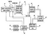
- FIG. 1illustrates schematically the components of the imaging system according to the preferred embodiment including the laser sources, injection and detection port apparatus, multiwavelength detector, detector signal processor and imaging computer station;
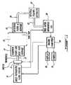
- FIG. 2illustrates an optical schematic diagram of the imaging system according to the preferred embodiment showing the multiple waveguide paths between the detection ports and the detector, as well as the multiplexed multiple wavelength source arrangement;
- FIG. 3illustrates a side view of the detection fibers coupled to a detector using a collimating fiber holder
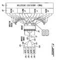
- FIG. 4illustrates a plan view of the detector faceplate surface having four quadrants each provided with a different wavelength selective filter coating.
- the inventionis applied to the case of time domain optical medical imaging, however, it will be apparent to those skilled in the art that the invention is applicable to frequency domain techniques for optical imaging.
- the injected pulses at each of the plurality of wavelengthsare preferably simultaneously injected, however, for the imaging to be “simultaneous”, the time window reserved for acquiring the TPSF from a single wavelength's injection pulse using the chosen detector overlaps between the respective wavelengths even if the injected pulses were not simultaneous. In the preferred embodiment, it is important to respect the temporal resolution of the detector as better described hereinbelow.
- the pulsed light source 10has an output (in practice, it will comprise a plurality of laser source outputs at discrete wavelengths, as described further hereinbelow) optically coupled via a switch 11 to one of plurality of waveguides 12 to a number of injection ports of a support 14 .
- the injection portsare preferably positioned at a number of fixed positions over the imaging area for each wavelength to be used, although the injection port may alternatively be movable over the body surface, provided that the body part 16 is immobilized.
- the injection and detection portsmay directly contact the body or a coupling medium may be used between the body and the injection/detection ports.
- the detection ports and support 18are arranged in FIG. 1 in transmission mode for breast imaging. It also possible to arrange detection ports on the same surface of the patient as the injection ports, in which case imaging is achieved by measuring the TPSF of the diffused pulse reflected from the tissue.
- the light injectedis preferably pulses having a duration of about 1 to 100 picoseconds and an average power of about 100 mW.
- the laser source 10preferably comprises four laser sources operating at 760 nm, 780 nm, 830 nm, and 850 nm. These different wavelengths allow for complementary information to be acquired to build a physiological image of the breast tissue. As better shown in FIG. 2 , the output of each wavelength laser source 10 a to 10 d , for the four wavelengths chosen, are coupled to fibers 12 a to 12 d respectively.
- the fibersare preferably multimode fibers, such as 200/240 micron graded index multimode fibers.
- FIG. 2illustrates for simplicity four injection positions and four detection positions, it will be understood that there may be about 10 injection positions and typically up to about 50 detector positions.
- the light from the four sourcesis preferably injected at the same point, and the light is coupled onto a same fiber 12 f , as shown in FIG. 2 , using a coupler 12 e , or alternatively the four fibers 12 a to 12 d could be fed as a bundle to the same position within support 14 .
- multiplexing the four wavelengths onto the same fiber 12 fallows a conventional single wavelength support 14 to be used without taking into account different injection positions within the program of the imaging computer or processor 30 .
- FIG. 2illustrates a single fiber (or bundle) 12 f
- a fiber switch 11such as a conventional 1 by 32 JDS Uniphase switch is used to switch light from each laser source 10 to a desired one of the injection port positions.
- the detected optical signalsare communicated by waveguides 20 , namely 400/440 micron graded index multimode optical fibers, to a spectral channel separator 22 , namely a series of filters in the preferred embodiment.
- the filtersmay comprise band-pass filter coatings 22 a , 22 b , 22 c , and 22 d on a faceplate 24 of the detector 26 .
- Each detection fiber 20is coupled directly to the detector 26 without switching, in the preferred embodiment. While it is possible for the separator 22 to switch and/or demultiplex the light from fibers 20 onto lightguides 23 , as illustrated in FIG. 1 , in the preferred embodiment shown in FIGS.
- the fibers 20are mounted in a collimating fiber holder or positioner 21 for directing the light from each fiber 20 to the filter 22 and then onto the detector surface 26 .
- the collimating holderhas a collimating microlens for coupling the light exiting the core of the fiber 20 onto the detector surface with a small spot size.
- an array of 50 fibersis arranged in each quadrant or zone of the faceplate 24 at the detector 26 .
- spectral separationmay also be achieved using an optical spectrometer or a grating device, such as an arrayed waveguide grating or the like, instead of using a filtering medium or coating.
- the injection and detection locationsare the same for each wavelength, however, individual positions for lightguides for each wavelengths can be accommodated, e.g. the detector ports could support 200 positions fiber.
- the wavelength separated signalsare all detected simultaneously by a gated intensified CCD camera, for example a PicoStar Camera by LaVision.
- the camera 26is used to detect the light from each detection port 18 and at each desired wavelength with picosecond resolution.
- the injected pulsemay spread out over several picoseconds to several nanoseconds as a result of diffusion through the body tissue.
- a large number of pulsesare injected and their corresponding camera signals are processed by imaging computer 30 to determine one data point, i.e. the temporal point spread function for a particular wavelength and a particular injection port and detection port combination.
- the TPSFis measured at a number of detector positions at which the detected signal provides good signal to noise.
- Such data pointsare gathered for a large number of combinations of wavelengths and port positions to obtain sufficient “raw” data to begin constructing an image of the tissue.
- the resulting imagecan be displayed on display 32 and printed on a printer 34 .
- the imaging computer 30is also responsible for signaling a laser source 10 to select a desired wavelength and then switch that wavelength signal to a desired output fiber 12 .
- the computer 30thus progresses through all desired wavelength and position combinations to achieve the desired imaging.
- the laser source 10synchronizes the camera 26 with each pulse.
- the laser source 10may also comprise a number of fixed wavelength optical sources, as it may also comprise a single broadband source.
- the laser 10will be controlled to be modulated at the desired frequency and switch its output onto the desired fiber 12 .
- the computer 30will then need to sweep through a large number of modulation frequencies at which the amplitude and phase shift of the detected light is recorded with good accuracy.
- the TPSF for a single data pointcan be calculated from the amplitude and phase shift data set recorded, or typically, the frequency domain data is used directly to reconstruct the image.
- a plurality of wavelengthsthat can be separately detected. While these distinct wavelengths can be generated from a monochromatic or broadband light source to directly provide the desired wavelengths, it is alternatively possible to mix a first basic wavelength with a second reference wavelength to create a beating of the wavelengths. This can be used to tune the basic wavelength to create the desired wavelength at the plurality of wavelengths and is another way of providing the light to be injected according to the invention. Given that the light source has two parts for the first and second wavelengths, it is possible to control or pulse only one to achieve the desired light injection.
Landscapes
- Health & Medical Sciences (AREA)
- Life Sciences & Earth Sciences (AREA)
- Pathology (AREA)
- General Health & Medical Sciences (AREA)
- Physics & Mathematics (AREA)
- Surgery (AREA)
- Public Health (AREA)
- Engineering & Computer Science (AREA)
- Biomedical Technology (AREA)
- Heart & Thoracic Surgery (AREA)
- Medical Informatics (AREA)
- Molecular Biology (AREA)
- Veterinary Medicine (AREA)
- Animal Behavior & Ethology (AREA)
- Biophysics (AREA)
- Gynecology & Obstetrics (AREA)
- Reproductive Health (AREA)
- Chemical & Material Sciences (AREA)
- Analytical Chemistry (AREA)
- Biochemistry (AREA)
- General Physics & Mathematics (AREA)
- Immunology (AREA)
- Investigating Or Analysing Materials By Optical Means (AREA)
- Measurement Of The Respiration, Hearing Ability, Form, And Blood Characteristics Of Living Organisms (AREA)
Abstract
Description
Claims (15)
Priority Applications (6)
| Application Number | Priority Date | Filing Date | Title |
|---|---|---|---|
| US10/050,941US7047057B2 (en) | 2001-07-16 | 2002-01-22 | Simultaneous multiwavelength TPSF-based optical imaging |
| CA2453644ACA2453644C (en) | 2001-07-16 | 2002-07-16 | Simultaneous multiwavelength tpsf-based optical imaging |
| EP02757990AEP1409995A1 (en) | 2001-07-16 | 2002-07-16 | Simultaneous multiwavelength tpsf-based optical imaging |
| JP2003514240AJP2004536304A (en) | 2001-07-16 | 2002-07-16 | TPSF optical imaging by simultaneous multi-wavelength method |
| PCT/CA2002/001082WO2003008945A1 (en) | 2001-07-16 | 2002-07-16 | Simultaneous multiwavelength tpsf-based optical imaging |
| CNA02816086XACN1543568A (en) | 2001-07-16 | 2002-07-16 | Simultaneous multiwavelength TPSF-based optical imaging |
Applications Claiming Priority (2)
| Application Number | Priority Date | Filing Date | Title |
|---|---|---|---|
| US30508001P | 2001-07-16 | 2001-07-16 | |
| US10/050,941US7047057B2 (en) | 2001-07-16 | 2002-01-22 | Simultaneous multiwavelength TPSF-based optical imaging |
Publications (2)
| Publication Number | Publication Date |
|---|---|
| US20030085338A1 US20030085338A1 (en) | 2003-05-08 |
| US7047057B2true US7047057B2 (en) | 2006-05-16 |
Family
ID=26728877
Family Applications (1)
| Application Number | Title | Priority Date | Filing Date |
|---|---|---|---|
| US10/050,941Expired - LifetimeUS7047057B2 (en) | 2001-07-16 | 2002-01-22 | Simultaneous multiwavelength TPSF-based optical imaging |
Country Status (6)
| Country | Link |
|---|---|
| US (1) | US7047057B2 (en) |
| EP (1) | EP1409995A1 (en) |
| JP (1) | JP2004536304A (en) |
| CN (1) | CN1543568A (en) |
| CA (1) | CA2453644C (en) |
| WO (1) | WO2003008945A1 (en) |
Cited By (4)
| Publication number | Priority date | Publication date | Assignee | Title |
|---|---|---|---|---|
| US20040181153A1 (en)* | 2003-03-12 | 2004-09-16 | Hall David Jonathan | Method and apparatus for combining continuous wave and time domain optical imaging |
| US20060247531A1 (en)* | 2005-04-27 | 2006-11-02 | The Trustees Of Dartmouth College | System and method for spectral-encoded high-rate hemodynamic tomography |
| US20080218727A1 (en)* | 2006-12-22 | 2008-09-11 | Art, Advanced Research Technologies Inc. | Method and apparatus for optical image reconstruction using contour determination |
| US20090103096A1 (en)* | 2004-12-30 | 2009-04-23 | Art, Advanced Research Technologies Inc. | Method for determining optical properties of turbid media |
Families Citing this family (11)
| Publication number | Priority date | Publication date | Assignee | Title |
|---|---|---|---|---|
| AU2003282929A1 (en)* | 2002-10-17 | 2004-05-04 | Iridex Corporation | Laser delivery device incorporating a plurality of laser source optical fibers |
| JP4499495B2 (en)* | 2004-07-01 | 2010-07-07 | 財団法人光科学技術研究振興財団 | Pulse light transmission apparatus and pulse light transmission adjustment method |
| WO2006116672A2 (en)* | 2005-04-27 | 2006-11-02 | The Trustees Of Dartmouth College | Systems and methods for tomographic image reconstruction |
| WO2008015604A2 (en) | 2006-07-31 | 2008-02-07 | Koninklijke Philips Electronics N.V. | Measurement with multiplexed detection |
| WO2008096289A1 (en) | 2007-02-05 | 2008-08-14 | Koninklijke Philips Electronics N.V. | Device and method for acquiring image data from a turbid medium |
| EP2057941A1 (en)* | 2007-11-07 | 2009-05-13 | Koninklijke Philips Electronics N.V. | Method and device for imaging an interior of an optically turbid medium |
| WO2013049264A1 (en)* | 2011-09-28 | 2013-04-04 | Carestream Health, Inc. | Frame-sequential multiwavelength imaging system and method |
| CN104076001A (en)* | 2013-12-17 | 2014-10-01 | 浙江工商大学 | Detection device based on laser array and large yellow croaker storage time detection method |
| CN105223137B (en)* | 2015-10-20 | 2017-10-24 | 希肯医疗技术(苏州)有限公司 | A kind of optical measuring device for detection of biological samples |
| US20240129054A1 (en)* | 2022-10-12 | 2024-04-18 | Ciena Corporation | Method and apparatus for performing spread spectrum optical spectroscopy |
| WO2024081713A1 (en)* | 2022-10-12 | 2024-04-18 | Ciena Corporation | Method and apparatus for performing spread spectrum optical spectroscopy |
Citations (5)
| Publication number | Priority date | Publication date | Assignee | Title |
|---|---|---|---|---|
| US5694938A (en)* | 1995-06-07 | 1997-12-09 | The Regents Of The University Of California | Methodology and apparatus for diffuse photon mimaging |
| US5987351A (en)* | 1995-01-03 | 1999-11-16 | Non-Invasive Technology, Inc. | Optical coupler for in vivo examination of biological tissue |
| US20010027316A1 (en)* | 2000-01-21 | 2001-10-04 | Gregory Kenton W. | Myocardial revascularization-optical reflectance catheter and method |
| US6339216B1 (en)* | 1997-11-26 | 2002-01-15 | Imaging Diagnostic Systems, Inc. | Time-resolved breast imaging device |
| US6509729B2 (en)* | 2001-01-09 | 2003-01-21 | The United States Of America As Represented By The Secretary Of The Navy | Multiple simultaneous optical frequency measurement |
Family Cites Families (2)
| Publication number | Priority date | Publication date | Assignee | Title |
|---|---|---|---|---|
| US4515165A (en)* | 1980-02-04 | 1985-05-07 | Energy Conversion Devices, Inc. | Apparatus and method for detecting tumors |
| US5772597A (en)* | 1992-09-14 | 1998-06-30 | Sextant Medical Corporation | Surgical tool end effector |
- 2002
- 2002-01-22USUS10/050,941patent/US7047057B2/ennot_activeExpired - Lifetime
- 2002-07-16CACA2453644Apatent/CA2453644C/ennot_activeExpired - Lifetime
- 2002-07-16EPEP02757990Apatent/EP1409995A1/ennot_activeWithdrawn
- 2002-07-16WOPCT/CA2002/001082patent/WO2003008945A1/enactiveApplication Filing
- 2002-07-16CNCNA02816086XApatent/CN1543568A/enactivePending
- 2002-07-16JPJP2003514240Apatent/JP2004536304A/enactivePending
Patent Citations (5)
| Publication number | Priority date | Publication date | Assignee | Title |
|---|---|---|---|---|
| US5987351A (en)* | 1995-01-03 | 1999-11-16 | Non-Invasive Technology, Inc. | Optical coupler for in vivo examination of biological tissue |
| US5694938A (en)* | 1995-06-07 | 1997-12-09 | The Regents Of The University Of California | Methodology and apparatus for diffuse photon mimaging |
| US6339216B1 (en)* | 1997-11-26 | 2002-01-15 | Imaging Diagnostic Systems, Inc. | Time-resolved breast imaging device |
| US20010027316A1 (en)* | 2000-01-21 | 2001-10-04 | Gregory Kenton W. | Myocardial revascularization-optical reflectance catheter and method |
| US6509729B2 (en)* | 2001-01-09 | 2003-01-21 | The United States Of America As Represented By The Secretary Of The Navy | Multiple simultaneous optical frequency measurement |
Cited By (9)
| Publication number | Priority date | Publication date | Assignee | Title |
|---|---|---|---|---|
| US20040181153A1 (en)* | 2003-03-12 | 2004-09-16 | Hall David Jonathan | Method and apparatus for combining continuous wave and time domain optical imaging |
| US7720525B2 (en)* | 2003-03-12 | 2010-05-18 | New Art Advanced Research Technologies Inc. | Method and apparatus for combining continuous wave and time domain optical imaging |
| US20090103096A1 (en)* | 2004-12-30 | 2009-04-23 | Art, Advanced Research Technologies Inc. | Method for determining optical properties of turbid media |
| US7859671B2 (en)* | 2004-12-30 | 2010-12-28 | Art, Advanced Research Technologies Inc. | Method for determining optical properties of turbid media |
| US20060247531A1 (en)* | 2005-04-27 | 2006-11-02 | The Trustees Of Dartmouth College | System and method for spectral-encoded high-rate hemodynamic tomography |
| US20090247847A1 (en)* | 2005-04-27 | 2009-10-01 | The Trustees Of Dartmouth College | Systems and methods for tomographic image reconstruction |
| US7962198B2 (en)* | 2005-04-27 | 2011-06-14 | The Trustees Of Dartmouth College | System and method for spectral-encoded high-rate hemodynamic tomography |
| US8000775B2 (en)* | 2005-04-27 | 2011-08-16 | The Trustees Of Dartmouth College | Systems and methods for tomographic image reconstruction |
| US20080218727A1 (en)* | 2006-12-22 | 2008-09-11 | Art, Advanced Research Technologies Inc. | Method and apparatus for optical image reconstruction using contour determination |
Also Published As
| Publication number | Publication date |
|---|---|
| US20030085338A1 (en) | 2003-05-08 |
| CA2453644C (en) | 2012-09-11 |
| WO2003008945A1 (en) | 2003-01-30 |
| CN1543568A (en) | 2004-11-03 |
| JP2004536304A (en) | 2004-12-02 |
| EP1409995A1 (en) | 2004-04-21 |
| CA2453644A1 (en) | 2003-01-30 |
Similar Documents
| Publication | Publication Date | Title |
|---|---|---|
| US7047057B2 (en) | Simultaneous multiwavelength TPSF-based optical imaging | |
| DE69738291T2 (en) | METHOD AND DEVICE FOR CARRYING OUT OPTICAL MEASUREMENTS BY MEANS OF AN ENDOSCOPE, CATHETER OR GUIDE WIRE WITH A FIBER OPTIC PICTURE SYSTEM | |
| EP1051106B1 (en) | Method and device for tissue modulation | |
| US8634082B2 (en) | Pulsed lasers in frequency domain diffuse optical tomography and spectroscopy | |
| DE10043162B4 (en) | Tube for joining hollow shaft with cam or hub, has shaft end surface aligned with front surface of hub and front surface of head including seal to obtain pressure-resistant sealing connection under application of retention force | |
| US7414729B2 (en) | System and method for coherent anti-Stokes Raman scattering endoscopy | |
| US5309907A (en) | Measuring arrangement for examining a subject with visible, NIR or IR light | |
| KR100352689B1 (en) | Advanced synchronous luminescence system | |
| US9545223B2 (en) | Functional near infrared spectroscopy imaging system and method | |
| EP1828711B1 (en) | A system for generating three- or two-dimensional images | |
| DE10038875B4 (en) | endoscope system | |
| DE60317085T2 (en) | SPECTROSCOPIC CATHETER SYSTEM WITH WIDE TUNING SOURCE | |
| US20050018201A1 (en) | Apparatus and method for ranging and noise reduction of low coherence interferometry lci and optical coherence tomography oct signals by parallel detection of spectral bands | |
| DE3856381T2 (en) | CATHETER SYSTEM FOR IMAGE | |
| JPH09505407A (en) | Optical tissue inspection device | |
| WO2004046696A1 (en) | Composite spectral measurement method and its spectral detection instrument | |
| AU2003210669A2 (en) | Apparatus and method for rangings and noise reduction of low coherence interferometry LCI and optical coherence tomography (OCT) signals by parallel detection of spectral bands | |
| EP0728440A2 (en) | Method and device for deep, selective, non-invasive detection of muscle activity | |
| EP3812722A1 (en) | Spectrometer including tunable on-chip laser and spectrum measurement method | |
| DE60320024T2 (en) | Spectroscopic catheter system with power stable tunable light source | |
| WO1995033987A1 (en) | Method and device for imaging an object using light | |
| KR102746930B1 (en) | High-speed multi-mode optical imaging device using beam splitter and blood flow velocity and blood oxygen saturation measurement method using the optical imaging device | |
| JP2004147706A (en) | Apparatus and method for determining non-invasive biomedical component | |
| Lange et al. | A hyperspectral time resolved DOT system to monitor physiological changes of the human brain activity | |
| JP2004184402A (en) | Biological light measurement device |
Legal Events
| Date | Code | Title | Description |
|---|---|---|---|
| AS | Assignment | Owner name:ART, ADVANCED RESEARCH TECHNOLOGIES INC., CANADA Free format text:ASSIGNMENT OF ASSIGNORS INTEREST;ASSIGNORS:HALL, DAVID;BOUDREAULT, RICHARD;BEAUDRY, PIERRE A.;REEL/FRAME:012779/0639;SIGNING DATES FROM 20020108 TO 20020115 | |
| STCF | Information on status: patent grant | Free format text:PATENTED CASE | |
| AS | Assignment | Owner name:NEW ART ADVANCED RESEARCH TECHNOLOGIES INC.,CANADA Free format text:ASSIGNMENT OF ASSIGNORS INTEREST;ASSIGNOR:ART ADVANCED RESEARCH TECHNOLOGIES INC.;REEL/FRAME:018597/0320 Effective date:20061127 Owner name:NEW ART ADVANCED RESEARCH TECHNOLOGIES INC., CANAD Free format text:ASSIGNMENT OF ASSIGNORS INTEREST;ASSIGNOR:ART ADVANCED RESEARCH TECHNOLOGIES INC.;REEL/FRAME:018597/0320 Effective date:20061127 | |
| REMI | Maintenance fee reminder mailed | ||
| FPAY | Fee payment | Year of fee payment:4 | |
| SULP | Surcharge for late payment | ||
| AS | Assignment | Owner name:ART ADVANCED RESEARCH TECHNOLOGIES INC., QUEBEC Free format text:CHANGE OF NAME;ASSIGNOR:NEW ART ADVANCED RESEARCH TECHNOLOGIES INC.;REEL/FRAME:026479/0052 Effective date:20061127 Owner name:DORSKY WORLDWIDE CORP., VIRGIN ISLANDS, BRITISH Free format text:ASSIGNMENT OF ASSIGNORS INTEREST;ASSIGNOR:ART ADVANCED RESEARCH TECHNOLOGIES INC.;REEL/FRAME:026466/0001 Effective date:20091211 | |
| AS | Assignment | Owner name:SOFTSCAN HEALTHCARE GROUP LTD., VIRGIN ISLANDS, BR Free format text:CHANGE OF NAME;ASSIGNOR:DORSKY WORLDWIDE CORP.;REEL/FRAME:026469/0916 Effective date:20110608 | |
| FEPP | Fee payment procedure | Free format text:PAT HOLDER CLAIMS SMALL ENTITY STATUS, ENTITY STATUS SET TO SMALL (ORIGINAL EVENT CODE: LTOS); ENTITY STATUS OF PATENT OWNER: SMALL ENTITY | |
| FPAY | Fee payment | Year of fee payment:8 | |
| FEPP | Fee payment procedure | Free format text:MAINTENANCE FEE REMINDER MAILED (ORIGINAL EVENT CODE: REM.) | |
| FEPP | Fee payment procedure | Free format text:11.5 YR SURCHARGE- LATE PMT W/IN 6 MO, SMALL ENTITY (ORIGINAL EVENT CODE: M2556) | |
| MAFP | Maintenance fee payment | Free format text:PAYMENT OF MAINTENANCE FEE, 12TH YR, SMALL ENTITY (ORIGINAL EVENT CODE: M2553) Year of fee payment:12 |