US7046765B2 - Radiosurgery x-ray system with collision avoidance subsystem - Google Patents
Radiosurgery x-ray system with collision avoidance subsystemDownload PDFInfo
- Publication number
- US7046765B2 US7046765B2US10/814,451US81445104AUS7046765B2US 7046765 B2US7046765 B2US 7046765B2US 81445104 AUS81445104 AUS 81445104AUS 7046765 B2US7046765 B2US 7046765B2
- Authority
- US
- United States
- Prior art keywords
- collision avoidance
- arm assembly
- exclusion zones
- emission head
- head
- Prior art date
- Legal status (The legal status is an assumption and is not a legal conclusion. Google has not performed a legal analysis and makes no representation as to the accuracy of the status listed.)
- Expired - Lifetime
Links
Images


Classifications
- G—PHYSICS
- G05—CONTROLLING; REGULATING
- G05B—CONTROL OR REGULATING SYSTEMS IN GENERAL; FUNCTIONAL ELEMENTS OF SUCH SYSTEMS; MONITORING OR TESTING ARRANGEMENTS FOR SUCH SYSTEMS OR ELEMENTS
- G05B19/00—Programme-control systems
- G05B19/02—Programme-control systems electric
- G05B19/18—Numerical control [NC], i.e. automatically operating machines, in particular machine tools, e.g. in a manufacturing environment, so as to execute positioning, movement or co-ordinated operations by means of programme data in numerical form
- G05B19/406—Numerical control [NC], i.e. automatically operating machines, in particular machine tools, e.g. in a manufacturing environment, so as to execute positioning, movement or co-ordinated operations by means of programme data in numerical form characterised by monitoring or safety
- G05B19/4061—Avoiding collision or forbidden zones
- A—HUMAN NECESSITIES
- A61—MEDICAL OR VETERINARY SCIENCE; HYGIENE
- A61N—ELECTROTHERAPY; MAGNETOTHERAPY; RADIATION THERAPY; ULTRASOUND THERAPY
- A61N5/00—Radiation therapy
- A61N5/10—X-ray therapy; Gamma-ray therapy; Particle-irradiation therapy
- A—HUMAN NECESSITIES
- A61—MEDICAL OR VETERINARY SCIENCE; HYGIENE
- A61N—ELECTROTHERAPY; MAGNETOTHERAPY; RADIATION THERAPY; ULTRASOUND THERAPY
- A61N5/00—Radiation therapy
- A61N5/10—X-ray therapy; Gamma-ray therapy; Particle-irradiation therapy
- A61N5/1077—Beam delivery systems
- A61N5/1081—Rotating beam systems with a specific mechanical construction, e.g. gantries
- A—HUMAN NECESSITIES
- A61—MEDICAL OR VETERINARY SCIENCE; HYGIENE
- A61B—DIAGNOSIS; SURGERY; IDENTIFICATION
- A61B6/00—Apparatus or devices for radiation diagnosis; Apparatus or devices for radiation diagnosis combined with radiation therapy equipment
- A61B6/44—Constructional features of apparatus for radiation diagnosis
- A61B6/4429—Constructional features of apparatus for radiation diagnosis related to the mounting of source units and detector units
- A61B6/4464—Constructional features of apparatus for radiation diagnosis related to the mounting of source units and detector units the source unit or the detector unit being mounted to ceiling
- G—PHYSICS
- G05—CONTROLLING; REGULATING
- G05B—CONTROL OR REGULATING SYSTEMS IN GENERAL; FUNCTIONAL ELEMENTS OF SUCH SYSTEMS; MONITORING OR TESTING ARRANGEMENTS FOR SUCH SYSTEMS OR ELEMENTS
- G05B2219/00—Program-control systems
- G05B2219/30—Nc systems
- G05B2219/49—Nc machine tool, till multiple
- G05B2219/49137—Store working envelop, limit, allowed zone
Definitions
- the present inventionrelates to radiosurgery and radiotherapy.
- Radiosurgeryvery intense and precisely focused doses of radiation in a beam from a source outside a patient's body are delivered to a target region in the body, in order to destroy tumorous cells.
- the target regionconsists of a volume of tumorous tissue.
- Radiosurgeryrequires an extremely accurate spatial localization of the targeted tumors. Radiosurgery offers obvious advantages over conventional surgery, during which a surgeon's scalpel removes the tumor, by avoiding the common risks and problems associated with open surgery. These problems include invasiveness, high costs, the need for in-hospital stays and general anesthesia, and complications associated with post-operative recovery. When a cancerous tumor is located close to critical organs, nerves, or arteries, the risks of open surgery are even greater.
- CT and MRI scansenable practitioners to precisely locate a tumor relative to skeletal landmarks or implanted fiducial markers.
- Stereotactic frameshave been developed and used in the past for treatment of brain tumors.
- Stereotactic framesare rigid metal frames that are attached to the patient's skull and locked in place to provide a frame of reference for the surgeon during CT/MRI imaging, and for subsequent therapeutic treatment.
- a stereotactic frameis typically attached to the patient prior to scanning/imaging. The frame must remain in place while the surgeon is developing a computerized treatment plan, as well as during the actual treatment.
- an x-ray or gamma ray sourceis precisely positioned with respect to the frame, so that the radiation can be administered according to the treatment plan.
- frame-based radiosurgeryhas a number of drawbacks. These drawbacks mostly relate to the use of the stereotactic frame.
- a stereotactic framecauses pain to the patient, since it has to be attached with screws.
- a framecannot be easily re-attached in precisely the same position for a subsequent radiation procedure, so that frame-based radiosurgical treatment is limited to smaller tumors (generally less than about three centimeters in diameter) that can be treated in a single procedure.
- frame-based radiosurgerycannot be used for tumors located outside of the head and neck region, because of the above-described difficulty of attaching these frames to anatomical regions other than the skull. Frame-based radiosurgery therefore cannot be used to treat ninety percent of all solid tumors, because they occur outside of the head/neck region.
- CyberKnifeis an image guided robotic system which eliminates the need for the rigid stereotactic frames described above, and enables the treatment of extra-cranial tumor sites.
- CyberKnifeprovides numerous advantages compared to conventional stereotactic radiosurgery systems, including but not limited to: ability to treat tumors throughout the body, not just those located within the head/neck region; increased access to, and coverage of, any target volume; ability to treat tumors that are larger than about three centimeters in diameter; minimal constraints on patient set-up; ability to deliver a plurality of fractionated treatments; and enhanced ability to avoid damaging critical structures.
- CyberKnifeincludes a robotic system onto which an x-ray linear accelerator (“linac”) is mounted, and a controller.
- the linacis adapted to selectively provide a precisely shaped and timed radiation beam.
- the controlleruses CT and possibly MRI data, or other types of image data, that define the target tissue and important other bodily structures, together with treatment planning and delivery software to identify a series of landmarks within the treatment region, prior to surgery.
- CyberKnifemay further include a stereo x-ray imaging system, which during treatment repeatedly measures the location and orientation of these landmarks relative to the linac.
- the controllerPrior to the delivery of radiation at each delivery site, the controller directs the robotic system to adjust the position and orientation of the linac in accordance with the measurements made by the x-ray imaging system, so that a desired series of radiation beams can be applied to the body, optimally dosing the target tissue while minimizing radiation to other body structures.
- CyberKnifeallows accurate delivery of high doses of radiation, without requiring a stereotactic frame.
- the robotic systemdoes not collide with objects (for example, parts of the patient's body, its own structure, or other equipment in the treatment room). Since patient setup is minimally constrained by a frameless radiosurgery system, it is difficult to have complete knowledge of the patient's body position when preparing a treatment plan, particularly regarding their arms and legs. An obstacle detection/collision avoidance system would therefore be desirable in frameless radiosurgery systems such as the CyberKnife.
- radiotherapyrefers to a procedure in which radiation is applied to a target region for therapeutic, rather than necrotic, purposes.
- the amount of radiation utilized in radiotherapyis typically about an order of magnitude smaller, as compared to the amount used in radiosurgery.
- Radiotherapyis frequently used to treat early stage, curable cancers.
- radiotherapy systemsIn addition to delivering radiation to cancerous tissue, radiotherapy systems generally also irradiate a certain amount of normal tissue surrounding the tumor. Typically, a series of relatively small doses are delivered over a number of days. Each radiation dose not only kills a little of the tumor, but also creates some collateral damage to healthy surrounding tissue, which however usually heals by itself, because it has a greater ability to repair, compared to cancerous tissue.
- a collision avoidance systemwould also be desirable when CyberKnife is being used for radiotherapy, as well as for radiosurgery.
- radiosurgeryin this application shall henceforth mean “radiosurgery and/or radiotherapy.”
- the present inventionprovides a frameless radiosurgery system having a collision avoidance subsystem.
- a frameless radiosurgery system in accordance with the present inventionincludes an x-ray source, and a robot.
- the robotincludes an arm assembly extending from a base unit.
- the x-ray sourcewhich in a preferred form is a linac, has an emission head mounted at a distal end of the arm assembly.
- the x-ray emission headis adapted for selectively emitting an x-ray beam along a beam axis.
- the arm assemblymay be articulated (i.e., have a series of rigid elements linked by rotatable couplings), may be flexible (i.e., have a series of rigid or flexible elements linked by flexible couplings), or may be a combination of both articulated and flexible portions.
- the radiosurgery systemfurther includes an associated controller for selectively orienting the x-ray emission head whereby the x-ray beam extends along a succession of treatment axes.
- the radiosurgery systemfurther includes a collision avoidance subsystem, including means for preventing the x-ray emission head and the arm assembly from effecting a collision with an object in one or more pre-defined exclusion zones.
- the collision avoidance subsystemincludes a light source (such as a laser or an LED (light-emitting-diode)) effective to establish a substantially planar (or sheet-like) light beam between the exclusion zone and the emission head.
- the planar light beammay be fan-shaped.
- the controlleris responsive to observation of an object extending through the light beam, to interrupt any further motion of the head toward the exclusion zone.
- the light sourcemay be fixedly positioned with respect to the x-ray emission head, defining an exclusive zone that “travels” with the head.
- the light sourcemay be fixedly positioned with respect to the base unit of the robot, for example by being mounted on a wall of the treatment room, defining an exclusive zone that is fixed with respect to the treatment room.
- the collision avoidance subsystemincludes a least one optical emitter-receiver pair that is effective to detect the breaking of a light beam when an object extends into the one or more exclusion zones.
- the optical emitteris a light source, as described in paragraph 15 above.
- the optical receiveris constructed and arranged to receive light that 1) has reached an object that has intruded into one or more of the exclusion zones, and 2) is back-scattered from the object.
- the collision avoidance subsystemincludes a laser rangefinder that can detect movement of an object into a light beam.
- the laser rangefinderincludes a transmitter that generate laser light and transmits the light toward one or more exclusion zones, and a receiver/photodetector for receiving and detecting laser light that is backscattered from any object that intrudes into the one or more exclusion zones.
- the laser rangefinderincludes means for determining, from the received back-scattered laser light, the distance to the object.
- a plurality of exclusion zonesmay be defined.
- multiple “layers” of exclusion zonesmay be defined.
- a first “shell-like” exclusion zonemay be defined which slows down the motion of the head.
- a second exclusion zonemay be defined, which completely stops any further motion of the head, when the head reaches one or more boundaries between the first exclusion zone and the second exclusion zone.
- at least one of the exclusion zonesis not a static zone, but rather is a variable dimension exclusion zone.
- the collision avoidance subsystemincludes an array of acoustic transducers fixedly coupled to the x-ray emission head. Each of the transducers transmits a succession of acoustic pulses along a transmission axis extending from the head, and detects acoustic energy backscattered along the transmission axis from an object disposed along the transmission axis.
- the beam axesare mutually aligned whereby cross-sections of adjacent pairs of the pulses transverse to the transmission axis are contiguous at a predetermined distance from the head.
- the collision avoidance subsystemincludes means for determining, from the received backscattered acoustic energy, the distance between the head and the object.
- the collision avoidance subsystemfurther includes means for interrupting, in response to the determined distance being at or less than a predetermined value, any further motion of the head toward the exclusion zone.
- the collision avoidance subsystemincludes a sensor disposed on a surface of the articulated arm assembly.
- the sensoris operative to generate an alarm signal upon impact of the sensor with an object, during motion of the arm assembly and/or the x-ray emission head.
- the subsystemfurther includes means responsive to the alarm signal to interrupt any further motion of the arm and/or head.
- the sensormay be a tactile sensor, or other type of sensor adapted for proximity sensing.
- the sensormay consist of a fluid-filled bladder, and a pressure transducer coupled to the bladder, in one embodiment of the invention.
- the sensormay be an infrared (IR) sensor, or an electrostatic capacitance sensor.
- the detection of breach of the exclusion zone and the system's response to such detectionmay be automatic (e.g., under control of the controller) or may be manually implemented (e.g., when a human observer detects a breach, that observer initiates the system response (e.g., halting further advance of the head).
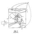
- FIG. 1illustrates a frameless stereotactic radiosurgery system known in the prior art.
- FIG. 2illustrates a frameless stereotactic radiosurgery x-ray system including a collision avoidance subsystem, constructed in accordance with an exemplary embodiment of the present invention.
- FIG. 3Aillustrates a collision avoidance subsystem, in which a light source is fixedly positioned with respect to the base unit of a robot that manipulates the position of the x-ray linac.
- FIG. 3Billustrates a collision avoidance subsystem, in which a light source is fixedly positioned with respect to the x-ray emission head of an x-ray linac.
- FIG. 4illustrates a collision avoidance subsystem, constructed in accordance with another embodiment of the present invention, and including an array of acoustic transducers.
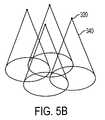
- FIG. 5Aillustrates an array of four ultrasonic transducers, arranged about an x-ray emission head in a rectangular pattern.
- FIGS. 5B and 5Cillustrate sense cones formed by the ultrasonic transducers shown in FIG. 5A .
- FIG. 6illustrates a collision avoidance subsystem, constructed in accordance with another embodiment of the present invention, and including a tactile sensor.
- the present inventionprovides a frameless radiosurgery system including an x-ray source and an associated robot positioning system and a collision avoidance subsystem.
- the collision avoidance subsystemprevents the x-ray source, the robot system, or components of the robot system, from colliding with any critical components (for example the patient, or parts of the radiosurgery system, or other equipment).
- FIG. 1illustrates a frameless stereotactic radiosurgery (and/or radiotherapy) system 10 known in the art.
- An exemplary radiosurgery (and/or radiotherapy) x-ray systemis described in commonly-owned U.S. Pat. No. 5,207,223 and in commonly-owned U.S. Pat. No. 5,427,097.
- the radiosurgery system 10includes: a robot system 12 , having a fixed base and including an articulated arm assembly; a radiation source 14 mounted at the distal end of the articulated arm assembly; a stereo x-ray imaging system 16 ; and a controller 18 .
- the radiation source 14is preferably an x-ray linear accelerator (“linac”).
- the stereo x-ray imaging system 16typically consists of a pair of x-ray sources 17 , and a pair of x-ray image detectors 21 , each detector being opposite an associated one of x-ray sources 17 .
- the controller 18contains treatment planning and delivery software 20 , which is responsive to CT and/or MRI data and user input to generate a treatment plan consisting of a succession of desired beam paths, each having an associated dose rate and a duration at each of a fixed set of nodes.
- the robot 12moves (and orients) the x-ray source and controls beam intensity, successively and sequentially through each of the nodes, while delivering the associated dose.
- FIG. 2illustrates a frameless stereotactic radiosurgery x-ray system 100 that is similar to system 10 but further includes a collision avoidance subsystem 200 , constructed in accordance with an exemplary embodiment of the present invention.
- the radiosurgery x-ray system 100 in the illustrated embodimentincludes a robot system 102 ; a radiation source 104 ; an x-ray imaging system 106 ; a controller 108 ; and a collision avoidance subsystem 200 .
- a patient positioning table 122may support the patient relative to the x-ray imaging system 106 and other equipment. Once in position, the position table 122 remains fixed throughout the treatment.
- the robot systemis an industrial robot/manipulator 102 .
- a Fanuc 420 or Kuka 210may be used.
- the robot system 102includes an articulated arm assembly 112 extending to a distal end 113 from a base unit 114 , affixed to the floor of the treatment room.
- the radiation source 104is mounted at the distal end 113 of the arm 112 .
- the radiation sourceis a small x-ray linac (linear accelerator) 104 .
- the linac 104includes a waveguide, through which microwave radiation is fed in, so as to accelerate electrons.
- the electronsmay be produced by a pulsed electron gun, by way of example.
- the linac 104includes an x-ray emission head 105 adapted for selectively emitting an x-ray beam 120 along a beam axis 121 .
- the linac 104also includes a collimator 107 for collimating the x-ray beam 120 , before the beam 120 is delivered to the desired treatment region.
- the linac 104typically weighs about 100 kg, although other weight ranges are also within the scope of the present invention.
- the x-ray imaging system 106may include two x-ray sources 124 mounted to the ceiling of the treatment room, and a pair of x-ray image detectors 126 mounted orthogonally, typically on the floor. Each of the detectors 126 is opposite an associated one of x-ray sources 124 .
- the x-ray image detectors 126may be amorphous silicon image detectors or cameras.
- the controller 108includes the software operating system for the frameless radiosurgery system 100 .
- the controller 108may be a dual processor computer, which performs numerous functions, including but not limited to: 1) performing treatment planning: 2) providing 3-D displays of images (e.g., from x-ray data); 3) calculating the requisite dose at each desired node; 4) controlling the x-ray linac and the robotic arm; 5) managing and recording the treatment; and 6) monitoring the equipment for patient safety.
- a CT scanis taken of the tumor region, i.e. of the portion of the patient's anatomy that contains the tumors of interest.
- a set of digitally reconstructed radiographs (DRRs)are generated for the tumor region, based on the pre-operative CT scan.
- DRRsare artificial, synthesized 2D images that represent the shadowgraphic image of the tumor that would be obtained, if imaging beams were used having the same intensity, position, and angle as the beams used to generate real time radiographic images of the tumor, and if the tumor were positioned in accordance with the 3D CT scan.
- the image detectors 126then obtain live (“real-time”) radiographic images, by capturing x-ray images from the ceiling-mounted x-ray sources 124 .
- the controller 108correlates these live radiographic images with the pre-computed array of synthetic radiographs, and directs the robot 102 to adjust the position of the linac 104 accordingly.
- patient location and movementis tracked by the matching the “live” x-ray images to the pre-computed set of synthetic images that correspond to various projected movements of the patient.
- Standard image processing techniquesare used to subtract the images and obtain a measure of the differences between the images.
- the resulting imaging informationis transferred to the robot 102 by the controller 108 , which directs the robot 102 to compensate for any changes in patient position by repositioning the linac 104 .
- the articulated arm assembly 112manipulates the linac 104 in order to accommodate tumor movement, caused by patient movement.
- the controller 108selectively orients the emission head 105 of the linac 104 , whereby the emitted x-ray beam extends along a succession of treatment axes, in order to destroy tumors located within the pre-scanned treatment region.
- the treatment axesare disposed in a patient zone surrounding the patient.
- the articulated arm assembly 112 of the robot 102moves around in order to adjust the position of the linac 104 , in response to directions from the controller 108 , it is important to prevent any part of the robotic system 102 , and the linac 104 , from colliding with other objects in the treatment room.
- These objectsmay include, but are not limited to, other parts of the patient's body, and other equipment such as the patient positioning system.
- the present inventionfeatures a collision avoidance subsystem 200 for detecting, and responding to, the relative passage of the x-ray source or any part of the robot system 102 into a predefined exclusion zone 140 .
- the exclusion zone 140is fixed relative to, and surrounds (at least in part) the patient.
- a predefined exclusion zone 140is fixed with respect to, and travels with, the emission head (the x-ray source).
- collision detection subsystem 200detects, and responds to, relative passage of any object (e.g., the patient or equipment or any other object) into the exclusion zone.
- the collision avoidance system 200prevents collision of any part of robot system and/or x-ray source with any object in the exclusion zone 140 .
- the collision avoidance system 200detects intrusion of an object into the exclusion zone 140 and upon such detection, prevents or slows down further relative advance of such object in the exclusion zone.
- the collision avoidance system 200is effective to prevent the radiosurgical (or radiotherapeutic) x-ray head itself from entering the exclusion zone(s), instead of preventing the collision between an object and any part of the robot system and/or x-ray source within the exclusion zone.
- a computer-aided design (CAD) model of the room used for radiosurgery treatmentis set up by the operating system in the controller 108 , prior to treatment.
- the exclusion zone 140is computed by the treatment planning software in the controller 108 .
- the exclusion zone 140defines a region surrounding the patient within which neither the x-ray linac 104 nor the articulated arm assembly 112 of the robot system 102 may enter.
- a number of parametersmay be used in the computation of the exclusion zone 140 , including but not limited to: the size and dimensions of the patient; the expected movements of the patient during treatment; and the location of the patient positioning system 122 .
- This exclusion zonecan be updated in real time by feedback from, for instance, the patient positioning system 122 .
- more than one exclusion zonemay be computed and defined.
- a plurality (or multiple “layers”) of exclusion zonesmay be defined.
- a first “shell-like” exclusion zonemay be defined in which the motion of the head is slowed down, but not completely halted.
- a second exclusion zonemay be defined, which completely stops any further motion of the head, when the head reaches the boundary between the first exclusion zone and the second exclusion zone.
- the collision avoidance subsystem 200uses one or more light sources to define the exclusion zone 140 .
- the one or more light sourcesare effective to establish a set of substantially planar (or sheet) light beams between the pre-computed exclusion zone 140 and the x-ray emission head 105 of the linac 104 , by sweeping one or more linear light beams into substantially planar pattern light beams.
- one or more light sourcesare fixedly positioned with respect to the base unit 114 of the robotic system 102 .
- the light sourcesmay be mounted to a wall of the treatment room. The light sources establish a substantially planar light beam by sweeping a linear light beam along a plane.
- a “rectangular” exclusion zone 140is illustrated in FIG. 3A .
- the exclusion zone 140is defined by three distinct planar light beams, 150 A, 150 B, and 150 C.
- Each planar light beamextends from a respective one of line sources 160 A, 160 B, and 160 C, mounted to the wall, where each “line source” is a plurality of light sources (lasers or LEDs) that are lined up to form a “line” of light sources.
- the principal plane of beam 150 Ais perpendicular to the principal plane of beam 150 B, which is perpendicular to the principal plane of beam 150 C, establishing an inverted U-shaped channel extending about the exclusion zone 140 and parallel to a patient axis 170 of the exclusion zone 140 .
- the dimensions of the beams 150 A, 150 B, and 150 Care such that a patient lying along axis 170 on a table beneath the zone 140 is wholly within the zone 140 .
- the beams 150 A, 150 B, and 150 Cmay be formed by a linear array of light sources (such as lasers or LEDs) extending along each of 160 A, 160 B, and 160 C.
- each of the planar beams 150 A, 150 B, and 150 Cmay be formed from a single light source (such as a laser or an LED) for each beam, which is repetitively swept in the principal planes of these beams.
- the collision avoidance systemincludes at least one optical emitter-receiver pair that is capable of detecting the breaking of a light beam as the light beam reaches an object within an exclusion zone, and is scattered off that object.
- at least one of the light sources(described in paragraphs 44–46 above) is provided with a corresponding light receiver (not illustrated).
- the light receiverreceives light from a light beam that was generated by the light source (i.e. the “emitter” in the emitter-receiver pair), then was “broken” by reason of being incident upon an object extending through one of the exclusion zones, and of being back-scattered by that object.
- a photodetectormay be coupled to the light receiver, to detected the intensity of the back-scattered light.
- the collision avoidance subsystemincludes a laser rangefinder (or equivalently a lidar, an acronym that stands for LIght Detection And Ranging) that can detect movement of an object into a light beam defining the exclusion zone.
- a laser rangefinderis a laser device that can accurately measure the distance to an object by sending out light to the object and analyzing the light that is reflected/scattered off of the object. The range to the object is determined by measuring the time for the light to reach the object and return.
- the laser rangefindermay include: 1) a transmitter that generates laser light and transmits the laser light toward one or more exclusion zones, or toward one or more boundaries of the exclusion zone; 2) a receiver for receiving the transmitted light that is back-scattered from any object that intrudes into the one or more exclusion zones; 3) a photodetector for detecting the intensity of the light received by the receiver; and 4) a data acquisition system, effective to compute the distance to the object by making time-of-flight measurements, i.e. by measuring the time required for the light to reach the object and return.
- the transmitterincludes a laser source for generating laser light.
- a laser sourcefor generating laser light.
- a diode-pumped Nd—YAG (neodymium-yttrium-aluminum-garnet) lasermay be used; however, any other commercially available laser source may be used.
- the transmittermay also include a light-beam steering unit for directed the generated laser light towards the desired exclusion zone or boundary thereof.
- the receivermay be any conventional light receiver that is commercially available.
- the photodetectormay be a photomultiplier tube or avalanche photodiode.
- the data acquisition systemmay include a time-of-flight electronics unit (including one or more amplifiers, a clock oscillator, one or more filters, a digitizer, and a demodulator) and a microprocessor controller.
- the transmitter component of the laser rangefindermay be coupled to the x-ray emission head.
- the transmittergenerates and transmits a laser pulse along a light axis extending from the head, and detects laser light back-scattered along the light axis from an object disposed along the light axis.
- the receiver, detector, and data acquisition components of the laser rangefinderdetermines, from the received backscattered laser light, the distance between the head and the object.
- the microprocessor controller unitmay include means for interrupting, in response to the determined distance being at or less than a predetermined value, any further motion of the head toward the exclusion zone.
- a doppler lidarmay be used to measure the velocity of the object, as the object moves into or within the one or more exclusion zones.
- the wavelength of the light reflected/scattered off the targetis slightly changed. (If the object is moving away, the return light has a longer wavelength; if the object is moving closer towards the lidar, the return light has a shorter wavelength.)
- the doppler lidaris effective to measure the resulting Doppler shift, and hence determine the velocity of the object.
- the controller 108is responsive to a user action, taken in response to observation of an object extending within the exclusion zone 140 , to interrupt any further motion of the x-ray emission head 105 toward the exclusion zone 140 .
- the usermay press a switch or a button, as soon as the user observes any object extending within the exclusion zone.
- the controller 108directs the robotic system to interrupt any further movement of the arm assembly 112 (and hence of the emission head 105 mounted at the distal end 113 thereof) toward the exclusion zone 140 .
- the collision avoidance subsystem 200may be an automatically activated system, in which the interception of any object extending within the exclusion zone 140 automatically triggers a shut-off response by the controller 108 .
- the shut-off responseprevents any further motion of the arm assembly 112 toward the exclusion zone 140 .
- a light sourcemay be fixedly positioned with respect to the emission head 105 of the x-ray linac 104 .
- a light sourcemay be mounted at the distal end 113 of the arm assembly 112 , next to the x-ray linac 104 .
- the light sourcedefines an exclusive zone that “travels” with the head.
- a rectangular exclusion zone 140may be defined which is attached to, and travels with, the head 113 , as illustrated in FIG. 3B .
- the exclusion zone 140is defined by four distinct planar light beams 250 A, 250 B, 250 C, and 250 D, each extending parallel to a beam axis 121 from a respective one of line sources 260 A, 260 B, 260 C, and 260 D.
- the planar beams 250 A, 250 B, 250 C, and 250 Dtogether define a rectangular cross-section parallelepiped exclusion zone 140 extending along a beam axis 121 .
- the exclusion zone 140is defined by a number of planar barriers, defined by the planar light beams 250 A– 250 D.
- each of the beams 250 A, 250 B, 250 C, and 250 Dmay for example be formed from a linear array of light sources (such as lasers or LEDs), or from a swept single light source.
- the exclusion zone 140is not a static zone, but rather is a variable dimension zone.
- the exclusion zoneis defined by boundaries that are movable, and the dimensions of the exclusion zone 140 can be modified in near real time.
- one or more barriers defining an exclusion zonemay be selectively disabled, e.g. in a planar dimension.
- one or more planar barriers defining the exclusion zone 140may be selectively disabled, thereby changing the dimensions of the exclusion zone 140 .
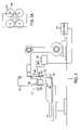
- FIG. 4illustrates a collision avoidance subsystem 300 , constructed in accordance with another embodiment of the present invention, and including an array 310 of acoustic transducers 320 .
- the exclusion zone 140is implemented via the array of acoustic transducers 320 .
- the transducers 320are capable of determining the distance to the nearest object, preferably at 6 to 80 inches therefrom. In one form, the transducers 320 ping to determined the distance to the nearest object.
- the acoustic transducers 320may be ultrasonic transducers, by way of example.
- the array 310 of acoustic transducers 320is fixedly coupled to the x-ray emission head of the linac 104 .
- Each of the transducers 320transmits a succession of acoustic pulses 322 along a transmission axis 330 extending from the linac 104 .
- Each transducerdetects acoustic energy back-scattered along the transmission axis 330 from any object disposed along the transmission axis.
- the subsystem 300includes software for mutually aligning the beam axes (prior to operation of the subsystem 300 ), whereby cross-sections of adjacent pairs of pulses 322 transverse to the transmission axis 330 are contiguous at a predetermined distance from the head 105 to minimize gaps in the covered area.
- the collision avoidance subsystem 300includes software 301 for determining, from the received back-scattered acoustic energy, the distance between the linac and the object. In response to the determined distance being at or less than a predetermined value, the software sends signals to the controller 108 , instructing the controller to interrupt any further motion of the head 105 toward the exclusion zone 140 .
- an array of four ultrasonic transducers 320are arranged about the base of the linac 104 in a rectangular pattern, as shown in FIG. 5A .
- the acoustic pulses 322form a sense cone 340 , as illustrated in FIGS. 5A and 5B .
- the four ultrasonic sensors 320are arranged around the housing of the collimator 107 , so as to provide full coverage of the collimator at 24 inches.
- two of the sensors 320are mounted on a base plate 360 of the linac 104 , via existing holes 361 in the base plate 360 .
- Two sensorsare mounted on the cover 380 of the linac 104 .
- the coverthus includes three holes that are cut therein, two holes 381 for the sensors and one hole 382 for wire exit.
- Each ultrasonic sensor 320determines the distance from the nearest object, when such distance ranges from 6 to 80 inches. Each sensor reports an analog voltage value corresponding to the sensed distance, ranging from 0 to 10 volts: 0 volts indicates 6 inches to the nearest object, whereas 10 volts indicates 80 inches to the nearest object. Each sensor pings at 150 KHz, with a response time of 25 milliseconds, and is able to discern objects at plus or minus 10 degrees from the perpendicular view angle. Before operation, the input of all four sensors 320 are synchronized, in order to prevent crosstalk between the sensors. The sensors 320 may be connected to the analog input on the robot 102 . In one form, the sensors may be manually disabled by a switch.
- FIG. 6illustrates a collision avoidance subsystem 400 , constructed in accordance with another embodiment of the present invention, and including a tactile sensor.
- the present inventionimplements the exclusion zone 140 with a sensor 430 , which generates an indicative signal if and when it impacts with an object in the exclusion zone 140 .
- the sensor 430is a tactile sensor, such as a pressure-sensitive pad; however, other types of sensors (including but not limited to infrared sensors and electrostatic capacitance sensors) may be used in other embodiments of the invention.
- the tactile sensor 430is disposed on a surface 422 of the articulated arm assembly 112 of the robot 102 .
- the sensor 430is operative to generate an alarm signal upon impact of sensor 430 with any object, during motion of the arm 112 and/or head 105 .
- the tactile sensor 430includes a fluid-filled bladder 432 , and a pressure transducer 434 coupled to the bladder 432 for generating the alarm signal, when fluid pressure in the bladder 432 exceeds a predetermined threshold.
- the controller 108includes software, responsive to the alarm signal, for sending instructions to the robot to interrupt any further motion of the arm 112 and/or head 105 .
- the collision avoidance subsystemsmay include software filters on the return signal, for minimizing false positive signals.
Landscapes
- Health & Medical Sciences (AREA)
- Engineering & Computer Science (AREA)
- Biomedical Technology (AREA)
- Pathology (AREA)
- Nuclear Medicine, Radiotherapy & Molecular Imaging (AREA)
- Radiology & Medical Imaging (AREA)
- Life Sciences & Earth Sciences (AREA)
- Animal Behavior & Ethology (AREA)
- General Health & Medical Sciences (AREA)
- Public Health (AREA)
- Veterinary Medicine (AREA)
- Human Computer Interaction (AREA)
- Manufacturing & Machinery (AREA)
- Physics & Mathematics (AREA)
- General Physics & Mathematics (AREA)
- Automation & Control Theory (AREA)
- Radiation-Therapy Devices (AREA)
Abstract
Description
Claims (64)
Priority Applications (7)
| Application Number | Priority Date | Filing Date | Title |
|---|---|---|---|
| US10/814,451US7046765B2 (en) | 2004-03-31 | 2004-03-31 | Radiosurgery x-ray system with collision avoidance subsystem |
| EP07114471AEP1872829A3 (en) | 2004-03-31 | 2005-03-15 | Radiosurgery x-ray system with collision avoidance subsystem |
| PCT/US2005/008658WO2005099820A1 (en) | 2004-03-31 | 2005-03-15 | Radiosurgery x-ray system with collision avoidance subsystem |
| EP07114470AEP1872828A3 (en) | 2004-03-31 | 2005-03-15 | Radiosurgery x-ray system with collision avoidance subsystem |
| EP05725677AEP1729850A4 (en) | 2004-03-31 | 2005-03-15 | Radiosurgery x-ray system with collision avoidance subsystem |
| US11/338,120US7103144B2 (en) | 2004-03-31 | 2006-01-23 | Radiosurgery X-ray system with collision avoidance subsystem |
| US11/338,123US7103145B2 (en) | 2004-03-31 | 2006-01-23 | Radiosurgery x-ray system with collision avoidance subsystem |
Applications Claiming Priority (1)
| Application Number | Priority Date | Filing Date | Title |
|---|---|---|---|
| US10/814,451US7046765B2 (en) | 2004-03-31 | 2004-03-31 | Radiosurgery x-ray system with collision avoidance subsystem |
Related Child Applications (2)
| Application Number | Title | Priority Date | Filing Date |
|---|---|---|---|
| US11/338,123ContinuationUS7103145B2 (en) | 2004-03-31 | 2006-01-23 | Radiosurgery x-ray system with collision avoidance subsystem |
| US11/338,120ContinuationUS7103144B2 (en) | 2004-03-31 | 2006-01-23 | Radiosurgery X-ray system with collision avoidance subsystem |
Publications (2)
| Publication Number | Publication Date |
|---|---|
| US20050226377A1 US20050226377A1 (en) | 2005-10-13 |
| US7046765B2true US7046765B2 (en) | 2006-05-16 |
Family
ID=35060539
Family Applications (3)
| Application Number | Title | Priority Date | Filing Date |
|---|---|---|---|
| US10/814,451Expired - LifetimeUS7046765B2 (en) | 2004-03-31 | 2004-03-31 | Radiosurgery x-ray system with collision avoidance subsystem |
| US11/338,123Expired - LifetimeUS7103145B2 (en) | 2004-03-31 | 2006-01-23 | Radiosurgery x-ray system with collision avoidance subsystem |
| US11/338,120ActiveUS7103144B2 (en) | 2004-03-31 | 2006-01-23 | Radiosurgery X-ray system with collision avoidance subsystem |
Family Applications After (2)
| Application Number | Title | Priority Date | Filing Date |
|---|---|---|---|
| US11/338,123Expired - LifetimeUS7103145B2 (en) | 2004-03-31 | 2006-01-23 | Radiosurgery x-ray system with collision avoidance subsystem |
| US11/338,120ActiveUS7103144B2 (en) | 2004-03-31 | 2006-01-23 | Radiosurgery X-ray system with collision avoidance subsystem |
Country Status (3)
| Country | Link |
|---|---|
| US (3) | US7046765B2 (en) |
| EP (3) | EP1872828A3 (en) |
| WO (1) | WO2005099820A1 (en) |
Cited By (43)
| Publication number | Priority date | Publication date | Assignee | Title |
|---|---|---|---|---|
| US20050161051A1 (en)* | 2003-01-08 | 2005-07-28 | Cyberheart, Inc. | System for non-invasive heart treatment |
| US20050197564A1 (en)* | 2004-02-20 | 2005-09-08 | University Of Florida Research Foundation, Inc. | System for delivering conformal radiation therapy while simultaneously imaging soft tissue |
| US20050228255A1 (en)* | 2004-04-06 | 2005-10-13 | Michael Saracen | Patient positioning assembly |
| US20050234327A1 (en)* | 2004-04-06 | 2005-10-20 | Saracen Michael J | Robotic arm for patient positioning assembly |
| US20060074292A1 (en)* | 2004-09-30 | 2006-04-06 | Accuray, Inc. | Dynamic tracking of moving targets |
| US20060184275A1 (en)* | 2003-03-25 | 2006-08-17 | Hirofumi Hosokawa | Robot simulation device, and robot simulation program |
| US20060245543A1 (en)* | 2003-10-17 | 2006-11-02 | Eric Earnst | Patient positioning assembly for therapeutic radiation system |
| US20060274888A1 (en)* | 2005-05-19 | 2006-12-07 | Philipp Bernhardt | Medical imaging system with a part which can be moved about a patient and a collision protection method |
| US20070140429A1 (en)* | 2005-05-12 | 2007-06-21 | Martin Hoheisel | Method for monitoring an x-ray apparatus and x-ray apparatus |
| US20070211861A1 (en)* | 2006-03-10 | 2007-09-13 | Detlef Koertge | Collision resolution in X-ray imaging systems |
| US20080021300A1 (en)* | 2006-06-29 | 2008-01-24 | Allison John W | Four-dimensional target modeling and radiation treatment |
| US20080089481A1 (en)* | 2006-10-16 | 2008-04-17 | Oraya Therapeutics, Inc. | Portable orthovoltage radiotherapy |
| US20080212738A1 (en)* | 2006-12-13 | 2008-09-04 | Oraya Therapeutics, Inc. | Orthovoltage radiotherapy |
| US20090161826A1 (en)* | 2007-12-23 | 2009-06-25 | Oraya Therapeutics, Inc. | Methods and devices for orthovoltage ocular radiotherapy and treatment planning |
| US20090161827A1 (en)* | 2007-12-23 | 2009-06-25 | Oraya Therapeutics, Inc. | Methods and devices for detecting, controlling, and predicting radiation delivery |
| US20090163898A1 (en)* | 2007-06-04 | 2009-06-25 | Oraya Therapeutics, Inc. | Method and device for ocular alignment and coupling of ocular structures |
| US20090182310A1 (en)* | 2008-01-11 | 2009-07-16 | Oraya Therapeutics, Inc. | System and method for performing an ocular irradiation procedure |
| US20100204713A1 (en)* | 2006-02-03 | 2010-08-12 | The European Atomic Energy Community (Euratom) | Medical robotic system |
| US8005571B2 (en) | 2002-08-13 | 2011-08-23 | Neuroarm Surgical Ltd. | Microsurgical robot system |
| US20110249088A1 (en)* | 2010-04-13 | 2011-10-13 | Varian Medical Systems, Inc. | Systems and methods for monitoring radiation treatment |
| EP2418507A1 (en) | 2010-08-11 | 2012-02-15 | Elekta AB (PUBL) | sensor array |
| US20130298329A1 (en)* | 2012-05-14 | 2013-11-14 | Hanns Eder | Patient support apparatus, a medical imaging apparatus with the patient support apparatus and a method for marking a maximum occupancy area |
| US8750453B2 (en) | 2003-08-12 | 2014-06-10 | Loma Linda University Medical Center | Path planning and collision avoidance for movement of instruments in a radiation therapy environment |
| US8792614B2 (en) | 2009-03-31 | 2014-07-29 | Matthew R. Witten | System and method for radiation therapy treatment planning using a memetic optimization algorithm |
| US9259282B2 (en) | 2012-12-10 | 2016-02-16 | Intuitive Surgical Operations, Inc. | Collision avoidance during controlled movement of image capturing device and manipulatable device movable arms |
| US9486647B2 (en) | 2012-04-27 | 2016-11-08 | Elekta Ab (Publ) | Vision system for radiotherapy machine control |
| US9966160B2 (en) | 2015-11-24 | 2018-05-08 | Viewray Technologies, Inc. | Radiation beam collimating systems and methods |
| US20180185106A1 (en)* | 2014-03-17 | 2018-07-05 | Intuitive Surgical Operations, Inc. | Surgical system with obstacle indication system |
| US10212800B2 (en)* | 2017-03-24 | 2019-02-19 | Radiabeam Technologies, Llc | Compact linear accelerator with accelerating waveguide |
| US10272265B2 (en) | 2016-04-01 | 2019-04-30 | Varian Medical Systems International Ag | Collision avoidance for radiation therapy |
| US10413751B2 (en) | 2016-03-02 | 2019-09-17 | Viewray Technologies, Inc. | Particle therapy with magnetic resonance imaging |
| US20190329073A1 (en)* | 2016-12-23 | 2019-10-31 | Koninklijke Philips N.V. | Ray tracing for the detection and avoidance of collisions between radiotherapy devices and patient |
| US10463884B2 (en) | 2013-03-15 | 2019-11-05 | Viewray Technologies, Inc. | Systems and methods for linear accelerator radiotherapy with magnetic resonance imaging |
| US10549116B2 (en) | 2015-03-05 | 2020-02-04 | The Regents Of The University Of California | Radiotherapy utilizing the entire 4PI solid angle |
| US10561861B2 (en) | 2012-05-02 | 2020-02-18 | Viewray Technologies, Inc. | Videographic display of real-time medical treatment |
| US10821303B2 (en) | 2012-10-26 | 2020-11-03 | Viewray Technologies, Inc. | Assessment and improvement of treatment using imaging of physiological responses to radiation therapy |
| US10932354B2 (en) | 2017-06-01 | 2021-02-23 | Radiabeam Technologies, Llc | Split structure particle accelerators |
| US11000706B2 (en) | 2016-12-13 | 2021-05-11 | Viewray Technologies, Inc. | Radiation therapy systems and methods |
| US11033758B2 (en) | 2017-12-06 | 2021-06-15 | Viewray Technologies, Inc. | Radiotherapy systems, methods and software |
| US11209509B2 (en) | 2018-05-16 | 2021-12-28 | Viewray Technologies, Inc. | Resistive electromagnet systems and methods |
| US11378629B2 (en) | 2016-06-22 | 2022-07-05 | Viewray Technologies, Inc. | Magnetic resonance imaging |
| US11540382B2 (en) | 2017-05-05 | 2022-12-27 | Radiabeam Technologies, Llc | Compact high gradient ion accelerating structure |
| US11612049B2 (en) | 2018-09-21 | 2023-03-21 | Radiabeam Technologies, Llc | Modified split structure particle accelerators |
Families Citing this family (43)
| Publication number | Priority date | Publication date | Assignee | Title |
|---|---|---|---|---|
| CA2465511C (en) | 2001-10-30 | 2007-12-18 | Loma Linda University Medical Center | Method and device for delivering radiotherapy |
| WO2004009303A1 (en)* | 2002-07-18 | 2004-01-29 | Kabushiki Kaisha Yaskawa Denki | Robot controller and robot system |
| US7046765B2 (en) | 2004-03-31 | 2006-05-16 | Accuray, Inc. | Radiosurgery x-ray system with collision avoidance subsystem |
| US7397044B2 (en)* | 2005-07-21 | 2008-07-08 | Siemens Medical Solutions Usa, Inc. | Imaging mode for linear accelerators |
| DE102005049106A1 (en)* | 2005-10-13 | 2007-04-19 | Siemens Ag | Medical imaging system and collision protection method with adjustable arm |
| US20070189455A1 (en)* | 2006-02-14 | 2007-08-16 | Accuray Incorporated | Adaptive x-ray control |
| US7702073B2 (en)* | 2006-09-12 | 2010-04-20 | Morpho Detection, Inc. | Systems and methods for developing a secondary collimator |
| US8727618B2 (en)* | 2006-11-22 | 2014-05-20 | Siemens Aktiengesellschaft | Robotic device and method for trauma patient diagnosis and therapy |
| USD570487S1 (en)* | 2007-03-01 | 2008-06-03 | Siemens Aktiengesellschaft | Robotic positioning device for a patient table |
| US20090012509A1 (en)* | 2007-04-24 | 2009-01-08 | Medtronic, Inc. | Navigated Soft Tissue Penetrating Laser System |
| US8311611B2 (en)* | 2007-04-24 | 2012-11-13 | Medtronic, Inc. | Method for performing multiple registrations in a navigated procedure |
| US8734466B2 (en)* | 2007-04-25 | 2014-05-27 | Medtronic, Inc. | Method and apparatus for controlled insertion and withdrawal of electrodes |
| US8301226B2 (en)* | 2007-04-24 | 2012-10-30 | Medtronic, Inc. | Method and apparatus for performing a navigated procedure |
| US8108025B2 (en)* | 2007-04-24 | 2012-01-31 | Medtronic, Inc. | Flexible array for use in navigated surgery |
| US9289270B2 (en)* | 2007-04-24 | 2016-03-22 | Medtronic, Inc. | Method and apparatus for performing a navigated procedure |
| CA2737938C (en)* | 2007-09-19 | 2016-09-13 | Walter A. Roberts | Direct visualization robotic intra-operative radiation therapy applicator device |
| WO2010030397A1 (en)* | 2008-09-12 | 2010-03-18 | Accuray Incorporated | Controlling x-ray imaging based on target motion |
| US8934605B2 (en) | 2010-02-24 | 2015-01-13 | Accuray Incorporated | Gantry image guided radiotherapy system and related treatment delivery methods |
| DE102010010875A1 (en)* | 2010-03-10 | 2011-09-15 | Siemens Aktiengesellschaft | Method for monitoring the spatial environment of a movable device, in particular a medical device |
| US8855812B2 (en)* | 2010-07-23 | 2014-10-07 | Chetan Kapoor | System and method for robot safety and collision avoidance |
| US8989846B2 (en)* | 2010-08-08 | 2015-03-24 | Accuray Incorporated | Radiation treatment delivery system with outwardly movable radiation treatment head extending from ring gantry |
| MX342614B (en)* | 2011-12-01 | 2016-10-06 | Koninklijke Philips Nv | Medical imaging system and method for providing an x-ray image. |
| CN105072983B (en)* | 2013-02-22 | 2018-05-15 | 皇家飞利浦有限公司 | Thermotherapy for diagnosing image |
| CN104416581A (en)* | 2013-08-27 | 2015-03-18 | 富泰华工业(深圳)有限公司 | Mechanical arm with warning function |
| EP2927942A1 (en)* | 2014-04-04 | 2015-10-07 | Nordson Corporation | X-ray inspection apparatus for inspecting semiconductor wafers |
| US9958862B2 (en) | 2014-05-08 | 2018-05-01 | Yaskawa America, Inc. | Intuitive motion coordinate system for controlling an industrial robot |
| US10188358B2 (en) | 2014-05-15 | 2019-01-29 | General Electric Company | System and method for subject shape estimation |
| DE102014011012A1 (en)* | 2014-07-24 | 2016-01-28 | Kuka Roboter Gmbh | Method and means for designing and / or operating a robot |
| WO2017127202A1 (en) | 2016-01-20 | 2017-07-27 | Intuitive Surgical Operations, Inc. | System and method for rapid halt and recovery of motion deviations in medical device repositionable arms |
| EP3199106B1 (en)* | 2017-04-26 | 2020-09-09 | Siemens Healthcare GmbH | Method and device for ultrasound inspection |
| JP2019188556A (en)* | 2018-04-26 | 2019-10-31 | オムロン株式会社 | Sensor controller, robot system, sensor control method, and program |
| US12026832B2 (en) | 2018-06-08 | 2024-07-02 | Data Integrity Advisors, Llc | System and method for gating radiation exposure |
| DE102018123363B4 (en)* | 2018-09-24 | 2021-01-07 | Bystronic Laser Ag | Procedure for collision avoidance and laser processing machine |
| DE102018125620A1 (en)* | 2018-10-16 | 2020-04-16 | Schuler Pressen Gmbh | Method and device for cutting a sheet metal blank from a continuously conveyed sheet metal strip |
| WO2020142560A1 (en)* | 2019-01-02 | 2020-07-09 | Yifat Jonathan | Supplementary collision detection and prevention system for a medical imager |
| JP6758441B2 (en)* | 2019-02-18 | 2020-09-23 | 株式会社アマダ | Laser processing machine, laser processing method, and processing program creation device |
| WO2020218496A1 (en)* | 2019-04-24 | 2020-10-29 | 国立研究開発法人国立成育医療研究センター | Measurement device, measurement method, and radiation projecting device |
| CN110441336B (en)* | 2019-08-27 | 2024-01-02 | 江苏金恒信息科技股份有限公司 | Flexible contact device of alloy analyzer |
| WO2021102587A1 (en)* | 2019-11-29 | 2021-06-03 | Innovere Medical Inc. | Systems and methods for passive collision control during medical imaging or therapeutic procedures |
| DE102021116899A1 (en)* | 2021-06-30 | 2023-01-05 | Messer Cutting Systems Gmbh | Process for thermal processing of a workpiece with a thermal processing machine |
| CN117980036A (en)* | 2021-07-20 | 2024-05-03 | 美国迈胜医疗系统有限公司 | Rack with retractable cover |
| JP7739113B2 (en)* | 2021-09-29 | 2025-09-16 | 株式会社日立ハイテク | Radiation therapy system and method for operating a radiation therapy system |
| CN115227272A (en)* | 2022-08-05 | 2022-10-25 | 北京唯迈医疗设备有限公司 | A comprehensive omnidirectional DSA collision avoidance system and method |
Citations (7)
| Publication number | Priority date | Publication date | Assignee | Title |
|---|---|---|---|---|
| US5207223A (en) | 1990-10-19 | 1993-05-04 | Accuray, Inc. | Apparatus for and method of performing stereotaxic surgery |
| US5427097A (en) | 1992-12-10 | 1995-06-27 | Accuray, Inc. | Apparatus for and method of carrying out stereotaxic radiosurgery and radiotherapy |
| US5485502A (en)* | 1994-07-26 | 1996-01-16 | Lunar Corporation | Radiographic gantry with software collision avoidance |
| US5878112A (en)* | 1996-06-25 | 1999-03-02 | Siemens Aktiengesellschaft | Medical system having movable components and a control device for preventing component collisions |
| US6272368B1 (en)* | 1997-10-01 | 2001-08-07 | Siemens Aktiengesellschaft | Medical installation having an apparatus for acquiring the position of at least one object located in a room |
| US6651279B1 (en) | 2002-11-26 | 2003-11-25 | Ge Medical Systems Global Technology Company, Llc | Method and apparatus for collision avoidance in a patient positioning platform |
| US6784828B2 (en) | 2000-08-16 | 2004-08-31 | Raytheon Company | Near object detection system |
Family Cites Families (10)
| Publication number | Priority date | Publication date | Assignee | Title |
|---|---|---|---|---|
| US3777124A (en)* | 1970-11-27 | 1973-12-04 | Varian Associates | Computer assisted radiation therapy machine |
| SE456048B (en)* | 1982-02-24 | 1988-08-29 | Philips Norden Ab | SET AND DEVICE FOR DETERMINING THE RISK OF COLLISION FOR TWO INBOARD'S LOVELY BODIES |
| DE3604955C2 (en)* | 1986-02-17 | 1994-03-24 | Siemens Ag | X-ray diagnostic device |
| DE3840677A1 (en)* | 1988-12-02 | 1990-06-07 | Krupp Atlas Elektronik Gmbh | OPTICAL MONITORING SENSOR |
| US5625191A (en)* | 1992-10-28 | 1997-04-29 | Kabushiki Kaisha Toshiba | Scintillation camera and sensor for use therein |
| US5805275A (en)* | 1993-04-08 | 1998-09-08 | Kollmorgen Corporation | Scanning optical rangefinder |
| US6956196B2 (en)* | 2000-04-11 | 2005-10-18 | Oncology Automation, Inc. | Systems for maintaining the spatial position of an object and related methods |
| US6927395B2 (en)* | 2002-06-14 | 2005-08-09 | Koninklijke Philips Electronics N.V. | Gamma camera collision avoidance |
| DE10231630A1 (en)* | 2002-07-12 | 2004-01-29 | Brainlab Ag | System for patient positioning for radiotherapy / radiosurgery based on a stereoscopic x-ray system |
| US7046765B2 (en) | 2004-03-31 | 2006-05-16 | Accuray, Inc. | Radiosurgery x-ray system with collision avoidance subsystem |
- 2004
- 2004-03-31USUS10/814,451patent/US7046765B2/ennot_activeExpired - Lifetime
- 2005
- 2005-03-15EPEP07114470Apatent/EP1872828A3/ennot_activeWithdrawn
- 2005-03-15WOPCT/US2005/008658patent/WO2005099820A1/ennot_activeApplication Discontinuation
- 2005-03-15EPEP07114471Apatent/EP1872829A3/ennot_activeWithdrawn
- 2005-03-15EPEP05725677Apatent/EP1729850A4/ennot_activeWithdrawn
- 2006
- 2006-01-23USUS11/338,123patent/US7103145B2/ennot_activeExpired - Lifetime
- 2006-01-23USUS11/338,120patent/US7103144B2/enactiveActive
Patent Citations (7)
| Publication number | Priority date | Publication date | Assignee | Title |
|---|---|---|---|---|
| US5207223A (en) | 1990-10-19 | 1993-05-04 | Accuray, Inc. | Apparatus for and method of performing stereotaxic surgery |
| US5427097A (en) | 1992-12-10 | 1995-06-27 | Accuray, Inc. | Apparatus for and method of carrying out stereotaxic radiosurgery and radiotherapy |
| US5485502A (en)* | 1994-07-26 | 1996-01-16 | Lunar Corporation | Radiographic gantry with software collision avoidance |
| US5878112A (en)* | 1996-06-25 | 1999-03-02 | Siemens Aktiengesellschaft | Medical system having movable components and a control device for preventing component collisions |
| US6272368B1 (en)* | 1997-10-01 | 2001-08-07 | Siemens Aktiengesellschaft | Medical installation having an apparatus for acquiring the position of at least one object located in a room |
| US6784828B2 (en) | 2000-08-16 | 2004-08-31 | Raytheon Company | Near object detection system |
| US6651279B1 (en) | 2002-11-26 | 2003-11-25 | Ge Medical Systems Global Technology Company, Llc | Method and apparatus for collision avoidance in a patient positioning platform |
Non-Patent Citations (2)
| Title |
|---|
| "PCT International Search Report", International Searching Authority, Jun. 21, 2005, PCT/US05/08658, 3 pgs. |
| "PCT Written Opinion of the International Searching Authority", International Searching Authority, Jun. 21, 2005, PCT/US05/08658, 5 pgs. |
Cited By (172)
| Publication number | Priority date | Publication date | Assignee | Title |
|---|---|---|---|---|
| US9220567B2 (en) | 2002-08-13 | 2015-12-29 | Neuroarm Surgical Ltd. | Microsurgical robot system |
| US8041459B2 (en) | 2002-08-13 | 2011-10-18 | Neuroarm Surgical Ltd. | Methods relating to microsurgical robot system |
| US8005571B2 (en) | 2002-08-13 | 2011-08-23 | Neuroarm Surgical Ltd. | Microsurgical robot system |
| US8396598B2 (en) | 2002-08-13 | 2013-03-12 | Neuroarm Surgical Ltd. | Microsurgical robot system |
| US8170717B2 (en) | 2002-08-13 | 2012-05-01 | Neuroarm Surgical Ltd. | Microsurgical robot system |
| US11305132B2 (en) | 2003-01-08 | 2022-04-19 | Varian Medical Systems, Inc. | System for non-invasive heart treatment |
| US20100160775A1 (en)* | 2003-01-08 | 2010-06-24 | Cyberheart, Inc. | System For Non-Invasive Heart Treatment |
| US7645276B2 (en)* | 2003-01-08 | 2010-01-12 | Cyberheart, Inc. | System for non-invasive heart treatment |
| US20050161051A1 (en)* | 2003-01-08 | 2005-07-28 | Cyberheart, Inc. | System for non-invasive heart treatment |
| US8696658B2 (en) | 2003-01-08 | 2014-04-15 | Cyberheart, Inc. | System for non-invasive heart treatment |
| US10792511B2 (en) | 2003-01-08 | 2020-10-06 | Cyberheart, Inc. | System for non-invasive heart treatment |
| US7606633B2 (en)* | 2003-03-25 | 2009-10-20 | Rorze Corporation | Robot simulation device, and robot simulation program |
| US20060184275A1 (en)* | 2003-03-25 | 2006-08-17 | Hirofumi Hosokawa | Robot simulation device, and robot simulation program |
| US8750453B2 (en) | 2003-08-12 | 2014-06-10 | Loma Linda University Medical Center | Path planning and collision avoidance for movement of instruments in a radiation therapy environment |
| US10010720B2 (en) | 2003-08-12 | 2018-07-03 | Vision Rt Limited | Path planning and collision avoidance for movement of instruments in a radiation therapy environment |
| US9623263B2 (en) | 2003-08-12 | 2017-04-18 | Vision Rt Limited | Path planning and collision avoidance for movement of instruments in a radiation therapy environment |
| US20060245543A1 (en)* | 2003-10-17 | 2006-11-02 | Eric Earnst | Patient positioning assembly for therapeutic radiation system |
| US7907987B2 (en) | 2004-02-20 | 2011-03-15 | University Of Florida Research Foundation, Inc. | System for delivering conformal radiation therapy while simultaneously imaging soft tissue |
| US11497937B2 (en) | 2004-02-20 | 2022-11-15 | University Of Florida Research Foundation, Inc. | System for delivering conformal radiation therapy while simultaneously imaging soft tissue |
| US20050197564A1 (en)* | 2004-02-20 | 2005-09-08 | University Of Florida Research Foundation, Inc. | System for delivering conformal radiation therapy while simultaneously imaging soft tissue |
| US8190233B2 (en) | 2004-02-20 | 2012-05-29 | University Of Florida Research Foundation, Inc. | System for delivering conformal radiation therapy while simultaneously imaging soft tissue |
| US10688319B2 (en) | 2004-02-20 | 2020-06-23 | University Of Florida Research Foundation, Inc. | System for delivering conformal radiation therapy while simultaneously imaging soft tissue |
| US20100113911A1 (en)* | 2004-02-20 | 2010-05-06 | University Of Florida Research Foundation, Inc. | System for Delivering Conformal Radiation Therapy While Simultaneously Imaging Soft Tissue |
| US10745253B2 (en) | 2004-04-06 | 2020-08-18 | Accuray Incorporated | Robotic arm for patient positioning assembly |
| US7860550B2 (en) | 2004-04-06 | 2010-12-28 | Accuray, Inc. | Patient positioning assembly |
| US8160205B2 (en) | 2004-04-06 | 2012-04-17 | Accuray Incorporated | Robotic arm for patient positioning assembly |
| US20050228255A1 (en)* | 2004-04-06 | 2005-10-13 | Michael Saracen | Patient positioning assembly |
| US8457279B2 (en) | 2004-04-06 | 2013-06-04 | Accuray Incorporated | Patient positioning assembly |
| US20100237257A1 (en)* | 2004-04-06 | 2010-09-23 | Accuray. Inc. | Patient positioning assembly |
| US20050234327A1 (en)* | 2004-04-06 | 2005-10-20 | Saracen Michael J | Robotic arm for patient positioning assembly |
| US8745789B2 (en) | 2004-04-06 | 2014-06-10 | Accuray Incorporated | Robotic arm for patient positioning assembly |
| US9474914B2 (en) | 2004-09-30 | 2016-10-25 | Accuray Incorporated | Tracking of moving targets |
| US20080039713A1 (en)* | 2004-09-30 | 2008-02-14 | Euan Thomson | Dynamic tracking of moving targets |
| US8874187B2 (en) | 2004-09-30 | 2014-10-28 | Accuray Inc. | Dynamic tracking of moving targets |
| US8989349B2 (en) | 2004-09-30 | 2015-03-24 | Accuray, Inc. | Dynamic tracking of moving targets |
| US20060074292A1 (en)* | 2004-09-30 | 2006-04-06 | Accuray, Inc. | Dynamic tracking of moving targets |
| US20070140429A1 (en)* | 2005-05-12 | 2007-06-21 | Martin Hoheisel | Method for monitoring an x-ray apparatus and x-ray apparatus |
| US7290930B2 (en)* | 2005-05-12 | 2007-11-06 | Siemens Aktiengesellschaft | Method for monitoring an x-ray apparatus and x-ray apparatus |
| US20060274888A1 (en)* | 2005-05-19 | 2006-12-07 | Philipp Bernhardt | Medical imaging system with a part which can be moved about a patient and a collision protection method |
| US7428296B2 (en)* | 2005-05-19 | 2008-09-23 | Siemens Aktiengesellschaft | Medical imaging system with a part which can be moved about a patient and a collision protection method |
| US20100204713A1 (en)* | 2006-02-03 | 2010-08-12 | The European Atomic Energy Community (Euratom) | Medical robotic system |
| US9358682B2 (en)* | 2006-02-03 | 2016-06-07 | The European Atomic Energy Community (Euratom), Represented By The European Commission | Medical robotic system |
| US20070211861A1 (en)* | 2006-03-10 | 2007-09-13 | Detlef Koertge | Collision resolution in X-ray imaging systems |
| US7379533B2 (en) | 2006-03-10 | 2008-05-27 | Siemens Medical Solutions Usa, Inc. | Collision resolution in x-ray imaging systems |
| US20080021300A1 (en)* | 2006-06-29 | 2008-01-24 | Allison John W | Four-dimensional target modeling and radiation treatment |
| US8995618B2 (en) | 2006-10-16 | 2015-03-31 | Oraya Therapeutics, Inc. | Portable orthovoltage radiotherapy |
| US8837675B2 (en) | 2006-10-16 | 2014-09-16 | Oraya Therapeutics, Inc. | Ocular radiosurgery |
| US7693258B2 (en) | 2006-10-16 | 2010-04-06 | Oraya Therapeutics, Inc. | Orthovoltage radiotherapy |
| US7693259B2 (en) | 2006-10-16 | 2010-04-06 | Oraya Therapeutics, Inc. | Orthovoltage radiotherapy |
| US7697663B2 (en) | 2006-10-16 | 2010-04-13 | Oraya Therapeutics, Inc. | Orthovoltage radiotherapy |
| US8855267B2 (en) | 2006-10-16 | 2014-10-07 | Oraya Therapeutics, Inc. | Orthovoltage radiosurgery |
| US7680245B2 (en) | 2006-10-16 | 2010-03-16 | Oraya Therapeutics, Inc. | Orthovoltage radiotherapy |
| US8761336B2 (en) | 2006-10-16 | 2014-06-24 | Oraya Therapeutics, Inc. | Orthovoltage radiotherapy |
| US20100195794A1 (en)* | 2006-10-16 | 2010-08-05 | Oraya Therapeutics, Inc. | Orthovoltage radiotherapy |
| US7680244B2 (en) | 2006-10-16 | 2010-03-16 | Oraya Therapeutics, Inc. | Ocular radiosurgery |
| US7564946B2 (en) | 2006-10-16 | 2009-07-21 | Oraya Therapeutics, Inc. | Orthovoltage radiotherapy |
| US7535991B2 (en) | 2006-10-16 | 2009-05-19 | Oraya Therapeutics, Inc. | Portable orthovoltage radiotherapy |
| US7496174B2 (en) | 2006-10-16 | 2009-02-24 | Oraya Therapeutics, Inc. | Portable orthovoltage radiotherapy |
| US20100254513A1 (en)* | 2006-10-16 | 2010-10-07 | Oraya Therapeutics, Inc. | Orthovoltage radiotherapy |
| US20100260320A1 (en)* | 2006-10-16 | 2010-10-14 | Oraya Therapeutics, Inc. | Orthovoltage radiotherapy |
| US7822175B2 (en) | 2006-10-16 | 2010-10-26 | Oraya Therapeutics, Inc. | Portable orthovoltage radiotherapy |
| US20080192893A1 (en)* | 2006-10-16 | 2008-08-14 | Oraya Therapeutics, Inc. | Orthovoltage radiotherapy |
| US20080187100A1 (en)* | 2006-10-16 | 2008-08-07 | Oraya Therapeutics, Inc. | Orthovoltage radiotherapy |
| US7912178B2 (en) | 2006-10-16 | 2011-03-22 | Oraya Therapeutics, Inc. | Orthovoltage radiotherapy |
| US20080187101A1 (en)* | 2006-10-16 | 2008-08-07 | Oraya Therapeutics, Inc. | Orthovoltage radiotherapy |
| US8611497B2 (en) | 2006-10-16 | 2013-12-17 | Oraya Therapeutics, Inc. | Portable orthovoltage radiotherapy |
| US20080187102A1 (en)* | 2006-10-16 | 2008-08-07 | Oraya Therapeutics, Inc. | Orthovoltage radiotherapy |
| US8442185B2 (en) | 2006-10-16 | 2013-05-14 | Oraya Therapeutics, Inc. | Orthovoltage radiosurgery |
| US20080187099A1 (en)* | 2006-10-16 | 2008-08-07 | Oraya Therapeutics, Inc. | Orthovoltage radiotherapy |
| US8320524B2 (en) | 2006-10-16 | 2012-11-27 | Oraya Therapeutics, Inc. | Orthovoltage radiotherapy |
| US20110170664A1 (en)* | 2006-10-16 | 2011-07-14 | Oraya Therapeutics, Inc. | Orthovoltage radiosurgery |
| US20080187098A1 (en)* | 2006-10-16 | 2008-08-07 | Oraya Therapeutics, Inc. | Ocular radiosurgery |
| US20080181362A1 (en)* | 2006-10-16 | 2008-07-31 | Oraya Therapeutics, Inc. | Orthovoltage radiotherapy |
| US20080144771A1 (en)* | 2006-10-16 | 2008-06-19 | Oraya Therapeutics, Inc. | Portable orthovoltage radiotherapy |
| US8059784B2 (en) | 2006-10-16 | 2011-11-15 | Oraya Therapeutics, Inc. | Portable orthovoltage radiotherapy |
| US8073105B2 (en) | 2006-10-16 | 2011-12-06 | Oraya Therapeutics, Inc. | Ocular radiosurgery |
| US8094779B2 (en) | 2006-10-16 | 2012-01-10 | Oraya Therapeutics, Inc. | Orthovoltage radiotherapy |
| US8189739B2 (en) | 2006-10-16 | 2012-05-29 | Oraya Therapeutics, Inc. | Orthovoltage radiotherapy |
| US20080089480A1 (en)* | 2006-10-16 | 2008-04-17 | Oraya Therapeutics, Inc. | Portable orthovoltage radiotherapy |
| US20080089481A1 (en)* | 2006-10-16 | 2008-04-17 | Oraya Therapeutics, Inc. | Portable orthovoltage radiotherapy |
| US8180021B2 (en) | 2006-10-16 | 2012-05-15 | Oraya Therapeutics, Inc. | Orthovoltage radiotherapy |
| US8238517B2 (en) | 2006-12-13 | 2012-08-07 | Oraya Therapeutics, Inc. | Orthovoltage radiotherapy |
| US20080212738A1 (en)* | 2006-12-13 | 2008-09-04 | Oraya Therapeutics, Inc. | Orthovoltage radiotherapy |
| US9272161B2 (en) | 2006-12-13 | 2016-03-01 | Oraya Therapeutics, Inc. | Orthovoltage radiotherapy |
| US8229069B2 (en) | 2006-12-13 | 2012-07-24 | Oraya Therapeutics, Inc. | Orthovoltage radiotherapy |
| US8229073B2 (en) | 2006-12-13 | 2012-07-24 | Oraya Therapeutics, Inc. | Orthovoltage radiotherapy |
| US7620147B2 (en) | 2006-12-13 | 2009-11-17 | Oraya Therapeutics, Inc. | Orthovoltage radiotherapy |
| US8295437B2 (en) | 2006-12-13 | 2012-10-23 | Oraya Therapeutics, Inc. | Orthovoltage radiotherapy |
| US8306186B2 (en) | 2006-12-13 | 2012-11-06 | Oraya Therapeutics, Inc. | Orthovoltage radiotherapy |
| US7978818B2 (en) | 2006-12-13 | 2011-07-12 | Oraya Therapeutics, Inc. | Orthovoltage radiotherapy |
| US20100002837A1 (en)* | 2006-12-13 | 2010-01-07 | Oraya Therapeutics, Inc. | Orthovoltage radiotherapy |
| US7978819B2 (en) | 2006-12-13 | 2011-07-12 | Oraya Therapeutics, Inc. | Orthovoltage radiotherapy |
| US7961845B2 (en) | 2006-12-13 | 2011-06-14 | Oraya Therapeutics, Inc. | Orthovoltage radiotherapy |
| US20100067657A1 (en)* | 2006-12-13 | 2010-03-18 | Oraya Therapeutics, Inc. | Orthovoltage radiotherapy |
| US20100067658A1 (en)* | 2006-12-13 | 2010-03-18 | Oraya Therapeutics, Inc. | Orthovoltage radiotherapy |
| US20100067656A1 (en)* | 2006-12-13 | 2010-03-18 | Oraya Therapeutics, Inc. | Orthovoltage radiotherapy |
| US8787524B2 (en) | 2006-12-13 | 2014-07-22 | Oraya Therapeutics, Inc. | Orthovoltage radiotherapy |
| US20100166148A1 (en)* | 2006-12-13 | 2010-07-01 | Oraya Therapeutics, Inc. | Orthovoltage radiotherapy |
| US7953203B2 (en) | 2007-04-09 | 2011-05-31 | Oraya Therapeutics, Inc. | Orthovoltage radiosurgery |
| US7693260B2 (en) | 2007-04-09 | 2010-04-06 | Oraya Therapeutics, Inc. | Orthovoltage radiosurgery |
| US7912179B2 (en) | 2007-04-09 | 2011-03-22 | Oraya Therapeutics, Inc. | Orthovoltage radiosurgery |
| US20090022274A1 (en)* | 2007-04-09 | 2009-01-22 | Oraya Therapeutics, Inc. | Orthovoltage radiosurgery |
| US8184772B2 (en) | 2007-04-09 | 2012-05-22 | Oraya Therapeutics, Inc. | Orthovoltage radiosurgery |
| US20090003525A1 (en)* | 2007-04-09 | 2009-01-01 | Oraya Therapeutics, Inc. | Orthovoltage radiosurgery |
| US8457277B2 (en) | 2007-04-09 | 2013-06-04 | Oraya Therapeutics, Inc. | Orthovoltage radiosurgery |
| US8363783B2 (en) | 2007-06-04 | 2013-01-29 | Oraya Therapeutics, Inc. | Method and device for ocular alignment and coupling of ocular structures |
| US8630388B2 (en) | 2007-06-04 | 2014-01-14 | Oraya Therapeutics, Inc. | Method and device for ocular alignment and coupling of ocular structures |
| US20090163898A1 (en)* | 2007-06-04 | 2009-06-25 | Oraya Therapeutics, Inc. | Method and device for ocular alignment and coupling of ocular structures |
| US8923479B2 (en) | 2007-06-04 | 2014-12-30 | Oraya Therapeutics, Inc. | Method and device for ocular alignment and coupling of ocular structures |
| US8503609B2 (en) | 2007-12-23 | 2013-08-06 | Oraya Therapeutics, Inc. | Methods and devices for detecting, controlling, and predicting radiation delivery |
| US8848869B2 (en) | 2007-12-23 | 2014-09-30 | Oraya Therapeutics, Inc. | Methods and devices for detecting, controlling, and predicting radiation delivery |
| US8494116B2 (en) | 2007-12-23 | 2013-07-23 | Oraya Therapeutics, Inc. | Methods and devices for orthovoltage ocular radiotherapy and treatment planning |
| US20090161826A1 (en)* | 2007-12-23 | 2009-06-25 | Oraya Therapeutics, Inc. | Methods and devices for orthovoltage ocular radiotherapy and treatment planning |
| US7792249B2 (en) | 2007-12-23 | 2010-09-07 | Oraya Therapeutics, Inc. | Methods and devices for detecting, controlling, and predicting radiation delivery |
| US7801271B2 (en) | 2007-12-23 | 2010-09-21 | Oraya Therapeutics, Inc. | Methods and devices for orthovoltage ocular radiotherapy and treatment planning |
| US20090161827A1 (en)* | 2007-12-23 | 2009-06-25 | Oraya Therapeutics, Inc. | Methods and devices for detecting, controlling, and predicting radiation delivery |
| US20110081000A1 (en)* | 2007-12-23 | 2011-04-07 | Oraya Therapeutics, Inc. | Methods and devices for detecting, controlling, and predicting radiation delivery |
| US9025727B2 (en) | 2007-12-23 | 2015-05-05 | Oraya Therapeutics, Inc. | Methods and devices for orthovoltage ocular radiotherapy and treatment planning |
| US8506558B2 (en) | 2008-01-11 | 2013-08-13 | Oraya Therapeutics, Inc. | System and method for performing an ocular irradiation procedure |
| US8920406B2 (en) | 2008-01-11 | 2014-12-30 | Oraya Therapeutics, Inc. | Device and assembly for positioning and stabilizing an eye |
| US20090182311A1 (en)* | 2008-01-11 | 2009-07-16 | Oraya Therapeutics, Inc. | System and method for positioning and stabilizing an eye |
| US20090182312A1 (en)* | 2008-01-11 | 2009-07-16 | Oraya Therapeutics, Inc. | Device and assembly for positioning and stabilizing an eye |
| US20090182310A1 (en)* | 2008-01-11 | 2009-07-16 | Oraya Therapeutics, Inc. | System and method for performing an ocular irradiation procedure |
| US8512236B2 (en) | 2008-01-11 | 2013-08-20 | Oraya Therapeutics, Inc. | System and method for positioning and stabilizing an eye |
| US8792614B2 (en) | 2009-03-31 | 2014-07-29 | Matthew R. Witten | System and method for radiation therapy treatment planning using a memetic optimization algorithm |
| US20110249088A1 (en)* | 2010-04-13 | 2011-10-13 | Varian Medical Systems, Inc. | Systems and methods for monitoring radiation treatment |
| US8730314B2 (en)* | 2010-04-13 | 2014-05-20 | Varian Medical Systems, Inc. | Systems and methods for monitoring radiation treatment |
| EP2418507A1 (en) | 2010-08-11 | 2012-02-15 | Elekta AB (PUBL) | sensor array |
| US9878179B2 (en) | 2012-04-27 | 2018-01-30 | Elekta Ab (Publ) | Vision system for radiotherapy machine control |
| US9486647B2 (en) | 2012-04-27 | 2016-11-08 | Elekta Ab (Publ) | Vision system for radiotherapy machine control |
| US10561861B2 (en) | 2012-05-02 | 2020-02-18 | Viewray Technologies, Inc. | Videographic display of real-time medical treatment |
| US20130298329A1 (en)* | 2012-05-14 | 2013-11-14 | Hanns Eder | Patient support apparatus, a medical imaging apparatus with the patient support apparatus and a method for marking a maximum occupancy area |
| US9289181B2 (en)* | 2012-05-14 | 2016-03-22 | Siemens Aktiengesellschaft | Patient support apparatus, a medical imaging apparatus with the patient support apparatus and a method for marking a maximum occupancy area |
| US11040222B2 (en) | 2012-10-26 | 2021-06-22 | Viewray Technologies, Inc. | Assessment and improvement of treatment using imaging of physiological responses to radiation therapy |
| US10835763B2 (en) | 2012-10-26 | 2020-11-17 | Viewray Technologies, Inc. | Assessment and improvement of treatment using imaging of physiological responses to radiation therapy |
| US10821303B2 (en) | 2012-10-26 | 2020-11-03 | Viewray Technologies, Inc. | Assessment and improvement of treatment using imaging of physiological responses to radiation therapy |
| US10064682B2 (en) | 2012-12-10 | 2018-09-04 | Intuitive Surgical Operations, Inc. | Collision avoidance during controlled movement of image capturing device and manipulatable device movable arms |
| US9259282B2 (en) | 2012-12-10 | 2016-02-16 | Intuitive Surgical Operations, Inc. | Collision avoidance during controlled movement of image capturing device and manipulatable device movable arms |
| US11007023B2 (en) | 2012-12-10 | 2021-05-18 | Intuitive Surgical Operations, Inc. | System and method of registration between devices with movable arms |
| US11612764B2 (en) | 2013-03-15 | 2023-03-28 | Viewray Technologies, Inc. | Systems and methods for linear accelerator radiotherapy with magnetic resonance imaging |
| US11083912B2 (en) | 2013-03-15 | 2021-08-10 | Viewray Technologies, Inc. | Systems and methods for linear accelerator radiotherapy with magnetic resonance imaging |
| US10463884B2 (en) | 2013-03-15 | 2019-11-05 | Viewray Technologies, Inc. | Systems and methods for linear accelerator radiotherapy with magnetic resonance imaging |
| US12376921B2 (en) | 2014-03-17 | 2025-08-05 | Intuitive Surgical Operations, Inc. | Surgical system with obstacle indication system |
| US11793581B2 (en)* | 2014-03-17 | 2023-10-24 | Intuitive Surgical Operations, Inc. | Surgical system with obstacle indication system |
| US20180185106A1 (en)* | 2014-03-17 | 2018-07-05 | Intuitive Surgical Operations, Inc. | Surgical system with obstacle indication system |
| US10549116B2 (en) | 2015-03-05 | 2020-02-04 | The Regents Of The University Of California | Radiotherapy utilizing the entire 4PI solid angle |
| US9966160B2 (en) | 2015-11-24 | 2018-05-08 | Viewray Technologies, Inc. | Radiation beam collimating systems and methods |
| US12017090B2 (en) | 2016-03-02 | 2024-06-25 | Viewray Systems, Inc. | Particle therapy with magnetic resonance imaging |
| US11351398B2 (en) | 2016-03-02 | 2022-06-07 | Viewray Technologies, Inc. | Particle therapy with magnetic resonance imaging |
| US10413751B2 (en) | 2016-03-02 | 2019-09-17 | Viewray Technologies, Inc. | Particle therapy with magnetic resonance imaging |
| US10272265B2 (en) | 2016-04-01 | 2019-04-30 | Varian Medical Systems International Ag | Collision avoidance for radiation therapy |
| US11892523B2 (en) | 2016-06-22 | 2024-02-06 | Viewray Technologies, Inc. | Magnetic resonance imaging |
| US11378629B2 (en) | 2016-06-22 | 2022-07-05 | Viewray Technologies, Inc. | Magnetic resonance imaging |
| US11768257B2 (en) | 2016-06-22 | 2023-09-26 | Viewray Technologies, Inc. | Magnetic resonance imaging |
| US11931602B2 (en) | 2016-12-13 | 2024-03-19 | Viewray Technologies, Inc. | Radiation therapy systems and methods |
| US11000706B2 (en) | 2016-12-13 | 2021-05-11 | Viewray Technologies, Inc. | Radiation therapy systems and methods |
| US20190329073A1 (en)* | 2016-12-23 | 2019-10-31 | Koninklijke Philips N.V. | Ray tracing for the detection and avoidance of collisions between radiotherapy devices and patient |
| US11471702B2 (en)* | 2016-12-23 | 2022-10-18 | Koninklijke Philips N.V. | Ray tracing for a detection and avoidance of collisions between radiotherapy devices and patient |
| US10212800B2 (en)* | 2017-03-24 | 2019-02-19 | Radiabeam Technologies, Llc | Compact linear accelerator with accelerating waveguide |
| US11627653B2 (en) | 2017-03-24 | 2023-04-11 | Radiabeam Technologies, Llc | Compact linear accelerator with accelerating waveguide |
| US20200221567A1 (en)* | 2017-03-24 | 2020-07-09 | Radiabeam Technologies, Llc | Compact linear accelerator with accelerating waveguide |
| US10880985B2 (en)* | 2017-03-24 | 2020-12-29 | Radiabeam Technologies, Llc | Compact linear accelerator with accelerating waveguide |
| US12193141B2 (en) | 2017-05-05 | 2025-01-07 | Radiabeam Technologies, Llc | Compact high gradient ion accelerating structure |
| US11540382B2 (en) | 2017-05-05 | 2022-12-27 | Radiabeam Technologies, Llc | Compact high gradient ion accelerating structure |
| US10932354B2 (en) | 2017-06-01 | 2021-02-23 | Radiabeam Technologies, Llc | Split structure particle accelerators |
| US11950352B2 (en) | 2017-06-01 | 2024-04-02 | Radiabeam Technologies, Llc | Split structure particle accelerators |
| US12432843B2 (en) | 2017-06-01 | 2025-09-30 | Radiabeam Technologies, Llc | Split structure particle accelerators |
| US11033758B2 (en) | 2017-12-06 | 2021-06-15 | Viewray Technologies, Inc. | Radiotherapy systems, methods and software |
| US12000914B2 (en) | 2018-05-16 | 2024-06-04 | Viewray Systems, Inc. | Resistive electromagnet systems and methods |
| US11209509B2 (en) | 2018-05-16 | 2021-12-28 | Viewray Technologies, Inc. | Resistive electromagnet systems and methods |
| US11612049B2 (en) | 2018-09-21 | 2023-03-21 | Radiabeam Technologies, Llc | Modified split structure particle accelerators |
| US11800631B2 (en) | 2018-09-21 | 2023-10-24 | Radiabeam Technologies, Llc | Modified split structure particle accelerators |
Also Published As
| Publication number | Publication date |
|---|---|
| EP1872829A2 (en) | 2008-01-02 |
| US7103144B2 (en) | 2006-09-05 |
| EP1872828A2 (en) | 2008-01-02 |
| WO2005099820A1 (en) | 2005-10-27 |
| US20050226377A1 (en) | 2005-10-13 |
| EP1872829A3 (en) | 2009-01-21 |
| US20060133573A1 (en) | 2006-06-22 |
| EP1729850A4 (en) | 2009-01-21 |
| EP1729850A1 (en) | 2006-12-13 |
| US7103145B2 (en) | 2006-09-05 |
| US20060133572A1 (en) | 2006-06-22 |
| EP1872828A3 (en) | 2009-01-21 |
Similar Documents
| Publication | Publication Date | Title |
|---|---|---|
| US7046765B2 (en) | Radiosurgery x-ray system with collision avoidance subsystem | |
| KR100327821B1 (en) | Stereotactic Brain Surgery Radiology Surgery and Radiotherapy Apparatus and Method | |
| RU2342172C2 (en) | Patient positioning system for radiation therapy systems | |
| US8971490B2 (en) | Controlling x-ray imaging based on target motion | |
| US7505559B2 (en) | Determining a target-to-surface distance and using it for real time absorbed dose calculation and compensation | |
| US7318805B2 (en) | Apparatus and method for compensating for respiratory and patient motion during treatment | |
| US20190105514A1 (en) | Optical system for radiation treatment | |
| EP2968974B1 (en) | Intra-fraction motion management system | |
| KR20180099702A (en) | System and method for performing surgery on a patient at a target site defined by a virtual object | |
| US9486645B2 (en) | Radiation therapy device for ocular melanoma | |
| JP2009520512A (en) | Integrated quality assurance for radiation treatment implementation systems | |
| JP2008023347A (en) | Frameless radiation surgical therapy system and method thereof | |
| KR101656488B1 (en) | Collision prevention system for radiation therapy equipment | |
| US20030026758A1 (en) | Method and device for monitoring real-time position of an area targeted by a radiosurgery system | |
| CN113242746A (en) | Ultrasonic haptic system for patient nudging | |
| US20140275707A1 (en) | Intra-fraction motion management system and method | |
| WO2013029649A1 (en) | Intra-fraction motion management system | |
| WO2013107472A1 (en) | Radiotherapeutic apparatus | |
| KR101675775B1 (en) | Collision prevention system for radiation therapy equipment | |
| JP3790481B2 (en) | Radiation therapy equipment |
Legal Events
| Date | Code | Title | Description |
|---|---|---|---|
| AS | Assignment | Owner name:ACCURAY, INC., CALIFORNIA Free format text:ASSIGNMENT OF ASSIGNORS INTEREST;ASSIGNORS:WONG, PHILLIP;WANG, JAMES;SAYEH, SOHAIL;REEL/FRAME:015170/0700 Effective date:20040330 | |
| AS | Assignment | Owner name:ACCURAY, INC., CALIFORNIA Free format text:ASSIGNMENT OF ASSIGNORS INTEREST;ASSIGNORS:WONG, PHILLIP;WANG, JAMES;SAYEH, SOHAIL;REEL/FRAME:015212/0439 Effective date:20040330 | |
| CC | Certificate of correction | ||
| FEPP | Fee payment procedure | Free format text:PETITION RELATED TO MAINTENANCE FEES GRANTED (ORIGINAL EVENT CODE: PMFG); ENTITY STATUS OF PATENT OWNER: LARGE ENTITY Free format text:PETITION RELATED TO MAINTENANCE FEES FILED (ORIGINAL EVENT CODE: PMFP); ENTITY STATUS OF PATENT OWNER: LARGE ENTITY | |
| REMI | Maintenance fee reminder mailed | ||
| REIN | Reinstatement after maintenance fee payment confirmed | ||
| FP | Lapsed due to failure to pay maintenance fee | Effective date:20100516 | |
| PRDP | Patent reinstated due to the acceptance of a late maintenance fee | Effective date:20100714 | |
| FPAY | Fee payment | Year of fee payment:4 | |
| STCF | Information on status: patent grant | Free format text:PATENTED CASE | |
| SULP | Surcharge for late payment | ||
| FPAY | Fee payment | Year of fee payment:8 | |
| AS | Assignment | Owner name:CERBERUS BUSINESS FINANCE, LLC, AS COLLATERAL AGENT, NEW YORK Free format text:ASSIGNMENT FOR SECURITY - PATENTS;ASSIGNORS:ACCURAY INCORPORATED;TOMOTHERAPY INCORPORATED;REEL/FRAME:037513/0170 Effective date:20160111 Owner name:CERBERUS BUSINESS FINANCE, LLC, AS COLLATERAL AGEN Free format text:ASSIGNMENT FOR SECURITY - PATENTS;ASSIGNORS:ACCURAY INCORPORATED;TOMOTHERAPY INCORPORATED;REEL/FRAME:037513/0170 Effective date:20160111 | |
| AS | Assignment | Owner name:MIDCAP FUNDING IV TRUST (AS SUCCESSOR BY ASSIGNMENT FROM MIDCAP FINANCIAL TRUST), MARYLAND Free format text:SECURITY INTEREST;ASSIGNORS:ACCURAY INCORPORATED;TOMOTHERAPY INCORPORATED;REEL/FRAME:042826/0358 Effective date:20170614 Owner name:TOMOTHERAPY INCORPORATED, CALIFORNIA Free format text:RELEASE BY SECURED PARTY;ASSIGNOR:CERBERUS BUSINESS FINANCE, LLC. AS COLLATERAL AGENT;REEL/FRAME:042821/0580 Effective date:20170614 Owner name:ACCURAY INCORPORATED, CALIFORNIA Free format text:RELEASE BY SECURED PARTY;ASSIGNOR:CERBERUS BUSINESS FINANCE, LLC. AS COLLATERAL AGENT;REEL/FRAME:042821/0580 Effective date:20170614 Owner name:MIDCAP FUNDING IV TRUST (AS SUCCESSOR BY ASSIGNMEN Free format text:SECURITY INTEREST;ASSIGNORS:ACCURAY INCORPORATED;TOMOTHERAPY INCORPORATED;REEL/FRAME:042826/0358 Effective date:20170614 | |
| MAFP | Maintenance fee payment | Free format text:PAYMENT OF MAINTENANCE FEE, 12TH YEAR, LARGE ENTITY (ORIGINAL EVENT CODE: M1553) Year of fee payment:12 | |
| AS | Assignment | Owner name:MIDCAP FINANCIAL TRUST, MARYLAND Free format text:SECURITY INTEREST;ASSIGNORS:ACCURAY INCORPORATED;TOMOTHERAPY INCORPORATED;REEL/FRAME:044910/0685 Effective date:20171215 | |
| AS | Assignment | Owner name:MIDCAP FUNDING IV TRUST, AS SUCCESSOR TO EXISTING Free format text:ASSIGNMENT OF SECURITY AGREEMENTS;ASSIGNOR:MIDCAP FUNDING X TRUST (AS SUCCESSOR BY ASSIGNMENT FROM MIDCAP FUNDING IV TRUST, AS SUCCESSOR BY ASSIGNMENT FROM MIDCAP FINANCIAL TRUST), AS EXISTING ADMINISTRATIVE AGENT;REEL/FRAME:048481/0804 Effective date:20190221 Owner name:MIDCAP FUNDING IV TRUST, AS SUCCESSOR TO EXISTING ADMINISTRATIVE AGENT, MARYLAND Free format text:ASSIGNMENT OF SECURITY AGREEMENTS;ASSIGNOR:MIDCAP FUNDING X TRUST (AS SUCCESSOR BY ASSIGNMENT FROM MIDCAP FUNDING IV TRUST, AS SUCCESSOR BY ASSIGNMENT FROM MIDCAP FINANCIAL TRUST), AS EXISTING ADMINISTRATIVE AGENT;REEL/FRAME:048481/0804 Effective date:20190221 | |
| AS | Assignment | Owner name:SILICON VALLEY BANK, AS ADMINISTRATIVE AND COLLATERAL AGENT, CALIFORNIA Free format text:SECURITY INTEREST;ASSIGNORS:ACCURAY INCORPORATED;TOMOTHERAPY INCORPORATED;REEL/FRAME:056247/0001 Effective date:20210514 | |
| AS | Assignment | Owner name:ACCURAY INCORPORATED, CALIFORNIA Free format text:RELEASE BY SECURED PARTY;ASSIGNOR:MIDCAP FUNDING IV TRUST (AS SUCCESSOR BY ASSIGNMENT FROM MIDCAP FUNDING X TRUST, AS SUCCESSOR BY ASSIGNMENT FROM MIDCAP FUNDING IV TRUST, AS SUCCESSOR BY ASSIGNMENT FROM MIDCAP FINANCIAL TRUST);REEL/FRAME:056318/0559 Effective date:20210514 Owner name:TOMOTHERAPY INCORPORATED, CALIFORNIA Free format text:RELEASE BY SECURED PARTY;ASSIGNOR:MIDCAP FUNDING IV TRUST (AS SUCCESSOR BY ASSIGNMENT FROM MIDCAP FUNDING X TRUST, AS SUCCESSOR BY ASSIGNMENT FROM MIDCAP FUNDING IV TRUST, AS SUCCESSOR BY ASSIGNMENT FROM MIDCAP FINANCIAL TRUST);REEL/FRAME:056318/0559 Effective date:20210514 Owner name:ACCURAY INCORPORATED, CALIFORNIA Free format text:RELEASE BY SECURED PARTY;ASSIGNOR:MIDCAP FINANCIAL TRUST;REEL/FRAME:056318/0751 Effective date:20210514 Owner name:TOMOTHERAPY INCORPORATED, CALIFORNIA Free format text:RELEASE BY SECURED PARTY;ASSIGNOR:MIDCAP FINANCIAL TRUST;REEL/FRAME:056318/0751 Effective date:20210514 | |
| AS | Assignment | Owner name:ACCURAY INCORPORATED, WISCONSIN Free format text:RELEASE BY SECURED PARTY;ASSIGNOR:FIRST-CITIZENS BANK & TRUST COMPANY;REEL/FRAME:071638/0034 Effective date:20250606 |