US7046152B1 - Method and apparatus for communicating control signals - Google Patents
Method and apparatus for communicating control signalsDownload PDFInfo
- Publication number
- US7046152B1 US7046152B1US10/829,916US82991604AUS7046152B1US 7046152 B1US7046152 B1US 7046152B1US 82991604 AUS82991604 AUS 82991604AUS 7046152 B1US7046152 B1US 7046152B1
- Authority
- US
- United States
- Prior art keywords
- signal
- message
- digital
- transmitter
- animal
- Prior art date
- Legal status (The legal status is an assumption and is not a legal conclusion. Google has not performed a legal analysis and makes no representation as to the accuracy of the status listed.)
- Expired - Lifetime, expires
Links
Images


Classifications
- A—HUMAN NECESSITIES
- A01—AGRICULTURE; FORESTRY; ANIMAL HUSBANDRY; HUNTING; TRAPPING; FISHING
- A01K—ANIMAL HUSBANDRY; AVICULTURE; APICULTURE; PISCICULTURE; FISHING; REARING OR BREEDING ANIMALS, NOT OTHERWISE PROVIDED FOR; NEW BREEDS OF ANIMALS
- A01K15/00—Devices for taming animals, e.g. nose-rings or hobbles; Devices for overturning animals in general; Training or exercising equipment; Covering boxes
- A01K15/02—Training or exercising equipment, e.g. mazes or labyrinths for animals ; Electric shock devices; Toys specially adapted for animals
- A01K15/021—Electronic training devices specially adapted for dogs or cats
- A01K15/023—Anti-evasion devices
Definitions
- Various embodiments of the inventionrelate generally to a system for controlling an animal.
- One particular embodimentrelates to a system for transmitting a low power signal for use in keeping pets out of specific areas.
- Another difficulty encountered by pet ownersis that not all of their pets need to be kept away from certain areas. For example, a pet owner's unruly dog may need to be kept away from the front door in order to keep it from jumping up on guests. However, that same pet owner would like the pet cat to be able to enter the zone by the front door. With a system in which the dog's collar and the cat's collar are both triggered by the transmitter signal, it is not possible to create selective zones around the door. Thus, such a system suffers from the fact that it cannot accommodate different avoidance zones for different pets in the same household.
- a systemfor use in controlling an animal, comprising providing a digital message for communication to a receiver; providing a carrier wave for transmission to the receiver; transmitting the carrier wave in accordance with the digital message so as to transmit the carrier wave in accordance with each occurrence of a first digital signal in the digital message and so as not to transmit the carrier wave in accordance with each occurrence of a second digital signal in the digital message; powering the transmission with only battery power.
- a systemfor use in controlling an animal comprising providing a receiver; receiving a carrier wave signal for use in controlling an animal; determining a digital message from the carrier wave signal wherein reception of the carrier wave corresponds to a first digital signal in the digital message and non-reception of the carrier wave corresponds to a second digital signal in the digital message and wherein the second digital signal is opposite in value to the first digital signal; and utilizing the digital message to transmit a correction signal.
- a systemcomprising providing a transmitter; powering the transmitter; providing a message for communication to a receiver, wherein the message is configured to implement a routine for application of a specific correction signal to the animal; transmitting the message to the receiver at less than about 0.0167 Watts average power.
- Another embodiment of the inventioncomprises configuring a receiver to receive a signal having a predetermined frequency; detecting a signal; taking a first set of samples of the signal at a plurality of intervals during a first time period corresponding to at least one cycle at the frequency; utilizing the first set of samples to calculate a characteristic of the signal during the first cycle; taking a second set of samples of the signal at a plurality of intervals during a subsequent time period corresponding to at least one cycle at the frequency; utilizing the second set of samples to calculate the characteristic of the signal during the second cycle; comparing the calculated characteristic of the first time period with the calculated characteristic of the subsequent time period so as to determine whether the first cycle and the second cycle of the signal have the predetermined frequency.
- Still another embodiment of the inventioncomprises providing a first avoidance zone transmitter; providing a second avoidance zone transmitter; placing the first avoidance zone transmitter in a first transmission location; placing the second avoidance zone transmitter in a second transmission location; initiating transmission of a control signal from the first avoidance zone transmitter; initiating transmission of the control signal from the second avoidance zone transmitter; varying the initiation of successive transmissions of the control signal from the first avoidance zone transmitter within successive control signal windows.
- a systemcomprising generating a control signal for transmission to an animal control receiver, wherein the control signal is generated for transmission within a control signal window and wherein the control signal window is longer than the control signal; determining a first point in time within the control signal window to begin transmission of the control signal, wherein the first point in time within the control signal window allows for transmission of the control signal within the control signal window; initiating transmission of the control signal at the first point in time.
- a systemcomprising receiving a first control signal from an animal control transmitter; initiating a routine for controlling at least one correction signal to the animal in response to the receiving the first control signal from the animal control transmitter; establishing a control signal window for receipt of a second control signal from the animal control transmitter; checking for the second control signal within the control signal window so as to allow the second control signal to be transmitted at a different initiation point relative to the control signal window from the initiation point of the first control signal.
- a systemcomprising providing a transmitter; storing one of a plurality of identifiers with the transmitter wherein each of the plurality of identifiers is associated with a corresponding animal; transmitting from the transmitter an animal control signal matching the selected identifier without receiving via an animal control receiver a signal to indicate to the transmitter the presence of the animal in the target zone.
- Still another embodiment of the inventioncomprises receiving an animal control signal from a transmitter, wherein the animal control signal is received without the receiver transmitting a signal to indicate to the transmitter the presence of the animal in a target zone; storing an identifier in a memory, wherein the identifier is associated with one of a plurality of animals; providing a processor configured to initiate a routine for application of the correction signal to the animal if the animal control signal received from the transmitter matches the identifier.
- Yet another embodiment of the inventioncomprises detecting a transmitted signal with a detector indicating the detector is located within a first zone; applying a first sequence of correction signals for controlling the animal; determining whether the animal has not moved from the first zone after the applying the first sequence of correction signals; waiting a period of time after the applying the first sequence of correction signals; in response to the determining that the animal has not moved from the first zone after the period of time, applying a second sequence of correction signals for controlling the animal different from the first sequence of correction signals.
- FIG. 1illustrates a plan view of a home utilizing avoidance zones, according to one embodiment of the invention.
- FIG. 2illustrates a signaling format for communicating between a transmitter and a receiver, according to one embodiment of the invention.
- FIG. 3illustrates an animal collar according to one embodiment of the invention.
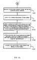
- FIGS. 4A and 4Billustrate a flowchart demonstrating a method of transmitting a signal for controlling an animal according to one embodiment of the invention.
- FIG. 5illustrates a flowchart demonstrating a method of receiving a signal for use in controlling an animal according to one embodiment of the invention.
- FIG. 6illustrates a flowchart demonstrating a method of transmitting a low power signal for use in controlling an animal according to one embodiment of the invention.
- FIGS. 7A and 7Billustrate a flowchart demonstrating a method of receiving a signal for use in controlling an animal, according to one embodiment of the invention.
- FIG. 8illustrates a method of modulating a signal so as to produce a train of signals, according to one embodiment of the invention.
- FIG. 9illustrates a transmitting and receiving system for controlling an animal, according to one embodiment of the invention.
- FIGS. 10A and 10Billustrate a flowchart demonstrating a method of combining more than one transmitters to create a zone for controlling a pet, according to one embodiment of the invention.
- FIGS. 11A and 11Billustrate a flowchart demonstrating a method of altering the initiation of a transmission within a window of time, according to one embodiment of the invention.
- FIGS. 12A and 12Billustrate a flowchart demonstrating a method of receiving a signal occurring at different initiation points within windows of time, according to one embodiment of the invention.
- FIG. 13illustrates a repeated signal shown as occurring at different initiation points within repeated windows of time, according to one embodiment of the invention.
- FIG. 14illustrates a transmitting and receiving system for controlling an animal, according to one embodiment of the invention.
- FIG. 15illustrates a flowchart demonstrating a method of utilizing multiple animal identifiers, according to one embodiment of the invention.
- FIG. 16illustrates a flowchart demonstrating a method of receiving an animal control signal identifying one of many correction signals for application to the animal, according to one embodiment of the invention.
- FIG. 17illustrates a system for transmitting and receiving animal control signals, according to one embodiment of the invention.
- FIGS. 18A and 18Billustrate a flowchart demonstrating a method of applying a correction signal to an animal, according to one embodiment of the invention.
- FIG. 19illustrates the block diagram of a system for applying a correction signal to an animal, according to one embodiment of the invention.
- FIG. 20illustrates a graph of a correction signal that can be applied to an animal according to one embodiment of the invention.
- FIG. 21illustrates how avoidance zones can be established around a transmitter, according to one embodiment of the invention.
- FIG. 1illustrates an exemplary layout of a home in which some of the embodiments of the invention can be used.
- FIG. 1shows transmitters 10 and 12 being placed at the ends of a long couch 16 .
- FIG. 1shows a transmitter 30 placed near a toilet 34 so as to discourage pets from drinking out of a toilet. Again, AC outlets are not typically conveniently located in bathrooms. Furthermore, running power cords in a bathroom can be dangerous due to the shock hazard.
- transmitter 40is placed near a front door in FIG. 1 to keep house pets from running out the door when opened or possibly for keeping dogs from jumping on visitors when they enter the home. Again, the front door area of a home is often one that does not have an AC outlet for providing a power source for the transmitter.
- a battery powered transmitteris necessary in these and other situations.
- Providing a battery powered transmitter that provides a signal that is of sufficient strength so that it can create a zone of protectionhas been difficult to achieve until now.
- AC unitsare capable of providing a strong signal with little worry about the power being used to transmit the signal
- battery powered unitsneed to be able to generate a signal of sufficient strength while at the same time allowing the signal to be transmitted for several months. This will keep the pet owner from having to change the batteries too frequently.
- a transmitter that could transmit a signal for 6, 5, 4, or 3 months without requiring replacement of the batterieswould be sufficient.
- FIG. 1shows that the transmitters can be used together to form a large avoidance zone.
- FIG. 1shows that transmitters 10 and 12 can be used together to form an avoidance zone that covers the entire couch 16 . This is beneficial in that it allows a large area to be covered with a transmitter/receiver system. While FIG. 1 shows that the avoidance zone is created by units placed at the ends of the couch, one could also place the units underneath the couch to shorten the avoidance zone.
- FIG. 1also shows that different animals can be kept away from different areas.
- the dashed line signals around transmitter 30 and 40are intended in this example to correct a dog that might drink from the toilet or run out through the open front door.
- the signal around couch 16is intended to correct a cat that might like to scratch or climb on the couch.
- FIG. 1illustrates that different animals can enter different avoidance zones that are not programmed to apply to them, while the other animals for which the avoidance zone was designed are kept away from the avoidance zones.
- the ability to keep pets out of certain areas of the homerequires that a battery powered unit be used in order to place a transmitter in an effective location.
- the unitneeds to be of sufficiently low power so that it can last for a dependably long enough time, e.g., around 3 to 6 months, so as not to be annoying to the consumer who has to replace the batteries.
- FIG. 2illustrates that a header signal is used to wake up a receiver.
- the header signalis shown as being 16 cycles of the carrier wave. This header is sensed by the receiver which detects the presence of energy.
- a buffer period of eight cyclesis shown in FIG. 2 to separate the header and payload of the data signal. The buffer period can be used to allow the receiver to initialize after being woken up by reception of the header signal.
- the transmitterthen transmits the payload signal which, according to this example, is comprised of 8 data segments. Each of the data segments is transmitted for 8 cycles so as to allow the receiver to determine the value of the data segment.
- the transmitteraccording to this example can transmit 8 data bits.
- a unique transmission schemecan be used to reduce the number of transmissions that draw current from the power source.
- the signals that draw current from the power sourceare the ones that reduce the life of the battery source. For example, a data signal for each data bit in FIG. 2 can be transmitted only when a binary data bit of the value “1” occurs. This allows the transmitter to conserve power by not transmitting a signal, where the lack of transmission during a specific time period indicates to a receiver a binary data bit of the value “0”.
- FIGS. 4 a and 4 bThis transmission scheme can be illustrated by flowchart 400 in FIGS. 4 a and 4 b .
- a digital messageis provided for communication to a receiver.
- An example of thisis the code “10100000” which can be associated with the message that a correction signal should be applied to a large dog wearing the animal collar programmed with that code.
- the digital messageis stored at the transmitter for transmission.
- a carrier wavesuch as a generally sinusoidal wave at 6.25 KHz is provided for use by a transmitter (block 440 ).
- the transmittercan then transmit the carrier wave in accordance with the digital message so as to transmit the carrier wave for each occurrence of a first digital signal (e.g., a digital “1”) and not to transmit the carrier wave for each occurrence of the opposing digital signal or second digital signal (e.g., a digital “0”).
- a first digital signale.g., a digital “1”
- second digital signale.g., a digital “0”
- a series of 8 cycles of the carrier wavewould be applied, followed by 8 cycles of no transmission of the carrier wave, followed by transmission of another 8 cycles of the carrier wave, followed by no transmission of the carrier wave for yet another 40 cycles.
- the receivercould then detect what digital message was being conveyed based on the occurrence or lack of occurrence of the carrier wave after the wake up signal.
- a battery operated unitcould be used to transmit this signal since it requires very little power.
- a transmitter unitis configured with both a battery power mode and an AC power mode, then the AC power mode could transmit in this fashion, as well. It is envisioned that this transmission scheme will be very beneficial when used as a battery powered transmission scheme, however.
- Block 470illustrates that the carrier wave signal is repeatedly transmitted according to the digital message. This allows the receiver assembly worn by the animal to trigger off of the received signal and apply the appropriate correction signal.
- the encoded carrier wave signalcan be sent repeatedly every 300 ms to convey the 8 bit message. If the animal wearing a collar assembly receiver is standing within an avoidance zone, it can be issued a correction signal every time the 8 bit signal is received.
- FIG. 5illustrates an exemplary animal collar assembly 300 .
- a carrier wave signalis received for use in controlling an animal. As explained above, this can involve receiving a series of cycles of a substantially sinusoidal waveform transmitted by the transmitter. The message communicated by the carrier wave signal can be used to control the animal.
- the digital messageis determined from the carrier wave signal, wherein reception of the carrier wave corresponds to a first digital signal in the digital message and non-reception of the carrier wave corresponds to a second digital signal in the digital message.
- the second digital signalis the opposite of the first digital signal. Therefore, if the first digital signal is a “1” then the second digital signal is a “0” and vice versa.
- the digital messagecan be used to decide whether to apply a correction signal as shown in block 550 , e.g., in the form of a sound or a stimulation signal.
- the digital messagecan be associated with a specific animal collar.
- Any animal collar that is programmed with that digital message and receives that digital messagewould know to apply a correction signal to the pet. Any animal collar not pre-programmed with that digital message and which received that digital message would conclude not to apply the correction signal.
- different petscould be controlled by different transmitters—thus keeping cats away from a sofa that they might scratch, while allowing dogs to sleep at the side of the sofa.
- the digital messagecould be indicative of a level of stimulation to apply.
- a digital signal sent by the transmitter at the trash cancould be equated with a weak correction signal while the digital message sent by the transmitter at the front door could be equated with a strong correction signal (since you would want to prevent the dogs from running out the front door and into the traffic).
- a table look up function in a processorcould be used to determine what correction signal to apply for each digital message received. Furthermore, a combination of these examples could be used.
- FIG. 8illustrates an example of the transmission scheme discussed above. Namely, in FIG. 8 a digital signal 800 is used to modulate a substantially sinusoidal carrier wave 804 . While a substantially sinusoidal carrier wave is used for exemplary purposes, other signals might be useful in some situations.
- the carrier waveis modulated according to the digital input to produce the sequence of carrier waves shown in graph 808 . These signals are transmitted to the receiver from the portable transmitter in FIG. 1 , for example. In this example, as compared to FIG. 2 , the carrier wave is only transmitted for 3 cycles when a digital “1” is encountered. Each occurrence of a digital “0” in the digital input produces a “silent” period of no transmission of the carrier wave 804 .
- a carrier waveis considered to be the signal that is transmitted from the transmitter to the receiver for use in communicating a message.
- transmission of a carrier wavewill be interrupted for purposes of conveying the message.
- the carrier wavewill have the same general shape as the input wave form.
- a pattern of signalshas a beginning signal and an ending signal.
- This on/off modulation schemeis beneficial from a power perspective in that it reduces the number of current drawing instances when communicating a digital message.
- the width of a transmissionindicates the value as being a “1” or a “0”.
- pulse width modulationdraws current regardless of whether a “1” or a “0” is transmitted.
- the on/off schemeavoids drawing current for at least one of the signals (i.e., either the 1's or the 0's).
- FIG. 8is an example in which no current is used to convey the 0's.
- this schemecan be utilized further by selecting a coding scheme for the digital message that reduces the number of times that the current drawing value occurs in the message (e.g., reducing the occurrence of “1's” to only twice in an 8 bit message so as to convey a predetermined message).
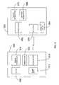
- FIG. 9illustrates a transmitter/receiver system that can be used for implementing the scheme described above.
- a transmitter system 900is configured to transmit a carrier wave signal, such as that shown in FIG. 8 to receiver system 950 .
- the transmitter 900is shown as having a memory 908 , a power supply 912 , a signal generator 924 , a modulator 920 , and a transmitter 916 .
- These elementscan be configured by independent circuits or in some instances with the use of a processor.
- the memoryfor example, could be configured from a series of switches to store the digital message transmitted by the transmitter system 900 . Alternatively, the memory could be configured from a processor that has local memory in which the digital message is stored.
- the signal generator 924can be used to generate a substantially sinusoidal signal for modulation by the digital message and transmission to the receiver system 950 .
- the signal generator and memoryare coupled with the modulator circuit 920 to allow the digital message to be used to modulate the signal generated by the signal generator.
- a processorcould be used to accomplish the modulation.
- the modulatorcould be a separate circuit or integral with the transmitter 916 .
- the transmittercan be coupled with the memory and the generator so as to transmit the carrier wave in accordance with each occurrence of the first digital signal and so as not to transmit the carrier wave in accordance with each occurrence of the second digital signal in the digital message.
- the power supplyis shown as block 912 .
- the power supply used for the on/off transmission scheme described abovecan be either battery powered or AC powered. However, it is envisioned that in many instances a battery powered system will provide a great deal of flexibility for the user in placing the transmitter in locations where no AC power is readily available.
- the receiver system 950is shown having a receiver 958 , a processor 962 , a wake up circuit 954 , a sound generator 970 and a stimulation generator 966 .
- the receiveris configured to receive the carrier wave signal sent by the transmitter. As explained above, the digital message embodied by that carrier wave can be used to determine how to control an animal such as one's pet dog or cat.
- the receiveris coupled with the processor 962 to translate or demodulate the carrier signal.
- the processoris configured to determine a digital message from the carrier wave signal wherein reception of the carrier wave corresponds to a first digital signal (e.g., a “1”) in the digital message and non-reception of the carrier wave corresponds to a second digital signal (e.g., a “0”) in the digital message.
- the first and second digital signalsare opposites of one another (e.g., “1” and “0” or “0” and “1”).
- FIG. 9shows alternative correction signal generators that can be used to generate the correction signal sent to the animal.
- a sound generator 970is shown for generating an audible sound within the hearing range of the animal.
- the voltage generator 966can also be used to generate a stimulation signal for the animal. Again, as shown in FIG.
- the receiver systemcan be part of a collar assembly 300 for coupling with the animal.
- a wake up circuit 954is also shown in FIG. 9 .
- the wake up circuitis a low power circuit that allows the receiver system to sense the presence of an energy signal, such as an RF signal.
- the wake up circuitcan be operated to sense the signal while the remaining circuit elements are run in low power or sleep mode. This allows the receiving system to be operated at low power until needed.
- Upon sensing a signal, such as the header signal shown in FIG. 2the remaining circuit elements in receiver system 950 can be invoked as needed.
- a highly beneficial transmitteris one that can provide a sufficiently powerful signal so as to be received by the receiver while at the same time enduring for a long period of time without requiring a change of batteries, such as for 3, 4, 5, or 6 months.
- Thisallows the transmitter to be portable so that it can be used in locations that do not have AC power readily available. It also allows for the transmitter to be operated for substantially long periods of time without the pet owner having to change the batteries.
- a method of implementing such a low power transmittercan be seen in flowchart 600 in FIG. 6 .
- a transmitteris provided in block 610 and power is provided for the transmitter in block 620 .
- a message for communicationis provided in block 630 for communication to a receiver, wherein the message is configured to implement a routine for application of a specific correction signal to the animal.
- the messageis transmitted at about 0.0167 Watts average power.
- the messagecould be transmitted at 0.00333 Watts average power.
- the messagecould be transmitted at 0.00167 Watts average power; thus, allowing the transmitter to be operated with 3 “AA” cell batteries.
- the messagecan be repeatedly transmitted to the receiver.
- the signaling format shown in FIG. 2can be used according to the transmission scheme described in FIGS. 4 a and 4 b .
- the transmitter system 900 in FIG. 9can be used to transmit the low power system signal.
- a payload signal sent according to the formatting of FIG. 2can be sent where the payload signal comprises only 2 digital “1” values and 6 digital “0” values. This allows 21 distinct messages to be sent with an 8 bit message.
- the transmittercan be configured to only transmit the carrier wave for occurrences of digital “1's” wherein each digital one causes the carrier wave to be transmitted for 8 cycles each of the carrier wave at 6.25 KHz.
- an average poweris measured to be only 0.00165 Watts or 370 microamps at 4.5 V. This is a significant improvement over the power needed by some AC powered pulse width modulated devices, such as the IFA-12 which at maximum output requires approximately 115 mA at 14.3 V which is 1.65 Watts. As can be seen, the average power for the AC unit is 1000 times that of this embodiment of the invention.
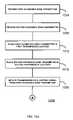
- a receivercan be used to detect the digital message sent by the transmitter in a unique fashion. This is illustrated, for example, by flowchart 700 in FIGS. 7 a and 7 b .
- a receiveris configured to receive a signal having a predetermined frequency. For example, for a carrier wave being transmitted at 6.25 KHz, the predetermined frequency would be 6.25 KHz.
- the receivercan be configured with a wake up detector circuit to sense the presence of an RF signal for example.
- the wake up signalcan be that shown in FIG. 2 for example—a series of cycles of the carrier wave for 16 cycles followed by 8 cycles of no transmission of the signal.
- the receivercan detect not only the presence of a signal but can also make a determination that the signal that is being received is of the predetermined frequency that the receiver is configured for. If the signal is detected to be of the predetermined frequency, then the receiving circuit elements can be initiated to receive the transmission packet message.
- Thiscan be implemented according to one embodiment of the invention by taking a first set of samples of the signal at multiple intervals during a first time period corresponding to at least one cycle at the predetermined frequency, as shown in block 730 . Then, this first set of samples can be used to calculate a characteristic of the signal for the first cycle, as shown in block 740 .
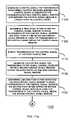
- a second set of samples of the signalcan be taken at multiple intervals during a subsequent time period corresponding to at least one cycle at the frequency, as shown in block 750 .
- the second set of samplesis utilized to calculate the characteristic of the signal during the second cycle, for example.
- the calculated characteristic of the first time periode.g., cycle #1
- the calculated characteristic of the subsequent time periode.g., cycle #2
- the digital message embodied in the transmission packetcan be determined from the signal, as shown in block 770 . Once the digital message is determined, it can be used to trigger application of the correction signal that is transmitted to the animal, as shown in block 780 .
- one such characteristic that can be determinedis the Peak_Sig according to the formula shown above.
- the Peak_Sigcan then be computed for each of the 8 cycles per bit, as shown for FIG. 2 .
- thisallows a processor to compare the Peak_Sig value for each cycle. However, one could even choose to skip a cycle, rather than calculating Peak_Sig for every cycle. If the Peak_Sig values for the 8 cycles match, then they confirm that the signal is being transmitted at the predetermined frequency—i.e., at 6.25 KHz according to this example.
- the transmitter/receiver schemeutilizes the coding system that only two of the 8 bits will be a digital “1” and only “1's” will cause a carrier wave to be transmitted, then the receiver can determine that the received signal corresponds to a digital “1”. Similarly, the Peak_Sig can be applied to the time interval associated with the second most significant bit in FIG. 2 . If no signal is received during this time interval, then the receiver will associate the lack of reception of a signal with a digital “0” under this example. It should be noted that the transmission scheme could be reversed so that the receiver recognized “no-reception of the carrier wave” as a “1” instead of a “0” and “reception of the carrier wave” as a “0” instead of a “1”.
- the receiver shown in FIG. 9could again be used.
- the receivercould be configured to receive the signal having the predetermined frequency, such as 6.25 KHz.
- the processor 962could be configured to take the first set of samples with the receiver at multiple intervals during the first time period corresponding to at least one cycle at the frequency.
- the processorcould be configured to calculate the characteristic for the samples, such as by calculating the Peak_Sig value described above. The processor could then repeat this process for a subsequent cycle.
- the processorcould be configured to compare the characteristics for the two cycles to see if they are equivalent and indicative that the transmission is at the predetermined frequency.
- the processorcan be configured to determine from the received transmission packet the digital message.
- the processorcan determine whether to transmit a correction signal to the animal.
- One way to implement thiswould be to store a digital message in the processor, thus designating that receiver as one that would initiate a correction signal every time the digital message is received. Then, the processor could merely compare the received digital message with the value stored at the processor. If they match, the correction signal can be applied. If they don't match, then the receiver would not apply a correction signal.
- the coding scheme used in the example aboveis beneficial because it reduces the need for power, as well. Namely, the coding scheme provides that for every eight bit packet, only 2 of the bits will be 1's. Thus, 21 codes can be communicated to the receiver by only transmitting for 2 data bits during the payload portion of the signal. As can be appreciated by one of ordinary skill in the art, additional messages beyond the 21 could be provided by lengthening the payload to a number greater than 8 bits, e.g., 16 bits where only two of the bits are “1”.
- one embodimentallows for multiple transmitters to be used in conjunction with one another. This can be accomplished by the method illustrated by flowchart 1000 in FIGS. 10 a and 10 b .
- the transmittercan be placed in their respective locations within a house, for example, as illustrated by blocks 1012 and 1016 .
- a transmission of a control signalcan be initiated from the first transmitter as shown in block 1020 as well as from the second transmitter. To keep the two transmitters from interfering with one another, the transmission of their signals can be varied.
- the initiation of successive transmissions of the control signal from the first transmittercan be varied within its transmission windows or control signal windows.
- the initiation of the transmission packets sent by the second transmittercan be varied as well within its transmission windows, as shown by block 1028 .
- FIG. 1illustrates that two transmitters can be placed at the opposite ends of a couch to establish a large avoidance zone for the couch—for example to keep a cat off of the couch when the owner is out of the room.
- the two transmitterscan be configured to transmit at varying intervals so that there is less likelihood that the signals from one another would interfere with each other.
- the system described abovecan be used to effectively protect a large area.
- FIGS. 11 a and 11 bfurther illustrate the method of varying the time in a sequence of transmission windows.
- FIG. 13 and FIG. 2help to illustrate the method of flowchart 1100 , as well.
- FIG. 2illustrates a wake up signal and data packet that are sent as a transmission packet to a receiver. This transmission packet corresponds to the hatched area within the transmission windows “T” shown in FIG. 13 .
- the period of the carrier signalis 160 microseconds per cycle.
- To transmit a transmission packet according the exemplary scheme shown in FIG. 2would take 88 cycles at 160 microseconds per cycle. Thus, this is equal to 14.08 milliseconds to transmit the entire transmission packet.
- a transmittercan transmit the transmission packet within successive windows (e.g., transmission windows “T” in FIG. 13 ) at 300 milliseconds and be very effective. Of course, other time periods could be used as well. Thus, when 300 millisecond windows are used, there is quite a bit of room for varying when to start transmission of the 14.08 millisecond transmission packet.
- FIG. 13shows the initiation point varying from window to window from points “A” to “B” to “C” and back to “A” again.
- a randomization circuitsuch as a processor configured to generate a random number or a separate circuit to generate a randomization factor, and then choose the initiation point (i.e., “A”, “B”, “C”, etc.) within each window.
- FIGS. 11 a and 11 billustrate a transmission scheme according to flowchart 1100 .
- a control signalis generated for transmission to an animal control receiver, wherein the control signal is generated for transmission within a control signal window and wherein the control signal window is longer than the control signal.
- a first point within the control signal windowis determined from which to begin transmission of the control signal. The first point is selected so as to still allow for transmission of the control signal packet within the control signal window.
- transmission of the control signal at the initiation pointis initiated.
- the control signalis generated for transmission to the animal control receiver within a second control signal window having the same period as the first control signal window.
- a second point in time or initiation pointis determined for the second control signal window from which to begin transmission of the control signal, as shown in block 1120 .
- the second initiation pointallows for the transmission of the control signal packet within the second control signal window.
- the transmission of the control signalcan be initiated again starting at the second initiation point, as shown in block 1124 .
- this processcan be repeated by transmitting the control signal packet in successive control signal windows of the same period while varying the initiation of transmission of the control signal packet within successive control signal windows.
- a randomization circuitto select successive initiation points.
- a processormight choose to randomize the initiation point for 4 out of 5 transmission windows—but, initiate the transmission for the fifth window at the beginning of the fifth transmission window.
- a receiver that receives this “jittered” type of signalcan be configured to check for the variation.
- the flowchart 1200 shown in FIGS. 12 a and 12 billustrate one such method.
- a first control signalis received from an animal control transmitter.
- a routineis initiated for controlling at least one correction signal to the animal in response to receiving the first control signal from the animal control transmitter, as shown in block 1208 .
- a control signal windowcan be established for receipt of a second control signal from the animal control transmitter in block 1212 .
- a checkcan be made for a second control signal within the second control signal window so as to allow the second control signal to be transmitted at a different initiation point in the second control signal window than was used for the initiation point for the control signal in the first control signal window, as shown in block 1216 .
- the receivercan terminate the correction signal routine if the second control signal is not received within the second control signal window, as shown by block 1220 . However, if the second control signal is received within the second control signal window, as shown by block 1224 , then the routine for applying the correction signal can continue.
- block 1228illustrates that the correction signal is applied to the animal.
- a series of correction signalscan be applied to the animal for every correction signal window in which the control signal packet is received.
- the initial magnitude of the correction signal that is applied to the animalcan be determined in one example by determining the strength of the received signal.
- the strength of the signalcan be used to indicate the relative location of the animal within the avoidance zone, i.e., a strong signal indicates the animal is closer to the transmitter than would a weak signal.
- each subsequent correction signal that is applied to the animal during its time inside the avoidance zoneis applied with a greater intensity relative to the previous correction signal—up to a predetermined maximum intensity. After a predetermined time at the maximum intensity, the unit would shut down.
- block 1236illustrates that after a period of time in which the animal is not removed from the zone, the time intervals between correction signals could be randomized.
- a collar assemblycan be used to hold the receiver and apply the correction signal in the form of a sound or an electrical stimulation, as shown in block 1240 .
- FIG. 14shows a transmitter/receiver system to implement the method of FIGS. 13 a and 13 b , according to one embodiment of the invention.
- FIG. 14illustrates a system 1400 of transmission system 1410 and receiving system 1450 .
- the transmission system in this exampleis shown as having a memory 1414 for storing a control signal for transmission to an animal control receiver.
- the memorycould take a variety of forms. It could be a memory chip programmed with the information. Alternatively, it could be as simple as a series of switches such as BCD switches configured to store an 8 bit message, for example. This would allow the transmission system to be configured to a particular message depending on how the pet owner wanted to use the transmitter—for example, for a cat, a little dog, a big dog, etc.
- FIG. 14also shows a transmission initiation circuit for varying the initiation point for transmitting a control signal within a control signal window.
- the processor 1418can be configured to select and vary the initiation points within successive windows.
- the processorcan be configured with a randomization feature.
- FIG. 14also shows a transmitter 1420 coupled with the memory and coupled with the processor. The transmitter can be configured to transmit the control signal stored by the memory as part of a transmission packet within successive control signal windows at varying points of initiation within successive control signal windows.
- the processorcan be further configured to vary the initiation point by either randomizing the initiation point or applying a predetermined sequence of initiation points.
- the receiving systemis shown in FIG. 14 as system 1450 . It is shown as having a receiver 1466 for receiving the signal from the transmitter. It too is shown having a processor 1454 . Furthermore, the example in FIG. 14 is shown with a voltage generator or supply 1458 and a sound generator 1462 .
- the processoris configured for initiating a routine for controlling at least one correction signal for application to the animal in response to receiving the first control signal from the animal control receiver. For example, this routine could simply be the application of the correction signal every time that the control signal packet is received from the transmitter.
- the processoris configured for establishing a control signal window for receipt of a second control signal from the animal control transmitter while at the same time allowing the second control signal to be transmitted at a different initiation point within the second control signal window as opposed to the initiation point that was used for the first control signal window.
- the processor and receiving systemcan be further configured to implement the routines described in FIGS. 12 a and 12 b , for example.
- each 8 bit signal sent in the exemplary signal of FIG. 2can be associated with a unique pet.
- a digital value of “10100000”can be associated with correcting the pet wearing the animal collar programmed to that code—such as the family cat.
- the digital value of “10010000”can be associated with correcting the pet wearing the animal collar programmed to that code—such as the family dog.
- Table 1shows an example of 21 different codes that can be implemented with an 8 bit code when only two of the bits are allowed to be 1 and the two 1's must be separated by a 0. This is a useful coding system for low power transmissions as explained above.
- code “0”could be used to control the family cat for which a tone is generated to keep the cat away from avoidance zone 1.
- code “1”could be used to control a small dog for which the correction signal is an appropriate electrical stimulation signal to encourage the dog to stay out of avoidance zone 2.
- code “3” in Table 1could be used to control a large dog for which the correction signal is used to encourage the large dog to stay out of avoidance zone 3.
- FIG. 15illustrates a flowchart 1500 for implementing a method of establishing different zones that can be used to control different pets.
- a transmitteris provided.
- multiple identifiersare stored with the transmitter wherein each of the identifiers is associated with a different animal.
- just one identifiercan be stored at the transmitter or a series of switches can be provided to allow the transmitter to be set to the appropriate code in Table 1, for example, as the user desires, as shown in block 1530 .
- the transmittercan then transmit the animal control signal which matches the selected identifier as shown in block 1540 .
- the systemis simple in that it does not require that a signal be received from the animal indicating that the animal is present within the zone.
- transmitting the signalis to transmit a header, such as a wake LIP signal, as shown in block 1550 and also transmit a payload which comprises the control signal, such as an 8 bit code having only two digital “1's”, as shown in block 1560 .
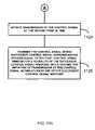
- the receiving methodcan be implemented according to the example shown in FIG. 16 and flowchart 1600 .
- a receiverreceives an animal control signal from a transmitter.
- the animal control signalis received without the receiver transmitting a signal to indicate to the transmitter the presence of the animal in an avoidance (or target) zone, as shown in block 1610 .
- the receivercan be configured to store an identifier in its memory, as shown in block 1620 .
- the identifieris used to identify the animal as one of many animals in a household, for example.
- a processoris provided to and configured to initiate a routine for application of the correction signal to the animal if the animal control signal received from the transmitter matches the identifier, as shown in block 1630 .
- a correction signalcan be generated for use by the correction routine, in block 1640 .
- FIG. 17illustrates a system for implementing the method described in FIGS. 15 and 16 .
- FIG. 17shows system 1700 having a transmission system 1710 .
- the exampleshows a processor 1720 coupled with memory 1730 and transmitter circuit 1740 .
- the memorycan be a memory chip or a series of switches capable of being configured to store a message.
- the processorcan be configured to implement the transmission method illustrated in FIG. 15 .
- the receiver system 1750is shown as having receiver 1760 and memory 1770 as well as processor 1780 and correction signal generators 1790 and 1795 .
- the memorycan take a form similar to that described for the transmitter.
- the processorcan essentially be configured to implement the method described in FIG. 16 .
- an animalmight acclimate to regular, periodic stimulation when the animal enters an avoidance zone.
- regular, periodic stimulationwhen the animal enters an avoidance zone.
- the random stimulationcan be more annoying to the animal than the regular, periodic stimulation, thus encouraging the animal to vacate the zone.
- FIG. 20illustrates an example of the randomization principle.
- a series of control signalsare transmitted and received by the receiver. Over a period of time the receiver increases the stimulation LIP to a predetermined maximum. This is shown by the ramping up and leveling off of the signal in FIG. 20 .
- the collar assembly worn by the animalcan randomize the correction signal.
- FIG. 20shows a variety of ways in which the randomization can be implemented. For example, it can be implemented as different time intervals between correction signals, differing magnitudes of the correction signal, and different lengths of the correction signal. Of course, at time “t2” the receiver will cease any stimulation in case the animal is caught in the avoidance zone.
- FIG. 21illustrates that the magnitude of the initial correction signal can vary depending on the strength of the received signal at the receiver.
- FIG. 21shows an avoidance zone covering areas A and B.
- the area Cis outside the avoidance zone. If the animal enters the avoidance zone quickly so as to end up in area A before a correction signal can be sent, the receiver can use a higher magnitude correction signal. On the other hand, if the animal is just inside area B, the signal received by the receiver will be of lower strength. The receiver can recognize this fact and use a correction signal of lower magnitude.
- FIGS. 18 a and 18 billustrate an example of a method of randomizing correction signals with a receiver assembly.
- a transmitted signalis detected with a detector indicating that the detector is located within a first zone, such as an avoidance zone.
- a first sequence of correction signalsis applied for controlling an animal in block 1808 .
- a determinationis made as to whether the animal has been stimulated but not moved from the zone, in block 1812 .
- a time periodcan be measured from when the first stimulation in the sequence of stimulation signals was applied to the animal.
- the receiver assemblycan wait a period of time after the application of the first sequence of control signals.
- a second sequence of correction signalscan be applied to the animal, as shown in block 1820 .
- the second sequencewill be different from the first sequence so as to encourage the animal to leave the avoidance zone in view of the fact that the animal has apparently become accustomed to the first sequence.
- block 1824shows that the receiver system can randomly select the time intervals between correction signals in the second sequence of correction signals.
- the receivercould also be configured to randomly select a signal magnitude for the correction signal in the second sequence of correction signals, as shown by block 1828 .
- FIG. 19illustrates a system for generating a random pattern of stimulation signals.
- a receiver assembly 1900such as an animal collar assembly having a collar for coupling the receiver with the animal and a transducer for transmitting a signal to the animal.
- a transmitted signal from a transmitteris shown as signal 1902 .
- the presence of the signalcan be detected and received by detector 1904 and processed by processor 1908 .
- the processorcan then cause application of the correction signal through the use of the correction signal generator 1912 .
- random generator 1916can be used to randomize the correction signal as explained above.
- the correction signalcan be applied with speaker 1914 or electrical stimulation 1920 .
- embodiments of the inventioncould be accomplished as computer signals embodied in a carrier wave, as well as signals (e.g., electrical and optical) propagated through a transmission medium.
- signalse.g., electrical and optical
- the various information discussed abovecould be formatted in a structure, such as a data structure, and transmitted as an electrical signal through a transmission medium or stored on a computer readable medium.
Landscapes
- Life Sciences & Earth Sciences (AREA)
- Environmental Sciences (AREA)
- Health & Medical Sciences (AREA)
- General Health & Medical Sciences (AREA)
- Physical Education & Sports Medicine (AREA)
- Animal Behavior & Ethology (AREA)
- Zoology (AREA)
- Animal Husbandry (AREA)
- Biodiversity & Conservation Biology (AREA)
- Housing For Livestock And Birds (AREA)
Abstract
Description
Peak_Sig=(a0°−a180°)2+(a90°−a270°)2wherein “a” is the value of the signal at each expected phase position.
By sampling the signal at every 90 degree location for an expected frequency, two successive cycles of the received waveform should have the same Peak_Sig value. If the Peak_Sig values for the successive cycles do not have the same value, then one can determine that the signal being received is not being transmitted at the predetermined frequency.
| TABLE 1 | ||
| Code | ||
| Number | 7 | 6 | 5 | 4 | 3 | 2 | 1 | 0 |
| 0 | 1 | 0 | 1 | 0 | 0 | 0 | 0 | 0 |
| 1 | 1 | 0 | 0 | 1 | 0 | 0 | 0 | 0 |
| 2 | 1 | 0 | 0 | 0 | 1 | 0 | 0 | 0 |
| 3 | 1 | 0 | 0 | 0 | 0 | 1 | 0 | 0 |
| 4 | 1 | 0 | 0 | 0 | 0 | 0 | 1 | 0 |
| 5 | 1 | 0 | 0 | 0 | 0 | 0 | 0 | 1 |
| 6 | 0 | 1 | 0 | 1 | 0 | 0 | 0 | 0 |
| 7 | 0 | 1 | 0 | 0 | 1 | 0 | 0 | 0 |
| 8 | 0 | 1 | 0 | 0 | 0 | 1 | 0 | 0 |
| 9 | 0 | 1 | 0 | 0 | 0 | 0 | 1 | 0 |
| 10 | 0 | 1 | 0 | 0 | 0 | 0 | 0 | 1 |
| 11 | 0 | 0 | 1 | 0 | 1 | 0 | 0 | 0 |
| 12 | 0 | 0 | 1 | 0 | 0 | 1 | 0 | 0 |
| 13 | 0 | 0 | 1 | 0 | 0 | 0 | 1 | 0 |
| 14 | 0 | 0 | 1 | 0 | 0 | 0 | 0 | 1 |
| 15 | 0 | 0 | 0 | 1 | 0 | 1 | 0 | 0 |
| 16 | 0 | 0 | 0 | 1 | 0 | 0 | 1 | 0 |
| 17 | 0 | 0 | 0 | 1 | 0 | 0 | 0 | 1 |
| 18 | 0 | 0 | 0 | 0 | 1 | 0 | 1 | 0 |
| 19 | 0 | 0 | 0 | 0 | 1 | 0 | 0 | 1 |
| 20 | 0 | 0 | 0 | 0 | 0 | 1 | 0 | 1 |
Claims (49)
Peak_Sig=(a0°−a180°)2+(a90°−a270°)2wherein “a” is the amplitude of said signal.
Peak_Sig=(a0°−a180°)2+(a90°−a270°)2wherein “a” is the amplitude of said signal.
Priority Applications (1)
| Application Number | Priority Date | Filing Date | Title |
|---|---|---|---|
| US10/829,916US7046152B1 (en) | 2003-12-10 | 2004-04-21 | Method and apparatus for communicating control signals |
Applications Claiming Priority (2)
| Application Number | Priority Date | Filing Date | Title |
|---|---|---|---|
| US52862903P | 2003-12-10 | 2003-12-10 | |
| US10/829,916US7046152B1 (en) | 2003-12-10 | 2004-04-21 | Method and apparatus for communicating control signals |
Publications (1)
| Publication Number | Publication Date |
|---|---|
| US7046152B1true US7046152B1 (en) | 2006-05-16 |
Family
ID=36318134
Family Applications (1)
| Application Number | Title | Priority Date | Filing Date |
|---|---|---|---|
| US10/829,916Expired - LifetimeUS7046152B1 (en) | 2003-12-10 | 2004-04-21 | Method and apparatus for communicating control signals |
Country Status (1)
| Country | Link |
|---|---|
| US (1) | US7046152B1 (en) |
Cited By (36)
| Publication number | Priority date | Publication date | Assignee | Title |
|---|---|---|---|---|
| US7117822B1 (en)* | 2003-12-10 | 2006-10-10 | Innotek, Inc. | Method and apparatus for communicating a randomized signal |
| US20070109135A1 (en)* | 2005-11-03 | 2007-05-17 | Dogwatch Inc. | Transmitter loop monitor |
| US20090071413A1 (en)* | 2007-09-14 | 2009-03-19 | Dogwatch Inc. | Animal control system having correction monitor |
| USD632853S1 (en) | 2010-08-04 | 2011-02-15 | Titan Pet Products, Inc. | Electronic pet tag |
| US20110061605A1 (en)* | 2009-09-12 | 2011-03-17 | Titan Pet Products, Inc. | Systems and methods for animal containment, training, and tracking |
| US20110234410A1 (en)* | 2010-03-25 | 2011-09-29 | Groh William S | Solar Powered Animal Containment/Repellent System |
| US8186310B1 (en) | 2010-07-22 | 2012-05-29 | Smith Theodore L | Collar system for protection of cats from dogs |
| USD665952S1 (en)* | 2012-01-16 | 2012-08-21 | Guo xu wei | Receiver |
| USD673334S1 (en)* | 2012-01-16 | 2012-12-25 | Guo xu wei | Receiver |
| US20150156016A1 (en)* | 2013-12-03 | 2015-06-04 | Radio Systems Corporation | Method and apparatus for verifying battery authenticity |
| US9293027B2 (en) | 2011-12-28 | 2016-03-22 | Jason Wilson | System for repelling a pet from a predetermined area |
| US9578856B2 (en) | 2013-11-12 | 2017-02-28 | E-Collar Technologies, Inc. | System and method for preventing animals from approaching certain areas using image recognition |
| US10986816B2 (en) | 2014-03-26 | 2021-04-27 | Scr Engineers Ltd. | Livestock location system |
| US10986817B2 (en) | 2014-09-05 | 2021-04-27 | Intervet Inc. | Method and system for tracking health in animal populations |
| US11071279B2 (en) | 2014-09-05 | 2021-07-27 | Intervet Inc. | Method and system for tracking health in animal populations |
| US11172649B2 (en) | 2016-09-28 | 2021-11-16 | Scr Engineers Ltd. | Holder for a smart monitoring tag for cows |
| US11246292B2 (en) | 2019-05-30 | 2022-02-15 | Infinity Collar Llc | System for providing a dynamic portable virtual boundary |
| USD990062S1 (en) | 2020-06-18 | 2023-06-20 | S.C.R. (Engineers) Limited | Animal ear tag |
| USD990063S1 (en) | 2020-06-18 | 2023-06-20 | S.C.R. (Engineers) Limited | Animal ear tag |
| US11832584B2 (en) | 2018-04-22 | 2023-12-05 | Vence, Corp. | Livestock management system and method |
| US11832587B2 (en) | 2020-06-18 | 2023-12-05 | S.C.R. (Engineers) Limited | Animal tag |
| US11864529B2 (en) | 2018-10-10 | 2024-01-09 | S.C.R. (Engineers) Limited | Livestock dry off method and device |
| US11960957B2 (en) | 2020-11-25 | 2024-04-16 | Identigen Limited | System and method for tracing members of an animal population |
| US12099893B2 (en) | 2020-07-01 | 2024-09-24 | S.C.R. (Engineers) Limited | Device assignment system and method |
| US12102059B2 (en) | 2018-03-14 | 2024-10-01 | Protect Animals with Satellites, LLC | Corrective collar utilizing geolocation technology |
| US12144320B2 (en) | 2019-02-08 | 2024-11-19 | Allflex Australia Pty Ltd | Electronic animal identification tag reader synchronisation |
| US12156510B2 (en) | 2021-03-08 | 2024-12-03 | Protect Animals with Satellites, LLC | Corrective collar utilizing geolocation technology |
| US12193413B2 (en) | 2019-02-08 | 2025-01-14 | Allflex Australia Pty Ltd | Electronic animal tag reader |
| US12213449B2 (en) | 2021-01-24 | 2025-02-04 | S.C.R. (Engineers) Limited | Animal marking control system and method |
| US12219933B1 (en) | 2020-09-24 | 2025-02-11 | Protect Animals with Satellites, LLC | System and method for tracking an animal and for preventing the animal from attacking another animal |
| US12239098B2 (en) | 2019-02-08 | 2025-03-04 | Allflex Australia Pty Ltd | Determining the location of an animal |
| USD1067554S1 (en) | 2021-04-08 | 2025-03-18 | Allflex Australia Pty Limited | Tag applicator for animals |
| USD1067544S1 (en) | 2021-04-08 | 2025-03-18 | Allflex Australia Pty Limited | Tag applicator for animals |
| US12402596B2 (en) | 2022-05-03 | 2025-09-02 | S.C.R. (Engineers) Limited | Milk channel and feed inlet coupled thereto, and system and method for conserving wash fluid in a washing process for cleaning a milkmeter system |
| US12402599B2 (en) | 2018-10-03 | 2025-09-02 | Allflex Europe Sas | Gripper for manipulating a device for identifying an animal and/or removing tissue from an animal comprising holding means with remote actuation |
| US12409474B2 (en) | 2019-08-28 | 2025-09-09 | S.C.R. (Engineers) Limited | Devices for analysis of a fluid |
Citations (54)
| Publication number | Priority date | Publication date | Assignee | Title |
|---|---|---|---|---|
| US3589337A (en)* | 1969-10-06 | 1971-06-29 | Thomas H Doss | Radio controlled animal training device |
| US4898120A (en)* | 1988-06-16 | 1990-02-06 | Torrington Product Ventures, Inc. | Animal training and restraining system |
| US4967695A (en) | 1989-06-23 | 1990-11-06 | Invisible Fence Company, Inc. | System for controlling the movement of an animal |
| US4996945A (en) | 1990-05-04 | 1991-03-05 | Invisible Fence Company, Inc. | Electronic animal control system with lightning arrester |
| USD330173S (en) | 1991-03-11 | 1992-10-13 | Invisible Fence Company, Inc. | Combined signalling receiver and buckle and clamp unit for a dog collar |
| USD330685S (en) | 1991-02-01 | 1992-11-03 | Invisible Fence Company, Inc. | Signal transmitter |
| US5161485A (en) | 1991-12-31 | 1992-11-10 | Invisible Fence Company, Inc. | Animal collar arrangement |
| US5207178A (en) | 1992-01-31 | 1993-05-04 | Invisible Fence Company, Inc. | Electrode device for an electric shock generator carried on an animal collar |
| USD336055S (en) | 1991-12-31 | 1993-06-01 | Invisible Fence Company, Inc. | Combined signal receiver and buckle and clamp unit for an animal collar |
| US5353744A (en) | 1991-05-14 | 1994-10-11 | Dogwatch, Inc. | Animal control apparatus |
| US5381129A (en) | 1994-03-23 | 1995-01-10 | Radio Systems, Inc. | Wireless pet containment system |
| US5408956A (en) | 1993-06-21 | 1995-04-25 | The United States Of America As Represented By The Secretary Of Agriculture | Method and apparatus for controlling animals with electronic fencing |
| US5425330A (en) | 1993-08-19 | 1995-06-20 | Invisible Fence Company, Inc. | Animal control device |
| US5435271A (en) | 1993-08-19 | 1995-07-25 | Invisible Fence Company, Inc. | Multi-channel animal control device with external data communication |
| US5445900A (en) | 1993-08-18 | 1995-08-29 | Invisible Fence Company, Inc. | Electronic device having a removable battery pack assembly |
| US5476729A (en) | 1993-08-18 | 1995-12-19 | Invisible Fence Company, Inc. | Electronic device having a removable battery pack assembly |
| US5533469A (en) | 1993-08-18 | 1996-07-09 | Invisible Fence Company, Inc. | Programming apparatus for programmable animal control device |
| US5559498A (en) | 1994-12-30 | 1996-09-24 | Innotek Inc. | Combination confinement and remote training system |
| US5576694A (en) | 1995-05-24 | 1996-11-19 | Invisible Fence Company, Inc. | Electronic animal control system with masking signal generator |
| US5606936A (en)* | 1995-04-25 | 1997-03-04 | Davis; James E. | Animal restraining system |
| US5636597A (en) | 1995-02-28 | 1997-06-10 | Innotek Pet Products, Inc. | Animal separator system |
| US5642690A (en) | 1986-01-21 | 1997-07-01 | Industrial Automation Technologies, Inc. | Animal containment system |
| US5787841A (en) | 1996-10-29 | 1998-08-04 | Joint Techno Concepts International, Inc. | Apparatus and method for electronic exclusion and confinement of animals relative to a selected area |
| US5799618A (en) | 1996-08-12 | 1998-09-01 | Innotek, Inc. | Combination confinement system and bark inhibitor |
| US5808551A (en)* | 1994-08-05 | 1998-09-15 | Yarnall, Jr.; Robert G. | Electronic confinement system for animals or people transmitting digitally encoded signals |
| US5870973A (en) | 1996-05-30 | 1999-02-16 | Invisible Fence Company, Inc. | Electronic animal control system transmitter with variable phase control |
| US5886672A (en) | 1997-01-29 | 1999-03-23 | Innotek Pet Products, Inc. | Collapsible antenna |
| US5911198A (en) | 1996-08-05 | 1999-06-15 | Innotek Pet Products, Inc. | Animal stimulator |
| US5913284A (en) | 1996-02-27 | 1999-06-22 | Innotek, Inc. | Stimulation device and technique |
| US5923254A (en) | 1997-01-29 | 1999-07-13 | Innotek Pet Products, Inc. | Programmable animal collar |
| US5987379A (en) | 1997-10-30 | 1999-11-16 | Trimble Navigation Limited | Creation and monitoring of variable buffer zones |
| US6043748A (en) | 1997-12-19 | 2000-03-28 | Invisible Fence Company, Inc. | Satellite relay collar and programmable electronic boundary system for the containment of animals |
| US6075443A (en)* | 1998-07-31 | 2000-06-13 | Sarnoff Corporation | Wireless tether |
| US6114957A (en) | 1998-02-19 | 2000-09-05 | Innotek Pet Products, Inc. | Pet locator system |
| US6155208A (en) | 1997-09-22 | 2000-12-05 | Agritech Electronics, Lc | Electronic animal control apparatus |
| US6163261A (en) | 1999-06-01 | 2000-12-19 | Innotek Pet Products, Inc. | Wireless pet confinement system |
| US6166643A (en) | 1997-10-23 | 2000-12-26 | Janning; Joseph J. | Method and apparatus for controlling the whereabouts of an animal |
| US6184790B1 (en) | 1999-01-29 | 2001-02-06 | Innotek, Inc. | Animal shock collar with low impedance transformer |
| US6232880B1 (en) | 1999-07-14 | 2001-05-15 | The United States Of America As Represented By The Secretary Of Agriculture | Animal control system using global positioning and instrumental animal conditioning |
| US6271757B1 (en) | 1997-12-19 | 2001-08-07 | Invisible Fence, Inc. | Satellite animal containment system with programmable Boundaries |
| US6327999B1 (en) | 1999-12-10 | 2001-12-11 | Innotek, Inc. | Electroshock stimulus monitoring method and apparatus |
| US6360697B1 (en) | 1999-11-19 | 2002-03-26 | Innotek, Inc. | Pressure pulse probe for animal behavior correction |
| US20020036569A1 (en)* | 2000-08-14 | 2002-03-28 | Martin Philip John | Tag and receiver systems |
| US6415742B1 (en) | 2000-07-03 | 2002-07-09 | Radio Systems Corporation | Dual transmitter pet confinement and training system |
| US6431122B1 (en) | 2000-11-21 | 2002-08-13 | Innotek, Inc. | Wireless confinement and training system for an animal |
| US6459378B2 (en) | 1999-01-29 | 2002-10-01 | Innotek, Inc. | Animal shock collar with low impedance transformer |
| US6487992B1 (en) | 1999-11-22 | 2002-12-03 | Robert L. Hollis | Dog behavior monitoring and training apparatus |
| US6581546B1 (en) | 2002-02-14 | 2003-06-24 | Waters Instruments, Inc. | Animal containment system having a dynamically changing perimeter |
| US6600422B2 (en) | 1996-10-29 | 2003-07-29 | Joint Techno Concepts International, Inc. | Apparatus and method for electronic exclusion and confinement of animals relative to a selected area |
| US6799537B1 (en) | 2004-01-06 | 2004-10-05 | Yi-Chia Liao | Pet training device |
| US6825768B2 (en) | 2001-06-14 | 2004-11-30 | Dogwatch, Inc. | Adaptive pet containment system and method |
| US6901883B2 (en) | 2003-08-19 | 2005-06-07 | Radio Systems Corporation | Multi-function animal training transmitter |
| US20050217606A1 (en) | 2004-04-02 | 2005-10-06 | Radio Systems Corporation | Intensity variation device for training animals |
| US6956483B2 (en) | 2002-06-28 | 2005-10-18 | Agri-Tech Electronics Lc | Animal control apparatus with ultrasonic link |
- 2004
- 2004-04-21USUS10/829,916patent/US7046152B1/ennot_activeExpired - Lifetime
Patent Citations (56)
| Publication number | Priority date | Publication date | Assignee | Title |
|---|---|---|---|---|
| US3589337A (en)* | 1969-10-06 | 1971-06-29 | Thomas H Doss | Radio controlled animal training device |
| US5642690A (en) | 1986-01-21 | 1997-07-01 | Industrial Automation Technologies, Inc. | Animal containment system |
| US4898120A (en)* | 1988-06-16 | 1990-02-06 | Torrington Product Ventures, Inc. | Animal training and restraining system |
| US4967695A (en) | 1989-06-23 | 1990-11-06 | Invisible Fence Company, Inc. | System for controlling the movement of an animal |
| US4996945A (en) | 1990-05-04 | 1991-03-05 | Invisible Fence Company, Inc. | Electronic animal control system with lightning arrester |
| USD330685S (en) | 1991-02-01 | 1992-11-03 | Invisible Fence Company, Inc. | Signal transmitter |
| USD330173S (en) | 1991-03-11 | 1992-10-13 | Invisible Fence Company, Inc. | Combined signalling receiver and buckle and clamp unit for a dog collar |
| US5353744A (en) | 1991-05-14 | 1994-10-11 | Dogwatch, Inc. | Animal control apparatus |
| USD336055S (en) | 1991-12-31 | 1993-06-01 | Invisible Fence Company, Inc. | Combined signal receiver and buckle and clamp unit for an animal collar |
| US5161485A (en) | 1991-12-31 | 1992-11-10 | Invisible Fence Company, Inc. | Animal collar arrangement |
| US5207178A (en) | 1992-01-31 | 1993-05-04 | Invisible Fence Company, Inc. | Electrode device for an electric shock generator carried on an animal collar |
| US5408956A (en) | 1993-06-21 | 1995-04-25 | The United States Of America As Represented By The Secretary Of Agriculture | Method and apparatus for controlling animals with electronic fencing |
| US5476729A (en) | 1993-08-18 | 1995-12-19 | Invisible Fence Company, Inc. | Electronic device having a removable battery pack assembly |
| US5533469A (en) | 1993-08-18 | 1996-07-09 | Invisible Fence Company, Inc. | Programming apparatus for programmable animal control device |
| US5445900A (en) | 1993-08-18 | 1995-08-29 | Invisible Fence Company, Inc. | Electronic device having a removable battery pack assembly |
| US5425330A (en) | 1993-08-19 | 1995-06-20 | Invisible Fence Company, Inc. | Animal control device |
| US5435271A (en) | 1993-08-19 | 1995-07-25 | Invisible Fence Company, Inc. | Multi-channel animal control device with external data communication |
| US5381129A (en) | 1994-03-23 | 1995-01-10 | Radio Systems, Inc. | Wireless pet containment system |
| US5808551A (en)* | 1994-08-05 | 1998-09-15 | Yarnall, Jr.; Robert G. | Electronic confinement system for animals or people transmitting digitally encoded signals |
| US5559498A (en) | 1994-12-30 | 1996-09-24 | Innotek Inc. | Combination confinement and remote training system |
| US5636597A (en) | 1995-02-28 | 1997-06-10 | Innotek Pet Products, Inc. | Animal separator system |
| US5606936A (en)* | 1995-04-25 | 1997-03-04 | Davis; James E. | Animal restraining system |
| US5576694A (en) | 1995-05-24 | 1996-11-19 | Invisible Fence Company, Inc. | Electronic animal control system with masking signal generator |
| US6073589A (en) | 1996-02-27 | 2000-06-13 | Innotek, Inc. | Stimulation device and technique |
| US5913284A (en) | 1996-02-27 | 1999-06-22 | Innotek, Inc. | Stimulation device and technique |
| US5870973A (en) | 1996-05-30 | 1999-02-16 | Invisible Fence Company, Inc. | Electronic animal control system transmitter with variable phase control |
| US5911198A (en) | 1996-08-05 | 1999-06-15 | Innotek Pet Products, Inc. | Animal stimulator |
| US5799618A (en) | 1996-08-12 | 1998-09-01 | Innotek, Inc. | Combination confinement system and bark inhibitor |
| US6058889A (en) | 1996-08-12 | 2000-05-09 | Innotek Pet Products, Inc. | Combination confinement system and bark inhibitor |
| US5787841A (en) | 1996-10-29 | 1998-08-04 | Joint Techno Concepts International, Inc. | Apparatus and method for electronic exclusion and confinement of animals relative to a selected area |
| US6600422B2 (en) | 1996-10-29 | 2003-07-29 | Joint Techno Concepts International, Inc. | Apparatus and method for electronic exclusion and confinement of animals relative to a selected area |
| US5923254A (en) | 1997-01-29 | 1999-07-13 | Innotek Pet Products, Inc. | Programmable animal collar |
| US5886672A (en) | 1997-01-29 | 1999-03-23 | Innotek Pet Products, Inc. | Collapsible antenna |
| US6155208A (en) | 1997-09-22 | 2000-12-05 | Agritech Electronics, Lc | Electronic animal control apparatus |
| US6166643A (en) | 1997-10-23 | 2000-12-26 | Janning; Joseph J. | Method and apparatus for controlling the whereabouts of an animal |
| US5987379A (en) | 1997-10-30 | 1999-11-16 | Trimble Navigation Limited | Creation and monitoring of variable buffer zones |
| US6271757B1 (en) | 1997-12-19 | 2001-08-07 | Invisible Fence, Inc. | Satellite animal containment system with programmable Boundaries |
| US6043748A (en) | 1997-12-19 | 2000-03-28 | Invisible Fence Company, Inc. | Satellite relay collar and programmable electronic boundary system for the containment of animals |
| US6114957A (en) | 1998-02-19 | 2000-09-05 | Innotek Pet Products, Inc. | Pet locator system |
| US6075443A (en)* | 1998-07-31 | 2000-06-13 | Sarnoff Corporation | Wireless tether |
| US6184790B1 (en) | 1999-01-29 | 2001-02-06 | Innotek, Inc. | Animal shock collar with low impedance transformer |
| US6459378B2 (en) | 1999-01-29 | 2002-10-01 | Innotek, Inc. | Animal shock collar with low impedance transformer |
| US6163261A (en) | 1999-06-01 | 2000-12-19 | Innotek Pet Products, Inc. | Wireless pet confinement system |
| US6232880B1 (en) | 1999-07-14 | 2001-05-15 | The United States Of America As Represented By The Secretary Of Agriculture | Animal control system using global positioning and instrumental animal conditioning |
| US6360697B1 (en) | 1999-11-19 | 2002-03-26 | Innotek, Inc. | Pressure pulse probe for animal behavior correction |
| US6487992B1 (en) | 1999-11-22 | 2002-12-03 | Robert L. Hollis | Dog behavior monitoring and training apparatus |
| US6327999B1 (en) | 1999-12-10 | 2001-12-11 | Innotek, Inc. | Electroshock stimulus monitoring method and apparatus |
| US6415742B1 (en) | 2000-07-03 | 2002-07-09 | Radio Systems Corporation | Dual transmitter pet confinement and training system |
| US20020036569A1 (en)* | 2000-08-14 | 2002-03-28 | Martin Philip John | Tag and receiver systems |
| US6431122B1 (en) | 2000-11-21 | 2002-08-13 | Innotek, Inc. | Wireless confinement and training system for an animal |
| US6825768B2 (en) | 2001-06-14 | 2004-11-30 | Dogwatch, Inc. | Adaptive pet containment system and method |
| US6581546B1 (en) | 2002-02-14 | 2003-06-24 | Waters Instruments, Inc. | Animal containment system having a dynamically changing perimeter |
| US6956483B2 (en) | 2002-06-28 | 2005-10-18 | Agri-Tech Electronics Lc | Animal control apparatus with ultrasonic link |
| US6901883B2 (en) | 2003-08-19 | 2005-06-07 | Radio Systems Corporation | Multi-function animal training transmitter |
| US6799537B1 (en) | 2004-01-06 | 2004-10-05 | Yi-Chia Liao | Pet training device |
| US20050217606A1 (en) | 2004-04-02 | 2005-10-06 | Radio Systems Corporation | Intensity variation device for training animals |
Cited By (48)
| Publication number | Priority date | Publication date | Assignee | Title |
|---|---|---|---|---|
| US7117822B1 (en)* | 2003-12-10 | 2006-10-10 | Innotek, Inc. | Method and apparatus for communicating a randomized signal |
| US7204204B1 (en) | 2003-12-10 | 2007-04-17 | Innotek, Inc. | Method for creating an avoidance zone |
| US7278376B1 (en) | 2003-12-10 | 2007-10-09 | Innotek, Inc. | Method of transmitting a signal for controlling an animal |
| US7495570B1 (en) | 2003-12-10 | 2009-02-24 | Innotek, Inc. | Transmitter apparatus |
| US20070109135A1 (en)* | 2005-11-03 | 2007-05-17 | Dogwatch Inc. | Transmitter loop monitor |
| US8006649B2 (en) | 2007-09-14 | 2011-08-30 | Dogwatch Inc. | Animal control system having correction monitor |
| US20090071413A1 (en)* | 2007-09-14 | 2009-03-19 | Dogwatch Inc. | Animal control system having correction monitor |
| US20110061605A1 (en)* | 2009-09-12 | 2011-03-17 | Titan Pet Products, Inc. | Systems and methods for animal containment, training, and tracking |
| US8438999B2 (en) | 2009-09-12 | 2013-05-14 | Titan Pet Products, Inc. | Systems and methods for animal containment, training, and tracking |
| US20110234410A1 (en)* | 2010-03-25 | 2011-09-29 | Groh William S | Solar Powered Animal Containment/Repellent System |
| US8186310B1 (en) | 2010-07-22 | 2012-05-29 | Smith Theodore L | Collar system for protection of cats from dogs |
| USD632853S1 (en) | 2010-08-04 | 2011-02-15 | Titan Pet Products, Inc. | Electronic pet tag |
| US9818286B2 (en) | 2011-12-28 | 2017-11-14 | Jason Wilson | System for repelling a pet from a predetermined area |
| US9293027B2 (en) | 2011-12-28 | 2016-03-22 | Jason Wilson | System for repelling a pet from a predetermined area |
| USD665952S1 (en)* | 2012-01-16 | 2012-08-21 | Guo xu wei | Receiver |
| USD673334S1 (en)* | 2012-01-16 | 2012-12-25 | Guo xu wei | Receiver |
| US9578856B2 (en) | 2013-11-12 | 2017-02-28 | E-Collar Technologies, Inc. | System and method for preventing animals from approaching certain areas using image recognition |
| US20150156016A1 (en)* | 2013-12-03 | 2015-06-04 | Radio Systems Corporation | Method and apparatus for verifying battery authenticity |
| US9703964B2 (en)* | 2013-12-03 | 2017-07-11 | Radio Systems Corporation | Method and apparatus for verifying battery authenticity |
| US10986816B2 (en) | 2014-03-26 | 2021-04-27 | Scr Engineers Ltd. | Livestock location system |
| US12213455B2 (en) | 2014-03-26 | 2025-02-04 | S.C.R. (Engineers) Limited | Livestock location system |
| US11963515B2 (en) | 2014-03-26 | 2024-04-23 | S.C.R. (Engineers) Limited | Livestock location system |
| US10986817B2 (en) | 2014-09-05 | 2021-04-27 | Intervet Inc. | Method and system for tracking health in animal populations |
| US11071279B2 (en) | 2014-09-05 | 2021-07-27 | Intervet Inc. | Method and system for tracking health in animal populations |
| US11172649B2 (en) | 2016-09-28 | 2021-11-16 | Scr Engineers Ltd. | Holder for a smart monitoring tag for cows |
| US12102059B2 (en) | 2018-03-14 | 2024-10-01 | Protect Animals with Satellites, LLC | Corrective collar utilizing geolocation technology |
| US11832584B2 (en) | 2018-04-22 | 2023-12-05 | Vence, Corp. | Livestock management system and method |
| US12402599B2 (en) | 2018-10-03 | 2025-09-02 | Allflex Europe Sas | Gripper for manipulating a device for identifying an animal and/or removing tissue from an animal comprising holding means with remote actuation |
| US12133507B2 (en) | 2018-10-10 | 2024-11-05 | S.C.R. (Engineers) Limited | Livestock dry off method and device |
| US11864529B2 (en) | 2018-10-10 | 2024-01-09 | S.C.R. (Engineers) Limited | Livestock dry off method and device |
| US12193413B2 (en) | 2019-02-08 | 2025-01-14 | Allflex Australia Pty Ltd | Electronic animal tag reader |
| US12144320B2 (en) | 2019-02-08 | 2024-11-19 | Allflex Australia Pty Ltd | Electronic animal identification tag reader synchronisation |
| US12239098B2 (en) | 2019-02-08 | 2025-03-04 | Allflex Australia Pty Ltd | Determining the location of an animal |
| US11246292B2 (en) | 2019-05-30 | 2022-02-15 | Infinity Collar Llc | System for providing a dynamic portable virtual boundary |
| US12409474B2 (en) | 2019-08-28 | 2025-09-09 | S.C.R. (Engineers) Limited | Devices for analysis of a fluid |
| US11832587B2 (en) | 2020-06-18 | 2023-12-05 | S.C.R. (Engineers) Limited | Animal tag |
| USD990063S1 (en) | 2020-06-18 | 2023-06-20 | S.C.R. (Engineers) Limited | Animal ear tag |
| US12342790B2 (en) | 2020-06-18 | 2025-07-01 | S.C.R. (Engineers) Limited | Animal tag |
| USD990062S1 (en) | 2020-06-18 | 2023-06-20 | S.C.R. (Engineers) Limited | Animal ear tag |
| US12099893B2 (en) | 2020-07-01 | 2024-09-24 | S.C.R. (Engineers) Limited | Device assignment system and method |
| US12219933B1 (en) | 2020-09-24 | 2025-02-11 | Protect Animals with Satellites, LLC | System and method for tracking an animal and for preventing the animal from attacking another animal |
| US12321808B2 (en) | 2020-11-25 | 2025-06-03 | Identigen Limited | System and method for tracing members of an animal population |
| US11960957B2 (en) | 2020-11-25 | 2024-04-16 | Identigen Limited | System and method for tracing members of an animal population |
| US12213449B2 (en) | 2021-01-24 | 2025-02-04 | S.C.R. (Engineers) Limited | Animal marking control system and method |
| US12156510B2 (en) | 2021-03-08 | 2024-12-03 | Protect Animals with Satellites, LLC | Corrective collar utilizing geolocation technology |
| USD1067544S1 (en) | 2021-04-08 | 2025-03-18 | Allflex Australia Pty Limited | Tag applicator for animals |
| USD1067554S1 (en) | 2021-04-08 | 2025-03-18 | Allflex Australia Pty Limited | Tag applicator for animals |
| US12402596B2 (en) | 2022-05-03 | 2025-09-02 | S.C.R. (Engineers) Limited | Milk channel and feed inlet coupled thereto, and system and method for conserving wash fluid in a washing process for cleaning a milkmeter system |
Similar Documents
| Publication | Publication Date | Title |
|---|---|---|
| US7046152B1 (en) | Method and apparatus for communicating control signals | |
| US8342135B2 (en) | Method and apparatus for varying animal correction signals | |
| US7495570B1 (en) | Transmitter apparatus | |
| US6600422B2 (en) | Apparatus and method for electronic exclusion and confinement of animals relative to a selected area | |
| US6657544B2 (en) | Apparatus and method for electronic exclusion and confinement of animals relative to a selected area | |
| US5787841A (en) | Apparatus and method for electronic exclusion and confinement of animals relative to a selected area | |
| US7068174B1 (en) | Method and apparatus for communicating an animal control signal | |
| WO1998034473A9 (en) | Apparatus and method for electronic exclusion and confinement of animals relative to a selected area | |
| US5967094A (en) | Electronic animal confinement system | |
| EP1862067B1 (en) | Animal training system with multiple configurable correction settings | |
| US5408956A (en) | Method and apparatus for controlling animals with electronic fencing | |
| US20090013939A1 (en) | Apparatus and method for restricting movement of an animal into or out of a defined area | |
| US6075443A (en) | Wireless tether | |
| US5815077A (en) | Electronic collar for locating and training animals | |
| US20100277280A1 (en) | Systems and methods for relaying information with RFID tags | |
| US20100277283A1 (en) | Systems and methods for RFID tag operation | |
| US8659419B2 (en) | Method and apparatus for preventing person, animals or items from getting lost | |
| JP2005535968A (en) | Pulse power method for increasing radio frequency identification reader reading range | |
| US5617814A (en) | Method of and apparatus for training an animal | |
| CA2315041A1 (en) | An echo-ranging electronic boundary system | |
| PL375381A1 (en) | Wireless identity tracing system for tracing animals and food products | |
| US20170372567A1 (en) | Pet communication device | |
| US20040155773A1 (en) | System and method for detecting whether a human being, object or animal has moved beyond a predetermined radius | |
| WO2015184505A1 (en) | A system and a method for discouraging an animal from entering an area, a controller for the system, and a method for controlling the system. | |
| KR20160145530A (en) | Control method of animal training apparatus by using compliment message |
Legal Events
| Date | Code | Title | Description |
|---|---|---|---|
| AS | Assignment | Owner name:INNOTEK, INC., INDIANA Free format text:ASSIGNMENT OF ASSIGNORS INTEREST;ASSIGNORS:PEINETTI, DONALD L.;MOORE, WILLIAM P.;REEL/FRAME:015255/0986;SIGNING DATES FROM 20040405 TO 20040408 | |
| AS | Assignment | Owner name:NATIONAL CITY BANK, OHIO Free format text:SECURITY AGREEMENT;ASSIGNOR:INNOTEK, INC.;REEL/FRAME:016580/0060 Effective date:20010125 | |
| STCF | Information on status: patent grant | Free format text:PATENTED CASE | |
| AS | Assignment | Owner name:FIFTH THIRD BANK, AS ADMINISTRATIVE AGENT,OHIO Free format text:SECURITY INTEREST;ASSIGNOR:INNOTEK, INC.;REEL/FRAME:018291/0913 Effective date:20060915 Owner name:FIFTH THIRD BANK, AS ADMINISTRATIVE AGENT, OHIO Free format text:SECURITY INTEREST;ASSIGNOR:INNOTEK, INC.;REEL/FRAME:018291/0913 Effective date:20060915 | |
| AS | Assignment | Owner name:INNOTEK, INC., INDIANA Free format text:RELEASE OF ASSIGNMENT;ASSIGNOR:NATIONAL CITY BANK;REEL/FRAME:018323/0501 Effective date:20060915 | |
| AS | Assignment | Owner name:INNOTEK, INC., INDIANA Free format text:RELEASE OF SECURITY AGREEMENT RECORDED ON SEPTEMBER 23, 2005 AT REEL/FRAME NO. 016580/0060;ASSIGNOR:NATIONAL CITY BANK;REEL/FRAME:018303/0629 Effective date:20060914 | |
| FPAY | Fee payment | Year of fee payment:4 | |
| AS | Assignment | Owner name:THE BANK OF NEW YORK MELLON TRUST COMPANY, N.A., F Free format text:SECURITY AGREEMENT;ASSIGNORS:RADIO SYSTEMS CORPORATION;INNOTEK, INC.;INVISIBLE FENCE, INC.;REEL/FRAME:029308/0001 Effective date:20121023 Owner name:THE BANK OF NEW YORK MELLON TRUST COMPANY, N.A., F Free format text:SECURITY AGREEMENT;ASSIGNORS:RADIO SYSTEMS CORPORATION;INNOTEK, INC.;INVISIBLE FENCE, INC.;REEL/FRAME:029308/0434 Effective date:20121023 | |
| FEPP | Fee payment procedure | Free format text:PAT HOLDER NO LONGER CLAIMS SMALL ENTITY STATUS, ENTITY STATUS SET TO UNDISCOUNTED (ORIGINAL EVENT CODE: STOL); ENTITY STATUS OF PATENT OWNER: LARGE ENTITY | |
| FPAY | Fee payment | Year of fee payment:8 | |
| AS | Assignment | Owner name:THE BANK OF NEW YORK MELLON TRUST COMPANY, N.A., F Free format text:CORRECTIVE ASSIGNMENT TO CORRECT THE ASSIGNMENT DOCUMENT WHICH INCORRECTLY IDENTIFIED PATENT APP. NO. 13/302,477 PREVIOUSLY RECORDED ON REEL 029308 FRAME 0001. ASSIGNOR(S) HEREBY CONFIRMS THE SECURITY INTEREST;ASSIGNORS:RADIO SYSTEMS CORPORATION;INVISIBLE FENCE, INC.;INNOTEK, INC.;REEL/FRAME:037127/0491 Effective date:20150929 | |
| AS | Assignment | Owner name:THE BANK OF NEW YORK MELLON TRUST COMPANY, N.A., F Free format text:CORRECTIVE ASSIGNMENT TO CORRECT THE INCORRECT PATENT NO. 7814565 PREVIOUSLY RECORDED AT REEL: 029308 FRAME: 0001. ASSIGNOR(S) HEREBY CONFIRMS THE SECURITY AGREEMENT;ASSIGNORS:RADIO SYSTEMS CORPORATION;INNOTEK, INC.;INVISIBLE FENCE, INC.;REEL/FRAME:038332/0343 Effective date:20121023 | |
| AS | Assignment | Owner name:THE BANK OF NEW YORK MELLON TRUST COMPANY, N.A., F Free format text:CORRECTIVE ASSIGNMENT TO CORRECT THE INCORRECT PATENT NO. 7814565 PREVIOUSLY RECORDED AT REEL: 037127 FRAME: 0491. ASSIGNOR(S) HEREBY CONFIRMS THE SECURITY INTEREST;ASSIGNORS:RADIO SYSTEMS CORPORATION;INVISIBLE FENCE, INC.;INNOTEK, INC.;REEL/FRAME:038601/0757 Effective date:20150929 | |
| AS | Assignment | Owner name:FIFTH THIRD BANK, AS ADMINISTRATIVE AGENT, OHIO Free format text:SECURITY AGREEMENT;ASSIGNOR:INNOTEK, INC.;REEL/FRAME:042409/0945 Effective date:20170502 | |
| AS | Assignment | Owner name:INVISIBLE FENCE, INC., TENNESSEE Free format text:RELEASE BY SECURED PARTY;ASSIGNOR:THE BANK OF NEW YORK MELLON TRUST COMPANY, N.A.;REEL/FRAME:043038/0291 Effective date:20170502 Owner name:RADIO SYSTEMS CORPORATION, TENNESSEE Free format text:RELEASE BY SECURED PARTY;ASSIGNOR:THE BANK OF NEW YORK MELLON TRUST COMPANY, N.A.;REEL/FRAME:043038/0291 Effective date:20170502 Owner name:INNOTEK, INC., TENNESSEE Free format text:RELEASE BY SECURED PARTY;ASSIGNOR:THE BANK OF NEW YORK MELLON TRUST COMPANY, N.A.;REEL/FRAME:043038/0291 Effective date:20170502 | |
| MAFP | Maintenance fee payment | Free format text:PAYMENT OF MAINTENANCE FEE, 12TH YEAR, LARGE ENTITY (ORIGINAL EVENT CODE: M1553) Year of fee payment:12 | |
| AS | Assignment | Owner name:RADIO SYSTEMS CORPORATION, TENNESSEE Free format text:ASSIGNMENT OF ASSIGNORS INTEREST;ASSIGNOR:INNOTEK, INC.;REEL/FRAME:052926/0847 Effective date:20200610 | |
| AS | Assignment | Owner name:FIFTH THIRD BANK, N.A., AS COLLATERAL AGENT, OHIO Free format text:SECURITY AGREEMENT;ASSIGNORS:RADIO SYSTEMS CORPORATION;INNOTEK, INC.;REEL/FRAME:053116/0599 Effective date:20200701 Owner name:WILMINGTON TRUST, NATIONAL ASSOCIATION, MINNESOTA Free format text:NOTICE OF CONFIRMATION OF GRANT OF SECURITY INTEREST IN PATENTS;ASSIGNORS:INNOTEK, INC.;RADIO SYSTEMS CORPORATION;REEL/FRAME:053117/0189 Effective date:20200701 | |
| AS | Assignment | Owner name:INNOTEK, INC., TENNESSEE Free format text:RELEASE OF SECURITY INTEREST IN PATENTS;ASSIGNOR:FIFTH THIRD BANK;REEL/FRAME:053122/0268 Effective date:20200701 Owner name:INNOTEK, INC., TENNESSEE Free format text:RELEASE OF SECURITY INTEREST IN PATENTS;ASSIGNOR:FIFTH THIRD BANK;REEL/FRAME:053122/0453 Effective date:20200701 Owner name:RADIO SYSTEMS CORPORATION, TENNESSEE Free format text:RELEASE OF SECURITY INTEREST IN PATENTS;ASSIGNOR:FIFTH THIRD BANK;REEL/FRAME:053122/0378 Effective date:20200701 Owner name:INVISIBLE FENCE, INC., TENNESSEE Free format text:RELEASE OF SECURITY INTEREST IN PATENTS;ASSIGNOR:FIFTH THIRD BANK;REEL/FRAME:053122/0378 Effective date:20200701 Owner name:PREMIER PET PRODUCTS, LLC, TENNESSEE Free format text:RELEASE OF SECURITY INTEREST IN PATENTS;ASSIGNOR:FIFTH THIRD BANK;REEL/FRAME:053122/0378 Effective date:20200701 Owner name:RADIO SYSTEMS CORPORATION, TENNESSEE Free format text:RELEASE OF SECURITY INTEREST IN PATENTS;ASSIGNOR:FIFTH THIRD BANK;REEL/FRAME:053122/0268 Effective date:20200701 Owner name:PREMIER PET PRODUCTS, LLC, TENNESSEE Free format text:RELEASE OF SECURITY INTEREST IN PATENTS;ASSIGNOR:FIFTH THIRD BANK;REEL/FRAME:053122/0344 Effective date:20200701 Owner name:INVISIBLE FENCE, INC., TENNESSEE Free format text:RELEASE OF SECURITY INTEREST IN PATENTS;ASSIGNOR:FIFTH THIRD BANK;REEL/FRAME:053122/0268 Effective date:20200701 Owner name:PREMIER PET PRODUCTS, LLC, TENNESSEE Free format text:RELEASE OF SECURITY INTEREST IN PATENTS;ASSIGNOR:FIFTH THIRD BANK;REEL/FRAME:053122/0268 Effective date:20200701 Owner name:RADIO SYSTEMS CORPORATION, TENNESSEE Free format text:RELEASE OF SECURITY INTEREST IN PATENTS;ASSIGNOR:FIFTH THIRD BANK;REEL/FRAME:053122/0344 Effective date:20200701 Owner name:INNOTEK, INC., TENNESSEE Free format text:RELEASE OF SECURITY INTEREST IN PATENTS;ASSIGNOR:FIFTH THIRD BANK;REEL/FRAME:053122/0378 Effective date:20200701 Owner name:INVISIBLE FENCE, INC., TENNESSEE Free format text:RELEASE OF SECURITY INTEREST IN PATENTS;ASSIGNOR:FIFTH THIRD BANK;REEL/FRAME:053122/0344 Effective date:20200701 Owner name:RADIO SYSTEMS CORPORATION, TENNESSEE Free format text:RELEASE OF SECURITY INTEREST IN PATENTS;ASSIGNOR:FIFTH THIRD BANK;REEL/FRAME:053122/0453 Effective date:20200701 Owner name:INVISIBLE FENCE, INC., TENNESSEE Free format text:RELEASE OF SECURITY INTEREST IN PATENTS;ASSIGNOR:FIFTH THIRD BANK;REEL/FRAME:053122/0453 Effective date:20200701 Owner name:INNOTEK, INC., TENNESSEE Free format text:RELEASE OF SECURITY INTEREST IN PATENTS;ASSIGNOR:FIFTH THIRD BANK;REEL/FRAME:053122/0344 Effective date:20200701 Owner name:PREMIER PET PRODUCTS, LLC, TENNESSEE Free format text:RELEASE OF SECURITY INTEREST IN PATENTS;ASSIGNOR:FIFTH THIRD BANK;REEL/FRAME:053122/0453 Effective date:20200701 Owner name:INNOTEK, INC., TENNESSEE Free format text:RELEASE OF SECURITY INTEREST IN PATENTS - ABL;ASSIGNOR:FIFTH THIRD BANK;REEL/FRAME:053122/0711 Effective date:20200701 | |
| AS | Assignment | Owner name:BANK OF MONTREAL, ILLINOIS Free format text:TERM LOAN NOTICE AND CONFIRMATION OF GRANT OF SECURITY INTEREST IN PATENTS;ASSIGNOR:RADIO SYSTEMS CORPORATION;REEL/FRAME:058313/0755 Effective date:20211119 | |
| AS | Assignment | Owner name:WILMINGTON TRUST, NATIONAL ASSOCIATION, MINNESOTA Free format text:SECURITY INTEREST;ASSIGNOR:RADIO SYSTEMS CORPORATION;REEL/FRAME:069175/0603 Effective date:20241009 Owner name:RADIO SYSTEMS CORPORATION, TENNESSEE Free format text:RELEASE BY SECURED PARTY;ASSIGNOR:BANK OF MONTREAL;REEL/FRAME:069175/0464 Effective date:20241009 Owner name:RADIO SYSTEMS CORPORATION, TENNESSEE Free format text:RELEASE BY SECURED PARTY;ASSIGNOR:WILMINGTON TRUST, NATIONAL ASSOCIATION;REEL/FRAME:069175/0425 Effective date:20241009 |