US7045246B2 - Integrated thin film battery and circuit module - Google Patents
Integrated thin film battery and circuit moduleDownload PDFInfo
- Publication number
- US7045246B2 US7045246B2US10/420,463US42046303AUS7045246B2US 7045246 B2US7045246 B2US 7045246B2US 42046303 AUS42046303 AUS 42046303AUS 7045246 B2US7045246 B2US 7045246B2
- Authority
- US
- United States
- Prior art keywords
- thin film
- module
- traces
- disposed
- feedthrough
- Prior art date
- Legal status (The legal status is an assumption and is not a legal conclusion. Google has not performed a legal analysis and makes no representation as to the accuracy of the status listed.)
- Expired - Fee Related, expires
Links
- 239000010409thin filmSubstances0.000titleclaimsabstractdescription93
- 238000000034methodMethods0.000claimsabstractdescription10
- 239000004020conductorSubstances0.000claimsdescription27
- 239000004642PolyimideSubstances0.000claimsdescription14
- 229920001721polyimidePolymers0.000claimsdescription14
- RYGMFSIKBFXOCR-UHFFFAOYSA-NCopperChemical compound[Cu]RYGMFSIKBFXOCR-UHFFFAOYSA-N0.000claimsdescription10
- 229910052802copperInorganic materials0.000claimsdescription10
- 239000010949copperSubstances0.000claimsdescription10
- 239000003792electrolyteSubstances0.000claimsdescription9
- 230000008021depositionEffects0.000claimsdescription2
- 229920000642polymerPolymers0.000claims7
- 239000000758substrateSubstances0.000description5
- 239000000463materialSubstances0.000description4
- 238000000151depositionMethods0.000description3
- 238000009826distributionMethods0.000description3
- 238000005516engineering processMethods0.000description3
- 239000002184metalSubstances0.000description3
- 229910052751metalInorganic materials0.000description3
- 230000015572biosynthetic processEffects0.000description2
- 238000010586diagramMethods0.000description2
- 239000011810insulating materialSubstances0.000description2
- 238000004519manufacturing processMethods0.000description2
- 238000012986modificationMethods0.000description2
- 230000004048modificationEffects0.000description2
- 239000002861polymer materialSubstances0.000description2
- 229920002799BoPETPolymers0.000description1
- 108091092878MicrosatelliteProteins0.000description1
- 239000005041Mylar™Substances0.000description1
- 230000001276controlling effectEffects0.000description1
- 238000005137deposition processMethods0.000description1
- 230000009977dual effectEffects0.000description1
- 229920005570flexible polymerPolymers0.000description1
- 239000004033plasticSubstances0.000description1
- 230000001105regulatory effectEffects0.000description1
- 230000003252repetitive effectEffects0.000description1
- 238000000926separation methodMethods0.000description1
- 239000007784solid electrolyteSubstances0.000description1
- 239000007921spraySubstances0.000description1
- 238000009718spray depositionMethods0.000description1
- 238000003860storageMethods0.000description1
- 238000001771vacuum depositionMethods0.000description1
Images


Classifications
- H—ELECTRICITY
- H01—ELECTRIC ELEMENTS
- H01M—PROCESSES OR MEANS, e.g. BATTERIES, FOR THE DIRECT CONVERSION OF CHEMICAL ENERGY INTO ELECTRICAL ENERGY
- H01M10/00—Secondary cells; Manufacture thereof
- H01M10/42—Methods or arrangements for servicing or maintenance of secondary cells or secondary half-cells
- H01M10/425—Structural combination with electronic components, e.g. electronic circuits integrated to the outside of the casing
- H—ELECTRICITY
- H01—ELECTRIC ELEMENTS
- H01M—PROCESSES OR MEANS, e.g. BATTERIES, FOR THE DIRECT CONVERSION OF CHEMICAL ENERGY INTO ELECTRICAL ENERGY
- H01M6/00—Primary cells; Manufacture thereof
- H01M6/04—Cells with aqueous electrolyte
- H01M6/06—Dry cells, i.e. cells wherein the electrolyte is rendered non-fluid
- H01M6/12—Dry cells, i.e. cells wherein the electrolyte is rendered non-fluid with flat electrodes
- H—ELECTRICITY
- H01—ELECTRIC ELEMENTS
- H01M—PROCESSES OR MEANS, e.g. BATTERIES, FOR THE DIRECT CONVERSION OF CHEMICAL ENERGY INTO ELECTRICAL ENERGY
- H01M6/00—Primary cells; Manufacture thereof
- H01M6/40—Printed batteries, e.g. thin film batteries
- H—ELECTRICITY
- H05—ELECTRIC TECHNIQUES NOT OTHERWISE PROVIDED FOR
- H05K—PRINTED CIRCUITS; CASINGS OR CONSTRUCTIONAL DETAILS OF ELECTRIC APPARATUS; MANUFACTURE OF ASSEMBLAGES OF ELECTRICAL COMPONENTS
- H05K1/00—Printed circuits
- H05K1/16—Printed circuits incorporating printed electric components, e.g. printed resistor, capacitor, inductor
- H—ELECTRICITY
- H01—ELECTRIC ELEMENTS
- H01M—PROCESSES OR MEANS, e.g. BATTERIES, FOR THE DIRECT CONVERSION OF CHEMICAL ENERGY INTO ELECTRICAL ENERGY
- H01M6/00—Primary cells; Manufacture thereof
- H01M6/42—Grouping of primary cells into batteries
- H—ELECTRICITY
- H05—ELECTRIC TECHNIQUES NOT OTHERWISE PROVIDED FOR
- H05K—PRINTED CIRCUITS; CASINGS OR CONSTRUCTIONAL DETAILS OF ELECTRIC APPARATUS; MANUFACTURE OF ASSEMBLAGES OF ELECTRICAL COMPONENTS
- H05K2201/00—Indexing scheme relating to printed circuits covered by H05K1/00
- H05K2201/03—Conductive materials
- H05K2201/0302—Properties and characteristics in general
- H05K2201/0317—Thin film conductor layer; Thin film passive component
- H—ELECTRICITY
- H05—ELECTRIC TECHNIQUES NOT OTHERWISE PROVIDED FOR
- H05K—PRINTED CIRCUITS; CASINGS OR CONSTRUCTIONAL DETAILS OF ELECTRIC APPARATUS; MANUFACTURE OF ASSEMBLAGES OF ELECTRICAL COMPONENTS
- H05K2201/00—Indexing scheme relating to printed circuits covered by H05K1/00
- H05K2201/10—Details of components or other objects attached to or integrated in a printed circuit board
- H05K2201/10007—Types of components
- H05K2201/10037—Printed or non-printed battery
- H—ELECTRICITY
- H05—ELECTRIC TECHNIQUES NOT OTHERWISE PROVIDED FOR
- H05K—PRINTED CIRCUITS; CASINGS OR CONSTRUCTIONAL DETAILS OF ELECTRIC APPARATUS; MANUFACTURE OF ASSEMBLAGES OF ELECTRICAL COMPONENTS
- H05K3/00—Apparatus or processes for manufacturing printed circuits
- H05K3/40—Forming printed elements for providing electric connections to or between printed circuits
- H05K3/42—Plated through-holes or plated via connections
- H05K3/429—Plated through-holes specially for multilayer circuits, e.g. having connections to inner circuit layers
- Y—GENERAL TAGGING OF NEW TECHNOLOGICAL DEVELOPMENTS; GENERAL TAGGING OF CROSS-SECTIONAL TECHNOLOGIES SPANNING OVER SEVERAL SECTIONS OF THE IPC; TECHNICAL SUBJECTS COVERED BY FORMER USPC CROSS-REFERENCE ART COLLECTIONS [XRACs] AND DIGESTS
- Y02—TECHNOLOGIES OR APPLICATIONS FOR MITIGATION OR ADAPTATION AGAINST CLIMATE CHANGE
- Y02E—REDUCTION OF GREENHOUSE GAS [GHG] EMISSIONS, RELATED TO ENERGY GENERATION, TRANSMISSION OR DISTRIBUTION
- Y02E60/00—Enabling technologies; Technologies with a potential or indirect contribution to GHG emissions mitigation
- Y02E60/10—Energy storage using batteries
Definitions
- the inventionrelates to the field of batteries and printed circuit boards. More particularly, the present invention relates to thin film batteries disposed within thin film printed circuits for localized powering of electronic devices.
- Microsatellites and nanosatelliteshave been developed for use in space. The development and use of small space systems is likely to increase with new technologies.
- U.S. Pat. No. 6,300,158 titled Integrated Solar Power Modulea method is described for producing thin film solar cells that are integrated with a multilayer printed wiring board and power processing electronics.
- U.S. Pat. No. 6,127,621a novel architecture for a satellite power system is described using various electronic devices such as power regulators. This architecture decentralizes the generation, distribution, and storage of electrical energy on the spacecraft using many individual electronic chargers and regulators.
- the batteryis a separate component on the spacecraft. The battery is typically composed of a number of individual battery cells connected in a series to provide the necessary voltage to the bus.
- each individual battery cellis connected to a main power distribution bus with a respective individual DC-DC converter that performs the function of providing current to the battery from the bus when sufficient energy is available from attached power sources, and, to supply power from the battery to the bus when the power from the power sources is insufficient to supply power to a load connected to the bus.
- power distribution, power processing, and load electronicsare mounted on rigid or flexible printed wiring boards with the battery located in a remote and completely separate battery housing structure.
- the separation of the battery from the powered electronicsdisadvantageously requires the use of macroscale power bus systems.
- the battery cells of a batteryare usually contained in a metal or plastic container with two terminals.
- the power electronicsare usually remotely mounted on rigid or flexible printed wiring boards.
- the battery cellshave been mounted on printed wiring boards to provide some capability to store electrical energy locally to the power electronics.
- the battery cellsonly supplies power, and needs charging and discharge electronics, and hence, additional electronic power devices are used with the battery cells.
- It is difficult to meet the dual function requirement for small satellites with existing battery cell technologybecause a battery typically does not have self-contained electronic chargers and regulators disadvantageously requiring the remote, separate, and discrete electronic devices.
- New thin film batterieshave been made using solid electrolytes. This thin film battery technology has the advantage of utilizing spray or vacuum deposition processes. However, such thin film batteries are stand-alone devices and require distal power routing to electronics devices.
- An object of the inventionis to provide a battery module having a thin film battery proximal to electronic devices.
- Another object of the inventionis to provide a battery module integrated with electronic devices.
- Yet another object of the inventionis to provide a battery module integrated with electronic devices using a thin film multilayer printed circuit board.
- Still another object of the inventionis to embedded a thin film battery in a thin film multilayer printer circuit board.
- a further object of the inventionis to provide a thin film battery module with an embedded thin film battery integrated with a thin film printed circuit board.
- Yet a further object of the inventionis to provide a thin film battery module with an embedded thin film battery integrated with a thin film printed circuit board on which electronic devices can be disposed for controlling the operation of the thin film battery.
- the inventionis directed to an integrated thin film battery module having an integrated circuit board.
- the integrated thin film battery moduleincludes a flexible printed circuit, a thin film battery cell, and associated power regulating electronics.
- the flexible printed circuitcan be used as the substrate for a thin film battery cell on one side, and for the mounting of electronic devices on the bottom side.
- the modulecan be so integrated as to have effectively two printed circuit boards on each side of an embedded thin film battery for providing a top and bottom printed circuit board surface for respectively supporting top and bottom electronic devices.
- the thin film printed circuitis preferably fabricated on a substrate composed of polyimide or other flexible polymer insulating materials. Copper or other suitable metal conductor traces are deposited on the polymer material over which another layer of polymer material is deposited. This layer deposition process is repeated to fabricate multilayer flexible printed circuit boards with embedded conductor traces.
- a thin film battery cellis deposited on the flexible circuit board.
- a second multilayer flexible printed circuit boardis then deposited on the battery cell so as to enclose and embed the battery cell material.
- discrete electronic devicesare to be mounted on the top and bottom sides of the module as a self contained unit.
- the thin film battery modulecan be manufactured using conventional thin film processes.
- the moduleis well suited for integrating load electronics and power processing DC-DC converters onto a flexible printed wiring board that also contains one or more thin film battery cells.
- the modulecan have commercial and space vacuum applications.
- FIG. 1is a diagram of an integrated thin film battery and circuit module.
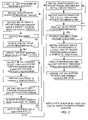
- FIG. 2is a flow diagram of an integrated thin film battery and circuit module manufacturing process.
- an integrated thin film battery and circuit moduleincludes a thin film battery cell that comprises an anode collector, an anode, an electrolyte, a cathode, and a cathode collector.
- the thin film batterycan be deposited upon a polyimide substrate.
- the battery materialscan be deposited through a shadow mask to obtain a specific cell pattern on the polyimide substrate.
- the polyimide substratecan be formed as a multilayer printed circuit board.
- the flexible circuit boardis fabricated using multiple polyimide layers along with necessary embedded horizontally extending conductor traces and vertical extending feedthrough traces.
- one or more battery cellsare disposed between two flexible printed circuits, a top circuit having top circuit conductor traces and a bottom circuit having bottom circuit conductor traces.
- the flexible circuitsare made by repetitively alternately depositing polyimide layers and patterned horizontal conductor traces. After forming the bottom flexible printed circuit, thin film battery cell layers are deposited on the bottom flexible printed circuit through a shadow mask. The shadow mask defines the battery pattern and prevents the deposition of battery cell material in areas where feedthrough holes will be drilled through the flex printed circuit. After depositing the bottom flexible circuit and the battery layers, the top flexible circuit with embedded top conductor traces is deposited over the battery layers, as an integrated module.
- the feedthroughsare drilled and copper is deposited in the feedthroughs for forming vertical running conductor traces.
- the vertical extending copper feed through tracesare connected to the horizontally extending conductor traces.
- the embedded vertical feedthrough and horizontal tracescan be formed for interconnecting top and bottom electronic devices to the thin film battery cells.
- the vertical and horizontal tracesare used to make electrical connections to the battery cell cathode and anode collectors through negative and positive terminals, as well as making electrical contact to the top and bottom electronic devices.
- a manufacturing processis used for forming the integrated battery and circuit module using conventional thin film processes.
- the processis characterized as having three repetitive process loops for forming a plurality of layers of the bottom printed circuit, for forming a plurality of layers of a plurality of battery cells of the battery, and for forming a plurality of layers of the top printed circuit.
- a release structuresuch as a sheet of Mylar, is used as a temporary support structure on which is firstly deposited the first circuit layer.
- a first layer of polyimideis deposited on the release structure.
- a shadow maskis used to deposit bottom circuit traces on the first layer polyimide.
- Another layer of insulating polyimideis deposited on the bottom circuit traces. Consecutive layers of insulating polyimide and patterned conductor traces are deposited until all of the layers of the first bottom circuit are fully deposited.
- the thin film batteryis then deposited on the bottom circuit layer using a shadow mask. Patterned metal is deposited for forming the cathode collector and then cathode. The electrolyte is deposited over the cathode.
- the anode and then the anode collectorare deposited over electrolyte thereby forming a first one of a plurality of thin film battery cells. The process for each cell is repeated until all of the cells are deposited, only the first of which is shown for convenience.
- a top printed circuitis then formed over the thin film battery.
- a plurality of polyimide layers with alternating conductor trace layersare deposited in sequence using shadow masks. When all of the layers are deposited, the last layer is a top conductor trace layer deposited on the top last polyimide layer surface
- the thin film battery moduleis then released from the release structure.
- the moduleis flipped up side down, and a bottom trace layer is deposited on the now exposed bottom surface of the thin film battery module, so as to complete the formation of all of the horizontal conductor traces.
- vertical feedthroughsare drilled through the printed circuit layers of the module and copper feedthrough traces are deposited into the drilled feedthroughs, thereby completing the formation of all of the conductive vertical and horizontal traces that are interconnected as horizontally extending conductor traces and vertically extending feedthrough traces.
- Specific feedthrough traces connected to the middle thin film batteryare designated as positive and negative terminals of the battery.
- top and bottom devicesare bonded to respectively top and bottom surfaces of the thin film battery modules, and electrically bonded to top and bottom surface conductor traces so as to electrically interconnect the top and bottom devices to the network of traces as well as to the thin film battery.
- the top and bottom devicesare heat-producing devices, but are preferably electronic devices, such as voltage regulation and charging electronic devices.
- the present inventionis directed to an integrated thin film battery integrated with thin film printed circuit boards formed as flexible layers.
- Various insulating and conductive materialscan be use to form the top and bottom insulating layers and conductive traces, though polyimide and copper are the preferred materials.
- polyimide and copperare the preferred materials.
Landscapes
- Engineering & Computer Science (AREA)
- Manufacturing & Machinery (AREA)
- Chemical & Material Sciences (AREA)
- Chemical Kinetics & Catalysis (AREA)
- Electrochemistry (AREA)
- General Chemical & Material Sciences (AREA)
- Microelectronics & Electronic Packaging (AREA)
- Secondary Cells (AREA)
- Connection Of Batteries Or Terminals (AREA)
Abstract
Description
Claims (14)
Priority Applications (1)
| Application Number | Priority Date | Filing Date | Title |
|---|---|---|---|
| US10/420,463US7045246B2 (en) | 2003-04-22 | 2003-04-22 | Integrated thin film battery and circuit module |
Applications Claiming Priority (1)
| Application Number | Priority Date | Filing Date | Title |
|---|---|---|---|
| US10/420,463US7045246B2 (en) | 2003-04-22 | 2003-04-22 | Integrated thin film battery and circuit module |
Publications (2)
| Publication Number | Publication Date |
|---|---|
| US20040214079A1 US20040214079A1 (en) | 2004-10-28 |
| US7045246B2true US7045246B2 (en) | 2006-05-16 |
Family
ID=33298510
Family Applications (1)
| Application Number | Title | Priority Date | Filing Date |
|---|---|---|---|
| US10/420,463Expired - Fee RelatedUS7045246B2 (en) | 2003-04-22 | 2003-04-22 | Integrated thin film battery and circuit module |
Country Status (1)
| Country | Link |
|---|---|
| US (1) | US7045246B2 (en) |
Cited By (28)
| Publication number | Priority date | Publication date | Assignee | Title |
|---|---|---|---|---|
| US20020165689A1 (en)* | 2001-04-18 | 2002-11-07 | Callegari Andres C. | Volume body renderer |
| EP2081418A2 (en) | 2008-01-17 | 2009-07-22 | Harris Corporation | Method for making three-dimensional liquid crystal polymer multilayer circuit boards |
| EP2081245A1 (en) | 2008-01-17 | 2009-07-22 | Harris Corporation | Three-dimensional liquid crystal polymer multilayer circuit board including battery and related methods |
| EP2081204A2 (en) | 2008-01-17 | 2009-07-22 | Harris Corporation | Three-dimensional liquid crystal polymer multilayer circuit board including membrane switch and related methods |
| US7959769B2 (en) | 2004-12-08 | 2011-06-14 | Infinite Power Solutions, Inc. | Deposition of LiCoO2 |
| US7993773B2 (en) | 2002-08-09 | 2011-08-09 | Infinite Power Solutions, Inc. | Electrochemical apparatus with barrier layer protected substrate |
| US8021778B2 (en) | 2002-08-09 | 2011-09-20 | Infinite Power Solutions, Inc. | Electrochemical apparatus with barrier layer protected substrate |
| US8062708B2 (en) | 2006-09-29 | 2011-11-22 | Infinite Power Solutions, Inc. | Masking of and material constraint for depositing battery layers on flexible substrates |
| US8197781B2 (en) | 2006-11-07 | 2012-06-12 | Infinite Power Solutions, Inc. | Sputtering target of Li3PO4 and method for producing same |
| US8236443B2 (en) | 2002-08-09 | 2012-08-07 | Infinite Power Solutions, Inc. | Metal film encapsulation |
| US8260203B2 (en) | 2008-09-12 | 2012-09-04 | Infinite Power Solutions, Inc. | Energy device with integral conductive surface for data communication via electromagnetic energy and method thereof |
| US8268488B2 (en) | 2007-12-21 | 2012-09-18 | Infinite Power Solutions, Inc. | Thin film electrolyte for thin film batteries |
| US8350519B2 (en) | 2008-04-02 | 2013-01-08 | Infinite Power Solutions, Inc | Passive over/under voltage control and protection for energy storage devices associated with energy harvesting |
| US8394522B2 (en) | 2002-08-09 | 2013-03-12 | Infinite Power Solutions, Inc. | Robust metal film encapsulation |
| US8404376B2 (en) | 2002-08-09 | 2013-03-26 | Infinite Power Solutions, Inc. | Metal film encapsulation |
| US8431264B2 (en) | 2002-08-09 | 2013-04-30 | Infinite Power Solutions, Inc. | Hybrid thin-film battery |
| US8445130B2 (en) | 2002-08-09 | 2013-05-21 | Infinite Power Solutions, Inc. | Hybrid thin-film battery |
| US8508193B2 (en) | 2008-10-08 | 2013-08-13 | Infinite Power Solutions, Inc. | Environmentally-powered wireless sensor module |
| US8518581B2 (en) | 2008-01-11 | 2013-08-27 | Inifinite Power Solutions, Inc. | Thin film encapsulation for thin film batteries and other devices |
| US8599572B2 (en) | 2009-09-01 | 2013-12-03 | Infinite Power Solutions, Inc. | Printed circuit board with integrated thin film battery |
| US8636876B2 (en) | 2004-12-08 | 2014-01-28 | R. Ernest Demaray | Deposition of LiCoO2 |
| US8728285B2 (en) | 2003-05-23 | 2014-05-20 | Demaray, Llc | Transparent conductive oxides |
| US8906523B2 (en) | 2008-08-11 | 2014-12-09 | Infinite Power Solutions, Inc. | Energy device with integral collector surface for electromagnetic energy harvesting and method thereof |
| US9334557B2 (en) | 2007-12-21 | 2016-05-10 | Sapurast Research Llc | Method for sputter targets for electrolyte films |
| US9528033B2 (en) | 2013-11-13 | 2016-12-27 | R.R. Donnelley & Sons Company | Electrolyte material composition and method |
| US9634296B2 (en) | 2002-08-09 | 2017-04-25 | Sapurast Research Llc | Thin film battery on an integrated circuit or circuit board and method thereof |
| US10637101B2 (en) | 2017-05-03 | 2020-04-28 | International Business Machines Corporation | Miniaturized electronics package with patterned thin film solid state battery |
| US10680277B2 (en) | 2010-06-07 | 2020-06-09 | Sapurast Research Llc | Rechargeable, high-density electrochemical device |
Families Citing this family (19)
| Publication number | Priority date | Publication date | Assignee | Title |
|---|---|---|---|---|
| US20060127752A1 (en)* | 2004-12-09 | 2006-06-15 | Trw Automotive U.S. Llc | Battery with printed circuit |
| TWI419397B (en)* | 2006-05-12 | 2013-12-11 | Infinite Power Solutions Inc | Thin film battery on a semiconductor or semiconductor device apparatus and method |
| CN101207222B (en) | 2006-12-22 | 2011-03-16 | 辉能科技股份有限公司 | power supply system |
| US9166230B1 (en) | 2007-01-12 | 2015-10-20 | Enovix Corporation | Three-dimensional battery having current-reducing devices corresponding to electrodes |
| US8999558B2 (en) | 2007-01-12 | 2015-04-07 | Enovix Corporation | Three-dimensional batteries and methods of manufacturing the same |
| US8691450B1 (en) | 2007-01-12 | 2014-04-08 | Enovix Corporation | Three-dimensional batteries and methods of manufacturing the same |
| US8216712B1 (en) | 2008-01-11 | 2012-07-10 | Enovix Corporation | Anodized metallic battery separator having through-pores |
| US9219288B2 (en)* | 2010-01-05 | 2015-12-22 | Samsung Sdi Co., Ltd. | Secondary battery |
| US9819815B1 (en)* | 2010-02-10 | 2017-11-14 | Amazon Technologies, Inc. | Surface display assembly having proximate active elements |
| US9843027B1 (en) | 2010-09-14 | 2017-12-12 | Enovix Corporation | Battery cell having package anode plate in contact with a plurality of dies |
| US20120177978A1 (en)* | 2011-01-11 | 2012-07-12 | Sungbae Kim | Secondary battery, method of assembling the same, and battery pack including the secondary battery |
| KR101934399B1 (en)* | 2011-11-14 | 2019-01-02 | 삼성에스디아이 주식회사 | Battery pack with protection circuit module and connection terminal portion and electric bike having the same |
| US9257724B2 (en) | 2011-12-23 | 2016-02-09 | Infineon Technologies Ag | Reaction chamber arrangement and a method for forming a reaction chamber arrangement |
| JP6144058B2 (en)* | 2013-01-31 | 2017-06-07 | 新光電気工業株式会社 | Wiring board and method of manufacturing wiring board |
| US20150077981A1 (en)* | 2013-09-16 | 2015-03-19 | Cameron Lanning Cormack | Printed battery for electronic personal vaporizer |
| US10186735B2 (en)* | 2015-12-21 | 2019-01-22 | Intel Corporation | Void filling battery |
| TWI637668B (en)* | 2016-10-13 | 2018-10-01 | 輝能科技股份有限公司 | Logical battery |
| US11417926B2 (en)* | 2018-11-29 | 2022-08-16 | Apple Inc. | Feedthroughs for thin battery cells |
| US12191511B2 (en) | 2019-06-20 | 2025-01-07 | Apple Inc. | Battery cell with serpentine tab |
Citations (5)
| Publication number | Priority date | Publication date | Assignee | Title |
|---|---|---|---|---|
| US5954751A (en)* | 1998-01-15 | 1999-09-21 | Intermedics Inc. | Implantable defibrillator with stacked transistor subassemblies |
| US6152597A (en)* | 1997-06-27 | 2000-11-28 | Potega; Patrick H. | Apparatus for monitoring temperature of a power source |
| US6697694B2 (en)* | 1998-08-26 | 2004-02-24 | Electronic Materials, L.L.C. | Apparatus and method for creating flexible circuits |
| US6916679B2 (en)* | 2002-08-09 | 2005-07-12 | Infinite Power Solutions, Inc. | Methods of and device for encapsulation and termination of electronic devices |
| US6967362B2 (en)* | 2002-09-26 | 2005-11-22 | Samsung Electronics Co., Ltd. | Flexible MEMS transducer and manufacturing method thereof, and flexible MEMS wireless microphone |
- 2003
- 2003-04-22USUS10/420,463patent/US7045246B2/ennot_activeExpired - Fee Related
Patent Citations (5)
| Publication number | Priority date | Publication date | Assignee | Title |
|---|---|---|---|---|
| US6152597A (en)* | 1997-06-27 | 2000-11-28 | Potega; Patrick H. | Apparatus for monitoring temperature of a power source |
| US5954751A (en)* | 1998-01-15 | 1999-09-21 | Intermedics Inc. | Implantable defibrillator with stacked transistor subassemblies |
| US6697694B2 (en)* | 1998-08-26 | 2004-02-24 | Electronic Materials, L.L.C. | Apparatus and method for creating flexible circuits |
| US6916679B2 (en)* | 2002-08-09 | 2005-07-12 | Infinite Power Solutions, Inc. | Methods of and device for encapsulation and termination of electronic devices |
| US6967362B2 (en)* | 2002-09-26 | 2005-11-22 | Samsung Electronics Co., Ltd. | Flexible MEMS transducer and manufacturing method thereof, and flexible MEMS wireless microphone |
Cited By (49)
| Publication number | Priority date | Publication date | Assignee | Title |
|---|---|---|---|---|
| US20020165689A1 (en)* | 2001-04-18 | 2002-11-07 | Callegari Andres C. | Volume body renderer |
| US8445130B2 (en) | 2002-08-09 | 2013-05-21 | Infinite Power Solutions, Inc. | Hybrid thin-film battery |
| US8394522B2 (en) | 2002-08-09 | 2013-03-12 | Infinite Power Solutions, Inc. | Robust metal film encapsulation |
| US9634296B2 (en) | 2002-08-09 | 2017-04-25 | Sapurast Research Llc | Thin film battery on an integrated circuit or circuit board and method thereof |
| US8404376B2 (en) | 2002-08-09 | 2013-03-26 | Infinite Power Solutions, Inc. | Metal film encapsulation |
| US8535396B2 (en) | 2002-08-09 | 2013-09-17 | Infinite Power Solutions, Inc. | Electrochemical apparatus with barrier layer protected substrate |
| US8431264B2 (en) | 2002-08-09 | 2013-04-30 | Infinite Power Solutions, Inc. | Hybrid thin-film battery |
| US7993773B2 (en) | 2002-08-09 | 2011-08-09 | Infinite Power Solutions, Inc. | Electrochemical apparatus with barrier layer protected substrate |
| US9793523B2 (en) | 2002-08-09 | 2017-10-17 | Sapurast Research Llc | Electrochemical apparatus with barrier layer protected substrate |
| US8236443B2 (en) | 2002-08-09 | 2012-08-07 | Infinite Power Solutions, Inc. | Metal film encapsulation |
| US8021778B2 (en) | 2002-08-09 | 2011-09-20 | Infinite Power Solutions, Inc. | Electrochemical apparatus with barrier layer protected substrate |
| US8728285B2 (en) | 2003-05-23 | 2014-05-20 | Demaray, Llc | Transparent conductive oxides |
| US8636876B2 (en) | 2004-12-08 | 2014-01-28 | R. Ernest Demaray | Deposition of LiCoO2 |
| US7959769B2 (en) | 2004-12-08 | 2011-06-14 | Infinite Power Solutions, Inc. | Deposition of LiCoO2 |
| US8062708B2 (en) | 2006-09-29 | 2011-11-22 | Infinite Power Solutions, Inc. | Masking of and material constraint for depositing battery layers on flexible substrates |
| US8197781B2 (en) | 2006-11-07 | 2012-06-12 | Infinite Power Solutions, Inc. | Sputtering target of Li3PO4 and method for producing same |
| US8268488B2 (en) | 2007-12-21 | 2012-09-18 | Infinite Power Solutions, Inc. | Thin film electrolyte for thin film batteries |
| US9334557B2 (en) | 2007-12-21 | 2016-05-10 | Sapurast Research Llc | Method for sputter targets for electrolyte films |
| US9786873B2 (en) | 2008-01-11 | 2017-10-10 | Sapurast Research Llc | Thin film encapsulation for thin film batteries and other devices |
| US8518581B2 (en) | 2008-01-11 | 2013-08-27 | Inifinite Power Solutions, Inc. | Thin film encapsulation for thin film batteries and other devices |
| US20090185357A1 (en)* | 2008-01-17 | 2009-07-23 | Harris Corporation | Three-dimensional liquid crystal polymer multilayer circuit board including membrane switch and related methods |
| US9117602B2 (en) | 2008-01-17 | 2015-08-25 | Harris Corporation | Three-dimensional liquid crystal polymer multilayer circuit board including membrane switch and related methods |
| EP2081418A2 (en) | 2008-01-17 | 2009-07-22 | Harris Corporation | Method for making three-dimensional liquid crystal polymer multilayer circuit boards |
| EP2081245A1 (en) | 2008-01-17 | 2009-07-22 | Harris Corporation | Three-dimensional liquid crystal polymer multilayer circuit board including battery and related methods |
| US20120011715A1 (en)* | 2008-01-17 | 2012-01-19 | Harris Corporation | Three-dimensional liquid crystal polymer multilayer circuit board including battery and related methods |
| US12400810B2 (en) | 2008-01-17 | 2025-08-26 | Harris Corporation | Method for making a three-dimensional liquid crystal polymer electronic device |
| US20090183829A1 (en)* | 2008-01-17 | 2009-07-23 | Harris Corporation | Method for making three-dimensional liquid crystal polymer multilayer circuit boards |
| US9922783B2 (en) | 2008-01-17 | 2018-03-20 | Harris Corporation | Method for making a three-dimensional liquid crystal polymer multilayer circuit board including membrane switch |
| EP2428971A1 (en) | 2008-01-17 | 2012-03-14 | Harris Corporation | Three-dimensional liquid crystal polymer multilayer circuit board including membrane switch and related methods |
| US8778124B2 (en) | 2008-01-17 | 2014-07-15 | Harris Corporation | Method for making three-dimensional liquid crystal polymer multilayer circuit boards |
| US10818448B2 (en) | 2008-01-17 | 2020-10-27 | Harris Corporation | Method for making a three-dimensional liquid crystal polymer multilayer circuit board including membrane switch including air |
| US20090186169A1 (en)* | 2008-01-17 | 2009-07-23 | Harris Corporation | Three-dimensional liquid crystal polymer multilayer circuit board including battery and related methods |
| US11657989B2 (en) | 2008-01-17 | 2023-05-23 | Harris Corporation | Method for making a three-dimensional liquid crystal polymer multilayer circuit board including membrane switch including air |
| EP2081204A2 (en) | 2008-01-17 | 2009-07-22 | Harris Corporation | Three-dimensional liquid crystal polymer multilayer circuit board including membrane switch and related methods |
| US8350519B2 (en) | 2008-04-02 | 2013-01-08 | Infinite Power Solutions, Inc | Passive over/under voltage control and protection for energy storage devices associated with energy harvesting |
| US8906523B2 (en) | 2008-08-11 | 2014-12-09 | Infinite Power Solutions, Inc. | Energy device with integral collector surface for electromagnetic energy harvesting and method thereof |
| US8260203B2 (en) | 2008-09-12 | 2012-09-04 | Infinite Power Solutions, Inc. | Energy device with integral conductive surface for data communication via electromagnetic energy and method thereof |
| US8508193B2 (en) | 2008-10-08 | 2013-08-13 | Infinite Power Solutions, Inc. | Environmentally-powered wireless sensor module |
| US9532453B2 (en) | 2009-09-01 | 2016-12-27 | Sapurast Research Llc | Printed circuit board with integrated thin film battery |
| US10080291B2 (en) | 2009-09-01 | 2018-09-18 | Sapurast Research Llc | Printed circuit board with integrated thin film battery |
| US8599572B2 (en) | 2009-09-01 | 2013-12-03 | Infinite Power Solutions, Inc. | Printed circuit board with integrated thin film battery |
| US10680277B2 (en) | 2010-06-07 | 2020-06-09 | Sapurast Research Llc | Rechargeable, high-density electrochemical device |
| US10106710B2 (en) | 2013-11-13 | 2018-10-23 | R.R. Donnelley & Sons Company | Insulator material composition and method |
| US9718997B2 (en) | 2013-11-13 | 2017-08-01 | R.R. Donnelley & Sons Company | Battery |
| US9528033B2 (en) | 2013-11-13 | 2016-12-27 | R.R. Donnelley & Sons Company | Electrolyte material composition and method |
| US10637101B2 (en) | 2017-05-03 | 2020-04-28 | International Business Machines Corporation | Miniaturized electronics package with patterned thin film solid state battery |
| US10651507B2 (en) | 2017-05-03 | 2020-05-12 | International Business Machines Corporation | Miniaturized electronics package with patterned thin film solid state battery |
| US11539081B2 (en) | 2017-05-03 | 2022-12-27 | International Business Machines Corporation | Miniaturized electronics package with patterned thin film solid state battery |
| US11539080B2 (en) | 2017-05-03 | 2022-12-27 | International Business Machines Corporation | Miniaturized electronics package with patterned thin film solid state battery |
Also Published As
| Publication number | Publication date |
|---|---|
| US20040214079A1 (en) | 2004-10-28 |
Similar Documents
| Publication | Publication Date | Title |
|---|---|---|
| US7045246B2 (en) | Integrated thin film battery and circuit module | |
| US7624499B2 (en) | Flexible circuit having an integrally formed battery | |
| KR101102116B1 (en) | Digital battery | |
| US5073684A (en) | Sheet type storage battery and printed wiring board containing the same | |
| US7569290B2 (en) | Flat panel direct methanol fuel cell and method for making the same | |
| US20090278503A1 (en) | Thin-film battery equipment | |
| KR100592152B1 (en) | Portable Electronic Devices Including Battery Supply Parts | |
| US6593669B1 (en) | Rechargeable or non rechargeable smart battery cell and process for the production of such a cell | |
| US6300158B1 (en) | Integrated solar power module | |
| US20070172735A1 (en) | Thin-film Battery | |
| US20070184968A1 (en) | Flat panel direct methanol fuel cell and method of making the same | |
| US20090035638A1 (en) | Fuel cell module | |
| AU2002347874A1 (en) | Digital battery | |
| WO2003032341A3 (en) | Integrally formed energy storage device and method of fabrication | |
| US10637105B2 (en) | Battery embedded architecture for supplying appropriate voltage | |
| EP3349254A1 (en) | Solar cell module and portable charger | |
| TWI274434B (en) | Structure of integrated packed fuel cell | |
| JP3448848B2 (en) | Mounting structure of stacked battery on substrate | |
| JPH02121384A (en) | Printed wiring board with built-in battery | |
| Bedjaoui et al. | Interconnection of flexible lithium thin film batteries for systems-in-foil | |
| Clark et al. | Innovative flexible lightweight thin-film power generation and storage for space applications | |
| CN218526494U (en) | Circuit board with charge-discharge function | |
| JP3126831U (en) | Fuel cell device with circuit element | |
| JPH02121385A (en) | Printed wiring board with built-in storage battery | |
| US11916157B2 (en) | Hybrid-energy apparatus, system, and method therefor |
Legal Events
| Date | Code | Title | Description |
|---|---|---|---|
| AS | Assignment | Owner name:AEROSPACE CORPORATION, THE, CALIFORNIA Free format text:ASSIGNMENT OF ASSIGNORS INTEREST;ASSIGNORS:SIMBURGER, EDWARD J.;MATSUMOTO, JAMES H.;REEL/FRAME:013993/0218 Effective date:20030415 Owner name:SRS TECHNOLOGIES, INC., ALABAMA Free format text:ASSIGNMENT OF ASSIGNORS INTEREST;ASSIGNOR:GIEROW, PAUL A.;REEL/FRAME:013993/0116 Effective date:20030417 | |
| AS | Assignment | Owner name:MANTECH SRS TECHNOLOGIES, INC., ALABAMA Free format text:ASSIGNMENT OF ASSIGNORS INTEREST;ASSIGNOR:SRS TECHNOLOGIES, INC.;REEL/FRAME:019432/0004 Effective date:20070612 | |
| AS | Assignment | Owner name:NEXOLVE CORPORATION, ALABAMA Free format text:ASSIGNMENT OF ASSIGNORS INTEREST;ASSIGNOR:MANTECH SRS TECHNOLOGIES, INC.;REEL/FRAME:022354/0914 Effective date:20090225 | |
| FPAY | Fee payment | Year of fee payment:4 | |
| FEPP | Fee payment procedure | Free format text:PAYOR NUMBER ASSIGNED (ORIGINAL EVENT CODE: ASPN); ENTITY STATUS OF PATENT OWNER: LARGE ENTITY | |
| FPAY | Fee payment | Year of fee payment:8 | |
| FEPP | Fee payment procedure | Free format text:MAINTENANCE FEE REMINDER MAILED (ORIGINAL EVENT CODE: REM.) | |
| LAPS | Lapse for failure to pay maintenance fees | Free format text:PATENT EXPIRED FOR FAILURE TO PAY MAINTENANCE FEES (ORIGINAL EVENT CODE: EXP.) | |
| STCH | Information on status: patent discontinuation | Free format text:PATENT EXPIRED DUE TO NONPAYMENT OF MAINTENANCE FEES UNDER 37 CFR 1.362 | |
| AS | Assignment | Owner name:NEXOLVE HOLDING COMPANY, LLC, ALABAMA Free format text:ASSIGNMENT OF ASSIGNORS INTEREST;ASSIGNOR:NEXOLVE CORPORATION;REEL/FRAME:049372/0972 Effective date:20180415 |