US7043815B2 - Method for applying flowable materials - Google Patents
Method for applying flowable materialsDownload PDFInfo
- Publication number
- US7043815B2 US7043815B2US10/342,025US34202503AUS7043815B2US 7043815 B2US7043815 B2US 7043815B2US 34202503 AUS34202503 AUS 34202503AUS 7043815 B2US7043815 B2US 7043815B2
- Authority
- US
- United States
- Prior art keywords
- flowable material
- extruder
- flowable
- components
- component
- Prior art date
- Legal status (The legal status is an assumption and is not a legal conclusion. Google has not performed a legal analysis and makes no representation as to the accuracy of the status listed.)
- Expired - Lifetime, expires
Links
- 239000000463materialSubstances0.000titleclaimsabstractdescription425
- 230000009969flowable effectEffects0.000titleclaimsabstractdescription261
- 238000000034methodMethods0.000titleclaimsabstractdescription63
- 238000004519manufacturing processMethods0.000claimsabstractdescription30
- 239000008188pelletSubstances0.000claimsdescription52
- 238000001125extrusionMethods0.000claimsdescription29
- 239000011324beadSubstances0.000claimsdescription22
- 238000010438heat treatmentMethods0.000claimsdescription20
- 239000000853adhesiveSubstances0.000claimsdescription18
- 230000001070adhesive effectEffects0.000claimsdescription18
- 229920000642polymerPolymers0.000claimsdescription13
- 239000002184metalSubstances0.000claimsdescription12
- 229910052751metalInorganic materials0.000claimsdescription12
- 238000004891communicationMethods0.000claimsdescription10
- 230000033001locomotionEffects0.000claimsdescription9
- 239000000565sealantSubstances0.000claimsdescription9
- 239000003973paintSubstances0.000claimsdescription8
- 229920005989resinPolymers0.000claimsdescription8
- 239000011347resinSubstances0.000claimsdescription8
- 230000008859changeEffects0.000claimsdescription6
- 239000000356contaminantSubstances0.000claimsdescription6
- 239000004615ingredientSubstances0.000claimsdescription6
- 239000004593EpoxySubstances0.000claimsdescription5
- 238000009826distributionMethods0.000claimsdescription5
- 238000010422paintingMethods0.000claimsdescription5
- 239000004033plasticSubstances0.000claimsdescription5
- 229920003023plasticPolymers0.000claimsdescription5
- 239000002904solventSubstances0.000claimsdescription5
- 239000000945fillerSubstances0.000claimsdescription3
- 230000002441reversible effectEffects0.000claimsdescription3
- 239000002318adhesion promoterSubstances0.000claimsdescription2
- 239000003000extruded plasticSubstances0.000claimsdescription2
- 239000000446fuelSubstances0.000claimsdescription2
- 239000002991molded plasticSubstances0.000claimsdescription2
- 229920000573polyethylenePolymers0.000claims2
- 229910000831SteelInorganic materials0.000claims1
- 229910052782aluminiumInorganic materials0.000claims1
- XAGFODPZIPBFFR-UHFFFAOYSA-NaluminiumChemical compound[Al]XAGFODPZIPBFFR-UHFFFAOYSA-N0.000claims1
- 239000010959steelSubstances0.000claims1
- 238000005406washingMethods0.000claims1
- 230000015572biosynthetic processEffects0.000abstractdescription2
- 238000011282treatmentMethods0.000abstractdescription2
- 239000000758substrateSubstances0.000description16
- 230000007246mechanismEffects0.000description11
- 210000002381plasmaAnatomy0.000description11
- 230000008569processEffects0.000description11
- 239000000126substanceSubstances0.000description11
- 239000000203mixtureSubstances0.000description10
- 230000004044responseEffects0.000description10
- 239000012812sealant materialSubstances0.000description10
- 239000002987primer (paints)Substances0.000description9
- 239000012535impuritySubstances0.000description8
- 239000006260foamSubstances0.000description7
- 230000006870functionEffects0.000description7
- 238000012545processingMethods0.000description7
- 230000001965increasing effectEffects0.000description6
- 239000007787solidSubstances0.000description6
- 238000010521absorption reactionMethods0.000description5
- 230000004913activationEffects0.000description5
- 238000009472formulationMethods0.000description5
- 239000003921oilSubstances0.000description5
- 230000000704physical effectEffects0.000description5
- 238000005260corrosionMethods0.000description4
- 230000007797corrosionEffects0.000description4
- 238000007789sealingMethods0.000description4
- 229920001897terpolymerPolymers0.000description4
- WSFSSNUMVMOOMR-UHFFFAOYSA-NFormaldehydeChemical compoundO=CWSFSSNUMVMOOMR-UHFFFAOYSA-N0.000description3
- 238000006243chemical reactionMethods0.000description3
- 238000013016dampingMethods0.000description3
- 238000013461designMethods0.000description3
- 239000001993waxSubstances0.000description3
- VGGSQFUCUMXWEO-UHFFFAOYSA-NEtheneChemical compoundC=CVGGSQFUCUMXWEO-UHFFFAOYSA-N0.000description2
- 239000005977EthyleneSubstances0.000description2
- 230000009471actionEffects0.000description2
- 230000008901benefitEffects0.000description2
- 238000004140cleaningMethods0.000description2
- 230000006835compressionEffects0.000description2
- 239000000470constituentSubstances0.000description2
- 229920001577copolymerPolymers0.000description2
- 229920001038ethylene copolymerPolymers0.000description2
- 239000012530fluidSubstances0.000description2
- 230000005484gravityEffects0.000description2
- 229930195733hydrocarbonNatural products0.000description2
- 150000002430hydrocarbonsChemical class0.000description2
- 230000001976improved effectEffects0.000description2
- 238000002156mixingMethods0.000description2
- 239000000178monomerSubstances0.000description2
- 229920000098polyolefinPolymers0.000description2
- 238000003908quality control methodMethods0.000description2
- 230000009467reductionEffects0.000description2
- 230000011664signalingEffects0.000description2
- 125000006850spacer groupChemical group0.000description2
- 229920001169thermoplasticPolymers0.000description2
- 239000004416thermosoftening plasticSubstances0.000description2
- 239000011800void materialSubstances0.000description2
- 239000004711α-olefinSubstances0.000description2
- 239000004604Blowing AgentSubstances0.000description1
- 239000004215Carbon black (E152)Substances0.000description1
- 229920002943EPDM rubberPolymers0.000description1
- ISWSIDIOOBJBQZ-UHFFFAOYSA-NPhenolChemical compoundOC1=CC=CC=C1ISWSIDIOOBJBQZ-UHFFFAOYSA-N0.000description1
- 125000004018acid anhydride groupChemical group0.000description1
- 239000012190activatorSubstances0.000description1
- 230000001154acute effectEffects0.000description1
- 238000007792additionMethods0.000description1
- 238000013459approachMethods0.000description1
- 230000004888barrier functionEffects0.000description1
- 229920005601base polymerPolymers0.000description1
- 230000005540biological transmissionEffects0.000description1
- 230000000903blocking effectEffects0.000description1
- 238000007664blowingMethods0.000description1
- DQXBYHZEEUGOBF-UHFFFAOYSA-Nbut-3-enoic acid;etheneChemical compoundC=C.OC(=O)CC=CDQXBYHZEEUGOBF-UHFFFAOYSA-N0.000description1
- 210000004027cellAnatomy0.000description1
- 239000003795chemical substances by applicationSubstances0.000description1
- 238000000576coating methodMethods0.000description1
- 150000001875compoundsChemical class0.000description1
- 238000007906compressionMethods0.000description1
- 238000000748compression mouldingMethods0.000description1
- 230000003750conditioning effectEffects0.000description1
- 238000010276constructionMethods0.000description1
- 230000008878couplingEffects0.000description1
- 238000010168coupling processMethods0.000description1
- 238000005859coupling reactionMethods0.000description1
- 238000004132cross linkingMethods0.000description1
- 238000005238degreasingMethods0.000description1
- 238000010586diagramMethods0.000description1
- 238000001035dryingMethods0.000description1
- 230000000694effectsEffects0.000description1
- 229920001971elastomerPolymers0.000description1
- 238000005516engineering processMethods0.000description1
- 230000002708enhancing effectEffects0.000description1
- 239000003822epoxy resinSubstances0.000description1
- 239000005038ethylene vinyl acetateSubstances0.000description1
- 238000001704evaporationMethods0.000description1
- 230000001747exhibiting effectEffects0.000description1
- 239000004744fabricSubstances0.000description1
- 230000009477glass transitionEffects0.000description1
- 239000008187granular materialSubstances0.000description1
- 239000004519greaseSubstances0.000description1
- 238000000227grindingMethods0.000description1
- LNEPOXFFQSENCJ-UHFFFAOYSA-NhaloperidolChemical compoundC1CC(O)(C=2C=CC(Cl)=CC=2)CCN1CCCC(=O)C1=CC=C(F)C=C1LNEPOXFFQSENCJ-UHFFFAOYSA-N0.000description1
- 230000006872improvementEffects0.000description1
- 238000001746injection mouldingMethods0.000description1
- 230000003993interactionEffects0.000description1
- 230000002452interceptive effectEffects0.000description1
- 230000001788irregularEffects0.000description1
- 239000007788liquidSubstances0.000description1
- 238000011068loading methodMethods0.000description1
- 239000000314lubricantSubstances0.000description1
- 238000012423maintenanceMethods0.000description1
- 230000013011matingEffects0.000description1
- 239000000155meltSubstances0.000description1
- 238000002844meltingMethods0.000description1
- 230000008018meltingEffects0.000description1
- 150000002739metalsChemical class0.000description1
- 238000012986modificationMethods0.000description1
- 230000004048modificationEffects0.000description1
- 238000012544monitoring processMethods0.000description1
- 238000000465mouldingMethods0.000description1
- 239000002245particleSubstances0.000description1
- 125000000951phenoxy groupChemical group[H]C1=C([H])C([H])=C(O*)C([H])=C1[H]0.000description1
- 239000004014plasticizerSubstances0.000description1
- 238000005498polishingMethods0.000description1
- 229920001200poly(ethylene-vinyl acetate)Polymers0.000description1
- 229920002857polybutadienePolymers0.000description1
- 229920001083polybutenePolymers0.000description1
- 229920000647polyepoxidePolymers0.000description1
- 239000004814polyurethaneSubstances0.000description1
- 229920002635polyurethanePolymers0.000description1
- 238000010944pre-mature reactionyMethods0.000description1
- 238000002360preparation methodMethods0.000description1
- 239000013615primerSubstances0.000description1
- 230000037452primingEffects0.000description1
- 239000010734process oilSubstances0.000description1
- 230000001737promoting effectEffects0.000description1
- 230000005855radiationEffects0.000description1
- 239000000376reactantSubstances0.000description1
- 230000009257reactivityEffects0.000description1
- 230000003014reinforcing effectEffects0.000description1
- 239000005060rubberSubstances0.000description1
- 238000007665saggingMethods0.000description1
- 150000003384small moleculesChemical class0.000description1
- 239000011343solid materialSubstances0.000description1
- 230000003381solubilizing effectEffects0.000description1
- 239000004616structural foamSubstances0.000description1
- 230000008093supporting effectEffects0.000description1
- 239000000725suspensionSubstances0.000description1
- 239000012815thermoplastic materialSubstances0.000description1
- 230000001960triggered effectEffects0.000description1
- 230000000007visual effectEffects0.000description1
- XLYOFNOQVPJJNP-UHFFFAOYSA-NwaterSubstancesOXLYOFNOQVPJJNP-UHFFFAOYSA-N0.000description1
Images


Classifications
- B—PERFORMING OPERATIONS; TRANSPORTING
- B05—SPRAYING OR ATOMISING IN GENERAL; APPLYING FLUENT MATERIALS TO SURFACES, IN GENERAL
- B05D—PROCESSES FOR APPLYING FLUENT MATERIALS TO SURFACES, IN GENERAL
- B05D1/00—Processes for applying liquids or other fluent materials
- B05D1/26—Processes for applying liquids or other fluent materials performed by applying the liquid or other fluent material from an outlet device in contact with, or almost in contact with, the surface
- B05D1/265—Extrusion coatings
- B—PERFORMING OPERATIONS; TRANSPORTING
- B29—WORKING OF PLASTICS; WORKING OF SUBSTANCES IN A PLASTIC STATE IN GENERAL
- B29C—SHAPING OR JOINING OF PLASTICS; SHAPING OF MATERIAL IN A PLASTIC STATE, NOT OTHERWISE PROVIDED FOR; AFTER-TREATMENT OF THE SHAPED PRODUCTS, e.g. REPAIRING
- B29C48/00—Extrusion moulding, i.e. expressing the moulding material through a die or nozzle which imparts the desired form; Apparatus therefor
- B29C48/03—Extrusion moulding, i.e. expressing the moulding material through a die or nozzle which imparts the desired form; Apparatus therefor characterised by the shape of the extruded material at extrusion
- B29C48/04—Particle-shaped
- B—PERFORMING OPERATIONS; TRANSPORTING
- B29—WORKING OF PLASTICS; WORKING OF SUBSTANCES IN A PLASTIC STATE IN GENERAL
- B29C—SHAPING OR JOINING OF PLASTICS; SHAPING OF MATERIAL IN A PLASTIC STATE, NOT OTHERWISE PROVIDED FOR; AFTER-TREATMENT OF THE SHAPED PRODUCTS, e.g. REPAIRING
- B29C48/00—Extrusion moulding, i.e. expressing the moulding material through a die or nozzle which imparts the desired form; Apparatus therefor
- B29C48/15—Extrusion moulding, i.e. expressing the moulding material through a die or nozzle which imparts the desired form; Apparatus therefor incorporating preformed parts or layers, e.g. extrusion moulding around inserts
- B29C48/154—Coating solid articles, i.e. non-hollow articles
- B29C48/155—Partial coating thereof
- B—PERFORMING OPERATIONS; TRANSPORTING
- B29—WORKING OF PLASTICS; WORKING OF SUBSTANCES IN A PLASTIC STATE IN GENERAL
- B29C—SHAPING OR JOINING OF PLASTICS; SHAPING OF MATERIAL IN A PLASTIC STATE, NOT OTHERWISE PROVIDED FOR; AFTER-TREATMENT OF THE SHAPED PRODUCTS, e.g. REPAIRING
- B29C48/00—Extrusion moulding, i.e. expressing the moulding material through a die or nozzle which imparts the desired form; Apparatus therefor
- B29C48/25—Component parts, details or accessories; Auxiliary operations
- B29C48/256—Exchangeable extruder parts
- B29C48/2562—Mounting or handling of the die
- B—PERFORMING OPERATIONS; TRANSPORTING
- B29—WORKING OF PLASTICS; WORKING OF SUBSTANCES IN A PLASTIC STATE IN GENERAL
- B29C—SHAPING OR JOINING OF PLASTICS; SHAPING OF MATERIAL IN A PLASTIC STATE, NOT OTHERWISE PROVIDED FOR; AFTER-TREATMENT OF THE SHAPED PRODUCTS, e.g. REPAIRING
- B29C48/00—Extrusion moulding, i.e. expressing the moulding material through a die or nozzle which imparts the desired form; Apparatus therefor
- B29C48/25—Component parts, details or accessories; Auxiliary operations
- B29C48/266—Means for allowing relative movements between the apparatus parts, e.g. for twisting the extruded article or for moving the die along a surface to be coated
- B—PERFORMING OPERATIONS; TRANSPORTING
- B29—WORKING OF PLASTICS; WORKING OF SUBSTANCES IN A PLASTIC STATE IN GENERAL
- B29C—SHAPING OR JOINING OF PLASTICS; SHAPING OF MATERIAL IN A PLASTIC STATE, NOT OTHERWISE PROVIDED FOR; AFTER-TREATMENT OF THE SHAPED PRODUCTS, e.g. REPAIRING
- B29C48/00—Extrusion moulding, i.e. expressing the moulding material through a die or nozzle which imparts the desired form; Apparatus therefor
- B29C48/25—Component parts, details or accessories; Auxiliary operations
- B29C48/92—Measuring, controlling or regulating
- B—PERFORMING OPERATIONS; TRANSPORTING
- B05—SPRAYING OR ATOMISING IN GENERAL; APPLYING FLUENT MATERIALS TO SURFACES, IN GENERAL
- B05D—PROCESSES FOR APPLYING FLUENT MATERIALS TO SURFACES, IN GENERAL
- B05D3/00—Pretreatment of surfaces to which liquids or other fluent materials are to be applied; After-treatment of applied coatings, e.g. intermediate treating of an applied coating preparatory to subsequent applications of liquids or other fluent materials
- B05D3/02—Pretreatment of surfaces to which liquids or other fluent materials are to be applied; After-treatment of applied coatings, e.g. intermediate treating of an applied coating preparatory to subsequent applications of liquids or other fluent materials by baking
- B05D3/0218—Pretreatment, e.g. heating the substrate
- B05D3/0227—Pretreatment, e.g. heating the substrate with IR heaters
- B—PERFORMING OPERATIONS; TRANSPORTING
- B05—SPRAYING OR ATOMISING IN GENERAL; APPLYING FLUENT MATERIALS TO SURFACES, IN GENERAL
- B05D—PROCESSES FOR APPLYING FLUENT MATERIALS TO SURFACES, IN GENERAL
- B05D3/00—Pretreatment of surfaces to which liquids or other fluent materials are to be applied; After-treatment of applied coatings, e.g. intermediate treating of an applied coating preparatory to subsequent applications of liquids or other fluent materials
- B05D3/06—Pretreatment of surfaces to which liquids or other fluent materials are to be applied; After-treatment of applied coatings, e.g. intermediate treating of an applied coating preparatory to subsequent applications of liquids or other fluent materials by exposure to radiation
- B05D3/061—Pretreatment of surfaces to which liquids or other fluent materials are to be applied; After-treatment of applied coatings, e.g. intermediate treating of an applied coating preparatory to subsequent applications of liquids or other fluent materials by exposure to radiation using U.V.
- B05D3/062—Pretreatment
- B—PERFORMING OPERATIONS; TRANSPORTING
- B05—SPRAYING OR ATOMISING IN GENERAL; APPLYING FLUENT MATERIALS TO SURFACES, IN GENERAL
- B05D—PROCESSES FOR APPLYING FLUENT MATERIALS TO SURFACES, IN GENERAL
- B05D3/00—Pretreatment of surfaces to which liquids or other fluent materials are to be applied; After-treatment of applied coatings, e.g. intermediate treating of an applied coating preparatory to subsequent applications of liquids or other fluent materials
- B05D3/14—Pretreatment of surfaces to which liquids or other fluent materials are to be applied; After-treatment of applied coatings, e.g. intermediate treating of an applied coating preparatory to subsequent applications of liquids or other fluent materials by electrical means
- B05D3/141—Plasma treatment
- B05D3/142—Pretreatment
- B—PERFORMING OPERATIONS; TRANSPORTING
- B29—WORKING OF PLASTICS; WORKING OF SUBSTANCES IN A PLASTIC STATE IN GENERAL
- B29C—SHAPING OR JOINING OF PLASTICS; SHAPING OF MATERIAL IN A PLASTIC STATE, NOT OTHERWISE PROVIDED FOR; AFTER-TREATMENT OF THE SHAPED PRODUCTS, e.g. REPAIRING
- B29C2948/00—Indexing scheme relating to extrusion moulding
- B29C2948/92—Measuring, controlling or regulating
- B29C2948/92504—Controlled parameter
- B29C2948/9258—Velocity
- B29C2948/9259—Angular velocity
- B—PERFORMING OPERATIONS; TRANSPORTING
- B29—WORKING OF PLASTICS; WORKING OF SUBSTANCES IN A PLASTIC STATE IN GENERAL
- B29C—SHAPING OR JOINING OF PLASTICS; SHAPING OF MATERIAL IN A PLASTIC STATE, NOT OTHERWISE PROVIDED FOR; AFTER-TREATMENT OF THE SHAPED PRODUCTS, e.g. REPAIRING
- B29C2948/00—Indexing scheme relating to extrusion moulding
- B29C2948/92—Measuring, controlling or regulating
- B29C2948/92504—Controlled parameter
- B29C2948/9258—Velocity
- B29C2948/926—Flow or feed rate
- B—PERFORMING OPERATIONS; TRANSPORTING
- B29—WORKING OF PLASTICS; WORKING OF SUBSTANCES IN A PLASTIC STATE IN GENERAL
- B29C—SHAPING OR JOINING OF PLASTICS; SHAPING OF MATERIAL IN A PLASTIC STATE, NOT OTHERWISE PROVIDED FOR; AFTER-TREATMENT OF THE SHAPED PRODUCTS, e.g. REPAIRING
- B29C2948/00—Indexing scheme relating to extrusion moulding
- B29C2948/92—Measuring, controlling or regulating
- B29C2948/92819—Location or phase of control
- B29C2948/92857—Extrusion unit
- B29C2948/92876—Feeding, melting, plasticising or pumping zones, e.g. the melt itself
- B29C2948/92885—Screw or gear
- B—PERFORMING OPERATIONS; TRANSPORTING
- B29—WORKING OF PLASTICS; WORKING OF SUBSTANCES IN A PLASTIC STATE IN GENERAL
- B29C—SHAPING OR JOINING OF PLASTICS; SHAPING OF MATERIAL IN A PLASTIC STATE, NOT OTHERWISE PROVIDED FOR; AFTER-TREATMENT OF THE SHAPED PRODUCTS, e.g. REPAIRING
- B29C2948/00—Indexing scheme relating to extrusion moulding
- B29C2948/92—Measuring, controlling or regulating
- B29C2948/92819—Location or phase of control
- B29C2948/92857—Extrusion unit
- B29C2948/92904—Die; Nozzle zone
- B—PERFORMING OPERATIONS; TRANSPORTING
- B29—WORKING OF PLASTICS; WORKING OF SUBSTANCES IN A PLASTIC STATE IN GENERAL
- B29C—SHAPING OR JOINING OF PLASTICS; SHAPING OF MATERIAL IN A PLASTIC STATE, NOT OTHERWISE PROVIDED FOR; AFTER-TREATMENT OF THE SHAPED PRODUCTS, e.g. REPAIRING
- B29C48/00—Extrusion moulding, i.e. expressing the moulding material through a die or nozzle which imparts the desired form; Apparatus therefor
- B29C48/03—Extrusion moulding, i.e. expressing the moulding material through a die or nozzle which imparts the desired form; Apparatus therefor characterised by the shape of the extruded material at extrusion
- B29C48/07—Flat, e.g. panels
- B—PERFORMING OPERATIONS; TRANSPORTING
- B29—WORKING OF PLASTICS; WORKING OF SUBSTANCES IN A PLASTIC STATE IN GENERAL
- B29C—SHAPING OR JOINING OF PLASTICS; SHAPING OF MATERIAL IN A PLASTIC STATE, NOT OTHERWISE PROVIDED FOR; AFTER-TREATMENT OF THE SHAPED PRODUCTS, e.g. REPAIRING
- B29C48/00—Extrusion moulding, i.e. expressing the moulding material through a die or nozzle which imparts the desired form; Apparatus therefor
- B29C48/03—Extrusion moulding, i.e. expressing the moulding material through a die or nozzle which imparts the desired form; Apparatus therefor characterised by the shape of the extruded material at extrusion
- B29C48/131—Curved articles
- B—PERFORMING OPERATIONS; TRANSPORTING
- B29—WORKING OF PLASTICS; WORKING OF SUBSTANCES IN A PLASTIC STATE IN GENERAL
- B29C—SHAPING OR JOINING OF PLASTICS; SHAPING OF MATERIAL IN A PLASTIC STATE, NOT OTHERWISE PROVIDED FOR; AFTER-TREATMENT OF THE SHAPED PRODUCTS, e.g. REPAIRING
- B29C48/00—Extrusion moulding, i.e. expressing the moulding material through a die or nozzle which imparts the desired form; Apparatus therefor
- B29C48/25—Component parts, details or accessories; Auxiliary operations
- B29C48/285—Feeding the extrusion material to the extruder
- Y—GENERAL TAGGING OF NEW TECHNOLOGICAL DEVELOPMENTS; GENERAL TAGGING OF CROSS-SECTIONAL TECHNOLOGIES SPANNING OVER SEVERAL SECTIONS OF THE IPC; TECHNICAL SUBJECTS COVERED BY FORMER USPC CROSS-REFERENCE ART COLLECTIONS [XRACs] AND DIGESTS
- Y10—TECHNICAL SUBJECTS COVERED BY FORMER USPC
- Y10T—TECHNICAL SUBJECTS COVERED BY FORMER US CLASSIFICATION
- Y10T29/00—Metal working
- Y10T29/49—Method of mechanical manufacture
- Y10T29/49764—Method of mechanical manufacture with testing or indicating
- Y10T29/49778—Method of mechanical manufacture with testing or indicating with aligning, guiding, or instruction
- Y—GENERAL TAGGING OF NEW TECHNOLOGICAL DEVELOPMENTS; GENERAL TAGGING OF CROSS-SECTIONAL TECHNOLOGIES SPANNING OVER SEVERAL SECTIONS OF THE IPC; TECHNICAL SUBJECTS COVERED BY FORMER USPC CROSS-REFERENCE ART COLLECTIONS [XRACs] AND DIGESTS
- Y10—TECHNICAL SUBJECTS COVERED BY FORMER USPC
- Y10T—TECHNICAL SUBJECTS COVERED BY FORMER US CLASSIFICATION
- Y10T29/00—Metal working
- Y10T29/49—Method of mechanical manufacture
- Y10T29/49826—Assembling or joining
- Y10T29/49828—Progressively advancing of work assembly station or assembled portion of work
- Y10T29/49829—Advancing work to successive stations [i.e., assembly line]
- Y—GENERAL TAGGING OF NEW TECHNOLOGICAL DEVELOPMENTS; GENERAL TAGGING OF CROSS-SECTIONAL TECHNOLOGIES SPANNING OVER SEVERAL SECTIONS OF THE IPC; TECHNICAL SUBJECTS COVERED BY FORMER USPC CROSS-REFERENCE ART COLLECTIONS [XRACs] AND DIGESTS
- Y10—TECHNICAL SUBJECTS COVERED BY FORMER USPC
- Y10T—TECHNICAL SUBJECTS COVERED BY FORMER US CLASSIFICATION
- Y10T29/00—Metal working
- Y10T29/49—Method of mechanical manufacture
- Y10T29/49826—Assembling or joining
- Y10T29/49885—Assembling or joining with coating before or during assembling
- Y—GENERAL TAGGING OF NEW TECHNOLOGICAL DEVELOPMENTS; GENERAL TAGGING OF CROSS-SECTIONAL TECHNOLOGIES SPANNING OVER SEVERAL SECTIONS OF THE IPC; TECHNICAL SUBJECTS COVERED BY FORMER USPC CROSS-REFERENCE ART COLLECTIONS [XRACs] AND DIGESTS
- Y10—TECHNICAL SUBJECTS COVERED BY FORMER USPC
- Y10T—TECHNICAL SUBJECTS COVERED BY FORMER US CLASSIFICATION
- Y10T29/00—Metal working
- Y10T29/49—Method of mechanical manufacture
- Y10T29/49826—Assembling or joining
- Y10T29/49888—Subsequently coating
- Y—GENERAL TAGGING OF NEW TECHNOLOGICAL DEVELOPMENTS; GENERAL TAGGING OF CROSS-SECTIONAL TECHNOLOGIES SPANNING OVER SEVERAL SECTIONS OF THE IPC; TECHNICAL SUBJECTS COVERED BY FORMER USPC CROSS-REFERENCE ART COLLECTIONS [XRACs] AND DIGESTS
- Y10—TECHNICAL SUBJECTS COVERED BY FORMER USPC
- Y10T—TECHNICAL SUBJECTS COVERED BY FORMER US CLASSIFICATION
- Y10T29/00—Metal working
- Y10T29/49—Method of mechanical manufacture
- Y10T29/4998—Combined manufacture including applying or shaping of fluent material
- Y10T29/49982—Coating
- Y—GENERAL TAGGING OF NEW TECHNOLOGICAL DEVELOPMENTS; GENERAL TAGGING OF CROSS-SECTIONAL TECHNOLOGIES SPANNING OVER SEVERAL SECTIONS OF THE IPC; TECHNICAL SUBJECTS COVERED BY FORMER USPC CROSS-REFERENCE ART COLLECTIONS [XRACs] AND DIGESTS
- Y10—TECHNICAL SUBJECTS COVERED BY FORMER USPC
- Y10T—TECHNICAL SUBJECTS COVERED BY FORMER US CLASSIFICATION
- Y10T29/00—Metal working
- Y10T29/53—Means to assemble or disassemble
- Y10T29/534—Multiple station assembly or disassembly apparatus
- Y10T29/53404—Multiple station assembly or disassembly apparatus including turret-type conveyor
Definitions
- the present inventiongenerally relates to methods and apparatuses for applying flowable materials to articles of manufacture. More particularly, the present invention relates to methods and apparatuses for applying melt flowable materials such as adhesive materials, sealant materials, expandable materials, weldable materials, structural materials, paintable materials or the like to components of automotive vehicles.
- melt flowable materialssuch as adhesive materials, sealant materials, expandable materials, weldable materials, structural materials, paintable materials or the like to components of automotive vehicles.
- Sealants, adhesives and other flowable or moldable materialsare often used on various components of a variety of articles of manufacture.
- Such flowable materialsare applied to several components of an automotive vehicle for purposes such as increasing the structural integrity of the vehicle, sealing, attaching components of the vehicle together, or improving vehicle noise, vibration or harshness (NVH) characteristics.
- NSHvehicle noise, vibration or harshness
- flowable materialsto the various components can create a variety of challenges.
- challenges presented in forming flowable materials with desired propertiesmay need to be formed with chemical properties, physical properties or both, which are compatible with the components to which the flowable materials are applied thereby allowing the flowable materials to adhere or otherwise interact with the components.
- challenges presented in designing and manufacturing effective apparatuses for applying the flowable materials to different componentsFor instance, challenges may be presented for forming apparatuses that can properly control the rates of creation and the rates of output of the flowable materials.
- challengesmay be still further challenges presented by the various design aspects of the components to which the flowable materials are applied. For instance, the geometry of the components, the processing of the components and other similar design aspects can present a myriad of challenges to application of the flowable materials.
- a number of methods found in the prior artrelate to so-called “pumpable” products that are fluidic materials applied to selected portions of a vehicle during the assembly process. Although these methods may be highly advantageous in some circumstances and applications, the use of pumpable materials and equipment often tend to create additional maintenance and clean-up requirements in the manufacturing facility as well as increased labor demand. Certain aspects of the present invention serve to eliminate the need for pumpable products and methods by providing a method, process, and apparatus for the extrusion-in-place or dispensing of flowable materials directly to a selected surface or location through improved extrusion techniques, which can be employed for applying a variety of thermoplastic and thermosettable materials.
- the methods and apparatuses disclosed in the present inventionovercome the drawbacks and disadvantages of the prior art by economically and effectively extruding or otherwise dispensing flowable materials to components of articles of manufacture.
- the present inventionbroadly involves methods and apparatuses for applying flowable materials onto components of articles of manufacture.
- the inventioninvolves precisely extruding a highly viscous flowable material onto one or more predetermined locations of one or more components of an automotive vehicle.
- the flowable materials being applied according to the present inventionmay be adhesive materials, sealant materials, expandable materials, structural materials, weldable materials, weld-through materials, paintable materials or other suitable flowable materials.
- the flowable materialsmay be treated or otherwise processed for the application of additional materials which facilitate and allow the formation of a class A painted surface finish, or other class of painted or treated surface, upon the flowable material.
- the flowable materialsmay be electrically conductive, insulative, magnetic, transparent or possess another advantageous property along some or all of its length.
- the flowable materialsare applied as one or more blends in a first physical state (e.g., unfoamed, having a particular sectional profile, uncured, or otherwise) and are thereafter exposed to a stimulus such as heat, a chemical or another suitable stimulus to induce or activate the flowable materials to transform (reversibly or irreversibly) to a second physical state (e.g., foamed, to a different sectional profile, cured or otherwise).
- a stimulussuch as heat, a chemical or another suitable stimulus to induce or activate the flowable materials to transform (reversibly or irreversibly) to a second physical state (e.g., foamed, to a different sectional profile, cured or otherwise).
- the flowable materialsmay intrinsically exhibit various desirable properties such as sound absorption, vibration absorption, corrosion resistance, adhesivity, sealing properties, strength, stiffness and the like which may enhance respective properties of components that receive the materials.
- the flowable materials when applied,produce a combination with the underlying component that is enhanced in one ore more
- the present inventionis further characterized by the use of equipment and methods, such as improved extrusion methods, designs, and equipment, which apply material directly onto the receiving part to form an assembly that can be further handled and incorporated in the assembly process.
- equipment and methodssuch as improved extrusion methods, designs, and equipment, which apply material directly onto the receiving part to form an assembly that can be further handled and incorporated in the assembly process.
- the materials to be utilized in the present inventionwill generally be flowable materials, such as thermoplastic or thermosettable materials, typically encountered in manufacturing operations, such as the manufacturing of automotive, aerospace, marine and other vehicles as well as appliances, motor driven devices, and articles of furniture.
- One preferred apparatus of the present inventiontypically includes an applicator for reproducibly dispensing the flowable materials onto a surface.
- the apparatusincludes an extruder for dispensing the flowable material through a die.
- the apparatusmay include mechanisms for moving components relative to an applicator (e.g., a die) of the apparatus, mechanisms for moving the applicator relative to the components or a combination thereof.
- the extrusion apparatus and mechanisms of the present inventionmay utilize at least one roller bearing capable of double action movement to push and roll the chosen material.
- the present inventionmay include extrusion devices having at least one drive screw which interacts and responds to reaction force to attenuate consistency, set back, ramping, and control of response time.
- the present inventionmay utilize a servo driven position controlled system to drive the screw of the extruder and control its operations and response time, which can be as low as about 0.1 second.
- the servo driven position controlled systemmay further comprise a servo loop, which receives feedback from an encoder, a servo valve, which provides the position control, and computer software to facilitate communication of the servo system and direct the system to function to the preselected response time.
- the present inventionmay incorporate an apparatus for the precision control system for the dispensing and application of flowable materials.
- methods for forming the flowable materialsare methods for forming the flowable materials, methods for applying the flowable materials, methods for treating the surfaces of the components to which the flowable materials are applied, and combinations of such methods.
- the components that receive a flowable materialspreferably provide a surface suitable for receipt of the flowable material.
- the surface of a componentis configured to include a structure for increasing surface area for receiving the flowable materials, such as a channel, a rib, or otherwise.
- the surfaces of the componentsmay be treated (e.g., pretreated, post-treated or otherwise) to enhance adhesion of the flowable materials to its application surface.
- flowable materialsare applied to components that were previously unsuitable for receiving the flowable materials because of the nature or properties of the flowable materials, the components or both.
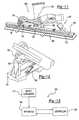
- FIG. 1is a perspective view of an apparatus having an illustrative portable extruder shown mounted on the end of a robotic arm, depicting use of the apparatus to apply extruded materials to parts on an off-line basis according to one aspect of the present invention
- FIG. 2is a sectional view of the portable extruder, taking along the line 2 — 2 in FIG. 1 ;
- FIG. 3is an operational diagrammatic view of the portable extruder shown in FIG. 1 ;
- FIG. 4is a view of the portable extruder of FIG. 1 , but shown in relationship to an assembly line for manufacturing automobiles;
- FIG. 5is an enlarged, perspective view of a portion of a vehicle body and the extruder shown in FIG. 4 ;
- FIG. 6is a cross-sectional view taken along the line 6 — 6 in FIG. 5 ;
- FIGS. 7 a and 7 bare views similar to FIG. 6 but showing a roof panel having been installed, and depicting the position of the extruded sealant bead respectively before and after expansion thereof;
- FIG. 8is a fragmentary, cross-sectional view of an alternate form of a nozzle for use with the extruder of FIG. 1 ;
- FIG. 9is a perspective view of an extruder according to the present invention, depicting an alternate form of a material supply system
- FIG. 10is an enlarged, cross-sectional view of the batch hopper and supply feed tube of the system shown in FIG. 9 , immediately after a batch has been dispensed;
- FIG. 11is a perspective view of an alternate form of the extruder of the present invention, shown in relationship to a conveyor line;
- FIG. 12is a fragmentary rear view of the extruder of FIG. 11 .
- FIG. 13is a block diagram of an automated system for tracking materials.
- FIG. 14is an overhead view of a system and apparatus for dispensing flowable materials onto panels of automotive vehicles.
- FIG. 15illustrates an exemplary movement system according to an aspect of the present invention.
- the present inventioninvolves applying flowable material to various components of articles of manufacture such as automotive vehicles.
- the description of this inventionfirst discusses the potential flowable materials that can be applied according to the methods and using the apparatuses of the invention. Thereafter, the methods and apparatuses that may be used for applying the flowable materials are discussed. Lastly, the components of the articles of manufacture that receive the flowable materials and the manner in which the flowable materials are applied are discussed.
- the flowable materials of the present inventioncan be chosen from a variety of different materials.
- the flowable materialsmay be conventional, but may be applied according to novel methods or using novel apparatuses or both.
- the flowable materialsmay be conventional or known, however, the component to which the flowable materials are applied may be novel.
- the flowable materialsthemselves may be novel.
- the discussion belowis meant to introduce the flowable materials generally according to their chemical makeup and in terms of properties exhibited by the flowable materials, for assisting a person of skill in art in choosing a material, which typically needs to be selected or tailored for a specific desired application.
- the flowable materialsmay be heat activated.
- a preferred heat activated materialis an expandable or other flowable polymeric formulation or composition, and preferably one that is activated to foam, flow or otherwise change states when exposed to the heating operation of a typical automotive painting operation such as during a primer or paint drying step.
- a particularly preferred materialis an active polymer formulated in pellet form with each pellet typically 1-20 mm in diameter and generally, but not necessarily, configured in a geometric or polygonal shape, such as a sphere, to facilitate the flow of such pellets through an applicator such as an extruder.
- One preferred materialis formed of an olefinic polymer-based foam, and more particularly an ethylene based polymer.
- the polymeric foammay be based on ethylene copolymers or terpolymers that may possess an alpha-olefin.
- the polymeris composed of two or three different monomers, i.e., small molecules with high chemical reactivity that are capable of linking up with similar molecules.
- particularly preferred polymersinclude ethylene vinyl acetate, EPDM, or a mixture thereof.
- other examples of preferred foam formulation that are commercially availableinclude polymer-based material commercially available from L&L Products, Inc.
- L-2105L- -2100, L-7005 or L-2018
- L-7100L-7101, L-7102, L-7700, L-2410, L-2411, L-2412, L-4201, L-4141, etc.
- Such materialsmay exhibit properties including sound absorption, vibration absorption, sealing ability, corrosion resistance and the like.
- the materialmay also be a heat-activated epoxy-based resin having foamable characteristics upon activation through the use of heat typically encountered in an e-coat or other automotive paint oven operation. As the expandable material is heated, it expands, cross-links, and structurally bonds to adjacent surfaces.
- An example of a preferred formulationis an epoxy-based material that may include polymer modifies such as an ethylene copolymer or terpolymer that is commercially available from L&L Products, Inc. of Romeo, Mich., under the designations that include L-5204, L-5206, L-5207, L-5208, L-5222 or combinations thereof.
- Such materialsmay exhibit properties including relatively high strength and stiffness, promote adhesion, rigidity, and impart other valuable physical and chemical characteristics and properties.
- the present inventionmay utilize a foamable material formulated to assist in the reduction of vibration and noise after activation.
- reinforced and vibrationally damped componentscan have increased stiffness which will reduce natural frequencies, that resonate through the automotive chassis thereby reducing transmission, blocking or absorbing noise through the use of the conjunctive acoustic product.
- the stiffness and rigidity of the components of a vehicleBy increasing the stiffness and rigidity of the components of a vehicle, the amplitude and frequency of the overall noise, vibration or both that occurs from the operation of the vehicle and is transmitted through the vehicle can be reduced.
- the present inventioncould comprise the use of a combination of an acoustically damping material and a structurally reinforcing expandable material along different portions or zones of the member depending upon the requirements of the desired application.
- Use of acoustic expandable materials in conjunction with structural materialmay provide additional structural improvement but primarily would be incorporated to improve NVH characteristics.
- One such foampreferably includes a polymeric base material, such as an ethylene-based polymer which, when compounded with appropriate ingredients (typically a blowing and curing agent), expands and cures in a reliable and predicable manner upon the application of heat or the occurrence of a particular ambient condition.
- a polymeric base materialsuch as an ethylene-based polymer which, when compounded with appropriate ingredients (typically a blowing and curing agent), expands and cures in a reliable and predicable manner upon the application of heat or the occurrence of a particular ambient condition.
- the foamis usually initially processed as a flowable thermoplastic material before curing. It will cross-link upon curing, which makes the material resistant of further flow or change of final shape.
- the flowable materialcan be formed of other materials (e.g., foams regarded in the art as structural foams) provided that the material selected is heat-activated or otherwise activated by an ambient condition (e.g. moisture, pressure, time or the like) and cures in a predictable and reliable manner under appropriate conditions for the selected application.
- foamsregarded in the art as structural foams
- an ambient conditione.g. moisture, pressure, time or the like
- cures in a predictable and reliable manner under appropriate conditions for the selected applicatione.g. moisture, pressure, time or the like.
- One such materialis the polymeric based resin disclosed in commonly owned, U.S. patent application Ser. No. 09/268,810 (filed Mar. 8, 1999) now U.S. Pat. No. 6,131,897, the teachings of which are incorporated herein by reference.
- Some other possible materialsinclude, but are not limited to, polyolefin materials, copolymers and terpolymers with at least one monomer type an alpha-olefin, phenol/formaldehyde materials, phenoxy materials, and polyurethane. See also, U.S. Pat. Nos. 5,266,133; 5,766,719; 5,755,486; 5,575,526; 5,932,680; and WO 00/27920 (PCT/US99/24795) (all of which are expressly incorporated by reference).
- suitable melt flow materialsinclude, without limitation, formulations found in a commonly owned co-pending applications for a Paintable Seal System filed Aug. 7, 2000, and a Paintable Material filed Aug.
- the resulting materialIn general, some desired characteristics of the resulting material include relatively low glass transition point, and good corrosion resistance properties in this manner, the material does not generally interfere with the materials systems employed by automobile manufacturers. Moreover, it will withstand the processing conditions typically encountered in the manufacture of a vehicle, such as the e-coat priming, cleaning and degreasing and other coating processes, as well as the painting operations encountered in final vehicle assembly.
- a consideration involved with the selection and formulation of the materialis the temperature at which a material reaction or expansion, and possibly curing, will take place.
- the materialis extruded onto the intrusion device by a supplier and then shipped to the vehicle manufacturer as an integrated product. More typically, the material becomes reactive at higher processing temperatures, such as those encountered in an automobile assembly plant, when the material is processed along with the vehicle components at elevated temperatures or at higher applied energy levels, e.g., during e-coat preparation steps and other paint cycles.
- temperatures encountered in an automobile e-coat operationmay be in the range of about 145° C. to about 210° C. (about 300° F. to 400° F.)
- primer, filler and paint shop applicationsare commonly about 100° C. (about 200° F.) or higher.
- the materialis thus operative throughout these ranges. If needed, blowing agent activators can be incorporated into the composition to cause expansion at different temperatures outside the above ranges.
- suitable expandable flowable materialshave a range of volumetric expansion from approximately 0 to over 2000 percent.
- the level of expansion of the vibration reduction material 20may be increased to as high as 1500 percent or more in certain embodiments, the material may be hyper-expandable materials that expand more than 1500 percent and preferably over about 2000 percent.
- the materialmay be expandable to a degree (or otherwise situated on a surface) so that individual nodes remain separated from one another upon expansion, or they may contact one another (either leaving interstitial spaces or not).
- the materialmay be provided in an encapsulated or partially encapsulated form, which may comprise a pellet, which includes an expandable foamable material, encapsulated or partially encapsulated in an adhesive shell.
- an encapsulated or partially encapsulated formwhich may comprise a pellet, which includes an expandable foamable material, encapsulated or partially encapsulated in an adhesive shell.
- the flowable materialmay include a melt-flowable material such as that disclosed in U.S. Pat. No. 6,030,701 (expressly incorporated by reference).
- the flowable materials of the present inventionare formulated such that the materials exhibit desired properties (e.g., tackiness or non-tackiness) at various different processing stages or temperature.
- desired propertiese.g., tackiness or non-tackiness
- flowable materials of the present inventionit is generally desirable for flowable materials of the present invention to activate and flow at temperatures experienced during paint cycles. Prior to activation, however, it is often preferable for the flowable materials to be exhibit solid and substantially non-tacky characteristics at temperatures near room temperature (e.g., between about 5° C. and about 50° C.), while exhibiting characteristics of slight flow and tackiness without activation at mid-level temperatures (e.g., between about 50° C. and about 100° C.).
- these characteristicsallow the materials to be stored, transported and maintained in pellet form without substantial adhesion between the pellets.
- the materialscan be heated to mid-level temperatures to allow the materials to adhere to a substrate during application of the materials as further discussed below.
- a base resin with a narrow molecular weight distributionis preferably included in the material.
- the molecular weight distributionis preferably such that 70% of the polymers in the base resin are within 10,000 atomic mass units (amu) of each other, more preferably 80 percent of the polymers in the base resin are with 5000 amu of each other and even more preferably 90 percent of the polymers are within 1000 amu of each other.
- the base resincomprises about 50 to about 100 weight percent of the material or of the polymeric constituents of the material and more preferably about 60 to about 90 weight percent of the material or of the polymeric constituents of the material.
- the flowable materialsmay be formulated with one or more components, which assist in adhering the materials to a substrate upon application thereto.
- componentsare added to achieve desirable interaction between the flowable materials and contaminants (e.g., oil and lubricants), which may be present upon a surface of a substrate to which the flowable material may be applied.
- the flowable materialincludes one or more solubilizing agents, which assist the flowable material in solubilizing contaminants on a substrate surface.
- solubilizing agentsinclude hydrocarbons (e.g, hydrocarbon process oils), pthalate plasticizers, liquid polyolefins or the like.
- solubilizing agentsare between about 1 and about 30 weight percent of the flowable material, more preferably between about 5 and about 20 weight percent of the flowable material.
- the flowable materialincludes one or more incompatible or low compatibility components, which can displace contaminants upon application of the flowable material to a substrate thereby assisting in adhesion of the flowable material to the substrate.
- such componentshave relatively low molecular weights (e.g., less than 1000 g/mole) such that the components tend to migrate out the resin system of the flowable material.
- examples of such componentsinclude polybutenes, polybutadienes, various waxes or the like.
- such low compatibility componentsare about 0.1 and about 30 weight percent of the flowable material, more preferably between about 2 and about 15 weight percent of the flowable material.
- the flowable materialincludes one or more polar components, which can aid in adhesion of the flowable material to the substrate.
- polar componentsPreferably, such components have relatively low melting points (e.g., between about 50° C. and about 100° C.). Examples of such components include oxidized or otherwise functionalized waxes, epoxy resins or combinations thereof.
- such polar componentsare about 1 and about 30 weight percent of the flowable material, more preferably between about 2 and about 15 weight percent of the flowable material.
- the flowable materialincludes one or more components such as waxes that are modified with an adhesion promoter such as an acid anhydride group.
- an adhesion promotersuch as an acid anhydride group.
- such modified componentsare about 1 and about 30 weight percent of the flowable material, more preferably between about 5 and about 20 weight percent of the flowable material.
- the flowable materialincludes a two-component system wherein a first component interacts with a second component to increase tack of the flowable material during application.
- a first componentinteracts with a second component to increase tack of the flowable material during application.
- pellets of a relatively lower molecular weight materialmay be combined with pellets of a compatible higher molecular weight base polymer, which, upon mixing and elevation to a mid-range temperature, increase tack due to the compatibility of the two types of pellets.
- a small amount of pellets of one materialmay be combined with pellets formed of a second material wherein the first material has reactive functionality that is activated upon mixing with the second material for promoting adhesion.
- the apparatusgenerally includes a lightweight, portable material applicator generally indicated by the numeral 20 .
- the applicator for the present inventionmay be an extruder, pressure applicator such as hydraulic, electric or pneumatic applicators or another suitable applicator.
- the applicator 20is operated on an off-line basis to apply extrusions at appropriate locations on parts that may be stationary or moving, such as to the illustrated roof panels 34 which are mounted on jigs 36 supported on individual tables 38 .
- the extruder 20is powered by a suitable motor 72 (such as a hydraulic motor), which is coupled with a drive mechanism, such as one including a pair of hydraulic lines 42 to a hydraulic pump 44 and related reservoir tank of hydraulic fluid 46 .
- the flowable materialsmay be supplied to the applicator according to various protocols.
- the flowable materialsmay be pumped to the applicator in a flowable state. They may be conveyed by a mechanical conveyor. They may be advanced by a screw. They my be advanced by a piston. Other approaches are also possible.
- Materialsmay be fed to the applicator as a solid and the applicator may process the materials (e.g., with heat, a solvent, a reactant or a combination thereof) to form flowable materials.
- various ingredientsmay be fed to the applicator at various locations.
- an extrudermay have one or a plurality of inlets for receiving various ingredients that are introduced and mixed within the extruder.
- the materialmay be supplied from nearly any suitable container such as a bin or other container, and the material may be supplied in many forms such as pellets, granules, particles or the like.
- suitable pellet shapesinclude cylinders, polyhedron, egg-shaped, oblong trapezoids, rings, cubes, spheres, hemispheres, polyhedrons, prisms, pyramids or other geometric or irregular shapes.
- the form in which the material is suppliedwill typically depend upon the nature of the material being supplied.
- the pelletsinclude very few, if any, sharp edges.
- edges of the pelletsare typically defined by adjoining surfaces of the pellets and the sharpness of those edges is typically defined by the angle at which the surfaces are disposed relative to each other (i.e., the sharper the edge, the smaller or more acute the angle).
- the surfaces forming edges on the pelletsare disposed at greater than about 70°, more preferably greater than about 90° and even more preferably greater than about 110°.
- the pelletsare substantially free of edges, and include only curved sufaces, flat surfaces or both.
- FIG. 3shows a supply bin 52 mounted upon a table 54 which tilts about a pivot point 56 in response to elevation by a pneumatic cylinder 58 .
- a vacuum pump 48draws the solid pellets of material from the supply bin 52 through a draw tube 50 to a point elevated above the applicator 20 .
- the pelletsare then gravity fed through the feed tube 40 into an inlet tube 74 ( FIG. 2 ) of the applicator 20 .
- a hydraulic motor 72provides a large amount of torque and possesses a fast response curve, thus allowing the extrusion to be started and stopped very quickly. This control characteristic is advantageous especially in connection with extruding flowable materials in applications having strict tolerance limits.
- a preferred screw bearing assemblytherefore comprises at least two thrust bearings (or the like) acting in opposite directions. It is contemplated that the present invention also incorporates a process for the use of repeatable and predictable amounts of materials so that the extruder essentially functions as a quasi volumetric pump which can tightly control the rotation angles of the screw.
- a closed-loop servo-control systemcan be used to achieve, control, and operate the position of the screw and may comprise an hydraulic system (which may further include a servo valve) or an electric servomotor. It is contemplated that the hydraulic system is desirable in applications where weight is a prime factor while for stationary systems, the electric system may be the prime choice.
- an optional air blower 47is mounted on the arm 30 of robot 20 delivers air through line 45 to an electrically heated manifold 68 to which there is attached an outlet air nozzle 70 .
- the manifold 68 and a temperature sensor 69 on the end of nozzle 70are connected to the PLC 60 via lines 71 and 73 , respectively.
- the manifold 68is pivotably mounted on a rod 83 which is longitudinally adjustable within a threaded mounting flange 85 which is secured to a hub 110 forming part of the extruder 20 .
- the end of the nozzle 70may be adjusted so as to direct warm air at a desired temperature onto the substrate in close proximity to the point where an extruded bead of material exits an extrusion die 126 and is deposited onto the components.
- the upper end of the cylindrical barrel 86includes a cylindrical flange 101 secured by bolts to a circumferentially extending shoulder of the hub 110 .
- a lateral opening 112 in the sidewall of barrel 86provides pressure relief.
- An inlet opening 90 in the barrel 86allows the introduction of solid material pellets 105 into the interior of the barrel 86 , at the upper end of the feed screw 88 .
- the inlet feed tube 74forms a slight dog leg feed path into the opening 90 which may, depending upon the nature of the pellets 105 and the attitude of the extruder 20 , become jammed somewhat, from time to time, thereby potentially interrupting constant flow to the feed screw 88 .
- a swivel feed tube connectionfor coupling the feed tube 40 to the inlet tube 74 .
- This connectioncomprises an inner, tubular sleeve 92 which extends down into the inlet tube 74 and is secured to the feed tube 40 .
- the inner sleeve 92includes a circumferential flange 107 which rotatably bears upon a mating flange 109 on the upper end of inlet tube 74 .
- Flanges 107 and 109are received within a groove in a collar 84 which is secured to sleeve 92 and has a portion surrounding inlet tube 74 .
- the inner sleeve 92 , collar 84 and feed tube 40rotate independently of the inlet tube 74 .
- the rotational movement of the feed tube 40 , and thus the inner sleeve 92tends to dislodge the pellets so that they flow freely into the inlet opening 90 so as to smoothly feed into the screw 88 .
- a gassuch as air may be blown into the feed tube at regular intervals to assist the flow and dispensation of the pellets and otherwise avoid jams of the pellets.
- the extrudermay be moved and manipulated during the extrusion process through many degrees of motion without stressing or otherwise interfering with proper flow of pellets through the feed tube 40 , since the feed tube 40 rotates freely upon the extruder 20 .
- the flowable materialsmay be heated before entering the applicator, while in the applicator or after leaving the applicator.
- Various heating mechanismsmay be used to heat the flowable material prior to, during, or after the materials are within the applicator. Examples of heating elements include wire wound rubber heaters, mounted heater subassemblies, coil wire heating elements, flexible heating elements, or the like.
- the medial and lower reaches of the barrel 86have mounted therearound band shaped heating elements 114 which are controlled by the PLC 60 .
- the heating bands 114 , 116 and 118surround the barrel 86 and are provided with temperature sensors 113 to provide temperature feed back information to a display (not shown) and the PLC 60 .
- the lower heating band 118can be seen to reach virtually to the end of the barrel 86 , adjacent the extrusion nozzle 120 .
- the heating bands 114 - 118function to melt the pellets 105 into a flowable material which is fed by the screw action of feed screw 88 to an accumulating chamber 122 and thence through a tapered feed passage 124 within nozzle 120 to an extrusion die 126 .
- Extrusion die 126possesses an extrusion opening therein which has a cross-section conforming to the desired shape of the extruded bead.
- the extrusion die 126is threadably received within in the nozzle 120 which in turn is threadably received within a lower threaded opening in barrel 86 , concentric with the central axis of feed screw 88 .
- a pressure sensor 128 secured within nozzle 120delivers signals to the PLC 60 relating to the pressure of the flowable material as it enters the die 126 .
- the PLCoperates the extruder using closed loop control on the rotation of the screw of the extruder.
- the sensortells the PLC how fast the extrudate is being emitted and the screw of the extruder may be rotated slower or faster to realize a proper rate.
- control over the rate of emission of the extrudatecan be precisely controlled and the extruder can get to the desired speed of emission in a very short period of time (e.g., less than a second).
- the applicatoruses closed loop control based upon a metering system.
- the output of flowable material from the extruderis experimentally related to the positioning angle of the extruder and the rotational speed of the extruder screw.
- the amounts of volumetric flowable material output for different rotational speeds of the extruder screwcan be known to a reasonably high degree of certainty thereby permitting proper volumetric output of flowable material as long as the rotational speed of the extruder screw is commensurate with such output.
- a desired profilemay be input to the PLC for a chosen component.
- the profilerelates the desired amount of flowable material output over time, the desired positing angle of the extruder, or both to the desired rotational speed of the extruder screw for a chosen component.
- the flowable materialis output, data regarding the angle of the extruder and the rotational speed of the extruder screw are monitored via sensors such as the sensor 98 or other devices and the data can be sent to the PLC.
- the PLCcommands the motor to either raise, lower or maintain the amount of torque that the motor is applying to the extruder screw such that the output of flowable material or the rotational speed of the extruder screw closely mirror the desired profile.
- the extruderis used as a metering device. Since the output of flowable material is very closely related to and predictable based upon screw rotational speed.
- excess materialmay be removed from the applicator by directing a gas such as air at the outlet of the applicator.
- excess materialmay be removed manually by wiping the outlet with a cloth or other wiping material. Grinding or polishing steps may also be employed.
- a wipermay be provided comprising a wiping wire 80 held between the ends of two arms 78 which are mounted on the end of a rod 76 .
- the rod 76is slidably adjustable within a holder 77 mounted on the table 38 .
- the robot 22moves the extruder 20 such that the outer end of the die 126 passes across the wire 80 which cuts off the excess material.
- the applicator 20may be programmed to pull the flowable material within the applicator 20 after each application such that excess material is removed.
- the PLCmay be programmed to reverse the turning direction of the extruder screw such that the flowable material is drawn back into the extruder 20 for a short period of time or for a short distance after each application thereby minimizing the excess material on the end of the die 126 after each application.
- FIG. 8depicts, on a larger scale, an alternate form of nozzle arrangement for the extruder 20 , in which a plurality of extrusion dies 128 , 130 and 132 are provided.
- the multiple dies 128 - 132may be positioned in the nozzle body 120 a at any desired position or angle, relative to each other, and may possess die openings which differ in their characteristics (size, cross-sectional configuration, etc.). This permits on-line extrusion of differently configured beads without the need for changing dies or using multiple extruders.
- the bottom end of the feed passageway 124delivers flowable material to the dies 128 - 132 via distribution channels 140 , 142 and 144 .
- flow of the materialis selectively controlled to the multiple dies 128 - 132 by means of valving, herein illustrated as ball valves 138 which are operated by linkage rods 138 operated by any suitable form of motors or drive mechanisms such as pneumatic cylinders 136 .
- valvingherein illustrated as ball valves 138 which are operated by linkage rods 138 operated by any suitable form of motors or drive mechanisms such as pneumatic cylinders 136 .
- the apparatus for applying flowable materialsmay be configured for coextruding a plurality of materials (e.g., plastic combinations, metal and plastic combinations, or otherwise).
- a plurality of materialse.g., plastic combinations, metal and plastic combinations, or otherwise.
- more than one diemay be secured to a single applicator or a single die may have more than one opening for emitting separate beads of materials.
- an automotive suppliermay desire to apply a flowable material to a substrate or component at its own facility that is geographically remote from an assembly plant (e.g., an original equipment automotive vehicle assembly line). Thereafter, the component or substrate is typically shipped or otherwise transported to an automotive assembly plant where it is assembled to a vehicle preferably prior to painting of the vehicle.
- FIGS. 4 , 5 and 6depict the extruder 20 adapted for use in an in-line extrusion application for automated assembly of vehicles on a production line.
- Vehicle bodies 146 on a moving production line 154pass by a sealant application station comprising the previously described extruder 20 mounted on the end of a robot 22 .
- the extruder 20Under programmed control of the PLC 60 ( FIG. 3 ) the extruder 20 automatically extrudes a bead 152 of material into a channel 150 formed in the roof surface 148 of each vehicle 146 .
- a precisely configured bead of sealantmay be introduced at the proper location within the channel 150 around the entire periphery of the roof surface 148 , while the vehicle 146 moves down the assembly line.
- apparatuses according to the present inventionmay be configured to place flowable materials upon components of vehicles within very tight tolerances.
- flowable materialsmay be placed within at least one centimeter of their intended location, more preferably within three millimeters of their intended location and even more preferably within one millimeter of their intended location.
- sealant bead 152it can be important for the sealant bead 152 to exit from the extruder 20 at the proper temperature, with proper flow characteristics and with a desired cross-sectional configuration for the sealant bead 152 to properly perform its function.
- material characteristicsare particularly important in various applications, as for example where sealant material is used which later expands after curing or after application of heat, to fill voids (e.g., cavities, gaps, seams or the like).
- Such applicationsmay be applied to automotive vehicles components such as bulkheads, instrument panels, wheel wells, floor pans, door beams, hem flanges, vehicle beltline applications, door sills, rockers, decklids, hoods, etc.
- these componentsmay be formed of metal stampings, molded plastic, extruded plastic, machined or cast metal or the like.
- FIG. 7 adepicts the roof surface 148 immediately after a roof panel 154 has been installed in overlying relationship on the vehicle 146 ; a slight gap forming a void is present between the roof panel 154 and roof surface 148 .
- FIG. 7 bshows the relationship of these components after the bead of sealant has been expanded through curing and/or the application of heat to fill the void between the body parts.
- the control overflow characteristics of the sealant materialis achieved in a very precise manner, for several reasons.
- the use of a hydraulic motor 72results in the provision of a very high level of torque to the feed screw 88 , yet the weight of the hydraulic motor 72 is not so great as to preclude mounting the extruder 20 on a robot arm.
- the sensor 98precisely senses the rotation of the feed screw 88 , and thus provides immediate feedback information which allows the PLC 60 to control the hydraulic motor 72 accordingly.
- the heating bands 114 - 118 , along with temperature sensors 113envelop the sealant material to define separately controllable heating zones and control the final temperature quite precisely as the material exits the extrusion die 126 .
- the exact flow rate of sealant material exiting the die 126is further controlled as result of the provision of the pressure sensor 128 which provides feedback information to the PLC 60 relative to the pressure of the sealant material immediately before it is extruded, which in turn is directly related to flow rate or as a result of the sensor 98 monitoring rotational speed of the extruder screw, which can also be related to flow rate.
- the unique rotatable connection of the feed tube 40 to the extruder 20also assures constant, controllable flow rate in that temporary interruption or diminution of material feed is eliminated.
- the provision of a flow of precisely directed hot air emanating from the heat nozzle 70allows the substrate to be pre-heated, thereby better conditioning the extruded material to absorb oils and the like from the substrate.
- alternate forms for feeding solid pellets of a sealant material to the extruder 20may be provided.
- batch hopper 156may be mounted on the extruder 20 to supply material pellets, rather than the flexible feed tube 40 discussed earlier.
- the batch hopper 156gravity feeds pellets through an elbow tube 166 which is connected with the inlet tube 74 .
- the size of the batch hopper 156accommodates a single “batch” which is sufficient to apply sealant to a given part or for a specific job.
- the robot 22swings the extruder 20 to a loading position, in which the hopper 156 is positioned beneath a material dispenser 158 , with a discharge tube 160 of the dispenser 158 extending down into the interior of the hopper 156 , as best seen in FIG. 10.
- a motor member 162which may be electrical, hydraulic or pneumatic, controls a discharge valve diagrammatically indicated by the numeral 164 in order to allow a single batch of material to be dispensed through the discharge tube 160 into the hopper 156 .
- the robot 22lowers the extruder 20 into clearing relationship to the dispenser 158 and discharge tube 160 .
- the applicatormay be continuously located below the supply of pellets (e.g., wherein the applicator is relatively stationary) such that the supply of beads or pellets can be continually replenished and the beads can continuously flow to the applicator under gravitational forces.
- dissimilar pelletsmay be fed to an extruder to form a flowable material as a blend of materials.
- one materialmay be introduced in pellet or other form into a first opening in the extruder and a second material may be introduced in pellet or other form into a second opening in the extruder.
- a flowable materialmay be formed that includes layers of different materials that are “candy-striped” along the length of the flowable material when the material is applied to a component.
- the openings through which the pellets of different material enter the applicatorare generally opposite each other to form the layers of flowable material.
- various materialssuch as more highly reactive material may be combined with other materials later in the process of forming the desired flowable material to prevent undesired or premature reaction between such materials.
- FIGS. 11 and 12depict an alternate form of the extruder of the present invention, generally indicated by the numeral 180 .
- the extruder 180is similar or identical to the previously described extruder in terms of its component parts; only those parts that may be different than those previously described will be discussed here.
- the extruder 180is mounted for limited movement about two orthogonal axes, at a stationery position along an assembly line which includes a conveyor 168 .
- Conveyor 168moves parts such as the metal channel part 172 along a path guided by transversely spaced, stationary feed guides 170 .
- Feed guides 170precisely control the traverse positioning of the part 172 as it passes by the extruder 180 .
- the extruder 180is pivotably mounted on a pair of spaced apart mounting flanges 186 which are secured to a base 192 .
- a pair of forwardly extending arms 190have one end connected to the structure supporting the extruder 180 , and the other end connected to the output shaft of a hydraulic or pneumatic cylinder 188 which functions to raise or lower the extrusion die 176 .
- Counter weightsmay be mounted on the opposite end of the extruder 180 , as required, to achieve proper balance.
- a batch type hopper 178is provided on the extruder 180 to supply pellets or other solid forms of sealant material.
- a hot air sourcee.g., a blower 182 is mounted up-stream from the extrusion die 176 to apply hot air at a desired temperature via the exit nozzle 184 to preheat the part 172 .
- Other heating mechanismssuch as those identified elsewhere herein may also be employed as desired.
- a guide shoe 174 mounted on a guide arm 194 of the extruder 180is adapted to be received within a groove or channel in the part 172 and functions to pivot the extruder 180 about an axis (e.g., a vertical axis), depending upon the traverse position of the channel or groove within the part 172 .
- the shoe 174acts as a camming guide to precisely move and locate the extrusion die 176 relative to the part channel so that the bead of sealant material is dispensed in precise registration within the groove or channel within the part 172 .
- a bar code system 300may be employed.
- portions of an apparatus 302 for supplying flowable materialsmay include bar code scanner.
- the bar code scannersare positioned upon portions of the apparatus 302 that initially receive flowable materials in pellet form prior to processing.
- Exemplary positions for such scannersmay include positions adjacent supply containers 314 such as the bin 52 of FIG. 3 or positions adjacent the batch hopper 178 of FIG. 11 such that the scanners may scan bar codes affixed to the supply containers preferably prior to introduction of materials from the containers 314 to the apparatus 302 .
- the scannersare in signaling communication with a controller 320 (e.g., a computer or other controller) for signaling to the controller 320 the identification or bar code of any supply container 314 that has been placed in position to feed material to the apparatus 302 .
- the controller 320may be programmed with data to determine if the desired supply container 314 having the desired bar code has been positioned to supply the apparatus 302 at the desired time. Thus, if an undesired supply container 314 is positioned to supply material, the controller 320 may signal a response.
- a variety of responsesmay be signaled such as an audible response (e.g., a horn, bell, tone, or siren), a visual response (e.g., a light, such as a flashing light), a combination thereof or another response.
- the controller 320is in communication with the apparatus 302 such that the apparatus may be partially or fully shut down if any undesired material is going to be fed to the apparatus 302 .
- the flowable materials disclosed hereinmay be applied to a surface of a wide variety of components for several articles of manufacture.
- a componentmay be one of several parts of an article of manufacture or a component may be the only part of an article of manufacture.
- the surface to which the flowable material is appliedmay be substantially planar or may be contoured (e.g., curved, angled, arced and the like).
- the surfaceat least partially defines a channel for receiving the flowable materials.
- the surfaceis part of a component of an automotive vehicle.
- the surfacemay be part of any stamped metal component that is assembled within an automotive vehicle structure.
- the surface of the componentmay be cleansed of impurities such as dirt, grime, oil and the like prior to application of the flowable material, the surface may be heated prior to application of the flowable material, the surface may be coated prior to application of the flowable material or a combination of treatments may be performed on the surface.
- impuritiessuch as dirt, grime, oil and the like
- the surfacemay be heated prior to application of the flowable material
- the surfacemay be coated prior to application of the flowable material or a combination of treatments may be performed on the surface.
- impuritiesmay preferably be removed by exposing the surfaces of compounds to energy from an energy source.
- the surfaceis cleansed by exposing the surface to a plasma formed by a plasma generator.
- Plasma generatorsmay generate various plasmas such as a non-thermal or non-equilibrium plasma or a dielectric barrier plasma.
- the surfaceis exposed to the plasma and the plasma provides energy to any impurities located upon the surface.
- the impuritiesare burned off, evaporated or otherwise removed from the surface such that the surface is more suitable for receiving a flowable material.
- a laser or flash lampmay be used to expose a surface of a component to energy beams or energy pulses.
- the laser or flash lamprequires relatively low energy input to produce energy pulses with relatively high peak power.
- One exemplary laseris a Q-switched NdYag laser that can deliver relatively fast high peak power pulses (e.g., pulses having pulse times of around 10 nanoseconds, pulse powers up to and greater than 10 Watts and pulse wavelength of around 1 micron).
- the exemplary lasercan deliver such pulses with a frequency of about 100 Hz. It is believed that the energy pulses form an unstable plasma on the surface of a component, wherein the plasma in an effort to stabilize generates a shockwave effect that blasts away grease, grime and other impurities from the surface of the component.
- the surface of the componentmay be exposed to light from one or more heat lamps.
- the heat lampsemit light toward the surface of the component wherein the light has a wavelength typical of visible or near infrared light (e.g. around 750 nanometers).
- the flash lampsremove impurities from the surfaces of the components and the heat lamps may also heat the surfaces of the components.
- the heat lampsdirect light toward a surface of a stamped metal component of an automotive vehicle thereby evaporating the impurities (e.g., particularly oil) that is often present upon the stamped metal components.
- the surface of the componentsare exposed to the light from the heat lamps for a period of time that heats the surfaces to a temperature substantially equivalent to the temperature at which flowable material is being applied to the component.
- a primermay be coated upon a surface of a component before a flowable material is applied to the surface.
- the primermay be manually or automatically applied to the surface of a component.
- the primeris applied after cleansing the surface of the component.
- the primerassists flowable materials in adhering to the surfaces of components.
- the apparatus for applying the flowable materialsmay be configured with a first nozzle or opening for applying primer and a second opening (e.g., of a die) for applying flowable materials after the primer has been applied.
- the flowable materialsmay be applied to the surface of a component without pre-heating the component due to the type of flowable material being applied.
- the surfaceis pre-treated or cleansed using one of the methods (e.g., plasma, primer, laser and the like) discussed above.
- the flowable material or pellet or even a plurality of pellets (in an uncured state)is generally dry or relatively free of tack to the touch at room temperature.
- the componentsmay be moved relative to an applicator such that the melt flowable materials emitted from the applicator are properly positioned on the surfaces of the components.
- the componentmay be placed or mounted upon surface or other supports and movement systems such as conveyor belts, robots, robot arms, carousels, turntables and the like for moving the components beneath an applicator.
- An example of a turntable or carousel 600is illustrated in FIG. 15 .
- These systemsmay move the components radially about an axis, along a contoured path, along one or more lines or otherwise.
- these systemsmay move independently or dependently relative to a robot arm, which may move the applicator and these systems may have a same or different controller from the robot arm.
- the componentsmay be moved relative to the flowable materials either faster, slower or at substantially the same rate that the flowable materials are emitted from an applicator.
- the flowable materialsmay be applied to the components along almost any predetermined path.
- the flowable materialsmay be applied to the components in a variety of shapes.
- the flowable materialsare applied as beads through a die and assume the shape of an opening of the die. By using different dies, different shapes may be achieved.
- flowable materialsmay be applied as a single continuous bead or as a plurality of spaced beads.
- the beadsalso may vary in size as desired. For example, cross-sectional areas of the beads may range from about 1 mm 2 up to about 1000 mm 2 and more preferably from about 10 mm 2 to about 500 mm 2 and still more preferably from about 100 mm 2 to about 300 mm 2 .
- the flowable materialsmay be desirable for the flowable materials to maintain certain chemical or physical properties, referred to herein as pre-assembly properties, for relatively large intervals of time between application of the flowable materials to a component and assembly of the component to an article of manufacture. After assembly, however, it may be desirable for the flowable materials to exhibit other physical properties referred to herein as post-assembly properties.
- Flowable materialsare provided according to the present invention wherein the materials applied to the components exhibit properties such as non-tackiness and the like, shortly after they are initially applied to the components.
- the flowable materialsmay be applied to the components in a condition suitable for transport (i.e., the components can be placed adjacent or in contact with each other or other components without the flowable materials adhering or otherwise attaching to adjacent components). Thereafter, the flowable materials can be triggered by heat, chemicals or other stimulus to change the chemical or physical properties of the flowable materials during or after the time that the components upon which the flowable materials reside are assembled within an article of manufacture.
- the chemical or physical properties after triggeringmay include adhesivity, expansion and the like.
- the flowable material 20is applied in a viscoelastic state which can easily and uniformly be applied to an exterior surface of the components in a relatively clean manner where it hardens and bonds.
- the materialcools at the ambient temperature found in a manufacturing facility which allows the material to return to its original solid or dry chemical state thereby bonding and adhering the material to the external surface of the component.
- the componentis then integrated into an article of manufacture such as an automotive vehicle for application of heat such as from the e-coat process as well as other paint operation cycles commonly found in an automotive manufacturing facility.
- the materialis allowed to expand, thereby chemically cross-linking the material on the external surfaces of adjacent components of the article of manufacture.
- the flowable materialis a plastic adhesive that is non-tacky below a first temperature of, for example, around 40 degrees Celsius but exhibits tackiness when heated above the first temperature and exhibits an even higher degree of tackiness at a second higher temperature, which is around those temperature exhibited by a typical e-coat process as discussed above.
- the plastic adhesivecan be applied to the components at temperatures between 40 degrees Celsius and 180 degrees Celsius and the adhesive will adhere to the components adequately for the adhesive to be transported but without any high degree of deformation of the flowable material.
- the flowable materialis still substantially in its green or non-activated/non-cured state.
- the adhesivemay be cooled or partially cured to temperatures below around 40 degrees such that the component and the adhesive may be transported without the adhesive adhering to other objects, which it may come into contact with. Then, the component may be assembled within an article of manufacture and the temperature of the adhesive may be elevated to the second temperature so that the component is adhesively secured as a component of the article of manufacture once the adhesive is again cooled or finally cured.
- Such an adhesiveprovides an advantage over other adhesives since it doesn't typically sag, run, wash away or get displaced during processing and handling.
- the flowable materialsmay be applied to metal surfaces of components, coated or uncoated, painted or unpainted, welded or unwelded.
- the flowable materialsare applied to components of automotive vehicles such as door beams, closure panels such as trunk lids or hood lids, roof bows, fuel filler doors, exterior trim, vehicle A-pillars.
- the flowable materialsmay also be applied in an automotive vehicle roof ditch, upon emblems or within a water management trough surrounding the trunk space of a vehicle.
- the flowable materialsmay be applied to suspension components, hangers, brackets and the like for systems such as exhaust systems. Other components include hem flanges, emblems and the like.
- the flowable materialsmay be applied to components in need of dampening, sealing or corrosion protection.
- the materialsmay be applied to fill seal or other occupy various holes or openings within vehicles such as rat holes, space between dissimilar metals, notches and the like. According to preferred embodiments, the material may extend across holes, openings or other gaps without sagging.
- flowable materialsmay be applied to various portions or regions of substantially a whole-body side panel.
- FIG. 14there is illustrated a system 500 for applying flowable materials to whole-body side panels 504 for automotive vehicles.
- the system 500includes a robot 508 for moving and otherwise manipulating the side panels 504 .
- the system 500also includes an apparatus 512 for applying melt-flowable materials.
- the apparatus 512includes an applicator (e.g., an extruder) as discussed above.
- the robot 508has the capability to support the panels 504 and move the panels 504 relative to the apparatus.
- the robot 508moves at least one of the panels 504 below the applicator of the apparatus 512 according to a predetermined pattern.
- the applicatorpreferably emit flowable materials at predetermined times such that the flowable materials are applied to the panel 504 at predetermined locations.
Landscapes
- Engineering & Computer Science (AREA)
- Mechanical Engineering (AREA)
- Extrusion Moulding Of Plastics Or The Like (AREA)
- Application Of Or Painting With Fluid Materials (AREA)
- Molding Of Porous Articles (AREA)
- Coating Apparatus (AREA)
- Processing Of Solid Wastes (AREA)
Abstract
Description
Claims (22)
Priority Applications (11)
| Application Number | Priority Date | Filing Date | Title |
|---|---|---|---|
| US10/342,025US7043815B2 (en) | 2002-01-25 | 2003-01-14 | Method for applying flowable materials |
| CA002417018ACA2417018A1 (en) | 2002-01-25 | 2003-01-22 | Method and apparatus for applying flowable materials |
| PT03075228TPT1331080E (en) | 2002-01-25 | 2003-01-23 | Method for applying foamable flowable materials to vehicle components |
| EP03075228AEP1331080B1 (en) | 2002-01-25 | 2003-01-23 | Method for applying foamable flowable materials to vehicle components |
| SI200332124TSI1331080T1 (en) | 2002-01-25 | 2003-01-23 | Method for applying foamable flowable materials to vehicle components |
| ES03075228TES2378660T3 (en) | 2002-01-25 | 2003-01-23 | Procedure for applying foamable materials capable of flowing to vehicle components |
| AT03075228TATE541690T1 (en) | 2002-01-25 | 2003-01-23 | METHOD FOR APPLYING FOAMABLE LIQUID MATERIALS TO VEHICLE COMPONENTS |
| JP2003016277AJP4664577B2 (en) | 2002-01-25 | 2003-01-24 | Method and apparatus for applying flowable material |
| MXPA03000762AMXPA03000762A (en) | 2002-01-25 | 2003-01-24 | Method and apparatus for applying flowable materials. |
| US11/339,431US7467452B2 (en) | 2002-01-25 | 2006-01-25 | Method for applying flowable materials |
| JP2010255299AJP2011056510A (en) | 2002-01-25 | 2010-11-15 | Method for applying flowable material |
Applications Claiming Priority (2)
| Application Number | Priority Date | Filing Date | Title |
|---|---|---|---|
| US35196702P | 2002-01-25 | 2002-01-25 | |
| US10/342,025US7043815B2 (en) | 2002-01-25 | 2003-01-14 | Method for applying flowable materials |
Related Child Applications (1)
| Application Number | Title | Priority Date | Filing Date |
|---|---|---|---|
| US11/339,431ContinuationUS7467452B2 (en) | 2002-01-25 | 2006-01-25 | Method for applying flowable materials |
Publications (2)
| Publication Number | Publication Date |
|---|---|
| US20030140671A1 US20030140671A1 (en) | 2003-07-31 |
| US7043815B2true US7043815B2 (en) | 2006-05-16 |
Family
ID=26992779
Family Applications (2)
| Application Number | Title | Priority Date | Filing Date |
|---|---|---|---|
| US10/342,025Expired - LifetimeUS7043815B2 (en) | 2002-01-25 | 2003-01-14 | Method for applying flowable materials |
| US11/339,431Expired - LifetimeUS7467452B2 (en) | 2002-01-25 | 2006-01-25 | Method for applying flowable materials |
Family Applications After (1)
| Application Number | Title | Priority Date | Filing Date |
|---|---|---|---|
| US11/339,431Expired - LifetimeUS7467452B2 (en) | 2002-01-25 | 2006-01-25 | Method for applying flowable materials |
Country Status (9)
| Country | Link |
|---|---|
| US (2) | US7043815B2 (en) |
| EP (1) | EP1331080B1 (en) |
| JP (2) | JP4664577B2 (en) |
| AT (1) | ATE541690T1 (en) |
| CA (1) | CA2417018A1 (en) |
| ES (1) | ES2378660T3 (en) |
| MX (1) | MXPA03000762A (en) |
| PT (1) | PT1331080E (en) |
| SI (1) | SI1331080T1 (en) |
Cited By (20)
| Publication number | Priority date | Publication date | Assignee | Title |
|---|---|---|---|---|
| US20040262853A1 (en)* | 2003-06-26 | 2004-12-30 | L&L Products, Inc. | Fastenable member for sealing, baffling or reinforcing and method of forming same |
| US20060127584A1 (en)* | 2002-01-25 | 2006-06-15 | L&L Products, Inc. | Method and apparatus for applying flowable materials |
| US20060193609A1 (en)* | 2003-03-24 | 2006-08-31 | Lennart Rantzen | Apparatus for joining roof covering materials |
| US20080226866A1 (en)* | 2007-03-15 | 2008-09-18 | Zephyros, Inc. | Sealant material |
| US8381403B2 (en) | 2005-05-25 | 2013-02-26 | Zephyros, Inc. | Baffle for an automotive vehicle and method of use therefor |
| US20130092324A1 (en)* | 2011-03-04 | 2013-04-18 | Siegfried Dietz | Joining Surface Treatment Device and Method |
| US20140102628A1 (en)* | 2012-10-12 | 2014-04-17 | GM Global Technology Operations LLC | Methods, systems, components, and compositions for simultaneously treating a substrate and adhering or applying a bonding agent thereto |
| US9259867B2 (en) | 2010-05-21 | 2016-02-16 | Zephyros, Inc. | Method and device for application of structural materials |
| US20160346804A1 (en)* | 2015-05-29 | 2016-12-01 | Hyundai Motor Company | Primer device and application system applying the device |
| US9616574B2 (en) | 2013-08-20 | 2017-04-11 | Honda Motor Co., Ltd. | Plasma-sealant wobble paddle |
| US9879162B2 (en) | 2013-02-22 | 2018-01-30 | Zephyros, Inc. | Method for formation and application of adhesive |
| US9987785B2 (en) | 2012-04-26 | 2018-06-05 | Zephyros, Inc. | Applying flowable materials to synthetic substrates |
| US10106205B2 (en) | 2016-07-21 | 2018-10-23 | Zephyros, Inc. | Reinforcement structure |
| US10173727B2 (en) | 2016-07-28 | 2019-01-08 | Zephyros, Inc. | Multiple stage deformation reinforcement structure for impact absorption |
| US10696033B2 (en)* | 2014-06-23 | 2020-06-30 | Exel Industries | Apparatus for applying protective films |
| USD938887S1 (en) | 2018-06-21 | 2021-12-21 | Zephyros, Inc. | Sealing device |
| EP3844053B1 (en) | 2018-08-31 | 2023-06-07 | Sika Technology AG | Device for reinforcing, sealing or damping of a structural element |
| EP3844051B1 (en) | 2018-08-31 | 2023-06-07 | Sika Technology AG | System for insulation of a structural element |
| DE102023102269B3 (en) | 2023-01-31 | 2024-06-06 | Audi Aktiengesellschaft | Drying device and method for drying a dip-painted body for a motor vehicle |
| US20240317510A1 (en)* | 2021-02-11 | 2024-09-26 | Sika Technology Ag | Method for attaching insulating elements to structural elements |
Families Citing this family (90)
| Publication number | Priority date | Publication date | Assignee | Title |
|---|---|---|---|---|
| US6634698B2 (en)* | 2000-08-14 | 2003-10-21 | L&L Products, Inc. | Vibrational reduction system for automotive vehicles |
| GB2375328A (en) | 2001-05-08 | 2002-11-13 | L & L Products | Reinforcing element for hollow structural member |
| US6793274B2 (en) | 2001-11-14 | 2004-09-21 | L&L Products, Inc. | Automotive rail/frame energy management system |
| US7318873B2 (en)* | 2002-03-29 | 2008-01-15 | Zephyros, Inc. | Structurally reinforced members |
| US7169344B2 (en)* | 2002-04-26 | 2007-01-30 | L&L Products, Inc. | Method of reinforcing at least a portion of a structure |
| US7077460B2 (en) | 2002-04-30 | 2006-07-18 | L&L Products, Inc. | Reinforcement system utilizing a hollow carrier |
| GB0211775D0 (en) | 2002-05-23 | 2002-07-03 | L & L Products Inc | Multi segment parts |
| US20040011282A1 (en)* | 2002-07-18 | 2004-01-22 | Myers Robert D. | System and method for manufacturing physical barriers |
| US6920693B2 (en) | 2002-07-24 | 2005-07-26 | L&L Products, Inc. | Dynamic self-adjusting assembly for sealing, baffling or structural reinforcement |
| US20040018353A1 (en)* | 2002-07-25 | 2004-01-29 | L&L Products, Inc. | Composite metal foam damping/reinforcement structure |
| US7004536B2 (en)* | 2002-07-29 | 2006-02-28 | L&L Products, Inc. | Attachment system and method of forming same |
| US6923499B2 (en)* | 2002-08-06 | 2005-08-02 | L & L Products | Multiple material assembly for noise reduction |
| US6811864B2 (en)* | 2002-08-13 | 2004-11-02 | L&L Products, Inc. | Tacky base material with powder thereon |
| US6883858B2 (en)* | 2002-09-10 | 2005-04-26 | L & L Products, Inc. | Structural reinforcement member and method of use therefor |
| US7105112B2 (en) | 2002-11-05 | 2006-09-12 | L&L Products, Inc. | Lightweight member for reinforcing, sealing or baffling |
| GB0300159D0 (en)* | 2003-01-06 | 2003-02-05 | L & L Products Inc | Improved reinforcing members |
| US7313865B2 (en)* | 2003-01-28 | 2008-01-01 | Zephyros, Inc. | Process of forming a baffling, sealing or reinforcement member with thermoset carrier member |
| US7111899B2 (en)* | 2003-04-23 | 2006-09-26 | L & L Products, Inc. | Structural reinforcement member and method of use therefor |
| US7125461B2 (en)* | 2003-05-07 | 2006-10-24 | L & L Products, Inc. | Activatable material for sealing, baffling or reinforcing and method of forming same |
| GB2401349A (en) | 2003-05-08 | 2004-11-10 | L & L Products | Reinforcement for a vehicle panel |
| US7041193B2 (en)* | 2003-05-14 | 2006-05-09 | L & L Products, Inc. | Method of adhering members and an assembly formed thereby |
| US7479245B2 (en) | 2003-06-26 | 2009-01-20 | Zephyros, Inc. | Process for applying a material to a member |
| US7784186B2 (en)* | 2003-06-26 | 2010-08-31 | Zephyros, Inc. | Method of forming a fastenable member for sealing, baffling or reinforcing |
| US7469459B2 (en) | 2003-09-18 | 2008-12-30 | Zephyros, Inc. | System and method employing a porous container for sealing, baffling or reinforcing |
| US20050095359A1 (en)* | 2003-10-31 | 2005-05-05 | Nordson Corporation | Hot melt adhesive system and method using machine readable information |
| US7180027B2 (en)* | 2004-03-31 | 2007-02-20 | L & L Products, Inc. | Method of applying activatable material to a member |
| GB2415658A (en)* | 2004-06-21 | 2006-01-04 | L & L Products Inc | An overmoulding process |
| US7392929B1 (en) | 2004-07-26 | 2008-07-01 | Zephyros, Inc. | Weldable synthetic material |
| US20050012280A1 (en)* | 2004-08-13 | 2005-01-20 | L&L Products, Inc. | Sealing member, sealing method and system formed therewith |
| US7374219B2 (en) | 2004-09-22 | 2008-05-20 | Zephyros, Inc. | Structural reinforcement member and method of use therefor |
| EP1693178A1 (en)* | 2005-02-22 | 2006-08-23 | Advanced Elastomer Systems, L.P. | Tubular Free-Shaped Article |
| US7503620B2 (en) | 2005-05-12 | 2009-03-17 | Zephyros, Inc. | Structural reinforcement member and method of use therefor |
| EP1745859A1 (en)* | 2005-07-20 | 2007-01-24 | Vlaamse Instelling Voor Technologisch Onderzoek (Vito) | A method and apparatus for applying a coating on a substrate |
| US20070022624A1 (en)* | 2005-08-01 | 2007-02-01 | Sino Golf Manufacturing Co., Ltd. | Paint-drying system and method |
| US7926179B2 (en) | 2005-08-04 | 2011-04-19 | Zephyros, Inc. | Reinforcements, baffles and seals with malleable carriers |
| US7484946B2 (en)* | 2005-08-19 | 2009-02-03 | Zephyros, Inc. | Method and assembly for locating material within a structure |
| GB0600901D0 (en) | 2006-01-17 | 2006-02-22 | L & L Products Inc | Improvements in or relating to reinforcement of hollow profiles |
| US8236128B2 (en)* | 2006-10-26 | 2012-08-07 | Zephyros, Inc. | Adhesive materials, adhesive parts formed therewith and their uses |
| EP2138241B1 (en)* | 2007-04-10 | 2014-05-28 | Musashi Engineering, Inc. | Method and device for discharging viscous liquid material |
| GB2455292A (en)* | 2007-12-03 | 2009-06-10 | Zephyros Inc | Improvements in or relating to the production of joints |
| EP2242634B1 (en) | 2008-01-16 | 2020-03-25 | Sika Technology AG | System and method for producing an extruded expandable barrier |
| GB0806434D0 (en) | 2008-04-09 | 2008-05-14 | Zephyros Inc | Improvements in or relating to structural adhesives |
| US8216499B2 (en)* | 2008-12-09 | 2012-07-10 | The Boeing Company | Extrusion of adhesives for composite structures |
| US20100178433A1 (en)* | 2009-01-14 | 2010-07-15 | Gm Global Technology Operations, Inc. | Method and apparatus for applying bonding adhesive |
| US8322771B2 (en)* | 2009-10-05 | 2012-12-04 | Honda Motor Co., Ltd. | Connection between roof panel and side panel |
| JP2013521163A (en) | 2010-03-04 | 2013-06-10 | ゼフィロス インコーポレイテッド | Structural composite laminate |
| DE102010032744A1 (en)* | 2010-07-29 | 2012-02-02 | Kiekert Ag | Method and device for applying a seal to a surface of a device housing for a motor vehicle |
| GB201016530D0 (en) | 2010-09-30 | 2010-11-17 | Zephyros Inc | Improvements in or relating to adhesives |
| EP2481775A1 (en)* | 2011-01-28 | 2012-08-01 | LANXESS Deutschland GmbH | Use of moulding materials |
| GB201102035D0 (en)* | 2011-02-04 | 2011-03-23 | Zephyros Inc | Improvements in or relating to extrusion |
| JP5777904B2 (en)* | 2011-02-25 | 2015-09-09 | 中部電力株式会社 | Sealing agent coating method and coating apparatus |
| JP5372991B2 (en)* | 2011-04-28 | 2013-12-18 | 株式会社日立製作所 | Method and apparatus for treating urethane foam |
| GB201119287D0 (en) | 2011-11-08 | 2011-12-21 | Zephyros Inc | Improvements in or relating to structrual adhesives |
| US10371468B2 (en) | 2011-11-30 | 2019-08-06 | Palo Alto Research Center Incorporated | Co-extruded microchannel heat pipes |
| US9120190B2 (en) | 2011-11-30 | 2015-09-01 | Palo Alto Research Center Incorporated | Co-extruded microchannel heat pipes |
| GB201201943D0 (en) | 2012-02-03 | 2012-03-21 | Zephyros Inc | Improvements in or relating to the production of joints |
| US8875653B2 (en)* | 2012-02-10 | 2014-11-04 | Palo Alto Research Center Incorporated | Micro-extrusion printhead with offset orifices for generating gridlines on non-square substrates |
| US20130310507A1 (en) | 2012-05-18 | 2013-11-21 | 3D Systems, Inc. | Adhesive for 3D Printing |
| WO2014060205A1 (en)* | 2012-10-15 | 2014-04-24 | Sika Technology Ag | Method for producing a foam element and portable foam extruder |
| MX377708B (en)* | 2012-12-19 | 2025-03-11 | Henkel Ag & Co Kgaa | Method for the sound damping and/or sound insulation of components |
| GB201300483D0 (en) | 2013-01-11 | 2013-02-27 | Zephyros Inc | Extrusion of bands of material |
| US10537913B2 (en)* | 2013-04-29 | 2020-01-21 | Hewlett-Packard Development Company, L.P. | Selective slot coating |
| CN105637007A (en) | 2013-07-26 | 2016-06-01 | 泽费罗斯股份有限公司 | Thermosetting adhesive films including a fibrous carrier |
| US9604676B2 (en) | 2013-08-15 | 2017-03-28 | Ford Global Technologies, Llc | Method of providing a corrosion barrier between dissimilar metals with an epoxy insulator |
| EP3063053B1 (en) | 2013-10-31 | 2020-02-12 | Sika Technology AG | Baffle or reinforcement element for sealing and/or reinforcing a cavity and method for producing such a baffle or reinforcement element |
| FR3018464B1 (en)* | 2014-03-11 | 2017-10-13 | Euro Cryospace | METHOD AND DEVICE FOR LASER SURFACE TREATMENT OF A METAL STRUCTURE FOR THE MANUFACTURE OF A CRYOGENIC RESERVOIR |
| US9583337B2 (en)* | 2014-03-26 | 2017-02-28 | Ultratech, Inc. | Oxygen radical enhanced atomic-layer deposition using ozone plasma |
| GB201417985D0 (en) | 2014-10-10 | 2014-11-26 | Zephyros Inc | Improvements in or relating to structural adhesives |
| GB201420627D0 (en)* | 2014-11-20 | 2015-01-07 | Zephyros Inc | Application of adhesives |
| EP3227089A1 (en)* | 2014-12-01 | 2017-10-11 | SABIC Global Technologies B.V. | Nozzle tool changing for material extrusion additive manufacturing |
| DE102015008953B4 (en)* | 2015-07-10 | 2021-10-07 | Audi Ag | Process for pretreating thermoplastic components for structural bonding - and device for processing a surface |
| CN108355932B (en)* | 2016-01-08 | 2020-12-22 | 浙江黎盛新材料科技有限公司 | A metal plate coating curing device |
| WO2017198675A1 (en) | 2016-05-19 | 2017-11-23 | Zephyros, Inc. | Hot melt applicable structural adhesives |
| ITUA20164378A1 (en)* | 2016-06-15 | 2017-12-15 | Gienne Plast S R L | APPARATUS AND METHOD |
| CN106111446A (en)* | 2016-07-27 | 2016-11-16 | 太仓澄天机械有限公司 | A kind of semi-automatic adhesive dispensing device |
| CN109641624A (en)* | 2016-08-05 | 2019-04-16 | 泽菲罗斯有限公司 | Cavity sealing system for motor vehicles |
| RU2719973C1 (en)* | 2017-03-30 | 2020-04-23 | Мазда Мотор Корпорейшн | Coating application device and coating application method |
| CN110753655B (en) | 2017-06-22 | 2022-10-28 | Sika技术股份公司 | Reinforcing element, system of reinforced structural elements and method for reinforcing structural elements |
| ES2896004T3 (en) | 2017-06-22 | 2022-02-23 | Sika Tech Ag | Connection of body elements in motor vehicles |
| CN113474091B (en)* | 2019-02-25 | 2023-06-06 | 3M创新有限公司 | Filament adhesive dispenser system |
| US11472087B2 (en)* | 2019-03-25 | 2022-10-18 | The Boeing Company | Composite radius filler manufacturing methods and related systems |
| DE102019218896A1 (en)* | 2019-12-04 | 2021-06-10 | Guangdong Yizumi Precision Machinery Co., Ltd. | Process for the production of a 2-component component as well as an injection molding machine and extruder |
| JP7731356B2 (en)* | 2019-12-20 | 2025-08-29 | スリーエム イノベイティブ プロパティズ カンパニー | How to Apply Filament Adhesive |
| EP3932572A1 (en)* | 2020-07-03 | 2022-01-05 | Ewald Dörken Ag | Method for treating surfaces |
| CN111940173B (en)* | 2020-08-12 | 2021-07-23 | 石家庄铁路职业技术学院 | Online bridge outer surface coating device |
| CN112827754B (en)* | 2021-01-07 | 2022-02-15 | 中国空气动力研究与发展中心超高速空气动力研究所 | Automatic packaging equipment for MEMS friction resistance sensor based on visual positioning technology |
| CN113333253B (en)* | 2021-02-26 | 2022-12-02 | 机械工业第九设计研究院股份有限公司 | Double-color car roof flame polishing process |
| ES2945335A1 (en)* | 2021-12-30 | 2023-06-30 | Focke Meler Gluing Solutions S A | FEEDING HOPPER OF PELLET PRODUCT FOR ADHESIVE MELTING EQUIPMENT (Machine-translation by Google Translate, not legally binding) |
| CN119836449A (en) | 2022-09-05 | 2025-04-15 | 泽费罗斯股份有限公司 | Curable polymer composition with improved wash-off resistance |
| KR102754653B1 (en)* | 2024-10-30 | 2025-01-22 | 주식회사 동네형 | Method for Manufacturing Extruded Benches or Tables using Upcycled Materials |
Citations (73)
| Publication number | Priority date | Publication date | Assignee | Title |
|---|---|---|---|---|
| US2972553A (en)* | 1957-04-01 | 1961-02-21 | Gen Plastics Corp | Nylon coating method |
| US3101277A (en)* | 1963-08-20 | Metal surface such as aluminum | ||
| US3372053A (en)* | 1963-07-22 | 1968-03-05 | Anchor Hocking Glass Corp | Coating process |
| US4083384A (en) | 1976-03-04 | 1978-04-11 | Airrigation Engineering Company, Inc. | Method and apparatus for injecting foam into a pipeline, including an inflatable plug |
| US4399174A (en) | 1981-03-16 | 1983-08-16 | Nissan Motor Company, Limited | Reinforcing material |
| US4610836A (en) | 1983-09-12 | 1986-09-09 | General Motors Corporation | Method of reinforcing a structural member |
| US4813690A (en) | 1987-11-24 | 1989-03-21 | L & L Products, Inc. | Sealing member |
| WO1989006595A1 (en) | 1986-09-29 | 1989-07-27 | Sekisui Kagaku Kogyo Kabushiki Kaisha | A method for the production of composite pipes |
| US4853270A (en) | 1988-06-27 | 1989-08-01 | Essex Specialty Products, Inc. | Knee blocker for automotive application |
| US4922596A (en) | 1987-09-18 | 1990-05-08 | Essex Composite Systems | Method of manufacturing a lightweight composite automotive door beam |
| US4923902A (en) | 1988-03-10 | 1990-05-08 | Essex Composite Systems | Process and compositions for reinforcing structural members |
| US4978562A (en) | 1990-02-05 | 1990-12-18 | Mpa Diversified Products, Inc. | Composite tubular door beam reinforced with a syntactic foam core localized at the mid-span of the tube |
| US5124186A (en) | 1990-02-05 | 1992-06-23 | Mpa Diversified Products Co. | Composite tubular door beam reinforced with a reacted core localized at the mid-span of the tube |
| US5141093A (en)* | 1991-04-17 | 1992-08-25 | Progressive Tool & Industries Co. | Automotive body panel handling apparatus |
| US5266133A (en) | 1993-02-17 | 1993-11-30 | Sika Corporation | Dry expansible sealant and baffle composition and product |
| EP0588182A2 (en) | 1992-09-18 | 1994-03-23 | M. Faist GmbH & Co. KG | Foam sound damping or insulating element manufacturing method thereof and its use |
| US5358397A (en) | 1993-05-10 | 1994-10-25 | L&L Products, Inc. | Apparatus for extruding flowable materials |
| US5382395A (en)* | 1993-05-14 | 1995-01-17 | Admiral Equipment Co. | Profile extrusion apparatus and method for extruding a profile |
| US5382397A (en) | 1988-03-30 | 1995-01-17 | Nordson Corporation | Method of forming closed cell foam seals for automotive body seams |
| US5544930A (en) | 1994-10-05 | 1996-08-13 | Chrysler Corporation | Floating end structural reinforcement for a vehicle door |
| EP0775721A1 (en) | 1995-01-21 | 1997-05-28 | Mitsubishi Jidosha Kogyo Kabushiki Kaisha | Heat-expandable filling reinforcement and closed-section structural-member structure reinforced with said reinforcement |
| US5749992A (en)* | 1993-03-25 | 1998-05-12 | Ab Volvo | Process for producing an adhesive bond in a folder joint |
| US5755486A (en) | 1995-05-23 | 1998-05-26 | Novamax Technologies Holdings, Inc. | Composite structural reinforcement member |
| US5766719A (en) | 1994-03-14 | 1998-06-16 | Magna Exterior Systems Gmbh | Composite material |
| US5807588A (en)* | 1995-07-27 | 1998-09-15 | Toyota Jidosha Kabushiki Kaisha | Extrusion molding apparatus and an apparatus for controlling the same |
| US5817268A (en)* | 1996-01-31 | 1998-10-06 | Tokai Kogyo Kabushiki Kaisha | Method of integrally molding a weather strip on a panel edge |
| US5846465A (en)* | 1995-03-16 | 1998-12-08 | Asahi Glass Company, Ltd. | Method for preparing a plate member for a window with a resinous frame |
| US5878784A (en) | 1994-05-11 | 1999-03-09 | British Gas Plc | Pipe blocking technique |
| DE29904705U1 (en) | 1998-12-23 | 1999-06-17 | Mannesmann AG, 40213 Düsseldorf | Device for producing a profile part |
| WO1999036243A1 (en) | 1998-01-14 | 1999-07-22 | Compsys, Inc. | Composite spring and damper units and method of making same |
| US5932680A (en) | 1993-11-16 | 1999-08-03 | Henkel Kommanditgesellschaft Auf Aktien | Moisture-curing polyurethane hot-melt adhesive |
| WO1999048746A1 (en) | 1998-03-20 | 1999-09-30 | Möller Plast GmbH | Hollow profile with inner reinforcement and method for producing said hollow profile |
| US6030701A (en) | 1993-04-15 | 2000-02-29 | 3M Innovative Properties Company | Melt-flowable materials and method of sealing surfaces |
| WO2000010802A1 (en) | 1998-08-20 | 2000-03-02 | H.R. Technologies, Inc. | Adhesive composition, article, and processes of manufacture |
| US6053210A (en) | 1993-12-21 | 2000-04-25 | Vinidex Tubemakers Pty. Limited | Expandable plug and control method |
| WO2000027920A1 (en) | 1998-11-05 | 2000-05-18 | Sika Corporation | Sound deadening and structural reinforcement compositions and methods of using the same |
| US6093358A (en) | 1998-01-27 | 2000-07-25 | Lear Corporation | Method of making an expandable gap filling product |
| WO2000046461A1 (en) | 1999-02-02 | 2000-08-10 | Sika Ag, Vormals Kaspar Winkler & Co. | Method for producing a flat strip |
| US6103341A (en) | 1997-12-08 | 2000-08-15 | L&L Products | Self-sealing partition |
| US6135541A (en) | 1998-08-12 | 2000-10-24 | Honda Giken Kogyo Kabushiki Kaisha | Automobile door to provide high-quality closing sound |
| US6203859B1 (en)* | 1993-09-24 | 2001-03-20 | Optimum Air Corporation | Method of drying substrates and use thereof |
| US6254488B1 (en) | 1999-07-13 | 2001-07-03 | Daimlerchrysler Corporation | Hydroformed drive shaft and method of making the same |
| US6253819B1 (en) | 1998-04-28 | 2001-07-03 | Denovus Llc | Method and apparatus for die cutting and making laminate articles |
| US6270600B1 (en) | 1996-07-03 | 2001-08-07 | Henkel Corporation | Reinforced channel-shaped structural member methods |
| US20010042353A1 (en) | 2000-04-26 | 2001-11-22 | Ken Honda | Devices and methods for reinforcing hollow structural members |
| US6321793B1 (en) | 2000-06-12 | 2001-11-27 | L&L Products | Bladder system for reinforcing a portion of a longitudinal structure |
| EP1182087A2 (en) | 2000-08-25 | 2002-02-27 | Nissan Motor Co., Ltd. | Sound absorbing-insulating structure for vehicles |
| US6389775B1 (en) | 1997-12-02 | 2002-05-21 | Sika Ag, Vormals Kasper Winkler & Co. | Reinforcement element for load-carrying or load-transferring structural parts and method for fixing said reinforcement element to the surface of a structural part |
| US20020066254A1 (en) | 1995-09-04 | 2002-06-06 | Alfred Ebbinghaus | Reinforced formed part, process for its production and its use |
| US6406078B1 (en) | 1994-05-19 | 2002-06-18 | Henkel Corporation | Composite laminate automotive structures |
| US6419305B1 (en) | 2000-09-29 | 2002-07-16 | L&L Products, Inc. | Automotive pillar reinforcement system |
| WO2002055923A2 (en) | 2001-01-16 | 2002-07-18 | Daimlerchrysler Ag | Structural element reinforced with metal foam |
| US6444713B1 (en) | 1997-05-21 | 2002-09-03 | Denovus Llc | Foaming compositions and methods for making and using the compositions |
| US6458439B1 (en)* | 1996-05-17 | 2002-10-01 | The Valspar Corporation | Extrusion coating compositions and method |
| US6467834B1 (en) | 2000-02-11 | 2002-10-22 | L&L Products | Structural reinforcement system for automotive vehicles |
| US6471285B1 (en) | 2000-09-29 | 2002-10-29 | L&L Products, Inc. | Hydroform structural reinforcement system |
| US6471774B1 (en)* | 1999-05-07 | 2002-10-29 | Designetics | Automated priming station |
| US20020164450A1 (en) | 2001-04-30 | 2002-11-07 | Lupini Michael Allen | Reinforcement for expandable compositions and methods for using the reinforcement |
| US6482486B1 (en) | 2000-03-14 | 2002-11-19 | L&L Products | Heat activated reinforcing sleeve |
| US6561571B1 (en) | 2000-09-29 | 2003-05-13 | L&L Products, Inc. | Structurally enhanced attachment of a reinforcing member |
| US6607831B2 (en) | 2000-12-28 | 2003-08-19 | 3M Innovative Properties Company | Multi-layer article |
| US6634698B2 (en) | 2000-08-14 | 2003-10-21 | L&L Products, Inc. | Vibrational reduction system for automotive vehicles |
| US6660086B1 (en)* | 2000-03-06 | 2003-12-09 | Innovative Coatings, Inc. | Method and apparatus for extruding a coating upon a substrate surface |
| US6668457B1 (en) | 1999-12-10 | 2003-12-30 | L&L Products, Inc. | Heat-activated structural foam reinforced hydroform |
| US6675467B2 (en)* | 1999-07-16 | 2004-01-13 | Honda Giken Kogyo Kabushiki Kaisha | Automotive manufacturing system |
| US20040011282A1 (en) | 2002-07-18 | 2004-01-22 | Myers Robert D. | System and method for manufacturing physical barriers |
| EP1428744A1 (en) | 2002-12-13 | 2004-06-16 | Henkel KGaA | A method and apparatus for structurally reinforcing a member by insertion of the reinforcement |
| US6752451B2 (en) | 2001-03-27 | 2004-06-22 | Nippon Steel Corporation | Strengthening member for automobile |
| EP1134314B1 (en) | 2000-03-16 | 2004-09-08 | Hexcel Composites | Intermediate composite product, manufacturing of such a product and usage as a molding material |
| WO2004078451A1 (en) | 2003-03-05 | 2004-09-16 | Dow Global Technologies Inc. | Structural reinforcement article and process for prepareation thereof |
| US20040195817A1 (en) | 2001-11-30 | 2004-10-07 | 3M Innovative Properties Company | Method of hydroforming articles and the articles formed thereby |
| US6811864B2 (en) | 2002-08-13 | 2004-11-02 | L&L Products, Inc. | Tacky base material with powder thereon |
| US6820923B1 (en) | 2000-08-03 | 2004-11-23 | L&L Products | Sound absorption system for automotive vehicles |
Family Cites Families (38)
| Publication number | Priority date | Publication date | Assignee | Title |
|---|---|---|---|---|
| FR1518739A (en) | 1967-01-06 | 1968-03-29 | Folding camping caravan | |
| FR2334489A1 (en)* | 1975-12-09 | 1977-07-08 | Fontaine Jacques | CONTINUOUS FEEDING DEVICE FOR AN EXTRUDER FOR SHEATH MOUNTED ON A ROTATING BASE AROUND A VERTICAL AXIS |
| GB2105064A (en)* | 1981-08-27 | 1983-03-16 | Durapipe Ltd | Moulding or extrusion of synthetic plastics products |
| US4448736A (en)* | 1982-05-24 | 1984-05-15 | Standard Oil Company (Indiana) | Continuous in-line melt flow rate control system |
| US4437046A (en)* | 1982-06-18 | 1984-03-13 | Crompton & Knowles Corporation | Extrusion drive control system |
| JPS61144327A (en)* | 1984-12-19 | 1986-07-02 | Japan Steel Works Ltd:The | Back pressure control device for resin extruder |
| DE3627537A1 (en)* | 1986-08-13 | 1988-02-18 | Ver Glaswerke Gmbh | GLASS DISC PROVIDED WITH AN ELASTIC SEALING PROFILE, IN PARTICULAR CAR GLASS DISC |
| JPH02100672U (en)* | 1989-01-23 | 1990-08-10 | ||
| DE4123588A1 (en)* | 1991-07-17 | 1993-01-21 | Ver Glaswerke Gmbh | METHOD AND DEVICE FOR PRODUCING A VEHICLE WINDOW |
| DE4315469A1 (en)* | 1993-05-10 | 1994-11-17 | Ver Glaswerke Gmbh | Method and device for extruding a calibrated profile strand from a thermoplastic polymer onto objects |
| DE4326650A1 (en)* | 1993-08-09 | 1995-02-16 | Ver Glaswerke Gmbh | Method and devices for producing a glass pane provided with a molded-on frame made of a polymer |
| GB2285277B (en)* | 1993-12-24 | 1998-02-25 | Toyoda Machine Works Ltd | Method and apparatus for attaching a molding |
| JP3627379B2 (en)* | 1995-06-13 | 2005-03-09 | 旭硝子株式会社 | Method for manufacturing plate-like body with resin frame |
| DE69611575T2 (en)* | 1995-06-13 | 2001-08-23 | Asahi Glass Co. Ltd., Tokio/Tokyo | Method of making a plate with a plastic frame |
| JPH091631A (en) | 1995-06-16 | 1997-01-07 | Kobe Steel Ltd | Sheet width adjusting device for roller head extruder |
| GB9512294D0 (en)* | 1995-06-16 | 1995-08-16 | Pilkington Glass Ltd | Improvements in or relating to vehicle windows |
| US5894403A (en)* | 1997-05-01 | 1999-04-13 | Wilson Greatbatch Ltd. | Ultrasonically coated substrate for use in a capacitor |
| JP2000017467A (en)* | 1998-07-07 | 2000-01-18 | Aisan Ind Co Ltd | Cast iron parts subjected to rust-preventive treatment and surface treatment method therefor |
| US6103152A (en) | 1998-07-31 | 2000-08-15 | 3M Innovative Properties Co. | Articles that include a polymer foam and method for preparing same |
| US6419078B1 (en)* | 1998-10-06 | 2002-07-16 | Frost Links, Inc. | Lubricating device for conveyor systems |
| JP2000157903A (en)* | 1998-11-26 | 2000-06-13 | Fuji Xerox Co Ltd | Coating device with flowable material |
| DE19938328C2 (en)* | 1999-08-12 | 2003-10-30 | Daimler Chrysler Ag | Method and device for the automated application of an adhesive bead |
| JP2001065958A (en)* | 1999-08-23 | 2001-03-16 | Osaka Gas Co Ltd | Air conditioner and operation method thereof |
| US20050016671A1 (en) | 2001-03-05 | 2005-01-27 | Sharp Terrance M. | Robotic tape applicator and method |
| US7043815B2 (en) | 2002-01-25 | 2006-05-16 | L & L Products, Inc. | Method for applying flowable materials |
| US7169344B2 (en) | 2002-04-26 | 2007-01-30 | L&L Products, Inc. | Method of reinforcing at least a portion of a structure |
| US7077460B2 (en) | 2002-04-30 | 2006-07-18 | L&L Products, Inc. | Reinforcement system utilizing a hollow carrier |
| US20040018353A1 (en) | 2002-07-25 | 2004-01-29 | L&L Products, Inc. | Composite metal foam damping/reinforcement structure |
| US7004536B2 (en) | 2002-07-29 | 2006-02-28 | L&L Products, Inc. | Attachment system and method of forming same |
| US20040044623A1 (en)* | 2002-08-28 | 2004-03-04 | Wake Susan L. | Billing system for wireless device activity |
| WO2004067304A2 (en) | 2003-01-17 | 2004-08-12 | Dow Global Technologies, Inc. | Method for making vehicle door panels |
| US7041193B2 (en) | 2003-05-14 | 2006-05-09 | L & L Products, Inc. | Method of adhering members and an assembly formed thereby |
| US7784186B2 (en) | 2003-06-26 | 2010-08-31 | Zephyros, Inc. | Method of forming a fastenable member for sealing, baffling or reinforcing |
| US7479245B2 (en) | 2003-06-26 | 2009-01-20 | Zephyros, Inc. | Process for applying a material to a member |
| US7249415B2 (en) | 2003-06-26 | 2007-07-31 | Zephyros, Inc. | Method of forming members for sealing or baffling |
| EP1568749A1 (en) | 2004-02-25 | 2005-08-31 | Sika Technology AG | Two-component adhesive for producing semi-finished products and sandwich composites |
| US7180027B2 (en) | 2004-03-31 | 2007-02-20 | L & L Products, Inc. | Method of applying activatable material to a member |
| GB2415162A (en) | 2004-06-15 | 2005-12-21 | L & L Products Inc | Improvements in or relating to laminar mouldings |
- 2003
- 2003-01-14USUS10/342,025patent/US7043815B2/ennot_activeExpired - Lifetime
- 2003-01-22CACA002417018Apatent/CA2417018A1/ennot_activeAbandoned
- 2003-01-23EPEP03075228Apatent/EP1331080B1/ennot_activeExpired - Lifetime
- 2003-01-23SISI200332124Tpatent/SI1331080T1/enunknown
- 2003-01-23ESES03075228Tpatent/ES2378660T3/ennot_activeExpired - Lifetime
- 2003-01-23PTPT03075228Tpatent/PT1331080E/enunknown
- 2003-01-23ATAT03075228Tpatent/ATE541690T1/enactive
- 2003-01-24MXMXPA03000762Apatent/MXPA03000762A/enactiveIP Right Grant
- 2003-01-24JPJP2003016277Apatent/JP4664577B2/ennot_activeExpired - Fee Related
- 2006
- 2006-01-25USUS11/339,431patent/US7467452B2/ennot_activeExpired - Lifetime
- 2010
- 2010-11-15JPJP2010255299Apatent/JP2011056510A/enactivePending
Patent Citations (77)
| Publication number | Priority date | Publication date | Assignee | Title |
|---|---|---|---|---|
| US3101277A (en)* | 1963-08-20 | Metal surface such as aluminum | ||
| US2972553A (en)* | 1957-04-01 | 1961-02-21 | Gen Plastics Corp | Nylon coating method |
| US3372053A (en)* | 1963-07-22 | 1968-03-05 | Anchor Hocking Glass Corp | Coating process |
| US4083384A (en) | 1976-03-04 | 1978-04-11 | Airrigation Engineering Company, Inc. | Method and apparatus for injecting foam into a pipeline, including an inflatable plug |
| US4399174A (en) | 1981-03-16 | 1983-08-16 | Nissan Motor Company, Limited | Reinforcing material |
| US4610836A (en) | 1983-09-12 | 1986-09-09 | General Motors Corporation | Method of reinforcing a structural member |
| WO1989006595A1 (en) | 1986-09-29 | 1989-07-27 | Sekisui Kagaku Kogyo Kabushiki Kaisha | A method for the production of composite pipes |
| US4922596A (en) | 1987-09-18 | 1990-05-08 | Essex Composite Systems | Method of manufacturing a lightweight composite automotive door beam |
| US4813690A (en) | 1987-11-24 | 1989-03-21 | L & L Products, Inc. | Sealing member |
| US4923902A (en) | 1988-03-10 | 1990-05-08 | Essex Composite Systems | Process and compositions for reinforcing structural members |
| US5382397A (en) | 1988-03-30 | 1995-01-17 | Nordson Corporation | Method of forming closed cell foam seals for automotive body seams |
| US4853270A (en) | 1988-06-27 | 1989-08-01 | Essex Specialty Products, Inc. | Knee blocker for automotive application |
| US4978562A (en) | 1990-02-05 | 1990-12-18 | Mpa Diversified Products, Inc. | Composite tubular door beam reinforced with a syntactic foam core localized at the mid-span of the tube |
| US5124186A (en) | 1990-02-05 | 1992-06-23 | Mpa Diversified Products Co. | Composite tubular door beam reinforced with a reacted core localized at the mid-span of the tube |
| US5141093A (en)* | 1991-04-17 | 1992-08-25 | Progressive Tool & Industries Co. | Automotive body panel handling apparatus |
| EP0588182A2 (en) | 1992-09-18 | 1994-03-23 | M. Faist GmbH & Co. KG | Foam sound damping or insulating element manufacturing method thereof and its use |
| US5266133A (en) | 1993-02-17 | 1993-11-30 | Sika Corporation | Dry expansible sealant and baffle composition and product |
| US5749992A (en)* | 1993-03-25 | 1998-05-12 | Ab Volvo | Process for producing an adhesive bond in a folder joint |
| US6030701A (en) | 1993-04-15 | 2000-02-29 | 3M Innovative Properties Company | Melt-flowable materials and method of sealing surfaces |
| US5358397A (en) | 1993-05-10 | 1994-10-25 | L&L Products, Inc. | Apparatus for extruding flowable materials |
| US5382395A (en)* | 1993-05-14 | 1995-01-17 | Admiral Equipment Co. | Profile extrusion apparatus and method for extruding a profile |
| US6203859B1 (en)* | 1993-09-24 | 2001-03-20 | Optimum Air Corporation | Method of drying substrates and use thereof |
| US5932680A (en) | 1993-11-16 | 1999-08-03 | Henkel Kommanditgesellschaft Auf Aktien | Moisture-curing polyurethane hot-melt adhesive |
| US6053210A (en) | 1993-12-21 | 2000-04-25 | Vinidex Tubemakers Pty. Limited | Expandable plug and control method |
| US5766719A (en) | 1994-03-14 | 1998-06-16 | Magna Exterior Systems Gmbh | Composite material |
| US5878784A (en) | 1994-05-11 | 1999-03-09 | British Gas Plc | Pipe blocking technique |
| US6406078B1 (en) | 1994-05-19 | 2002-06-18 | Henkel Corporation | Composite laminate automotive structures |
| US5544930A (en) | 1994-10-05 | 1996-08-13 | Chrysler Corporation | Floating end structural reinforcement for a vehicle door |
| EP0775721A1 (en) | 1995-01-21 | 1997-05-28 | Mitsubishi Jidosha Kogyo Kabushiki Kaisha | Heat-expandable filling reinforcement and closed-section structural-member structure reinforced with said reinforcement |
| US5846465A (en)* | 1995-03-16 | 1998-12-08 | Asahi Glass Company, Ltd. | Method for preparing a plate member for a window with a resinous frame |
| US5755486A (en) | 1995-05-23 | 1998-05-26 | Novamax Technologies Holdings, Inc. | Composite structural reinforcement member |
| US5807588A (en)* | 1995-07-27 | 1998-09-15 | Toyota Jidosha Kabushiki Kaisha | Extrusion molding apparatus and an apparatus for controlling the same |
| US20020066254A1 (en) | 1995-09-04 | 2002-06-06 | Alfred Ebbinghaus | Reinforced formed part, process for its production and its use |
| US5817268A (en)* | 1996-01-31 | 1998-10-06 | Tokai Kogyo Kabushiki Kaisha | Method of integrally molding a weather strip on a panel edge |
| US6458439B1 (en)* | 1996-05-17 | 2002-10-01 | The Valspar Corporation | Extrusion coating compositions and method |
| US6270600B1 (en) | 1996-07-03 | 2001-08-07 | Henkel Corporation | Reinforced channel-shaped structural member methods |
| US6444713B1 (en) | 1997-05-21 | 2002-09-03 | Denovus Llc | Foaming compositions and methods for making and using the compositions |
| US6389775B1 (en) | 1997-12-02 | 2002-05-21 | Sika Ag, Vormals Kasper Winkler & Co. | Reinforcement element for load-carrying or load-transferring structural parts and method for fixing said reinforcement element to the surface of a structural part |
| US6383610B1 (en) | 1997-12-08 | 2002-05-07 | L&L Products, Inc. | Self-sealing partition |
| US6103341A (en) | 1997-12-08 | 2000-08-15 | L&L Products | Self-sealing partition |
| WO1999036243A1 (en) | 1998-01-14 | 1999-07-22 | Compsys, Inc. | Composite spring and damper units and method of making same |
| US6093358A (en) | 1998-01-27 | 2000-07-25 | Lear Corporation | Method of making an expandable gap filling product |
| WO1999048746A1 (en) | 1998-03-20 | 1999-09-30 | Möller Plast GmbH | Hollow profile with inner reinforcement and method for producing said hollow profile |
| US6253819B1 (en) | 1998-04-28 | 2001-07-03 | Denovus Llc | Method and apparatus for die cutting and making laminate articles |
| US6135541A (en) | 1998-08-12 | 2000-10-24 | Honda Giken Kogyo Kabushiki Kaisha | Automobile door to provide high-quality closing sound |
| WO2000010802A1 (en) | 1998-08-20 | 2000-03-02 | H.R. Technologies, Inc. | Adhesive composition, article, and processes of manufacture |
| WO2000027920A1 (en) | 1998-11-05 | 2000-05-18 | Sika Corporation | Sound deadening and structural reinforcement compositions and methods of using the same |
| DE29904705U1 (en) | 1998-12-23 | 1999-06-17 | Mannesmann AG, 40213 Düsseldorf | Device for producing a profile part |
| WO2000038863A1 (en) | 1998-12-23 | 2000-07-06 | Magna Investments S.A. | Method and device for producing a profiled part consisting of metal foam and sheet metal |
| WO2000046461A1 (en) | 1999-02-02 | 2000-08-10 | Sika Ag, Vormals Kaspar Winkler & Co. | Method for producing a flat strip |
| US6471774B1 (en)* | 1999-05-07 | 2002-10-29 | Designetics | Automated priming station |
| US6254488B1 (en) | 1999-07-13 | 2001-07-03 | Daimlerchrysler Corporation | Hydroformed drive shaft and method of making the same |
| US6675467B2 (en)* | 1999-07-16 | 2004-01-13 | Honda Giken Kogyo Kabushiki Kaisha | Automotive manufacturing system |
| US6668457B1 (en) | 1999-12-10 | 2003-12-30 | L&L Products, Inc. | Heat-activated structural foam reinforced hydroform |
| US6467834B1 (en) | 2000-02-11 | 2002-10-22 | L&L Products | Structural reinforcement system for automotive vehicles |
| US6660086B1 (en)* | 2000-03-06 | 2003-12-09 | Innovative Coatings, Inc. | Method and apparatus for extruding a coating upon a substrate surface |
| US6482486B1 (en) | 2000-03-14 | 2002-11-19 | L&L Products | Heat activated reinforcing sleeve |
| EP1134314B1 (en) | 2000-03-16 | 2004-09-08 | Hexcel Composites | Intermediate composite product, manufacturing of such a product and usage as a molding material |
| US20010042353A1 (en) | 2000-04-26 | 2001-11-22 | Ken Honda | Devices and methods for reinforcing hollow structural members |
| US6550847B2 (en) | 2000-04-26 | 2003-04-22 | Neo-Ex Lab, Inc. | Devices and methods for reinforcing hollow structural members |
| US6321793B1 (en) | 2000-06-12 | 2001-11-27 | L&L Products | Bladder system for reinforcing a portion of a longitudinal structure |
| US6820923B1 (en) | 2000-08-03 | 2004-11-23 | L&L Products | Sound absorption system for automotive vehicles |
| US6634698B2 (en) | 2000-08-14 | 2003-10-21 | L&L Products, Inc. | Vibrational reduction system for automotive vehicles |
| EP1182087A2 (en) | 2000-08-25 | 2002-02-27 | Nissan Motor Co., Ltd. | Sound absorbing-insulating structure for vehicles |
| US6471285B1 (en) | 2000-09-29 | 2002-10-29 | L&L Products, Inc. | Hydroform structural reinforcement system |
| US6561571B1 (en) | 2000-09-29 | 2003-05-13 | L&L Products, Inc. | Structurally enhanced attachment of a reinforcing member |
| US6419305B1 (en) | 2000-09-29 | 2002-07-16 | L&L Products, Inc. | Automotive pillar reinforcement system |
| US6607831B2 (en) | 2000-12-28 | 2003-08-19 | 3M Innovative Properties Company | Multi-layer article |
| WO2002055923A2 (en) | 2001-01-16 | 2002-07-18 | Daimlerchrysler Ag | Structural element reinforced with metal foam |
| US6752451B2 (en) | 2001-03-27 | 2004-06-22 | Nippon Steel Corporation | Strengthening member for automobile |
| US20020164450A1 (en) | 2001-04-30 | 2002-11-07 | Lupini Michael Allen | Reinforcement for expandable compositions and methods for using the reinforcement |
| US20040195817A1 (en) | 2001-11-30 | 2004-10-07 | 3M Innovative Properties Company | Method of hydroforming articles and the articles formed thereby |
| US20040011282A1 (en) | 2002-07-18 | 2004-01-22 | Myers Robert D. | System and method for manufacturing physical barriers |
| US6811864B2 (en) | 2002-08-13 | 2004-11-02 | L&L Products, Inc. | Tacky base material with powder thereon |
| EP1428744A1 (en) | 2002-12-13 | 2004-06-16 | Henkel KGaA | A method and apparatus for structurally reinforcing a member by insertion of the reinforcement |
| US20040135058A1 (en) | 2002-12-13 | 2004-07-15 | Joseph Wycech | Method and apparatus for inserting a structural reinforcing member within a portion of an article of manufacture |
| WO2004078451A1 (en) | 2003-03-05 | 2004-09-16 | Dow Global Technologies Inc. | Structural reinforcement article and process for prepareation thereof |
Non-Patent Citations (11)
| Title |
|---|
| Copending U.S. Appl. No 09/939,245 filed Aug. 24, 2001. |
| Copending U.S. Appl. No. 09/459,756 filed Dec. 10, 1999. |
| Copending U.S. Appl. No. 09/631,211 filed Aug. 3, 2000. |
| Copending U.S. Appl. No. 09/676,725 filed Sep. 29, 2000. |
| Copending U.S. Appl. No. 09/858,939 filed May 16, 2001. |
| Copending U.S. Appl. No. 09/923,138 filed Aug. 6, 2001. |
| Copending U.S. Appl. No. 10/216,944 filed Aug. 12, 2002. |
| Copending U.S. Appl. No. 10/217,991 filed Aug. 13, 2002. |
| Copending U.S. Appl. No. 60/399,742 filed Jul. 30, 2002. |
| Copending U.S. Appl. No. 60/413,493 filed Sep. 25, 2002. |
| Copending U.S. Appl. No. 60/415,511 filed Oct. 2, 2002. |
Cited By (49)
| Publication number | Priority date | Publication date | Assignee | Title |
|---|---|---|---|---|
| US20060127584A1 (en)* | 2002-01-25 | 2006-06-15 | L&L Products, Inc. | Method and apparatus for applying flowable materials |
| US7467452B2 (en) | 2002-01-25 | 2008-12-23 | Zephyros, Inc. | Method for applying flowable materials |
| US7305177B2 (en)* | 2003-03-24 | 2007-12-04 | Lennart Rantzen | Apparatus for joining roof covering materials |
| US20060193609A1 (en)* | 2003-03-24 | 2006-08-31 | Lennart Rantzen | Apparatus for joining roof covering materials |
| US20110192015A1 (en)* | 2003-06-26 | 2011-08-11 | Zephyros, Inc. | Fastenable member for sealing, baffling or reinforcing and method of forming same |
| US11390004B2 (en) | 2003-06-26 | 2022-07-19 | Zephyros, Inc. | Fastenable member for sealing, baffling or reinforcing and method of forming same |
| US10328624B2 (en) | 2003-06-26 | 2019-06-25 | Zephyros, Inc. | Method of forming fastenable member for sealing, baffling or reinforcing |
| US9352505B2 (en) | 2003-06-26 | 2016-05-31 | Zephyros, Inc. | Method of forming fastenable member for sealing, baffling or reinforcing |
| US7249415B2 (en)* | 2003-06-26 | 2007-07-31 | Zephyros, Inc. | Method of forming members for sealing or baffling |
| US7941925B2 (en)* | 2003-06-26 | 2011-05-17 | Zephyros, Inc. | Method of forming members for providing sealing or baffling |
| US8931173B2 (en) | 2003-06-26 | 2015-01-13 | Zephyros, Inc. | Method of forming fastenable member for sealing, baffling or reinforcing |
| US20070257515A1 (en)* | 2003-06-26 | 2007-11-08 | Zephyros, Inc. | Fastenable member for sealing, baffling or reinforcing and method of forming same |
| US20040262853A1 (en)* | 2003-06-26 | 2004-12-30 | L&L Products, Inc. | Fastenable member for sealing, baffling or reinforcing and method of forming same |
| US8671573B2 (en)* | 2003-06-26 | 2014-03-18 | Zephyros, Inc. | Method of forming fastenable member for sealing, baffling or reinforcing |
| US8381403B2 (en) | 2005-05-25 | 2013-02-26 | Zephyros, Inc. | Baffle for an automotive vehicle and method of use therefor |
| WO2008112992A2 (en) | 2007-03-15 | 2008-09-18 | Zephyros, Inc. | Sealant material |
| US20080226866A1 (en)* | 2007-03-15 | 2008-09-18 | Zephyros, Inc. | Sealant material |
| US11389994B2 (en) | 2010-05-21 | 2022-07-19 | Zephyros, Inc. | Method and device for application of structural materials |
| US9802342B2 (en) | 2010-05-21 | 2017-10-31 | Zephyros, Inc. | Method and device for application of structural materials |
| US9259867B2 (en) | 2010-05-21 | 2016-02-16 | Zephyros, Inc. | Method and device for application of structural materials |
| US20130092324A1 (en)* | 2011-03-04 | 2013-04-18 | Siegfried Dietz | Joining Surface Treatment Device and Method |
| US8678060B2 (en)* | 2011-03-04 | 2014-03-25 | Fft Edag Produktionssysteme Gmbh & Co. Kg | Joining surface treatment device and method |
| US9987785B2 (en) | 2012-04-26 | 2018-06-05 | Zephyros, Inc. | Applying flowable materials to synthetic substrates |
| US20140102628A1 (en)* | 2012-10-12 | 2014-04-17 | GM Global Technology Operations LLC | Methods, systems, components, and compositions for simultaneously treating a substrate and adhering or applying a bonding agent thereto |
| US9879162B2 (en) | 2013-02-22 | 2018-01-30 | Zephyros, Inc. | Method for formation and application of adhesive |
| US11629275B2 (en) | 2013-02-22 | 2023-04-18 | Zephyros, Inc. | Method for formation and application of adhesive |
| EP4083154A1 (en) | 2013-02-22 | 2022-11-02 | Zephyros Inc. | Method for formation and application of adhesive |
| US10589427B2 (en) | 2013-08-20 | 2020-03-17 | Honda Motor Co., Ltd | Plasma-sealant wobble paddle |
| US9616574B2 (en) | 2013-08-20 | 2017-04-11 | Honda Motor Co., Ltd. | Plasma-sealant wobble paddle |
| US10696033B2 (en)* | 2014-06-23 | 2020-06-30 | Exel Industries | Apparatus for applying protective films |
| US10596587B2 (en) | 2015-05-29 | 2020-03-24 | Hyundai Motor Company | Primer device and application system applying the device |
| US20160346804A1 (en)* | 2015-05-29 | 2016-12-01 | Hyundai Motor Company | Primer device and application system applying the device |
| US9795980B2 (en)* | 2015-05-29 | 2017-10-24 | Hyundai Motor Company | Primer device and application system applying the device |
| US10800462B2 (en) | 2016-07-21 | 2020-10-13 | Zephyros, Inc. | Reinforcement structure |
| US10196097B2 (en) | 2016-07-21 | 2019-02-05 | Zephyros, Inc. | Reinforcement structure |
| US10106205B2 (en) | 2016-07-21 | 2018-10-23 | Zephyros, Inc. | Reinforcement structure |
| US12286158B2 (en) | 2016-07-28 | 2025-04-29 | Zephyros, Inc. | Multiple stage deformation reinforcement structure for impact absorption |
| US10875579B2 (en) | 2016-07-28 | 2020-12-29 | Zephyros, Inc. | Multiple stage deformation reinforcement structure for impact absorption |
| US10183699B2 (en) | 2016-07-28 | 2019-01-22 | Zephyros, Inc. | Multiple stage deformation reinforcement structure for impact absorption |
| US11465686B2 (en) | 2016-07-28 | 2022-10-11 | Zephyros, Inc. | Multiple stage deformation reinforcement structure for impact absorption |
| US10173727B2 (en) | 2016-07-28 | 2019-01-08 | Zephyros, Inc. | Multiple stage deformation reinforcement structure for impact absorption |
| US11565755B2 (en) | 2016-07-28 | 2023-01-31 | Zephyros, Inc. | Multiple stage deformation reinforcement structure for impact absorption |
| USD938887S1 (en) | 2018-06-21 | 2021-12-21 | Zephyros, Inc. | Sealing device |
| EP3844051B1 (en) | 2018-08-31 | 2023-06-07 | Sika Technology AG | System for insulation of a structural element |
| US12246776B2 (en) | 2018-08-31 | 2025-03-11 | Sika Technology Ag | System for insulating a structural element |
| EP3844053B1 (en) | 2018-08-31 | 2023-06-07 | Sika Technology AG | Device for reinforcing, sealing or damping of a structural element |
| US20240317510A1 (en)* | 2021-02-11 | 2024-09-26 | Sika Technology Ag | Method for attaching insulating elements to structural elements |
| DE102023102269B3 (en) | 2023-01-31 | 2024-06-06 | Audi Aktiengesellschaft | Drying device and method for drying a dip-painted body for a motor vehicle |
| EP4411298A1 (en) | 2023-01-31 | 2024-08-07 | Audi Ag | Drying device and method for drying a dip-coated body for a motor vehicle |
Also Published As
| Publication number | Publication date |
|---|---|
| MXPA03000762A (en) | 2004-10-29 |
| US20060127584A1 (en) | 2006-06-15 |
| CA2417018A1 (en) | 2003-07-25 |
| ES2378660T3 (en) | 2012-04-16 |
| US20030140671A1 (en) | 2003-07-31 |
| EP1331080A3 (en) | 2004-10-27 |
| EP1331080B1 (en) | 2012-01-18 |
| EP1331080A2 (en) | 2003-07-30 |
| JP2003266014A (en) | 2003-09-24 |
| PT1331080E (en) | 2012-03-02 |
| JP4664577B2 (en) | 2011-04-06 |
| US7467452B2 (en) | 2008-12-23 |
| SI1331080T1 (en) | 2012-04-30 |
| JP2011056510A (en) | 2011-03-24 |
| ATE541690T1 (en) | 2012-02-15 |
Similar Documents
| Publication | Publication Date | Title |
|---|---|---|
| US7043815B2 (en) | Method for applying flowable materials | |
| US11986855B2 (en) | Process and apparatus for extruding bands of material onto a substrate | |
| US12325047B2 (en) | Extrusion method and apparatus | |
| JP3353914B2 (en) | METHOD AND APPARATUS FOR MANUFACTURING ARTICLES HAVING DEFORMED EDGE | |
| US6820923B1 (en) | Sound absorption system for automotive vehicles | |
| CA2502332C (en) | Method of applying activatable material to a member | |
| US4753824A (en) | Fluid dispensing system and method for discharging thermoplastic resin onto a surface | |
| EP2841211B1 (en) | Applying flowable materials to synthetic substrates | |
| JP6297588B2 (en) | Method for silencing and / or sound insulation of parts | |
| JPS63214372A (en) | Device and method of manufacturing coated clamping tool | |
| US20180229440A1 (en) | Method for the Integral Bonding of Two Workpieces | |
| US20060172081A1 (en) | Apparatus and method for plasma treating and dispensing an adhesive/sealant onto a part | |
| US7238235B2 (en) | Adhesion promoter application system and process | |
| US6217805B1 (en) | Fiber choppers for molding processes | |
| CN1296648C (en) | Composition adhesion type section steel lined polyethene multiple tubes and their processing method | |
| JP2004298761A (en) | Method and apparatus for coating mixed liquid | |
| JPS62250967A (en) | Coating apparatus | |
| HK1081481A (en) | Method of applying activatable material to a member |
Legal Events
| Date | Code | Title | Description |
|---|---|---|---|
| AS | Assignment | Owner name:L&L PRODUCTS, INC., MICHIGAN Free format text:ASSIGNMENT OF ASSIGNORS INTEREST;ASSIGNORS:LANDE, MAURICE;CZAPLICKI, MICHAEL J.;REEL/FRAME:013858/0897 Effective date:20030311 | |
| STCF | Information on status: patent grant | Free format text:PATENTED CASE | |
| CC | Certificate of correction | ||
| AS | Assignment | Owner name:ZEPHYROS, INC.,MICHIGAN Free format text:ASSIGNMENT OF ASSIGNORS INTEREST;ASSIGNOR:L&L PRODUCTS, INC.;REEL/FRAME:019094/0064 Effective date:20061215 Owner name:ZEPHYROS, INC., MICHIGAN Free format text:ASSIGNMENT OF ASSIGNORS INTEREST;ASSIGNOR:L&L PRODUCTS, INC.;REEL/FRAME:019094/0064 Effective date:20061215 | |
| FEPP | Fee payment procedure | Free format text:PAYOR NUMBER ASSIGNED (ORIGINAL EVENT CODE: ASPN); ENTITY STATUS OF PATENT OWNER: LARGE ENTITY | |
| FPAY | Fee payment | Year of fee payment:4 | |
| FPAY | Fee payment | Year of fee payment:8 | |
| AS | Assignment | Owner name:JPMORGAN CHASE BANK, N.A., AS ADMINISTRATIVE AGENT Free format text:SECURITY INTEREST;ASSIGNOR:GR SPRING & STAMPING, INC.;REEL/FRAME:032791/0252 Effective date:20140228 | |
| MAFP | Maintenance fee payment | Free format text:PAYMENT OF MAINTENANCE FEE, 12TH YEAR, LARGE ENTITY (ORIGINAL EVENT CODE: M1553) Year of fee payment:12 |