US7043647B2 - Intelligent power management for a rack of servers - Google Patents
Intelligent power management for a rack of serversDownload PDFInfo
- Publication number
- US7043647B2 US7043647B2US09/966,180US96618001AUS7043647B2US 7043647 B2US7043647 B2US 7043647B2US 96618001 AUS96618001 AUS 96618001AUS 7043647 B2US7043647 B2US 7043647B2
- Authority
- US
- United States
- Prior art keywords
- power supply
- power
- communication module
- communication
- communication pathway
- Prior art date
- Legal status (The legal status is an assumption and is not a legal conclusion. Google has not performed a legal analysis and makes no representation as to the accuracy of the status listed.)
- Expired - Lifetime, expires
Links
Images


Classifications
- G—PHYSICS
- G06—COMPUTING OR CALCULATING; COUNTING
- G06F—ELECTRIC DIGITAL DATA PROCESSING
- G06F1/00—Details not covered by groups G06F3/00 - G06F13/00 and G06F21/00
- G06F1/26—Power supply means, e.g. regulation thereof
Definitions
- the present inventionrelates generally to rack mounted server or computer systems. More particularly, the preferred embodiments of the present invention relate to power control in rack mounted server systems where the power supplies are centralized. More particularly still, the preferred embodiments of the present invention relate to allocation and de-allocation of power in a rack mounted server system having a central power supply system.
- each servermounted horizontally in the rack.
- Each computer or server of previous rack mounted server systemsis a stand-alone computer that includes one or more processors, RAM, fixed disks, AC to DC power supplies, and the like.
- these serversmay have as many as three power supplies within each server such that redundancy is accomplished by having the server operational on only two of those three power supplies.
- AC to DC power supplieshowever occupy significant space.
- the standard unit of measure for indicating the density of rack mounted server systemsis a unit “U” equal to 1.75 inches. Thus, if a computer or server has a 4U density, that server has a thickness of 7 inches. As of the writing of this specification, commercial rack mounted server systems have servers therein with a 1U thickness, where those servers are mounted horizontally in the rack.
- each server of the preferred embodimentcouples to a communication module associated with a particular chassis.
- the serveris allowed to communicate to and from that chassis communication module over a serial communication pathway, which in the preferred is an I 2 C bus.
- the chassis communication modulecouples to a power supply communication module associated with the central power supply system.
- the chassis communication module and the power supply communication modulepreferably communicate across a serial communication pathway, which in the preferred embodiment is an RS-485 bus.
- the power supply communication modulethen preferably couples to each individual power supply in the central power supply system by means of a serial communication bus, which is also an I 2 C bus.
- the power supply communication moduleis preferably capable of monitoring each individual power supply for possible failures and its instantaneous power output.
- each serverdoes not fully power on until it receives permission to allocate power from the central power supply system.
- Permissionis derived initially from the particular server requesting permission to allocate power by sending a message across the I 2 C bus to the chassis communication module.
- the chassis communication modulein tum relays that request to the power supply communication module across the RS-485 bus.
- the power supply communication module(or the primary power supply communication module, if multiple modules exist) polls each individual power supply (either directly or through a secondary power supply communication module) to determine the total available power of the power supply system. If the server's request to allocate power does not present additional loading beyond a desired operating condition for the power supply system, the power supply communication module sends a message back to the server indicating that permission is granted to allocate power from the system. Once permission is received, the server powers on.
- Determining whether a request for power presents more loading than the desired operating conditioncould be a determination of whether the power requested will so stress the power supply system as to not be operational, but preferably is a determination as to whether the power supply system is capable of supplying that requested power while maintaining fully redundant capability.
- each power supply communication modulehas the ability to be the primary power supply communication module, and each has a mechanism for making the determination as to which power supply communication module has that responsibility. This determination is preferably made by having each power supply communication module power up in a secondary mode. Once powered up, each module sends a broadcast message requesting a response from the primary power supply communication module in the system. If no primary power supply communication module exists in the system, no response is received, and if no response is received the power supply communication module self-promotes to primary. Inasmuch as each power supply communication module has this ability, in the preferred embodiment the arbitration for the primary power supply communication module status is effectively won or lost in the arbitration to make the initial communication on the RS-485 bus.
- FIG. 1shows a perspective view of a rack for a rack mounted server system
- FIG. 2shows a perspective view of a chassis of the preferred embodiment
- FIG. 3shows a front elevational view of a rack mounted server system having two chassis and two power supply assemblies
- FIG. 4shows an electrical block diagram of power distribution in the server system of the preferred embodiment
- FIG. 5shows an electrical block diagram of a power management system for the server system of the preferred embodiment
- FIG. 6shows an electrical block diagram of a server 30 ;
- FIG. 7shows an electrical block diagram of a chassis communication module of the preferred embodiment
- FIG. 8shows an electrical block diagram of an individual power supply
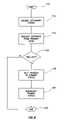
- FIG. 9shows a flow diagram for determining the primary power supply communication module of the preferred embodiment.
- the terms “including” and “comprising”are used in an open-ended fashion, and thus should be interpreted to mean “including, but not limited to . . . ”.
- the term “couple” or “couples”is intended to mean either an indirect or direct electrical connection. Thus, if a first device couples to a second device, that connection may be through a direct electrical connection, or through an indirect electrical connection via other devices and connections.
- Rackis a structural system that forms a frame for mounting other devices therein in a rack mounted computer system.
- the rackcould be as simple as a top, a bottom and four corner pieces forming the structure, but may also include decorative or functional coverings around and on those structural components.
- Chassisa chassis is a structure, typically smaller than the overall rack, that is mounted within the rack. In the preferred embodiments of the present invention, individual servers are mounted in the rack mounted system by insertion into the chassis structures.
- a chassismay alternatively be referred to as a port or an enclosure.
- Serveran individual computer mounted within a rack system. Because most computers mounted in rack systems perform server-type operations, throughout this discussion those devices will be referred to as servers. However, the description herein pertains equally to any computer system performing server operations or otherwise.
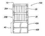
- FIG. 1shows a rack 10 for a rack mounted server system.
- the rack 10preferably comprises a plurality of structural members which form the frame of the rack mounted system.
- On a front portion of the rack 10are a plurality of threaded holes 12 which are adapted to hold various devices within the rack 10 .
- FIG. 2shows a chassis 20 of the preferred embodiment.
- the chassis 20is preferably adapted to slide into the rack 10 and mount at any particular location by use of the knurled knobs 22 A–D. These knurled knobs preferably have a threaded portion (not shown) which couple to the threaded holes 12 of the rack 10 . These knurled knobs 22 A–D, and many other devices familiar to one having ordinary skill in the art, hold the chassis 20 within the rack 10 .
- Each chassis 20 of the preferred embodimentis constructed such that a plurality of servers may be installed therein. Referring still to FIG. 2 , the chassis 20 is preferably adapted to hold the servers 30 in a vertical position. While only three such servers are shown in FIG. 2 , in the preferred embodiment each chassis 20 is adapted to hold eight servers 30 . Further, each chassis 20 is also adapted to hold various communication modules which allow the servers 30 within the chassis 20 to communicate with each other and to external systems and devices.
- FIG. 3shows a front view of a rack mounted server system 100 of the preferred embodiment.
- FIG. 3shows two chassis 20 A and 20 B mounted within the rack 10 .
- Each chassispreferably houses a plurality of servers 30 . While any number of chassis 20 may be used in a server system 100 , the preferred embodiment envisions having at least one, and no more than six chassis 20 in any one system.
- the power supply system 40comprises two power supply assemblies 42 A, B.
- the number of power supply assemblies 42 required for any particular server system 100will be dependent upon the number of chassis 20 and the number of servers 30 within those chassis.
- a server system 100 having six such chassis with each chassis preferably housing eight servers 30preferably two power supply assemblies 42 A, B are required. If more chassis are added, more power supply assemblies 42 may be required. Likewise, if fewer chassis are used, and therefore fewer servers 30 are used, it is possible that the power supply system 40 may include only a single power supply assembly 42 .
- FIG. 4shows an electrical schematic for power distribution in a server system 100 of the preferred embodiment.
- each power supply assembly 42comprises a plurality of individual power supplies 44 , and in the preferred embodiment, each power supply assembly 42 has six such individual power supplies 44 .
- the individual power supplies 44 within a power supply assembly 42are divided into two banks 46 and 48 (the banks 46 and 48 are shown only on power supply assembly 42 B, but are equally applicable to all power supply assemblies). The individual power supplies 44 in each bank 46 , 48 then place their power on respective power supply rails 50 and 52 .
- the power supply rails 50 , 52are fully redundant supplies to the servers 30 in the chassis 20 .
- the bank 46 of the power supply assemblies 42 that feed a particular railare preferably capable of supplying all the necessary power to operate the server system 100 .
- the second bank 48 of the power supply assemblies 42are also preferably adapted to supply all the necessary power to operate the server system 100 . In this way, the power supplies may be operated in a fully redundant fashion.
- FIG. 4indicates this ability by showing that each server 30 is coupled to each power rail 50 , 52 .
- each set of servers 30 in each chassis 20are preferably adapted to have the capability to take their full required operational power from either rail, thus implementing the fall power supply redundancy of the preferred embodiment.
- FIG. 4does not indicate any ability for the servers to communicate with the power supply system 40 .
- the preferred embodiments of the present inventionimplements an intelligent allocation and de-allocation of power. This intelligent allocation and de-allocation requires some form of communication between the power supply system and the computers or servers.
- FIG. 5shows the preferred implementation of a power management system for a rack mounted server system, which allows various components associated with the servers 30 to communicate with the power supply assemblies 42 .
- the preferred embodimentimplements a serial communication pathway 60 coupling each of the power supply assemblies 42 and each chassis 20 .
- This serial communication pathway 60preferably comprises an Institute of Electrical and Electronic Engineers (IEEE) RS-485 compliant system.
- IEEEInstitute of Electrical and Electronic Engineers
- RS-485is preferred, communication between the power supply assemblies 42 and the servers 30 within the chassis 20 may take place by any suitable serial or parallel common communication bus and protocol.
- each chassis 20there may be up to six chassis 20 , each housing eight servers 30 .
- the preferred embodimentmay comprise as many as two power supply assemblies 42 , each having as many as six individual power supplies 44 for a total of twelve individual power supplies 44 .
- the preferred embodimentallowing each individual device to communicate on the serial communication pathway 60 , as many as sixty individual devices would be vying for and arbitrating for the ability to communicate thereon. Additional problems would ensue in such a system in designating a particular primary or other device to make decisions regarding allocation and de-allocation of power.
- each of the power system assemblies 42and each of the chassis 20 , preferably have a communication module that is responsible for relaying messages to the serial communication pathway 60 , and making decisions regarding the allocation and de-allocation of power.
- each power system assembly 42preferably comprises a power supply communication module 70 (PSCM) mounted proximate to its respective power system assembly 42 .
- PSCMpower supply communication module
- each power system communication module 70is mounted on or near a backplane board of each respective power system assembly 42 .
- a power supply communication module 70is responsible for communicating with each individual power supply 44 in its respective power supply assembly 42 to determine parameters of each individual power supply 44 such as fan operability, the internal temperature of the power supply, the power supply input power (incoming AC power), output current, and output amps.
- the power supply communication moduleis also responsible for monitoring power supply assembly 42 level parameters such as operability of external fans, temperature of the operating environment, and power loading of the system. Knowing these parameters is important in implementing the intelligent allocation and de-allocation of power for the entire rack mounted server system 100 .
- the power supply communication module 70is also preferably capable of communication across the serial communication pathway 60 to other power supply communication modules and other chassis communication modules 80 (discussed below).
- Each power supply communication module 70communicates with the individual power supplies 44 in the particular power system assembly 42 by means of a I 2 C bus 72 .
- the I 2 C busis a dual line, multidrop serial bus developed by Philips Semiconductors that comprises a clock line and one data line.
- the devices connected to the I 2 C buscan act as either primary or secondary devices (or alternatively master or slave respectively), and each device is software addressable by a unique address.
- Primary devicescan operate as transmitters, receivers, or combination transmitter/receivers to initiate 8-bit data transfers between devices on the bus.
- the I 2 Cutilizes arbitration to prevent data corruption when two or more master or primary devices desire simultaneously transfer data. Details regarding the I 2 C bus may be found in “The I 2 C-Bus Specification,” Version 2.1 (January 2000), authored by Philips Semiconductors®. Although the I 2 C bus is the preferred communication pathway between the individual power supplies 44 and the power supply communication module 70 , substantially any serial or parallel communication system and protocol would be operable.
- each chassis 20preferably comprises a chassis communication module 80 (CCM).
- the chassis communication module 80preferably communicates with each server 30 within its particular chassis 20 , and preferably relays messages as necessary to and from the serial communication pathway 60 .
- the chassis communication module 80is not only adapted to communicate using the preferred RS-485 on the serial communication pathway 60 , but also preferably communicates to each individual server 30 within its chassis 20 by means of an I 2 C serial communication pathway 82 . While the I 2 C communication pathway 82 is preferred, any suitable communication system and protocol may be used to facilitate the communication.
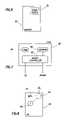
- FIG. 6shows a partial electrical block diagram of a server 30 .
- the serveris preferably a computer system having one or more microprocessors and other devices required for normal computer system operation, but the server 30 preferably does not include a power supply for converting AC power to DC power. However, the server 30 preferably does comprise a DC-DC power supply to convert the preferred ⁇ 48 volt DC power supplied from the power supply system 40 into the required operational voltages for the microprocessor and other sub-systems. Further, the server 30 also comprises a communication device 32 which is at least in part dedicated to communicating over the I 2 C bus 82 with the chassis communication module 80 . As discussed more fully below, this communication device 32 preferably becomes operational just after the server 30 is placed within the chassis 20 .
- the communication device 32is preferably powered and active before the remaining portions of the server 30 are allowed to power up.
- the communication device 32 functionsmay be implemented in any of an array of possible devices familiar to one of ordinary skill in the art. In the preferred embodiments of the present invention, however, the functions of the communication device 32 are implemented in an Application Specific Integrated Circuit (ASIC) along with other functions that are beyond the scope of this specification.
- ASICApplication Specific Integrated Circuit
- the communication device 32 functionscould, likewise, be implemented in a microcontroller programmed to perform such a task, or even in combinational logic.
- FIG. 7shows a more detailed electrical block diagram of the chassis communication module 80 of the preferred embodiment.
- the chassis communication module 80comprises a microcontroller 82 , which is preferably a part No. ZIRCON-LH2 manufactured by Qlogic Corporation.
- This microcontroller 82preferably has external RAM 84 , which is the working area for the microcontroller 82 .
- the microcontroller 82also is preferably coupled to an external EEPROM 86 for semi-permanently storing programs and other data for use by the microcontroller.
- each of the chassis communication modules 80are substantially the same, save their associations with different chassis 20 .
- each power supply communication module 70will be substantially the same as a chassis communication module 80 .
- Software executed by a microcontroller implementing the chassis communication module or the power supply communication modulemay differ given their duties in communicating with different devices.
- the power supply communication modules 70does not require a DC-DC power supply, as auxiliary 5 volt power is preferably available from the individual power supplies 44 .
- the chassis communication modules 80preferably have a DC-DC power supply capable of converting the preferred ⁇ 48 volt DC supply into operable voltages for the on-board microcontroller and related circuitry.
- FIG. 8shows a partial electrical block diagram of an individual power supply 44 . Note that the figure only shows components related to the preferred embodiments—standard power supply components are omitted for the sake of clarity.
- Each power supply 44preferably comprises a health and status monitoring device 45 .
- the health and status monitoring device 45is responsible for monitoring various parameters of the individual power supply 44 to which it is associated.
- the health and status monitoring device 45preferably monitors any internal fans 47 of the power supply, the internal temperature 49 of the power supply 44 , input power, output current, and output voltage.
- the health and status monitoring device 45preferably communicates the gathered information to the power supply communication module 70 by way of the I 2 C bus.
- the health and status monitoring device 45may be as simple as combinational logic designed and constructed to implement the functions, but preferably is a microcontroller programmed to monitor the various parameters of the power supply 44 by way of input signals, and also programmed to communicate with the power supply communication module 70 over the I 2 C bus 72 . If using combinational logic, the health and status monitoring device 45 may also require an interface circuit (not shown) to interface to the I 2 C bus 72 . This interface could be a part no. PCF8575 I 2 C I/O expander manufactured by Phillips Semiconductor.
- the communication device 32(see FIG. 6 ) of the server draws power from either or both of the power rails 50 , 52 . It must be understood, however, that the power drawn by the communication device 32 of the server is very small in comparison to the amount of power required to operate the server 30 . It must further be understood that in the preferred embodiments the servers do not automatically begin their power-up sequence upon insertion into the chassis 20 . Rather, the communication device 32 , after itself being powered and operational, communicates to its respective chassis communication module 80 , requesting permission to draw or allocate power from the power rails 50 , 52 . In the preferred embodiment, the communication device 32 within the server is aware of the total power a server requires.
- the communication device 32refers to the number stored in the EEPROM, and includes that power amount in the request to the chassis communication module 80 .
- the chassis communication module 80relays the request to the primary of the two power supply communication modules 70 (determining which of the power supply communication modules 70 is the primary is discussed more fully below).
- the primary power supply communication moduleprobes its power supplies 44 to make a determination as to available capacity. In the system assumed for purposes of discussion, the primary power supply communication module also asks the secondary power supply communication module to make a similar determination with respect to power capacity in its respective power supply assembly 42 .
- the primary power supply communication moduledetermines that there is enough available capacity to supply the request, then a permission granted message is relayed back to the requesting chassis communication module 80 , which in turn grants permission for the requesting server 30 to draw power and begin the boot process.
- a permission granted messageis relayed back to the requesting chassis communication module 80 , which in turn grants permission for the requesting server 30 to draw power and begin the boot process.
- the preferred embodiment for allocating poweris described in the context of the plugging a first server 30 into a chassis 20 , the operation is substantially the same for any power on operation.
- a server 30 already installed in the chassis 20but powered down. Any of a host of actions may precipitate powering of the server 30 , e.g., pressing of a front panel power button, LAN based requests to power on, and/or activity that requires the server 30 to power on from a sleep state.
- the communication device 32monitors these and any other parameter that may precipitate powering of the server 30 , and prior to allowing the server 30 to
- a servermay be powered down. These reasons may include, but are not limited to, pressing of a power button on the server 30 , performing a software shutdown, or abruptly removing the server 30 .
- the server 30in particular the communication device 32 , preferably communicates with its respective chassis communication module 80 that the power has been released.
- the server 30reduces power consumption, such as by entering a low power mode or sleep state.
- the release of poweris then preferably communicated to the primary power supply communication module 70 . If other servers 30 had previously been denied permission to power on for lack of available power, those servers 30 may now be granted permission. In the case where the server 30 is abruptly removed, the preferred communications may not take place; however, each chassis communication module 80 preferably monitors the presence of each server 30 , and informs the primary power supply communication module 70 of the effective release of power.
- the chassisis substantially populated with servers 30 , each server operating and drawing substantial amounts of power, the demand approaching the total capacity of the power supply system 40 ; or 2) malfinctions of individual power supplies 44 within each power supply assembly 42 have limited the capacity of the overall power supply system 40 .
- another server 30is inserted into a chassis 20 of the rack mounted server system 100 .
- the communication device 32 of the server 30powers up (again a minimal amount of power) and requests permission to power up the individual server.
- the request to draw power from one of the power rails 50 , 52is relayed as discussed above to the primary power supply communication module which makes the determination, as before, as to available power.
- the preferred embodimentrelays a denial of the request back to the requesting server 30 by way of its respective chassis communication module 80 , and thus the server preferably does not power on.
- the primary power supply communication module 70may be programmed to not allow allocation of power beyond that which would jeopardize the power supply system's 40 ability to fully supply necessary power to the rack mounted server system 100 from either of the power rails 50 , 52 . Allocating power to maintain fall redundancy is the preferred implementation, but it is certainly not required. If so desired, the system may operate in a state where full redundancy is not maintained.
- the primary power supply communication module 70is informed of the loss (either by direct communication across its respective I 2 C bus from a power supply 44 , or if the failure was in the power supply assembly associated with the secondary power supply communication module 70 , by communication from the secondary power supply communication).
- the power supply communication modulepreferably requests that individual servers 30 power down to reduce power load. This requesting and powering down of servers 30 preferably continues until the desired operating condition has been restored. Through substantially the same process, servers may again allocate power and become operational once power capacity is restored.
- each server 30 within a rack mounted server system 100is substantially identical at the hardware level to the other servers 30 in the system, some servers may be more critical to the particular operation.
- e-commerceelectronic commerce
- the server system 100is capable of intelligently de-allocating power, for example in emergency situations, from non-critical servers 44 before the critical servers are requested to shut down.
- each server 30 in the rack mounted server system 100is assigned a priority number.
- each chassis 20 within the rack mounted server system 100each chassis having eight servers 30 mounted therein, then 48 total levels of priority will be distributed among the 48 servers.
- the primary power supply communication module 70requests a power or shut down of the lowest priority server. After this server is shut down and its power requirements returned to the pool, the primary power supply communication module 70 again analyzes the power requirements and may again request the next priority level server to be shut down. This procedure continues until enough servers 30 have been shut down to restore the rack mounted computer system into its desired state of operation.
- each chassis communication modulemay be programmed to know the relative importance of each server 30 within its respective chassis 20 .
- the power supply communication modulemay be programmed with this information and thus may request particular servers to be shut down.
- each of the power supply communication modules 70is designated as primary, and the second is designated as a secondary. While it may be possible to hardwire or hardcode this primary and secondary relationship, in the preferred embodiment each of the power supply communication modules 70 is capable of taking on the primary responsibility. Thus, if one power supply communication module 70 is lost due to hardware or communication problems, the second power supply communication module 70 may take over that primary responsibility. However, having the plurality of power supply communication modules 70 in the system each having the capability to be the primary requires some method to select a primary as between competing modules.
- each power supply communication module 70preferably starts this process as indicated in block 110 and then immediately assumes a secondary status as indicated by block 12 . After assuming a secondary status, the communication module 70 requests a response from the primary power supply communication module as indicated in block 114 . In the condition where a power supply communication module has been replaced or is otherwise restarted separate and apart from other power supply communication modules, a primary will already be assigned and thus a response could be expected. However, in the situation where each power supply communication module 70 is starting its sequence substantially simultaneously, there may not be a primary to respond to the request indicated in block 114 .
- a timeris started, and the path taken is dependant upon whether a response from a primary power supply communication is received before the timer runs out as indicated in block 116 . If no response is received before a time out of the timer, the power supply communication module 70 preferably self-promotes to the primary status as indicated in block 118 . After self-promoting to primary, the power supply communication module then broadcasts its primary status as indicated in block 120 . This broadcast is preferably not only to other power supply communication modules, but also to chassis communication modules 80 in the system. In this way, each communication module in the system is aware of which power supply communication module is primary. All communications from the chassis communication modules 80 are thereafter directed to the primary power supply communication module (unless that primary status changes for some reason).
- the length of the timeris preferably set longer than the amount of time it may take that primary to respond.
- the particular power supply communication moduleremains in its secondary status. The flow diagram indicates this feature by having the process move from block 116 to the end block 122 .
- power supply communication modules 70 of the preferred embodimentcommunicate with each other across the RS-485 bus, the determination as to which module will be the primary module is effectively determined as of the time one of these modules wins arbitration on the RS-485 bus to request a response from the primary, as indicated in block 114 .
- the serial communication pathway 60is changed such that multiple simultaneous communication may occur, there may have to be other mechanisms for determining which power supply communication module should be the primary, for example, choosing a primary based upon the highest assigned physical address, or the like.
Landscapes
- Engineering & Computer Science (AREA)
- Theoretical Computer Science (AREA)
- Physics & Mathematics (AREA)
- General Engineering & Computer Science (AREA)
- General Physics & Mathematics (AREA)
- Power Sources (AREA)
Abstract
Description
Claims (28)
Priority Applications (1)
| Application Number | Priority Date | Filing Date | Title |
|---|---|---|---|
| US09/966,180US7043647B2 (en) | 2001-09-28 | 2001-09-28 | Intelligent power management for a rack of servers |
Applications Claiming Priority (1)
| Application Number | Priority Date | Filing Date | Title |
|---|---|---|---|
| US09/966,180US7043647B2 (en) | 2001-09-28 | 2001-09-28 | Intelligent power management for a rack of servers |
Publications (2)
| Publication Number | Publication Date |
|---|---|
| US20030065958A1 US20030065958A1 (en) | 2003-04-03 |
| US7043647B2true US7043647B2 (en) | 2006-05-09 |
Family
ID=25511021
Family Applications (1)
| Application Number | Title | Priority Date | Filing Date |
|---|---|---|---|
| US09/966,180Expired - LifetimeUS7043647B2 (en) | 2001-09-28 | 2001-09-28 | Intelligent power management for a rack of servers |
Country Status (1)
| Country | Link |
|---|---|
| US (1) | US7043647B2 (en) |
Cited By (50)
| Publication number | Priority date | Publication date | Assignee | Title |
|---|---|---|---|---|
| US20040073816A1 (en)* | 2002-10-11 | 2004-04-15 | Compaq Information Technologies Group, L.P. | Cached field replaceable unit EEPROM data |
| US20050086543A1 (en)* | 2003-10-16 | 2005-04-21 | International Business Machines Corporation | Method, apparatus and program product for managing the operation of a computing complex during a utility interruption |
| US20050219827A1 (en)* | 2004-03-31 | 2005-10-06 | Anden Co., Ltd. | Electrical circuit device |
| US20050272402A1 (en)* | 2004-05-10 | 2005-12-08 | Alon Ferentz | Method for rapid port power reduction |
| US20060136754A1 (en)* | 2004-12-16 | 2006-06-22 | Dell Products L.P. | Power-on management for remote power-on signals to high density server module |
| US20060259792A1 (en)* | 2005-05-10 | 2006-11-16 | Dove Daniel J | Rapid load reduction for power-over-LAN system |
| US20070118771A1 (en)* | 2005-11-22 | 2007-05-24 | International Business Machines Corporation | Power management using spare capacity of redundant power supply in blade environment |
| US20070143635A1 (en)* | 2005-12-19 | 2007-06-21 | International Business Machines Corporation | Throttle management for blade system |
| US20070150757A1 (en)* | 2005-12-22 | 2007-06-28 | International Business Machines Corporation | Programmable throttling in blade/chassis power management |
| US20070168088A1 (en)* | 2005-11-02 | 2007-07-19 | Server Technology, Inc. | Power distribution load shedding system and method of use |
| US20070168052A1 (en)* | 2006-01-13 | 2007-07-19 | Zippy Technology Corp. | Identification apparatus for backup-type power supply systems |
| US20070180280A1 (en)* | 2006-02-01 | 2007-08-02 | Bolan Joseph E | Controlling the allocation of power to a plurality of computers whose supply of power is managed by a common power manager |
| US20070185589A1 (en)* | 2004-05-05 | 2007-08-09 | Whirlpool S.A. | Systems and process for energizing loads through a control unit |
| US20070300083A1 (en)* | 2006-06-27 | 2007-12-27 | Goodrum Alan L | Adjusting power budgets of multiple servers |
| US20070300085A1 (en)* | 2006-06-27 | 2007-12-27 | Goodrum Alan L | Maintaining a power budget |
| US20070300084A1 (en)* | 2006-06-27 | 2007-12-27 | Goodrum Alan L | Method and apparatus for adjusting power consumption during server operation |
| US20080010521A1 (en)* | 2006-06-27 | 2008-01-10 | Goodrum Alan L | Determining actual power consumption for system power performance states |
| US20080178018A1 (en)* | 2007-01-19 | 2008-07-24 | Microsoft Corporation | Data structure for budgeting power for multiple devices |
| US20080178019A1 (en)* | 2007-01-19 | 2008-07-24 | Microsoft Corporation | Using priorities and power usage to allocate power budget |
| US20080244311A1 (en)* | 2007-04-02 | 2008-10-02 | John Charles Elliott | System and Method for Thresholding System Power Loss Notifications in a Data Processing System Based on Vital Product Data |
| US20080244283A1 (en)* | 2007-04-02 | 2008-10-02 | John Charles Elliott | System and Method for Thresholding System Power Loss Notifications in a Data Processing System |
| US20080320322A1 (en)* | 2007-06-25 | 2008-12-25 | Green Alan M | Dynamic Converter Control for Efficient Operation |
| US20090034181A1 (en)* | 2007-07-31 | 2009-02-05 | Hewlett-Packard Development Company, L.P. | Cordless power solution for rack-mounted devices |
| US20090089595A1 (en)* | 2007-09-27 | 2009-04-02 | International Busniess Machines Corporation | Managing Computer Power Among A Plurality Of Computers |
| US20090125737A1 (en)* | 2007-11-08 | 2009-05-14 | International Business Machines Corporation | Power Management of an Electronic System |
| US20090125730A1 (en)* | 2007-11-08 | 2009-05-14 | International Business Machines Corporation | Managing Power Consumption In A Computer |
| US20090132842A1 (en)* | 2007-11-15 | 2009-05-21 | International Business Machines Corporation | Managing Computer Power Consumption In A Computer Equipment Rack |
| US20090138219A1 (en)* | 2007-11-28 | 2009-05-28 | International Business Machines Corporation | Estimating power consumption of computing components configured in a computing system |
| US20090193276A1 (en)* | 2008-01-24 | 2009-07-30 | Sudhir Shetty | System and Method for Dynamic Utilization-Based Power Allocation in a Modular Information Handling System |
| US20090254769A1 (en)* | 2006-05-04 | 2009-10-08 | Dell Products L.P. | Power Profiling Application for Managing Power Allocation in an Information Handling System |
| US20100042860A1 (en)* | 2008-08-18 | 2010-02-18 | Electronics And Telecommunications Research Institute | Rack power supply system and method of controlling rack power supply apparatus |
| US20100083010A1 (en)* | 2008-10-01 | 2010-04-01 | International Business Machines Corporation | Power Management For Clusters Of Computers |
| US20100088533A1 (en)* | 2008-10-02 | 2010-04-08 | International Business Machines Corporation | Single Shared Power Domain Dynamic Load Based Power Loss Detection and Notification |
| US20100118019A1 (en)* | 2008-11-12 | 2010-05-13 | International Business Machines Corporation | Dynamically Managing Power Consumption Of A Computer With Graphics Adapter Configurations |
| US20100205469A1 (en)* | 2009-02-06 | 2010-08-12 | Mccarthy Clifford A | Power budgeting for a group of computer systems |
| US20110019352A1 (en)* | 2009-07-23 | 2011-01-27 | Won-Ok Kwon | Rack-mount computer |
| US8103884B2 (en) | 2008-06-25 | 2012-01-24 | International Business Machines Corporation | Managing power consumption of a computer |
| US20120079299A1 (en)* | 2009-06-19 | 2012-03-29 | Cepulis Darren J | Enclosure Power Controller |
| US20120192007A1 (en)* | 2011-01-25 | 2012-07-26 | Dell Products, Lp | System and Method for Extending System Uptime while Running on Backup Power through Power Capping |
| WO2012113808A1 (en)* | 2011-02-22 | 2012-08-30 | Dacentec Be Bvba | A data centre rack comprising a plurality of servers with a control board |
| US8627118B2 (en) | 2010-05-24 | 2014-01-07 | International Business Machines Corporation | Chassis power allocation using expedited power permissions |
| US20140159552A1 (en)* | 2012-12-11 | 2014-06-12 | Panduit Corp. | Equipment Segregation Unit For An Industrial Control Panel |
| US20140297959A1 (en)* | 2013-04-02 | 2014-10-02 | Apple Inc. | Advanced coarse-grained cache power management |
| US9207732B1 (en) | 2015-02-25 | 2015-12-08 | Quanta Computer Inc. | Optimized fan duty control for computing device |
| US9396122B2 (en) | 2013-04-19 | 2016-07-19 | Apple Inc. | Cache allocation scheme optimized for browsing applications |
| US9400544B2 (en) | 2013-04-02 | 2016-07-26 | Apple Inc. | Advanced fine-grained cache power management |
| US20160262283A1 (en)* | 2010-12-23 | 2016-09-08 | Amazon Technologies, Inc. | System with movable computing devices |
| US9958923B2 (en) | 2014-06-20 | 2018-05-01 | Lenovo Enterprise Solutions (Singapore) Pte. Ltd. | Preventing oversubscription to power resources in a computing system |
| US11079947B2 (en) | 2019-02-09 | 2021-08-03 | International Business Machines Corporation | Ensuring hardware-management-console powerup after external AC power loss |
| US11439047B2 (en)* | 2019-10-30 | 2022-09-06 | International Business Machines Corporation | Server racks for hot aisle—cold aisle server rooms |
Families Citing this family (46)
| Publication number | Priority date | Publication date | Assignee | Title |
|---|---|---|---|---|
| US20030033463A1 (en)* | 2001-08-10 | 2003-02-13 | Garnett Paul J. | Computer system storage |
| US6904534B2 (en)* | 2001-09-29 | 2005-06-07 | Hewlett-Packard Development Company, L.P. | Progressive CPU sleep state duty cycle to limit peak power of multiple computers on shared power distribution unit |
| US7138733B2 (en)* | 2001-12-13 | 2006-11-21 | Hewlett-Packard Development Company, L.P. | Redundant data and power infrastructure for modular server components in a rack |
| US6721672B2 (en)* | 2002-01-02 | 2004-04-13 | American Power Conversion | Method and apparatus for preventing overloads of power distribution networks |
| US7400062B2 (en)* | 2002-10-15 | 2008-07-15 | Microsemi Corp. - Analog Mixed Signal Group Ltd. | Rack level power management |
| US7441133B2 (en)* | 2002-10-15 | 2008-10-21 | Microsemi Corp. - Analog Mixed Signal Group Ltd. | Rack level power management for power over Ethernet |
| US7124321B2 (en)* | 2003-02-10 | 2006-10-17 | Sun Microsystems, Inc. | Adaptive throttling |
| US7210048B2 (en)* | 2003-02-14 | 2007-04-24 | Intel Corporation | Enterprise power and thermal management |
| US7418608B2 (en)* | 2004-06-17 | 2008-08-26 | Intel Corporation | Method and an apparatus for managing power consumption of a server |
| US20060156041A1 (en)* | 2005-01-07 | 2006-07-13 | Lee Zaretsky | System and method for power management of plural information handling systems |
| US7392407B2 (en)* | 2005-02-09 | 2008-06-24 | Cisco Technology, Inc. | Method and apparatus for negotiating power between power sourcing equipment and powerable devices |
| US7334140B2 (en)* | 2005-03-03 | 2008-02-19 | International Business Machines Corporation | Apparatus and method to selectively provide power to one or more components disposed in an information storage and retrieval system |
| US7467306B2 (en)* | 2005-03-08 | 2008-12-16 | Hewlett-Packard Development Company, L.P. | Methods and systems for allocating power to an electronic device |
| JP4591149B2 (en)* | 2005-03-29 | 2010-12-01 | 日本電気株式会社 | Cluster system, blade server power control method and program thereof |
| US7647516B2 (en)* | 2005-09-22 | 2010-01-12 | Hewlett-Packard Development Company, L.P. | Power consumption management among compute nodes |
| US7472292B2 (en)* | 2005-10-03 | 2008-12-30 | Hewlett-Packard Development Company, L.P. | System and method for throttling memory power consumption based on status of cover switch of a computer system |
| US20100011229A1 (en)* | 2006-07-17 | 2010-01-14 | Xyratex Technology Limited | Methods of powering up a disk drive storage enclosure and storage enclosures |
| US20080052437A1 (en)* | 2006-08-28 | 2008-02-28 | Dell Products L.P. | Hot Plug Power Policy for Modular Chassis |
| US7831843B2 (en)* | 2006-09-26 | 2010-11-09 | Dell Products L.P. | Apparatus and methods for managing power in an information handling system |
| US7886165B2 (en)* | 2007-05-24 | 2011-02-08 | Broadcom Corporation | Power management for Power-over-Ethernet-capable switch |
| US8151122B1 (en)* | 2007-07-05 | 2012-04-03 | Hewlett-Packard Development Company, L.P. | Power budget managing method and system |
| US8250382B2 (en)* | 2007-08-22 | 2012-08-21 | International Business Machines Corporation | Power control of servers using advanced configuration and power interface (ACPI) states |
| US8775441B2 (en) | 2008-01-16 | 2014-07-08 | Ab Initio Technology Llc | Managing an archive for approximate string matching |
| JP2009218752A (en)* | 2008-03-07 | 2009-09-24 | Nec Corp | Electric power supply device, electric power supply method, electric power supply control program, and network system |
| CN102017822B (en)* | 2008-04-30 | 2015-11-25 | 惠普开发有限公司 | For the power supply module of server cabinet and the method for build-in services device rack power supply |
| US7898117B2 (en)* | 2008-05-22 | 2011-03-01 | International Business Machines Corporation | Modular racks and methods of use |
| US8006112B2 (en)* | 2008-06-09 | 2011-08-23 | Dell Products L.P. | System and method for managing blades after a power supply unit failure |
| US7984311B2 (en) | 2008-08-08 | 2011-07-19 | Dell Products L.P. | Demand based power allocation |
| WO2010018635A1 (en)* | 2008-08-14 | 2010-02-18 | 富士通株式会社 | Cooling method and computer |
| US20100042852A1 (en)* | 2008-08-18 | 2010-02-18 | Huawei Technologies Co., Ltd. | Power-on protection method, module and system |
| CA3014839C (en) | 2008-10-23 | 2019-01-08 | Arlen Anderson | Fuzzy data operations |
| US8327166B2 (en)* | 2009-05-21 | 2012-12-04 | Lsi Corporation | Power managment for storage devices |
| CN103097984B (en)* | 2010-09-16 | 2016-03-02 | 惠普发展公司,有限责任合伙企业 | Power cap system |
| US9361355B2 (en) | 2011-11-15 | 2016-06-07 | Ab Initio Technology Llc | Data clustering based on candidate queries |
| US20140006825A1 (en)* | 2012-06-30 | 2014-01-02 | David Shenhav | Systems and methods to wake up a device from a power conservation state |
| US8925739B2 (en)* | 2012-07-26 | 2015-01-06 | Lenovo Enterprise Solutions (Singapore) Pte. Ltd. | High-capacity computer rack with rear-accessible side bays |
| US9320166B1 (en)* | 2012-12-04 | 2016-04-19 | Amazon Technologies, Inc. | Multi-shelf power-pooling bus |
| US10139878B2 (en)* | 2014-03-17 | 2018-11-27 | Dell Products L.P. | Systems and methods for extended power performance capability discovery for a modular chassis |
| US9832088B2 (en)* | 2014-09-30 | 2017-11-28 | Microsoft Technology Licensing, Llc | Monitoring of shared server set power supply units |
| US10169104B2 (en)* | 2014-11-19 | 2019-01-01 | International Business Machines Corporation | Virtual computing power management |
| US10877551B2 (en)* | 2018-04-11 | 2020-12-29 | Dell Products L.P. | System and method of managing information handling systems |
| US11188142B1 (en)* | 2018-12-11 | 2021-11-30 | Amazon Technologies, Inc. | Power management network for communication between racks in a data center |
| TWI777058B (en)* | 2019-04-01 | 2022-09-11 | 神雲科技股份有限公司 | Power protection device for servers |
| US11178021B2 (en)* | 2019-07-23 | 2021-11-16 | Core Scientific, Inc. | System and method for visually managing computing devices in a data center |
| US20250068219A1 (en)* | 2023-08-25 | 2025-02-27 | Dell Products L.P. | Managing use of hardware bundles through power control |
| US20250306659A1 (en)* | 2024-03-28 | 2025-10-02 | Dell Products L.P. | Prioritization of external power supply throttling for chassis management |
Citations (11)
| Publication number | Priority date | Publication date | Assignee | Title |
|---|---|---|---|---|
| US5216579A (en)* | 1992-01-29 | 1993-06-01 | International Business Machines Corporation | Rack based packaging system for computers with cable, cooling and power management module |
| US5854904A (en)* | 1996-10-15 | 1998-12-29 | Brown; Erik Lee | Object-oriented modular electronic component system |
| US6225708B1 (en)* | 1998-06-05 | 2001-05-01 | International Business Machine Corporation | Uninterruptable power supply |
| US6483204B2 (en)* | 2000-06-30 | 2002-11-19 | Mitsubishi Denki Kabushiki Kaisha | Power supply system with information exchange between plural loads and plural power sources |
| US20030005339A1 (en)* | 2001-06-29 | 2003-01-02 | Cohen Paul M. | Power control for a computer system |
| US20030023885A1 (en)* | 2001-07-25 | 2003-01-30 | Potter Mark R. | Automated power management system for a network of computers |
| US20030037150A1 (en)* | 2001-07-31 | 2003-02-20 | Nakagawa O. Sam | System and method for quality of service based server cluster power management |
| US20030112582A1 (en) | 2001-12-13 | 2003-06-19 | Sanders Michael C. | Redundant data and power infrastructure for modular server components in a rack |
| US6594771B1 (en)* | 2000-04-13 | 2003-07-15 | Hewlett-Packard Development Company, L.P. | Method and apparatus for managing power in an electronic device |
| US20040073816A1 (en) | 2002-10-11 | 2004-04-15 | Compaq Information Technologies Group, L.P. | Cached field replaceable unit EEPROM data |
| US6785827B2 (en)* | 2000-11-29 | 2004-08-31 | Dell Products L.P. | System for determining servers power supply requirement by sampling power usage values thereof at a rate based upon the criticality of its availability |
- 2001
- 2001-09-28USUS09/966,180patent/US7043647B2/ennot_activeExpired - Lifetime
Patent Citations (11)
| Publication number | Priority date | Publication date | Assignee | Title |
|---|---|---|---|---|
| US5216579A (en)* | 1992-01-29 | 1993-06-01 | International Business Machines Corporation | Rack based packaging system for computers with cable, cooling and power management module |
| US5854904A (en)* | 1996-10-15 | 1998-12-29 | Brown; Erik Lee | Object-oriented modular electronic component system |
| US6225708B1 (en)* | 1998-06-05 | 2001-05-01 | International Business Machine Corporation | Uninterruptable power supply |
| US6594771B1 (en)* | 2000-04-13 | 2003-07-15 | Hewlett-Packard Development Company, L.P. | Method and apparatus for managing power in an electronic device |
| US6483204B2 (en)* | 2000-06-30 | 2002-11-19 | Mitsubishi Denki Kabushiki Kaisha | Power supply system with information exchange between plural loads and plural power sources |
| US6785827B2 (en)* | 2000-11-29 | 2004-08-31 | Dell Products L.P. | System for determining servers power supply requirement by sampling power usage values thereof at a rate based upon the criticality of its availability |
| US20030005339A1 (en)* | 2001-06-29 | 2003-01-02 | Cohen Paul M. | Power control for a computer system |
| US20030023885A1 (en)* | 2001-07-25 | 2003-01-30 | Potter Mark R. | Automated power management system for a network of computers |
| US20030037150A1 (en)* | 2001-07-31 | 2003-02-20 | Nakagawa O. Sam | System and method for quality of service based server cluster power management |
| US20030112582A1 (en) | 2001-12-13 | 2003-06-19 | Sanders Michael C. | Redundant data and power infrastructure for modular server components in a rack |
| US20040073816A1 (en) | 2002-10-11 | 2004-04-15 | Compaq Information Technologies Group, L.P. | Cached field replaceable unit EEPROM data |
Cited By (88)
| Publication number | Priority date | Publication date | Assignee | Title |
|---|---|---|---|---|
| US20040073816A1 (en)* | 2002-10-11 | 2004-04-15 | Compaq Information Technologies Group, L.P. | Cached field replaceable unit EEPROM data |
| US7739485B2 (en) | 2002-10-11 | 2010-06-15 | Hewlett-Packard Development Company, L.P. | Cached field replaceable unit EEPROM data |
| US20050086543A1 (en)* | 2003-10-16 | 2005-04-21 | International Business Machines Corporation | Method, apparatus and program product for managing the operation of a computing complex during a utility interruption |
| US7451336B2 (en)* | 2003-10-16 | 2008-11-11 | International Business Machines Corporation | Automated load shedding of powered devices in a computer complex in the event of utility interruption |
| US20050219827A1 (en)* | 2004-03-31 | 2005-10-06 | Anden Co., Ltd. | Electrical circuit device |
| US8035248B2 (en)* | 2004-05-05 | 2011-10-11 | Whirlpool S.A. | Systems and process for energizing loads through a control unit |
| US20070185589A1 (en)* | 2004-05-05 | 2007-08-09 | Whirlpool S.A. | Systems and process for energizing loads through a control unit |
| US20050272402A1 (en)* | 2004-05-10 | 2005-12-08 | Alon Ferentz | Method for rapid port power reduction |
| US7337336B2 (en)* | 2004-05-10 | 2008-02-26 | Microsemi Corp.-Analog Mixed Signal Group Ltd. | Method for rapid port power reduction |
| US20060136754A1 (en)* | 2004-12-16 | 2006-06-22 | Dell Products L.P. | Power-on management for remote power-on signals to high density server module |
| US7325149B2 (en)* | 2004-12-16 | 2008-01-29 | Dell Products L.P. | Power-on management for remote power-on signals to high density server module |
| US20060259792A1 (en)* | 2005-05-10 | 2006-11-16 | Dove Daniel J | Rapid load reduction for power-over-LAN system |
| US7340620B2 (en)* | 2005-05-10 | 2008-03-04 | Hewlett-Packard Development Company, L.P. | Rapid load reduction for power-over-LAN system using lower and higher priority states for ports |
| US20070168088A1 (en)* | 2005-11-02 | 2007-07-19 | Server Technology, Inc. | Power distribution load shedding system and method of use |
| US20070118771A1 (en)* | 2005-11-22 | 2007-05-24 | International Business Machines Corporation | Power management using spare capacity of redundant power supply in blade environment |
| US7457976B2 (en)* | 2005-11-22 | 2008-11-25 | International Business Machines Corporation | Power management using spare capacity of redundant power supply in blade environment |
| US7650517B2 (en)* | 2005-12-19 | 2010-01-19 | International Business Machines Corporation | Throttle management for blade system |
| US20070143635A1 (en)* | 2005-12-19 | 2007-06-21 | International Business Machines Corporation | Throttle management for blade system |
| US7493503B2 (en)* | 2005-12-22 | 2009-02-17 | International Business Machines Corporation | Programmable throttling in blade/chassis power management |
| US20070150757A1 (en)* | 2005-12-22 | 2007-06-28 | International Business Machines Corporation | Programmable throttling in blade/chassis power management |
| US7725753B2 (en)* | 2006-01-13 | 2010-05-25 | Zippy Technology Corp. | Identification apparatus for backup-type power supply systems |
| US20070168052A1 (en)* | 2006-01-13 | 2007-07-19 | Zippy Technology Corp. | Identification apparatus for backup-type power supply systems |
| US20070180280A1 (en)* | 2006-02-01 | 2007-08-02 | Bolan Joseph E | Controlling the allocation of power to a plurality of computers whose supply of power is managed by a common power manager |
| US8402296B2 (en)* | 2006-05-04 | 2013-03-19 | Dell Products L.P. | Power profiling application for managing power allocation in an information handling system |
| US20090254769A1 (en)* | 2006-05-04 | 2009-10-08 | Dell Products L.P. | Power Profiling Application for Managing Power Allocation in an Information Handling System |
| US8639962B2 (en) | 2006-05-04 | 2014-01-28 | Dell Products L.P. | Power profiling application for managing power allocation in an information handling system |
| US7757107B2 (en) | 2006-06-27 | 2010-07-13 | Hewlett-Packard Development Company, L.P. | Maintaining a power budget |
| US7702931B2 (en)* | 2006-06-27 | 2010-04-20 | Hewlett-Packard Development Company, L.P. | Adjusting power budgets of multiple servers |
| US20070300085A1 (en)* | 2006-06-27 | 2007-12-27 | Goodrum Alan L | Maintaining a power budget |
| US7739548B2 (en) | 2006-06-27 | 2010-06-15 | Hewlett-Packard Development Company, L.P. | Determining actual power consumption for system power performance states |
| US20070300083A1 (en)* | 2006-06-27 | 2007-12-27 | Goodrum Alan L | Adjusting power budgets of multiple servers |
| US7607030B2 (en) | 2006-06-27 | 2009-10-20 | Hewlett-Packard Development Company, L.P. | Method and apparatus for adjusting power consumption during server initial system power performance state |
| US20080010521A1 (en)* | 2006-06-27 | 2008-01-10 | Goodrum Alan L | Determining actual power consumption for system power performance states |
| US20070300084A1 (en)* | 2006-06-27 | 2007-12-27 | Goodrum Alan L | Method and apparatus for adjusting power consumption during server operation |
| CN101589574B (en)* | 2007-01-19 | 2012-11-28 | 微软公司 | Data structure for budgeting power for multiple devices |
| US20080178019A1 (en)* | 2007-01-19 | 2008-07-24 | Microsoft Corporation | Using priorities and power usage to allocate power budget |
| US7793126B2 (en) | 2007-01-19 | 2010-09-07 | Microsoft Corporation | Using priorities and power usage to allocate power budget |
| US7793120B2 (en)* | 2007-01-19 | 2010-09-07 | Microsoft Corporation | Data structure for budgeting power for multiple devices |
| US20080178018A1 (en)* | 2007-01-19 | 2008-07-24 | Microsoft Corporation | Data structure for budgeting power for multiple devices |
| US20080244311A1 (en)* | 2007-04-02 | 2008-10-02 | John Charles Elliott | System and Method for Thresholding System Power Loss Notifications in a Data Processing System Based on Vital Product Data |
| US20080244283A1 (en)* | 2007-04-02 | 2008-10-02 | John Charles Elliott | System and Method for Thresholding System Power Loss Notifications in a Data Processing System |
| US7937602B2 (en) | 2007-04-02 | 2011-05-03 | International Business Machines Corporation | System and method for thresholding system power loss notifications in a data processing system based on current distribution network configuration |
| US7747900B2 (en)* | 2007-04-02 | 2010-06-29 | International Business Machines Corporation | Thresholding system power loss notifications in a data processing system based on vital product data |
| US20080320322A1 (en)* | 2007-06-25 | 2008-12-25 | Green Alan M | Dynamic Converter Control for Efficient Operation |
| US7895455B2 (en)* | 2007-06-25 | 2011-02-22 | Hewlett-Packard Development Company, L.P. | Dynamic converter control for efficient operation |
| US20090034181A1 (en)* | 2007-07-31 | 2009-02-05 | Hewlett-Packard Development Company, L.P. | Cordless power solution for rack-mounted devices |
| US20090089595A1 (en)* | 2007-09-27 | 2009-04-02 | International Busniess Machines Corporation | Managing Computer Power Among A Plurality Of Computers |
| US7925911B2 (en) | 2007-09-27 | 2011-04-12 | International Business Machines Corporation | Managing computer power among a plurality of computers |
| US8006108B2 (en) | 2007-11-08 | 2011-08-23 | International Business Machines Corporation | Dynamic selection of group and device power limits |
| US20090125730A1 (en)* | 2007-11-08 | 2009-05-14 | International Business Machines Corporation | Managing Power Consumption In A Computer |
| US20090125737A1 (en)* | 2007-11-08 | 2009-05-14 | International Business Machines Corporation | Power Management of an Electronic System |
| US8166326B2 (en) | 2007-11-08 | 2012-04-24 | International Business Machines Corporation | Managing power consumption in a computer |
| US20090132842A1 (en)* | 2007-11-15 | 2009-05-21 | International Business Machines Corporation | Managing Computer Power Consumption In A Computer Equipment Rack |
| US20090138219A1 (en)* | 2007-11-28 | 2009-05-28 | International Business Machines Corporation | Estimating power consumption of computing components configured in a computing system |
| US8041521B2 (en) | 2007-11-28 | 2011-10-18 | International Business Machines Corporation | Estimating power consumption of computing components configured in a computing system |
| US20090193276A1 (en)* | 2008-01-24 | 2009-07-30 | Sudhir Shetty | System and Method for Dynamic Utilization-Based Power Allocation in a Modular Information Handling System |
| US7996690B2 (en)* | 2008-01-24 | 2011-08-09 | Dell Products L.P. | System and method for dynamic utilization-based power allocation in a modular information handling system |
| US8103884B2 (en) | 2008-06-25 | 2012-01-24 | International Business Machines Corporation | Managing power consumption of a computer |
| US20100042860A1 (en)* | 2008-08-18 | 2010-02-18 | Electronics And Telecommunications Research Institute | Rack power supply system and method of controlling rack power supply apparatus |
| US20100083010A1 (en)* | 2008-10-01 | 2010-04-01 | International Business Machines Corporation | Power Management For Clusters Of Computers |
| US8041976B2 (en) | 2008-10-01 | 2011-10-18 | International Business Machines Corporation | Power management for clusters of computers |
| US20100088533A1 (en)* | 2008-10-02 | 2010-04-08 | International Business Machines Corporation | Single Shared Power Domain Dynamic Load Based Power Loss Detection and Notification |
| US8190925B2 (en) | 2008-10-02 | 2012-05-29 | International Business Machines Corporation | Single shared power domain dynamic load based power loss detection and notification |
| US8301920B2 (en) | 2008-10-02 | 2012-10-30 | International Business Machines Corporation | Shared power domain dynamic load based power loss detection and notification |
| US20100118019A1 (en)* | 2008-11-12 | 2010-05-13 | International Business Machines Corporation | Dynamically Managing Power Consumption Of A Computer With Graphics Adapter Configurations |
| US8514215B2 (en) | 2008-11-12 | 2013-08-20 | International Business Machines Corporation | Dynamically managing power consumption of a computer with graphics adapter configurations |
| US20100205469A1 (en)* | 2009-02-06 | 2010-08-12 | Mccarthy Clifford A | Power budgeting for a group of computer systems |
| US8255709B2 (en) | 2009-02-06 | 2012-08-28 | Hewlett-Packard Development Company, L.P. | Power budgeting for a group of computer systems using utilization feedback for manageable components |
| US9778722B2 (en) | 2009-06-19 | 2017-10-03 | Hewlett Packard Enterprise Development Lp | Enclosure power controller |
| US20120079299A1 (en)* | 2009-06-19 | 2012-03-29 | Cepulis Darren J | Enclosure Power Controller |
| US9058155B2 (en)* | 2009-06-19 | 2015-06-16 | Hewlett-Packard Development Company, L.P. | Enclosure power controller providing plurality of power control signals to plurality of removable compute nodes based on a duty cycle of each power control signal |
| US20110019352A1 (en)* | 2009-07-23 | 2011-01-27 | Won-Ok Kwon | Rack-mount computer |
| US8627118B2 (en) | 2010-05-24 | 2014-01-07 | International Business Machines Corporation | Chassis power allocation using expedited power permissions |
| US10237998B2 (en)* | 2010-12-23 | 2019-03-19 | Amazon Technologies, Inc. | System with movable computing devices |
| US20160262283A1 (en)* | 2010-12-23 | 2016-09-08 | Amazon Technologies, Inc. | System with movable computing devices |
| US20120192007A1 (en)* | 2011-01-25 | 2012-07-26 | Dell Products, Lp | System and Method for Extending System Uptime while Running on Backup Power through Power Capping |
| US8612801B2 (en)* | 2011-01-25 | 2013-12-17 | Dell Products, Lp | System and method for extending system uptime while running on backup power |
| WO2012113808A1 (en)* | 2011-02-22 | 2012-08-30 | Dacentec Be Bvba | A data centre rack comprising a plurality of servers with a control board |
| US9236717B2 (en)* | 2012-12-11 | 2016-01-12 | Panduit Corp. | Equipment segregation unit for an industrial control panel |
| US20140159552A1 (en)* | 2012-12-11 | 2014-06-12 | Panduit Corp. | Equipment Segregation Unit For An Industrial Control Panel |
| US8984227B2 (en)* | 2013-04-02 | 2015-03-17 | Apple Inc. | Advanced coarse-grained cache power management |
| US20140297959A1 (en)* | 2013-04-02 | 2014-10-02 | Apple Inc. | Advanced coarse-grained cache power management |
| US9400544B2 (en) | 2013-04-02 | 2016-07-26 | Apple Inc. | Advanced fine-grained cache power management |
| US9396122B2 (en) | 2013-04-19 | 2016-07-19 | Apple Inc. | Cache allocation scheme optimized for browsing applications |
| US9958923B2 (en) | 2014-06-20 | 2018-05-01 | Lenovo Enterprise Solutions (Singapore) Pte. Ltd. | Preventing oversubscription to power resources in a computing system |
| US9207732B1 (en) | 2015-02-25 | 2015-12-08 | Quanta Computer Inc. | Optimized fan duty control for computing device |
| US11079947B2 (en) | 2019-02-09 | 2021-08-03 | International Business Machines Corporation | Ensuring hardware-management-console powerup after external AC power loss |
| US11439047B2 (en)* | 2019-10-30 | 2022-09-06 | International Business Machines Corporation | Server racks for hot aisle—cold aisle server rooms |
Also Published As
| Publication number | Publication date |
|---|---|
| US20030065958A1 (en) | 2003-04-03 |
Similar Documents
| Publication | Publication Date | Title |
|---|---|---|
| US7043647B2 (en) | Intelligent power management for a rack of servers | |
| KR102801566B1 (en) | Systems, methods, and devices for providing power to devices through connectors | |
| US7051215B2 (en) | Power management for clustered computing platforms | |
| JP3672309B2 (en) | System and method for managing power | |
| US5652893A (en) | Switching hub intelligent power management | |
| US7461274B2 (en) | Method for maximizing server utilization in a resource constrained environment | |
| US6594771B1 (en) | Method and apparatus for managing power in an electronic device | |
| US8694810B2 (en) | Server power management with automatically-expiring server power allocations | |
| US8751836B1 (en) | Data storage system and method for monitoring and controlling the power budget in a drive enclosure housing data storage devices | |
| US8006112B2 (en) | System and method for managing blades after a power supply unit failure | |
| US7636862B2 (en) | Modular server system | |
| US20060031448A1 (en) | On demand server blades | |
| US20050246562A1 (en) | Interchangeable power over Ethernet module | |
| US7739485B2 (en) | Cached field replaceable unit EEPROM data | |
| JP2005025745A (en) | Apparatus and method for real-time power distribution management | |
| US20030061312A1 (en) | Reduction of configuration time upon deployment of a configurable device in a shared resource environment | |
| GB2485643A (en) | Rack-level modular server and storage framework. | |
| WO2006007146A2 (en) | A method and apparatus for managing power consumption of a server | |
| US7206947B2 (en) | System and method for providing a persistent power mask | |
| US8112534B2 (en) | Apparatus and method for remote power control | |
| US9003206B2 (en) | Managing communication and control of power components | |
| US20030065730A1 (en) | Method for determining a primary communication module | |
| CN107533348B (en) | Method and apparatus for thermally managing a high performance computing system and computer readable medium | |
| US8984202B2 (en) | Multiple host support for remote expansion apparatus | |
| US11327549B2 (en) | Method and apparatus for improving power management by controlling operations of an uninterruptible power supply in a data center |
Legal Events
| Date | Code | Title | Description |
|---|---|---|---|
| AS | Assignment | Owner name:COMPAQ INFORMATION TECHNOLOGIES GROUP, L.P., TEXAS Free format text:ASSIGNMENT OF ASSIGNORS INTEREST;ASSIGNORS:HANSEN, PETER A.;BROWN, ANDREW;JONES, KEVIN M.;AND OTHERS;REEL/FRAME:012228/0447;SIGNING DATES FROM 20010907 TO 20010927 | |
| AS | Assignment | Owner name:HEWLETT-PACKARD DEVELOPMENT COMPANY, L.P., TEXAS Free format text:CHANGE OF NAME;ASSIGNOR:COMPAQ INFORMATION TECHNOLOGIES GROUP LP;REEL/FRAME:014628/0103 Effective date:20021001 | |
| STCF | Information on status: patent grant | Free format text:PATENTED CASE | |
| CC | Certificate of correction | ||
| FPAY | Fee payment | Year of fee payment:4 | |
| FPAY | Fee payment | Year of fee payment:8 | |
| AS | Assignment | Owner name:HEWLETT PACKARD ENTERPRISE DEVELOPMENT LP, TEXAS Free format text:ASSIGNMENT OF ASSIGNORS INTEREST;ASSIGNOR:HEWLETT-PACKARD DEVELOPMENT COMPANY, L.P.;REEL/FRAME:037079/0001 Effective date:20151027 | |
| MAFP | Maintenance fee payment | Free format text:PAYMENT OF MAINTENANCE FEE, 12TH YEAR, LARGE ENTITY (ORIGINAL EVENT CODE: M1553) Year of fee payment:12 |