US7043303B1 - Enhanced methods for determining iso-loudness contours for fitting cochlear implant sound processors - Google Patents
Enhanced methods for determining iso-loudness contours for fitting cochlear implant sound processorsDownload PDFInfo
- Publication number
- US7043303B1 US7043303B1US10/647,372US64737203AUS7043303B1US 7043303 B1US7043303 B1US 7043303B1US 64737203 AUS64737203 AUS 64737203AUS 7043303 B1US7043303 B1US 7043303B1
- Authority
- US
- United States
- Prior art keywords
- iso
- channel
- loudness
- contour
- loudness contour
- Prior art date
- Legal status (The legal status is an assumption and is not a legal conclusion. Google has not performed a legal analysis and makes no representation as to the accuracy of the status listed.)
- Expired - Fee Related, expires
Links
- 238000000034methodMethods0.000titleclaimsabstractdescription78
- 239000007943implantSubstances0.000titleclaimsabstractdescription51
- 230000000638stimulationEffects0.000claimsabstractdescription97
- 230000004044responseEffects0.000claimsabstractdescription12
- 210000003477cochleaAnatomy0.000claimsdescription12
- 230000000541pulsatile effectEffects0.000claimsdescription8
- 238000003384imaging methodMethods0.000claimsdescription3
- 230000008904neural responseEffects0.000claimsdescription3
- 210000000133brain stemAnatomy0.000claimsdescription2
- 230000000763evoking effectEffects0.000claimsdescription2
- FGUUSXIOTUKUDN-IBGZPJMESA-NC1(=CC=CC=C1)N1C2=C(NC([C@H](C1)NC=1OC(=NN=1)C1=CC=CC=C1)=O)C=CC=C2Chemical compoundC1(=CC=CC=C1)N1C2=C(NC([C@H](C1)NC=1OC(=NN=1)C1=CC=CC=C1)=O)C=CC=C2FGUUSXIOTUKUDN-IBGZPJMESA-N0.000claims1
- 230000008569processEffects0.000abstractdescription17
- 230000017105transpositionEffects0.000abstractdescription4
- 108091006146ChannelsProteins0.000description96
- 239000011664nicotinic acidSubstances0.000description24
- 238000004458analytical methodMethods0.000description13
- 238000012545processingMethods0.000description13
- 238000004891communicationMethods0.000description8
- 230000006870functionEffects0.000description8
- 230000005236sound signalEffects0.000description7
- 230000008901benefitEffects0.000description6
- 230000002051biphasic effectEffects0.000description5
- 238000010586diagramMethods0.000description5
- 238000005259measurementMethods0.000description5
- 230000013707sensory perception of soundEffects0.000description5
- 238000013507mappingMethods0.000description4
- 230000004936stimulating effectEffects0.000description4
- 238000012360testing methodMethods0.000description4
- 230000009286beneficial effectEffects0.000description3
- 210000000860cochlear nerveAnatomy0.000description3
- 230000001965increasing effectEffects0.000description3
- 101100126074Caenorhabditis elegans imp-2 geneProteins0.000description2
- 230000005540biological transmissionEffects0.000description2
- 230000005284excitationEffects0.000description2
- 238000002513implantationMethods0.000description2
- 230000001537neural effectEffects0.000description2
- 235000001968nicotinic acidNutrition0.000description2
- 230000008447perceptionEffects0.000description2
- 230000000717retained effectEffects0.000description2
- 238000005070samplingMethods0.000description2
- 208000032041Hearing impairedDiseases0.000description1
- 230000004913activationEffects0.000description1
- 230000006978adaptationEffects0.000description1
- 230000004075alterationEffects0.000description1
- 238000013459approachMethods0.000description1
- 238000003491arrayMethods0.000description1
- 239000003990capacitorSubstances0.000description1
- 239000004020conductorSubstances0.000description1
- 230000001419dependent effectEffects0.000description1
- 238000001514detection methodMethods0.000description1
- 210000000613ear canalAnatomy0.000description1
- 210000000883ear externalAnatomy0.000description1
- 210000003027ear innerAnatomy0.000description1
- 210000000959ear middleAnatomy0.000description1
- 238000002847impedance measurementMethods0.000description1
- 230000001939inductive effectEffects0.000description1
- 238000012986modificationMethods0.000description1
- 230000004048modificationEffects0.000description1
- 239000000047productSubstances0.000description1
- 230000035807sensationEffects0.000description1
- 238000004088simulationMethods0.000description1
- 238000000638solvent extractionMethods0.000description1
- 239000013589supplementSubstances0.000description1
- 230000002123temporal effectEffects0.000description1
Images


Classifications
- A—HUMAN NECESSITIES
- A61—MEDICAL OR VETERINARY SCIENCE; HYGIENE
- A61N—ELECTROTHERAPY; MAGNETOTHERAPY; RADIATION THERAPY; ULTRASOUND THERAPY
- A61N1/00—Electrotherapy; Circuits therefor
- A61N1/18—Applying electric currents by contact electrodes
- A61N1/32—Applying electric currents by contact electrodes alternating or intermittent currents
- A61N1/36—Applying electric currents by contact electrodes alternating or intermittent currents for stimulation
- A61N1/36036—Applying electric currents by contact electrodes alternating or intermittent currents for stimulation of the outer, middle or inner ear
- A61N1/36038—Cochlear stimulation
- A61N1/36039—Cochlear stimulation fitting procedures
- A—HUMAN NECESSITIES
- A61—MEDICAL OR VETERINARY SCIENCE; HYGIENE
- A61N—ELECTROTHERAPY; MAGNETOTHERAPY; RADIATION THERAPY; ULTRASOUND THERAPY
- A61N1/00—Electrotherapy; Circuits therefor
- A61N1/18—Applying electric currents by contact electrodes
- A61N1/32—Applying electric currents by contact electrodes alternating or intermittent currents
- A61N1/36—Applying electric currents by contact electrodes alternating or intermittent currents for stimulation
- A61N1/36036—Applying electric currents by contact electrodes alternating or intermittent currents for stimulation of the outer, middle or inner ear
- A61N1/36038—Cochlear stimulation
Definitions
- the present inventionrelates to cochlear implants, and more particularly to simplified methods for fitting cochlear implants that, in many instances, do not require patient feedback, clinician involvement, and/or measurement of minimum perception thresholds, and may be used with a variety of cochlear implant systems.
- the electrode array shown in the '590 patentcomprises a plurality of exposed electrode pairs spaced along and imbedded in a resilient curved base for implantation in accordance with a method of surgical implantation, e.g., as described in U.S. Pat. No. 3,751,615.
- the system described in the '590 patentreceives audio signals, i.e., sound waves, at a signal processor (or speech processor) located outside the body of a hearing impaired patient.
- the speech processorconverts the received audio signals into modulated RF data signals that are transmitted through the patient's skin and then by a cable connection to an implanted multi-channel intra-cochlear electrode array.
- the modulated RF signalsare demodulated into analog signals and are applied to selected ones of the plurality of exposed electrode pairs in the intra-cochlear electrode so as to electrically stimulate predetermined locations of the auditory nerve within the cochlea.
- U.S. Pat. No. 5,938,691shows an improved multi-channel cochlear stimulation system employing an implanted cochlear stimulator (ICS) and an externally wearable speech processor (SP).
- the speech processoremploys a headpiece that is placed adjacent to the ear of the patient, which receives audio signals and transmits the audio signals back to the speech processor.
- the speech processorreceives and processes the audio signals and generates data indicative of the audio signals for transcutaneous transmission to the implantable cochlear stimulator.
- the implantable cochlear stimulatorreceives the transmission from the speech processor and applies stimulation signals to a plurality of cochlea stimulating channels, each having a pair of electrodes in an electrode array associated therewith. Each of the cochlea stimulating channels uses a capacitor to couple the electrodes of the electrode array.
- a new, more sophisticated, class of cochlear implantreferred to as a bionic ear, is now available, providing patients with enhanced hearing performance.
- a bionic earFor example, Advanced Bionics® Corporation, of Sylmar, Calif., currently offers a cochlear implant which it refers to as the CII Bionic Ear® cochlear implant.
- CII Bionic Ear® cochlear implantMany features associated with the CII Bionic Ear® implant are described in U.S. Pat. No. 6,219,580, incorporated herein by reference.
- the added complexity of the CII Bionic Ear® cochlear implantincludes higher numbers of channels, arbitrary simultaneous grouping, intra-phase gaps, binaural capabilities, and the like.
- the Bionic Ear implantcontains advances in, e.g., internal memory banks, that enable it to send very detailed, high resolution sound signals to the auditory nerve. Such signals are delivered to the auditory nerve using a special electrode adapted to be inserted into the cochlea.
- a representative electrode usable with the CII Bionic Ear®is described in U.S. Pat. No. 6,129,753, also incorporated herein by reference.
- the implantable cochlear stimulators described in at least the '629, '474, '861, '580, and '704 patentsare able to selectively control the pulse width of stimulating pulses that are applied through the electrode array to the cochlea, and the frequency at which the stimulating pulses are applied.
- the implanted portion of the cochlear stimulation system, and the externally wearable processorhave become increasingly complicated and sophisticated.
- much of the circuitry previously employed in the externally wearable processorhas been moved to the implanted portion, thereby reducing the amount of information that must be transmitted from the external wearable processor to the implanted portion.
- the amount of control and discretion exercisable by an audiologist in selecting the modes and methods of operation of the cochlear stimulation systemhave increased dramatically and it is no longer possible to fully control and customize the operation of the cochlear stimulation system through the use of, for example, switches located on the speech processor.
- the '247 patentdescribes representative stimulation strategies (a.k.a., speech processing strategies) that may be employed by a multichannel stimulation system. Such strategies define patterns of stimulation waveforms that are to be applied to the electrodes as controlled electrical currents. For instance, the speech processing strategy is used, inter alia, to condition the magnitude and polarity of the stimulation current applied to the implanted electrodes of the electrode array.
- speech processing strategiesa.k.a., speech processing strategies
- the types of stimulation patterns applied to the multiple channelsmay be broadly classified as: (1) simultaneous stimulation patterns (substantially all electrodes receive current stimuli at the same time, thereby approximating an analog signal), or (2) sequential or non-simultaneous stimulation patterns (only one electrode receives a current pulse at one time).
- simultaneous stimulation patternsmay be “fully” simultaneous or partially simultaneous.
- a fully simultaneous stimulation patternis one wherein stimulation currents, either analog or pulsatile, are applied to the electrodes of all of the available channels at the same time.
- a partially simultaneous stimulation patternis one where stimulation currents, either analog or pulsatile, are applied to the electrodes of two or more channels, but not necessarily all of the channels, at the same time.
- a minimum threshold levelis measured, typically referred to as a “T” level, which represents the minimum stimulation current which, when applied to a given electrode associated with the channel, produces a sensed perception of sound at least 50% of the time.
- an “M” levelis determined for each channel, which represents a stimulation current which, when applied to the given electrode, produces a sensed perception of sound that is moderately loud, or comfortably loud, but not so loud that the perceived sound is uncomfortable.
- the present inventionsimplifies the cochlear implant fitting process for various cochlear prostheses and stimulation strategies, including high rate stimulation strategies. For instance, patient self-programming is made possible with the present invention.
- the present inventionalso allows auto-fitting (particularly useful for very young patients and other patients from whom it is challenging to obtain feedback) using iso-neural response contours to predict iso-loudness contours and which can be linearly transposed.
- the present inventionteaches linear transposition of M iso-loudness contours (or iso-neural contours) to determine T iso-loudness contours.
- wider pulse widthscan be used to generate an iso-loudness contour whose shape can be used (via linear transposition) for the programming of high-rate, narrow pulse width stimulation.
- the present inventionprovides fitting systems allowing one or combinations of:
- fittingis simplified, less time consuming, and potentially has improved results.
- the present inventionmay allow the patient to continually update their fitting, possibly without the aid of a clinician.
- FIG. 1Ashows an exemplary cochlear implant system
- FIG. 1Bis a block diagram of an exemplary cochlear system
- FIG. 2Adepicts the elements of a typical fitting system used with a typical cochlear stimulation system
- FIG. 2Bdepicts the elements of an alternate fitting system
- FIGS. 3A–3Hshow exemplary displays and workflow associated with aspects of a method of M iso-loudness contour determinations of the present invention
- FIGS. 4A and 4Bshow exemplary displays and workflow associated with other aspects of M iso-loudness contour determinations of the present invention
- FIG. 5shows an exemplary display associated with an optional aspect of a method of M iso-loudness contour determination of the present invention.
- FIGS. 6A and 6Bdepict exemplary screen displays associated with a method of T iso-loudness contour determination of the present invention.
- CLARION®, CII Bionic Ear®, and HiRes90K® systemsare not the subject of the invention, per se, many of the details associated with the CLARION®, CII Bionic Ear®, and HiRes90K® cochlear prostheses, including their electrodes, electrode arrays, implantable cochlear stimulators (ICSs), speech processors, and headpieces, are not presented herein, but may be found elsewhere, or are known in the art.
- the CLARION® ICSis described, inter alia, in U.S. Pat. No. 5,603,726, which is incorporated herein by reference.
- the CII Bionic Ear® systemis described in U.S. Pat. No. 6,219,580.
- a cochlear stimulation systemthat includes a speech processor portion 10 and a cochlear stimulation portion 12 .
- the speech processor portion 10includes a speech processor (SP) 16 and a microphone 18 .
- the microphone 18may be connected directly to the SP 16 , or may be coupled to the SP 16 through an appropriate communication link 24 .
- the cochlear stimulation portion 12includes an implantable cochlear stimulator (ICS) 21 , and an electrode array 48 .
- the electrode array 48is adapted to be inserted within the cochlea of a patient.
- the array 48includes a multiplicity of electrodes spaced along its length, e.g., sixteen electrodes, which electrodes are selectively connected to the ICS 21 .
- the electrode array 48may be substantially as shown and described in U.S. Pat. Nos. 4,819,647 or 6,129,753, incorporated herein by reference.
- Electronic circuitry within the ICS 21allows a specified stimulation current to be applied to selected pairs or groups of the individual electrodes included within the electrode array 48 in accordance with a specified stimulation pattern, defined by the SP 16 .
- the ICS 21 and SP 16are shown in FIG. 1A as linked together electronically through a suitable data or communications link 14 .
- SP 16 and microphone 18comprise the external portion of the cochlear implant system and the ICS 21 and electrode array 48 comprise the implantable portion of the system.
- the data link 14is a transcutaneous data link that allows power and control signals to be sent from SP 16 to ICS 21 , and allows (in some configurations) data and status signals to be sent from ICS 21 to SP 16 .
- the details of such communication link 14are not important for purposes of describing the present invention.
- At least certain portions of the SP 16are included within the implantable portion of the cochlear prosthesis, while other portions of the SP 16 remain in the external portion of the system.
- at least microphone 18 and associated analog front end (AFE) circuitrywill be part of the external portion of the system, and at least the ICS 21 and electrode array 48 are part of the implantable portion of the invention.
- AFEanalog front end
- “external”means not implanted under the skin or residing within the inner ear. However, “external” may mean within the outer ear, including in the ear canal, and may also include within the middle ear.
- a transcutaneous data linkis realized by an internal antenna coil within the implantable portion, and an external antenna coil within the external portion.
- the external antenna coilis positioned so as to be aligned over the location where the internal antenna coil is implanted, allowing such coils to be inductively coupled to each other, thereby allowing data (e.g., the magnitude and polarity of sensed acoustic signals) and/or power to be transmitted between the external portion and the implantable portion.
- both SP 16 and ICS 21may be implanted within the patient, either in the same housing or in separate housings.
- link 14may be realized with a direct wire connection within such housing.
- link 14may be an inductive link using a coil or a wire loop coupled to the respective parts.
- Microphone 18senses acoustic signals and converts such sensed signals to corresponding electrical signals, and may thus be considered an acoustic transducer.
- the electrical signalsare sent to SP 16 over a suitable electrical or other link 24 .
- SP 16processes these converted acoustic signals in accordance with a selected speech processing strategy in order to generate appropriate control signals for controlling ICS 21 .
- Such control signalsspecify or define the polarity, magnitude, location (e.g., which electrode pair receives the stimulation current), and timing (e.g., when to apply the stimulation current to the electrode pair) of the stimulation current that is generated by the ICS.
- Such control signalscombine to produce a desired spatiotemporal pattern of electrical stimuli in accordance with the desired speech processing strategy.
- the Bionic Ear systemconfines such control signals to circuitry within the implantable portion of the system, thereby avoiding the need to continually transmit such control signals across a transcutaneous link.
- Speech processing strategiesas described earlier, define patterns of stimulation waveforms that are to be applied to the electrodes as controlled electrical currents.
- Non-simultaneous, fully simultaneous, and partially simultaneous strategiesare known in the art, and examples or each type are given in U.S. Pat. No. 6,289,247, previously incorporated herein by reference. Below are brief descriptions of exemplary processing strategies.
- Analog waveforms used in analog stimulation patternsare typically reconstructed by the generation of continuous short monophasic pulses (samples).
- the sampling rateis selected to be fast enough to allow for proper reconstruction of the temporal details of the signal.
- An example of such a sampled analog stimulation patternis a simultaneous analog sampler (SAS) strategy.
- SASsimultaneous analog sampler
- Current pulses applied in pulsatile stimulation patternsare generally biphasic pulses, but may also be multiphasic pulses, applied to the electrodes of each channel.
- the biphasic/multiphasic pulsehas a magnitude (e.g., amplitude and/or duration) that varies as a function of the sensed acoustic signal.
- a “biphasic” pulseis generally considered as two pulses: a first pulse of one polarity having a specified magnitude, followed immediately, or after a very short delay, by a second pulse of the opposite polarity, having the same total charge, which charge is the product of stimulus current times duration of each pulse or phase.)
- a biphasic stimulation pulsein sequence (i.e., non-simultaneously) to each of the pairs of electrodes of each channel in accordance with a specified pattern and cycle time, with the magnitude of the stimulation current being a function of information contained within the sensed acoustic signal at a given (e.g., the most recent) sample time.
- An example of such sequential, non-simultaneous stimulation patternis a continuous interleaved sampler (CIS) strategy.
- FIG. 1Ba partial block diagram of a representative bionic ear cochlear implant is shown. More particularly, FIG. 1B shows a partial functional block diagram of the SP 16 and the ICS 21 of an exemplary bionic ear cochlear implant system. FIG. 1B depicts the functions that are carried out by SP 16 and ICS 21 . The electronic circuitry that is used to carry out these functions is not critical to the present invention. It should also be pointed out that the particular functions shown in FIG. 1B are representative of just one type of signal processing strategy that may be employed (which divides the incoming signal into frequency bands, and independently processes each band). Other signal processing strategies could just as easily be used to process the incoming acoustical signal, and the present invention could still be used to provide added flexibility in specifying the stimulation patterns and waveforms that are selected and used with such additional signal processing strategies.
- signal processing strategywhich divides the incoming signal into frequency bands, and independently processes each band.
- Other signal processing strategiescould just as easily be used to process the incoming acoustical
- FIG. 1BA complete description of the partial functional block diagram of the bionic ear implant shown in FIG. 1B is found in U.S. Pat. No. 6,219,580, previously incorporated herein by reference. It is to be emphasized that the bionic ear functionality shown in FIG. 1B is only representative of one type of exemplary bionic ear implant, and is not intended to be limiting. The details associated with a given bionic ear implant are not critical to the present invention.
- the bionic ear implant functionally shown in FIG. 1Bprovides n analysis channels that may be mapped to one or more stimulus channels. That is, the system of FIG. 1B provides a multiplicity of channels, n, where the incoming signal is analyzed. The information contained in these n “analysis channels” is then appropriately processed, compressed and mapped in order to control the actual stimulus patterns that will be applied to the patient by the ICS 21 and its associated electrode array 48 .
- the electrode array 48includes a multiplicity of electrode contacts, connected through appropriate conductors, to respective current generators, or pulse generators, within the ICS. Through this multiplicity of electrode contacts, a multiplicity of stimulus channels, e.g., m stimulus channels, exist through which individual electrical stimuli may be applied at m different stimulation sites within the patient's cochlea.
- nis not equal to m (n, for example, could be at least 20 or as high as 32 or more, while m may be, e.g., between 8 to 16).
- the signal resulting from analysis in the first analysis channelmay be mapped to the first stimulation channel via a first map link, resulting in a first stimulation site (or first area of neural excitation).
- the signal resulting from analysis in the second analysis channel of the SPmay be mapped to the second stimulation channel via a second map link, resulting in a second stimulation site.
- the signal resulting from analysis in the second analysis channelmay be jointly mapped to the first and second stimulation channels via a joint map link. This joint link results in a stimulation site that is somewhere in between the first and second stimulation sites.
- the “in between site”is sometimes referred to as a virtual stimulation site, and there may be several virtual stimulation channels created with different mapping ratios. This possibility of using different mapping schemes between n SP analysis channels and m ICS stimulation channels to thereby produce a large number of virtual and other stimulation sites provides a great deal of flexibility with respect to positioning the lead, electrodes, and/or neural excitation areas in a way that proves most beneficial to the patient.
- the speech processing circuitry 16generally includes all of the circuitry from point (C) to point (A).
- the entire SP circuitrywas housed in a speech processor that was part of the external (or non-implanted) portion of the system. That is, in such prior art systems, only the ICS 21 , and its associated electrode array, were implanted, as indicated by the bracket labeled “Imp 1 ” serial data stream at point (A) is also the signal that must pass through the transcutaneous communication link from the external unit to the implanted unit. Because such signal contains all of the defining control data for the selected speech processing strategy, for all m stimulation channels, it therefore has a fairly high data rate associated therewith. As a result of such high data rate, either the system operation must be slowed down, which is generally not desirable, or the bandwidth of the link must be increased, which is also undesirable because the operating power increases.
- a bionic ear implantputs at least a portion of the speech processor 16 within the implanted portion of the system.
- a bionic ear implantplaces the Pulse Table 42 and arithmetic logic unit (ALU) 43 inside the implanted portion, as indicated by the bracket labeled “Imp 2 ” in FIG. 1B .
- ALUarithmetic logic unit
- Such partitioning of the speech processor 16offers the advantage of reducing the data rate that must be passed from the external portion of the system to the implanted portion. That is, the data stream that must be passed to the implanted portion Imp 2 comprises the signal stream at point (B).
- This signalis essentially the digitized equivalent of the modulation data associated with each of the n analysis channels, and (depending upon the number of analysis channels and the sampling rate associated with each) may be significantly lower than the data rate associated with the signal that passes through point (A). Hence, improved performance without sacrificing power consumption may be obtained with a bionic ear implant.
- a fully implanted speech processor 16would incorporate all of the SP in the implanted portion, as indicated by the bracket labeled Imp 3 in FIG. 1B .
- Such a fully implanted speech processorwould offer the advantage that the data input into the system, i.e., the data stream that passes through point (C), would need only have rate commensurate with the input acoustic signal.
- FIG. 2Aa block diagram of the components typically used to fit a patient with a cochlear implant system are shown.
- the implant systemis as shown in FIG. 1A , and includes SP 16 linked to an ICS 21 with electrode array 48 .
- a microphone 18is also linked to SP 16 through a suitable communication link 24 .
- a laptop, handheld, or palm computer 17is coupled to the speech processor 16 through an interface unit (IU) 20 , or equivalent device.
- IUinterface unit
- the type of linkage 23 established between SP 16 and IU 20will vary, depending, for instance, on whether SP 16 is implanted.
- IU 20may be included within computer 17 (e.g., as a communications interface already present within the computer, e.g., a serial port, or other built-in port, e.g., an IR port).
- Computer 17provides input signals to SP 16 that simulate acoustical signals sensed by microphone 18 and/or provide command signals to SP 16 .
- the signals generated by computer 17replace the signals normally sensed through microphone 18 .
- the signals generated by computer 17provide command signals that supplement the signals sensed through microphone 18 .
- the laptop computer 17(or equivalent device) provides a display screen 15 on which selection screens, stimulation templates and other information may be displayed and defined.
- Such computer 17thus provides the ability for the audiologist or other medical personnel, or even the patient, to easily select and/or specify a particular pattern of stimulation parameters that may be thereafter used, even if for just a short testing period, regardless of whether such stimulation pattern is simple or complex.
- a printer 19which may be connected to the computer 17 , if desired, in order to allow a record of the selection criteria, stimulation templates and pattern(s) that have been selected and/or specified to be printed.
- FIG. 2Billustrates a fitting system that may also/instead be used with the invention.
- the ICS 21is linked to a speech processor configured or emulated within a palm personal computer (PPC) 11 , such as a Palm Pilot, or equivalent processor, commercially available, e.g., from Hewlett Packard.
- PPC 11includes its own display screen 15 ′ on which graphical and textual information may be displayed.
- the PPC 11may be linked, e.g., through a cable or an infrared link 23 ′, to another computer 17 , if necessary or desired.
- the functions of the SP and related devicesare stored in a flashcard (a removable memory card that may be loaded into the PPC 11 ), thereby enabling the PPC 11 to perform the same functions of at least those elements encircled by the dotted line 13 in FIG. 2A .
- the PPC 11is coupled to the ICS 21 through a suitable data/power communications link 14 ′ and may also be linked, e.g., through a cable or an infrared link 23 ′, to printer 19 .
- Twhich represents the minimum stimulation current which, when applied to a given electrode associated with the channel, produces a sensed perception of sound at least 50% of the time
- T levelThe intensity of this signal that meets the detection criterion is called the T level, as described earlier.
- This T levelis then assumed to be appropriate for the system during “live speech” mode with all channels activated.
- the systemhas inherent noise, which is substantially different from single channel to live speech mode, resulting in a T mismatch.
- T iso-loudness contouris typically appropriate only for the signal used as the sample and only when the system noise is identical to what was present with the sample signal. Therefore, all the effort undertaken to determine the T iso-loudness contour may be wasted for many patients because the T level thus determined does not fit the live speech mode.
- T levelsneed not be measured for many, if not most, patients. Rather, the T level may be assumed to be zero or some other low value, e.g., some fraction of the measured M levels (which represents a stimulation current which, when applied to the given electrode, produces a sensed perception of sound that is moderately loud, or comfortably loud, but not so loud that the perceived sound is uncomfortable), such as 1/10 of the M value for a given channel.
- some fraction of the measured M levelswhich represents a stimulation current which, when applied to the given electrode, produces a sensed perception of sound that is moderately loud, or comfortably loud, but not so loud that the perceived sound is uncomfortable
- Preliminary datafurther indicate that when using simultaneous analog stimulation (SAS), the detectability of low level signals is enhanced such that certain patients may gain performance benefits without the use of T levels during live speech mode.
- SASsimultaneous analog stimulation
- Thismay similarly apply to other stimulation strategies, such as high rate stimulation, as described in U.S. Pat. No. 6,219,580, previously incorporated herein by reference.
- the present inventionprovides simplified cochlear implant fitting procedures for not only high rate stimulation strategies, but also for conventional stimulation strategies.
- the present inventionalso allows auto-fitting using iso-neural response contours to predict iso-loudness contours, which can be linearly transposed, i.e., with simple volume adjustments.
- wider pulse widthscan be used to generate an iso-loudness contour whose shape can be used for the programming of high-rate, narrow pulse width stimulation.
- FIGS. 3A–3Ha fitting method of the present invention will be described. These steps may be performed by the patient, in a self-programming session. As shown in FIG. 3A , the process starts with an arbitrary level applied to the first stimulation channel. This level may be preset by the clinician, or may start at zero or a very low level, so the possibility of over-stimulation is reduced.
- the patientis presented first screen 50 with instructions to “Adjust volume until tone is at a comfortable level” or similar words. Volume adjustment knob 52 appears with a channel indicator 54 for the channel being adjusted.
- a mouse or other pointing devicemay be used to “drag” the volume up and down.
- a touch-screenif used, a finger, pen, or other pointing device may be used.
- Other volume adjustment displaysare possible, such as a slider-bar, a series of bars of increasing height, up and down arrows, or similar.
- a device with an actual knob or levermay also be used. Some patients, for instance those uncomfortable with computers, may find a specialized device with actual knobs, switches, levers, etc., easier to use, or a combination device may have actual knobs, etc. with a display screen that changes as needed.
- “computer 17 ”may be any of such types of devices.
- a tonemay be heard when the volume adjustment device is released, and/or when channel selector 54 ′ is selected.
- a button or other itema computer “button” or similar implement or icon may be clicked, pressed, etc., as is known in the computer art, or actual buttons, switches, etc., may be used.
- the patientselects, if necessary, “Next” (or similar) button 56 .
- Volume knob 52again appears with the channel indicator 54 for the channel to be adjusted, in this case, channel 2 .
- the previous channel indicator 53 for the channel previously adjustedmay also appear on the screen.
- the patientmay alternately click on (or otherwise select) channel selector 54 ′ and previous channel selector 53 ′. If desired, the patient may choose to return to the previous step by clicking (or otherwise selecting) Previous button 58 , or similar.
- Volume knob 52again appears with the channel indicator 54 for the channel to be adjusted, in this case, channel 3 .
- the previous channel indicator 53in this case, shows channel 2 .
- Channel selectors 53 ′ and 54 ′allow the patient to select tones from either channel 2 or 3 , respectively, in this case.
- the patientmay choose to return to the previous screen by selecting the Previous button 58 , or when satisfied, may select the Next button 56 .
- a replay button or the likemay be available so the patient may replay the tones before answering the question “Do each of the tones have the same loudness?” or similar. Once the patient is satisfied that they can answer this question, they may choose the yes button 78 or no button 79 .
- the patientchooses no button 79 , they will be directed to screen 80 , shown in FIG. 4B .
- the patientmay select a channel indicator 82 for any channel that seems either softer or louder than at least some of the others, or may choose the Replay tones button 84 until the patient is comfortable proceeding. If a channel indicator 82 is selected, the screen will return to one of screen 50 , 60 , 62 , 64 , 66 , 68 , 70 , or 72 , allowing the patient to adjust the chosen channel as described earlier. In this case, the Next button 56 or an additional button, such as a return button, may be available to return the patient to screen 74 .
- screen 90While at screen 74 , if the patient chooses the yes button 78 , or when the Next button 86 on screen 80 is chosen, screen 90 , shown in FIG. 5 , may appear (but may not be necessary or desired).
- the patientis instructed: “While speaking aloud, adjust volume until your voice is comfortable. When volume is comfortable, choose ‘Next’.”
- the volumemay be adjusted in various ways as described earlier, such as with knob 92 . This procedure ensures that the previously determined levels are appropriate for the patient's own speech. The earlier determined levels may be adjusted down or up based on this result.
- the Next button 94may take the patient to a “fitting completed” screen, if desired, where the patient may have the option to repeat the process.
- results and choices from the earlier completed proceduresmay be retained or saved, and possibly used as starting points for subsequent fittings. Additionally or alternatively, results from multiple fitting procedures may be combined, as appropriate, to arrive at the values used by the cochlear implant. This completes one method of the present invention for determining the M iso-loudness contour.
- Alterationsmay be made to the above procedures for determining the M iso-loudness contour, and still be encompassed by the present invention. For instance, rather than using tones to facilitate the comparisons of one channel to another, various other sounds may be used, such as a variety of types of noise, the patient's own speech, the clinician's speech, prerecorded speech by one or more people, and so on.
- there may be more or less channels included in the testingdepending on the cochlear implant configuration, whether virtual channels are available, and how many virtual channels are available. Additional or fewer screens, similar to those described above, would be used for more or less channels (actual and virtual), as needed.
- iso-loudness contoursare generally smooth curves, it is an option to “skip” some channels during the comparison, for instance, every other channel (actual or virtual), and extrapolate the curve for the skipped channels. This would speed the contour determination process.
- the patientsince the patient may be allowed to perform this procedure at any time, thereby potentially improving their iso-loudness contours and implant performance, there may be an option(s) allowing the patient and/or clinician to determine the specificity of a given procedure (e.g., whether to include virtual channels or to skip channels in a given procedure).
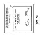
- screens 110 and 120( FIGS. 6A and 6B ) will be used. As seen in FIG. 6A , these adjustments are most useful for low-rate, wide pulse width stimulation (such as CIS and MPS stimulation strategies). These screens are used to set the threshold iso-loudness contour T using a “buzz” or “hum” or similar as feedback.
- the patientis instructed to “Increase volume until you just begin to hear a ‘hum’ or ‘buzz’” or the like.
- the patientmay adjust the volume in various ways, such as with knob 112 . When the patient is satisfied, they may choose Next button 114 to proceed to screen 120 . The patient is then instructed “If you still hear a “buzz,” reduce volume until buzz just disappears.” The volume is again adjusted with knob 116 or equivalent. When the patient is satisfied, they may choose the Next button 118 .
- the Next button 118may take the patient to a “fitting completed” screen, where the patient may have the option to repeat part or all of the fitting process.
- screens 110 and 120may repeat a given or optional number of times.
- the earlier completed proceduresmay be retained or saved, and possibly used as starting points for subsequent fitting procedures.
- results from multiple fitting proceduresmay be combined, as appropriate, to arrive at the values used by the cochlear implant.
- the above procedure for determining the T iso-loudness contourmay be performed on a single channel. Once the difference between the M and T levels for that one channel is known, the earlier-determined M iso-loudness curve is shifted the amount of that difference and set as the T contour. In other words, it is proposed that the T iso-loudness contour follows the same iso-curve as the M iso-loudness contour. As a result, the M curve need only be shifted to a lower level by the appropriate amount, which may be determined by measuring the difference between the M and T level at one channel. Of course, if desired, the T level may be measured at more than one channel, and the software may allow the user to determine which channel(s) to measure.
- T iso-loudness contourslower level T iso-loudness contours
- the patient's performancepotentially improves.
- the T contourmay be set to zero or some low value.
- the M iso-loudness contourmay be linearly transposed to a lower level in order to obtain the T iso-loudness contour.
- the M iso-loudness contourmay be obtained as taught above, or by other methods. For instance, NRI (neural response imaging) or EABR (evoked auditory brainstem response) may be used to obtain an iso-neural contour.
- NRIneural response imaging
- EABRevoked auditory brainstem response
- iso-neural response curvesmay appear at any level.
- the iso-neural curveneed only be linearly transposed to the M level and, if needed or desired, to the T level (each measured, for instance, on only one or few channels).
- the M iso-loudness curve(and potentially the T curve as well) can be predicted by an iso-neural curve, such as from NRI or EABR, since they follow the same iso-curve.
- the M iso-loudness curveis known—psychophysically determined as with the method above, or predicted with an iso-neural curve—the T iso-loudness curve can be predicted, since, at least for some stimulation strategies, they follow the same iso-curve. Therefore, in any of these cases, the different levels of the curves need only be determined with a single channel (although more than one may also be used), and the difference used as the amount and direction of linear transposition.
- the relative shape of the upper level iso-loudness contourmay also or instead be determined at a wider pulse width. For instance, contours determined with pulse widths of about 30 ⁇ s or about 35 ⁇ s or even about 75 ⁇ s may be used to predict the contours at about 10 ⁇ s or about 20 ⁇ s. The iso-curves so determined may then be linearly scaled, if needed (e.g., due to channel summation), to give the patient the appropriate volume.
- the present inventionprovides, inter alia, for SAS and High Rate stimulation strategies, that only one contour is required and can be obtained with NRI, EABR, or by a psychophysically determined loudness-balancing task.
- a threshold settingsuch as CIS, MPS, and other low rate, wide pulse width stimulation strategies
- iso-contoursare much easier to obtain than maximal comfort levels or threshold levels.
Landscapes
- Health & Medical Sciences (AREA)
- Otolaryngology (AREA)
- Engineering & Computer Science (AREA)
- Biomedical Technology (AREA)
- Nuclear Medicine, Radiotherapy & Molecular Imaging (AREA)
- Radiology & Medical Imaging (AREA)
- Life Sciences & Earth Sciences (AREA)
- Animal Behavior & Ethology (AREA)
- General Health & Medical Sciences (AREA)
- Public Health (AREA)
- Veterinary Medicine (AREA)
- Prostheses (AREA)
Abstract
Description
- 1) patient self-programming (a.k.a., self-fitting),
- 2) fitting without determination of T-levels, and
- 3) fitting without patient feedback (a.k.a., auto-fitting).
These improvements are possible via, inter alia, the simplicity of the programming graphical user interface (GUI) provided by the present invention. For example, such a program could be placed on a handheld computer and the patient could setup the basic programming parameters prior to seeing their audiologist. Also, with the use of neural response imaging (NRI) strategies or the like, fitting becomes automatic, or at least comes closer to being automatic.
Claims (20)
Priority Applications (1)
| Application Number | Priority Date | Filing Date | Title |
|---|---|---|---|
| US10/647,372US7043303B1 (en) | 2002-08-30 | 2003-08-25 | Enhanced methods for determining iso-loudness contours for fitting cochlear implant sound processors |
Applications Claiming Priority (2)
| Application Number | Priority Date | Filing Date | Title |
|---|---|---|---|
| US40726302P | 2002-08-30 | 2002-08-30 | |
| US10/647,372US7043303B1 (en) | 2002-08-30 | 2003-08-25 | Enhanced methods for determining iso-loudness contours for fitting cochlear implant sound processors |
Publications (1)
| Publication Number | Publication Date |
|---|---|
| US7043303B1true US7043303B1 (en) | 2006-05-09 |
Family
ID=36272397
Family Applications (1)
| Application Number | Title | Priority Date | Filing Date |
|---|---|---|---|
| US10/647,372Expired - Fee RelatedUS7043303B1 (en) | 2002-08-30 | 2003-08-25 | Enhanced methods for determining iso-loudness contours for fitting cochlear implant sound processors |
Country Status (1)
| Country | Link |
|---|---|
| US (1) | US7043303B1 (en) |
Cited By (37)
| Publication number | Priority date | Publication date | Assignee | Title |
|---|---|---|---|---|
| US20050008177A1 (en)* | 2003-07-11 | 2005-01-13 | Ibrahim Ibrahim | Audio path diagnostics |
| US20060029912A1 (en)* | 2004-06-12 | 2006-02-09 | Neuro Tone, Inc. | Aural rehabilitation system and a method of using the same |
| US20060235332A1 (en)* | 2002-06-26 | 2006-10-19 | Smoorenburg Guido F | Parametric fitting of a cochlear implant |
| US20060271114A1 (en)* | 2001-12-26 | 2006-11-30 | Voelkel Andrew W | Stimulation channel selection methods |
| US20070135862A1 (en)* | 2005-12-08 | 2007-06-14 | Cochlear Limited | Multimodal auditory fitting |
| US20070255344A1 (en)* | 2006-04-21 | 2007-11-01 | Cochlear Limited | Determining operating parameters for a stimulating medical device |
| US20070260292A1 (en)* | 2006-05-05 | 2007-11-08 | Faltys Michael A | Information processing and storage in a cochlear stimulation system |
| US20080009914A1 (en)* | 2006-07-10 | 2008-01-10 | Ams Research Corporation | Systems and Methods for Implanting Tissue Stimulation Electrodes in the Pelvic Region |
| US20080021551A1 (en)* | 2002-12-11 | 2008-01-24 | Advanced Bionics Corporation | Optimizing pitch and other speech stimuli allocation in a cochlear implant |
| US20080085023A1 (en)* | 2006-09-25 | 2008-04-10 | Abhijit Kulkarni | Auditory Front End Customization |
| US20080195179A1 (en)* | 2006-07-17 | 2008-08-14 | Advanced Bionics Corporation | Systems and methods for determining a threshold current level required to evoke a stapedial muscle reflex |
| US20080319508A1 (en)* | 2004-06-15 | 2008-12-25 | Cochlear Americas | Automatic Determination of the Threshold of an Evoked Neural Response |
| US20090018616A1 (en)* | 2006-07-17 | 2009-01-15 | Advanced Bionics, Llc | Systems and Methods for Determining a Threshold Current Level Required to Evoke a Stapedial Muscle Reflex |
| US20090132006A1 (en)* | 2007-07-13 | 2009-05-21 | Cochlear Limited | Using interaction to measure neural excitation |
| US20090222064A1 (en)* | 2005-07-08 | 2009-09-03 | Advanced Bionics, Llc | Autonomous Autoprogram Cochlear Implant |
| US20090264962A1 (en)* | 2004-04-02 | 2009-10-22 | Faltys Michael A | Electric and Acoustic Stimulation Fitting Systems and Methods |
| US20100046779A1 (en)* | 2003-05-08 | 2010-02-25 | Crawford Scott A | Modular speech processor headpiece |
| US20100046778A1 (en)* | 2003-05-08 | 2010-02-25 | Crawford Scott A | Integrated cochlear implant headpiece |
| US20100292751A1 (en)* | 2009-05-12 | 2010-11-18 | National Chiao Tung University | Parameter adjustment device and method thereof |
| US20110015700A1 (en)* | 2005-10-31 | 2011-01-20 | Dijk Bastiaan Van | Provision of stimulus components having variable perceptability to stimulating device recipient |
| US20110060385A1 (en)* | 2009-09-10 | 2011-03-10 | Lineaweaver Sean K | Determining stimulation level parameters in implant fitting |
| US20110082521A1 (en)* | 2004-06-15 | 2011-04-07 | Andrew Botros | Automatic measurement of an evoked neural response concurrent with an indication of a psychophysics reaction |
| US7933657B1 (en) | 2002-08-30 | 2011-04-26 | Advanced Bionics, Llc | System and method for fitting a cochlear implant sound processor using alternative signals |
| WO2011033435A3 (en)* | 2009-09-10 | 2011-08-04 | Cochlear Limited | Determining stimulation level parameters in implant fitting |
| US7995771B1 (en) | 2006-09-25 | 2011-08-09 | Advanced Bionics, Llc | Beamforming microphone system |
| US8107661B1 (en) | 2003-05-08 | 2012-01-31 | Advanced Bionics, Llc | Listening device cap |
| US8165689B1 (en)* | 2008-04-09 | 2012-04-24 | Advanced Bionics, Llc | Methods and systems of compensating for a disabled electrode |
| US8260430B2 (en) | 2010-07-01 | 2012-09-04 | Cochlear Limited | Stimulation channel selection for a stimulating medical device |
| US20130023965A1 (en)* | 2007-11-30 | 2013-01-24 | Lockheed Martin Corporation | Optimized stimulation rate of an optically stimulating cochlear implant |
| EP2716071A1 (en)* | 2011-05-26 | 2014-04-09 | Advanced Bionics AG | Methods and systems for facilitating adjustment of one or more fitting parameters by an auditory prosthesis patient |
| US8700168B1 (en)* | 2010-07-30 | 2014-04-15 | Advanced Bionics Ag | Systems and methods for providing a pre-stimulation visual cue representative of a cochlear implant stimulation level |
| US20140140523A1 (en)* | 2012-08-14 | 2014-05-22 | Zachary M. Smith | Fitting Bilateral Hearing Prostheses |
| US20160140873A1 (en)* | 2014-11-18 | 2016-05-19 | Cochlear Limited | Hearing prosthesis efficacy altering and/or forecasting techniques |
| US20170252570A1 (en)* | 2016-03-07 | 2017-09-07 | Boston Scientific Neuromodulation Corporation | Systems and methods for communication during remote programming |
| WO2018160450A1 (en)* | 2017-02-28 | 2018-09-07 | Med-El Elektromedizinische Geraete Gmbh | Fast objective fitting measurements for cochlear implants |
| US11253193B2 (en) | 2016-11-08 | 2022-02-22 | Cochlear Limited | Utilization of vocal acoustic biomarkers for assistive listening device utilization |
| US11607546B2 (en)* | 2017-02-01 | 2023-03-21 | The Trustees Of Indiana University | Cochlear implant |
Citations (22)
| Publication number | Priority date | Publication date | Assignee | Title |
|---|---|---|---|---|
| US3751605A (en) | 1972-02-04 | 1973-08-07 | Beckman Instruments Inc | Method for inducing hearing |
| US4400590A (en) | 1980-12-22 | 1983-08-23 | The Regents Of The University Of California | Apparatus for multichannel cochlear implant hearing aid system |
| US4495384A (en) | 1982-08-23 | 1985-01-22 | Scott Instruments Corporation | Real time cochlear implant processor |
| US4819647A (en) | 1984-05-03 | 1989-04-11 | The Regents Of The University Of California | Intracochlear electrode array |
| US5597380A (en)* | 1991-07-02 | 1997-01-28 | Cochlear Ltd. | Spectral maxima sound processor |
| US5603726A (en) | 1989-09-22 | 1997-02-18 | Alfred E. Mann Foundation For Scientific Research | Multichannel cochlear implant system including wearable speech processor |
| US5626629A (en) | 1995-05-31 | 1997-05-06 | Advanced Bionics Corporation | Programming of a speech processor for an implantable cochlear stimulator |
| US5938691A (en) | 1989-09-22 | 1999-08-17 | Alfred E. Mann Foundation | Multichannel implantable cochlear stimulator |
| US6067474A (en) | 1997-08-01 | 2000-05-23 | Advanced Bionics Corporation | Implantable device with improved battery recharging and powering configuration |
| US6078838A (en) | 1998-02-13 | 2000-06-20 | University Of Iowa Research Foundation | Pseudospontaneous neural stimulation system and method |
| US6129753A (en) | 1998-03-27 | 2000-10-10 | Advanced Bionics Corporation | Cochlear electrode array with electrode contacts on medial side |
| US6157861A (en)* | 1996-06-20 | 2000-12-05 | Advanced Bionics Corporation | Self-adjusting cochlear implant system and method for fitting same |
| US6195585B1 (en) | 1998-06-26 | 2001-02-27 | Advanced Bionics Corporation | Remote monitoring of implantable cochlear stimulator |
| US6205360B1 (en)* | 1995-09-07 | 2001-03-20 | Cochlear Limited | Apparatus and method for automatically determining stimulation parameters |
| US6208882B1 (en) | 1998-06-03 | 2001-03-27 | Advanced Bionics Corporation | Stapedius reflex electrode and connector |
| US6219580B1 (en) | 1995-04-26 | 2001-04-17 | Advanced Bionics Corporation | Multichannel cochlear prosthesis with flexible control of stimulus waveforms |
| US6249704B1 (en) | 1998-08-11 | 2001-06-19 | Advanced Bionics Corporation | Low voltage stimulation to elicit stochastic response patterns that enhance the effectiveness of a cochlear implant |
| US6289247B1 (en) | 1998-06-02 | 2001-09-11 | Advanced Bionics Corporation | Strategy selector for multichannel cochlear prosthesis |
| US6295467B1 (en) | 1996-07-18 | 2001-09-25 | Birger Kollmeier | Method and device for detecting a reflex of the human stapedius muscle |
| US6415185B1 (en) | 1998-09-04 | 2002-07-02 | Advanced Bionics Corporation | Objective programming and operation of a Cochlear implant based on measured evoked potentials that precede the stapedius reflex |
| WO2003015863A2 (en) | 2001-08-17 | 2003-02-27 | Advanced Bionics Corporation | Gradual recruitment of muscle/neural excitable tissue using high-rate electrical stimulation parameters |
| US6778858B1 (en)* | 1999-09-16 | 2004-08-17 | Advanced Bionics N.V. | Cochlear implant |
- 2003
- 2003-08-25USUS10/647,372patent/US7043303B1/ennot_activeExpired - Fee Related
Patent Citations (22)
| Publication number | Priority date | Publication date | Assignee | Title |
|---|---|---|---|---|
| US3751605A (en) | 1972-02-04 | 1973-08-07 | Beckman Instruments Inc | Method for inducing hearing |
| US4400590A (en) | 1980-12-22 | 1983-08-23 | The Regents Of The University Of California | Apparatus for multichannel cochlear implant hearing aid system |
| US4495384A (en) | 1982-08-23 | 1985-01-22 | Scott Instruments Corporation | Real time cochlear implant processor |
| US4819647A (en) | 1984-05-03 | 1989-04-11 | The Regents Of The University Of California | Intracochlear electrode array |
| US5938691A (en) | 1989-09-22 | 1999-08-17 | Alfred E. Mann Foundation | Multichannel implantable cochlear stimulator |
| US5603726A (en) | 1989-09-22 | 1997-02-18 | Alfred E. Mann Foundation For Scientific Research | Multichannel cochlear implant system including wearable speech processor |
| US5597380A (en)* | 1991-07-02 | 1997-01-28 | Cochlear Ltd. | Spectral maxima sound processor |
| US6219580B1 (en) | 1995-04-26 | 2001-04-17 | Advanced Bionics Corporation | Multichannel cochlear prosthesis with flexible control of stimulus waveforms |
| US5626629A (en) | 1995-05-31 | 1997-05-06 | Advanced Bionics Corporation | Programming of a speech processor for an implantable cochlear stimulator |
| US6205360B1 (en)* | 1995-09-07 | 2001-03-20 | Cochlear Limited | Apparatus and method for automatically determining stimulation parameters |
| US6157861A (en)* | 1996-06-20 | 2000-12-05 | Advanced Bionics Corporation | Self-adjusting cochlear implant system and method for fitting same |
| US6295467B1 (en) | 1996-07-18 | 2001-09-25 | Birger Kollmeier | Method and device for detecting a reflex of the human stapedius muscle |
| US6067474A (en) | 1997-08-01 | 2000-05-23 | Advanced Bionics Corporation | Implantable device with improved battery recharging and powering configuration |
| US6078838A (en) | 1998-02-13 | 2000-06-20 | University Of Iowa Research Foundation | Pseudospontaneous neural stimulation system and method |
| US6129753A (en) | 1998-03-27 | 2000-10-10 | Advanced Bionics Corporation | Cochlear electrode array with electrode contacts on medial side |
| US6289247B1 (en) | 1998-06-02 | 2001-09-11 | Advanced Bionics Corporation | Strategy selector for multichannel cochlear prosthesis |
| US6208882B1 (en) | 1998-06-03 | 2001-03-27 | Advanced Bionics Corporation | Stapedius reflex electrode and connector |
| US6195585B1 (en) | 1998-06-26 | 2001-02-27 | Advanced Bionics Corporation | Remote monitoring of implantable cochlear stimulator |
| US6249704B1 (en) | 1998-08-11 | 2001-06-19 | Advanced Bionics Corporation | Low voltage stimulation to elicit stochastic response patterns that enhance the effectiveness of a cochlear implant |
| US6415185B1 (en) | 1998-09-04 | 2002-07-02 | Advanced Bionics Corporation | Objective programming and operation of a Cochlear implant based on measured evoked potentials that precede the stapedius reflex |
| US6778858B1 (en)* | 1999-09-16 | 2004-08-17 | Advanced Bionics N.V. | Cochlear implant |
| WO2003015863A2 (en) | 2001-08-17 | 2003-02-27 | Advanced Bionics Corporation | Gradual recruitment of muscle/neural excitable tissue using high-rate electrical stimulation parameters |
Non-Patent Citations (8)
| Title |
|---|
| Faltys inventor for AB-257U; U.S. Appl. No. 10/218,616; filed Aug. 13, 2002; entitled "Bionic Ear Programming System". |
| Overstreet and Faltys inventors for AB-254U; U.S. Appl. No. 10/218,645; filed Aug. 13, 2002; entitled "Cochlear Implant and Simplified Method for Fitting Same". |
| Overstreet inventor for AB-379U; U.S. Appl. No. 10/698,098; filed Oct. 31, 2003; entitled "Method and System for Generating a Cochlear Implant Program Using Multi-Electrode Stimulation to Elicit the Electrically-Evoked Compound Action Potential". |
| Overstreet, Litvak, and Faltys inventors for AB-378U; U.S. Appl. No. 10/698,097; filed Oct. 31, 2003; entitled "Multi-Electrode Stimulation to Elicit Electrically-Evoked Compound Action Potential." |
| Rubinstein et al., "The Neurophysiological Effects of Simulated Auditory Prosthesis Simulation" Second Quarterly Progress Report NO1-DC-6-2111. |
| Segel, Overstreet, Kruger, and Mishra inventors for AB-313U; U.S. Appl. No. 10/651,653; filed Aug. 29, 2003; entitled System and Method for Fitting a Cochlear Implant Sound Processor Using Alternative Signals. |
| van Wieringen, et al., "Comparison of Procedures to Determine Electrical Stimulation Thresholds in Cochlear Implant Users", Ear and Hearing, vol. 22(6), (2001), pp. 528-538. |
| Zeng, et al., "Loudness of Simple and Complex Stimuli in Electric Hearing", Annals of Otology, Rhinology & Laryngology, vol. 104 (9), pp. 235-238. |
Cited By (114)
| Publication number | Priority date | Publication date | Assignee | Title |
|---|---|---|---|---|
| US7751900B2 (en) | 2001-12-26 | 2010-07-06 | Advanced Bionics, Llc | Stimulation channel selection methods |
| US7603175B2 (en) | 2001-12-26 | 2009-10-13 | Advanced Bionics, Llc | Stimulation channel selection methods |
| US7603176B2 (en) | 2001-12-26 | 2009-10-13 | Advanced Bionics, Llc | Stimulation channel selection methods |
| US20060271114A1 (en)* | 2001-12-26 | 2006-11-30 | Voelkel Andrew W | Stimulation channel selection methods |
| US20060271127A1 (en)* | 2001-12-26 | 2006-11-30 | Voelkel Andrew W | Stimulation channel selection methods |
| US20060271126A1 (en)* | 2001-12-26 | 2006-11-30 | Voelkel Andrew W | Stimulation channel selection methods |
| US20060271125A1 (en)* | 2001-12-26 | 2006-11-30 | Voelkel Andrew W | Systems for selecting one or more stimulation channels |
| US20060271113A1 (en)* | 2001-12-26 | 2006-11-30 | Voelkel Andrew W | Stimulation channel selection methods |
| US7599742B2 (en) | 2001-12-26 | 2009-10-06 | Advanced Bionics, Llc | Stimulation channel selection methods |
| US7697992B2 (en) | 2001-12-26 | 2010-04-13 | Advanced Bionics, Llc | Systems for selecting one or more stimulation channels |
| US8401656B2 (en) | 2002-06-26 | 2013-03-19 | Cochlear Limited | Perception-based parametric fitting of a prosthetic hearing device |
| US8694113B2 (en) | 2002-06-26 | 2014-04-08 | Cochlear Limited | Parametric fitting of a cochlear implant |
| US20060235332A1 (en)* | 2002-06-26 | 2006-10-19 | Smoorenburg Guido F | Parametric fitting of a cochlear implant |
| US20090043359A1 (en)* | 2002-06-26 | 2009-02-12 | Cochlear Limited | Perception-based parametric fitting of a prosthetic hearing device |
| US7933657B1 (en) | 2002-08-30 | 2011-04-26 | Advanced Bionics, Llc | System and method for fitting a cochlear implant sound processor using alternative signals |
| US8233989B1 (en) | 2002-08-30 | 2012-07-31 | Advanced Bionics, Llc | System and method for fitting a hearing prosthesis sound processor using alternative signals |
| US20080021551A1 (en)* | 2002-12-11 | 2008-01-24 | Advanced Bionics Corporation | Optimizing pitch and other speech stimuli allocation in a cochlear implant |
| US7805198B2 (en) | 2002-12-11 | 2010-09-28 | Advanced Bionics, Llc | Optimizing pitch and other speech stimuli allocation in a cochlear implant |
| US7920925B2 (en) | 2002-12-11 | 2011-04-05 | Advanced Bionics, Llc | Optimizing pitch and other speech stimuli allocation in a cochlear implant |
| US10531207B2 (en) | 2003-05-08 | 2020-01-07 | Advanced Bionics Ag | Speech processor headpiece |
| US11583677B2 (en) | 2003-05-08 | 2023-02-21 | Advanced Bionics Ag | Cochlear implant headpiece |
| US9674620B2 (en) | 2003-05-08 | 2017-06-06 | Advanced Bionics Ag | Speech processor headpiece |
| US8170253B1 (en) | 2003-05-08 | 2012-05-01 | Advanced Bionics | Listening device cap |
| US10200798B2 (en) | 2003-05-08 | 2019-02-05 | Advanced Bionics Ag | Cochlear implant headpiece |
| US8107661B1 (en) | 2003-05-08 | 2012-01-31 | Advanced Bionics, Llc | Listening device cap |
| US8270647B2 (en) | 2003-05-08 | 2012-09-18 | Advanced Bionics, Llc | Modular speech processor headpiece |
| US9392384B2 (en) | 2003-05-08 | 2016-07-12 | Advanced Bionics Ag | Integrated speech processor headpiece |
| US20100046779A1 (en)* | 2003-05-08 | 2010-02-25 | Crawford Scott A | Modular speech processor headpiece |
| US20100046778A1 (en)* | 2003-05-08 | 2010-02-25 | Crawford Scott A | Integrated cochlear implant headpiece |
| US11318308B2 (en) | 2003-05-08 | 2022-05-03 | Advanced Bionics Ag | Speech processor headpiece |
| US8515112B2 (en) | 2003-05-08 | 2013-08-20 | Advanced Bionics, Llc | Modular speech processor headpiece |
| US10462588B2 (en) | 2003-05-08 | 2019-10-29 | Advanced Bionics Ag | Speech processor headpiece |
| US8983102B2 (en) | 2003-05-08 | 2015-03-17 | Advanced Bionics Ag | Speech processor headpiece |
| US10960208B2 (en) | 2003-05-08 | 2021-03-30 | Advanced Bionics Ag | Cochlear implant headpiece |
| US8811643B2 (en) | 2003-05-08 | 2014-08-19 | Advanced Bionics | Integrated cochlear implant headpiece |
| US8223982B2 (en)* | 2003-07-11 | 2012-07-17 | Cochlear Limited | Audio path diagnostics |
| US20050008177A1 (en)* | 2003-07-11 | 2005-01-13 | Ibrahim Ibrahim | Audio path diagnostics |
| US20090264963A1 (en)* | 2004-04-02 | 2009-10-22 | Faltys Michael A | Electric and Acoustic Stimulation Fitting Systems and Methods |
| US8155747B2 (en) | 2004-04-02 | 2012-04-10 | Advanced Bionics, Llc | Electric and acoustic stimulation fitting systems and methods |
| US8150527B2 (en) | 2004-04-02 | 2012-04-03 | Advanced Bionics, Llc | Electric and acoustic stimulation fitting systems and methods |
| US20090264962A1 (en)* | 2004-04-02 | 2009-10-22 | Faltys Michael A | Electric and Acoustic Stimulation Fitting Systems and Methods |
| US20060029912A1 (en)* | 2004-06-12 | 2006-02-09 | Neuro Tone, Inc. | Aural rehabilitation system and a method of using the same |
| US10449357B2 (en) | 2004-06-15 | 2019-10-22 | Cochlear Limited | Automatic determination of the threshold of an evoked neural response |
| US20080319508A1 (en)* | 2004-06-15 | 2008-12-25 | Cochlear Americas | Automatic Determination of the Threshold of an Evoked Neural Response |
| US20110082521A1 (en)* | 2004-06-15 | 2011-04-07 | Andrew Botros | Automatic measurement of an evoked neural response concurrent with an indication of a psychophysics reaction |
| US8965520B2 (en) | 2004-06-15 | 2015-02-24 | Cochlear Limited | Automatic determination of the threshold of an evoked neural response |
| US9744356B2 (en) | 2004-06-15 | 2017-08-29 | Cochlear Limited | Automatic determination of the threshold of an evoked neural response |
| US8190268B2 (en) | 2004-06-15 | 2012-05-29 | Cochlear Limited | Automatic measurement of an evoked neural response concurrent with an indication of a psychophysics reaction |
| US20090222064A1 (en)* | 2005-07-08 | 2009-09-03 | Advanced Bionics, Llc | Autonomous Autoprogram Cochlear Implant |
| US8019432B2 (en) | 2005-10-31 | 2011-09-13 | Cochlear Limited | Provision of stimulus components having variable perceptability to stimulating device recipient |
| US20110015700A1 (en)* | 2005-10-31 | 2011-01-20 | Dijk Bastiaan Van | Provision of stimulus components having variable perceptability to stimulating device recipient |
| US8265765B2 (en) | 2005-12-08 | 2012-09-11 | Cochlear Limited | Multimodal auditory fitting |
| US20070135862A1 (en)* | 2005-12-08 | 2007-06-14 | Cochlear Limited | Multimodal auditory fitting |
| US8571674B2 (en) | 2005-12-08 | 2013-10-29 | Cochlear Limited | Multimodal auditory fitting |
| US20070255344A1 (en)* | 2006-04-21 | 2007-11-01 | Cochlear Limited | Determining operating parameters for a stimulating medical device |
| US8571675B2 (en) | 2006-04-21 | 2013-10-29 | Cochlear Limited | Determining operating parameters for a stimulating medical device |
| US9855425B2 (en) | 2006-05-05 | 2018-01-02 | Advanced Bionics Ag | Information processing and storage in a cochlear stimulation system |
| US20070260292A1 (en)* | 2006-05-05 | 2007-11-08 | Faltys Michael A | Information processing and storage in a cochlear stimulation system |
| US8818517B2 (en) | 2006-05-05 | 2014-08-26 | Advanced Bionics Ag | Information processing and storage in a cochlear stimulation system |
| US20080009914A1 (en)* | 2006-07-10 | 2008-01-10 | Ams Research Corporation | Systems and Methods for Implanting Tissue Stimulation Electrodes in the Pelvic Region |
| US20080195179A1 (en)* | 2006-07-17 | 2008-08-14 | Advanced Bionics Corporation | Systems and methods for determining a threshold current level required to evoke a stapedial muscle reflex |
| US20090018616A1 (en)* | 2006-07-17 | 2009-01-15 | Advanced Bionics, Llc | Systems and Methods for Determining a Threshold Current Level Required to Evoke a Stapedial Muscle Reflex |
| US7925355B2 (en) | 2006-07-17 | 2011-04-12 | Advanced Bionics, Llc | Systems and methods for determining a threshold current level required to evoke a stapedial muscle reflex |
| US8103354B2 (en) | 2006-07-17 | 2012-01-24 | Advanced Bionics, Llc | Systems and methods for determining a threshold current level required to evoke a stapedial muscle reflex |
| US20110069853A1 (en)* | 2006-09-25 | 2011-03-24 | Advanced Bionics, Llc | Auditory Front End Customization |
| US9668068B2 (en) | 2006-09-25 | 2017-05-30 | Advanced Bionics, Llc | Beamforming microphone system |
| US7864968B2 (en) | 2006-09-25 | 2011-01-04 | Advanced Bionics, Llc | Auditory front end customization |
| US8503685B2 (en) | 2006-09-25 | 2013-08-06 | Advanced Bionics Ag | Auditory front end customization |
| US20080085023A1 (en)* | 2006-09-25 | 2008-04-10 | Abhijit Kulkarni | Auditory Front End Customization |
| US7995771B1 (en) | 2006-09-25 | 2011-08-09 | Advanced Bionics, Llc | Beamforming microphone system |
| US8996127B2 (en) | 2007-07-13 | 2015-03-31 | Cochlear Limited | Using interaction to measure neural excitation |
| US8391993B2 (en) | 2007-07-13 | 2013-03-05 | Cochlear Limited | Using interaction to measure neural excitation |
| US20090132005A1 (en)* | 2007-07-13 | 2009-05-21 | Cochlear Limited | Assessing neural survival |
| US8880180B2 (en)* | 2007-07-13 | 2014-11-04 | Cochlear Limited | Assessing neural survival |
| WO2009010870A3 (en)* | 2007-07-13 | 2009-12-30 | Cochlear Limited | Using interaction to measure neural excitation |
| US20090132006A1 (en)* | 2007-07-13 | 2009-05-21 | Cochlear Limited | Using interaction to measure neural excitation |
| US20130023960A1 (en)* | 2007-11-30 | 2013-01-24 | Lockheed Martin Corporation | Broad wavelength profile to homogenize the absorption profile in optical stimulation of nerves |
| US20130023965A1 (en)* | 2007-11-30 | 2013-01-24 | Lockheed Martin Corporation | Optimized stimulation rate of an optically stimulating cochlear implant |
| US8998914B2 (en)* | 2007-11-30 | 2015-04-07 | Lockheed Martin Corporation | Optimized stimulation rate of an optically stimulating cochlear implant |
| US9011508B2 (en)* | 2007-11-30 | 2015-04-21 | Lockheed Martin Corporation | Broad wavelength profile to homogenize the absorption profile in optical stimulation of nerves |
| US8768476B2 (en)* | 2008-04-09 | 2014-07-01 | Advanced Bionics, Llc | Methods and systems of compensating for a disabled electrode |
| US8165689B1 (en)* | 2008-04-09 | 2012-04-24 | Advanced Bionics, Llc | Methods and systems of compensating for a disabled electrode |
| US20120179223A1 (en)* | 2008-04-09 | 2012-07-12 | Advanced Bionics, Llc | Methods and systems of compensating for a disabled electrode |
| US8666503B2 (en)* | 2009-05-12 | 2014-03-04 | National Chiao Tung University | Parameter adjustment device and method thereof |
| TWI397789B (en)* | 2009-05-12 | 2013-06-01 | Univ Nat Chiao Tung | Parameter adjusting device and method thereof |
| US20100292751A1 (en)* | 2009-05-12 | 2010-11-18 | National Chiao Tung University | Parameter adjustment device and method thereof |
| EP2475344A4 (en)* | 2009-09-10 | 2013-06-12 | Cochlear Ltd | Determining stimulation level parameters in implant fitting |
| US20110060385A1 (en)* | 2009-09-10 | 2011-03-10 | Lineaweaver Sean K | Determining stimulation level parameters in implant fitting |
| CN102612354A (en)* | 2009-09-10 | 2012-07-25 | 耳蜗有限公司 | Determining stimulation level parameters in implant fitting |
| CN102612354B (en)* | 2009-09-10 | 2015-09-02 | 耳蜗有限公司 | Determining stimulation level parameters in implant deployment |
| WO2011033435A3 (en)* | 2009-09-10 | 2011-08-04 | Cochlear Limited | Determining stimulation level parameters in implant fitting |
| US8260430B2 (en) | 2010-07-01 | 2012-09-04 | Cochlear Limited | Stimulation channel selection for a stimulating medical device |
| US8700168B1 (en)* | 2010-07-30 | 2014-04-15 | Advanced Bionics Ag | Systems and methods for providing a pre-stimulation visual cue representative of a cochlear implant stimulation level |
| US8923979B1 (en) | 2010-07-30 | 2014-12-30 | Advanced Bionics Ag | Systems and methods for providing a pre-stimulation visual cue representative of a cochlear implant stimulation level |
| EP2716071A1 (en)* | 2011-05-26 | 2014-04-09 | Advanced Bionics AG | Methods and systems for facilitating adjustment of one or more fitting parameters by an auditory prosthesis patient |
| US9050465B2 (en)* | 2011-05-26 | 2015-06-09 | Advanced Bionics Ag | Methods and systems for facilitating adjustment of one or more fitting parameters by an auditory prosthesis patient |
| US20140114375A1 (en)* | 2011-05-26 | 2014-04-24 | Advanced Bionics Ag | Methods and systems for facilitating adjustment of one or more fitting parameters by an auditory prosthesis patient |
| US8840654B2 (en)* | 2011-07-22 | 2014-09-23 | Lockheed Martin Corporation | Cochlear implant using optical stimulation with encoded information designed to limit heating effects |
| US20130023963A1 (en)* | 2011-07-22 | 2013-01-24 | Lockheed Martin Corporation | Cochlear implant using optical stimulation with encoded information designed to limit heating effects |
| US9630009B2 (en) | 2012-08-14 | 2017-04-25 | Cochlear Limited | Fitting bilateral hearing prostheses |
| US10052480B2 (en) | 2012-08-14 | 2018-08-21 | Cochlear Limited | Fitting bilateral hearing prostheses |
| US10994127B2 (en) | 2012-08-14 | 2021-05-04 | Cochlear Limited | Fitting bilateral hearing prostheses |
| US9232327B2 (en)* | 2012-08-14 | 2016-01-05 | Cochlear Limited | Fitting bilateral hearing prostheses |
| US20140140523A1 (en)* | 2012-08-14 | 2014-05-22 | Zachary M. Smith | Fitting Bilateral Hearing Prostheses |
| US10123725B2 (en)* | 2014-11-18 | 2018-11-13 | Cochlear Limited | Hearing prosthesis efficacy altering and/or forecasting techniques |
| US10863930B2 (en) | 2014-11-18 | 2020-12-15 | Cochlear Limited | Hearing prosthesis efficacy altering and/or forecasting techniques |
| US20160140873A1 (en)* | 2014-11-18 | 2016-05-19 | Cochlear Limited | Hearing prosthesis efficacy altering and/or forecasting techniques |
| US20170252570A1 (en)* | 2016-03-07 | 2017-09-07 | Boston Scientific Neuromodulation Corporation | Systems and methods for communication during remote programming |
| US11253193B2 (en) | 2016-11-08 | 2022-02-22 | Cochlear Limited | Utilization of vocal acoustic biomarkers for assistive listening device utilization |
| US20220240842A1 (en)* | 2016-11-08 | 2022-08-04 | Kieran REED | Utilization of vocal acoustic biomarkers for assistive listening device utilization |
| US11607546B2 (en)* | 2017-02-01 | 2023-03-21 | The Trustees Of Indiana University | Cochlear implant |
| AU2018229201B2 (en)* | 2017-02-28 | 2020-04-02 | Med-El Elektromedizinische Geraete Gmbh | Fast objective fitting measurements for cochlear implants |
| WO2018160450A1 (en)* | 2017-02-28 | 2018-09-07 | Med-El Elektromedizinische Geraete Gmbh | Fast objective fitting measurements for cochlear implants |
| US11077302B2 (en) | 2017-02-28 | 2021-08-03 | Med-El Elektromedizinische Geraete Gmbh | Fast objective fitting measurements for cochlear implants |
Similar Documents
| Publication | Publication Date | Title |
|---|---|---|
| US7043303B1 (en) | Enhanced methods for determining iso-loudness contours for fitting cochlear implant sound processors | |
| US8150527B2 (en) | Electric and acoustic stimulation fitting systems and methods | |
| US5626629A (en) | Programming of a speech processor for an implantable cochlear stimulator | |
| US6289247B1 (en) | Strategy selector for multichannel cochlear prosthesis | |
| US7206640B1 (en) | Method and system for generating a cochlear implant program using multi-electrode stimulation to elicit the electrically-evoked compound action potential | |
| US7103417B1 (en) | Adaptive place-pitch ranking procedure for optimizing performance of a multi-channel neural stimulator | |
| US8180455B2 (en) | Optimizing pitch allocation in a cochlear implant | |
| US7251530B1 (en) | Optimizing pitch and other speech stimuli allocation in a cochlear implant | |
| US8024046B2 (en) | Systems for fitting a cochlear implant to a patient | |
| JP5758306B2 (en) | Method and apparatus for adjusting a stimulating medical device having a multi-electrode channel configuration | |
| US5601617A (en) | Multichannel cochlear prosthesis with flexible control of stimulus waveforms | |
| US7574265B1 (en) | Cochlear implant and simplified method for fitting same | |
| US20080221640A1 (en) | Multi-electrode stimulation to elicit electrically-evoked compound action potential | |
| US7117038B1 (en) | Method and system for obtaining stapedial reflexes in cochlear implant users using multiband stimuli | |
| US7908012B2 (en) | Cochlear implant fitting system | |
| WO2004070561A9 (en) | Methods for programming a neural prosthesis | |
| US8233989B1 (en) | System and method for fitting a hearing prosthesis sound processor using alternative signals | |
| US7107101B1 (en) | Bionic ear programming system |
Legal Events
| Date | Code | Title | Description |
|---|---|---|---|
| AS | Assignment | Owner name:ADVANCED BIONICS CORPORATION, CALIFORNIA Free format text:ASSIGNMENT OF ASSIGNORS INTEREST;ASSIGNOR:OVERSTREET, EDWARD H.;REEL/FRAME:015117/0839 Effective date:20030823 | |
| AS | Assignment | Owner name:BOSTON SCIENTIFIC NEUROMODULATION CORPORATION, CAL Free format text:CHANGE OF NAME;ASSIGNOR:ADVANCED BIONICS CORPORATION;REEL/FRAME:020299/0200 Effective date:20071116 | |
| AS | Assignment | Owner name:BOSTON SCIENTIFIC NEUROMODULATION CORPORATION, CAL Free format text:CHANGE OF NAME;ASSIGNOR:ADVANCED BIONICS CORPORATION;REEL/FRAME:020309/0361 Effective date:20071116 | |
| AS | Assignment | Owner name:ADVANCED BIONICS, LLC, CALIFORNIA Free format text:ASSIGNMENT OF ASSIGNORS INTEREST;ASSIGNOR:BOSTON SCIENTIFIC NEUROMODULATION CORPORATION;REEL/FRAME:020340/0713 Effective date:20080107 Owner name:ADVANCED BIONICS, LLC,CALIFORNIA Free format text:ASSIGNMENT OF ASSIGNORS INTEREST;ASSIGNOR:BOSTON SCIENTIFIC NEUROMODULATION CORPORATION;REEL/FRAME:020340/0713 Effective date:20080107 | |
| FPAY | Fee payment | Year of fee payment:4 | |
| FPAY | Fee payment | Year of fee payment:8 | |
| FEPP | Fee payment procedure | Free format text:MAINTENANCE FEE REMINDER MAILED (ORIGINAL EVENT CODE: REM.) | |
| LAPS | Lapse for failure to pay maintenance fees | Free format text:PATENT EXPIRED FOR FAILURE TO PAY MAINTENANCE FEES (ORIGINAL EVENT CODE: EXP.) | |
| STCH | Information on status: patent discontinuation | Free format text:PATENT EXPIRED DUE TO NONPAYMENT OF MAINTENANCE FEES UNDER 37 CFR 1.362 | |
| FP | Lapsed due to failure to pay maintenance fee | Effective date:20180509 |