US7042664B2 - Method and system for host programmable data storage device self-testing - Google Patents
Method and system for host programmable data storage device self-testingDownload PDFInfo
- Publication number
- US7042664B2 US7042664B2US10/764,943US76494304AUS7042664B2US 7042664 B2US7042664 B2US 7042664B2US 76494304 AUS76494304 AUS 76494304AUS 7042664 B2US7042664 B2US 7042664B2
- Authority
- US
- United States
- Prior art keywords
- storage device
- data storage
- test
- memory
- data
- Prior art date
- Legal status (The legal status is an assumption and is not a legal conclusion. Google has not performed a legal analysis and makes no representation as to the accuracy of the status listed.)
- Expired - Lifetime, expires
Links
Images


Classifications
- G—PHYSICS
- G11—INFORMATION STORAGE
- G11B—INFORMATION STORAGE BASED ON RELATIVE MOVEMENT BETWEEN RECORD CARRIER AND TRANSDUCER
- G11B27/00—Editing; Indexing; Addressing; Timing or synchronising; Monitoring; Measuring tape travel
- G11B27/36—Monitoring, i.e. supervising the progress of recording or reproducing
- G—PHYSICS
- G11—INFORMATION STORAGE
- G11B—INFORMATION STORAGE BASED ON RELATIVE MOVEMENT BETWEEN RECORD CARRIER AND TRANSDUCER
- G11B5/00—Recording by magnetisation or demagnetisation of a record carrier; Reproducing by magnetic means; Record carriers therefor
- G11B5/02—Recording, reproducing, or erasing methods; Read, write or erase circuits therefor
- G—PHYSICS
- G11—INFORMATION STORAGE
- G11B—INFORMATION STORAGE BASED ON RELATIVE MOVEMENT BETWEEN RECORD CARRIER AND TRANSDUCER
- G11B5/00—Recording by magnetisation or demagnetisation of a record carrier; Reproducing by magnetic means; Record carriers therefor
- G11B2005/0002—Special dispositions or recording techniques
- G11B2005/0005—Arrangements, methods or circuits
- G11B2005/001—Controlling recording characteristics of record carriers or transducing characteristics of transducers by means not being part of their structure
- G—PHYSICS
- G11—INFORMATION STORAGE
- G11B—INFORMATION STORAGE BASED ON RELATIVE MOVEMENT BETWEEN RECORD CARRIER AND TRANSDUCER
- G11B2220/00—Record carriers by type
- G11B2220/20—Disc-shaped record carriers
Definitions
- This applicationrelates generally to data storage devices and more particularly to host programmable self-testing of a data storage device.
- a data storage devicesuch as a magnetic, optical, or magneto-optical drive includes a rotating storage medium.
- modem disc drivescomprise one or more rigid discs that are coated with a magnetizable medium and mounted on the hub of a spindle motor for rotation at a constant high speed.
- Informationis stored on the discs in a plurality of concentric circular tracks typically by an array of transducers (“heads”) mounted to a radial actuator for movement of the heads relative to the discs.
- headstransducers
- Each of the concentric tracksis generally divided into a plurality of separately addressable data sectors.
- the read/write transducere.g. a magnetoresistive read/write head
- the headsare mounted via flexures at the ends of a plurality of actuator arms that project radially outward from the actuator body.
- the actuator bodypivots about a shaft mounted to the disc drive housing at a position closely adjacent the outer extreme of the discs.
- the pivot shaftis parallel with the axis of rotation of the spindle motor and the discs, so that the heads move in a plane parallel with the surfaces of the discs.
- the actuator armis driven by a control signal fed to the voice coil motor (VCM) at the rear end of the actuator arm.
- VCMvoice coil motor
- a servo systemis used to sense the position of the actuator and control the movement of the head above the disc using servo signals read from a disc surface in the disc drive.
- the servo systemrelies on servo information stored on the disc.
- the signals from this informationgenerally indicate the present position of the head with respect to the disc, i.e., the current track position.
- the servo systemuses the sensed information to maintain head position or determine how to optimally move the head to a new position centered above a desired track.
- the servo systemthen delivers a control signal to the VCM to rotate the actuator to position the head over a desired new track or maintain the position over the desired current track.
- the present inventionprovides a solution to this and other problems, and offers other advantages over the prior art.
- a method of executing one or more self-tests on a data storage devicecomprises selecting one or more host programmable tests stored in memory in the data storage device by setting data in a first log in memory of the data storage device. Parameters for execution of the one or more host programmable tests are set in one or more values in a second log in memory of the data storage device. The one or more host programmable tests on the data storage device are then executed. Results of the one or more host programmable tests are stored in a third log in memory of the data storage device.
- a data storage devicecomprises one or more read/write heads, a storage medium accessible by the one or more read/write heads, a processor coupled with the read/write heads to access data on the storage medium, and a memory connected with and readable by the processor.
- the memoryhas stored therein one or more host programmable tests overwritten onto vendor specific portions of a self-monitoring program that are executable by the data storage device while the data storage device is connected with a host.
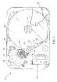
- FIG. 1is a plan view illustrating the primary internal components of a disc drive incorporating one of the various embodiments of the present invention.
- FIG. 2is a control block diagram for the disc drive shown in FIG. 1 illustrating the primary functional components.
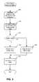
- FIG. 3is a flowchart illustrating data storage device self-testing according to one embodiment of the present invention.
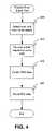
- FIG. 4is a flowchart illustrating a position error signal test that may be part of the self-test illustrated in FIG. 3 .
- FIG. 5is a flowchart illustrating a head error rate test that may be part of the self-test illustrated in FIG. 3 .
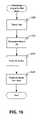
- FIG. 6is a flowchart illustrating a read verify reserve track data test that may be part of the self-test illustrated in FIG. 3 .
- FIG. 7is a flowchart illustrating a clear logs test that may be part of the self-test illustrated in FIG. 3
- FIG. 8is a flowchart illustrating an erase drive test that may be part of the self-test illustrated in FIG. 3 .
- FIG. 9is a flowchart illustrating a programmable drive write test that may be part of the self-test illustrated in FIG. 3 .
- FIG. 10is a flowchart illustrating executing host programmable tests according to one embodiment of the present invention.
- Embodiments of the present inventionwill be discussed with reference to a magnetic disc drive.
- One skilled in the artwill recognize that the present invention may also be applied to any data storage device, such as an optical disc drive, a magneto-optical disc drive, or other data storage device having multiple heads for accessing data on multiple storage media.
- FIG. 1is a plan view illustrating the primary internal components of a disc drive incorporating one of the various embodiments of the present invention.
- the disc drive 100includes a base 102 to which various components of the disc drive 100 are mounted.
- a top cover 104shown partially cut away, cooperates with the base 102 to form an internal, sealed environment for the disc drive in a conventional manner.
- the componentsinclude a spindle motor 106 which rotates one or more discs 108 at a constant high speed. Information is written to and read from tracks on the discs 108 through the use of an actuator assembly 110 , which rotates during a seek operation about a bearing shaft assembly 112 positioned adjacent the discs 108 .
- the actuator assembly 110includes a plurality of actuator arms 114 which extend towards the discs 108 , with one or more flexures 116 extending from each of the actuator arms 114 .
- a head 118mounted at the distal end of each of the flexures 116 is a head 118 which includes a fluid bearing slider enabling the head 118 to fly in close proximity above the corresponding surface of the associated disc 108 .
- the track position of the heads 118is controlled through the use of a voice coil motor (VCM) 124 , which typically includes a coil 126 attached to the actuator assembly 110 , as well as one or more permanent magnets 128 which establish a magnetic field in which the coil 126 is immersed.
- VCMvoice coil motor
- the controlled application of current to the coil 126causes magnetic interaction between the permanent magnets 128 and the coil 126 so that the coil 126 moves in accordance with the well-known Lorentz relationship.
- the actuator assembly 110pivots about the bearing shaft assembly 112 , and the heads 118 are caused to move across the surfaces of the discs 108 .
- the spindle motor 106is typically de-energized when the disc drive 100 is not in use for extended periods of time.
- the heads 118are moved away from portions of the disk 108 containing data when the drive motor is de-energized.
- the heads 118are secured over portions of the disk not containing data through the use of an actuator latch arrangement and/or ramp, which prevents inadvertent rotation of the actuator assembly 110 when the drive discs 108 are not spinning.
- a flex assembly 130provides the requisite electrical connection paths for the actuator assembly 110 while allowing pivotal movement of the actuator assembly 110 during operation.
- the flex assemblyincludes a printed circuit board 134 to which a flex cable leading to the head is connected; the flex cable leading to the heads 118 being routed along the actuator arms 114 and the flexures 116 to the heads 118 .
- the printed circuit board 132typically includes circuitry for controlling the write currents applied to the heads 118 during a write operation and a preamplifier for amplifying read signals generated by the heads 118 during a read operation.
- the flex assemblyterminates at a flex bracket 134 for communication through the base deck 102 to a disc drive printed circuit board (not shown) mounted to the bottom side of the disc drive 100 .
- FIG. 2is a control block diagram for a disc drive illustrating the primary functional components of a disc drive incorporating one of the various embodiments of the present invention and generally showing the main functional circuits which are resident on the disc drive printed circuit board and used to control the operation of the disc drive 100 .
- the disc drive 100is operably connected to a host computer 140 in a conventional manner. Control communication paths are provided between the host computer 140 and a disc drive microprocessor 142 , the microprocessor 142 generally providing top level communication and control for the disc drive 100 in conjunction with programming for the microprocessor 142 stored in microprocessor memory (MEM) 143 .
- the MEM 143can include random access memory (RAM), read only memory (ROM) and other sources of resident memory for the microprocessor 142 .
- the discs 108are rotated at a constant high speed by a spindle motor control circuit 148 , which typically electrically commutates the spindle motor 106 ( FIG. 1 ) through the use, typically, of back electromotive force (BEMF) sensing.
- BEMFback electromotive force
- a seek operationwherein the actuator 110 moves the heads 118 between tracks, the position of the heads 118 is controlled through the application of current to the coil 126 of the voice coil motor 124 .
- a servo control circuit 150provides such control.
- the microprocessor 142receives information regarding the velocity of the head 118 , and uses that information in conjunction with a velocity profile stored in memory 143 to communicate with the servo control circuit 150 , which will apply a controlled amount of current to the voice coil motor coil 126 , thereby causing the actuator assembly 110 to be pivoted.
- Datais transferred between a host computer 140 or other device and the disc drive 100 by way of an interface 144 , which typically includes a buffer to facilitate high speed data transfer between the host computer 140 or other device and the disc drive 100 .
- Data to be written to the disc drive 100is thus passed from the host computer 140 to the interface 144 and then to a read/write channel 146 , which encodes and serializes the data and provides the requisite write current signals to the heads 118 .
- read signalsare generated by the heads 118 and provided to the read/write channel 146 , which performs decoding and error detection and correction operations and outputs the retrieved data to the interface 144 for subsequent transfer to the host computer 140 or other device.
- Stored in memory 143may be a self-monitoring program such as the Self-Monitoring, Analysis, and Reporting Technology (SMART) feature set.
- SMARTSelf-Monitoring, Analysis, and Reporting Technology
- This, and similar programsmonitor a variety of parameters of the data storage device during normal operation.
- These programscontain a number of vendor specific extensions or tests that are not typically used after manufacture of the device.
- these self-monitoring programsutilize a number of easily accessible memory locations or logs that may be used to store information.
- embodiments of the present inventionutilize the vendor specific portions of these self-monitoring programs and logs to provide host programmable self-test.
- FIG. 3is a flowchart illustrating data storage device self-testing according to one embodiment of the present invention.
- processingbegins with determination operation 305 .
- Determination operation 305comprises selecting and programming boundary parameters of one or more host programmable tests provided with the data storage device. That is, the supplier of the data storage device determines which host programmable tests will be made available on the device to be executable by the data storage device while the data storage device is connected with a host.
- the uservia the host with which the data storage device is connected, can select one or more of the test to be executed as well as setting parameters for the execution of those tests.
- the type of test to be performedmay be indicated by the user setting data in a log in the memory of the data storage device.
- setting parameters for execution of the one or more host programmable testsmay be done by the user setting one or more values in a second log in memory of the data storage device.
- Host programmable teststhat may be available include, but are not limited to, a Position Error Signal (PES) test, a head error rate test, a read verify reserve track data test, and others as will be discussed below.
- PESPosition Error Signal
- Controlthen passes to query operation 315 .
- Query operation 315comprises determining the mode of operation the selected tests shall be executed in. In some devices, tests may be executed in two modes of operation, such as of f line and captive. If at query operation 315 a determination is made that the test mode is captive mode, control passes to execute operation 320 .
- Execute operation 320comprises executing the selected tests in a captive mode. In captive mode, tests are executed while host-initiated commands are ignored until the data storage device has completed all selected tests. Control then passes to log operation 330 .
- Execute operation 325comprises executing the selected tests in an offline mode. In offline mode tests can be executed and data collected when the data storage device is not servicing host-initiated commands. Control then passes to log operation 330 .
- Log operation 330comprises writing the data collected during execution of the selected tests to the appropriate vendor specific logs.
- the self-monitoring program stored in memory in the data storage devicemay be the Self-Monitoring, Analysis, and Reporting Technology (SMART) program or another similar program.
- SMARTprovides a number of vendor specific tests that are not used after manufacture of the device as well as a number of logs stored in the memory of the device.
- the host programmable testsmay be overwritten on these vendor specific tests, at step 310 .
- the logsmay be used to store control information and results for the host programmable tests.
- FIG. 4is a flowchart illustrating a Position Error Signal (PES) test that may be part of the self-test illustrated in FIG. 3 .
- processingbegins with select operation 405 .
- Select operation 405comprises selecting a read/write head of the data storage device and a track of a storage medium in the data storage device to be tested where the selected track is accessible by the selected read/write head.
- Controlthen passes to receive operation 410 .
- Receive operation 410comprises receiving a host request for servo data from the selected track. That is, through the host, a tester may request one or more servo sectors of the storage medium to be read and tested. Control the passes to read operation 415 .
- Read operation 415comprises collecting PES data from the selected track while reading the requested servo data.
- the PES datamay be calculated as a percentage off-track value for the head and track being tested. Control then passes to store operation 420 .
- Store operation 420comprises storing the collected PES data in a log in memory of the data storage device. That is, the collected PES data may be stored in a log such as the SMART logs where it can be accessed via the host or another means.
- FIG. 5is a flowchart illustrating a head error rate test that may be part of the self-test illustrated in FIG. 3 .
- Processingbegins with select operation 505 .
- Select operation 505comprises selecting a range of addresses to be tested on a storage medium in the data storage device. For example, a starting and ending address, such as a Logical Block Address (LBA), may be specified. In some cases, these addresses may be set by the tester in logs, such as SMART logs, in the memory of the data storage device. Control then passes to read operation 510 .
- LBALogical Block Address
- Read operation 510comprises collecting head error rate data for the range of addresses selected. That is, as data is read from the storage medium between the starting and ending addresses, error rate information is collected. Control then passes to store operation 515 .
- Store operation 515comprises storing the head error rate data and a test complete status in a log in memory of the data storage device. That is, the collected error rate data may be stored in a log such as the SMART logs where it can be accessed via the host or another means.
- FIG. 6is a flowchart illustrating a read verify reserve track data test that may be part of the self-test illustrated in FIG. 3 .
- processingbegins with read operation 605 .
- Read operation 605comprises performing a sector-by-sector read of reserve track data on a storage medium of the data storage device.
- Controlthen passes to query operation 610 .
- Query operation 610comprises determining whether an uncorrectable error has been detected during the sector-by-sector read of the reserve track data on the storage medium. If a determination is made that no uncorrectable errors have been detected, control passes to store operation 615 . If, however, a determination is made that one or more uncorrectable errors have been detected, control passes to store operation 620 .
- Store operation 620comprises storing a number of errors and an offset value for each error. That is, the collected error data may be stored in a log such as the SMART logs where it can be accessed via the host or another means. Control passes to store operation 615 .
- Store operationcomprises storing a test complete signal in a log in memory of the data storage device. That is, the test complete signal may be stored in a log such as the SMART logs where it can be accessed via the host or another means.
- FIG. 7is a flowchart illustrating a clear logs test that may be part of the self-test illustrated in FIG. 3 .
- processingbegins with query operation 705 .
- Query operation 705comprises determining whether a test key stored in a first log of a plurality of logs in memory of the data storage device has been set. That is, since this function is destructive of information in the logs, a key is used to verify the intention to perform this function. The key may be in the form of a flag or other information such as a password stored in the logs by the tester. If, at query operation 705 , a determination is made that the test key has not been set, no further processing is performed. If, however, a determination is made that the test key has been properly set, control passes to set operation 710 .
- Set operation 710comprises clearing all logs of the plurality of logs in memory of the data storage device. That is, all logs in the data storage device memory, such as SMART logs, are cleared. Control then passes to erase operation 715 .
- Erase operation 715comprises erasing the test key. Once again, since the clear logs function is destructive, the key will be erased after use to prevent accidental re-execution of the function.
- FIG. 8is a flowchart illustrating an erase drive test that may be part of the self-test illustrated in FIG. 3 .
- Processingbegins with query operation 805 .
- Query operation 805comprises determining whether a test key stored in a first log in memory of the data storage device has been set. That is, since this function is destructive of information on the storage medium, a key is used to verify the intention to perform this function. The key may be in the form of a flag or other information such as a password stored in the logs by the tester. If, at query operation 805 , a determination is made that the test key has not been set, no further processing is performed. If, however, a determination is made that the test key has been properly set, control passes to query operation 810 .
- Query operation 810comprises determining whether an erase start address and an erase end address stored in a second log in memory of the data storage device are within a range of addresses available on the data storage device. That is, an erase start address and an erase end address, perhaps in the form of an LBA, may be stored in the logs in the memory of the data storage device. These addresses are checked to determine whether they are valid addresses for the data storage device. If the erase start address and the erase end address stored in the second log in memory of the data storage device are not within a range of addresses available on the data storage device, no further processing is performed. However, if the start and end addresses are within the range of available addresses, control passes to erase operation 815 .
- Erase operation 815comprises erasing the storage medium of the data storage device in the range specified by the erase start and erase end addresses. Control then passes to erase operation 820 .
- Erase operation 820comprises erasing the test key. Once again, since the erase function is destructive, the key will be erased after use to prevent accidental re-execution of the function.
- FIG. 9is a flowchart illustrating a programmable rewrite test that may be part of the self-test illustrated in FIG. 3 .
- processingbegins with query operation 905 .
- Query operation 905comprises determining whether a test key stored in a first log in memory of the data storage device has been set. That is, since this function is destructive of information on the storage medium, a key is used to verify the intention to perform this function. The key may be in the form of a flag or other information such as a password stored in the logs by the tester. If, at query operation 905 , a determination is made that the test key has not been set, no further processing is performed. If, however, a determination is made that the test key has been properly set, control passes to query operation 910 .
- Query operation 910comprises determining whether a rewrite start address and a rewrite end address stored in a second log in memory of the data storage device are within a range of addresses available on the data storage device. That is, a rewrite start address and a rewrite end address, perhaps in the form of an LBA, may be stored in the logs in the memory of the data storage device. These addresses are checked to determine whether they are valid addresses for the data storage device. If the erase start address and the erase end address stored in a log in memory of the data storage device are not within a range of addresses available on the data storage device, no further processing is performed. However, if the start and end addresses are within the range of available addresses, control passes to rewrite operation 915 .
- Rewrite operation 915comprises rewriting data on a storage medium of the data storage device with a value stored in a third log in memory of the data storage device in the range specified by the rewrite start and rewrite end addresses. That is, the tester may set a rewrite pattern in the logs in memory of the data storage device. This pattern will then be rewritten to all data located between the starting and ending addresses. Control then passes to erase operation 920 .
- Erase operation 920comprises erasing the test key. Once again, since the rewrite function is destructive, the key will be erased after use to prevent accidental re-execution of the function.
- FIG. 10is a flowchart illustrating executing host programmable tests according to one embodiment of the present invention.
- processingbegins with select operation 1005 .
- Select operation 1005comprises selecting one or more host programmable tests stored in memory in the data storage device by setting data in a first log in memory of the data storage device. That is, the tester may select one or more of the host programmable tests but setting a flag or other data in a specific log in the memory. Control then passes to set operation 1010 .
- Set operation 1010comprises setting parameters for execution of the one or more host programmable tests by setting one or more values in a second log in memory of the data storage device.
- the testersets parameters such as a test key, starting address, ending address, and other parameters discussed above in the logs. Control then passes to execute operation 1015 .
- Execute operation 1015comprises executing the one or more host programmable tests on the data storage device. Control then passes to read operation 1020 .
- Read operation 1020comprises retrieving results of the one or more host programmable tests from a third log in memory of the data storage device. That is, the tester, through the host or by another means, reads the test results saved in the logs as indicated above.
Landscapes
- Techniques For Improving Reliability Of Storages (AREA)
Abstract
Description
Claims (20)
Priority Applications (1)
| Application Number | Priority Date | Filing Date | Title |
|---|---|---|---|
| US10/764,943US7042664B2 (en) | 2004-01-26 | 2004-01-26 | Method and system for host programmable data storage device self-testing |
Applications Claiming Priority (1)
| Application Number | Priority Date | Filing Date | Title |
|---|---|---|---|
| US10/764,943US7042664B2 (en) | 2004-01-26 | 2004-01-26 | Method and system for host programmable data storage device self-testing |
Publications (2)
| Publication Number | Publication Date |
|---|---|
| US20050162767A1 US20050162767A1 (en) | 2005-07-28 |
| US7042664B2true US7042664B2 (en) | 2006-05-09 |
Family
ID=34795380
Family Applications (1)
| Application Number | Title | Priority Date | Filing Date |
|---|---|---|---|
| US10/764,943Expired - LifetimeUS7042664B2 (en) | 2004-01-26 | 2004-01-26 | Method and system for host programmable data storage device self-testing |
Country Status (1)
| Country | Link |
|---|---|
| US (1) | US7042664B2 (en) |
Cited By (19)
| Publication number | Priority date | Publication date | Assignee | Title |
|---|---|---|---|---|
| US20050174677A1 (en)* | 2004-02-10 | 2005-08-11 | Hitachi Global Storage Technologies Netherlands, B.V. | Magnetic disk drive with diagnosis of error-correcting retries |
| US20100106905A1 (en)* | 2008-10-29 | 2010-04-29 | Kabushiki Kaisha Toshiba | Disk array control device and storage device |
| US20110058440A1 (en)* | 2009-09-09 | 2011-03-10 | Fusion-Io, Inc. | Apparatus, system, and method for power reduction management in a storage device |
| US20110188144A1 (en)* | 2010-02-03 | 2011-08-04 | Samsung Electronics Co., Ltd. | Servo routine for track seeking in a hard disk drive and hard disk drive for performing the same |
| US8527693B2 (en) | 2010-12-13 | 2013-09-03 | Fusion IO, Inc. | Apparatus, system, and method for auto-commit memory |
| US8972627B2 (en) | 2009-09-09 | 2015-03-03 | Fusion-Io, Inc. | Apparatus, system, and method for managing operations for data storage media |
| US8984216B2 (en) | 2010-09-09 | 2015-03-17 | Fusion-Io, Llc | Apparatus, system, and method for managing lifetime of a storage device |
| US9021158B2 (en) | 2009-09-09 | 2015-04-28 | SanDisk Technologies, Inc. | Program suspend/resume for memory |
| US9047178B2 (en) | 2010-12-13 | 2015-06-02 | SanDisk Technologies, Inc. | Auto-commit memory synchronization |
| US9208071B2 (en) | 2010-12-13 | 2015-12-08 | SanDisk Technologies, Inc. | Apparatus, system, and method for accessing memory |
| US9218278B2 (en) | 2010-12-13 | 2015-12-22 | SanDisk Technologies, Inc. | Auto-commit memory |
| US9223514B2 (en) | 2009-09-09 | 2015-12-29 | SanDisk Technologies, Inc. | Erase suspend/resume for memory |
| US9448742B2 (en) | 2014-03-27 | 2016-09-20 | Western Digital Technologies, Inc. | Communication between a host and a secondary storage device |
| US9600184B2 (en) | 2007-12-06 | 2017-03-21 | Sandisk Technologies Llc | Apparatus, system, and method for coordinating storage requests in a multi-processor/multi-thread environment |
| US9666244B2 (en) | 2014-03-01 | 2017-05-30 | Fusion-Io, Inc. | Dividing a storage procedure |
| US9734086B2 (en) | 2006-12-06 | 2017-08-15 | Sandisk Technologies Llc | Apparatus, system, and method for a device shared between multiple independent hosts |
| US9933950B2 (en) | 2015-01-16 | 2018-04-03 | Sandisk Technologies Llc | Storage operation interrupt |
| US10817502B2 (en) | 2010-12-13 | 2020-10-27 | Sandisk Technologies Llc | Persistent memory management |
| US10817421B2 (en) | 2010-12-13 | 2020-10-27 | Sandisk Technologies Llc | Persistent data structures |
Families Citing this family (2)
| Publication number | Priority date | Publication date | Assignee | Title |
|---|---|---|---|---|
| US20160170841A1 (en)* | 2014-12-12 | 2016-06-16 | Netapp, Inc. | Non-Disruptive Online Storage Device Firmware Updating |
| CN111245825B (en)* | 2020-01-09 | 2022-05-10 | 百度在线网络技术(北京)有限公司 | Applet login method, server and electronic device |
Citations (5)
| Publication number | Priority date | Publication date | Assignee | Title |
|---|---|---|---|---|
| US4979055A (en) | 1987-06-02 | 1990-12-18 | Conner Peripherals, Inc. | Disk drive system controller architecture utilizing embedded real-time diagnostic monitor |
| US6084733A (en)* | 1996-10-25 | 2000-07-04 | International Business Machines Corporation | Storage device and error recovery method executing a plurality of error recovery routines based on error type |
| US6600614B2 (en)* | 2000-09-28 | 2003-07-29 | Seagate Technology Llc | Critical event log for a disc drive |
| US6650492B2 (en)* | 2000-09-28 | 2003-11-18 | Seagate Technology Llc | Self-contained disc drive write authentication test |
| US6895500B1 (en)* | 2001-10-31 | 2005-05-17 | Western Digital Technologies, Inc. | Disk drive for receiving setup data in a self monitoring analysis and reporting technology (SMART) command |
- 2004
- 2004-01-26USUS10/764,943patent/US7042664B2/ennot_activeExpired - Lifetime
Patent Citations (5)
| Publication number | Priority date | Publication date | Assignee | Title |
|---|---|---|---|---|
| US4979055A (en) | 1987-06-02 | 1990-12-18 | Conner Peripherals, Inc. | Disk drive system controller architecture utilizing embedded real-time diagnostic monitor |
| US6084733A (en)* | 1996-10-25 | 2000-07-04 | International Business Machines Corporation | Storage device and error recovery method executing a plurality of error recovery routines based on error type |
| US6600614B2 (en)* | 2000-09-28 | 2003-07-29 | Seagate Technology Llc | Critical event log for a disc drive |
| US6650492B2 (en)* | 2000-09-28 | 2003-11-18 | Seagate Technology Llc | Self-contained disc drive write authentication test |
| US6895500B1 (en)* | 2001-10-31 | 2005-05-17 | Western Digital Technologies, Inc. | Disk drive for receiving setup data in a self monitoring analysis and reporting technology (SMART) command |
Cited By (34)
| Publication number | Priority date | Publication date | Assignee | Title |
|---|---|---|---|---|
| US7486458B2 (en)* | 2004-02-10 | 2009-02-03 | Hitachi Global Storage Technologies Netherlands B.V. | Magnetic disk drive with diagnosis of error-correcting retries |
| US20050174677A1 (en)* | 2004-02-10 | 2005-08-11 | Hitachi Global Storage Technologies Netherlands, B.V. | Magnetic disk drive with diagnosis of error-correcting retries |
| US11960412B2 (en) | 2006-12-06 | 2024-04-16 | Unification Technologies Llc | Systems and methods for identifying storage resources that are not in use |
| US11847066B2 (en) | 2006-12-06 | 2023-12-19 | Unification Technologies Llc | Apparatus, system, and method for managing commands of solid-state storage using bank interleave |
| US11640359B2 (en) | 2006-12-06 | 2023-05-02 | Unification Technologies Llc | Systems and methods for identifying storage resources that are not in use |
| US11573909B2 (en) | 2006-12-06 | 2023-02-07 | Unification Technologies Llc | Apparatus, system, and method for managing commands of solid-state storage using bank interleave |
| US9734086B2 (en) | 2006-12-06 | 2017-08-15 | Sandisk Technologies Llc | Apparatus, system, and method for a device shared between multiple independent hosts |
| US9600184B2 (en) | 2007-12-06 | 2017-03-21 | Sandisk Technologies Llc | Apparatus, system, and method for coordinating storage requests in a multi-processor/multi-thread environment |
| US20100106905A1 (en)* | 2008-10-29 | 2010-04-29 | Kabushiki Kaisha Toshiba | Disk array control device and storage device |
| US20110238913A1 (en)* | 2008-10-29 | 2011-09-29 | Takehiko Kurashige | Disk array control device and storage device |
| US8433882B2 (en)* | 2008-10-29 | 2013-04-30 | Kabushiki Kaisha Toshiba | Disk array control device and storage device |
| US8429436B2 (en) | 2009-09-09 | 2013-04-23 | Fusion-Io, Inc. | Apparatus, system, and method for power reduction in a storage device |
| US9021158B2 (en) | 2009-09-09 | 2015-04-28 | SanDisk Technologies, Inc. | Program suspend/resume for memory |
| US20110058440A1 (en)* | 2009-09-09 | 2011-03-10 | Fusion-Io, Inc. | Apparatus, system, and method for power reduction management in a storage device |
| US20110060927A1 (en)* | 2009-09-09 | 2011-03-10 | Fusion-Io, Inc. | Apparatus, system, and method for power reduction in a storage device |
| US8972627B2 (en) | 2009-09-09 | 2015-03-03 | Fusion-Io, Inc. | Apparatus, system, and method for managing operations for data storage media |
| US9223514B2 (en) | 2009-09-09 | 2015-12-29 | SanDisk Technologies, Inc. | Erase suspend/resume for memory |
| US9305610B2 (en) | 2009-09-09 | 2016-04-05 | SanDisk Technologies, Inc. | Apparatus, system, and method for power reduction management in a storage device |
| US8289801B2 (en) | 2009-09-09 | 2012-10-16 | Fusion-Io, Inc. | Apparatus, system, and method for power reduction management in a storage device |
| US8553349B2 (en)* | 2010-02-03 | 2013-10-08 | Seagate Technology | Servo routine for track seeking in a hard disk drive and hard disk drive for performing the same |
| US20110188144A1 (en)* | 2010-02-03 | 2011-08-04 | Samsung Electronics Co., Ltd. | Servo routine for track seeking in a hard disk drive and hard disk drive for performing the same |
| US8984216B2 (en) | 2010-09-09 | 2015-03-17 | Fusion-Io, Llc | Apparatus, system, and method for managing lifetime of a storage device |
| US9218278B2 (en) | 2010-12-13 | 2015-12-22 | SanDisk Technologies, Inc. | Auto-commit memory |
| US8527693B2 (en) | 2010-12-13 | 2013-09-03 | Fusion IO, Inc. | Apparatus, system, and method for auto-commit memory |
| US9767017B2 (en) | 2010-12-13 | 2017-09-19 | Sandisk Technologies Llc | Memory device with volatile and non-volatile media |
| US9772938B2 (en) | 2010-12-13 | 2017-09-26 | Sandisk Technologies Llc | Auto-commit memory metadata and resetting the metadata by writing to special address in free space of page storing the metadata |
| US10817502B2 (en) | 2010-12-13 | 2020-10-27 | Sandisk Technologies Llc | Persistent memory management |
| US10817421B2 (en) | 2010-12-13 | 2020-10-27 | Sandisk Technologies Llc | Persistent data structures |
| US9223662B2 (en) | 2010-12-13 | 2015-12-29 | SanDisk Technologies, Inc. | Preserving data of a volatile memory |
| US9208071B2 (en) | 2010-12-13 | 2015-12-08 | SanDisk Technologies, Inc. | Apparatus, system, and method for accessing memory |
| US9047178B2 (en) | 2010-12-13 | 2015-06-02 | SanDisk Technologies, Inc. | Auto-commit memory synchronization |
| US9666244B2 (en) | 2014-03-01 | 2017-05-30 | Fusion-Io, Inc. | Dividing a storage procedure |
| US9448742B2 (en) | 2014-03-27 | 2016-09-20 | Western Digital Technologies, Inc. | Communication between a host and a secondary storage device |
| US9933950B2 (en) | 2015-01-16 | 2018-04-03 | Sandisk Technologies Llc | Storage operation interrupt |
Also Published As
| Publication number | Publication date |
|---|---|
| US20050162767A1 (en) | 2005-07-28 |
Similar Documents
| Publication | Publication Date | Title |
|---|---|---|
| US7042664B2 (en) | Method and system for host programmable data storage device self-testing | |
| US8937782B1 (en) | Hard disk drive assembly including a NVSM to store configuration data for controlling disk drive operations | |
| US8755141B1 (en) | Hard disk drive assembly including a NVSM located within a preamplifier to store configuration data for controlling disk drive operations | |
| US7130138B2 (en) | Environmental stress protection scheme for a data storage device | |
| US7738208B2 (en) | Data recovery through eliminating adjacent track interference | |
| US8028137B2 (en) | System and method of selective data mirroring in a data storage device | |
| US6061805A (en) | Method for executing an error recovery procedure | |
| US8291190B2 (en) | Disk drive including a host interface supporting different sizes of data sectors and method for writing data thereto | |
| JP2008257837A (en) | Multiple sector reallocation for disk drive write errors | |
| KR100265283B1 (en) | Method for enhancing reliability of hard disk drive by use of head mapping | |
| US20070146921A1 (en) | Hard disk drive and method for managing scratches on a disk of the hard disk drive | |
| JP4511641B2 (en) | Hard disk drive initialization calibration routine execution method | |
| US20040268033A1 (en) | Refreshing data in a data storage device | |
| US8289015B2 (en) | Apparatus and test method for a head assembly in a depopulated configuration | |
| US8924775B1 (en) | Methods, devices and systems for tracking and relocating intermittently defective disk sectors to prevent indefinite recycling thereof | |
| US7184241B1 (en) | Disk drive that performs cold writes to erased buffer | |
| US8032699B2 (en) | System and method of monitoring data storage activity | |
| US9064504B1 (en) | Electronic system with media recovery mechanism and method of operation thereof | |
| US6263462B1 (en) | Testing method and tester | |
| US6636049B1 (en) | Disc drive power-up process including head mapping | |
| US20030132747A1 (en) | Thermal decay test method of magnetic hard disk | |
| US20060164747A1 (en) | Method of determining format parameters of HDD | |
| KR20090078689A (en) | How to Control Auto-Reallocation of Hard Disk Drives and Hard Disk Drives | |
| US20050154950A1 (en) | Method for saving self-test output to both flash and media | |
| KR100375139B1 (en) | Method for processing read data of magnetic disk drive |
Legal Events
| Date | Code | Title | Description |
|---|---|---|---|
| AS | Assignment | Owner name:SEAGATE TECHNOLOGY LLC, CALIFORNIA Free format text:ASSIGNMENT OF ASSIGNORS INTEREST;ASSIGNORS:GILL, BRADLEY J.;ORDES, KENNETH J.;REEL/FRAME:014936/0069 Effective date:20040121 | |
| STCF | Information on status: patent grant | Free format text:PATENTED CASE | |
| FEPP | Fee payment procedure | Free format text:PAYOR NUMBER ASSIGNED (ORIGINAL EVENT CODE: ASPN); ENTITY STATUS OF PATENT OWNER: LARGE ENTITY | |
| AS | Assignment | Owner name:WELLS FARGO BANK, NATIONAL ASSOCIATION, AS COLLATERAL AGENT AND SECOND PRIORITY REPRESENTATIVE, CALIFORNIA Free format text:SECURITY AGREEMENT;ASSIGNORS:MAXTOR CORPORATION;SEAGATE TECHNOLOGY LLC;SEAGATE TECHNOLOGY INTERNATIONAL;REEL/FRAME:022757/0017 Effective date:20090507 Owner name:JPMORGAN CHASE BANK, N.A., AS ADMINISTRATIVE AGENT AND FIRST PRIORITY REPRESENTATIVE, NEW YORK Free format text:SECURITY AGREEMENT;ASSIGNORS:MAXTOR CORPORATION;SEAGATE TECHNOLOGY LLC;SEAGATE TECHNOLOGY INTERNATIONAL;REEL/FRAME:022757/0017 Effective date:20090507 Owner name:JPMORGAN CHASE BANK, N.A., AS ADMINISTRATIVE AGENT Free format text:SECURITY AGREEMENT;ASSIGNORS:MAXTOR CORPORATION;SEAGATE TECHNOLOGY LLC;SEAGATE TECHNOLOGY INTERNATIONAL;REEL/FRAME:022757/0017 Effective date:20090507 Owner name:WELLS FARGO BANK, NATIONAL ASSOCIATION, AS COLLATE Free format text:SECURITY AGREEMENT;ASSIGNORS:MAXTOR CORPORATION;SEAGATE TECHNOLOGY LLC;SEAGATE TECHNOLOGY INTERNATIONAL;REEL/FRAME:022757/0017 Effective date:20090507 | |
| FPAY | Fee payment | Year of fee payment:4 | |
| AS | Assignment | Owner name:SEAGATE TECHNOLOGY INTERNATIONAL, CALIFORNIA Free format text:RELEASE;ASSIGNOR:JPMORGAN CHASE BANK, N.A., AS ADMINISTRATIVE AGENT;REEL/FRAME:025662/0001 Effective date:20110114 Owner name:SEAGATE TECHNOLOGY HDD HOLDINGS, CALIFORNIA Free format text:RELEASE;ASSIGNOR:JPMORGAN CHASE BANK, N.A., AS ADMINISTRATIVE AGENT;REEL/FRAME:025662/0001 Effective date:20110114 Owner name:SEAGATE TECHNOLOGY LLC, CALIFORNIA Free format text:RELEASE;ASSIGNOR:JPMORGAN CHASE BANK, N.A., AS ADMINISTRATIVE AGENT;REEL/FRAME:025662/0001 Effective date:20110114 Owner name:MAXTOR CORPORATION, CALIFORNIA Free format text:RELEASE;ASSIGNOR:JPMORGAN CHASE BANK, N.A., AS ADMINISTRATIVE AGENT;REEL/FRAME:025662/0001 Effective date:20110114 | |
| AS | Assignment | Owner name:THE BANK OF NOVA SCOTIA, AS ADMINISTRATIVE AGENT, CANADA Free format text:SECURITY AGREEMENT;ASSIGNOR:SEAGATE TECHNOLOGY LLC;REEL/FRAME:026010/0350 Effective date:20110118 Owner name:THE BANK OF NOVA SCOTIA, AS ADMINISTRATIVE AGENT, Free format text:SECURITY AGREEMENT;ASSIGNOR:SEAGATE TECHNOLOGY LLC;REEL/FRAME:026010/0350 Effective date:20110118 | |
| AS | Assignment | Owner name:EVAULT INC. (F/K/A I365 INC.), CALIFORNIA Free format text:TERMINATION AND RELEASE OF SECURITY INTEREST IN PATENT RIGHTS;ASSIGNOR:WELLS FARGO BANK, NATIONAL ASSOCIATION, AS COLLATERAL AGENT AND SECOND PRIORITY REPRESENTATIVE;REEL/FRAME:030833/0001 Effective date:20130312 Owner name:SEAGATE TECHNOLOGY LLC, CALIFORNIA Free format text:TERMINATION AND RELEASE OF SECURITY INTEREST IN PATENT RIGHTS;ASSIGNOR:WELLS FARGO BANK, NATIONAL ASSOCIATION, AS COLLATERAL AGENT AND SECOND PRIORITY REPRESENTATIVE;REEL/FRAME:030833/0001 Effective date:20130312 Owner name:SEAGATE TECHNOLOGY US HOLDINGS, INC., CALIFORNIA Free format text:TERMINATION AND RELEASE OF SECURITY INTEREST IN PATENT RIGHTS;ASSIGNOR:WELLS FARGO BANK, NATIONAL ASSOCIATION, AS COLLATERAL AGENT AND SECOND PRIORITY REPRESENTATIVE;REEL/FRAME:030833/0001 Effective date:20130312 Owner name:SEAGATE TECHNOLOGY INTERNATIONAL, CAYMAN ISLANDS Free format text:TERMINATION AND RELEASE OF SECURITY INTEREST IN PATENT RIGHTS;ASSIGNOR:WELLS FARGO BANK, NATIONAL ASSOCIATION, AS COLLATERAL AGENT AND SECOND PRIORITY REPRESENTATIVE;REEL/FRAME:030833/0001 Effective date:20130312 | |
| FPAY | Fee payment | Year of fee payment:8 | |
| FPAY | Fee payment | Year of fee payment:12 | |
| AS | Assignment | Owner name:SEAGATE TECHNOLOGY PUBLIC LIMITED COMPANY, CALIFORNIA Free format text:RELEASE BY SECURED PARTY;ASSIGNOR:THE BANK OF NOVA SCOTIA;REEL/FRAME:072193/0001 Effective date:20250303 Owner name:SEAGATE TECHNOLOGY, CALIFORNIA Free format text:RELEASE BY SECURED PARTY;ASSIGNOR:THE BANK OF NOVA SCOTIA;REEL/FRAME:072193/0001 Effective date:20250303 Owner name:SEAGATE TECHNOLOGY HDD HOLDINGS, CALIFORNIA Free format text:RELEASE BY SECURED PARTY;ASSIGNOR:THE BANK OF NOVA SCOTIA;REEL/FRAME:072193/0001 Effective date:20250303 Owner name:I365 INC., CALIFORNIA Free format text:RELEASE BY SECURED PARTY;ASSIGNOR:THE BANK OF NOVA SCOTIA;REEL/FRAME:072193/0001 Effective date:20250303 Owner name:SEAGATE TECHNOLOGY LLC, CALIFORNIA Free format text:RELEASE BY SECURED PARTY;ASSIGNOR:THE BANK OF NOVA SCOTIA;REEL/FRAME:072193/0001 Effective date:20250303 Owner name:SEAGATE TECHNOLOGY INTERNATIONAL, CAYMAN ISLANDS Free format text:RELEASE BY SECURED PARTY;ASSIGNOR:THE BANK OF NOVA SCOTIA;REEL/FRAME:072193/0001 Effective date:20250303 Owner name:SEAGATE HDD CAYMAN, CAYMAN ISLANDS Free format text:RELEASE BY SECURED PARTY;ASSIGNOR:THE BANK OF NOVA SCOTIA;REEL/FRAME:072193/0001 Effective date:20250303 Owner name:SEAGATE TECHNOLOGY (US) HOLDINGS, INC., CALIFORNIA Free format text:RELEASE BY SECURED PARTY;ASSIGNOR:THE BANK OF NOVA SCOTIA;REEL/FRAME:072193/0001 Effective date:20250303 |