US7042240B2 - Burn-in testing apparatus and method - Google Patents
Burn-in testing apparatus and methodDownload PDFInfo
- Publication number
- US7042240B2 US7042240B2US11/069,589US6958905AUS7042240B2US 7042240 B2US7042240 B2US 7042240B2US 6958905 AUS6958905 AUS 6958905AUS 7042240 B2US7042240 B2US 7042240B2
- Authority
- US
- United States
- Prior art keywords
- temperature
- package
- subset
- heater
- packages
- Prior art date
- Legal status (The legal status is an assumption and is not a legal conclusion. Google has not performed a legal analysis and makes no representation as to the accuracy of the status listed.)
- Expired - Lifetime
Links
Images


Classifications
- G—PHYSICS
- G01—MEASURING; TESTING
- G01R—MEASURING ELECTRIC VARIABLES; MEASURING MAGNETIC VARIABLES
- G01R31/00—Arrangements for testing electric properties; Arrangements for locating electric faults; Arrangements for electrical testing characterised by what is being tested not provided for elsewhere
- G01R31/28—Testing of electronic circuits, e.g. by signal tracer
- G01R31/2851—Testing of integrated circuits [IC]
- G01R31/2855—Environmental, reliability or burn-in testing
- G01R31/2872—Environmental, reliability or burn-in testing related to electrical or environmental aspects, e.g. temperature, humidity, vibration, nuclear radiation
- G01R31/2874—Environmental, reliability or burn-in testing related to electrical or environmental aspects, e.g. temperature, humidity, vibration, nuclear radiation related to temperature
- G—PHYSICS
- G01—MEASURING; TESTING
- G01K—MEASURING TEMPERATURE; MEASURING QUANTITY OF HEAT; THERMALLY-SENSITIVE ELEMENTS NOT OTHERWISE PROVIDED FOR
- G01K1/00—Details of thermometers not specially adapted for particular types of thermometer
- G01K1/16—Special arrangements for conducting heat from the object to the sensitive element
- G—PHYSICS
- G01—MEASURING; TESTING
- G01R—MEASURING ELECTRIC VARIABLES; MEASURING MAGNETIC VARIABLES
- G01R1/00—Details of instruments or arrangements of the types included in groups G01R5/00 - G01R13/00 and G01R31/00
- G01R1/02—General constructional details
- G01R1/04—Housings; Supporting members; Arrangements of terminals
- G01R1/0408—Test fixtures or contact fields; Connectors or connecting adaptors; Test clips; Test sockets
- G01R1/0433—Sockets for IC's or transistors
- G01R1/0441—Details
- G01R1/0458—Details related to environmental aspects, e.g. temperature
- G—PHYSICS
- G01—MEASURING; TESTING
- G01R—MEASURING ELECTRIC VARIABLES; MEASURING MAGNETIC VARIABLES
- G01R31/00—Arrangements for testing electric properties; Arrangements for locating electric faults; Arrangements for electrical testing characterised by what is being tested not provided for elsewhere
- G01R31/28—Testing of electronic circuits, e.g. by signal tracer
- G01R31/2851—Testing of integrated circuits [IC]
- G01R31/2855—Environmental, reliability or burn-in testing
- G01R31/286—External aspects, e.g. related to chambers, contacting devices or handlers
- G01R31/2863—Contacting devices, e.g. sockets, burn-in boards or mounting fixtures
- G—PHYSICS
- G01—MEASURING; TESTING
- G01R—MEASURING ELECTRIC VARIABLES; MEASURING MAGNETIC VARIABLES
- G01R31/00—Arrangements for testing electric properties; Arrangements for locating electric faults; Arrangements for electrical testing characterised by what is being tested not provided for elsewhere
- G01R31/28—Testing of electronic circuits, e.g. by signal tracer
- G01R31/2851—Testing of integrated circuits [IC]
- G01R31/2886—Features relating to contacting the IC under test, e.g. probe heads; chucks
- G01R31/2891—Features relating to contacting the IC under test, e.g. probe heads; chucks related to sensing or controlling of force, position, temperature
- G—PHYSICS
- G01—MEASURING; TESTING
- G01R—MEASURING ELECTRIC VARIABLES; MEASURING MAGNETIC VARIABLES
- G01R31/00—Arrangements for testing electric properties; Arrangements for locating electric faults; Arrangements for electrical testing characterised by what is being tested not provided for elsewhere
- G01R31/28—Testing of electronic circuits, e.g. by signal tracer
- G01R31/2851—Testing of integrated circuits [IC]
- G01R31/2896—Testing of IC packages; Test features related to IC packages
Definitions
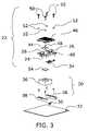
- FIG. 2is a perspective view of the testing socket and modular sensor/heater/controller unit of FIG. 1 in a latched position.
- FIG. 10is a side elevation view of a prior art integrated circuit testing socket.
- FIGS. 1 and 2show perspective views of a testing socket 20 and a modular sensor/heater/controller unit 22 according to an embodiment of the invention.
- the heatercan also be a cooler but hereinafter for simplification will only be referred to as a heater.
- Springs 24 on latch 26allow for easy and quick release of the heater unit 22 from the testing socket base 38 .
- FIG. 2shows the testing socket 20 and modular unit 22 in a closed position where board-side connector 30 located on the testing board 32 receives communication/power connector 34 located on the heater unit 22 .
- the heater 44connects flushly with a bottom surface of heat sink 46 and electrically communicates with the embedded microprocessor controller 42 for signal communication and electrically communicates with the communication/power connector 34 for power.
- the temperature sensor 48(see FIG. 4 ) is positioned within heater 44 and also communicates with the microprocessor controller 42 for signal communication and the communication/power connector 34 for power.
- the heat sink 46that has the heater 44 and sensor 48 connected to its bottom surface, attaches to the guide plate 40 with a combination of barrel screws 50 and springs 52 . The combination provides a controlled force of the heater 44 and sensor 48 against an IC package 54 in open-top socket 36 when the testing socket 20 and modular unit 22 are in a closed position.
Landscapes
- Engineering & Computer Science (AREA)
- Physics & Mathematics (AREA)
- General Physics & Mathematics (AREA)
- Computer Hardware Design (AREA)
- Microelectronics & Electronic Packaging (AREA)
- General Engineering & Computer Science (AREA)
- Environmental & Geological Engineering (AREA)
- Health & Medical Sciences (AREA)
- Toxicology (AREA)
- Testing Of Individual Semiconductor Devices (AREA)
Abstract
Description
Claims (20)
Priority Applications (6)
| Application Number | Priority Date | Filing Date | Title |
|---|---|---|---|
| US11/069,589US7042240B2 (en) | 2004-02-27 | 2005-02-28 | Burn-in testing apparatus and method |
| US11/368,283US7394271B2 (en) | 2004-02-27 | 2006-03-03 | Temperature sensing and prediction in IC sockets |
| US11/367,983US7187189B2 (en) | 2004-02-27 | 2006-03-03 | Burn-in testing apparatus and method |
| US11/562,294US7312620B2 (en) | 2004-02-27 | 2006-11-21 | Burn-in testing apparatus and method |
| US11/929,569US7482825B2 (en) | 2004-02-27 | 2007-10-30 | Burn-in testing apparatus and method |
| US12/136,600US20080238466A1 (en) | 2004-02-27 | 2008-06-10 | Temperature sensing and prediction in ic sockets |
Applications Claiming Priority (3)
| Application Number | Priority Date | Filing Date | Title |
|---|---|---|---|
| US54830304P | 2004-02-27 | 2004-02-27 | |
| US10/920,531US7123037B2 (en) | 2004-02-27 | 2004-08-17 | Integrated circuit temperature sensing device and method |
| US11/069,589US7042240B2 (en) | 2004-02-27 | 2005-02-28 | Burn-in testing apparatus and method |
Related Parent Applications (1)
| Application Number | Title | Priority Date | Filing Date |
|---|---|---|---|
| US10/920,531Continuation-In-PartUS7123037B2 (en) | 2004-02-27 | 2004-08-17 | Integrated circuit temperature sensing device and method |
Related Child Applications (2)
| Application Number | Title | Priority Date | Filing Date |
|---|---|---|---|
| US11/367,983ContinuationUS7187189B2 (en) | 2004-02-27 | 2006-03-03 | Burn-in testing apparatus and method |
| US11/368,283Continuation-In-PartUS7394271B2 (en) | 2004-02-27 | 2006-03-03 | Temperature sensing and prediction in IC sockets |
Publications (2)
| Publication Number | Publication Date |
|---|---|
| US20050206368A1 US20050206368A1 (en) | 2005-09-22 |
| US7042240B2true US7042240B2 (en) | 2006-05-09 |
Family
ID=36639663
Family Applications (4)
| Application Number | Title | Priority Date | Filing Date |
|---|---|---|---|
| US11/069,589Expired - LifetimeUS7042240B2 (en) | 2004-02-27 | 2005-02-28 | Burn-in testing apparatus and method |
| US11/367,983Expired - LifetimeUS7187189B2 (en) | 2004-02-27 | 2006-03-03 | Burn-in testing apparatus and method |
| US11/562,294Expired - LifetimeUS7312620B2 (en) | 2004-02-27 | 2006-11-21 | Burn-in testing apparatus and method |
| US11/929,569Expired - LifetimeUS7482825B2 (en) | 2004-02-27 | 2007-10-30 | Burn-in testing apparatus and method |
Family Applications After (3)
| Application Number | Title | Priority Date | Filing Date |
|---|---|---|---|
| US11/367,983Expired - LifetimeUS7187189B2 (en) | 2004-02-27 | 2006-03-03 | Burn-in testing apparatus and method |
| US11/562,294Expired - LifetimeUS7312620B2 (en) | 2004-02-27 | 2006-11-21 | Burn-in testing apparatus and method |
| US11/929,569Expired - LifetimeUS7482825B2 (en) | 2004-02-27 | 2007-10-30 | Burn-in testing apparatus and method |
Country Status (1)
| Country | Link |
|---|---|
| US (4) | US7042240B2 (en) |
Cited By (33)
| Publication number | Priority date | Publication date | Assignee | Title |
|---|---|---|---|---|
| US20050240844A1 (en)* | 2001-07-02 | 2005-10-27 | Intel Corporation | Integrated circuit burn-in methods and apparatus |
| US20060290366A1 (en)* | 2005-06-28 | 2006-12-28 | Intel Corporation | Monitoring multiple electronic devices under test |
| US20060290370A1 (en)* | 2004-02-27 | 2006-12-28 | Wells-Cti, Llc, An Oregon Limited Liability Company | Temperature control in ic sockets |
| US20070075721A1 (en)* | 2004-02-27 | 2007-04-05 | Wells-Cti, Llc | Burn-in testing apparatus and method |
| US20070144626A1 (en)* | 2005-12-26 | 2007-06-28 | Fujitsu Limited | In-furnace temperature measuring method |
| US20080116924A1 (en)* | 2006-11-20 | 2008-05-22 | Gerard Blaney | Device under test pogo pin type contact element |
| US20080116922A1 (en)* | 2006-11-20 | 2008-05-22 | Gerard Blaney | Testing system contactor |
| US20090002010A1 (en)* | 2007-06-26 | 2009-01-01 | Anthony Yeh Chiing Wong | Active thermal control using a burn-in socket heating element |
| US20100158068A1 (en)* | 2008-12-22 | 2010-06-24 | Embraer - Empresa Brasileira De Aeronautica S.A. | Bleed leakage detection system and method |
| US20100193175A1 (en)* | 2009-02-05 | 2010-08-05 | International Business Machines Corporation | Heat Sink Apparatus with Extendable Pin Fins |
| US8937482B1 (en) | 2011-06-28 | 2015-01-20 | Sensata Technologies, Inc. | Apparatus and method for ramping and controlling the temperature of a component using a vortex tube |
| US20170321966A1 (en)* | 2014-12-03 | 2017-11-09 | Ge Intelligent Platforms, Inc. | Combined energy dissipation apparatus and method |
| US9900975B2 (en)* | 2016-03-25 | 2018-02-20 | Adlink Technology Inc. | Chip heater and heating aid arrangement |
| US11372043B2 (en) | 2019-08-21 | 2022-06-28 | Micron Technology, Inc. | Heat spreaders for use in semiconductor device testing, such as burn-in testing |
| US11385281B2 (en)* | 2019-08-21 | 2022-07-12 | Micron Technology, Inc. | Heat spreaders for use in semiconductor device testing, such as burn-in testing |
| US11493551B2 (en)* | 2020-06-22 | 2022-11-08 | Advantest Test Solutions, Inc. | Integrated test cell using active thermal interposer (ATI) with parallel socket actuation |
| US11549981B2 (en) | 2020-10-01 | 2023-01-10 | Advantest Test Solutions, Inc. | Thermal solution for massively parallel testing |
| US11567119B2 (en) | 2020-12-04 | 2023-01-31 | Advantest Test Solutions, Inc. | Testing system including active thermal interposer device |
| US11573262B2 (en) | 2020-12-31 | 2023-02-07 | Advantest Test Solutions, Inc. | Multi-input multi-zone thermal control for device testing |
| US11587640B2 (en) | 2021-03-08 | 2023-02-21 | Advantest Test Solutions, Inc. | Carrier based high volume system level testing of devices with pop structures |
| US20230083634A1 (en)* | 2021-09-14 | 2023-03-16 | Advantest Test Solutions, Inc. | Parallel test cell with self actuated sockets |
| US11656272B1 (en) | 2022-10-21 | 2023-05-23 | AEM Holdings Ltd. | Test system with a thermal head comprising a plurality of adapters and one or more cold plates for independent control of zones |
| US11656273B1 (en) | 2021-11-05 | 2023-05-23 | Advantest Test Solutions, Inc. | High current device testing apparatus and systems |
| US11674999B2 (en) | 2020-11-19 | 2023-06-13 | Advantest Test Solutions, Inc. | Wafer scale active thermal interposer for device testing |
| US11693051B1 (en) | 2022-10-21 | 2023-07-04 | AEM Holdings Ltd. | Thermal head for independent control of zones |
| US11796589B1 (en) | 2022-10-21 | 2023-10-24 | AEM Holdings Ltd. | Thermal head for independent control of zones |
| US11808812B2 (en) | 2020-11-02 | 2023-11-07 | Advantest Test Solutions, Inc. | Passive carrier-based device delivery for slot-based high-volume semiconductor test system |
| US11821913B2 (en) | 2020-11-02 | 2023-11-21 | Advantest Test Solutions, Inc. | Shielded socket and carrier for high-volume test of semiconductor devices |
| US11828795B1 (en) | 2022-10-21 | 2023-11-28 | AEM Holdings Ltd. | Test system with a thermal head comprising a plurality of adapters for independent thermal control of zones |
| US11828796B1 (en) | 2023-05-02 | 2023-11-28 | AEM Holdings Ltd. | Integrated heater and temperature measurement |
| US11835549B2 (en) | 2022-01-26 | 2023-12-05 | Advantest Test Solutions, Inc. | Thermal array with gimbal features and enhanced thermal performance |
| US12259427B2 (en) | 2022-10-21 | 2025-03-25 | AEM Singapore Pte, LTD. | Thermal head comprising a plurality of adapters for independent thermal control of zones |
| US12411167B2 (en) | 2022-01-26 | 2025-09-09 | Advantest Test Solutions, Inc. | Tension-based socket gimbal for engaging device under test with thermal array |
Families Citing this family (41)
| Publication number | Priority date | Publication date | Assignee | Title |
|---|---|---|---|---|
| US7394271B2 (en)* | 2004-02-27 | 2008-07-01 | Wells-Cti, Llc | Temperature sensing and prediction in IC sockets |
| US7375542B2 (en)* | 2004-06-30 | 2008-05-20 | Teradyne, Inc. | Automated test equipment with DIB mounted three dimensional tester electronics bricks |
| US8029186B2 (en) | 2004-11-05 | 2011-10-04 | International Business Machines Corporation | Method for thermal characterization under non-uniform heat load |
| TWM288053U (en)* | 2005-08-30 | 2006-02-21 | Hon Hai Prec Ind Co Ltd | Electrical connector |
| JP5095964B2 (en)* | 2006-07-03 | 2012-12-12 | スリーエム イノベイティブ プロパティズ カンパニー | Attachment for socket and semiconductor device test apparatus having the same |
| WO2008035650A1 (en)* | 2006-09-19 | 2008-03-27 | Panasonic Corporation | Socket, module board, and inspection system using the module board |
| US8026515B1 (en)* | 2006-09-27 | 2011-09-27 | Nvidia Corporation | Platform-independent system and method for controlling a temperature of an integrated circuit |
| US20080302783A1 (en)* | 2007-06-08 | 2008-12-11 | Anthony Yeh Chiing Wong | Actively controlled embedded burn-in board thermal heaters |
| KR100901523B1 (en)* | 2007-07-16 | 2009-06-08 | (주)테크윙 | Opener and buffer table for test handler |
| US7960992B2 (en)* | 2009-02-25 | 2011-06-14 | Kingston Technology Corp. | Conveyor-based memory-module tester with elevators distributing moving test motherboards among parallel conveyors for testing |
| CN101692428B (en)* | 2009-09-09 | 2011-03-23 | 贵州振华风光半导体有限公司 | Integrating method of hybrid integrated circuit with controllable working temperature |
| US9804223B2 (en)* | 2009-11-30 | 2017-10-31 | Essai, Inc. | Systems and methods for conforming test tooling to integrated circuit device with heater socket |
| US7914313B1 (en) | 2010-02-04 | 2011-03-29 | Plastronics Socket Partners, Ltd. | Clamping mechanism for an IC socket |
| US8756549B2 (en)* | 2011-01-05 | 2014-06-17 | International Business Machines Corporation | Integrated circuit chip incorporating embedded thermal radiators for localized, on-demand, heating and a system and method for designing such an integrated circuit chip |
| US8547122B2 (en)* | 2011-07-11 | 2013-10-01 | Microchip Technology Incorporated | Temperature measurement of active device under test on strip tester |
| US9069039B1 (en)* | 2011-09-30 | 2015-06-30 | Emc Corporation | Power measurement transducer |
| CN102891113B (en)* | 2012-10-18 | 2015-03-04 | 贵州振华风光半导体有限公司 | Integrating method for high-sensitivity temperature-controlled thick film hybrid integrated circuit |
| US9476936B1 (en)* | 2013-03-15 | 2016-10-25 | Johnstech International Corporation | Thermal management for microcircuit testing system |
| CN103487689B (en)* | 2013-09-24 | 2016-08-24 | 国家电网公司 | A kind of plug-in unit degradation detecting device |
| WO2016160730A1 (en)* | 2015-03-28 | 2016-10-06 | Essai, Inc. | Systems and methods for conforming test tooling to integrated circuit device with heater socket |
| US10209297B2 (en)* | 2016-01-11 | 2019-02-19 | Texas Instruments Incorporated | Low cost apparatus for insitu testing of packaged integrated circuits during stressing |
| KR101792208B1 (en)* | 2016-02-26 | 2017-10-31 | 주식회사 아이에스시 | Socket for testing semiconductor device |
| EP3465238A4 (en)* | 2016-06-02 | 2020-01-22 | KES Systems, Inc. | SYSTEM AND METHOD FOR A SEMICONDUCTOR'S BURN-IN TEST |
| US10126352B1 (en)* | 2016-07-06 | 2018-11-13 | Ambarella, Inc. | Method for enhancing stability, robustness and throughput of semiconductor device test machines in low temperature conditions |
| EP3568706B1 (en)* | 2017-01-13 | 2023-05-10 | ams Sensors Singapore Pte. Ltd. | Apparatus for testing an optoelectronic device and method of operating the same |
| TWI735686B (en)* | 2017-10-20 | 2021-08-11 | 鴻騰精密科技股份有限公司 | Electrical connector assembly |
| IT201700121768A1 (en)* | 2017-10-26 | 2019-04-26 | Microtest S R L | An improvement of a heating device to perform temperature tests on electronic components stored within a socket |
| TWI686691B (en)* | 2018-08-16 | 2020-03-01 | 緯穎科技服務股份有限公司 | Electronic apparatus and passive component |
| US11047905B2 (en)* | 2019-05-31 | 2021-06-29 | Analog Devices International Unlimited Company | Contactor with integrated memory |
| CN112946007A (en)* | 2019-11-26 | 2021-06-11 | 杭州可靠性仪器厂 | Oven and aging test device thereof |
| US20220223441A1 (en)* | 2021-01-08 | 2022-07-14 | Kla Corporation | Process condition sensing apparatus |
| TWI782443B (en)* | 2021-03-10 | 2022-11-01 | 陽榮科技股份有限公司 | Temperature control device for semiconductor testing |
| FR3125885B1 (en) | 2021-07-29 | 2023-07-28 | St Microelectronics Grenoble 2 | Device and method for testing electronic chips |
| TWI803004B (en)* | 2021-09-24 | 2023-05-21 | 伊士博國際商業股份有限公司 | Supplied with convection test socket |
| US11977006B2 (en)* | 2021-11-01 | 2024-05-07 | Juniper Networks, Inc. | Test system for evaluating thermal performance of a heatsink |
| CN114236417B (en)* | 2021-12-02 | 2025-05-02 | 中国空间技术研究院 | A device for monitoring the junction temperature during aging of power supply devices |
| US11650246B1 (en) | 2022-02-02 | 2023-05-16 | Western Digital Technologies, Inc. | Localized onboard socket heating elements for burn-in test boards |
| CN115808613B (en)* | 2023-01-17 | 2023-05-09 | 天芯电子科技(南京)有限公司 | Chip heat dissipation test seat with heat measurement function |
| WO2024210237A1 (en)* | 2023-04-07 | 2024-10-10 | 주식회사 아이에스시 | Test socket |
| KR102846967B1 (en)* | 2023-05-23 | 2025-08-18 | 주식회사 티에프이 | Semiconductor package heat generation simulation unit for checking heat distrubution of burn-in board and method for acquiring heat distrubution of burn-in board |
| US12237184B1 (en)* | 2023-11-13 | 2025-02-25 | Semight Instruments Co., Ltd | Heating structure and wafer test device |
Citations (7)
| Publication number | Priority date | Publication date | Assignee | Title |
|---|---|---|---|---|
| US5164661A (en)* | 1991-05-31 | 1992-11-17 | Ej Systems, Inc. | Thermal control system for a semi-conductor burn-in |
| US5414370A (en)* | 1991-07-19 | 1995-05-09 | Sumitomo Electric Industries, Ltd. | Burn-in apparatus and method which individually controls the temperature of a plurality of semiconductor devices |
| US6191599B1 (en)* | 1998-10-09 | 2001-02-20 | International Business Machines Corporation | IC device under test temperature control fixture |
| US6230497B1 (en)* | 1999-12-06 | 2001-05-15 | Motorola, Inc. | Semiconductor circuit temperature monitoring and controlling apparatus and method |
| US6362640B1 (en)* | 2000-06-26 | 2002-03-26 | Advanced Micro Devices, Inc. | Design of IC package test handler with temperature controller for minimized maintenance |
| US6477047B1 (en)* | 2000-11-30 | 2002-11-05 | Advanced Micro Devices, Inc. | Temperature sensor mounting for accurate measurement and durability |
| US6636062B2 (en)* | 2001-04-10 | 2003-10-21 | Delta Design, Inc. | Temperature control device for an electronic component |
Family Cites Families (9)
| Publication number | Priority date | Publication date | Assignee | Title |
|---|---|---|---|---|
| US4962356A (en)* | 1988-08-19 | 1990-10-09 | Cray Research, Inc. | Integrated circuit test socket |
| US4940935A (en)* | 1989-08-28 | 1990-07-10 | Ried Ashman Manufacturing | Automatic SMD tester |
| US5420521A (en)* | 1992-10-27 | 1995-05-30 | Ej Systems, Inc. | Burn-in module |
| US5302934A (en) | 1993-04-02 | 1994-04-12 | Therm-O-Disc, Incorporated | Temperature sensor |
| US5911897A (en) | 1997-01-13 | 1999-06-15 | Micro Control Company | Temperature control for high power burn-in for integrated circuits |
| US6668570B2 (en) | 2001-05-31 | 2003-12-30 | Kryotech, Inc. | Apparatus and method for controlling the temperature of an electronic device under test |
| US7123037B2 (en) | 2004-02-27 | 2006-10-17 | Wells-Cti, Llc | Integrated circuit temperature sensing device and method |
| US7042240B2 (en)* | 2004-02-27 | 2006-05-09 | Wells-Cti, Llc | Burn-in testing apparatus and method |
| US6981882B1 (en)* | 2005-03-29 | 2006-01-03 | Ironwood Electronics, Inc. | Packaged device adapter with torque limiting assembly |
- 2005
- 2005-02-28USUS11/069,589patent/US7042240B2/ennot_activeExpired - Lifetime
- 2006
- 2006-03-03USUS11/367,983patent/US7187189B2/ennot_activeExpired - Lifetime
- 2006-11-21USUS11/562,294patent/US7312620B2/ennot_activeExpired - Lifetime
- 2007
- 2007-10-30USUS11/929,569patent/US7482825B2/ennot_activeExpired - Lifetime
Patent Citations (7)
| Publication number | Priority date | Publication date | Assignee | Title |
|---|---|---|---|---|
| US5164661A (en)* | 1991-05-31 | 1992-11-17 | Ej Systems, Inc. | Thermal control system for a semi-conductor burn-in |
| US5414370A (en)* | 1991-07-19 | 1995-05-09 | Sumitomo Electric Industries, Ltd. | Burn-in apparatus and method which individually controls the temperature of a plurality of semiconductor devices |
| US6191599B1 (en)* | 1998-10-09 | 2001-02-20 | International Business Machines Corporation | IC device under test temperature control fixture |
| US6230497B1 (en)* | 1999-12-06 | 2001-05-15 | Motorola, Inc. | Semiconductor circuit temperature monitoring and controlling apparatus and method |
| US6362640B1 (en)* | 2000-06-26 | 2002-03-26 | Advanced Micro Devices, Inc. | Design of IC package test handler with temperature controller for minimized maintenance |
| US6477047B1 (en)* | 2000-11-30 | 2002-11-05 | Advanced Micro Devices, Inc. | Temperature sensor mounting for accurate measurement and durability |
| US6636062B2 (en)* | 2001-04-10 | 2003-10-21 | Delta Design, Inc. | Temperature control device for an electronic component |
Cited By (63)
| Publication number | Priority date | Publication date | Assignee | Title |
|---|---|---|---|---|
| US20050240844A1 (en)* | 2001-07-02 | 2005-10-27 | Intel Corporation | Integrated circuit burn-in methods and apparatus |
| US7449904B2 (en)* | 2001-07-02 | 2008-11-11 | Intel Corporation | Integrated circuit burn-in methods and apparatus |
| US7482825B2 (en) | 2004-02-27 | 2009-01-27 | Wells-Cti, Llc | Burn-in testing apparatus and method |
| US20060290370A1 (en)* | 2004-02-27 | 2006-12-28 | Wells-Cti, Llc, An Oregon Limited Liability Company | Temperature control in ic sockets |
| US20070075721A1 (en)* | 2004-02-27 | 2007-04-05 | Wells-Cti, Llc | Burn-in testing apparatus and method |
| US7312620B2 (en) | 2004-02-27 | 2007-12-25 | Wells-Cti, Llc | Burn-in testing apparatus and method |
| US20080054926A1 (en)* | 2004-02-27 | 2008-03-06 | Wells-Cti, Llc | Burn-in testing apparatus and method |
| US20060290366A1 (en)* | 2005-06-28 | 2006-12-28 | Intel Corporation | Monitoring multiple electronic devices under test |
| US20070144626A1 (en)* | 2005-12-26 | 2007-06-28 | Fujitsu Limited | In-furnace temperature measuring method |
| US7549794B2 (en)* | 2005-12-26 | 2009-06-23 | Fujitsu Limited | In-furnace temperature measuring method |
| US7728613B2 (en) | 2006-11-20 | 2010-06-01 | Analog Devices, Inc. | Device under test pogo pin type contact element |
| US20080116922A1 (en)* | 2006-11-20 | 2008-05-22 | Gerard Blaney | Testing system contactor |
| US7683649B2 (en) | 2006-11-20 | 2010-03-23 | Analog Devices, Inc. | Testing system contactor |
| US20080116924A1 (en)* | 2006-11-20 | 2008-05-22 | Gerard Blaney | Device under test pogo pin type contact element |
| US20090002010A1 (en)* | 2007-06-26 | 2009-01-01 | Anthony Yeh Chiing Wong | Active thermal control using a burn-in socket heating element |
| US7701238B2 (en)* | 2007-06-26 | 2010-04-20 | Intel Corporation | Active thermal control using a burn-in socket heating element |
| US20100158068A1 (en)* | 2008-12-22 | 2010-06-24 | Embraer - Empresa Brasileira De Aeronautica S.A. | Bleed leakage detection system and method |
| US8696196B2 (en)* | 2008-12-22 | 2014-04-15 | Embraer S.A. | Bleed leakage detection system and method |
| US20100193175A1 (en)* | 2009-02-05 | 2010-08-05 | International Business Machines Corporation | Heat Sink Apparatus with Extendable Pin Fins |
| US8910706B2 (en)* | 2009-02-05 | 2014-12-16 | International Business Machines Corporation | Heat sink apparatus with extendable pin fins |
| US8937482B1 (en) | 2011-06-28 | 2015-01-20 | Sensata Technologies, Inc. | Apparatus and method for ramping and controlling the temperature of a component using a vortex tube |
| US20170321966A1 (en)* | 2014-12-03 | 2017-11-09 | Ge Intelligent Platforms, Inc. | Combined energy dissipation apparatus and method |
| US9900975B2 (en)* | 2016-03-25 | 2018-02-20 | Adlink Technology Inc. | Chip heater and heating aid arrangement |
| US11385281B2 (en)* | 2019-08-21 | 2022-07-12 | Micron Technology, Inc. | Heat spreaders for use in semiconductor device testing, such as burn-in testing |
| US11372043B2 (en) | 2019-08-21 | 2022-06-28 | Micron Technology, Inc. | Heat spreaders for use in semiconductor device testing, such as burn-in testing |
| US12078672B2 (en) | 2019-08-21 | 2024-09-03 | Micron Technology, Inc. | Heat spreaders for use in semiconductor device testing, such as burn-in testing |
| TWI795785B (en)* | 2020-06-22 | 2023-03-11 | 美商前進測試解決股份有限公司 | Testing apparatus and method of configuring integrated test cell |
| US11493551B2 (en)* | 2020-06-22 | 2022-11-08 | Advantest Test Solutions, Inc. | Integrated test cell using active thermal interposer (ATI) with parallel socket actuation |
| US11841392B2 (en) | 2020-06-22 | 2023-12-12 | Advantest Test Solutiions, Inc. | Integrated test cell using active thermal interposer (ATI) with parallel socket actuation |
| US12345756B2 (en) | 2020-06-22 | 2025-07-01 | Advantest Test Solutions, Inc. | Integrated test cell using active thermal interposer (ATI) with parallel socket actuation |
| US11549981B2 (en) | 2020-10-01 | 2023-01-10 | Advantest Test Solutions, Inc. | Thermal solution for massively parallel testing |
| US11940487B2 (en) | 2020-10-01 | 2024-03-26 | Advantest Test Solutions, Inc. | Thermal solution for massively parallel testing |
| US11821913B2 (en) | 2020-11-02 | 2023-11-21 | Advantest Test Solutions, Inc. | Shielded socket and carrier for high-volume test of semiconductor devices |
| US11808812B2 (en) | 2020-11-02 | 2023-11-07 | Advantest Test Solutions, Inc. | Passive carrier-based device delivery for slot-based high-volume semiconductor test system |
| US12320852B2 (en) | 2020-11-02 | 2025-06-03 | Advantest Test Solutions, Inc. | Passive carrier-based device delivery for slot-based high-volume semiconductor test system |
| US12203958B2 (en) | 2020-11-02 | 2025-01-21 | Advantest Test Solutions, Inc. | Shielded socket and carrier for high-volume test of semiconductor devices |
| US11674999B2 (en) | 2020-11-19 | 2023-06-13 | Advantest Test Solutions, Inc. | Wafer scale active thermal interposer for device testing |
| US12320841B2 (en) | 2020-11-19 | 2025-06-03 | Advantest Test Solutions, Inc. | Wafer scale active thermal interposer for device testing |
| US11754620B2 (en) | 2020-12-04 | 2023-09-12 | Advantest Test Solutions, Inc. | DUT placement and handling for active thermal interposer device |
| US11774492B2 (en) | 2020-12-04 | 2023-10-03 | Advantest Test Solutions, Inc. | Test system including active thermal interposer device |
| US12216154B2 (en) | 2020-12-04 | 2025-02-04 | Advantest Test Solutions, Inc. | Active thermal interposer device |
| US11609266B2 (en) | 2020-12-04 | 2023-03-21 | Advantest Test Solutions, Inc. | Active thermal interposer device |
| US11846669B2 (en) | 2020-12-04 | 2023-12-19 | Advantest Test Solutions, Inc. | Active thermal interposer device |
| US11567119B2 (en) | 2020-12-04 | 2023-01-31 | Advantest Test Solutions, Inc. | Testing system including active thermal interposer device |
| US12203979B2 (en) | 2020-12-31 | 2025-01-21 | Advantest Test Solutions, Inc. | Multi-input multi-zone thermal control for device testing |
| US11573262B2 (en) | 2020-12-31 | 2023-02-07 | Advantest Test Solutions, Inc. | Multi-input multi-zone thermal control for device testing |
| US11852678B2 (en) | 2020-12-31 | 2023-12-26 | Advantest Test Solutions, Inc. | Multi-input multi-zone thermal control for device testing |
| US11587640B2 (en) | 2021-03-08 | 2023-02-21 | Advantest Test Solutions, Inc. | Carrier based high volume system level testing of devices with pop structures |
| US12374420B2 (en) | 2021-03-08 | 2025-07-29 | Advantest Test Solutions, Inc. | Carrier based high volume system level testing of devices with pop structures |
| US11742055B2 (en) | 2021-03-08 | 2023-08-29 | Advantest Test Solutions, Inc. | Carrier based high volume system level testing of devices with pop structures |
| US12235314B2 (en)* | 2021-09-14 | 2025-02-25 | Advantest Test Solutions, Inc | Parallel test cell with self actuated sockets |
| US20230083634A1 (en)* | 2021-09-14 | 2023-03-16 | Advantest Test Solutions, Inc. | Parallel test cell with self actuated sockets |
| US11656273B1 (en) | 2021-11-05 | 2023-05-23 | Advantest Test Solutions, Inc. | High current device testing apparatus and systems |
| US12411167B2 (en) | 2022-01-26 | 2025-09-09 | Advantest Test Solutions, Inc. | Tension-based socket gimbal for engaging device under test with thermal array |
| US11835549B2 (en) | 2022-01-26 | 2023-12-05 | Advantest Test Solutions, Inc. | Thermal array with gimbal features and enhanced thermal performance |
| US12210056B2 (en) | 2022-01-26 | 2025-01-28 | Advantest Test Solutions, Inc. | Thermal array with gimbal features and enhanced thermal performance |
| US11828795B1 (en) | 2022-10-21 | 2023-11-28 | AEM Holdings Ltd. | Test system with a thermal head comprising a plurality of adapters for independent thermal control of zones |
| US12259427B2 (en) | 2022-10-21 | 2025-03-25 | AEM Singapore Pte, LTD. | Thermal head comprising a plurality of adapters for independent thermal control of zones |
| US11693051B1 (en) | 2022-10-21 | 2023-07-04 | AEM Holdings Ltd. | Thermal head for independent control of zones |
| US11656272B1 (en) | 2022-10-21 | 2023-05-23 | AEM Holdings Ltd. | Test system with a thermal head comprising a plurality of adapters and one or more cold plates for independent control of zones |
| US11796589B1 (en) | 2022-10-21 | 2023-10-24 | AEM Holdings Ltd. | Thermal head for independent control of zones |
| US12061227B1 (en) | 2023-05-02 | 2024-08-13 | Aem Singapore Pte. Ltd. | Integrated heater and temperature measurement |
| US11828796B1 (en) | 2023-05-02 | 2023-11-28 | AEM Holdings Ltd. | Integrated heater and temperature measurement |
Also Published As
| Publication number | Publication date |
|---|---|
| US20050206368A1 (en) | 2005-09-22 |
| US7312620B2 (en) | 2007-12-25 |
| US20060145718A1 (en) | 2006-07-06 |
| US7187189B2 (en) | 2007-03-06 |
| US7482825B2 (en) | 2009-01-27 |
| US20080054926A1 (en) | 2008-03-06 |
| US20070075721A1 (en) | 2007-04-05 |
Similar Documents
| Publication | Publication Date | Title |
|---|---|---|
| US7042240B2 (en) | Burn-in testing apparatus and method | |
| WO2005084328A2 (en) | Burn-in testing apparatus and method | |
| US7394271B2 (en) | Temperature sensing and prediction in IC sockets | |
| US6504392B2 (en) | Actively controlled heat sink for convective burn-in oven | |
| CN102317802B (en) | Integrated unit for electrical/reliability testing with improved thermal control | |
| CN1922501A (en) | Aging testing apparatus and method | |
| KR101990666B1 (en) | Test system with localized heating and method of manufacture thereof | |
| JP2020511788A (en) | Electronic tester | |
| WO2006096543A2 (en) | Temperature sensing and prediction in ic sockets | |
| EP3992645B1 (en) | Placement table, testing device, and testing method | |
| EP2259297A1 (en) | Probe wafer, probe device, and testing system | |
| CN118215847A (en) | Local on-board socket heating elements for burn-in test boards | |
| US20070132471A1 (en) | Method and apparatus for testing integrated circuits over a range of temperatures | |
| HK1101250A (en) | Burn-in testing apparatus and method | |
| KR200179993Y1 (en) | Apparatus for testing semiconductor package | |
| US20030234644A1 (en) | Force measurement on test and system level test environment under a printed circuit board |
Legal Events
| Date | Code | Title | Description |
|---|---|---|---|
| AS | Assignment | Owner name:WELLS-CTI, LLC, AN OREGON LIMITED LIABILITY COMPAN Free format text:ASSIGNMENT OF ASSIGNORS INTEREST;ASSIGNORS:LOPEZ, CHRISTOPHER A.;DENHEYER, BRIAN J.;KUENSTER, GORDON B.;REEL/FRAME:016057/0560;SIGNING DATES FROM 20050308 TO 20050407 | |
| FEPP | Fee payment procedure | Free format text:PAYOR NUMBER ASSIGNED (ORIGINAL EVENT CODE: ASPN); ENTITY STATUS OF PATENT OWNER: LARGE ENTITY | |
| STCF | Information on status: patent grant | Free format text:PATENTED CASE | |
| CC | Certificate of correction | ||
| AS | Assignment | Owner name:SILICON VALLEY BANK, CALIFORNIA Free format text:SECURITY AGREEMENT;ASSIGNOR:WELLS-CTI, LLC;REEL/FRAME:018420/0121 Effective date:20060901 | |
| FPAY | Fee payment | Year of fee payment:4 | |
| AS | Assignment | Owner name:SENSATA TECHNOLOGIES, INC., MASSACHUSETTS Free format text:ASSIGNMENT OF ASSIGNORS INTEREST;ASSIGNOR:WELLS-CTI, LLC;REEL/FRAME:029139/0219 Effective date:20121001 | |
| FEPP | Fee payment procedure | Free format text:PAT HOLDER NO LONGER CLAIMS SMALL ENTITY STATUS, ENTITY STATUS SET TO UNDISCOUNTED (ORIGINAL EVENT CODE: STOL); ENTITY STATUS OF PATENT OWNER: LARGE ENTITY | |
| REFU | Refund | Free format text:REFUND - PAYMENT OF MAINTENANCE FEE, 8TH YR, SMALL ENTITY (ORIGINAL EVENT CODE: R2552); ENTITY STATUS OF PATENT OWNER: LARGE ENTITY | |
| CC | Certificate of correction | ||
| AS | Assignment | Owner name:WELLS-CTI LLC, WASHINGTON Free format text:RELEASE BY SECURED PARTY;ASSIGNOR:SILICON VALLEY BANK;REEL/FRAME:029430/0786 Effective date:20121127 | |
| AS | Assignment | Owner name:WELLS-CTI, LLC, WASHINGTON Free format text:RELEASE OF INTELLECTUAL PROPERTY SECURITY AGREEMENT BY SECURED PARTY AS PREVIOUSLY RECORDED ON REEL/FRAME 018420/0121;ASSIGNOR:SILICON VALLEY BANK;REEL/FRAME:029854/0805 Effective date:20121217 | |
| FPAY | Fee payment | Year of fee payment:8 | |
| MAFP | Maintenance fee payment | Free format text:PAYMENT OF MAINTENANCE FEE, 12TH YEAR, LARGE ENTITY (ORIGINAL EVENT CODE: M1553) Year of fee payment:12 | |
| AS | Assignment | Owner name:LTI HOLDINGS, INC., CALIFORNIA Free format text:ASSIGNMENT OF ASSIGNORS INTEREST;ASSIGNOR:SENSATA TECHNOLOGIES, INC.;REEL/FRAME:061350/0370 Effective date:20220701 |