US7042180B2 - Brushless and sensorless DC motor control system with locked and stopped rotor detection - Google Patents
Brushless and sensorless DC motor control system with locked and stopped rotor detectionDownload PDFInfo
- Publication number
- US7042180B2 US7042180B2US10/763,452US76345204AUS7042180B2US 7042180 B2US7042180 B2US 7042180B2US 76345204 AUS76345204 AUS 76345204AUS 7042180 B2US7042180 B2US 7042180B2
- Authority
- US
- United States
- Prior art keywords
- motor
- driver outputs
- phase coils
- coupled
- fault
- Prior art date
- Legal status (The legal status is an assumption and is not a legal conclusion. Google has not performed a legal analysis and makes no representation as to the accuracy of the status listed.)
- Expired - Lifetime
Links
- 238000001514detection methodMethods0.000titleclaimsabstractdescription65
- 238000000034methodMethods0.000claimsdescription23
- 239000003990capacitorSubstances0.000claimsdescription21
- 230000001419dependent effectEffects0.000claimsdescription5
- 239000012530fluidSubstances0.000claimsdescription5
- 230000008878couplingEffects0.000claimsdescription3
- 238000010168coupling processMethods0.000claimsdescription3
- 238000005859coupling reactionMethods0.000claimsdescription3
- 238000005461lubricationMethods0.000claims2
- 230000003287optical effectEffects0.000claims1
- 238000005070samplingMethods0.000abstractdescription9
- 238000010586diagramMethods0.000description11
- 230000001276controlling effectEffects0.000description9
- 230000001934delayEffects0.000description6
- 238000012544monitoring processMethods0.000description6
- 230000008901benefitEffects0.000description5
- 230000000737periodic effectEffects0.000description5
- 239000003507refrigerantSubstances0.000description3
- 238000001816coolingMethods0.000description2
- 238000005516engineering processMethods0.000description2
- 230000001681protective effectEffects0.000description2
- 239000004065semiconductorSubstances0.000description2
- 101000940063Homo sapiens Ubiquitin-conjugating enzyme E2 variant 2Proteins0.000description1
- 102100031122Ubiquitin-conjugating enzyme E2 variant 2Human genes0.000description1
- 239000002253acidSubstances0.000description1
- 230000004913activationEffects0.000description1
- 230000006978adaptationEffects0.000description1
- 230000000903blocking effectEffects0.000description1
- 238000009529body temperature measurementMethods0.000description1
- 238000006243chemical reactionMethods0.000description1
- 230000001143conditioned effectEffects0.000description1
- 230000003750conditioning effectEffects0.000description1
- 238000002405diagnostic procedureMethods0.000description1
- 230000000694effectsEffects0.000description1
- 230000007613environmental effectEffects0.000description1
- 239000007788liquidSubstances0.000description1
- 239000000314lubricantSubstances0.000description1
- 238000012986modificationMethods0.000description1
- 230000004048modificationEffects0.000description1
- 230000008569processEffects0.000description1
- 238000012545processingMethods0.000description1
- 238000005057refrigerationMethods0.000description1
- 230000001105regulatory effectEffects0.000description1
- 238000007789sealingMethods0.000description1
- 238000004804windingMethods0.000description1
Images


Classifications
- F—MECHANICAL ENGINEERING; LIGHTING; HEATING; WEAPONS; BLASTING
- F04—POSITIVE - DISPLACEMENT MACHINES FOR LIQUIDS; PUMPS FOR LIQUIDS OR ELASTIC FLUIDS
- F04B—POSITIVE-DISPLACEMENT MACHINES FOR LIQUIDS; PUMPS
- F04B35/00—Piston pumps specially adapted for elastic fluids and characterised by the driving means to their working members, or by combination with, or adaptation to, specific driving engines or motors, not otherwise provided for
- F04B35/04—Piston pumps specially adapted for elastic fluids and characterised by the driving means to their working members, or by combination with, or adaptation to, specific driving engines or motors, not otherwise provided for the means being electric
- F—MECHANICAL ENGINEERING; LIGHTING; HEATING; WEAPONS; BLASTING
- F04—POSITIVE - DISPLACEMENT MACHINES FOR LIQUIDS; PUMPS FOR LIQUIDS OR ELASTIC FLUIDS
- F04B—POSITIVE-DISPLACEMENT MACHINES FOR LIQUIDS; PUMPS
- F04B49/00—Control, e.g. of pump delivery, or pump pressure of, or safety measures for, machines, pumps, or pumping installations, not otherwise provided for, or of interest apart from, groups F04B1/00 - F04B47/00
- F04B49/02—Stopping, starting, unloading or idling control
- F—MECHANICAL ENGINEERING; LIGHTING; HEATING; WEAPONS; BLASTING
- F04—POSITIVE - DISPLACEMENT MACHINES FOR LIQUIDS; PUMPS FOR LIQUIDS OR ELASTIC FLUIDS
- F04B—POSITIVE-DISPLACEMENT MACHINES FOR LIQUIDS; PUMPS
- F04B49/00—Control, e.g. of pump delivery, or pump pressure of, or safety measures for, machines, pumps, or pumping installations, not otherwise provided for, or of interest apart from, groups F04B1/00 - F04B47/00
- F04B49/06—Control using electricity
- F04B49/065—Control using electricity and making use of computers
- H—ELECTRICITY
- H02—GENERATION; CONVERSION OR DISTRIBUTION OF ELECTRIC POWER
- H02P—CONTROL OR REGULATION OF ELECTRIC MOTORS, ELECTRIC GENERATORS OR DYNAMO-ELECTRIC CONVERTERS; CONTROLLING TRANSFORMERS, REACTORS OR CHOKE COILS
- H02P29/00—Arrangements for regulating or controlling electric motors, appropriate for both AC and DC motors
- H02P29/02—Providing protection against overload without automatic interruption of supply
- H—ELECTRICITY
- H02—GENERATION; CONVERSION OR DISTRIBUTION OF ELECTRIC POWER
- H02P—CONTROL OR REGULATION OF ELECTRIC MOTORS, ELECTRIC GENERATORS OR DYNAMO-ELECTRIC CONVERTERS; CONTROLLING TRANSFORMERS, REACTORS OR CHOKE COILS
- H02P6/00—Arrangements for controlling synchronous motors or other dynamo-electric motors using electronic commutation dependent on the rotor position; Electronic commutators therefor
- H02P6/12—Monitoring commutation; Providing indication of commutation failure
- H—ELECTRICITY
- H02—GENERATION; CONVERSION OR DISTRIBUTION OF ELECTRIC POWER
- H02P—CONTROL OR REGULATION OF ELECTRIC MOTORS, ELECTRIC GENERATORS OR DYNAMO-ELECTRIC CONVERTERS; CONTROLLING TRANSFORMERS, REACTORS OR CHOKE COILS
- H02P6/00—Arrangements for controlling synchronous motors or other dynamo-electric motors using electronic commutation dependent on the rotor position; Electronic commutators therefor
- H02P6/14—Electronic commutators
- H02P6/16—Circuit arrangements for detecting position
- H02P6/18—Circuit arrangements for detecting position without separate position detecting elements
- H02P6/182—Circuit arrangements for detecting position without separate position detecting elements using back-emf in windings
- H—ELECTRICITY
- H02—GENERATION; CONVERSION OR DISTRIBUTION OF ELECTRIC POWER
- H02P—CONTROL OR REGULATION OF ELECTRIC MOTORS, ELECTRIC GENERATORS OR DYNAMO-ELECTRIC CONVERTERS; CONTROLLING TRANSFORMERS, REACTORS OR CHOKE COILS
- H02P6/00—Arrangements for controlling synchronous motors or other dynamo-electric motors using electronic commutation dependent on the rotor position; Electronic commutators therefor
- H02P6/34—Modelling or simulation for control purposes
- Y—GENERAL TAGGING OF NEW TECHNOLOGICAL DEVELOPMENTS; GENERAL TAGGING OF CROSS-SECTIONAL TECHNOLOGIES SPANNING OVER SEVERAL SECTIONS OF THE IPC; TECHNICAL SUBJECTS COVERED BY FORMER USPC CROSS-REFERENCE ART COLLECTIONS [XRACs] AND DIGESTS
- Y10—TECHNICAL SUBJECTS COVERED BY FORMER USPC
- Y10S—TECHNICAL SUBJECTS COVERED BY FORMER USPC CROSS-REFERENCE ART COLLECTIONS [XRACs] AND DIGESTS
- Y10S388/00—Electricity: motor control systems
- Y10S388/907—Specific control circuit element or device
- Y10S388/909—Monitoring means
Definitions
- the present inventionrelates to DC motor controllers, and, in particular, a motor control system that includes locked and lost rotor detection for a brushless and sensorless DC motor.
- DC motorsFor certain electric motor applications, such as driving a compressor or a pump, using DC motors is generally more advantageous then using AC motors.
- compressor start-uprequires a high torque at low speed start-up, which typically cannot be managed well by AC motors, especially AC motors having open loop controllers. Additionally, at lower compressor loads, the compressor may be more efficiently run at lower speeds.
- DC motorshandle variable speed and high torque, low speed applications more effectively than do AC motors and control systems.
- a variable speed DC motoris generally used, particularly a brushless DC (BLDC) motor.
- BLDCbrushless DC
- one difficulty with using a BLDC motoris detecting a locked motor rotor, such as from motor bearing failure or debris blocking movement or damaging the phase coils.
- Another difficultyis detecting a rotor stopped from the loss of rotor phase lock, which the motor controller requires for proper electronic commutation of the phase coils in a BLDC motor.
- a hermetically sealed compressorgenerally includes lubricant and refrigerant which, when heated by compressor operation and exposed to moisture, can form an acid that is corrosive to sensors.
- additional electrical connectionsmust be carried through the wall of the hermetically sealed chamber without compromising the hermetic sealing, adding further expense and an additional possible point of failure of the hermetic seal.
- One common solution to detecting a locked or stopped rotor in electric motor applicationsis sensing a motor current drawn by the motor coils that is higher than the normal current of a running motor.
- a locked rotor condition in a typical nonvariable electric motormay cause the motor current to exceed 80 amps, while normal high-speed motor operation only requires 10 to 15 amps.
- a locked or stopped rotor conditionmay draw less current than normal running current, for example, 30 amps for a stopped rotor, while normal high RPM operation may draw 40 amps.
- conventional over-current sensing detectiondoes not provide a solution for detecting a locked or stopped rotor.
- the present inventionprovides a method and a motor control system for detecting a locked or stopped rotor for a brushless and sensorless DC motor system, including for example a compressor, pump, or other application, for example, detecting a locked or stopped actuator for a valve or solenoid drive.
- the motor control systemincludes a protection and fault detection circuit capable of sampling back electromotive force (EMF) and a motor control circuit having an off-the-shelf motor control integrated circuit (IC).
- EMFback electromotive force
- ICoff-the-shelf motor control integrated circuit
- the protection and fault detection circuitmomentarily disables the motor control IC phase driver outputs by providing an over-current indication to the motor control IC. While the phase driver outputs are disabled, back EMF is generated by the motor if the motor rotor is still rotating. Thus, after disabling the phase driver outputs, the fault detection circuit measures back EMF to determine if the motor rotor is rotating or stopped.
- BLDCbrushless DC
- the inventive conceptcould also be applied to other types of motors and applications, for example, unsealed pumps, valves, or solenoid drives.
- BLDC motor applicationswithout a rotor position or other sensor, it is difficult to determine that the motor rotor has locked or that electronic commutation phase lock with the rotor has been lost by the motor control circuit, resulting in a stopped rotor.
- Back EMF detectionis accomplished by momentarily disabling the phase coil driver outputs of the motor control IC.
- the driver outputsmay be disabled by providing a signal to an available control input of the motor control IC For example, providing a signal to a current overload control input, thereby simulating an over-current condition and momentarily shutting down the motor control IC phase driver outputs.
- a back EMF sampling circuitmeasures the back EMF to determine whether the rotor is still in rotation. Back EMF is generated in the undriven phase coils by the movement of the motor's magnets past the phase coils.
- the duration of momentarily disabling the driver outputsis of sufficient duration to allow at least one magnet to pass by a phase coil at the lowest motor speed, yet of insufficient duration to substantially effect motor speed and torque, for example about 1.0 msec. If a threshold level of back EMF is detected, the signal state provided to the control input, for example simulating an over-current condition, is switched and the motor control IC will resume powering the motor. If the threshold level of back EMF is not detected, then the protection and fault detection circuit can, after a preset delay, attempt a series of motor restarts using the motor control IC.
- the protection and fault detection circuitwhich includes the back EMF sampling circuit, may include opto-isolators for isolating the high phase coil voltage from the detection circuit.
- the circuitincludes a capacitor for collecting the back EMF to be detected, and a microcontroller having an analog-to-digital converter for measuring the back EMF, and for controlling the back EMF sampling process, and for handling faults and system protection measures.
- fault handling and system protection measuresmay include attempting to restart the system, operating the system in a backup mode, or shutting the system down.
- the inventive motor controlmay also be capable of detecting other faults, for example, excessive or insufficient motor voltage, excessive or insufficient motor current, excessive power bridge circuit, motor, or compressor temperature, and excessive or insufficient motor speed.
- the inventive motor controlmay also provide protective and diagnostic features which are capable of preventing damage to the motor control, motor, and related components and systems, and which also provide determination of the underlying cause of the fault based on detected parameters and the result of restart or other corrective or diagnostic fault handling steps.
- BLDC motor control locked and stopped detectorOne advantage of the BLDC motor control locked and stopped detector is that rotor detection is provided without requiring a rotor position or speed sensor or relying on an over-current detection circuit. Another advantage of the present invention is that a commercially available, off-the-shelf motor control IC having a control input, for example, a current overload input port, may be utilized for switching on and off the driving of the phase coils and for most other aspects of motor control. Therefore, the present invention provides easy interfacing with existing motor control systems and motor control ICs. Yet another advantage of the present invention is that the fault detection circuit may include a microcontroller that is enabled by software, thus modifications to parameters and the control method can be easily made without hardware changes.
- the present inventionprovides a motor control system for controlling a brushless and sensorless DC motor system having a plurality of phase coils, including: a motor control integrated circuit having a plurality of motor driver outputs and a control input for operating the plurality of output drivers, the plurality of motor driver outputs coupled to the plurality of phase coils; and a fault detection circuit coupled with the control input and capable of electively switching the state of said control signal to momentarily disable said plurality of out put drivers, said fault detection circuit is coupled to at least one of the plurality of phase coils and is capable of detecting a threshold back EMF voltage from the at least one of the plurality of phase coils.
- the present inventionprovides a motor control system for controlling a brushless and sensorless DC motor system having a plurality of phase coils, including: a motor control integrated circuit having a plurality of motor driver outputs and a control input for operating the plurality of output drivers, said plurality of motor driver outputs coupled to the plurality of phase coils; and a fault detection circuit coupled with the control input and capable of detecting a plurality of electrical and nonelectrical fault conditions of the motor system, the fault detection circuit capable of providing a control signal to the control input to disable the plurality of output drivers upon detection of at least one of the plurality of electrical and nonelectrical fault conditions.
- the present inventionprovides a method for detecting faults in a motor control system for a brushless and sensorless DC motor system having a plurality of phase coils, including the steps of: providing a motor control integrated circuit having a plurality of power drivers coupled to the plurality of phase coils, and having a control input capable of selectively enabling the plurality of power drivers; detecting a motor system fault by measuring EMF on at least on of the plurailty of phase coils; and switching the control input to disable the plurality of power drivers upon detecting a motor system fault, indicated by measured EMF below a present threshold thereby stopping motor operation.
- the present inventionprovides a method for detecting a locked or stopped rotor in a motor control system for a brushless and sensorless DC motor system having a plurality of phase coils driven by power drivers, including the steps of: disabling the power drivers; then measuring the back EMF generated from the plurality of phase coils; and then enabling the power drivers after a time period dependent on the measured back EMF.
- the present inventionprovides a fluid handling system, including: a pump; a brushless DC motor for driving the pump, the motor having a plurality of phase coils; and a motor control system coupled to the motor, the motor controller system including: a motor control circuit having at least one motor driver output coupled to the plurality of phase coils; and a microcontroller having an A/D converter coupled to at least one of the plurality of phase coils and having software enabling the micocontroller to provide an output signal coupled to the motor control circuit momentarily disabling the at least one motor driver output, the microcontroller capable of measuring a voltage level of back EMF generated in at least one of the plurality of phase coils upon the at least one motor driver output being disabled.
- FIG. 1is a block diagram of a motor control system having a locked and stopped rotor detector according to the present invention
- FIG. 2is a schematic block diagram of a portion of the motor control system of FIG. 1 ;
- FIGS. 3A–3Care schematic diagrams of a portion of the motor control system of FIG. 1 including the protection and fault detection circuit;
- FIGS. 4A–4Care schematic diagrams of a portion of the motor control system of FIG. 1 including the motor control integrated circuit;
- FIG. 5is a schematic diagram of a portion of the motor control system of FIG. 1 including low current phase drivers;
- FIG. 6is a schematic diagram of a portion of the motor control system of FIG. 1 including low current phase sinks;
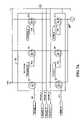
- FIGS. 7A–7Bare schematic diagrams and plan view of a portion of the motor control system of FIG. 1 including a transistor power bridge circuit;
- FIG. 8is a schematic diagram of a portion of the motor control system of FIG. 1 including motor current sensing amplifiers;
- FIGS. 9A–9Bare schematic diagrams of a portion of the motor control system of FIG. 1 including a power supply circuit
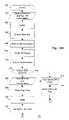
- FIGS. 10A–10Gare a flowchart diagram illustrating the steps for controlling a DC motor in accordance with the present invention.
- the present inventioncomprises a motor control system for controlling a brushless DC (BLDC) motor.
- Motor control system 20is capable of detecting a locked or stopped rotor 26 without a rotor position or speed sensor.
- the exemplary embodiment of motor control system 20generally includes electric motor 22 , transistor power bridge circuit 30 , phase driver circuit 32 , motor control circuit 38 , and protection/fault detection circuit 42 .
- Electric motor 22 in the exemplary embodimentis a BLDC motor having three phase coils, phase A 24 a , phase B 24 b , and phase C 24 c .
- the plurality of phase coils 24 a – 24 care driven by transistor power bridge circuit 30 , including phase source driving FETs Q 2 , Q 6 , and Q 10 , and phase sink driving FETs Q 3 , Q 9 , and Q 11 .
- Transistor power bridge circuit 30is controlled by motor control circuit 38 , including motor control IC 40 , which may be a commercially available, off-the-shelf motor control IC having a control input for selectively enabling or disabling phase driver outputs.
- the control inputmay be a port for disabling the phase driver outputs in the event of a current overload.
- motor control IC 40provides aspects of motor control, including start-up, phase locked electronic commutation, and speed detection for motor 22 .
- Electronic commutationis provided by sensorless phase detection, for example, by detecting signal zero crossing for the undriven phase.
- Motor control IC 40may be a variable speed motor controller capable of handling the high torque and low to high speed ramping required for operating compressors, pumps, and such.
- Motor control IC 40includes a control input for selectively enabling and disabling the driving of transistor power bridge circuit 30 .
- Power bridge circuit 30powers phase coils 24 a – 24 c of motor 22 . Therefore, switching the control input selectively enables and disables power of phase coils 24 a – 24 c .
- the control input statemay be momentarily switched for back EMF detection and also switched to disable motor 22 in the event a fault requiring system protection is detected.
- Fault detection circuit 42includes optically coupled isolators U 14 and U 15 for coupling phase coils 24 a , 24 b , and 24 c to back EMF sensing capacitor C 7 .
- Microcontroller 44provides control and locked and stopped rotor detection by selectively driving the control input of motor control IC 40 to its enabled state and measuring back EMF across capacitor C 7 .
- the exemplary embodiment of motor controller 20includes several other fault detection devices coupled to protection circuit 42 .
- Shell temperature sensor 29may be thermally coupled to motor 22 or compressor 28 for detecting an over-temperature condition.
- Power bridge temperature sensor 31may be thermally coupled to transistor power bridge 30 for detecting over-temperature of transistors Q 2 , Q 3 , Q 6 , Q 9 , Q 10 , and Q 11 .
- Voltage sensing circuit 52may be coupled to power supply 34 for sensing a voltage supply level that is over or under preset thresholds.
- Current sensing circuits 60 and 62may be coupled to at least one phase coil 24 a – 24 c for sensing a motor supply current above or below preset thresholds.
- microcontroller 44may not only detect faults, but may also perform protection and diagnostic functions. For example, microcontroller 44 may shut down motor 22 after detecting a preset number of faults or the fault continuing for more than a preset time. Additionally, by detecting the fault type or the combination of faults and whether resuming normal functioning of motor 22 , if attempted, was successful, microcontroller 44 may indicate the likely underlying source of the fault condition. For example, microcontroller 44 may include a look-up table (not shown) in order to perform such diagnostic functions.
- FIG. 2a block diagram of exemplary motor control system 20 is shown powering motor 22 , which drives compressor 28 .
- Motor 22 and compressor 28are hermetically sealed in housing 27 and may be, for example, part of a refrigeration system.
- the load driven by motor 22 in the exemplary embodimentis a compressor, the present invention can be used to control a motor or other electrical actuator driving a wide range of loads, for example, fluid pumps, such as liquid and gas, valves, etc.
- low current phase drivers 32are coupled to motor control circuit 38 and provide reference signals for transistor power bridge circuit 30 .
- Power for motor control system 20is provided by switching power supply 34 .
- System protection elementsinclude power bridge temperature sensor 31 and shell temperature sensor 29 .
- Power bridge temperature sensor 31is thermally coupled to the high-power components of transistor power bridge circuit 30 , for example, thermally mounted to heat sink 56 ( FIG. 7A ).
- Power bridge temperature sensor 31is electrically coupled to microcontroller 44 , thereby providing thermal monitoring and motor shutdown capability in the event transistor power bridge circuit 30 overheats.
- shell temperature sensor 29is thermally coupled to at least one of motor 22 and compressor 28 , for example, thermally mounted to housing 27 .
- Shell temperature sensor 29for example a bimetal switch, is similarly coupled to microcontroller 44 , thereby providing thermal monitoring and motor 22 shutdown capability in the event of motor 22 or compressor 28 reaching an operating temperature that may cause system damage.
- protection/fault detection circuit 42includes microcontroller 44 , which includes input and output (IO) ports, analog-to-digital (A/D) converters, and software for controlling fault detection, diagnostic functions, system protection, and motor shutdown; power bridge temperature detection sensor 31 ( FIG. 7B ); motor voltage sensing circuit 52 ; and back EMF detection circuit 54 ( FIG. 4B ).
- microcontroller 44includes input and output (IO) ports, analog-to-digital (A/D) converters, and software for controlling fault detection, diagnostic functions, system protection, and motor shutdown; power bridge temperature detection sensor 31 ( FIG. 7B ); motor voltage sensing circuit 52 ; and back EMF detection circuit 54 ( FIG. 4B ).
- Microcontroller 44includes software for measuring various motor conditions, detecting faults, making diagnostic determinations, and providing system protection to stop, restart, or shut down motor 22 by providing a control input to motor control IC 40 .
- microcontroller 44receives +5 V DC power at pin 1 , circuit ground at pin 8 , a back EMF signal from detection circuit 54 ( FIG. 4B ) at pin 4 , motor supply current from motor current sensing amp 60 ( FIG. 8 ) at pin 7 , motor supply voltage from motor voltage sensing circuit 52 at pin 5 , motor speed from motor control IC 40 at pin 11 , shell temperature fault detection at pin 23 , and temperature measurement from power bridge temperature sensor 31 at pin 3 .
- microcontroller 44provides IO ports at pin 26 for disabling the phase driver output of motor control IC 40 , at pin 14 for fault indication output, at pin 22 to select ramp mode of motor control IC 40 , at pin 25 to reset motor control IC 40 , at pin 13 to provide speed signal VSPEED to motor control IC 40 , and at pins 15 and 16 for pre-motor start charging of network motor compensation capacitors C 17 and C 45 .
- Microcontroller 44may be, for example, Part No. 16F870 available from Microchip Technology Inc. of Chandler, Ariz. Microcontroller 44 is enabled by software, such as represented by the flowcharts of FIGS. 10A–10G . Alternatively, microcontroller 44 may alternatively comprise an alternative logic processing device, such as a microprocessor, digital signal processor, or discrete circuitry.
- Pin 3 of microcontroller 44is an A/D converter input port which receives temperature signal TEMP_OUT from power bridge temperature sensor circuit 31 ( FIG. 7B ).
- power bridge temperature detection circuit 31receives a temperature signal from pin 2 of temperature sensor U 3 , which is thermally coupled to, power bridge FETs Q 2 , Q 3 , Q 6 , Q 9 , Q 10 , and Q 11 .
- sensor U 3maybe mounted on heat sink 56 .
- Temperature sensor U 3may be, for example, Part No. LM34TH, a precision Fahrenheit temperature sensor providing a linear millivolt signal proportional to degrees Fahrenheit, available from National Semiconductor of Santa Clara, Calif.
- temperature signal TEMP-OUT from temperature sensor U 3is provided to the input pin 3 and shell temperature sensing circuit 50 is coupled to pin 23 of microcontroller 44 . Therefore, when the temperature of heat sink 56 measured by temperature sensor U 3 exceeds a preset limit determined by microcontroller 44 , protective measures, such as temporary shutdown of motor 22 may be executed by microcontroller 44 .
- Shell temperature sensor 29may be coupled by connector JP 4 to shell temperature sensing circuit 50 , including resistors R 3 , R 4 , R 20 , and R 24 , transistor Q 7 , capacitor C 50 , and diode D 2 .
- shell temperature sensing circuit 50switches on transistor Q 7 , providing a signal through diode D 2 for driving ISENSE control input pin 1 of motor control IC 40 ( FIG. 4C ) to a high logic state to disable the phase driver outputs.
- a signalis also provided by Q 7 for driving temperature fault IO pin 23 of microcontroller 44 to a high logic state to indicate an over-temperature fault.
- microcontroller 44may provide a fault output signal at pin 14 indicating a fault condition via pin 8 of external controller interface JP 1 .
- microcontroller 44may stop motor 22 by providing an active high output signal at motor disable output pin 26 of microcontroller 44 , which is coupled with ISENSE input pin 1 of motor controller IC 40 , thus disabling the phase driver outputs of motor controller IC 40 .
- Motor voltage sensing circuit 52includes resistors R 46 , R 16 , and R 12 that divide the motor supply voltage and are coupled with microcontroller 44 pin 5 . Additionally, zener diode D 4 protects microcontroller 44 from damaging levels of voltage. Motor voltage input pin 5 is an A/D converter that measures the motor supply voltage and can detect an over-voltage or an under-voltage condition. Microcontroller 44 may shut down motor 22 in an over-voltage condition to prevent damage to motor 22 , motor control system 20 , or other connected system components. Microcontroller 44 may also shut down motor 22 in the event of an under-voltage condition, for example, for battery-driven systems so that remaining battery power is available for monitoring and controlling functions and not entirely expended by driving motor 22 .
- Motor current input pin 7 of microcontroller 44is an A/D converter that may be configured to provide current sensing over or under preset limits.
- motor current sensing amplifier 60receives a 0.25 mV/A signal from circuit node 64 ( FIG. 7B ) between the source terminals of phase driver sink FETs Q 3 , Q 9 , and Q 11 and low resistance, high power resistors R 43 and R 44 , which are connected to ground.
- Op amp U 8 Bamplifies the signal and is configured for a fixed gain of 50, which scales the signal to utilize the 5 volt range of microcontroller 44 A/D converter at pin 7 .
- microcontroller 44can detect failure modes other than a locked or stopped rotor, such as a short in phase coils 24 a – 24 c.
- pin 4 of microcontroller 44is an A/D converter for measuring motor back EMF, which is generated across capacitor C 7 ( FIG. 4B ) by phase coils 24 a – 24 c during a periodic sampling controlled by microcontroller 44 .
- motor control IC 40momentarily disables the phase driver outputs at pins 2 – 4 and 9 – 11 ( FIG. 4C ) of motor controller IC 40 so that phase coils 24 a – 24 c operate as a generator if rotor 26 ( FIG. 2 ) of motor 22 is still in rotation relative to the motor stator windings, i.e., the phase coils 24 a – 24 c .
- the phase driver outputsare disabled by motor disable output pin 26 of microcontroller 44 , which is coupled through resistor R 13 and diode D 3 ( FIG. 4B ), driving ISENSE control input pin 1 of motor control IC 40 to a high logic state.
- back EMF detection circuit 54includes optically coupled isolators U 14 and U 15 , which are connected through resistors R 6 , R 8 , R 32 , R 33 , R 39 , and R 45 to motor phases coils 24 a – 24 c .
- Motor disable output pin 26 of microcontroller 44also provides a supply voltage to the output transistors of optically coupled isolators U 14 and U 15 .
- the output transistors of U 14 and U 15charge capacitor C 7 when they are excited by the LEDs.
- the LEDsare internal to U 14 and U 15 , and are powered by back EMF received from motor 22 phase coils 24 a – 24 c .
- Optically coupled isolators U 14 and U 15maybe, for example, Part No. PS2505-1 manufactured by NEC Corporation of Melville, N.Y.
- the exemplary embodiment motor control circuit 38 for controlling motor 22is primarily implemented by motor control IC 40 , such as Part No. ML4425CS available from Fairchild Semiconductor Corporation of South Portland, Me.
- Motor control IC 40provides pulse width modulated (PWM) ramp and speed control for BLDC motor 22 .
- PWMpulse width modulated
- FIGS. 4A and 4Cmotor control IC 40 requires a number of associated components that are selected based on the motor type, voltage, application, etc., and in accordance with the manufacturer's specifications.
- the run speed of motor 22is determined by a speed signal provided through external control interface JP 1 pin 7 , shown in FIG. 3A , and received by A/D converter input pin 2 of microcontroller 44 .
- Resistors R 1 and R 5 and capacitor C 1also shown in FIG. 3A , condition the speed signal. Based on this signal and control and protection logic of microcontroller 44 , IO port pin 13 of microcontroller 44 provides speed command signal VSPEED, conditioned by resistors R 7 and R 11 and capacitors C 44 and C 46 , to pin 8 of motor control IC 40 .
- motor control IC 40uses back EMF detection on the undriven phase coil 24 a – 24 c received through pins 22 – 24 , shown in FIGS. 4A and 4C .
- Motor control IC 40drives phase driver outputs pins 2 – 4 and 9 – 11 to power motor phase coils 24 a – 24 c in a sequence providing phase locked loop (PLL) electronic commutation of motor 22 , and ramping up to a motor run speed determined by the speed command signal VSPEED received at pin 8 .
- Pin 13provides speed feedback signal VCO/TACH to external controller interface JP 1 pin 5 , shown in FIG. 3A , and to IO port pin 11 of microcontroller 44 , based on the PLL commutation of motor controller IC 40 .
- PLLphase locked loop
- microcontroller 44may determine if the motor speed is under a minimum preset motor speed or over a maximum preset motor speed. For example, the inventors have realized that in hermetically sealed compressor applications such as the exemplary embodiment, motor RPM of less than a preset minimum speed determined for each compressor application is insufficient to properly lubricate compressor 28 , for example, less than 1500 RPM. Therefore, if a fault condition causes motor 22 to fall below the preset speed for a preset period of time, microcontroller 44 can flag a fault condition and shut motor 22 down. Similarly, the inventors have realized that operation of motor 22 at an RPM of over a preset maximum speed may cause damage to valve components of compressor 28 , for example, over 6500 RPM. Similarly, the over-speed fault can be determined and operation of motor 22 stopped to prevent system damage.
- three sourcesprovide logic inputs to ISENSE control input pin 1 of motor control IC 40 .
- Motor disable output pin 26 of microcontroller 44drives motor current overload ISENSE input pin 1 of motor control IC 40 to a high logic state for periodic sampling of motor 22 back EMF in order to detect a locked or stopped rotor.
- periodic samplingincludes driving ISENSE pin 1 high for about 1.0 msec, about once each second, for example, to detect whether the rotor of motor 22 has stopped due to a locked or stopped rotor condition.
- the running of motor 22will provide back EMF, which charges capacitor C 7 and, after a preset delay, for example, about 0.9 msec., is measured by back EMF A/D converter at pin 4 of microcontroller 44 , shown in FIGS. 3A and 3B .
- back EMFwill not be generated by phase coils 24 a – 24 c and capacitor C 7 will not be charged, so voltage below a preset motor running threshold will be detected at pin 4 .
- Microcontroller 44may then provide a control signal to motor current overload ISENSE pin 1 of motor control IC 40 and provide a fault output signal at pin 4 of microcontroller 44 .
- An input signal to motor current overload ISENSE pin 1 of motor control IC 40is also provided by shell temperature sensor circuit 50 , shown in FIG. 3C , which drives ISENSE pin 1 to a high state in the event shell temperature switch 29 opens, removing continuity to ground and allowing pin 1 to float to 5V, for example, by the opening of bimetal switch 29 in the event of an over-temperature condition.
- a control signal coupled to ISENSE pin 1 of motor control IC 40may also be provided by motor current sensing amplifier 62 shown in FIG. 8 .
- Motor current sensing amplifier 62receives and amplifies a 0.25 mV/A signal across current sense resistors R 43 and R 44 and from the source terminals of sink FETs Q 3 , Q 9 , and Q 11 of transistor power bridge circuit 30 .
- Motor current sensing amplifier 62provides a signal gain of 5 and is coupled to ISENSE pin 1 of motor control IC 40 .
- the signal gain of amplifier 62is selected to provide quick ISENSE pin 1 signal switching to prevent damage to power bridge circuit 30 in the event motor current exceeds a preset threshold.
- high-side phase driver outputs from pins 2 – 4 of motor control IC 40drive low current single channel drivers U 1 , U 6 , and U 9 .
- Drivers U 1 , U 6 , and U 9drive the gate terminals of source FETs Q 2 , Q 6 , and Q 10 , shown in FIGS. 7A and 7B , to follow.
- Low current drivers U 1 , U 6 , and U 9may be, for example, Part No. IR2118S manufactured by International Rectifier of El Segundo, Calif.
- low-side phase driver outputs pin 9 – 11 of motor control IC 52drive low current single output drivers U 4 , U 7 , and U 11 , which drive the gate terminals of sink FETs Q 3 , Q 9 , and Q 11 , shown in FIGS. 7A and 7B , of transistor power bridge circuit 30 .
- Low current drivers U 4 , U 7 , and U 11may be, for example, Part No. TC442COA manufactured by Microchip Technology Inc. of Chandler, Ariz.
- phase coil power driver FETs Q 2 , Q 3 , Q 6 , Q 9 , Q 10 , and Q 11are thermally coupled to heat sink 56 and provide high-side and low-side switching for phase coils 24 a – 24 c of motor 22 .
- Temperature sensor U 3is also thermally coupled with heat sink 56 , and provides a temperature signal to power bridge temperature sensor circuit 31 , which is coupled to IO pin 3 of microcontroller 44 ( FIGS. 3A and 3B ), for sensing an over-temperature condition in transistor power bridge circuit 30 , as discussed above.
- switching power supply 34receives a DC input voltage through external control interface connector JP 1 pin, for example, in the range of 8 to 30 VDC.
- Voltage regulators U 12 and U 10 as well as other conditioning and protection componentsprovide power, for example, regulated 12 V and 5 V supplies for motor control system 20 .
- FIGS. 10A–10Gshow an exemplary flowchart illustrating steps for monitoring and controlling motor control system 20 , including detecting locked rotor, stopped rotor, high or low voltage, high or low current, over-temperature, and over and under speed conditions.
- methods 200 and 300are provided in the form of software enabling microcontroller 44 .
- Subroutine 200commences at step 202 and is an exemplary embodiment of the method and apparatus for motor control according to the present invention.
- step 202microcontroller 44 initializes the internal interrupts, A/D converters, and clock, and clears the registers.
- step 204microcontroller 44 clears the internal fault flags, for example, over current, over temperature, and locked or stopped rotor.
- microcontroller 44measures the motor voltage provided to A/D converter at pin 5 .
- microcontroller 44checks the logic state of temperature fault input pins 3 and 23 .
- microcontroller 44drives IO pins 16 and 15 high and low, respectively, to precharge motor compensation network capacitors C 17 and C 45 to a normal run state, substantially eliminating motor 22 RPM overshoot on power-up.
- microcontroller 44turns on motor 22 by providing a low logic output at motor disable pin 26 , which is coupled to ISENSE pin 1 of motor control IC 40 .
- microcontroller 44delays for a preset period of time, for example, 2 seconds, while motor control IC 40 ramps the speed of motor 22 up to the commanded operating speed.
- step 214microcontroller 44 determines if a preset period of one second time, for example, has expired for periodic motor control system status check. If the preset period has elapsed, step 216 is completed. If one second has not elapsed, step 218 is completed. On initial execution of subroutine 200 , the preset period will not have elapsed when step 214 is first completed, so step 218 will be completed to determine if motor 22 is running. If, at step 218 , microcontroller 44 determines motor 22 is running, subroutine 200 continues at step 214 . If microcontroller 44 determines the motor is not running, then subroutine 200 continues at step 204 in order to again check parameters and attempt motor start.
- subroutine 300which is also an exemplary embodiment of the methods and apparatus for motor control according to the present invention, is completed.
- subroutine 300which checks the status of motor control system 20 and provides diagnostics, fault detection and protection for system 20 , begins at step 302 .
- microcontroller 44disables internal interrupts and drives motor disable output pin 26 to a high state to disable phase driver outputs of motor control IC 40 and to provide back EMF detection across capacitor C 7 .
- microcontroller 44delays, for example, for 0.9 msec. The delay provides time for back EMF to be generated if motor 22 is running, and to charge capacitor C 7 .
- microcontroller 44enables internal interrupts.
- microcontroller 44converts the voltage present at A/D converter pin 4 to digital form.
- microcontroller 44reads the digital result of the voltage measured across capacitor C 7 .
- microcontroller 44returns motor disable output pin 26 to its low state so that motor control IC 40 will again drive phase driver outputs for powering and commutating motor 22 .
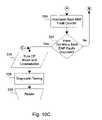
- step 314microcontroller 44 determines whether back EMF is present, i.e., the rotor of motor 22 is still in rotation and therefore the rotor is not locked and motor control IC 40 has not lost rotor phase lock. If in step 314 microcontroller 44 determines back EMF is present, step 316 will be completed, else step 322 will be completed. If back EMF is not present and step 322 is completed, microcontroller 44 will turn off motor 22 by driving motor disable output pin 26 high to disable phase driver outputs of motor control IC 40 .
- step 324microcontroller 44 resets a motor run time clock.
- step 326microcontroller 44 will delay, for example, for 10 seconds, before attempting to restart motor 22 .
- step 328motor controller 44 sets the back EMF fault bit in the internal status register of microcontroller 44 .
- microcontroller 44increments a back EMF fault counter.
- microcontroller 44determines whether the back EMF fault counter has exceeded a preset limit. If in step 332 , microcontroller 44 determines that too many back EMF faults have occurred, step 334 will be completed, else step 316 , shown in FIG. 10B , is completed.
- step 334microcontroller 44 turns off motor 22 by setting motor disable output pin 26 low to disable phase driver output of motor control IC 40 .
- step 336because of excess faults, microcontroller 44 is capable of completing diagnostic tests and/or determinations based on fault conditions to determine to underlying system problem, for example, low refrigerant, and whether to attempt restart or a back-up mode of operation, thus protecting system components from damage.
- step 338subroutine 300 ends and returns to step 216 of subroutine 200 , shown in FIG. 10A .
- step 316microcontroller 44 resets the back EMF fault bit in the internal status register of microcontroller 44 .
- step 318microcontroller 44 resets the back EMF flag internal to microcontroller 44 .
- step 340analog-to-digital conversion of the motor voltage supplied to pin 5 of microcontroller 44 is completed.
- step 342microcontroller 44 determines whether the motor voltage is above a preset threshold. If the voltage is high, step 354 will be completed, else step 344 is completed.
- step 344microcontroller 44 determines if motor 22 is running. If motor 22 is running, step 352 will be completed, else step 346 is completed. If motor 22 is not running, in step 346 , microcontroller 44 determines whether there is a start-up under-voltage condition, i.e., motor voltage supplied to pin 5 is below a preset threshold. If an under-voltage condition is present, step 354 is completed, else step 348 is completed.
- step 348microcontroller 44 resets the voltage status bit. After step 348 is completed, subroutine 300 continues at step 364 , shown in FIG. 10E .
- step 344determines motor 22 is running, step 352 is completed. In step 352 , microcontroller 44 determines whether there is an under-voltage condition. If an under-voltage condition exists, step 354 is completed, else step 348 is completed. In step 354 , microcontroller 44 determines whether the voltage fault bit in the status register of microcontroller 44 is set. If the voltage fault bit is set, step 362 is completed, else step 356 is completed.
- microcontroller 44sets the voltage fault status bit in the status register of microcontroller 44 .
- microcontroller 44turns off motor 22 by driving motor disable output pin 26 low, thereby disabling phase driver outputs of motor control IC 40 .
- microcontroller 44increments the voltage fault count.
- microcontroller 40delays, for example, for 10 seconds, before repeating a portion of the motor control system status check beginning at step 340 .
- microcontroller 44determines whether a thermal overload condition exists, i.e., the presence of a temperature fault signal at pin 23 or a temperature signal greater than a preset threshold at pin 3 . If so, step 366 is completed, else step 378 is completed. In step 366 , motor 22 is turned off by microcontroller 44 driving motor disable output pin 26 low, thereby disabling phase driver outputs of motor control IC 40 . In step 368 , microcontroller 44 sets the thermal fault status bit. In step 370 , microcontroller 44 increments a thermal fault counter. In step 372 , microcontroller 44 determines whether the thermal fault counter has exceeded a preset limit. If so, subroutine 300 continues at step 334 , shown in FIG. 10C . If the thermal fault counter has not exceeded a preset limit, step 374 is completed.
- a thermal overload conditionexists, i.e., the presence of a temperature fault signal at pin 23 or a temperature signal greater than a preset threshold at pin 3 . If so, step
- step 374microcontroller 44 delays, for example, for 5 seconds, to allow system cooling before again checking temperature signal inputs.
- microcontroller 44determines whether a temperature fault signal is received at pins 3 or 23 . If so, step 374 will again be completed to provide further cooling delay. If a thermal overload condition is not detected, step 378 is completed. In step 378 , microcontroller 44 resets the temperature fault status bit.
- step 380microcontroller 44 determines whether a motor current supply signal received at pin 7 of microcontroller 44 is greater than a preset maximum current limit or less than a preset minimum current limit. If a preset current limit has been exceeded, then step 384 is completed, else step 382 is completed. In step 384 , microcontroller 44 sets the current fault status bit. In step 386 , microcontroller 44 increments a current fault counter. In step 388 , microcontroller 44 determines whether the current fault counter has exceeded a preset limit. If so, subroutine 300 continues at step 334 , shown in FIG. 10C . If the current fault counter has not exceeded the preset limit, step 390 is completed.
- step 390microcontroller 44 delays, for example, for 2 seconds, before checking motor supply current again.
- step 390subroutine 300 continues at step 382 once again check current limits. If in step 380 a current limit was not exceeded, in step 382 microcontroller 44 resets the current fault bit and subroutine 300 continues at step 392 , shown in FIG. 10G .
- step 392microcontroller 44 determines whether the motor speed signal received at pin 11 of microcontroller 44 is greater than a preset maximum speed limit or less than a preset minimum speed limit. If a preset limit has been exceeded, step 398 is completed, else step 394 is completed. In step 398 , microcontroller 44 sets the speed fault status bit. In step 400 , microcontroller 44 increments a speed fault counter. In step 402 , microcontroller 44 determines whether the speed fault counter has exceeded a preset limit. If so, subroutine 300 continues at step 334 , shown in FIG. 10C . If the speed fault counter has not exceeded a preset limit, step 404 is completed.
- step 404microcontroller 44 delays, for example, for 2 seconds, before subroutine 300 continues at step 392 to again check motor speed. If in step 392 a preset motor speed limit was not exceeded, then in step 394 microcontroller 44 resets the speed fault bit. In step 396 , subroutine 300 is completed and returned to step 216 of subroutine 200 , as shown in FIG. 10A .
Landscapes
- Engineering & Computer Science (AREA)
- Power Engineering (AREA)
- Mechanical Engineering (AREA)
- General Engineering & Computer Science (AREA)
- Computer Hardware Design (AREA)
- Control Of Motors That Do Not Use Commutators (AREA)
Abstract
Description
| TABLE 1 | |||
| Component | Value/Part No. | ||
| C1 | 10 | μF | |
| C10 | .1 | μF | |
| C11 | 1000 | μF | |
| C12 | .22 | μF | |
| C13 | .1 | μF | |
| C14 | .22 | μF | |
| C15 | 470 | pF | |
| C16 | 3300 | μF | |
| C17 | 2.2 | μF | |
| C18 | 1000 | pF | |
| C19 | 4.7 | μF | |
| C2 | 10 | μF | |
| C20 | 4.7 | μF | |
| C21 | 10 | μF | |
| C22 | 4700 | pF | |
| C23 | .1 | μF | |
| C24 | .1 | μF | |
| C25 | 1000 | μF | |
| C26 | .22 | μF | |
| C27 | .1 | μF | |
| C28 | 2.2 | μF | |
| C29 | 470 | PF | |
| C3 | 220 | μF | |
| C30 | .1 | μF | |
| C31 | 1000 | μF | |
| C32 | 4.7 | μF | |
| C33 | 10 | μF | |
| C34 | 100 | μF | |
| C35 | .1 | μF | |
| C36 | 15 | μF | |
| C36 | 15 | μF | |
| C37 | .1 | μF | |
| C38 | 1000 | μF | |
| C39 | .1 | μF | |
| C4 | .1 | μF | |
| C40 | 330 | μF | |
| C41 | 2200 | μF | |
| C42 | 220 | μF | |
| C43 | 220 | μF | |
| C44 | .1 | μF | |
| C45 | 4.75 | μF | |
| C46 | .1 | μF | |
| C47 | 15 | pF | |
| C48 | 15 | pF | |
| C49 | .1 | μF | |
| C50 | 1 | μF | |
| C52 | .1 | μF | |
| C5 | 1000 | μF | |
| C6 | 4.7 | μF | |
| C7 | .1 | μF | |
| C8 | 10 | μF | |
| C9 | 10 | μF |
| D1 | S1JDICT | |
| D10 | ZM4743ACT 13V | |
| D11 | B260 DICT | |
| D12 | ES1DDICT | |
| D13 | SA36A | |
| D14 | B260DIC | |
| D2 | SS16GI | |
| D3 | SS16GI | |
| D4 | MMS2 | |
| D5 | SS16GI | |
| D6 | SS16GI | |
| D8 | S1JDIC | |
| D9 | S1JDICT | |
| F1 | RXE050 0.5A | |
| F2 | RXE050 0.5A | |
| F3 | RXE020 02.A |
| L1 | 150 | mH | |
| L2 | 100 | μH | |
| L3 | 10 | mH |
| P1 | Q4435-B | ||
| Q10 | IRFP2907 | ||
| Q11 | IRFP2907 | ||
| Q2 | IRFP2907 | ||
| Q3 | IRFP2907 | ||
| Q5 | FMMT3904CT | ||
| Q6 | IRFP2907 | ||
| Q7 | FMMT3904CT | ||
| Q9 | IRFP2907 | ||
| R1 | 10K | ||
| R10 | 16.2K | ||
| R11 | 10K | ||
| R12 | 1.21K | ||
| R13 | 100K | ||
| R14 | 100K | ||
| R15 | 10K | ||
| R16 | 8.2K | ||
| R17 | 22.1 | ||
| R18 | 137K | ||
| R19 | 100K | ||
| R2 | 10K | ||
| R20 | 499 | ||
| R21 | 140K | ||
| R22 | 80.6K | ||
| R23 | 47.5 | ||
| R24 | 1K | ||
| R25 | 16.2K | ||
| R26 | 10K | ||
| R27 | 1.00K | ||
| R28 | 1.5K | ||
| R29 | 1.00K | ||
| R3 | 4.75K | ||
| R30 | 22.1 | ||
| R31 | 1.00K | ||
| R32 | 1.1K | ||
| R33 | 1.1K | ||
| R34 | 48.7K | ||
| R35 | 10K | ||
| R36 | 47.5 | ||
| R37 | 2.2K | ||
| R38 | 16.2K | ||
| R39 | 1.1K | ||
| R40 | 10.5K | ||
| R41 | 22.1 | ||
| R42 | 1.21K | ||
| R43 | .010 2W | ||
| R44 | .010 2W | ||
| R45 | 1.1K | ||
| R46 | 8.2K | ||
| R47 | 16.2K | ||
| R48 | 16.2K | ||
| R49 | 16.2K | ||
| R5 | 10K | ||
| R50 | 75 | ||
| R51 | 1.5K 3W | ||
| R52 | 1.5K 3W | ||
| R53 | 1.5K 3W | ||
| R54 | 100 | ||
| R55 | 2.2K | ||
| R56 | 4.75K | ||
| R6 | 1.1KK | ||
| R7 | 10K | ||
| R8 | 1.1K | ||
| R9 | 47.5 | ||
| U1 | IR2118S | ||
| U10 | NJM78L05VA | ||
| U11 | TC4420C0A | ||
| U12 | 2576HVT-ADJ | ||
| U13 | 74AHCIG04DBV | ||
| U14 | PS2505-1 | ||
| U15 | PS2505-1 | ||
| U2 | PIC16F870 | ||
| U3 | LM34DH | ||
| U4 | TC4420COA | ||
| U5 | ML4425CS | ||
| U6 | IR2118S | ||
| U7 | TC4420C0A | ||
| U8 | LMC6062AIM | ||
| U9 | IR2118S | ||
Claims (39)
Priority Applications (1)
| Application Number | Priority Date | Filing Date | Title |
|---|---|---|---|
| US10/763,452US7042180B2 (en) | 2003-01-24 | 2004-01-23 | Brushless and sensorless DC motor control system with locked and stopped rotor detection |
Applications Claiming Priority (2)
| Application Number | Priority Date | Filing Date | Title |
|---|---|---|---|
| US44264803P | 2003-01-24 | 2003-01-24 | |
| US10/763,452US7042180B2 (en) | 2003-01-24 | 2004-01-23 | Brushless and sensorless DC motor control system with locked and stopped rotor detection |
Publications (2)
| Publication Number | Publication Date |
|---|---|
| US20050029976A1 US20050029976A1 (en) | 2005-02-10 |
| US7042180B2true US7042180B2 (en) | 2006-05-09 |
Family
ID=35006325
Family Applications (1)
| Application Number | Title | Priority Date | Filing Date |
|---|---|---|---|
| US10/763,452Expired - LifetimeUS7042180B2 (en) | 2003-01-24 | 2004-01-23 | Brushless and sensorless DC motor control system with locked and stopped rotor detection |
Country Status (6)
| Country | Link |
|---|---|
| US (1) | US7042180B2 (en) |
| EP (1) | EP1586160A2 (en) |
| CN (1) | CN1742427A (en) |
| BR (1) | BRPI0406949A (en) |
| CA (1) | CA2513550A1 (en) |
| WO (1) | WO2004068693A2 (en) |
Cited By (96)
| Publication number | Priority date | Publication date | Assignee | Title |
|---|---|---|---|---|
| US20050218815A1 (en)* | 2004-03-30 | 2005-10-06 | Mitsubishi Denki Kabushiki Kaisha | Power generation controller of vehicle power generator |
| US20050254273A1 (en)* | 2004-03-30 | 2005-11-17 | Christophe Soudier | Method, apparatus and article for bi-directional DC/DC power conversion |
| US20060164767A1 (en)* | 2005-01-27 | 2006-07-27 | Delta Electronics, Inc. | Brushless DC motor drive apparatus |
| US20060244333A1 (en)* | 2005-04-29 | 2006-11-02 | Young-Chun Jeung | Two-phase brushless DC motor |
| US7245098B1 (en)* | 2006-03-22 | 2007-07-17 | Sononwealth Electric Machine Industry Co., Ltd. | Brushless dc motor having a motor-locked protective circuit |
| US20080055799A1 (en)* | 2006-08-31 | 2008-03-06 | Yazaki Corporation | Apparatus and method for detecting abnormal conditions of a motor |
| US20080218113A1 (en)* | 2007-03-08 | 2008-09-11 | Ami Semiconductor Belgium Bvba | Output Contact for Feedback in Integrated Circuit Motor Driver |
| US20080239594A1 (en)* | 2007-03-26 | 2008-10-02 | Sanyo Electric Co., Ltd. | Motor Lock Detection Circuit |
| US20080255577A1 (en)* | 2007-04-11 | 2008-10-16 | Downer David A | Lens Delivery System Cartridge and Method of Manufacture |
| US20080258663A1 (en)* | 2007-04-18 | 2008-10-23 | James Clay Walls | Brushed motor controller using back EMF for motor speed sensing, overload detection and pump shutdown, for bilge and other suitable pumps |
| US20080286134A1 (en)* | 2007-05-16 | 2008-11-20 | Steven Regalado | Submersible pumping systems and methods for deep well applications |
| US20080297011A1 (en)* | 2007-06-01 | 2008-12-04 | Delaney Daniel E | Integrated controller/motor with thermal overload sensor |
| US20080313884A1 (en)* | 2007-05-11 | 2008-12-25 | Young-Chun Jeung | Method of making rotor of brushless motor |
| US20080315691A1 (en)* | 2007-05-11 | 2008-12-25 | Young-Chun Jeung | Rotor of brushless motor |
| US20090021204A1 (en)* | 2004-10-21 | 2009-01-22 | Shop-Vac Corporation | Method and apparatus for thermal sensing in an electrically commutated motor |
| US20090137199A1 (en)* | 2007-11-28 | 2009-05-28 | Young-Chun Jeung | Method of constant rpm control for a ventilation system |
| US20090218971A1 (en)* | 2008-03-03 | 2009-09-03 | Sntech, Inc. | Phase logic circuits for controlling motors |
| US20090251085A1 (en)* | 2008-04-02 | 2009-10-08 | Minebea Co., Ltd. | Method and system for motor oscillatory state detection |
| US20090284201A1 (en)* | 2008-05-15 | 2009-11-19 | Young-Chun Jeung | Motor with magnetic sensors |
| US20100039058A1 (en)* | 2008-08-14 | 2010-02-18 | Young-Chun Jeung | Power drive of electric motor |
| US20100039055A1 (en)* | 2008-08-14 | 2010-02-18 | Young-Chun Jeung | Temperature control of motor |
| US20100094309A1 (en)* | 2008-10-13 | 2010-04-15 | Mikhail Boukhny | Automated Intraocular Lens Injector Device |
| US20100111709A1 (en)* | 2003-12-30 | 2010-05-06 | Emerson Climate Technologies, Inc. | Compressor protection and diagnostic system |
| US20100111706A1 (en)* | 2008-10-30 | 2010-05-06 | Bendix Commercial Vehicle Systems, Llc | High voltage bus capacitor pre-charger circuit |
| US20100115915A1 (en)* | 2007-02-14 | 2010-05-13 | Aircelle | Method for controlling electric motors of a thrust reverser |
| US20100177451A1 (en)* | 2009-01-09 | 2010-07-15 | Xiaohua Tang | Motor Overload Protecting Method |
| US20100187899A1 (en)* | 2007-07-30 | 2010-07-29 | Toyota Jidosha Kabushiki Kaisha | Pump control apparatus and brake control system |
| US20100253266A1 (en)* | 2009-04-02 | 2010-10-07 | Young-Chun Jeung | Brushless dc motor with soft-starting of pwm signals |
| US20100278518A1 (en)* | 2007-07-02 | 2010-11-04 | Smith & Nephew Plc | Measuring pressure |
| US20110031919A1 (en)* | 2009-08-10 | 2011-02-10 | Emerson Climate Technologies, Inc. | Controller and method for minimizing phase advance current |
| US20110270437A1 (en)* | 2010-05-03 | 2011-11-03 | Electronic Theatre Controls, Inc. | Performance venue with dynamic mechanical load management system and method |
| US8308799B2 (en) | 2010-04-20 | 2012-11-13 | Alcon Research, Ltd. | Modular intraocular lens injector device |
| US8330412B2 (en) | 2009-07-31 | 2012-12-11 | Thermo King Corporation | Monitoring and control system for an electrical storage system of a vehicle |
| US20130106334A1 (en)* | 2011-10-31 | 2013-05-02 | Yilcan Guzelgunler | Variable speed motor power de-rating (limiting) system and method for operating a motor with the same |
| US20130106331A1 (en)* | 2011-10-31 | 2013-05-02 | Yilcan Guzelgunler | Motor operation failure detection |
| US8579969B2 (en) | 2010-07-25 | 2013-11-12 | Alcon Research, Ltd. | Dual mode automated intraocular lens injector device |
| US8643216B2 (en) | 2009-07-31 | 2014-02-04 | Thermo King Corporation | Electrical storage element control system for a vehicle |
| US20140042952A1 (en)* | 2012-08-09 | 2014-02-13 | Samsung Electro-Mechanics Co., Ltd. | Apparatus and method for preventing sensing error in srm |
| US8657835B2 (en) | 2012-01-27 | 2014-02-25 | Alcon Research, Ltd. | Automated intraocular lens injector device |
| US8662620B2 (en) | 2011-11-21 | 2014-03-04 | Xerox Corporation | Indirect temperature monitoring for thermal control of a motor in a printer |
| US20140062364A1 (en)* | 2012-08-31 | 2014-03-06 | Melexis Technologies Nv | Method and apparatus for driving a sensorless bldc/pmsm motor |
| US20140097777A1 (en)* | 2012-10-04 | 2014-04-10 | Marvell World Trade Ltd. | Driving a rotating device based on a combination of speed detection by a sensor and sensor-less speed detection |
| US8801780B2 (en) | 2008-10-13 | 2014-08-12 | Alcon Research, Ltd. | Plunger tip coupling device for intraocular lens injector |
| US8808308B2 (en) | 2008-10-13 | 2014-08-19 | Alcon Research, Ltd. | Automated intraocular lens injector device |
| CN104135216A (en)* | 2014-08-22 | 2014-11-05 | 北京航空航天大学 | Fault tolerant topology structure of high-speed rotor inverter of magnetic suspension control torque gyroscope |
| US8894664B2 (en) | 2008-02-07 | 2014-11-25 | Novartis Ag | Lens delivery system cartridge |
| US8917037B2 (en) | 2010-01-14 | 2014-12-23 | Hitachi Koki Co., Ltd. | Electric operating machine |
| US8964338B2 (en) | 2012-01-11 | 2015-02-24 | Emerson Climate Technologies, Inc. | System and method for compressor motor protection |
| US8974573B2 (en) | 2004-08-11 | 2015-03-10 | Emerson Climate Technologies, Inc. | Method and apparatus for monitoring a refrigeration-cycle system |
| US8988019B2 (en) | 2010-01-14 | 2015-03-24 | Hitachi Koki Co., Ltd. | Electric operating machine |
| US8994306B2 (en) | 2012-05-25 | 2015-03-31 | Cirrus Logic, Inc. | System and method for isolating the undriven voltage of a permanent magnet brushless motor for detection of rotor position |
| US9000696B2 (en) | 2012-05-25 | 2015-04-07 | Cirrus Logic, Inc. | Circuit and method for sensorless control of a permanent magnet brushless motor during start-up |
| US9024561B2 (en) | 2012-05-25 | 2015-05-05 | Cirrus Logics, Inc. | Method and system for switching between different types of operation of a sensorless permanent magnet brushless motor at low or zero speed to determine rotor position |
| US9050399B2 (en) | 2007-07-02 | 2015-06-09 | Smith & Nephew Plc | Wound treatment apparatus with exudate volume reduction by heat |
| US9088232B2 (en) | 2009-08-10 | 2015-07-21 | Emerson Climate Technologies, Inc. | Power factor correction with variable bus voltage |
| US9088237B2 (en) | 2012-05-25 | 2015-07-21 | Cirrus Logic, Inc. | Circuit and method for calibration of sensorless control of a permanent magnet brushless motor during start-up |
| US9093941B2 (en) | 2012-05-25 | 2015-07-28 | Cirrus Logic, Inc. | Determining commutation position for a sensorless permanent magnet brushless motor at low or zero speed using an asymmetric drive pattern |
| US9121407B2 (en) | 2004-04-27 | 2015-09-01 | Emerson Climate Technologies, Inc. | Compressor diagnostic and protection system and method |
| US9154061B2 (en) | 2009-08-10 | 2015-10-06 | Emerson Climate Technologies, Inc. | Controller and method for transitioning between control angles |
| US9194894B2 (en) | 2007-11-02 | 2015-11-24 | Emerson Climate Technologies, Inc. | Compressor sensor module |
| US9192699B2 (en) | 2007-07-02 | 2015-11-24 | Smith & Nephew Plc | Silencer for vacuum system of a wound drainage apparatus |
| US9240749B2 (en) | 2012-08-10 | 2016-01-19 | Emerson Climate Technologies, Inc. | Motor drive control using pulse-width modulation pulse skipping |
| US9285802B2 (en) | 2011-02-28 | 2016-03-15 | Emerson Electric Co. | Residential solutions HVAC monitoring and diagnosis |
| US20160099560A1 (en)* | 2014-10-03 | 2016-04-07 | Seiko Epson Corporation | Circuit apparatus and electronic appliance |
| US9310439B2 (en) | 2012-09-25 | 2016-04-12 | Emerson Climate Technologies, Inc. | Compressor having a control and diagnostic module |
| US9310094B2 (en) | 2007-07-30 | 2016-04-12 | Emerson Climate Technologies, Inc. | Portable method and apparatus for monitoring refrigerant-cycle systems |
| EP2998753A3 (en)* | 2014-09-16 | 2016-05-04 | Brose Fahrzeugteile GmbH & Co. Kommanditgesellschaft, Würzburg | Monitoring device for an electric machine, control device and method |
| US9359937B2 (en) | 2010-03-31 | 2016-06-07 | Hitachi Koki Co., Ltd. | Two-cycle engine and engine tool comprising the same |
| RU2592264C2 (en)* | 2011-06-13 | 2016-07-20 | Спаль Аутомотиве С.Р.Л. | Electrically driven module |
| US9421092B2 (en) | 2009-02-11 | 2016-08-23 | Alcon Research, Ltd. | Automated intraocular lens injector device |
| US9425725B2 (en) | 2013-02-28 | 2016-08-23 | Cirrus Logic, Inc. | Position estimation system and method for an electric motor |
| US9480177B2 (en) | 2012-07-27 | 2016-10-25 | Emerson Climate Technologies, Inc. | Compressor protection module |
| CN106253761A (en)* | 2015-06-12 | 2016-12-21 | 半导体元件工业有限责任公司 | There is the electric machine controller of flexible protected mode |
| US9537416B2 (en) | 2014-11-28 | 2017-01-03 | General Electric Company | System and method for operating power converters |
| US9551504B2 (en) | 2013-03-15 | 2017-01-24 | Emerson Electric Co. | HVAC system remote monitoring and diagnosis |
| US9628002B2 (en) | 2013-03-13 | 2017-04-18 | Cirrus Logic, Inc. | Circuit and method for detecting missed commutation of a brushless DC motor |
| US9634593B2 (en) | 2012-04-26 | 2017-04-25 | Emerson Climate Technologies, Inc. | System and method for permanent magnet motor control |
| US9638436B2 (en) | 2013-03-15 | 2017-05-02 | Emerson Electric Co. | HVAC system remote monitoring and diagnosis |
| US9765979B2 (en) | 2013-04-05 | 2017-09-19 | Emerson Climate Technologies, Inc. | Heat-pump system with refrigerant charge diagnostics |
| US9823632B2 (en) | 2006-09-07 | 2017-11-21 | Emerson Climate Technologies, Inc. | Compressor data module |
| US9885507B2 (en) | 2006-07-19 | 2018-02-06 | Emerson Climate Technologies, Inc. | Protection and diagnostic module for a refrigeration system |
| WO2018075944A1 (en)* | 2016-10-21 | 2018-04-26 | Franklin Electric Co., Inc. | Motor drive system and method |
| US10075107B2 (en) | 2015-11-03 | 2018-09-11 | Nxp Usa, Inc. | Method and apparatus for motor lock or stall detection |
| US10188479B2 (en) | 2007-07-02 | 2019-01-29 | Smith & Nephew Plc | Carrying bag |
| US10241130B2 (en) | 2015-08-18 | 2019-03-26 | Microsemi SoC Corporation | Circuit and method to detect failure of speed estimation/speed measurement of a multi-phase AC motor |
| US10328187B2 (en) | 2007-07-02 | 2019-06-25 | Smith & Nephew Plc | Systems and methods for controlling operation of negative pressure wound therapy apparatus |
| US10425034B2 (en)* | 2016-04-21 | 2019-09-24 | Zhongshan Broad-Ocean Motor Co., Ltd. | Motor controller and electronically commutated motor comprising the same |
| US10447196B2 (en)* | 2014-02-27 | 2019-10-15 | Trw Limited | Motor bridge driver circuit |
| US10454263B2 (en) | 2014-10-01 | 2019-10-22 | Carrier Corporation | Compressor motor overload detection |
| US10488090B2 (en) | 2013-03-15 | 2019-11-26 | Emerson Climate Technologies, Inc. | System for refrigerant charge verification |
| US10523087B2 (en) | 2016-06-24 | 2019-12-31 | Black & Decker Inc. | Control scheme for operating cordless power tool based on battery temperature |
| US10617801B2 (en) | 2007-08-06 | 2020-04-14 | Smith & Nephew Plc | Canister status determination |
| US11233477B2 (en) | 2018-06-07 | 2022-01-25 | Ab Mikroelektronik Gesellschaft Mit Beschraenkter Haftung | Method and system for controlling an electric motor and detecting a stall condition |
| US11234360B2 (en) | 2019-02-01 | 2022-02-01 | Cnh Industrial Canada, Ltd. | Drive and sensing system for agricultural agitator |
| US20230327590A1 (en)* | 2021-03-19 | 2023-10-12 | BeiAng Air Tech Ltd. | Gear control circuit and system for alternating current motor, switch controller, and electronic device |
| US12121648B2 (en) | 2007-08-06 | 2024-10-22 | Smith & Nephew Plc | Canister status determination |
Families Citing this family (80)
| Publication number | Priority date | Publication date | Assignee | Title |
|---|---|---|---|---|
| DE502004012312D1 (en)* | 2003-06-06 | 2011-04-28 | Innolab Gmbh | PERISTALTIC |
| KR20050002627A (en)* | 2003-06-30 | 2005-01-07 | 마쯔시다덴기산교 가부시키가이샤 | Sensorless motor driving device and its driving method |
| JP4409313B2 (en)* | 2004-02-24 | 2010-02-03 | 株式会社デンソー | Brushless motor drive device |
| US7909805B2 (en) | 2004-04-05 | 2011-03-22 | Bluesky Medical Group Incorporated | Flexible reduced pressure treatment appliance |
| US10058642B2 (en) | 2004-04-05 | 2018-08-28 | Bluesky Medical Group Incorporated | Reduced pressure treatment system |
| US7321210B2 (en)* | 2005-04-05 | 2008-01-22 | International Rectifier Corporation | Sensorless brushless direct current motor drive using pulse width modulation speed control at motor frequency |
| US7053583B1 (en) | 2005-04-06 | 2006-05-30 | Delphi Technologies, Inc. | Brushless DC motor control |
| ES2564519T3 (en) | 2006-10-13 | 2016-03-23 | Bluesky Medical Group Inc. | Pressure control of a medical vacuum pump |
| JP4389975B2 (en)* | 2007-06-28 | 2009-12-24 | オムロン株式会社 | Safety systems and safety equipment |
| GB0712736D0 (en)* | 2007-07-02 | 2007-08-08 | Smith & Nephew | Apparatus |
| DE102007033152A1 (en)* | 2007-07-13 | 2009-01-15 | Robert Bosch Gmbh | For the diagnosis of a direct current motor, it runs as a generator during the diagnosis time for the induced voltage to be analyzed for faults |
| US8393169B2 (en) | 2007-09-19 | 2013-03-12 | Emerson Climate Technologies, Inc. | Refrigeration monitoring system and method |
| US20130096518A1 (en) | 2007-12-06 | 2013-04-18 | Smith & Nephew Plc | Wound filling apparatuses and methods |
| US11253399B2 (en) | 2007-12-06 | 2022-02-22 | Smith & Nephew Plc | Wound filling apparatuses and methods |
| WO2009134044A2 (en)* | 2008-04-29 | 2009-11-05 | Lg Electronics Inc. | Home appliance and home appliance system |
| US8532273B2 (en)* | 2008-04-29 | 2013-09-10 | Lg Electronics Inc. | Home appliance and home appliance system |
| KR101627219B1 (en)* | 2008-04-29 | 2016-06-03 | 엘지전자 주식회사 | Home appliance and home appliance system |
| US8705715B2 (en)* | 2008-04-30 | 2014-04-22 | Lg Electronics Inc. | Home appliance, home appliance system, and diagnosis method of a home appliance |
| US9054953B2 (en)* | 2008-06-16 | 2015-06-09 | Lg Electronics Inc. | Home appliance and home appliance system |
| US7965052B2 (en)* | 2008-07-22 | 2011-06-21 | Pratt & Whitney Canada Corp. | Motor driving system and method for starting a motor |
| US8807956B2 (en)* | 2008-11-13 | 2014-08-19 | Marvell World Trade Ltd. | Apparatus and method for controlling speed of a fan via a first control module connected by a cable and/or conductors between a motor and a second control module |
| KR101421685B1 (en)* | 2009-04-10 | 2014-08-13 | 엘지전자 주식회사 | Home appliance diagnosis system and its diagnosis method |
| KR101442115B1 (en)* | 2009-04-10 | 2014-09-18 | 엘지전자 주식회사 | Home Appliances & Home Appliances System |
| US8565079B2 (en)* | 2009-04-10 | 2013-10-22 | Lg Electronics Inc. | Home appliance and home appliance system |
| KR101597523B1 (en)* | 2009-04-10 | 2016-02-25 | 엘지전자 주식회사 | Home appliance service device and control method thereof |
| EP2453610B1 (en) | 2009-07-06 | 2019-05-15 | LG Electronics Inc. | Home appliance diagnosis system, and method for operating same |
| KR20110010374A (en)* | 2009-07-24 | 2011-02-01 | 엘지전자 주식회사 | Home appliance diagnostic system and method |
| KR101482137B1 (en)* | 2009-07-31 | 2015-01-13 | 엘지전자 주식회사 | Home appliance diagnosis system and its diagnosis method |
| KR101472402B1 (en)* | 2009-07-31 | 2014-12-12 | 엘지전자 주식회사 | Home appliance diagnosis system and its diagnosis method |
| KR101553843B1 (en)* | 2009-07-31 | 2015-09-30 | 엘지전자 주식회사 | Diagnostic system and method for home appliance |
| KR20110013582A (en)* | 2009-07-31 | 2011-02-10 | 엘지전자 주식회사 | Home appliance diagnostic system and diagnosis method |
| KR101472401B1 (en)* | 2009-07-31 | 2014-12-12 | 엘지전자 주식회사 | Home appliance diagnosis system and its diagnosis method |
| RU2495471C1 (en) | 2009-08-05 | 2013-10-10 | ЭлДжи ЭЛЕКТРОНИКС ИНК. | Household appliance and method of its operation |
| US9071188B2 (en)* | 2009-09-04 | 2015-06-30 | Black & Decker Inc. | Protective redundant subsystem for power tools |
| KR101748605B1 (en) | 2010-01-15 | 2017-06-20 | 엘지전자 주식회사 | Refrigerator and diagnostic system for the refrigerator |
| US10325269B2 (en) | 2010-07-06 | 2019-06-18 | Lg Electronics Inc. | Home appliance diagnosis system and diagnosis method for same |
| DE102010042492A1 (en)* | 2010-10-15 | 2012-04-19 | BSH Bosch und Siemens Hausgeräte GmbH | Drive device for driving a component of a household appliance, domestic appliance and method for operating a domestic appliance |
| DE102011050017A1 (en)* | 2011-04-29 | 2012-10-31 | Allweiler Gmbh | Control means for driving a frequency converter and driving method |
| KR101416937B1 (en) | 2011-08-02 | 2014-08-06 | 엘지전자 주식회사 | home appliance, home appliance diagnostic system, and method |
| KR101252167B1 (en) | 2011-08-18 | 2013-04-05 | 엘지전자 주식회사 | Diagnostic system and method for home appliance |
| JP5942500B2 (en)* | 2012-03-14 | 2016-06-29 | 日立工機株式会社 | Electric tool |
| DE102012206420A1 (en)* | 2012-04-19 | 2013-10-24 | Magna Powertrain Ag & Co. Kg | Control for a brushless DC motor |
| KR101942781B1 (en) | 2012-07-03 | 2019-01-28 | 엘지전자 주식회사 | Home appliance and method of outputting audible signal for diagnosis |
| KR20140007178A (en) | 2012-07-09 | 2014-01-17 | 엘지전자 주식회사 | Diagnostic system for home appliance |
| JP5985912B2 (en)* | 2012-07-18 | 2016-09-06 | アイダエンジニアリング株式会社 | Motor excitation device, motor excitation method, motor control device, and motor control method |
| CN102777391A (en)* | 2012-08-20 | 2012-11-14 | 武汉理工大学 | Automobile electronic water pump controller |
| CN102777367B (en)* | 2012-08-20 | 2016-01-06 | 武汉理工大学 | With the automobile electronic water pump controller of multiple interfaces |
| CN103684120B (en)* | 2012-09-03 | 2016-05-25 | 峰岹科技(深圳)有限公司 | A kind of thoughts brshless DC motor driving method |
| JP5790689B2 (en)* | 2013-03-26 | 2015-10-07 | トヨタ自動車株式会社 | Electric pump control device |
| US10060982B2 (en)* | 2013-04-04 | 2018-08-28 | Hamilton Sundstrand Corporation | Detecting faults in motors and drives |
| US9712002B2 (en) | 2013-08-23 | 2017-07-18 | Magna Powertrain Bad Homburg GmbH | Interlocked stator yoke and star for electric motor |
| CN103939374B (en)* | 2014-04-23 | 2016-03-02 | 凯迈(洛阳)机电有限公司 | One has brush electronic fan to drive protective system and self-diagnosing method |
| US20150349685A1 (en)* | 2014-06-03 | 2015-12-03 | Nidec Motor Corporation | System and method for starting an electric motor |
| US20160061207A1 (en)* | 2014-08-29 | 2016-03-03 | Emerson Climate Technologies, Inc. | Variable Speed Compressor Startup Control |
| US10240838B2 (en)* | 2014-08-29 | 2019-03-26 | Emerson Climate Technologies, Inc. | Variable speed compressor control with sound-controlled defrost mode |
| TWI551027B (en)* | 2014-10-01 | 2016-09-21 | de-san Chen | Motor control circuit system |
| CN105743408B (en)* | 2014-12-12 | 2018-06-26 | 陈德三 | Control circuit system of motor |
| ES2833939T3 (en) | 2015-07-27 | 2021-06-16 | Walmsley Dev Pty Ltd | Portable pump |
| US10084407B2 (en)* | 2015-11-13 | 2018-09-25 | Allegro Microsystems, Llc | Circuits and techniques for voltage monitoring of a solid-state isolator |
| DE102015224254A1 (en)* | 2015-12-03 | 2017-06-08 | Röchling Automotive SE & Co. KG | A method for determining an operational readiness state of an electric motor |
| US10583545B2 (en) | 2016-02-25 | 2020-03-10 | Milwaukee Electric Tool Corporation | Power tool including an output position sensor |
| US10116244B2 (en)* | 2016-06-17 | 2018-10-30 | Semiconductor Components Industries, Llc | Motor driving circuit and method providing smooth recovery from transient power loss |
| JP6802373B2 (en)* | 2016-10-31 | 2020-12-16 | ジンマー,インコーポレイティド | Surgical power tools with critical error handlers |
| JP6898079B2 (en)* | 2016-11-16 | 2021-07-07 | 芝浦機械株式会社 | Machine tools and their control methods |
| DE102017001560A1 (en) | 2017-02-20 | 2018-08-23 | Wilo Se | 1Method and arrangement for protecting an electric motor from overheating |
| US10830245B2 (en) | 2017-06-19 | 2020-11-10 | Hamilton Sunstrand Corporation | Software-based detection of thrust bearing failures for use with a motor driven compressor |
| US10295599B2 (en)* | 2017-08-11 | 2019-05-21 | GM Global Technology Operations LLC | Apparatus and method for monitoring magnet flux degradation of a permanent magnet motor |
| WO2019123545A1 (en)* | 2017-12-19 | 2019-06-27 | 三菱電機株式会社 | Air conditioner |
| US10343879B1 (en)* | 2018-01-05 | 2019-07-09 | MotoAlliance | Three speed electronic winch contactor |
| CN110875704A (en)* | 2018-08-31 | 2020-03-10 | 广东威灵电机制造有限公司 | Locked rotor detection method, locked rotor detection device and control system of permanent magnet synchronous motor |
| US11146195B2 (en) | 2019-11-27 | 2021-10-12 | Infineon Technologies Austria Ag | Fail-safe function for a permanent magnet synchronous motor |
| US11404983B2 (en)* | 2020-01-07 | 2022-08-02 | Infineon Technologies Austria Ag | Catch spin method for permanent magnet synchronous motor with sensorless field oriented control |
| WO2021142166A1 (en)* | 2020-01-07 | 2021-07-15 | Allied Motion Technologies Inc. | Systems and methods for a dual mode winch |
| WO2021237272A1 (en)* | 2020-05-29 | 2021-12-02 | Gordon Lan | Systems catching residual energy from an electric coil |
| DE102021108229A1 (en)* | 2021-03-31 | 2022-10-06 | Ebm-Papst Mulfingen Gmbh & Co. Kg | Method for detecting a blockage in an electric motor |
| US12378969B2 (en)* | 2021-04-21 | 2025-08-05 | Regal Beloit America, Inc. | Controller and drive circuit for electric motors |
| CN113667795B (en)* | 2021-07-06 | 2023-02-03 | 首钢京唐钢铁联合有限责任公司 | Control method and device for transverse movement locking of oxygen lance of steel converter and industrial control equipment |
| CN115977931A (en)* | 2021-10-15 | 2023-04-18 | 采埃孚商用车系统欧洲有限公司 | Compressor assembly, air supply system and vehicle |
| EP4187776B1 (en)* | 2021-11-30 | 2024-10-02 | NXP USA, Inc. | Electric motor fault detection |
| CN114337380B (en)* | 2022-02-16 | 2023-05-09 | 北京航空航天大学宁波创新研究院 | Method and system for detecting locked rotor fault of electronic oil pump motor |
Citations (24)
| Publication number | Priority date | Publication date | Assignee | Title |
|---|---|---|---|---|
| US4808902A (en)* | 1987-05-26 | 1989-02-28 | Kabushiki Kaisha Toshiba | Control apparatus for brush-less motor |
| US4928043A (en) | 1988-11-14 | 1990-05-22 | Synektron Corporation | Back EMF sampling circuit for phase locked loop motor control |
| US5223772A (en)* | 1992-02-28 | 1993-06-29 | Sgs-Thomson Microelectronics, Inc. | Method and apparatus for providing the lock of a phase-locked loop system from frequency sweep |
| US5376866A (en)* | 1974-06-24 | 1994-12-27 | General Electric Company | Motor controls, refrigeration systems and methods of motor operation and control |
| US5574608A (en) | 1993-10-01 | 1996-11-12 | Matsushita Electric Industrial Co., Ltd. | Brushless motor lock detection apparatus |
| JPH0926246A (en) | 1995-07-07 | 1997-01-28 | Matsushita Refrig Co Ltd | Control device for refrigerator |
| US5642247A (en)* | 1995-07-21 | 1997-06-24 | Harris Corporation | Automatic fault monitoring system and motor control system incorporating same |
| US5764020A (en) | 1996-04-04 | 1998-06-09 | Sgs-Thomson Microelectronics, S.R.L. | Method and apparatus for synchronous driving of the phase windings of a DC motor |
| US5801500A (en) | 1995-03-18 | 1998-09-01 | Danfoss A/S | Motor/compressor combination having a control arrangement for starting the motor with asynchronous and then synchronous commutation |
| US5818179A (en) | 1993-07-15 | 1998-10-06 | Hitachi, Ltd. | Brushless motor drive circuit including a linear amplifier for sending an output signal based upon the detected back electromotive force voltage |
| US5838128A (en) | 1996-08-01 | 1998-11-17 | Sgs-Thomson Microelectronics S.R.I. | Reconstruction of BEMF signals for synchronizing the driving of brushless- sensorless motors by means of predefined driving signals |
| US6005359A (en) | 1995-06-29 | 1999-12-21 | Stmicroelectronics, Inc. | Power down brake latch circuit for a brushless DC motor |
| US6011368A (en) | 1999-03-30 | 2000-01-04 | Dana Corporation | Sensorless detection of a locked rotor in a switched reluctance motor |
| US6046554A (en) | 1998-02-13 | 2000-04-04 | General Electric Company | Method and apparatus for calibrating a permanent-magnet motor using back EMF measurement |
| JP2000328917A (en) | 1999-05-19 | 2000-11-28 | Honda Motor Co Ltd | Electric oil pump failure judgment device |
| US6188552B1 (en) | 1998-08-07 | 2001-02-13 | Eaton Corporation | High resistance grounding systems for oil well electrical systems |
| US6215261B1 (en) | 1999-05-21 | 2001-04-10 | General Electric Company | Application specific integrated circuit for controlling power devices for commutating a motor based on the back emf of motor |
| JP2001133330A (en) | 1999-11-01 | 2001-05-18 | Denso Corp | Temperature detector for semiconductor module |
| US6369534B1 (en) | 2000-04-26 | 2002-04-09 | Stmicroelectronics, Inc. | Circuit and method for detecting backward spin of a spindle motor for a disk drive |
| US6380707B1 (en) | 1998-10-12 | 2002-04-30 | Danfoss Compressors Gmbh | Method and device for controlling a brushless electric motor |
| US6420847B1 (en) | 1999-09-30 | 2002-07-16 | Stmicroelectronics S.R.L. | Device for detection of current or voltage on a PWM driven winding with reduced jitter and related methods |
| US6504328B1 (en) | 1995-02-24 | 2003-01-07 | Stmicroelectronics Inc. | Sensorless motor driver with BEMF mask extender |
| US20030017054A1 (en) | 2001-07-18 | 2003-01-23 | Yasuharu Odachi | Electric compressor and control method therefor |
| US6900657B2 (en)* | 2003-09-24 | 2005-05-31 | Saia-Burgess Automotive, Inc. | Stall detection circuit and method |
Family Cites Families (1)
| Publication number | Priority date | Publication date | Assignee | Title |
|---|---|---|---|---|
| JPH0226246A (en)* | 1988-07-15 | 1990-01-29 | Nippon Steel Corp | Manufacture of steel plate for iron printed board |
- 2004
- 2004-01-23EPEP04704980Apatent/EP1586160A2/ennot_activeWithdrawn
- 2004-01-23USUS10/763,452patent/US7042180B2/ennot_activeExpired - Lifetime
- 2004-01-23BRBR0406949-8Apatent/BRPI0406949A/ennot_activeIP Right Cessation
- 2004-01-23CNCNA2004800027297Apatent/CN1742427A/enactivePending
- 2004-01-23WOPCT/US2004/003557patent/WO2004068693A2/ennot_activeApplication Discontinuation
- 2004-01-23CACA002513550Apatent/CA2513550A1/ennot_activeAbandoned
Patent Citations (24)
| Publication number | Priority date | Publication date | Assignee | Title |
|---|---|---|---|---|
| US5376866A (en)* | 1974-06-24 | 1994-12-27 | General Electric Company | Motor controls, refrigeration systems and methods of motor operation and control |
| US4808902A (en)* | 1987-05-26 | 1989-02-28 | Kabushiki Kaisha Toshiba | Control apparatus for brush-less motor |
| US4928043A (en) | 1988-11-14 | 1990-05-22 | Synektron Corporation | Back EMF sampling circuit for phase locked loop motor control |
| US5223772A (en)* | 1992-02-28 | 1993-06-29 | Sgs-Thomson Microelectronics, Inc. | Method and apparatus for providing the lock of a phase-locked loop system from frequency sweep |
| US5818179A (en) | 1993-07-15 | 1998-10-06 | Hitachi, Ltd. | Brushless motor drive circuit including a linear amplifier for sending an output signal based upon the detected back electromotive force voltage |
| US5574608A (en) | 1993-10-01 | 1996-11-12 | Matsushita Electric Industrial Co., Ltd. | Brushless motor lock detection apparatus |
| US6504328B1 (en) | 1995-02-24 | 2003-01-07 | Stmicroelectronics Inc. | Sensorless motor driver with BEMF mask extender |
| US5801500A (en) | 1995-03-18 | 1998-09-01 | Danfoss A/S | Motor/compressor combination having a control arrangement for starting the motor with asynchronous and then synchronous commutation |
| US6005359A (en) | 1995-06-29 | 1999-12-21 | Stmicroelectronics, Inc. | Power down brake latch circuit for a brushless DC motor |
| JPH0926246A (en) | 1995-07-07 | 1997-01-28 | Matsushita Refrig Co Ltd | Control device for refrigerator |
| US5642247A (en)* | 1995-07-21 | 1997-06-24 | Harris Corporation | Automatic fault monitoring system and motor control system incorporating same |
| US5764020A (en) | 1996-04-04 | 1998-06-09 | Sgs-Thomson Microelectronics, S.R.L. | Method and apparatus for synchronous driving of the phase windings of a DC motor |
| US5838128A (en) | 1996-08-01 | 1998-11-17 | Sgs-Thomson Microelectronics S.R.I. | Reconstruction of BEMF signals for synchronizing the driving of brushless- sensorless motors by means of predefined driving signals |
| US6046554A (en) | 1998-02-13 | 2000-04-04 | General Electric Company | Method and apparatus for calibrating a permanent-magnet motor using back EMF measurement |
| US6188552B1 (en) | 1998-08-07 | 2001-02-13 | Eaton Corporation | High resistance grounding systems for oil well electrical systems |
| US6380707B1 (en) | 1998-10-12 | 2002-04-30 | Danfoss Compressors Gmbh | Method and device for controlling a brushless electric motor |
| US6011368A (en) | 1999-03-30 | 2000-01-04 | Dana Corporation | Sensorless detection of a locked rotor in a switched reluctance motor |
| JP2000328917A (en) | 1999-05-19 | 2000-11-28 | Honda Motor Co Ltd | Electric oil pump failure judgment device |
| US6215261B1 (en) | 1999-05-21 | 2001-04-10 | General Electric Company | Application specific integrated circuit for controlling power devices for commutating a motor based on the back emf of motor |
| US6420847B1 (en) | 1999-09-30 | 2002-07-16 | Stmicroelectronics S.R.L. | Device for detection of current or voltage on a PWM driven winding with reduced jitter and related methods |
| JP2001133330A (en) | 1999-11-01 | 2001-05-18 | Denso Corp | Temperature detector for semiconductor module |
| US6369534B1 (en) | 2000-04-26 | 2002-04-09 | Stmicroelectronics, Inc. | Circuit and method for detecting backward spin of a spindle motor for a disk drive |
| US20030017054A1 (en) | 2001-07-18 | 2003-01-23 | Yasuharu Odachi | Electric compressor and control method therefor |
| US6900657B2 (en)* | 2003-09-24 | 2005-05-31 | Saia-Burgess Automotive, Inc. | Stall detection circuit and method |
Non-Patent Citations (1)
| Title |
|---|
| Brochure entitled "ML445 Sensorless BLDC Motor Controller", Fairchild Semiconductor pp. 1-16, (2001). |
Cited By (186)
| Publication number | Priority date | Publication date | Assignee | Title |
|---|---|---|---|---|
| US8475136B2 (en)* | 2003-12-30 | 2013-07-02 | Emerson Climate Technologies, Inc. | Compressor protection and diagnostic system |
| US20100111709A1 (en)* | 2003-12-30 | 2010-05-06 | Emerson Climate Technologies, Inc. | Compressor protection and diagnostic system |
| US7362557B2 (en)* | 2004-03-30 | 2008-04-22 | Continental Automotive Systems U.S. Inc. | Method, apparatus and article for bi-directional DC/DC power conversion |
| US20050218815A1 (en)* | 2004-03-30 | 2005-10-06 | Mitsubishi Denki Kabushiki Kaisha | Power generation controller of vehicle power generator |
| US7227339B2 (en)* | 2004-03-30 | 2007-06-05 | Mitsubishi Denki Kabushiki Kaisha | Power generation controller of vehicle power generator |
| US20050254273A1 (en)* | 2004-03-30 | 2005-11-17 | Christophe Soudier | Method, apparatus and article for bi-directional DC/DC power conversion |
| US9121407B2 (en) | 2004-04-27 | 2015-09-01 | Emerson Climate Technologies, Inc. | Compressor diagnostic and protection system and method |
| US10335906B2 (en) | 2004-04-27 | 2019-07-02 | Emerson Climate Technologies, Inc. | Compressor diagnostic and protection system and method |
| US9669498B2 (en) | 2004-04-27 | 2017-06-06 | Emerson Climate Technologies, Inc. | Compressor diagnostic and protection system and method |
| US9046900B2 (en) | 2004-08-11 | 2015-06-02 | Emerson Climate Technologies, Inc. | Method and apparatus for monitoring refrigeration-cycle systems |
| US9023136B2 (en) | 2004-08-11 | 2015-05-05 | Emerson Climate Technologies, Inc. | Method and apparatus for monitoring a refrigeration-cycle system |
| US9021819B2 (en) | 2004-08-11 | 2015-05-05 | Emerson Climate Technologies, Inc. | Method and apparatus for monitoring a refrigeration-cycle system |
| US9081394B2 (en) | 2004-08-11 | 2015-07-14 | Emerson Climate Technologies, Inc. | Method and apparatus for monitoring a refrigeration-cycle system |
| US10558229B2 (en) | 2004-08-11 | 2020-02-11 | Emerson Climate Technologies Inc. | Method and apparatus for monitoring refrigeration-cycle systems |
| US9017461B2 (en) | 2004-08-11 | 2015-04-28 | Emerson Climate Technologies, Inc. | Method and apparatus for monitoring a refrigeration-cycle system |
| US9086704B2 (en) | 2004-08-11 | 2015-07-21 | Emerson Climate Technologies, Inc. | Method and apparatus for monitoring a refrigeration-cycle system |
| US8974573B2 (en) | 2004-08-11 | 2015-03-10 | Emerson Climate Technologies, Inc. | Method and apparatus for monitoring a refrigeration-cycle system |
| US9690307B2 (en) | 2004-08-11 | 2017-06-27 | Emerson Climate Technologies, Inc. | Method and apparatus for monitoring refrigeration-cycle systems |
| US9304521B2 (en) | 2004-08-11 | 2016-04-05 | Emerson Climate Technologies, Inc. | Air filter monitoring system |
| US20090021204A1 (en)* | 2004-10-21 | 2009-01-22 | Shop-Vac Corporation | Method and apparatus for thermal sensing in an electrically commutated motor |
| US7893641B2 (en)* | 2004-10-21 | 2011-02-22 | Shop Vac Corporation | Method and apparatus for thermal sensing in an electrically commutated motor |
| US20060164767A1 (en)* | 2005-01-27 | 2006-07-27 | Delta Electronics, Inc. | Brushless DC motor drive apparatus |
| US7348744B2 (en)* | 2005-01-27 | 2008-03-25 | Delta Electronics, Inc. | Brushless DC motor drive apparatus |
| US8004141B2 (en) | 2005-04-29 | 2011-08-23 | Sntech Inc. | Two-phase brushless DC motor |
| US20060244333A1 (en)* | 2005-04-29 | 2006-11-02 | Young-Chun Jeung | Two-phase brushless DC motor |
| US7245098B1 (en)* | 2006-03-22 | 2007-07-17 | Sononwealth Electric Machine Industry Co., Ltd. | Brushless dc motor having a motor-locked protective circuit |
| US9885507B2 (en) | 2006-07-19 | 2018-02-06 | Emerson Climate Technologies, Inc. | Protection and diagnostic module for a refrigeration system |
| US20080055799A1 (en)* | 2006-08-31 | 2008-03-06 | Yazaki Corporation | Apparatus and method for detecting abnormal conditions of a motor |
| US7759891B2 (en)* | 2006-08-31 | 2010-07-20 | Yazaki Corporation | Apparatus and method for detecting abnormal conditions of a motor |
| US9823632B2 (en) | 2006-09-07 | 2017-11-21 | Emerson Climate Technologies, Inc. | Compressor data module |
| US9062627B2 (en)* | 2007-02-14 | 2015-06-23 | Aircelle | Method for controlling electric motors of a thrust reverser |
| US20100115915A1 (en)* | 2007-02-14 | 2010-05-13 | Aircelle | Method for controlling electric motors of a thrust reverser |
| US20080218113A1 (en)* | 2007-03-08 | 2008-09-11 | Ami Semiconductor Belgium Bvba | Output Contact for Feedback in Integrated Circuit Motor Driver |
| US8339092B2 (en)* | 2007-03-08 | 2012-12-25 | Semiconductor Components Industries, Llc | Output contact for feedback in integrated circuit motor driver |
| US7706111B2 (en)* | 2007-03-26 | 2010-04-27 | Sanyo Electric Co., Ltd. | Motor lock detection circuit |
| US20080239594A1 (en)* | 2007-03-26 | 2008-10-02 | Sanyo Electric Co., Ltd. | Motor Lock Detection Circuit |
| US20080255577A1 (en)* | 2007-04-11 | 2008-10-16 | Downer David A | Lens Delivery System Cartridge and Method of Manufacture |
| US20080258663A1 (en)* | 2007-04-18 | 2008-10-23 | James Clay Walls | Brushed motor controller using back EMF for motor speed sensing, overload detection and pump shutdown, for bilge and other suitable pumps |
| US8033007B2 (en) | 2007-05-11 | 2011-10-11 | Sntech, Inc. | Method of making rotor of brushless motor |
| US8299661B2 (en) | 2007-05-11 | 2012-10-30 | Sntech Inc. | Rotor of brushless motor |
| US20080315691A1 (en)* | 2007-05-11 | 2008-12-25 | Young-Chun Jeung | Rotor of brushless motor |
| US20080313884A1 (en)* | 2007-05-11 | 2008-12-25 | Young-Chun Jeung | Method of making rotor of brushless motor |
| US20080286134A1 (en)* | 2007-05-16 | 2008-11-20 | Steven Regalado | Submersible pumping systems and methods for deep well applications |
| WO2008143983A3 (en)* | 2007-05-16 | 2009-01-22 | Geotech Environmental Equipmen | Submersible pumping systems and methods |
| US20100270028A1 (en)* | 2007-05-16 | 2010-10-28 | Geotech Environmental Equipment, Inc. | Submersible pumping systems and methods for deep well applications |
| US20080297011A1 (en)* | 2007-06-01 | 2008-12-04 | Delaney Daniel E | Integrated controller/motor with thermal overload sensor |
| US9050399B2 (en) | 2007-07-02 | 2015-06-09 | Smith & Nephew Plc | Wound treatment apparatus with exudate volume reduction by heat |
| US10328187B2 (en) | 2007-07-02 | 2019-06-25 | Smith & Nephew Plc | Systems and methods for controlling operation of negative pressure wound therapy apparatus |
| US10188479B2 (en) | 2007-07-02 | 2019-01-29 | Smith & Nephew Plc | Carrying bag |
| US20100278518A1 (en)* | 2007-07-02 | 2010-11-04 | Smith & Nephew Plc | Measuring pressure |
| US9192699B2 (en) | 2007-07-02 | 2015-11-24 | Smith & Nephew Plc | Silencer for vacuum system of a wound drainage apparatus |
| US8494349B2 (en) | 2007-07-02 | 2013-07-23 | Smith & Nephew Plc | Measuring pressure |
| US10617800B2 (en) | 2007-07-02 | 2020-04-14 | Smith & Nephew Plc | Silencer for vacuum system of a wound drainage apparatus |
| US9956327B2 (en) | 2007-07-02 | 2018-05-01 | Smith & Nephew Plc | Wound treatment apparatus with exudate volume reduction by heat |
| US11969541B2 (en) | 2007-07-02 | 2024-04-30 | Smith & Nephew Plc | Systems and methods for controlling operation of negative pressure wound therapy apparatus |
| US9642951B2 (en) | 2007-07-02 | 2017-05-09 | Smith & Nephew Plc | Silencer for vacuum system of a wound drainage apparatus |
| US8708428B2 (en)* | 2007-07-30 | 2014-04-29 | Toyota Jidosha Kabushiki Kaisha | Pump control apparatus and brake control system |
| US10352602B2 (en) | 2007-07-30 | 2019-07-16 | Emerson Climate Technologies, Inc. | Portable method and apparatus for monitoring refrigerant-cycle systems |
| US9310094B2 (en) | 2007-07-30 | 2016-04-12 | Emerson Climate Technologies, Inc. | Portable method and apparatus for monitoring refrigerant-cycle systems |
| US20100187899A1 (en)* | 2007-07-30 | 2010-07-29 | Toyota Jidosha Kabushiki Kaisha | Pump control apparatus and brake control system |
| US12121648B2 (en) | 2007-08-06 | 2024-10-22 | Smith & Nephew Plc | Canister status determination |
| US11559620B2 (en) | 2007-08-06 | 2023-01-24 | Smith & Nephew Plc | Canister status determination |
| US10617801B2 (en) | 2007-08-06 | 2020-04-14 | Smith & Nephew Plc | Canister status determination |
| US10994060B2 (en) | 2007-08-06 | 2021-05-04 | Smith & Nephew Plc | Canister status determination |
| US10458404B2 (en) | 2007-11-02 | 2019-10-29 | Emerson Climate Technologies, Inc. | Compressor sensor module |
| US9194894B2 (en) | 2007-11-02 | 2015-11-24 | Emerson Climate Technologies, Inc. | Compressor sensor module |
| US8292595B2 (en) | 2007-11-28 | 2012-10-23 | Sntech, Inc. | Method of constant airflow control for a ventilation system |
| US8287244B2 (en) | 2007-11-28 | 2012-10-16 | Sntech, Inc. | Motor control apparatus for a ventilation system |
| US20090136359A1 (en)* | 2007-11-28 | 2009-05-28 | Young-Chun Jeung | Motor control apparatus for a ventilation system |
| US7915847B2 (en) | 2007-11-28 | 2011-03-29 | Young-Chun Jeung | Method of constant RPM control for a ventilation system |
| US8054018B2 (en) | 2007-11-28 | 2011-11-08 | Sntech Inc. | Multi-level programming of motor for a ventilation system |
| US8134319B2 (en) | 2007-11-28 | 2012-03-13 | Sntech Inc. | Compensation of motor control using current-RPM relation for a ventilation system |
| US20090137199A1 (en)* | 2007-11-28 | 2009-05-28 | Young-Chun Jeung | Method of constant rpm control for a ventilation system |
| US8894664B2 (en) | 2008-02-07 | 2014-11-25 | Novartis Ag | Lens delivery system cartridge |
| US20090218968A1 (en)* | 2008-03-03 | 2009-09-03 | Young-Chun Jeung | Control system for controlling motors for heating, ventilation and air conditioning or pump |
| US8072167B2 (en) | 2008-03-03 | 2011-12-06 | SN Tech Inc. | Time delay logic of motor control |
| US20110025245A1 (en)* | 2008-03-03 | 2011-02-03 | Sntech, Inc. | Electric motor with power supply circuit supplying isolated electric power |
| US7812556B2 (en) | 2008-03-03 | 2010-10-12 | Young-Chun Jeung | Phase logic circuits for controlling motors |
| US20090218971A1 (en)* | 2008-03-03 | 2009-09-03 | Sntech, Inc. | Phase logic circuits for controlling motors |
| US7795827B2 (en)* | 2008-03-03 | 2010-09-14 | Young-Chun Jeung | Control system for controlling motors for heating, ventilation and air conditioning or pump |
| US8049447B2 (en) | 2008-03-03 | 2011-11-01 | Sntech Inc. | Electric motor with power supply circuit supplying isolated electric power |
| US20090224709A1 (en)* | 2008-03-03 | 2009-09-10 | Sntech, Inc. | Time delay logic of motor control |
| US7902777B2 (en)* | 2008-04-02 | 2011-03-08 | Minebea Co., Ltd. | Method and system for motor oscillatory state detection |
| US20090251085A1 (en)* | 2008-04-02 | 2009-10-08 | Minebea Co., Ltd. | Method and system for motor oscillatory state detection |
| US20090284201A1 (en)* | 2008-05-15 | 2009-11-19 | Young-Chun Jeung | Motor with magnetic sensors |
| US20100039058A1 (en)* | 2008-08-14 | 2010-02-18 | Young-Chun Jeung | Power drive of electric motor |
| US20100039055A1 (en)* | 2008-08-14 | 2010-02-18 | Young-Chun Jeung | Temperature control of motor |
| US8138710B2 (en) | 2008-08-14 | 2012-03-20 | Sntech Inc. | Power drive of electric motor |
| US8308736B2 (en)* | 2008-10-13 | 2012-11-13 | Alcon Research, Ltd. | Automated intraocular lens injector device |
| US9763774B2 (en) | 2008-10-13 | 2017-09-19 | Novartis Ag | Plunger tip coupling device for intraocular lens injector |
| US8808308B2 (en) | 2008-10-13 | 2014-08-19 | Alcon Research, Ltd. | Automated intraocular lens injector device |
| US8801780B2 (en) | 2008-10-13 | 2014-08-12 | Alcon Research, Ltd. | Plunger tip coupling device for intraocular lens injector |
| US20100094309A1 (en)* | 2008-10-13 | 2010-04-15 | Mikhail Boukhny | Automated Intraocular Lens Injector Device |
| US8133033B2 (en)* | 2008-10-30 | 2012-03-13 | Bendix Commercial Vehicle Systems Llc | High voltage bus capacitor pre-charger circuit |
| US20100111706A1 (en)* | 2008-10-30 | 2010-05-06 | Bendix Commercial Vehicle Systems, Llc | High voltage bus capacitor pre-charger circuit |
| US8183808B2 (en)* | 2009-01-09 | 2012-05-22 | Byd Co., Ltd. | Motor overload protecting method |
| US20100177451A1 (en)* | 2009-01-09 | 2010-07-15 | Xiaohua Tang | Motor Overload Protecting Method |
| US9421092B2 (en) | 2009-02-11 | 2016-08-23 | Alcon Research, Ltd. | Automated intraocular lens injector device |
| US8232755B2 (en) | 2009-04-02 | 2012-07-31 | Young-Chun Jeung | Motor with circuits for protecting motor from input power outages or surges |
| US20100253266A1 (en)* | 2009-04-02 | 2010-10-07 | Young-Chun Jeung | Brushless dc motor with soft-starting of pwm signals |
| US8368333B2 (en) | 2009-04-02 | 2013-02-05 | Young-Chun Jeung | Motor with circuits for protecting motor from input power outages or surges |
| US8643216B2 (en) | 2009-07-31 | 2014-02-04 | Thermo King Corporation | Electrical storage element control system for a vehicle |
| US8330412B2 (en) | 2009-07-31 | 2012-12-11 | Thermo King Corporation | Monitoring and control system for an electrical storage system of a vehicle |
| US9088232B2 (en) | 2009-08-10 | 2015-07-21 | Emerson Climate Technologies, Inc. | Power factor correction with variable bus voltage |
| US9154061B2 (en) | 2009-08-10 | 2015-10-06 | Emerson Climate Technologies, Inc. | Controller and method for transitioning between control angles |
| US9705433B2 (en) | 2009-08-10 | 2017-07-11 | Emerson Climate Technologies, Inc. | Controller and method for transitioning between control angles |
| US9912263B2 (en) | 2009-08-10 | 2018-03-06 | Emerson Climate Technologies, Inc. | Controller and method for transitioning between control angles |
| US9564846B2 (en) | 2009-08-10 | 2017-02-07 | Emerson Climate Technologies, Inc. | Power factor correction with variable bus voltage |
| US20110031919A1 (en)* | 2009-08-10 | 2011-02-10 | Emerson Climate Technologies, Inc. | Controller and method for minimizing phase advance current |
| US8698433B2 (en) | 2009-08-10 | 2014-04-15 | Emerson Climate Technologies, Inc. | Controller and method for minimizing phase advance current |
| US8917037B2 (en) | 2010-01-14 | 2014-12-23 | Hitachi Koki Co., Ltd. | Electric operating machine |
| US8988019B2 (en) | 2010-01-14 | 2015-03-24 | Hitachi Koki Co., Ltd. | Electric operating machine |
| US9359937B2 (en) | 2010-03-31 | 2016-06-07 | Hitachi Koki Co., Ltd. | Two-cycle engine and engine tool comprising the same |
| US8308799B2 (en) | 2010-04-20 | 2012-11-13 | Alcon Research, Ltd. | Modular intraocular lens injector device |
| US20110270437A1 (en)* | 2010-05-03 | 2011-11-03 | Electronic Theatre Controls, Inc. | Performance venue with dynamic mechanical load management system and method |
| US8710704B2 (en)* | 2010-05-03 | 2014-04-29 | Electronic Theatre Controls, Inc. | Performance venue with dynamic mechanical load management system and method |
| US8579969B2 (en) | 2010-07-25 | 2013-11-12 | Alcon Research, Ltd. | Dual mode automated intraocular lens injector device |
| US10234854B2 (en) | 2011-02-28 | 2019-03-19 | Emerson Electric Co. | Remote HVAC monitoring and diagnosis |
| US9285802B2 (en) | 2011-02-28 | 2016-03-15 | Emerson Electric Co. | Residential solutions HVAC monitoring and diagnosis |
| US10884403B2 (en) | 2011-02-28 | 2021-01-05 | Emerson Electric Co. | Remote HVAC monitoring and diagnosis |
| US9703287B2 (en) | 2011-02-28 | 2017-07-11 | Emerson Electric Co. | Remote HVAC monitoring and diagnosis |
| RU2592264C2 (en)* | 2011-06-13 | 2016-07-20 | Спаль Аутомотиве С.Р.Л. | Electrically driven module |
| US20130106331A1 (en)* | 2011-10-31 | 2013-05-02 | Yilcan Guzelgunler | Motor operation failure detection |
| US20130106334A1 (en)* | 2011-10-31 | 2013-05-02 | Yilcan Guzelgunler | Variable speed motor power de-rating (limiting) system and method for operating a motor with the same |
| US9030143B2 (en)* | 2011-10-31 | 2015-05-12 | Regal Beloit America, Inc. | Method and system of limiting current to a motor |
| US8975845B2 (en)* | 2011-10-31 | 2015-03-10 | Regal Beloit America, Inc. | Motor operation failure detection |
| US8662620B2 (en) | 2011-11-21 | 2014-03-04 | Xerox Corporation | Indirect temperature monitoring for thermal control of a motor in a printer |
| US8964338B2 (en) | 2012-01-11 | 2015-02-24 | Emerson Climate Technologies, Inc. | System and method for compressor motor protection |
| US9876346B2 (en) | 2012-01-11 | 2018-01-23 | Emerson Climate Technologies, Inc. | System and method for compressor motor protection |
| US9590413B2 (en) | 2012-01-11 | 2017-03-07 | Emerson Climate Technologies, Inc. | System and method for compressor motor protection |
| US8657835B2 (en) | 2012-01-27 | 2014-02-25 | Alcon Research, Ltd. | Automated intraocular lens injector device |
| US9634593B2 (en) | 2012-04-26 | 2017-04-25 | Emerson Climate Technologies, Inc. | System and method for permanent magnet motor control |
| US9991834B2 (en) | 2012-04-26 | 2018-06-05 | Emerson Climate Technologies, Inc. | System and method for permanent magnet motor control |
| US10075116B2 (en) | 2012-04-26 | 2018-09-11 | Emerson Climate Technologies, Inc. | System and method for permanent magnet motor control |
| US9024561B2 (en) | 2012-05-25 | 2015-05-05 | Cirrus Logics, Inc. | Method and system for switching between different types of operation of a sensorless permanent magnet brushless motor at low or zero speed to determine rotor position |
| US9093941B2 (en) | 2012-05-25 | 2015-07-28 | Cirrus Logic, Inc. | Determining commutation position for a sensorless permanent magnet brushless motor at low or zero speed using an asymmetric drive pattern |
| US8994306B2 (en) | 2012-05-25 | 2015-03-31 | Cirrus Logic, Inc. | System and method for isolating the undriven voltage of a permanent magnet brushless motor for detection of rotor position |
| US9088237B2 (en) | 2012-05-25 | 2015-07-21 | Cirrus Logic, Inc. | Circuit and method for calibration of sensorless control of a permanent magnet brushless motor during start-up |
| US9000696B2 (en) | 2012-05-25 | 2015-04-07 | Cirrus Logic, Inc. | Circuit and method for sensorless control of a permanent magnet brushless motor during start-up |
| US10028399B2 (en) | 2012-07-27 | 2018-07-17 | Emerson Climate Technologies, Inc. | Compressor protection module |
| US10485128B2 (en) | 2012-07-27 | 2019-11-19 | Emerson Climate Technologies, Inc. | Compressor protection module |
| US9480177B2 (en) | 2012-07-27 | 2016-10-25 | Emerson Climate Technologies, Inc. | Compressor protection module |
| US20140042952A1 (en)* | 2012-08-09 | 2014-02-13 | Samsung Electro-Mechanics Co., Ltd. | Apparatus and method for preventing sensing error in srm |
| US9853588B2 (en) | 2012-08-10 | 2017-12-26 | Emerson Climate Technologies, Inc. | Motor drive control using pulse-width modulation pulse skipping |
| US9240749B2 (en) | 2012-08-10 | 2016-01-19 | Emerson Climate Technologies, Inc. | Motor drive control using pulse-width modulation pulse skipping |
| US20140062364A1 (en)* | 2012-08-31 | 2014-03-06 | Melexis Technologies Nv | Method and apparatus for driving a sensorless bldc/pmsm motor |
| US9106167B2 (en)* | 2012-08-31 | 2015-08-11 | Melexis Technologies Nv | Method and apparatus for driving a sensorless BLDC/PMSM motor |
| US9310439B2 (en) | 2012-09-25 | 2016-04-12 | Emerson Climate Technologies, Inc. | Compressor having a control and diagnostic module |
| US9762168B2 (en) | 2012-09-25 | 2017-09-12 | Emerson Climate Technologies, Inc. | Compressor having a control and diagnostic module |
| US20140097777A1 (en)* | 2012-10-04 | 2014-04-10 | Marvell World Trade Ltd. | Driving a rotating device based on a combination of speed detection by a sensor and sensor-less speed detection |
| US9425725B2 (en) | 2013-02-28 | 2016-08-23 | Cirrus Logic, Inc. | Position estimation system and method for an electric motor |
| US9628002B2 (en) | 2013-03-13 | 2017-04-18 | Cirrus Logic, Inc. | Circuit and method for detecting missed commutation of a brushless DC motor |
| US10488090B2 (en) | 2013-03-15 | 2019-11-26 | Emerson Climate Technologies, Inc. | System for refrigerant charge verification |
| US10274945B2 (en) | 2013-03-15 | 2019-04-30 | Emerson Electric Co. | HVAC system remote monitoring and diagnosis |
| US9551504B2 (en) | 2013-03-15 | 2017-01-24 | Emerson Electric Co. | HVAC system remote monitoring and diagnosis |
| US10775084B2 (en) | 2013-03-15 | 2020-09-15 | Emerson Climate Technologies, Inc. | System for refrigerant charge verification |
| US9638436B2 (en) | 2013-03-15 | 2017-05-02 | Emerson Electric Co. | HVAC system remote monitoring and diagnosis |
| US9765979B2 (en) | 2013-04-05 | 2017-09-19 | Emerson Climate Technologies, Inc. | Heat-pump system with refrigerant charge diagnostics |
| US10060636B2 (en) | 2013-04-05 | 2018-08-28 | Emerson Climate Technologies, Inc. | Heat pump system with refrigerant charge diagnostics |
| US10443863B2 (en) | 2013-04-05 | 2019-10-15 | Emerson Climate Technologies, Inc. | Method of monitoring charge condition of heat pump system |
| US10447196B2 (en)* | 2014-02-27 | 2019-10-15 | Trw Limited | Motor bridge driver circuit |
| CN104135216B (en)* | 2014-08-22 | 2016-08-17 | 北京航空航天大学 | A kind of magnetic suspension control moment gyro high speed rotor inverter tolerant system |
| CN104135216A (en)* | 2014-08-22 | 2014-11-05 | 北京航空航天大学 | Fault tolerant topology structure of high-speed rotor inverter of magnetic suspension control torque gyroscope |
| EP2998753A3 (en)* | 2014-09-16 | 2016-05-04 | Brose Fahrzeugteile GmbH & Co. Kommanditgesellschaft, Würzburg | Monitoring device for an electric machine, control device and method |
| US9774280B2 (en) | 2014-09-16 | 2017-09-26 | Brose Fahrzeugteile Gmbh & Co. Kommanditgesellschaft, Wuerzburg | Monitoring device for an electric machine, control device and method |
| US10454263B2 (en) | 2014-10-01 | 2019-10-22 | Carrier Corporation | Compressor motor overload detection |
| US20160099560A1 (en)* | 2014-10-03 | 2016-04-07 | Seiko Epson Corporation | Circuit apparatus and electronic appliance |
| US10236679B2 (en)* | 2014-10-03 | 2019-03-19 | Seiko Epson Corporation | Circuit apparatus and electronic appliance |
| CN105490668A (en)* | 2014-10-03 | 2016-04-13 | 精工爱普生株式会社 | Circuit apparatus and electronic appliance |
| US9537416B2 (en) | 2014-11-28 | 2017-01-03 | General Electric Company | System and method for operating power converters |
| CN106253761A (en)* | 2015-06-12 | 2016-12-21 | 半导体元件工业有限责任公司 | There is the electric machine controller of flexible protected mode |
| CN106253761B (en)* | 2015-06-12 | 2020-11-27 | 半导体元件工业有限责任公司 | Motor controller with flexible protection mode |
| US9685901B2 (en)* | 2015-06-12 | 2017-06-20 | Semiconductor Components Industries, Llc | Motor controller with flexible protection modes |
| US10241130B2 (en) | 2015-08-18 | 2019-03-26 | Microsemi SoC Corporation | Circuit and method to detect failure of speed estimation/speed measurement of a multi-phase AC motor |
| US10075107B2 (en) | 2015-11-03 | 2018-09-11 | Nxp Usa, Inc. | Method and apparatus for motor lock or stall detection |
| US10425034B2 (en)* | 2016-04-21 | 2019-09-24 | Zhongshan Broad-Ocean Motor Co., Ltd. | Motor controller and electronically commutated motor comprising the same |
| US10680494B2 (en) | 2016-06-24 | 2020-06-09 | Black & Decker Inc. | Control scheme for power tool having a brushless motor |
| US10523087B2 (en) | 2016-06-24 | 2019-12-31 | Black & Decker Inc. | Control scheme for operating cordless power tool based on battery temperature |
| US11105323B2 (en) | 2016-10-21 | 2021-08-31 | Franklin Electric Co., Inc. | Motor drive system and method |
| US11286917B2 (en) | 2016-10-21 | 2022-03-29 | Franklin Electric Co., Inc. | Motor drive system and method |
| AU2017345743B2 (en)* | 2016-10-21 | 2023-02-16 | Franklin Electric Co., Inc. | Motor drive system and method |
| WO2018075944A1 (en)* | 2016-10-21 | 2018-04-26 | Franklin Electric Co., Inc. | Motor drive system and method |
| US11233477B2 (en) | 2018-06-07 | 2022-01-25 | Ab Mikroelektronik Gesellschaft Mit Beschraenkter Haftung | Method and system for controlling an electric motor and detecting a stall condition |
| US11234360B2 (en) | 2019-02-01 | 2022-02-01 | Cnh Industrial Canada, Ltd. | Drive and sensing system for agricultural agitator |
| US20230327590A1 (en)* | 2021-03-19 | 2023-10-12 | BeiAng Air Tech Ltd. | Gear control circuit and system for alternating current motor, switch controller, and electronic device |
| US12081148B2 (en)* | 2021-03-19 | 2024-09-03 | BeiAng Air Tech Ltd. | Gear control circuit and system for alternating current motor, switch controller, and electronic device |
Also Published As
| Publication number | Publication date |
|---|---|
| WO2004068693A3 (en) | 2005-03-24 |
| CA2513550A1 (en) | 2004-08-12 |
| WO2004068693A2 (en) | 2004-08-12 |
| US20050029976A1 (en) | 2005-02-10 |
| CN1742427A (en) | 2006-03-01 |
| EP1586160A2 (en) | 2005-10-19 |
| BRPI0406949A (en) | 2006-01-03 |
Similar Documents
| Publication | Publication Date | Title |
|---|---|---|
| US7042180B2 (en) | Brushless and sensorless DC motor control system with locked and stopped rotor detection | |
| JP5628233B2 (en) | Motor drive device, fluid compression system, and air conditioner | |
| JP5357191B2 (en) | Phase logic circuit for controlling the motor | |
| CN107270599B (en) | Control and operation of variable frequency drives | |
| CN106123416B (en) | air conditioner | |
| KR20110099349A (en) | System and method for monitoring motor load | |
| JPH07337072A (en) | Protector for sealed compressor | |
| US6198241B1 (en) | Motor protection for a powered door system | |
| JP2012159270A (en) | Control device, and heat pump device | |
| JP4243604B2 (en) | Electric compressor drive device | |
| JP4395441B2 (en) | Method for overcurrent identification of electric drives | |
| JP2012070530A (en) | Motor drive apparatus | |
| CN208489807U (en) | A kind of brshless DC motor driving control system | |
| JP5011815B2 (en) | Brushless DC motor control device and ventilation blower equipped with the same | |
| JP2002354874A (en) | Detecting method and protecting method for abnormal condition in brushless dc motor | |
| JP2008005592A (en) | Motor drive device and storage device equipped with the motor drive device | |
| JPH1047255A (en) | Drive device for electric compressor | |
| US12413065B2 (en) | Motor disconnection detection while the motor is switched on | |
| US20240429698A1 (en) | Motor disconnection detection while the motor is switched off | |
| US7902777B2 (en) | Method and system for motor oscillatory state detection | |
| KR100803444B1 (en) | Fan control unit, refrigeration cycle unit and fan rotation method | |
| JP4686242B2 (en) | Control method and control apparatus for electric compressor | |
| JP2001112286A (en) | Current detection device for brushless dc motor | |
| JP2002325484A (en) | Control device for brushless motor | |
| JP2004297938A (en) | Motor drive |
Legal Events
| Date | Code | Title | Description |
|---|---|---|---|
| AS | Assignment | Owner name:TECUMSEH PRODUCTS COMPANY, MICHIGAN Free format text:ASSIGNMENT OF ASSIGNORS INTEREST;ASSIGNORS:TERRY, ROBERT L.;WYATT, ARNOLD G.;REEL/FRAME:015274/0007 Effective date:20041011 | |
| AS | Assignment | Owner name:JPMORGAN CHASE BANK, N.A.,MICHIGAN Free format text:SECURITY AGREEMENT;ASSIGNOR:TECUMSEH PRODUCTS COMPANY;REEL/FRAME:016641/0380 Effective date:20050930 Owner name:JPMORGAN CHASE BANK, N.A., MICHIGAN Free format text:SECURITY AGREEMENT;ASSIGNOR:TECUMSEH PRODUCTS COMPANY;REEL/FRAME:016641/0380 Effective date:20050930 | |
| AS | Assignment | Owner name:CITICORP USA, INC.,NEW YORK Free format text:SECURITY INTEREST;ASSIGNORS:TECUMSEH PRODUCTS COMPANY;CONVERGENT TECHNOLOGIES INTERNATIONAL, INC.;TECUMSEH TRADING COMPANY;AND OTHERS;REEL/FRAME:017606/0644 Effective date:20060206 Owner name:CITICORP USA, INC., NEW YORK Free format text:SECURITY INTEREST;ASSIGNORS:TECUMSEH PRODUCTS COMPANY;CONVERGENT TECHNOLOGIES INTERNATIONAL, INC.;TECUMSEH TRADING COMPANY;AND OTHERS;REEL/FRAME:017606/0644 Effective date:20060206 | |
| STCF | Information on status: patent grant | Free format text:PATENTED CASE | |
| AS | Assignment | Owner name:CITICORP USA, INC., NEW YORK Free format text:SECURITY AGREEMENT;ASSIGNORS:TECUMSEH PRODUCTS COMPANY;CONVERGENT TECHNOLOGIES INTERNATIONAL, INC;TECUMSEH TRADING COMPANY;AND OTHERS;REEL/FRAME:018120/0654 Effective date:20060206 | |
| FPAY | Fee payment | Year of fee payment:4 | |
| SULP | Surcharge for late payment | ||
| AS | Assignment | Owner name:REGAL BELOIT CORPORATION, WISCONSIN Free format text:ASSIGNMENT OF ASSIGNORS INTEREST;ASSIGNOR:TECUMSEH PRODUCTS COMPANY;REEL/FRAME:027557/0405 Effective date:20070703 Owner name:RBC HORIZON, INC., WISCONSIN Free format text:ASSIGNMENT OF ASSIGNORS INTEREST;ASSIGNOR:REGAL BELOIT CORPORATION;REEL/FRAME:027557/0433 Effective date:20120118 | |
| AS | Assignment | Owner name:RBC MANUFACTURING CORPORATION, WISCONSIN Free format text:ASSIGNMENT OF ASSIGNORS INTEREST;ASSIGNOR:RBC HORIZON, INC.;REEL/FRAME:029538/0094 Effective date:20120801 | |
| AS | Assignment | Owner name:REGAL BELOIT AMERICA, INC., WISCONSIN Free format text:ASSIGNMENT OF ASSIGNORS INTEREST;ASSIGNOR:RBC MANUFACTURING CORPORATION;REEL/FRAME:029582/0236 Effective date:20121231 | |
| AS | Assignment | Owner name:TECUMSEH PRODUCTS COMPANY, MICHIGAN Free format text:RELEASE BY SECURED PARTY;ASSIGNOR:JPMORGAN CHASE BANK, N.A.;REEL/FRAME:030049/0729 Effective date:20130218 | |
| FPAY | Fee payment | Year of fee payment:8 | |
| MAFP | Maintenance fee payment | Free format text:PAYMENT OF MAINTENANCE FEE, 12TH YEAR, LARGE ENTITY (ORIGINAL EVENT CODE: M1553) Year of fee payment:12 |