US7041110B2 - Method and system for attaching a graft to a blood vessel - Google Patents
Method and system for attaching a graft to a blood vesselDownload PDFInfo
- Publication number
- US7041110B2 US7041110B2US09/924,556US92455601AUS7041110B2US 7041110 B2US7041110 B2US 7041110B2US 92455601 AUS92455601 AUS 92455601AUS 7041110 B2US7041110 B2US 7041110B2
- Authority
- US
- United States
- Prior art keywords
- vessel
- stent
- target vessel
- anastomosis device
- graft
- Prior art date
- Legal status (The legal status is an assumption and is not a legal conclusion. Google has not performed a legal analysis and makes no representation as to the accuracy of the status listed.)
- Expired - Lifetime, expires
Links
- 238000000034methodMethods0.000titleclaimsabstractdescription29
- 210000004204blood vesselAnatomy0.000title1
- 230000003872anastomosisEffects0.000claimsabstractdescription57
- 230000000149penetrating effectEffects0.000claimsdescription15
- 230000035515penetrationEffects0.000claims1
- 210000004351coronary vesselAnatomy0.000abstractdescription14
- 210000000709aortaAnatomy0.000abstractdescription8
- 238000003780insertionMethods0.000description10
- 230000037431insertionEffects0.000description10
- 230000017531blood circulationEffects0.000description6
- 210000002216heartAnatomy0.000description6
- 210000001367arteryAnatomy0.000description5
- 210000001349mammary arteryAnatomy0.000description5
- 239000000463materialSubstances0.000description5
- 238000007789sealingMethods0.000description5
- 230000002612cardiopulmonary effectEffects0.000description4
- 238000001356surgical procedureMethods0.000description4
- 229910045601alloyInorganic materials0.000description3
- 239000000956alloySubstances0.000description3
- 208000029078coronary artery diseaseDiseases0.000description3
- 208000014674injuryDiseases0.000description3
- 230000002093peripheral effectEffects0.000description3
- 229910001220stainless steelInorganic materials0.000description3
- 239000010935stainless steelSubstances0.000description3
- 210000001562sternumAnatomy0.000description3
- 230000008733traumaEffects0.000description3
- 230000002792vascularEffects0.000description3
- 210000003462veinAnatomy0.000description3
- 208000007536ThrombosisDiseases0.000description2
- RTAQQCXQSZGOHL-UHFFFAOYSA-NTitaniumChemical compound[Ti]RTAQQCXQSZGOHL-UHFFFAOYSA-N0.000description2
- 210000002376aorta thoracicAnatomy0.000description2
- 238000010009beatingMethods0.000description2
- 239000008280bloodSubstances0.000description2
- 210000004369bloodAnatomy0.000description2
- 210000000038chestAnatomy0.000description2
- 230000007423decreaseEffects0.000description2
- 230000003902lesionEffects0.000description2
- 238000012986modificationMethods0.000description2
- 230000004048modificationEffects0.000description2
- 229910001000nickel titaniumInorganic materials0.000description2
- 210000000056organAnatomy0.000description2
- 230000008569processEffects0.000description2
- 208000037803restenosisDiseases0.000description2
- 229910052715tantalumInorganic materials0.000description2
- GUVRBAGPIYLISA-UHFFFAOYSA-Ntantalum atomChemical compound[Ta]GUVRBAGPIYLISA-UHFFFAOYSA-N0.000description2
- 239000010936titaniumSubstances0.000description2
- 229910052719titaniumInorganic materials0.000description2
- 238000011144upstream manufacturingMethods0.000description2
- 229910000619316 stainless steelInorganic materials0.000description1
- 208000031104Arterial Occlusive diseaseDiseases0.000description1
- 208000031481Pathologic ConstrictionDiseases0.000description1
- 239000004696Poly ether ether ketoneSubstances0.000description1
- 206010052664Vascular shuntDiseases0.000description1
- 208000027418Wounds and injuryDiseases0.000description1
- HZEWFHLRYVTOIW-UHFFFAOYSA-N[Ti].[Ni]Chemical compound[Ti].[Ni]HZEWFHLRYVTOIW-UHFFFAOYSA-N0.000description1
- 238000013459approachMethods0.000description1
- 208000021328arterial occlusionDiseases0.000description1
- 230000003143atherosclerotic effectEffects0.000description1
- 230000015572biosynthetic processEffects0.000description1
- 244000144987broodSpecies0.000description1
- 238000004891communicationMethods0.000description1
- 201000010099diseaseDiseases0.000description1
- 208000037265diseases, disorders, signs and symptomsDiseases0.000description1
- 238000006073displacement reactionMethods0.000description1
- 230000000694effectsEffects0.000description1
- 239000012530fluidSubstances0.000description1
- 208000028867ischemiaDiseases0.000description1
- 238000002324minimally invasive surgeryMethods0.000description1
- 238000012978minimally invasive surgical procedureMethods0.000description1
- 210000004165myocardiumAnatomy0.000description1
- 229920002530polyetherether ketonePolymers0.000description1
- 229920000642polymerPolymers0.000description1
- 230000000250revascularizationEffects0.000description1
- 210000003752saphenous veinAnatomy0.000description1
- 239000007787solidSubstances0.000description1
- 208000037804stenosisDiseases0.000description1
- 230000036262stenosisEffects0.000description1
- 238000005482strain hardeningMethods0.000description1
- 230000004083survival effectEffects0.000description1
- 210000001519tissueAnatomy0.000description1
- 238000002054transplantationMethods0.000description1
- 230000000472traumatic effectEffects0.000description1
Images


Classifications
- A—HUMAN NECESSITIES
- A61—MEDICAL OR VETERINARY SCIENCE; HYGIENE
- A61B—DIAGNOSIS; SURGERY; IDENTIFICATION
- A61B17/00—Surgical instruments, devices or methods
- A61B17/11—Surgical instruments, devices or methods for performing anastomosis; Buttons for anastomosis
- A—HUMAN NECESSITIES
- A61—MEDICAL OR VETERINARY SCIENCE; HYGIENE
- A61F—FILTERS IMPLANTABLE INTO BLOOD VESSELS; PROSTHESES; DEVICES PROVIDING PATENCY TO, OR PREVENTING COLLAPSING OF, TUBULAR STRUCTURES OF THE BODY, e.g. STENTS; ORTHOPAEDIC, NURSING OR CONTRACEPTIVE DEVICES; FOMENTATION; TREATMENT OR PROTECTION OF EYES OR EARS; BANDAGES, DRESSINGS OR ABSORBENT PADS; FIRST-AID KITS
- A61F2/00—Filters implantable into blood vessels; Prostheses, i.e. artificial substitutes or replacements for parts of the body; Appliances for connecting them with the body; Devices providing patency to, or preventing collapsing of, tubular structures of the body, e.g. stents
- A61F2/02—Prostheses implantable into the body
- A61F2/04—Hollow or tubular parts of organs, e.g. bladders, tracheae, bronchi or bile ducts
- A61F2/06—Blood vessels
- A61F2/064—Blood vessels with special features to facilitate anastomotic coupling
- A—HUMAN NECESSITIES
- A61—MEDICAL OR VETERINARY SCIENCE; HYGIENE
- A61B—DIAGNOSIS; SURGERY; IDENTIFICATION
- A61B17/00—Surgical instruments, devices or methods
- A61B17/064—Surgical staples, i.e. penetrating the tissue
- A61B17/0643—Surgical staples, i.e. penetrating the tissue with separate closing member, e.g. for interlocking with staple
- A—HUMAN NECESSITIES
- A61—MEDICAL OR VETERINARY SCIENCE; HYGIENE
- A61B—DIAGNOSIS; SURGERY; IDENTIFICATION
- A61B17/00—Surgical instruments, devices or methods
- A61B17/064—Surgical staples, i.e. penetrating the tissue
- A61B17/0644—Surgical staples, i.e. penetrating the tissue penetrating the tissue, deformable to closed position
- A—HUMAN NECESSITIES
- A61—MEDICAL OR VETERINARY SCIENCE; HYGIENE
- A61B—DIAGNOSIS; SURGERY; IDENTIFICATION
- A61B17/00—Surgical instruments, devices or methods
- A61B17/11—Surgical instruments, devices or methods for performing anastomosis; Buttons for anastomosis
- A61B17/115—Staplers for performing anastomosis, e.g. in a single operation
- A61B17/1152—Staplers for performing anastomosis, e.g. in a single operation applying the staples on the outside of the lumen
- A—HUMAN NECESSITIES
- A61—MEDICAL OR VETERINARY SCIENCE; HYGIENE
- A61B—DIAGNOSIS; SURGERY; IDENTIFICATION
- A61B17/00—Surgical instruments, devices or methods
- A61B2017/00982—General structural features
- A61B2017/00986—Malecots, e.g. slotted tubes, of which the distal end is pulled to deflect side struts
- A—HUMAN NECESSITIES
- A61—MEDICAL OR VETERINARY SCIENCE; HYGIENE
- A61B—DIAGNOSIS; SURGERY; IDENTIFICATION
- A61B17/00—Surgical instruments, devices or methods
- A61B17/064—Surgical staples, i.e. penetrating the tissue
- A61B2017/0641—Surgical staples, i.e. penetrating the tissue having at least three legs as part of one single body
- A—HUMAN NECESSITIES
- A61—MEDICAL OR VETERINARY SCIENCE; HYGIENE
- A61B—DIAGNOSIS; SURGERY; IDENTIFICATION
- A61B17/00—Surgical instruments, devices or methods
- A61B17/11—Surgical instruments, devices or methods for performing anastomosis; Buttons for anastomosis
- A61B2017/1107—Surgical instruments, devices or methods for performing anastomosis; Buttons for anastomosis for blood vessels
- A—HUMAN NECESSITIES
- A61—MEDICAL OR VETERINARY SCIENCE; HYGIENE
- A61B—DIAGNOSIS; SURGERY; IDENTIFICATION
- A61B17/00—Surgical instruments, devices or methods
- A61B17/11—Surgical instruments, devices or methods for performing anastomosis; Buttons for anastomosis
- A61B2017/1135—End-to-side connections, e.g. T- or Y-connections
Definitions
- This inventiongenerally relates to devices and methods for performing a vascular anastomosis, and more particularly to stents for securing a graft vessel to a target vessel.
- Vascular anastomosesin which two vessels within a patient are surgically joined together to form a continuous channel, are required for a variety of conditions including coronary artery disease, diseases of the great and peripheral vessels, organ transplantation, and trauma.
- coronary artery diseaseCAD
- an occlusion or stenosis in a coronary arteryinterferes with blood flow to the heart muscle.
- a graft vessel in the form of a prosthesis or harvested artery or veinis used to reroute blood flow around the occlusion.
- the treatmentknown as coronary artery bypass grafting (CABG), can be highly traumatic to the patient's system.
- CABGcardiopulmonary bypass
- the patient's broodis circulated outside of the body through a heart-lung machine
- the heartcan be stopped and the anastomosis performed.
- less invasive techniqueshave been developed in which the surgery is performed through small incisions in the patient's chest with the aid of visualizing scopes. Less invasive CABG can be performed on a beating or a non-beating heart and thus may avoid the need for cardiopulmonary bypass.
- certain target vesselssuch as heavily calcified coronary vessels, vessels having a very small diameter of less than about 1 mm, and previously bypassed vessels, may make the suturing process difficult or impossible, so that a sutured anastomosis is not possible.
- CABGcerebral thrombi and atherosclerotic lesions at and around the grafted artery, which can result in the reoccurrence of ischemia.
- second operations necessitated by the reoccurrence of arterial occlusionsare technically more difficult and risky due to the presence of the initial bypass. For example, surgeons have found it difficult to saw the sternum in half during the next operation without damaging the graft vessels from the first bypass which are positioned behind the sternum.
- the inventionis directed to anastomotic stents for connecting a graft vessel to a target vessel, and methods of use thereof.
- the anastomotic stents of the inventionare suitable for use in a variety of anastomosis procedures, including coronary artery bypass grafting.
- target vesselrefers to vessels within the patient which are connected to either or both of the upstream and the downstream end of the graft vessel.
- One embodiment of the inventioncomprises a large vessel anastomotic stent for use with large diameter target vessels such as the aorta or its major side branches.
- Another embodiment of the inventioncomprises a small vessel anastomotic stent for use on a target vessel which has a small diameter such as a coronary artery.
- distal and proximalrefer to positions on the stents or applicators relative to the physician.
- distal end of the stentis further from the physician than is the stent proximal end.
- proximal end of an implanted stentis further from the center of the target vessel lumen than is the stent distal end.
- the large vessel anastomotic stents of the inventiongenerally comprise a substantially cylindrical body having a longitudinal axis, an open proximal end, an open distal end, a lumen therein, and at least one deformable section which radially expands to form a flange.
- the stentwith one end of a graft vessel attached thereto, is inserted into an incision in a wall of the target vessel with the deformable section in a first configuration, and the deformable section is radially expanded to a second configuration to deploy the flange.
- the flangeapplies an axial force, substantially aligned with the stent longitudinal axis, against the wall of the target vessel. Additionally, the flange is configured to apply a radial force, substantially transverse to the stent longitudinal axis, against the wall of the target vessel, to secure the stent to the target vessel.
- the stenthas a single deformable section forming a flange, preferably on a distal section of the stent.
- a plurality of deformable sectionsmay be provided on the stent.
- the stenthas a second deformable section on a proximal section of the stent.
- the large vessel stents of the inventionare configured to connect to target vessels of various sizes having a wall thickness of at least about 0.5 mm, and typically about 0.5 mm to about 5 mm.
- the large vessel anastomotic stentis configured to longitudinally collapse as the deformable section is radially expanded. The surgeon can control the longitudinal collapse to thereby position the distal end flange at a desired location at least partially within the incision in the target vessel wall.
- the surgeoncan control the position of the proximal end flange by longitudinally collapsing the stent to a greater or lesser degree, to thereby position the proximal end flange at a desired location in contact with the target vessel.
- the stentcan be longitudinally collapsed to position the flanges against the target vessel wall and effectively connect the stent thereto.
- This featureis significant because the stent must be connected to target vessels which have a wide range of wall thickness.
- the aortic wall thicknessis typically about 1.4 mm to about 4.0 mm.
- the degree of deployment of the proximal end flange, and thus the longitudinal collapse of the stentcan be controlled by the physician to thereby effectively connect the stent to the target Vessel.
- the surgeonmay choose between partially deploying the proximal end flange so that it is positioned against an outer surface of the target vessel wall, or fully deploying the flange to position it in contact with the media of the target vessel wall within the incision in the target vessel wall.
- the graft vesselis attached to the stent before insertion into the patient by placing the graft vessel within the lumen of the stent, and everting the end of the graft vessel out the stent distal end and about at least the distal deformable section.
- the graft vesselis everted about at least the section which contacts the media of the target vessel wall proximal to the distal deformable section, to facilitate sealing at the anastomosis site.
- the deformable section on the large vessel stentcomprises a plurality of helical members interconnected and disposed circumferentially around the stent.
- the helical membersBy rotating the distal end and the proximal end of the stent relative to one another, the helical members radially expand and the stent longitudinally collapses to form the flange.
- the distal flangeis configured to deploy before the proximal end flange.
- Another aspect of the inventioncomprises the applicators designed for introducing and securing the large vessel anastomotic stents of the invention to the target vessel.
- One such applicatoris configured to apply torque and axial compressive load to the large vessel stent, to thereby radially expand the deformable section which forms the flange.
- the applicator of the inventionmay be provided with a sharp distal, end, to form an incision in the target vessel wall through which the stent is inserted or to otherwise facilitate insertion of the stent into the target vessel wall.
- Another embodiment of the applicator of the inventionincludes a catheter member having one or more inflatable members designed to expand the incision in the target vessel and introduce the large vessel stent therein.
- the small vessel stentsgenerally comprise an outer flange configured to be positioned adjacent an outer surface of the target vessel, and an inner flange configured to be positioned against an inner surface of the target vessel and connected to the outer flange.
- the outer and inner flangesgenerally comprise a body defining an opening, with one end of the graft vessel secured to the outer flange.
- the small vessel anastomotic stents of the inventionare used on small target vessels having a wall thickness of less than about 1.0 mm, and typically about 0.1 mm to about 1 mm.
- small target vesselsinclude coronary arteries.
- the small vessel stents of the inventionprovide sutureless connection without significantly occluding the small inner lumen of the target vessel or impeding the blood flow therethrough.
- the graft vesselis received into the opening in the outer flange and everted around the body of the outer flange to connect to the outer flange.
- the graft vesselis connected to the outer flange by connecting members such as sutures, clips, hooks, and the like.
- the outer flange, with the graft vessel connected thereto,is loosely connected to the inner flange before insertion into the patient.
- the space between the loosely connected inner and outer flangesis at least as great as the wall thickness of the target vessel so that the inner flange can be inserted through an incision in the target vessel and into the target vessel lumen, with the outer flange outside the target vessel.
- With the outer and inner flanges in place on either side of a wall of the target vesseltightening the flanges together compresses a surface of the graft vessel against the outer surface of the target vessel.
- This configurationforms a continuous channel between the graft vessel and the target vessel, without the need to suture the graft vessel to the target vessel wall and preferably without the use of hooks or barbs which puncture the target vessel.
- the inner flangeis introduced into the target vessel in a folded configuration and thereafter unfolded into an expanded configuration inside the target vessel.
- the folded configurationreduces the size of the inner flange so that the size of the incision in the target vessel wall can be minimized. Folding the flange minimizes trauma to the target vessel and restenosis, and facilitates sealing between the graft and target vessel at the anastomotic site.
- the inner and outer flangesare connected together by prongs on one member configured to extend through the body of the other member.
- the inner and outer flangesmay be connected together by a variety of different types of connecting members such as sutures, hooks, clips, and the like.
- the flange-membersare connected together by prongs on the inner member configured to extend through the incision in the target vessel wall; without puncturing the wall of the target vessel, and through prong receiving openings in the body of the outer flange.
- the prong receiving openings in the outer flangemay be configured to allow for the forward movement of the prong through the opening to bring the inner and outer flanges together, but prevent the backward movement of the prong out of the opening, so that the inner and outer flanges remain substantially compressed together to seal the anastomotic site.
- Another aspect of the inventioncomprises a small vessel stent applicator which facilitates introduction of the inner flange into the target vessel lumen, and connection of the inner flange to the outer flange around the target vessel.
- the applicatorfolds the inner flange into the folded configuration for introduction into the lumen of the target vessel.
- Anastomotic systems of the inventionmay comprise combinations of the large and small vessel stents of the invention, for connecting one or both ends of a graft vessel to target vessels.
- a large vessel stentconnects the proximal end of the graft vessel to the aorta
- a small vessel stentconnects the distal end of the graft vessel to an occluded coronary artery.
- various combinations and uses of the anastomotic stents of the inventionmay be used.
- the anastomotic stents of the inventionallow the surgeon to avoid this region and connect the proximal end of the graft vessel to any other adjacent less diseased vessel, such as the arteries leading to the arms or head.
- the large and small vessel stents of the inventionare provided in a range of sizes for use on various sized graft vessels.
- the anastomotic stents of the inventioncan be used with venous grafts, such as a harvested saphenous vein graft, arterial grafts, such as a dissected mammary artery, or a synthetic prosthesis, as required.
- connection of the large vessel stentdoes not require the stoppage of blood flow in the target vessel.
- the anastomotic stents of the inventioncan be connected to the target vessel without the use of cardiopulmonary bypass. Additionally, the surgeon does not need significant room inside the patient to connect the anastomotic stents of the invention to the target vessel. For, example, unlike sutured anastomoses which require significant access to the aorta for the surgeon to suture the graft vessel thereto, the anastomotic stents of the invention allow the proximal end of the graft vessel to be connected to any part of the aorta.
- All parts of the aortaare accessible to the large vessel stents of the invention, even when minimally invasive procedures are used. Consequently, the graft vessel may be connected to the descending aorta, so that the graft vessel would not be threatened by damage during a conventional sternotomy if a second operation is required at a later time.
- the anastomotic stents of the inventionprovide a sutureless connection between a graft and a target vessel, while minimizing thrombosis or restenosis associated with the anastomosis.
- the anastomotic stentscan be attached to the target vessel inside a patient remotely from outside the patient using specially designed applicators, so that the stents are particularly suitable for use in minimally invasive surgical procedures where access to the anastomosis site is limited.
- the stents of the inventionallow the anastomosis to be performed very rapidly, with high reproducibility and reliability, and with or without the use of cardiopulmonary bypass.
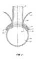
- FIG. 1is an elevational view, partially in phantom and in section, of a small vessel stent of the invention, with a graft vessel, partially in section and broken away, connected thereto, positioned in a target vessel.
- FIG. 2is a transverse cross-sectional view of the small vessel stent, together with the graft and target vessel, shown in FIG. 1 , taken along lines 2 — 2 .
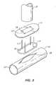
- FIG. 3is an exploded view of the graft vessel, the small vessel stent with the inner and outer flanges, and the graft vessel disconnected.
- FIG. 4is an elevational view, partially in phantom, of the small vessel stent shown in FIG. 3 , with the outer flange and the graft vessel, partially broken away, connected thereto, and with the inner flange in the target vessel lumen.
- FIG. 5is an elevational view of the small vessel stent shown in FIG. 4 ,. connected to the target vessel.
- FIG. 6is an elevational view of a prong and a prong receiving opening, on the outer flange which embodies features of the invention.
- FIG. 7is an elevational view, partially in section, of a small vessel stent with the inner flange folded for insertion into the target vessel, with the short dimension sides folded inward, and with the graft vessel, partially broken away.
- FIG. 8is an elevational view, partially in section, of a small vessel stent with the inner flange folded for insertion into the target vessel, with the short dimension sides and the long dimension sides folded inward, and with the graft vessel, partially broken away.
- FIG. 9is an elevational view of an compressible small vessel stent inner flange in a partially compressed configuration.
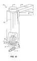
- FIG. 10is an elevational view, partially in section, of a small vessel stent applicator which embodies features of the invention.
- FIG. 11is a longitudinal cross sectional view of the applicator shown in FIG. 10 with a small vessel stent therein, in position in a target vessel.
- FIG. 12is an elevational, exploded view of a graft vessel, a large vessel anastomotic stent of the invention with the deformable sections in the first configuration, and a target vessel.
- FIG. 13is a transverse cross sectional view of the large vessel stent shown in FIG. 12 , taken along lines 13 — 13 .
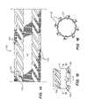
- FIG. 14is an flattened view of a large vessel anastomotic stent of the invention with the deformable sections in the first configuration.
- FIG. 15is an elevational view of a large vessel anastomotic stent of the invention with the distal deformable section in the second configuration.
- FIG. 16is a transverse cross sectional view of the large vessel stent shown in FIG. 15 , taken along lines 16 — 16 .
- FIG. 17is an elevational view, partially in section and broken away, of the large vessel stent shown in FIG. 12 , with an everted graft vessel thereon, and a target vessel.
- FIG. 18is a longitudinal cross-sectional view of the large vessel stent and graft vessel thereon in a target vessel.
- FIG. 19is a longitudinal cross-sectional view of the large vessel stent shown in FIG. 18 , with the distal end deformable section in the second configuration.
- FIG. 20is a longitudinal cross-sectional view of the large vessel stent shown in FIG. 19 , with the proximal end deformable section in the second configuration.
- FIG. 21is a flattened view of an alternative embodiment of the large vessel anastomotic stent of the invention having voids in the body.
- FIG. 22is a flattened view of an alternative embodiment of the large vessel anastomotic stent of the invention having a curvilinear distal end.
- FIG. 23is an elevational view of a large vessel stent applicator which embodies features of the invention.
- FIG. 24is a transverse cross sectional view, partially in section and broken away of the distal end of an applicator with a large vessel stent and graft vessel thereon, with a vessel penetrating member therein.
- FIGS. 25 and 26are transverse cross sectional views of the applicator assembly shown in FIG. 24 taken along lines 25 — 25 and 26 — 26 , respectively.
- FIG. 27is an elevational view of the distal end of the applicator shown in FIG. 23 .
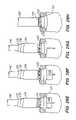
- FIGS. 28A–28Hare elevational views, partially in section, of the applicator, and large vessel stent and vessel penetrating member therein during connection of the large vessel stent to a target vessel.
- FIG. 29is an transverse cross sectional view of an alternative embodiment of the large vessel stent having a distal flange angled toward the distal end of the stent.
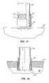
- FIG. 30is an elevational view of a human heart having a graft vessel attached thereto.
- FIG. 1A presently preferred embodiment of the small vessel stent 10 of the invention, for connecting one end of a graft vessel to a small target vessel, is illustrated in FIG. 1 .
- the small vessel stent 10comprises an outer flange 11 having a body 12 which defines an opening 13 configured to receive the end of the graft vessel 21 , and an inner flange 14 having a body 15 which defines an opening 16 .
- the inner flangeis configured to be connected to the outer flange, with the openings 13 , 16 at least in part aligned.
- prongs 17 on the inner flangeare configured to be received within small openings 18 in the outer flange, to thereby connect the flanges together.
- FIG. 1A presently preferred embodiment of the small vessel stent 10 of the invention, for connecting one end of a graft vessel to a small target vessel.
- the inner flange 14is configured to be positioned within a. lumen 23 of the target vessel 22 against an inner surface 24 of the target vessel
- the outer flange 11is configured to be positioned against an outer surface 25 of the target vessel 22 .
- the inner and outer flangeshave an arced configuration to facilitate positioning against the arced surface of the tubular vessel.
- the small vessel stent 10is preferably used with small target vessels, such as arteries, which typically have thin walls and small inner diameters.
- the inner and outer flangeshave a short dimension and a long dimension, i.e. are substantially oblong.
- the graft receiving opening 13 in the outer flange, and the opening 16 in the inner flange,are also substantially oblong.
- FIG. 3is an exploded view of the inner flange 14 , outer flange 1 1 , and a graft vessel 21 , at an incision 26 in the target vessel 22 .
- the graft vesselhas been connected to the outer flange by inserting the end of the graft vessel through the graft receiving opening 13 , and everting the graft end over the outer flange.
- connecting memberssuch as sutures, hooks or clips may be used to fix the graft vessel to the outer tubular member (not shown).
- the prongs 17 on the inner flangepierce through the wall of the graft vessel and then through the small openings 18 in the outer flange.
- FIG. 4illustrates the inner and outer flanges loosely connected together for positioning at the target vessel, with only a partial length of the prongs 17 inserted through the prong receiving opening 18 , before the flanges are tightened down around the wall of the target vessel.
- FIG. 5is an elevational view of the small vessel stent shown in FIG. 4 , connected to the target vessel, with a length of the free ends of the prongs 17 removed.
- the prongs 17 on the inner flange and the prong receiving openings 18 on the outer flangeare configured to fixedly mate together.
- FIG. 6illustrates one embodiment of the prong 17 and prong receiving openings 18 .
- the opening 18has deflectable tabs 19 which deflect to allow displacement of the prong 17 longitudinally into the opening from the under side of the outer flange to the upper side of the outer flange, but which wedge against the prong to prevent the inserted prong from moving out of the opening 18 from the upper side to the under side of the outer flange.
- a quick releasemay be provided on the prongs to allow the prongs which are only partially inserted through the prong receiving opening to be quickly released therefrom in the event of an aborted procedure.
- the inner flangehas a folded configuration having a reduced profile to facilitate insertion into the incision in the target vessel.
- the length of the stentis shortened by flexing the short dimensioned sides of the stent together, as illustrated in FIG. 7 .
- a pair of inwardly tensioned arms 43are used in one embodiment of the invention.
- the width of the: stentcan be shortened by flexing the long dimensioned sides of the stent together, as illustrated in FIG. 8 .
- the inner flangeis formed from a superelastic or pseudoelastic material, such as a NiTi alloy, to facilitate folding the inner flange and to provide improved sealing against the wall of the target vessel after the inner flange is unfolded inside the target vessel lumen.
- a superelastic or pseudoelastic materialsuch as a NiTi alloy
- FIG. 9illustrates an inner flange having a collapsible section 27 on the long dimensioned sides of the inner flange, comprising a series of short turns in alternating directions.
- the collapsible section 27is shown in a partially collapsed configuration in which the length of the inner flange is shortened by collapsing the long dimensioned sides of the inner flange.
- the inner flange having a collapsible section 27is formed of stainless steel.
- FIG. 10illustrates an applicator 31 used to position the inner flange 14 within the target vessel lumen 23 , and tighten the inner and outer flanges together around the wall of the target vessel.
- the applicator 31generally comprises a shaft 32 with proximal and distal ends, a handle 33 on the proximal end, and a connecting member 34 on the distal end for releasably attaching to the small vessel stent.
- the connecting member 34comprises an inner compressible member 35 which is slidably insertable into an outer housing member 36 .
- the compressible member 35has slots 37 configured to receive the prongs 17 on the inner flange 14 , and an opening 38 configured to receive the graft vessel.
- the free end of the graft vessel, unconnected to the small vessel stent 10 ,is outside of the applicator via the opening 38 .
- the housing member 36has an inner chamber 39 configured to receive the compressible member 35 .
- the chamber 39is smaller than at least a section of the compressible member 35 , to thereby compress the compressible member 35 to a smaller dimension when it is positioned within the chamber 39 .
- the small vessel stentis releasably connected to the applicator, after the inner and outer flange together with a graft vessel are connected together, by inserting the prongs 17 on the inner flange into the slots 37 .
- the compressible member 35clamps onto the prongs 17 as the compressible member 35 is positioned within the chamber 39 and the slots 37 are thereby compressed. In the embodiment illustrated in FIG. 10 , the compressible member 35 is partially out of the housing. Additionally, a connecting member (not shown) such as a clasp, clamp, or hook on the distal end of the applicator may be used to connect the outer flange to the applicator.
- FIG. 10illustrates, in an exploded view, the positioning of the inner flange 14 for releasably connecting to the applicator.
- the inner flange 14is typically connected to the outer flange with a graft vessel attached thereto before being connected to the applicator.
- FIG. 11is a longitudinal cross sectional view of an applicator as shown in FIG. 10 , with a small vessel stent therein, in position at a target vessel.
- the applicator 31may be provided with a insertion member for holding the inner flange in the folded configuration facilitating introduction into the target vessel lumen through the incision in the target vessel.
- the applicator insertion membercomprises a pair of inwardly tensioned arms 43 extending past the distal end of the shaft for releasably holding the inner flange in the folded configuration, as illustrated in FIGS. 7 and 8 .
- the small vessel stentconnects one end of a graft vessel to a target vessel to form an anastomosis.
- the target vesselis incised, and balloons on occlusion catheters positioned against the target vessel are inflated to occlude blood flow upstream and downstream of the anastomosis site.
- the outer flangeis attached to one end of a graft vessel as described above, and, in the embodiment illustrated in FIG. 1 , the prongs on the inner flange are inserted through the graft vessel and into the prong receiving openings in the outer flange.
- the graft vesselmay be occluded with a temporary clamp on the mid portion of the graft, to prevent blood loss through the graft vessel during the procedure.
- the inner flangeis inserted into the target vessel lumen, and the inner and outer flanges are tightened together to compress the graft vessel against the outer surface of the target vessel. After the inner and outer flanges are tightened together, the free end of each prong is broken off to decrease the lent of the prongs left inside the patient.
- the prongsare typically provided with a weakened point 42 near the body of the inner flange to facilitate breaking of the prong by tensile forces or by fatigue failure due to strain hardening.
- the occlusion balloonsare deflated and the occlusion catheters removed, with the stent connected to the target vessel and the graft vessel in fluid communication with the target vessel lumen.
- the outer flangeis longer and wider than the inner flange.
- the outer flangehas a length of about 4 mm to about 12 mm, preferably about 7 mm to about 9 mm, and a width of about 1 mm to about 5 mm.
- the wall thickness of the body of the outer flangeis about 0.10 mm to about 0.30 mm.
- the inner flangehas a length of about 4 mm to about 12 mm, preferably about 7 mm to about 9 mm, and a width of about 0.5 mm to about 5 mm, and preferably about 2 mm to about 4 mm.
- the wall thickness of the body of the inner flangeis about 0.10 mm to about 0.25 mm.
- the inner and outer flangesare preferably formed of stainless steel, preferably 316 stainless steel, although, as previously discussed herein, superelastic or pseudoelastic materials such as nickel titanium alloys, titanium, or tantalum, may also be used. Additionally, advanced polymers which can be plastically deformed, such as polyetheretherketone, may be used.
- FIG. 12illustrates a presently preferred embodiment of the large vessel stent 110 of the invention, for connecting one end of a graft vessel 125 to a large target vessel 127 .
- the large vessel stent 110comprises a substantially cylindrical body 111 having an open proximal end 112 , open distal end 113 , a lumen 114 extending therein configured to receive the end of the graft vessel 125 .
- FIG. 13illustrates a transverse cross section of the large vessel stent 110 shown in FIG. 12 , taken along lines 13 — 13 .
- FIG. 14illustrates a flattened view of the large vessel stent 110 shown in FIG. 12 .
- the cylindrical bodyhas a distal deformable section 115 and a proximal deformable section 116 .
- the deformable sections 115 , 116have a first configuration for insertion into the target vessel, and a radially expanded second configuration for connecting to the target vessel.
- the distal and proximal deformable sections 115 , 116comprises a plurality of helical members 123 , 124 , respectively.
- each helical memberhas a proximal end radially spaced on the stent body relative to the helical member distal end.
- the helical membersare radially spaced around the circumference of the cylindrical body between longitudinally spaced portions of the cylindrical body.
- the helical members forming the deformable sectionsare shown in the first configuration prior to being radially expanded to the second configuration.
- the distal deformable section 115radially expands to the second configuration to form a distal end flange 121 , configured to apply a force radial to the cylindrical body 111 longitudinal axis against the target vessel and thereby connect the stent to the target vessel.
- the proximal deformable section 116radially expands to the second configuration to form a proximal end flange 122 , as illustrated in FIG. 20 .
- FIG. 16illustrates a transverse cross section of the large vessel stent 110 shown in FIG. 15 , taken along lines 16 — 16 .
- FIG. 17illustrates the large vessel stent shown in FIG. 12 with a graft vessel 125 attached thereto.
- the graft vesselis attached to the large-vessel anastomotic stent by inserting one end of the graft vessel into the proximal end of the cylindrical body and, in a preferred embodiment, everting the graft end 126 out the cylindrical body distal end.
- the graft vesselmay be everted over all or only a section of the outer surface of the large vessel stent 110 . In the embodiment illustrated in FIG. 17 , the graft is everted over the distal deformable section 115 which is in the first configuration prior to being radially expanded to the second configuration.
- FIGS. 18–20illustrate the large vessel stent shown in FIG. 17 within a wall of the target vessel 127 before and after deployment of the distal flange 121 and proximal flange 122 .
- the stenthas been inserted into an incision in a wall of the target vessel, with the distal end of the stent within the lumen 128 of the target vessel 127 and the proximal end 112 of the stent extending outside of the target vessel.
- the distal deformable section 115has been radially expanded to form the distal end flange 121 .
- the stent bodylongitudinally collapses, and the distal end flange is positioned at least in part within the wall of the target vessel, so that the flange applies a force radial to the stent longitudinal axis, illustrated by the arrow R, against the wall of the target vessel defining the incision therein. Additionally, an axial force, illustrated by the arrow A, is applied against the target vessel wall, compressing the target vessel wall.
- the final position of the distal end flangemay vary, with the distal end flange being completely within the target vessel wall as shown, or, alternatively, partially within the target vessel lumen (not shown). In FIG.
- the proximal deformable section 116has been radially expanded to form the proximal end flange 122 .
- the proximal end flange positioned against the outer wall of the target vesselproduces an axial force, illustrated by the arrow A, against the target vessel.
- the proximal end flangeis in contact with an outer surface of the target vessel wall.
- the proximal end flangemay be in contact with the media of the target vessel between the inner and outer surface of the target vessel wall, and preferably with the proximal end of the stent flush with the outer surface of the target vessel (not shown).
- the degree to which flange is deployedmay be varied to control how and where the flange contacts the target vessel wall.
- the proximal deformable sectioncan be radially expanded and longitudinally collapsed to a greater or lesser degree, so that the proximal end flange is in contact with the target vessel either on an outer surface of the target vessel or within the incision therein in contact with the media of the target vessel wall.
- the large vessel stent 110is shown in FIG. 12 with a proximal deformable section and a distal deformable section, forming proximal and distal flanges, respectively, the large vessel stent may have one or more deformable sections.
- an intermediate deformable section(not shown) between the proximal and distal end deformable sections may be provided for additional sealing and securing force against the media of the target vessel wall.
- FIG. 21illustrates an alternative embodiment in which voids or openings 129 are provided in the body wall which allow for tissue ingrowth, to thus facilitate sealing and securing of the anastomosis.
- a peripheral edge on the distal end of the large vessel stentis curvilinear, so that deployment of the distal end flange increases the diameter of the open distal end.
- the generally sinusodial edgeincreases the diameter of the opening in the distal end as the distal deformable section 115 is longitudinally collapsed.
- an applicator 131is typically used to deploy the flanges and connect the large vessel stent 110 to the target vessel 127 , as illustrated in FIG. 23 .
- the applicator 131comprises an elongated stent delivery member comprising a shaft 133 having an outer tubular member 134 having a lumen 135 therein, an inner tubular member 136 having a lumen 137 configured to receive the graft vessel 125 and being rotatably located within the lumen of the outer tubular member, a handle 138 on the proximal end of the shaft, and connecting members 141 on the distal end of the inner and outer tubular members which releasably secure the large vessel stent 110 to the applicator 131 .
- FIG. 23illustrates an enlarged view of the distal end of an applicator as shown in FIG. 23 , with a large vessel stent 110 and graft vessel 125 thereon.
- FIGS. 26 and 27illustrate transverse cross sections of the applicator shown in FIG. 24 , taken along lines 26 — 26 and 27 — 27 , respectively.
- FIG. 27illustrates an enlarged view of the distal end of the applicator 131 shown in. FIG. 23 .
- the connecting members 141 on the outer tubular member 134comprise tabs 142 configured to mate with slits 143 , as illustrated in FIG. 12 , on the proximal end of the stent.
- the connecting members 141 on the inner tubular member 136comprise angular slits 144 which Slidably receive tabs 145 , as illustrated in FIG. 13 on the distal end of the stent.
- connection memberscan be used including releasable clamps, clips, hooks, and the like.
- the applicator 131includes a vessel penetrating member 146 , as illustrated in FIGS. 24 and 28 , for forming an incision in the target vessel.
- the applicatormay be provided with one or more inflatable members for enlarging the incision, and/or drawing the applicator and stent into the incision.
- a vessel penetrating member 146having proximal and distal ends, a piercing member 147 on the distal end, and at least one inflatable member on a distal section of member 146 , is configured to be received in the inner lumen of the inner tubular member, 136 .
- FIG. 28a vessel penetrating member 146 having proximal and distal ends, a piercing member 147 on the distal end, and at least one inflatable member on a distal section of member 146 , is configured to be received in the inner lumen of the inner tubular member, 136 .
- a proximal balloon 148which is preferably formed from noncompliant material, is provided on the outer tubular member for expanding the incision in the target vessel
- a distal balloon 151which is preferably formed from compliant material, is provided distal to the noncompliant balloon 148 , for drawing the vessel penetrating member 146 into the target vessel lumen 128 .
- the distal balloonmay be omitted and the catheter advanced through the incision and into the target vessel lumen physically or by other suitable methods, as when the proximal balloon is shaped to advance into the target vessel lumen during inflation.
- the target vesselmay be held to resist the force of inserting the stent into the aortal wall, as by a suction applicator (not shown) positioned against an outer surface of the target vessel, which pulls the target vessel toward the applicator.
- the large vessel stentwith a graft vessel connected thereto, is introduced into the patient, inserted into the target vessel and connected thereto by deployment of the flange.
- FIGS. 28A–28Hillustrate the connection of the large vessel stent to a target vessel.
- the stent 110with an everted graft vessel 125 thereon, is releasably secured to the distal end of the, applicator.
- the graft vesselis within the lumen of the inner tubular member, and the vessel penetrating member 146 is within the lumen of the graft vessel 125 .
- the applicator 131 and stent 110 assemblyis introduced into the patient and positioned adjacent the target vessel 127 .
- An incision in the target vessel wallis formed by inserting the piercing member 147 into the target vessel, and the incision is enlarged by inflating the proximal balloon 148 on the vessel penetrating member 146 , see FIGS. 28B and 28C .
- the distal end of the applicatoris then displaced distally into the target vessel lumen 128 by inflating the distal balloon 151 , see FIG. 28D .
- the applicator inner tubular memberis rotated relative to the-applicator outer tubular member, so that the distal end of the stent rotates relative to the proximal end of the stent, and the distal end flange is deployed, see FIG.
- the distal end of the stentis positioned within the target vessel lumen before the distal end flange 121 is deployed, to facilitate deployment thereof.
- the distal deformable sectionis positioned at least in part within the target vessel lumen before the distal flange is deployed.
- the proximal end flange 122is deployed by further rotating the applicator tubular members as outlined above for the distal end flange, see FIG. 28F .
- the balloons 148 , 151 on the vessel penetrating member 146are then deflated and the applicator 131 removed from the target vessel 127 , leaving the graft vessel 125 connected thereto, see, FIGS. 28G and 28H .
- the distal end flangeis configured to deploy at lower torque than the proximal end flange.
- a deflecting section 153is provided on the helical members 123 , 124 , which bends during the deployment of the flanges.
- the deflecting section 153is formed by at least one notch in each helical member, having a depth which decreases the transverse dimension of the helical members at the notch.
- the a deflecting sectionis formed by-two opposed notches 154 on opposite sides of the helical members.
- the notches on the distal helical membershave a depth that is greater than the depth of the notches on the proximal helical members. Consequently, the transverse dimension of the deflecting section on the distal helical member is smaller than that of the proximal helical members, so that the distal flange will deploy before the proximal flange.
- the distal section helical membersradially expand at lower torque than the proximal helical members, so that rotating the proximal and distal ends of the stent body relative to one another causes the distal end flange to deploy first, followed by the proximal end flange.
- the helical membershave deflecting sections 153 on the proximal and distal-ends, and an intermediate deflecting section located substantially centrally along the length of the helical member between the proximal and distal ends of the helical member.
- the intermediate deflecting sectionIn the deployed flange, the intermediate deflecting section is thus located on a peripheral extremity of the deployed flange and the flange is substantially perpendicular to the stent longitudinal axis.
- the intermediate deflecting sectionmay be located distally or proximally along the length of the helical member, so that the flange is angled relative to the longitudinal axis of the stent.
- the flangeis angled toward the distal end of the large vessel stent 110 , as illustrated in FIG. 29 .
- the length of the large vessel stent before deployment of the flangesis greater than the width of the target vessel wall, so that the deformable sections are on either side of the target vessel, at least in part outside of the incision in the target vessel wall.
- the length of the stent after the flanges are deployed, as illustrated in FIG. 20is substantially equal to the width of the target vessel wall.
- the length of the stent 110is about 0.5 mm to about 5 mm, and the diameter is about 4 mm to about 10 mm.
- the large vessel stentis preferably formed from stainless steel. However, other suitable materials may be used, including tantalum, titanium, and alloys thereof.
- the large vessel stent wall thicknessis about 0.10 mm to about 0.20 mm.
- the anastomotic stents of the inventionmay be used for a variety of anastomosis procedures, including coronary bypass surgery.
- the distal end of a dissected mammary arterycan be connected to a coronary artery, using a small vessel stent of the invention.
- one or more slicesare made in the end of the mammary artery in order to increase to diameter of the mammary artery to facilitate its connection to the outer flange of the small vessel stent.
- FIG. 30illustrates a heart 160 on which a coronary bypass has been performed using the anastomotic stents of the invention.
- the distal end of a harvested vein graft 125is connected to the coronary artery 161 using a small vessel stent of the invention, and the proximal end of the graft vessel is connected to the descending aorta 162 using a large vessel stent of the invention.
- the large vessel stentIn an anastomotic system using the large vessel stent in combination with the small vessel stent, the large vessel stent would preferably be connected to the target vessel first, so that the lumen of the graft vessel would be accessible through the other end of the graft vessel, to thereby provide access for a catheter which incises and expands the aortal wall.
- the small vessel stentwould be connected next, because it requires no access through the lumen of the graft vessel.
- anastomotic stents of the inventionmay be used in a number of anastomosis procedures.
- the other types of anastomosis proceduresinclude, femoral-femoral bypass, vascular shunts, subclavian-carotid bypass, organ transplants, and the like.
Landscapes
- Health & Medical Sciences (AREA)
- Life Sciences & Earth Sciences (AREA)
- General Health & Medical Sciences (AREA)
- Public Health (AREA)
- Engineering & Computer Science (AREA)
- Biomedical Technology (AREA)
- Heart & Thoracic Surgery (AREA)
- Surgery (AREA)
- Veterinary Medicine (AREA)
- Animal Behavior & Ethology (AREA)
- Medical Informatics (AREA)
- Nuclear Medicine, Radiotherapy & Molecular Imaging (AREA)
- Molecular Biology (AREA)
- Gastroenterology & Hepatology (AREA)
- Pulmonology (AREA)
- Cardiology (AREA)
- Oral & Maxillofacial Surgery (AREA)
- Transplantation (AREA)
- Vascular Medicine (AREA)
- Prostheses (AREA)
- Surgical Instruments (AREA)
Abstract
Description
Claims (12)
Priority Applications (2)
| Application Number | Priority Date | Filing Date | Title |
|---|---|---|---|
| US09/924,556US7041110B2 (en) | 1998-08-12 | 2001-08-09 | Method and system for attaching a graft to a blood vessel |
| US11/372,839US20060155313A1 (en) | 1998-08-12 | 2006-03-10 | Integrated anastomosis tool and method |
Applications Claiming Priority (2)
| Application Number | Priority Date | Filing Date | Title |
|---|---|---|---|
| US09/132,711US6461320B1 (en) | 1998-08-12 | 1998-08-12 | Method and system for attaching a graft to a blood vessel |
| US09/924,556US7041110B2 (en) | 1998-08-12 | 2001-08-09 | Method and system for attaching a graft to a blood vessel |
Related Parent Applications (1)
| Application Number | Title | Priority Date | Filing Date |
|---|---|---|---|
| US09/132,711ContinuationUS6461320B1 (en) | 1998-08-12 | 1998-08-12 | Method and system for attaching a graft to a blood vessel |
Related Child Applications (1)
| Application Number | Title | Priority Date | Filing Date |
|---|---|---|---|
| US11/372,839DivisionUS20060155313A1 (en) | 1998-08-12 | 2006-03-10 | Integrated anastomosis tool and method |
Publications (2)
| Publication Number | Publication Date |
|---|---|
| US20020026137A1 US20020026137A1 (en) | 2002-02-28 |
| US7041110B2true US7041110B2 (en) | 2006-05-09 |
Family
ID=22455260
Family Applications (5)
| Application Number | Title | Priority Date | Filing Date |
|---|---|---|---|
| US09/132,711Expired - LifetimeUS6461320B1 (en) | 1998-08-12 | 1998-08-12 | Method and system for attaching a graft to a blood vessel |
| US09/886,074Expired - LifetimeUS7004949B2 (en) | 1998-08-12 | 2001-06-18 | Method and system for attaching a graft to a blood vessel |
| US09/924,556Expired - LifetimeUS7041110B2 (en) | 1998-08-12 | 2001-08-09 | Method and system for attaching a graft to a blood vessel |
| US10/412,173AbandonedUS20040015180A1 (en) | 1998-08-12 | 2003-04-11 | Method and system for attaching a graft to a blood vessel |
| US11/372,839AbandonedUS20060155313A1 (en) | 1998-08-12 | 2006-03-10 | Integrated anastomosis tool and method |
Family Applications Before (2)
| Application Number | Title | Priority Date | Filing Date |
|---|---|---|---|
| US09/132,711Expired - LifetimeUS6461320B1 (en) | 1998-08-12 | 1998-08-12 | Method and system for attaching a graft to a blood vessel |
| US09/886,074Expired - LifetimeUS7004949B2 (en) | 1998-08-12 | 2001-06-18 | Method and system for attaching a graft to a blood vessel |
Family Applications After (2)
| Application Number | Title | Priority Date | Filing Date |
|---|---|---|---|
| US10/412,173AbandonedUS20040015180A1 (en) | 1998-08-12 | 2003-04-11 | Method and system for attaching a graft to a blood vessel |
| US11/372,839AbandonedUS20060155313A1 (en) | 1998-08-12 | 2006-03-10 | Integrated anastomosis tool and method |
Country Status (9)
| Country | Link |
|---|---|
| US (5) | US6461320B1 (en) |
| EP (2) | EP1149567A3 (en) |
| JP (1) | JP2002522154A (en) |
| AT (1) | ATE347332T1 (en) |
| AU (1) | AU5543899A (en) |
| CA (1) | CA2339191A1 (en) |
| DE (1) | DE69934319T2 (en) |
| ES (1) | ES2277445T3 (en) |
| WO (1) | WO2000009040A1 (en) |
Cited By (23)
| Publication number | Priority date | Publication date | Assignee | Title |
|---|---|---|---|---|
| US20030088256A1 (en)* | 2001-10-03 | 2003-05-08 | Conston Stanley R. | Devices and methods for interconnecting vessels |
| US20030100920A1 (en)* | 1999-07-28 | 2003-05-29 | Akin Jodi J. | Devices and methods for interconnecting conduits and closing openings in tissue |
| US20040097988A1 (en)* | 1999-01-15 | 2004-05-20 | Ventrica, Inc. | Methods and devices for placing a conduit in fluid communication with a target vessel |
| US20040168691A1 (en)* | 1998-02-13 | 2004-09-02 | Sharkawy A. Adam | Conduits for use in placing a target vessel in fluid communication with source of blood |
| US20050043781A1 (en)* | 1998-02-13 | 2005-02-24 | Mark Foley | Methods and devices providing transmyocardial blood flow to the arterial vascular system of the heart |
| US20050165426A1 (en)* | 2002-06-19 | 2005-07-28 | Scott Manzo | Method and apparatus for anastomosis including annular joining member |
| US20060111731A1 (en)* | 1996-07-23 | 2006-05-25 | Tyco Healthcare Group Lp | Anastomosis instrument and method for performing same |
| US20070055344A1 (en)* | 1998-02-13 | 2007-03-08 | Gittings Darin C | Devices and methods for use in performing transmyocardial coronary bypass |
| US20070290497A1 (en)* | 2006-06-15 | 2007-12-20 | Arendt Albert L | Children's ride-on vehicles with reconfigured bodies and methods for forming the same |
| US20080018016A1 (en)* | 1999-09-10 | 2008-01-24 | Rapacki Alan R | Manufacturing conduits for use in placing a target vessel in fluid communication with a source of blood |
| US7351247B2 (en) | 2002-09-04 | 2008-04-01 | Bioconnect Systems, Inc. | Devices and methods for interconnecting body conduits |
| US20080171101A1 (en)* | 1999-09-10 | 2008-07-17 | Rapacki Alan R | Manufacturing conduits for use in placing a target vessel in fluid communication with a source of blood |
| US20090036817A1 (en)* | 2007-08-02 | 2009-02-05 | Bio Connect Systems | Implantable flow connector |
| US20090143759A1 (en)* | 2007-11-30 | 2009-06-04 | Jacques Van Dam | Methods, Devices, Kits and Systems for Defunctionalizing the Cystic Duct |
| US20110054381A1 (en)* | 2009-05-29 | 2011-03-03 | Jacques Van Dam | Biliary shunts, delivery systems, and methods of using the same |
| US7993356B2 (en) | 1998-02-13 | 2011-08-09 | Medtronic, Inc. | Delivering a conduit into a heart wall to place a coronary vessel in communication with a heart chamber and removing tissue from the vessel or heart wall to facilitate such communication |
| US8162963B2 (en)* | 2004-06-17 | 2012-04-24 | Maquet Cardiovascular Llc | Angled anastomosis device, tools and method of using |
| US9282967B2 (en) | 2007-08-02 | 2016-03-15 | Bioconnect Systems, Inc. | Implantable flow connector |
| US9314600B2 (en) | 2012-04-15 | 2016-04-19 | Bioconnect Systems, Inc. | Delivery system for implantable flow connector |
| US9364238B2 (en) | 2013-04-16 | 2016-06-14 | Ethicon Endo-Surgery, Inc. | Method and apparatus for joining hollow organ sections in anastomosis |
| US10434293B2 (en) | 2012-04-15 | 2019-10-08 | Tva Medical, Inc. | Implantable flow connector |
| US10631865B2 (en) | 2017-01-30 | 2020-04-28 | Ethicon Llc | Tissue compression device with features to contain needles and suture during packaging and placement in body |
| US11033272B2 (en) | 2013-04-16 | 2021-06-15 | Ethicon Endo-Surgery, Inc. | Methods for partial diversion of the intestinal tract |
Families Citing this family (93)
| Publication number | Priority date | Publication date | Assignee | Title |
|---|---|---|---|---|
| US5732872A (en) | 1994-06-17 | 1998-03-31 | Heartport, Inc. | Surgical stapling instrument |
| US5904697A (en) | 1995-02-24 | 1999-05-18 | Heartport, Inc. | Devices and methods for performing a vascular anastomosis |
| US5976159A (en) | 1995-02-24 | 1999-11-02 | Heartport, Inc. | Surgical clips and methods for tissue approximation |
| US20020019642A1 (en) | 1996-07-23 | 2002-02-14 | Keith Milliman | Anastomosis instrument and method for performing same |
| US7223273B2 (en)* | 1996-07-23 | 2007-05-29 | Tyco Healthcare Group Lp | Anastomosis instrument and method for performing same |
| JP2001503657A (en) | 1996-11-08 | 2001-03-21 | ハウザー,ラッセル,エイ. | Transcutaneous bypass graft and fixation system |
| US6063114A (en)* | 1997-09-04 | 2000-05-16 | Kensey Nash Corporation | Connector system for vessels, ducts, lumens or hollow organs and methods of use |
| US6193734B1 (en) | 1998-01-23 | 2001-02-27 | Heartport, Inc. | System for performing vascular anastomoses |
| US6352543B1 (en) | 2000-04-29 | 2002-03-05 | Ventrica, Inc. | Methods for forming anastomoses using magnetic force |
| US6176864B1 (en)* | 1998-03-09 | 2001-01-23 | Corvascular, Inc. | Anastomosis device and method |
| US6979338B1 (en) | 1998-05-29 | 2005-12-27 | By-Pass Inc. | Low profile anastomosis connector |
| US7063711B1 (en) | 1998-05-29 | 2006-06-20 | By-Pass, Inc. | Vascular surgery |
| KR20010052459A (en) | 1998-05-29 | 2001-06-25 | 바이-패스, 인크. | Methods and devices for vascular surgery |
| US6641593B1 (en) | 1998-06-03 | 2003-11-04 | Coalescent Surgical, Inc. | Tissue connector apparatus and methods |
| US6945980B2 (en) | 1998-06-03 | 2005-09-20 | Medtronic, Inc. | Multiple loop tissue connector apparatus and methods |
| US6607541B1 (en) | 1998-06-03 | 2003-08-19 | Coalescent Surgical, Inc. | Tissue connector apparatus and methods |
| US6613059B2 (en) | 1999-03-01 | 2003-09-02 | Coalescent Surgical, Inc. | Tissue connector apparatus and methods |
| US6599302B2 (en) | 1998-06-10 | 2003-07-29 | Converge Medical, Inc. | Aortic aneurysm treatment systems |
| US6206913B1 (en) | 1998-08-12 | 2001-03-27 | Vascular Innovations, Inc. | Method and system for attaching a graft to a blood vessel |
| US6461320B1 (en) | 1998-08-12 | 2002-10-08 | Cardica, Inc. | Method and system for attaching a graft to a blood vessel |
| US8118822B2 (en) | 1999-03-01 | 2012-02-21 | Medtronic, Inc. | Bridge clip tissue connector apparatus and methods |
| US6695859B1 (en) | 1999-04-05 | 2004-02-24 | Coalescent Surgical, Inc. | Apparatus and methods for anastomosis |
| AU5143000A (en)* | 1999-05-18 | 2000-12-05 | Vascular Innovations, Inc. | Implantable medical device such as an anastomosis device |
| US6673088B1 (en) | 1999-05-18 | 2004-01-06 | Cardica, Inc. | Tissue punch |
| US6428550B1 (en)* | 1999-05-18 | 2002-08-06 | Cardica, Inc. | Sutureless closure and deployment system for connecting blood vessels |
| US7048751B2 (en) | 2001-12-06 | 2006-05-23 | Cardica, Inc. | Implantable medical device such as an anastomosis device |
| AU5150600A (en) | 1999-05-18 | 2000-12-05 | Vascular Innovations, Inc. | Tissue punch |
| US8529583B1 (en) | 1999-09-03 | 2013-09-10 | Medtronic, Inc. | Surgical clip removal apparatus |
| US6926730B1 (en) | 2000-10-10 | 2005-08-09 | Medtronic, Inc. | Minimally invasive valve repair procedure and apparatus |
| US6551332B1 (en) | 2000-03-31 | 2003-04-22 | Coalescent Surgical, Inc. | Multiple bias surgical fastener |
| US7232449B2 (en) | 2000-04-29 | 2007-06-19 | Medtronic, Inc. | Components, systems and methods for forming anastomoses using magnetism or other coupling means |
| US6802847B1 (en) | 2000-04-29 | 2004-10-12 | Ventrica, Inc. | Devices and methods for forming magnetic anastomoses and ports in vessels |
| US6596003B1 (en) | 2000-06-28 | 2003-07-22 | Genzyme Corporation | Vascular anastomosis device |
| US6776785B1 (en) | 2000-10-12 | 2004-08-17 | Cardica, Inc. | Implantable superelastic anastomosis device |
| US6890338B1 (en)* | 2001-02-27 | 2005-05-10 | Origin Medsystems, Inc. | Method and apparatus for performing anastomosis using ring having tines with weak sections |
| US7122040B2 (en) | 2001-06-15 | 2006-10-17 | J. Donald Hill | Suture placement apparatus |
| US6858035B2 (en) | 2001-07-05 | 2005-02-22 | Converge Medical, Inc. | Distal anastomosis system |
| US6972023B2 (en) | 2001-07-05 | 2005-12-06 | Converge Medical, Inc. | Distal anastomosis system |
| US7029482B1 (en) | 2002-01-22 | 2006-04-18 | Cardica, Inc. | Integrated anastomosis system |
| US7335216B2 (en) | 2002-01-22 | 2008-02-26 | Cardica, Inc. | Tool for creating an opening in tissue |
| US8012164B1 (en) | 2002-01-22 | 2011-09-06 | Cardica, Inc. | Method and apparatus for creating an opening in the wall of a tubular vessel |
| US7223274B2 (en) | 2002-01-23 | 2007-05-29 | Cardica, Inc. | Method of performing anastomosis |
| US7195142B2 (en) | 2003-05-30 | 2007-03-27 | Tyco Healthcare Group Lp | End-to-end anastomosis instrument and method for performing same |
| US7258694B1 (en) | 2002-06-17 | 2007-08-21 | Origin Medsystems, Inc. | Medical punch and surgical procedure |
| NO20023605D0 (en) | 2002-07-29 | 2002-07-29 | Sumit Roy | Method and apparatus for interconnecting two tubular members |
| US6896688B2 (en)* | 2002-09-12 | 2005-05-24 | Edrich Health Technologies, Inc. | Prosthetic vascular graft connector |
| US8066724B2 (en) | 2002-09-12 | 2011-11-29 | Medtronic, Inc. | Anastomosis apparatus and methods |
| US8105345B2 (en) | 2002-10-04 | 2012-01-31 | Medtronic, Inc. | Anastomosis apparatus and methods |
| US7309361B2 (en)* | 2002-10-23 | 2007-12-18 | Wasielewski Ray C | Biologic modular tibial and femoral component augments for use with total knee arthroplasty |
| FR2847151B1 (en)* | 2002-11-15 | 2005-01-21 | Claude Mialhe | OCCLUSIVE DEVICE WITH MEDICAL OR SURGICAL DESTINATION |
| FR2847150B1 (en)* | 2002-11-15 | 2005-01-21 | Claude Mialhe | OCCLUSIVE DEVICE WITH MEDICAL OR SURGICAL DESTINATION |
| US7182769B2 (en) | 2003-07-25 | 2007-02-27 | Medtronic, Inc. | Sealing clip, delivery systems, and methods |
| US8721710B2 (en)* | 2003-08-11 | 2014-05-13 | Hdh Medical Ltd. | Anastomosis system and method |
| US20050043749A1 (en)* | 2003-08-22 | 2005-02-24 | Coalescent Surgical, Inc. | Eversion apparatus and methods |
| US8394114B2 (en) | 2003-09-26 | 2013-03-12 | Medtronic, Inc. | Surgical connection apparatus and methods |
| US20050070935A1 (en)* | 2003-09-30 | 2005-03-31 | Ortiz Mark S. | Single lumen access deployable ring for intralumenal anastomosis |
| US7452363B2 (en)* | 2003-09-30 | 2008-11-18 | Ethicon Endo-Surgery, Inc. | Applier for fastener for single lumen access anastomosis |
| US8211142B2 (en) | 2003-09-30 | 2012-07-03 | Ortiz Mark S | Method for hybrid gastro-jejunostomy |
| US7879047B2 (en) | 2003-12-10 | 2011-02-01 | Medtronic, Inc. | Surgical connection apparatus and methods |
| US7585306B2 (en) | 2003-12-24 | 2009-09-08 | Maquet Cardiovascular Llc | Anastomosis device, tools and methods of using |
| US20050251180A1 (en)* | 2004-04-12 | 2005-11-10 | Vanderbilt University | Intravascular vessel anastomosis device |
| US8882787B2 (en)* | 2005-03-02 | 2014-11-11 | St. Jude Medical, Cardiology Division, Inc. | Tissue anchor apparatus |
| WO2006127985A2 (en) | 2005-05-26 | 2006-11-30 | Texas Heart Institute | Surgical system and method for attaching a prosthetic vessel to a hollow structure |
| WO2007004228A1 (en)* | 2005-07-06 | 2007-01-11 | Endogun Medical Systems Ltd. | Surgical fasteners and fastening devices |
| US20070010833A1 (en)* | 2005-07-07 | 2007-01-11 | Don Tanaka | Method for interconnecting hollow bodies |
| US20070073317A1 (en)* | 2005-07-07 | 2007-03-29 | Don Tanaka | System for interconnecting hollow bodies |
| US8029522B2 (en)* | 2005-08-05 | 2011-10-04 | Ethicon Endo-Surgery, Inc. | Method and apparatus for sealing a gastric opening |
| US8157833B2 (en)* | 2005-11-09 | 2012-04-17 | Applied Medical Resources Corporation | Trocars with advanced fixation |
| US8518100B2 (en)* | 2005-12-19 | 2013-08-27 | Advanced Cardiovascular Systems, Inc. | Drug eluting stent for the treatment of dialysis graft stenoses |
| US7625392B2 (en)* | 2006-02-03 | 2009-12-01 | James Coleman | Wound closure devices and methods |
| BRPI0602380A (en)* | 2006-06-06 | 2008-01-22 | Luiz Gonzaga Granja Jr | anastomosis prosthesis |
| WO2008115922A1 (en) | 2007-03-19 | 2008-09-25 | Michael Brenzel | Methods and apparatus for occlusion of body lumens |
| GB2450085B (en)* | 2007-06-08 | 2009-10-28 | Univ Hospitals Of Leicester Nh | Collapsible stent |
| US10004507B2 (en) | 2007-06-18 | 2018-06-26 | Asfora Ip, Llc | Vascular anastomosis device and method |
| US9504469B2 (en) | 2007-06-18 | 2016-11-29 | Asfora Ip, Llc | Vascular anastomosis device and method |
| US8361092B1 (en) | 2007-06-18 | 2013-01-29 | Wilson T. Asfora | Vascular anastomosis device and method |
| US9301761B2 (en) | 2007-10-22 | 2016-04-05 | James E. Coleman | Anastomosis devices and methods |
| US8177836B2 (en) | 2008-03-10 | 2012-05-15 | Medtronic, Inc. | Apparatus and methods for minimally invasive valve repair |
| UA107914C2 (en) | 2008-05-23 | 2015-03-10 | Е. І. Дю Пон Де Немур Енд Компані | Dgat genes from oil organisms to increase production of spare lipid profiles of seeds and modified fatty acids in oleaginous plants |
| US8197498B2 (en)* | 2008-11-06 | 2012-06-12 | Trinitas Ventures Ltd. | Gastric bypass devices and procedures |
| JP5329208B2 (en)* | 2008-12-25 | 2013-10-30 | ブリヂストンスポーツ株式会社 | Putter head |
| US8518060B2 (en) | 2009-04-09 | 2013-08-27 | Medtronic, Inc. | Medical clip with radial tines, system and method of using same |
| US8668704B2 (en) | 2009-04-24 | 2014-03-11 | Medtronic, Inc. | Medical clip with tines, system and method of using same |
| WO2011005812A2 (en)* | 2009-07-07 | 2011-01-13 | Marwan Tabbara | Surgical methods, devices, and kits |
| US20140155804A1 (en)* | 2009-07-07 | 2014-06-05 | Marwan Tabbara | Surgical devices and kits |
| DE102010010483B4 (en) | 2010-02-28 | 2017-02-09 | Björn H. Koslar | Medical implant |
| US9247930B2 (en) | 2011-12-21 | 2016-02-02 | James E. Coleman | Devices and methods for occluding or promoting fluid flow |
| US9848880B2 (en) | 2013-11-20 | 2017-12-26 | James E. Coleman | Adjustable heart valve implant |
| US9855048B2 (en) | 2013-11-20 | 2018-01-02 | James E. Coleman | Controlling a size of a pylorus |
| US9603600B2 (en)* | 2013-11-20 | 2017-03-28 | James E. Coleman | Actuator for deployable implant |
| PL3653177T3 (en) | 2015-01-11 | 2022-01-31 | Ascyrus Medical, Llc | Hybrid device for surgical aortic repair |
| US10888412B1 (en) | 2019-10-22 | 2021-01-12 | Bipore Medical Devices, Inc. | Stent-graft for anastomosis |
| US11712237B1 (en)* | 2022-07-20 | 2023-08-01 | Samothrace Medical Innovations, Inc. | Anatomical tissue anchor and related methods |
Citations (236)
| Publication number | Priority date | Publication date | Assignee | Title |
|---|---|---|---|---|
| US3254651A (en) | 1962-09-12 | 1966-06-07 | Babies Hospital | Surgical anastomosis methods and devices |
| US3254605A (en) | 1963-04-08 | 1966-06-07 | F N R D Ltd | Hydraulic pumps |
| US3519187A (en) | 1966-12-06 | 1970-07-07 | Nickolai Nickolajevich Kapitan | Instrument for suturing vessels |
| US3774615A (en) | 1971-02-08 | 1973-11-27 | Ceskoslovenska Akademie Ved | Device for connecting or joining the ends of interrupted tubular organs in surgical operations without stitching |
| US4118806A (en) | 1976-02-04 | 1978-10-10 | Thermo Electron Corporation | Prosthetic blood vessel |
| FR2316910B1 (en) | 1975-07-11 | 1979-03-23 | Inst Meditsinskoi Tekhniki | |
| US4214587A (en) | 1979-02-12 | 1980-07-29 | Sakura Chester Y Jr | Anastomosis device and method |
| US4217664A (en) | 1979-02-02 | 1980-08-19 | Faso Joseph M | Prosthesis and method for creating a stoma |
| US4350160A (en) | 1979-11-14 | 1982-09-21 | Kolesov Evgeny V | Instrument for establishing vascular anastomoses |
| US4352358A (en) | 1979-12-28 | 1982-10-05 | Angelchik Jean P | Apparatus for effecting anastomotic procedures |
| US4366819A (en) | 1980-11-17 | 1983-01-04 | Kaster Robert L | Anastomotic fitting |
| US4368736A (en) | 1980-11-17 | 1983-01-18 | Kaster Robert L | Anastomotic fitting |
| US4503568A (en) | 1981-11-25 | 1985-03-12 | New England Deaconess Hospital | Small diameter vascular bypass and method |
| US4523592A (en) | 1983-04-25 | 1985-06-18 | Rollin K. Daniel P.S.C. | Anastomotic coupling means capable of end-to-end and end-to-side anastomosis |
| US4534761A (en) | 1981-08-14 | 1985-08-13 | Bentley Laboratories, Inc. | Implant device |
| US4553542A (en) | 1982-02-18 | 1985-11-19 | Schenck Robert R | Methods and apparatus for joining anatomical structures |
| US4577631A (en) | 1984-11-16 | 1986-03-25 | Kreamer Jeffry W | Aneurysm repair apparatus and method |
| US4589416A (en) | 1983-10-04 | 1986-05-20 | United States Surgical Corporation | Surgical fastener retainer member assembly |
| US4593693A (en) | 1985-04-26 | 1986-06-10 | Schenck Robert R | Methods and apparatus for anastomosing living vessels |
| US4603693A (en) | 1977-05-26 | 1986-08-05 | United States Surgical Corporation | Instrument for circular surgical stapling of hollow body organs and disposable cartridge therefor |
| US4607637A (en) | 1983-07-22 | 1986-08-26 | Anders Berggren | Surgical instrument for performing anastomosis with the aid of ring-like fastening elements and the fastening elements for performing anastomosis |
| US4624255A (en) | 1982-02-18 | 1986-11-25 | Schenck Robert R | Apparatus for anastomosing living vessels |
| US4624257A (en) | 1982-06-24 | 1986-11-25 | Anders Berggren | Surgical instrument for performing anastomosis |
| US4657019A (en) | 1984-04-10 | 1987-04-14 | Idea Research Investment Fund, Inc. | Anastomosis devices and kits |
| US4665906A (en) | 1983-10-14 | 1987-05-19 | Raychem Corporation | Medical devices incorporating sim alloy elements |
| US4721109A (en) | 1986-04-08 | 1988-01-26 | Healey Maureen A | Temporary anastomotic device |
| US4747407A (en) | 1985-09-03 | 1988-05-31 | The Field Surgery Research Department of the Third Military Medical University | Blood vessel anastomat |
| US4752024A (en) | 1986-10-17 | 1988-06-21 | Green David T | Surgical fastener and surgical stapling apparatus |
| US4773420A (en) | 1987-06-22 | 1988-09-27 | U.S. Surgical Corporation | Purse string applicator |
| US4861330A (en) | 1987-03-12 | 1989-08-29 | Gene Voss | Cardiac assist device and method |
| US4883453A (en) | 1986-10-27 | 1989-11-28 | Ethicoh Inc. | Method of manufacturing synthetic vascular grafts |
| US4892098A (en) | 1985-06-26 | 1990-01-09 | Sauer Jude S | Tubular tissue welding device without moving parts |
| US4907591A (en) | 1988-03-29 | 1990-03-13 | Pfizer Hospital Products Group, Inc. | Surgical instrument for establishing compression anastomosis |
| US4917091A (en) | 1982-06-24 | 1990-04-17 | Unilink Ab | Annular fastening means |
| US4917087A (en) | 1984-04-10 | 1990-04-17 | Walsh Manufacturing (Mississuaga) Limited | Anastomosis devices, kits and method |
| US4930674A (en) | 1989-02-24 | 1990-06-05 | Abiomed, Inc. | Surgical stapler |
| US5005749A (en) | 1988-07-01 | 1991-04-09 | United States Surgical Corp. | Anastomosis surgical stapling instrument |
| US5015238A (en) | 1989-06-21 | 1991-05-14 | Becton, Dickinson And Company | Expandable obturator and catheter assembly including same |
| US5062842A (en) | 1989-12-21 | 1991-11-05 | Coherent, Inc. | Isotopic co2 laser and method of use for medical treatment |
| US5089006A (en) | 1989-11-29 | 1992-02-18 | Stiles Frank B | Biological duct liner and installation catheter |
| US5104025A (en) | 1990-09-28 | 1992-04-14 | Ethicon, Inc. | Intraluminal anastomotic surgical stapler with detached anvil |
| WO1992008513A1 (en) | 1990-11-20 | 1992-05-29 | Interventional Thermodynamics, Inc. | Tension guide and dilator |
| US5119983A (en) | 1987-05-26 | 1992-06-09 | United States Surgical Corporation | Surgical stapler apparatus |
| US5129913A (en) | 1990-10-04 | 1992-07-14 | Norbert Ruppert | Surgical punch apparatus |
| US5156613A (en) | 1991-02-13 | 1992-10-20 | Interface Biomedical Laboratories Corp. | Collagen welding rod material for use in tissue welding |
| US5156619A (en) | 1990-06-15 | 1992-10-20 | Ehrenfeld William K | Flanged end-to-side vascular graft |
| US5171262A (en) | 1989-06-15 | 1992-12-15 | Cordis Corporation | Non-woven endoprosthesis |
| US5178634A (en) | 1989-03-31 | 1993-01-12 | Wilson Ramos Martinez | Aortic valved tubes for human implants |
| US5187796A (en) | 1988-03-29 | 1993-02-16 | Computer Motion, Inc. | Three-dimensional vector co-processor having I, J, and K register files and I, J, and K execution units |
| US5192289A (en) | 1989-03-09 | 1993-03-09 | Avatar Design And Development, Inc. | Anastomosis stent and stent selection system |
| US5193731A (en) | 1988-07-01 | 1993-03-16 | United States Surgical Corporation | Anastomosis surgical stapling instrument |
| US5205459A (en) | 1991-08-23 | 1993-04-27 | Ethicon, Inc. | Surgical anastomosis stapling instrument |
| US5211683A (en) | 1991-07-03 | 1993-05-18 | Maginot Thomas J | Method of implanting a graft prosthesis in the body of a patient |
| US5217474A (en) | 1991-07-15 | 1993-06-08 | Zacca Nadim M | Expandable tip atherectomy method and apparatus |
| US5221281A (en) | 1992-06-30 | 1993-06-22 | Valleylab Inc. | Electrosurgical tubular trocar |
| US5222963A (en) | 1991-01-17 | 1993-06-29 | Ethicon, Inc. | Pull-through circular anastomosic intraluminal stapler with absorbable fastener means |
| US5234447A (en) | 1990-08-28 | 1993-08-10 | Robert L. Kaster | Side-to-end vascular anastomotic staple apparatus |
| US5250060A (en) | 1992-06-26 | 1993-10-05 | Carbo Paul L | Angioplasty apparatus |
| US5250058A (en) | 1991-01-17 | 1993-10-05 | Ethicon, Inc. | Absorbable anastomosic fastener means |
| US5290298A (en) | 1990-05-07 | 1994-03-01 | United States Surgical Corporation | Fragmentable anastomotic device |
| US5304220A (en) | 1991-07-03 | 1994-04-19 | Maginot Thomas J | Method and apparatus for implanting a graft prosthesis in the body of a patient |
| US5314435A (en) | 1992-05-19 | 1994-05-24 | United States Surgical Corporation | Anvil delivery system |
| US5333773A (en) | 1991-08-23 | 1994-08-02 | Ethicon, Inc. | Sealing means for endoscopic surgical anastomosis stapling instrument |
| US5336233A (en) | 1989-01-26 | 1994-08-09 | Chen Fusen H | Anastomotic device |
| US5350104A (en) | 1991-08-23 | 1994-09-27 | Ethicon, Inc. | Sealing means for endoscopic surgical anastomosis stapling instrument |
| US5354302A (en) | 1992-11-06 | 1994-10-11 | Ko Sung Tao | Medical device and method for facilitating intra-tissue visual observation and manipulation of distensible tissues |
| US5364389A (en) | 1992-11-25 | 1994-11-15 | Premier Laser Systems, Inc. | Method and apparatus for sealing and/or grasping luminal tissue |
| US5366462A (en) | 1990-08-28 | 1994-11-22 | Robert L. Kaster | Method of side-to-end vascular anastomotic stapling |
| US5392979A (en) | 1987-05-26 | 1995-02-28 | United States Surgical Corporation | Surgical stapler apparatus |
| US5395030A (en) | 1992-06-04 | 1995-03-07 | Olympus Optical Co., Ltd. | Surgical device for stapling and fastening body tissues |
| US5395311A (en) | 1990-05-14 | 1995-03-07 | Andrews; Winston A. | Atherectomy catheter |
| US5443497A (en) | 1993-11-22 | 1995-08-22 | The Johns Hopkins University | Percutaneous prosthetic by-pass graft and method of use |
| EP0517252B1 (en) | 1991-06-06 | 1995-08-30 | Blake, Joseph Walter III | Disposable vascular punch |
| US5447514A (en) | 1993-10-01 | 1995-09-05 | United States Surgical Corporation | Circular anastomosis device |
| US5454825A (en) | 1993-10-01 | 1995-10-03 | United States Surgical Corporation | Circular anastomosis device with seal |
| US5456714A (en) | 1991-07-04 | 1995-10-10 | Owen; Earl R. | Tubular surgical implant having a locking ring and flange |
| US5464449A (en) | 1993-07-08 | 1995-11-07 | Thomas J. Fogarty | Internal graft prosthesis and delivery system |
| US5465895A (en) | 1994-02-03 | 1995-11-14 | Ethicon Endo-Surgery, Inc. | Surgical stapler instrument |
| US5478354A (en) | 1993-07-14 | 1995-12-26 | United States Surgical Corporation | Wound closing apparatus and method |
| US5503635A (en) | 1993-11-12 | 1996-04-02 | United States Surgical Corporation | Apparatus and method for performing compressional anastomoses |
| US5515478A (en) | 1992-08-10 | 1996-05-07 | Computer Motion, Inc. | Automated endoscope system for optimal positioning |
| US5524180A (en) | 1992-08-10 | 1996-06-04 | Computer Motion, Inc. | Automated endoscope system for optimal positioning |
| US5522834A (en) | 1992-10-15 | 1996-06-04 | Applied Medical Resources Corporation | Internal mammary artery catheter and method |
| US5540677A (en) | 1990-06-15 | 1996-07-30 | Rare Earth Medical, Inc. | Endoscopic systems for photoreactive suturing of biological materials |
| WO1996025886A1 (en) | 1995-02-24 | 1996-08-29 | Heartport, Inc. | Devices and methods for performing a vascular anastomosis |
| US5553198A (en) | 1993-12-15 | 1996-09-03 | Computer Motion, Inc. | Automated endoscope system for optimal positioning |
| US5556405A (en) | 1995-10-13 | 1996-09-17 | Interventional Technologies Inc. | Universal dilator with reciprocal incisor |
| US5558667A (en) | 1994-12-14 | 1996-09-24 | Coherent, Inc. | Method and apparatus for treating vascular lesions |
| US5643340A (en) | 1994-10-27 | 1997-07-01 | Nunokawa; Mioko | Synthetic vascular prosthesis |
| US5645520A (en) | 1994-10-12 | 1997-07-08 | Computer Motion, Inc. | Shape memory alloy actuated rod for endoscopic instruments |
| WO1997025002A1 (en) | 1996-01-05 | 1997-07-17 | Medtronic, Inc. | Expansible endoluminal prostheses |
| WO1997027898A1 (en) | 1996-02-02 | 1997-08-07 | Transvascular, Inc. | Methods and apparatus for connecting openings formed in adjacent blood vessels or other anatomical structures |
| US5657429A (en) | 1992-08-10 | 1997-08-12 | Computer Motion, Inc. | Automated endoscope system optimal positioning |
| WO1997031575A1 (en) | 1996-02-29 | 1997-09-04 | Oticon A/S | Method and anastomotic instrument for use when performing an end-to-side anastomosis |
| US5669918A (en) | 1995-03-16 | 1997-09-23 | Deutsche Forschungsanstalt Fur Luft-Und Raumfahrt E.V. | Surgical instrument for preparing an anastomosis in minimally invasive surgery |
| US5669934A (en) | 1991-02-13 | 1997-09-23 | Fusion Medical Technologies, Inc. | Methods for joining tissue by applying radiofrequency energy to performed collagen films and sheets |
| US5676670A (en) | 1996-06-14 | 1997-10-14 | Beth Israel Deaconess Medical Center | Catheter apparatus and method for creating a vascular bypass in-vivo |
| DE29713335U1 (en) | 1997-07-26 | 1997-10-16 | Quatchadze, Georg, Dr.med., 56249 Herschbach | Surgical instrument for connecting two hollow organs |
| US5693088A (en) | 1993-11-08 | 1997-12-02 | Lazarus; Harrison M. | Intraluminal vascular graft |
| US5702412A (en) | 1995-10-03 | 1997-12-30 | Cedars-Sinai Medical Center | Method and devices for performing vascular anastomosis |
| US5707380A (en) | 1996-07-23 | 1998-01-13 | United States Surgical Corporation | Anastomosis instrument and method |
| US5707362A (en) | 1992-04-15 | 1998-01-13 | Yoon; Inbae | Penetrating instrument having an expandable anchoring portion for triggering protrusion of a safety member and/or retraction of a penetrating member |
| US5709693A (en) | 1996-02-20 | 1998-01-20 | Cardiothoracic System, Inc. | Stitcher |
| US5709335A (en) | 1994-06-17 | 1998-01-20 | Heartport, Inc. | Surgical stapling instrument and method thereof |
| WO1998007399A1 (en) | 1996-08-23 | 1998-02-26 | Beth Israel Deaconess Medical Center | CATHETER APPARATUS AND METHOD USING A SHAPE-MEMORY ALLOY CUFF FOR CREATING A BYPASS GRAFT $i(IN VIVO) |
| US5725553A (en) | 1996-02-29 | 1998-03-10 | Moenning; Stephen P. | Apparatus and method for protecting a port site opening in the wall of a body cavity |
| US5725544A (en) | 1993-12-23 | 1998-03-10 | Oticon A/S | Method and instrument for establishing the receiving site of a coronary artery bypass graft |
| US5732872A (en) | 1994-06-17 | 1998-03-31 | Heartport, Inc. | Surgical stapling instrument |
| WO1998019618A1 (en) | 1996-11-07 | 1998-05-14 | Vascular Science Inc. | Tubular body structure marking methods and apparatus |
| WO1998019608A1 (en) | 1996-11-07 | 1998-05-14 | Vascular Science Inc. | Medical instrument with extendable snare |
| WO1998019632A1 (en) | 1996-11-07 | 1998-05-14 | Vascular Science Inc. | Artificial tubular body organ grafts |
| WO1998019631A1 (en) | 1996-11-07 | 1998-05-14 | Vascular Science Inc. | Artificial medical graft methods and apparatus |
| US5754741A (en) | 1992-08-10 | 1998-05-19 | Computer Motion, Inc. | Automated endoscope for optimal positioning |
| US5762458A (en) | 1996-02-20 | 1998-06-09 | Computer Motion, Inc. | Method and apparatus for performing minimally invasive cardiac procedures |
| WO1998019625A3 (en) | 1996-11-08 | 1998-07-02 | Russell A Houser | Percutaneous bypass graft and securing system |
| US5779718A (en) | 1992-10-09 | 1998-07-14 | United States Surgical Corporation | Method of anastomosing a vessel using a surgical clip applier |
| WO1998030153A1 (en) | 1997-01-09 | 1998-07-16 | Coalescent Surgical, Inc. | Pinned retainer surgical fasteners, instruments and methods for minimally invasive vascular and endoscopic surgery |
| US5792135A (en) | 1996-05-20 | 1998-08-11 | Intuitive Surgical, Inc. | Articulated surgical instrument for performing minimally invasive surgery with enhanced dexterity and sensitivity |
| US5797900A (en) | 1996-05-20 | 1998-08-25 | Intuitive Surgical, Inc. | Wrist mechanism for surgical instrument for performing minimally invasive surgery with enhanced dexterity and sensitivity |
| US5799857A (en) | 1993-10-07 | 1998-09-01 | United States Surgical Corporation | Circular anastomosis device |
| US5799661A (en) | 1993-02-22 | 1998-09-01 | Heartport, Inc. | Devices and methods for port-access multivessel coronary artery bypass surgery |
| WO1998019629A3 (en) | 1996-11-07 | 1998-09-11 | Vascular Science Inc | Medical grafting connectors and fasteners |
| WO1998019634A3 (en) | 1996-11-07 | 1998-09-11 | Vascular Science Inc | Medical grafting methods and apparatus |
| US5807377A (en) | 1996-05-20 | 1998-09-15 | Intuitive Surgical, Inc. | Force-reflecting surgical instrument and positioning mechanism for performing minimally invasive surgery with enhanced dexterity and sensitivity |
| WO1998040036A1 (en) | 1997-03-13 | 1998-09-17 | United States Surgical Corporation | Graft attachment assembly |
| US5814073A (en) | 1996-12-13 | 1998-09-29 | Bonutti; Peter M. | Method and apparatus for positioning a suture anchor |
| WO1998042262A1 (en) | 1997-03-26 | 1998-10-01 | Perclose, Inc. | Device and method for suturing tissue |
| WO1998019630A3 (en) | 1996-11-07 | 1998-10-08 | Vascular Science Inc | Tubular medical graft connectors |
| WO1998019636A3 (en) | 1996-11-07 | 1998-10-08 | Vascular Science Inc | Medical grafting methods and apparatus |
| US5827316A (en) | 1997-06-05 | 1998-10-27 | Atrion Medical Products, Inc. | Rotating aortic punch |
| WO1998047430A1 (en) | 1997-04-23 | 1998-10-29 | Vascular Science Inc. | Medical plug |
| US5833698A (en) | 1996-07-23 | 1998-11-10 | United States Surgical Corporation | Anastomosis instrument and method |
| US5855583A (en) | 1996-02-20 | 1999-01-05 | Computer Motion, Inc. | Method and apparatus for performing minimally invasive cardiac procedures |
| DE19732234A1 (en) | 1997-07-26 | 1999-01-28 | Georg Dr Med Quatchadze | Surgical endoscopic instrument |
| US5868763A (en) | 1996-09-16 | 1999-02-09 | Guidant Corporation | Means and methods for performing an anastomosis |
| US5875782A (en) | 1996-11-14 | 1999-03-02 | Cardiothoracic Systems, Inc. | Methods and devices for minimally invasive coronary artery revascularization on a beating heart without cardiopulmonary bypass |
| US5879371A (en) | 1997-01-09 | 1999-03-09 | Elective Vascular Interventions, Inc. | Ferruled loop surgical fasteners, instruments, and methods for minimally invasive vascular and endoscopic surgery |
| WO1999011178A1 (en) | 1997-09-04 | 1999-03-11 | Mgf Group, Inc. | Anastomotic coupler |
| US5881943A (en) | 1994-06-17 | 1999-03-16 | Heartport, Inc. | Surgical anastomosis apparatus and method thereof |
| US5893369A (en) | 1997-02-24 | 1999-04-13 | Lemole; Gerald M. | Procedure for bypassing an occlusion in a blood vessel |
| WO1999017665A1 (en) | 1997-10-03 | 1999-04-15 | Boston Scientific Corporation | Apparatus and method for percutaneous placement of gastro-intestinal tubes |
| WO1999018887A1 (en) | 1997-10-09 | 1999-04-22 | St. Jude Medical Cardiovascular Group, Inc. | Wire connector structures for tubular grafts |
| WO1999008603A8 (en) | 1997-07-31 | 1999-04-29 | Medtronic Inc | Temporary vascular seal for anastomosis |
| WO1999021491A1 (en) | 1997-10-24 | 1999-05-06 | Suyker Wilhelmus Jospeh Leonar | Mechanical anastomosis system for hollow structures |
| US5904697A (en) | 1995-02-24 | 1999-05-18 | Heartport, Inc. | Devices and methods for performing a vascular anastomosis |
| US5911036A (en) | 1995-09-15 | 1999-06-08 | Computer Motion, Inc. | Head cursor control interface for an automated endoscope system for optimal positioning |
| US5915616A (en) | 1991-10-18 | 1999-06-29 | United States Surgical Corporation | Surgical fastener applying apparatus |
| US5921995A (en) | 1996-10-16 | 1999-07-13 | Nitinol Medical Technologies, Inc. | Anastomosis Device |
| WO1999037218A1 (en) | 1998-01-23 | 1999-07-29 | Heartport, Inc. | System for performing vascular anastomoses |
| WO1999038441A1 (en) | 1998-01-28 | 1999-08-05 | St. Jude Medical Cardiovascular Group, Inc. | Vessel cutting devices |
| WO1999040868A1 (en) | 1998-02-13 | 1999-08-19 | Ventrica, Inc. | Methods and devices providing transmyocardial blood flow to the arterial vascular system of the heart |
| US5944730A (en) | 1997-05-19 | 1999-08-31 | Cardio Medical Solutions, Inc. | Device and method for assisting end-to-side anastomosis |
| EP0938870A1 (en) | 1998-02-26 | 1999-09-01 | Ethicon Endo-Surgery, Inc. | Surgical anastomosis instrument |
| WO1999045848A1 (en) | 1998-03-09 | 1999-09-16 | Sutura, Inc. | Suturing device for sealing an opening in a blood vessel |
| WO1999038454A3 (en) | 1998-01-30 | 1999-10-07 | Vascular Science Inc | Medical graft connector or plug structures, and methods of making and installing same |
| US5968089A (en) | 1996-08-21 | 1999-10-19 | Krajicek; Milan | Internal shield of an anastomosis in a vascular system |
| WO1999052481A1 (en) | 1998-04-16 | 1999-10-21 | Beth Israel Deaconess Medical Center | Catheter apparatus having an improved shape-memory alloy cuff and inflatable on-demand balloon for creating a bypass graft in vivo |
| WO1999040851A9 (en) | 1998-02-13 | 1999-10-28 | Heartport Inc | Devices and methods for performing vascular anastomosis |
| US5976159A (en) | 1995-02-24 | 1999-11-02 | Heartport, Inc. | Surgical clips and methods for tissue approximation |
| WO1999062415A1 (en) | 1998-05-29 | 1999-12-09 | By-Pass, Inc. | Methods and devices for vascular surgery |
| US6001124A (en) | 1997-10-09 | 1999-12-14 | Vascular Science, Inc. | Oblique-angle graft connectors |
| WO1999065409A1 (en) | 1998-06-10 | 1999-12-23 | Advanced Bypass Technologies, Inc. | Sutureless anastomosis systems |
| US6007576A (en)* | 1998-02-06 | 1999-12-28 | Mcclellan; Scott B. | End to side anastomic implant |
| US6007544A (en) | 1996-06-14 | 1999-12-28 | Beth Israel Deaconess Medical Center | Catheter apparatus having an improved shape-memory alloy cuff and inflatable on-demand balloon for creating a bypass graft in-vivo |
| US6013190A (en) | 1998-01-21 | 2000-01-11 | Vascular Science Inc. | Catheters with integrated lumen and methods of their manufacture and use |
| US6022367A (en) | 1997-06-18 | 2000-02-08 | United States Surgical | Surgical apparatus for forming a hole in a blood vessel |
| WO1999062409A9 (en) | 1998-06-03 | 2000-02-10 | Coalescent Surgical Inc | Tissue connector apparatus and methods |
| US6024748A (en) | 1996-07-23 | 2000-02-15 | United States Surgical Corporation | Singleshot anastomosis instrument with detachable loading unit and method |
| WO2000009040A1 (en) | 1998-08-12 | 2000-02-24 | Vascular Innovations, Inc. | Method and system for attaching a graft to a blood vessel |
| US6030395A (en) | 1997-05-22 | 2000-02-29 | Kensey Nash Corporation | Anastomosis connection system |
| US6030370A (en) | 1997-02-05 | 2000-02-29 | Aesculap Ag And Co. Kg | Surgical instrument |
| WO2000010486A1 (en) | 1998-08-24 | 2000-03-02 | Jomed Implantate Gmbh | Implanting device for self-expanding stents |
| WO2000012013A1 (en) | 1998-08-27 | 2000-03-09 | Onux Medical, Inc. | Surgical suturing instrument and method of use |
| US6036700A (en) | 1998-07-14 | 2000-03-14 | Ethicon Endo-Surgery, Inc. | Surgical anastomosis instrument |
| US6036703A (en) | 1998-02-06 | 2000-03-14 | Ethicon Endo-Surgery Inc. | Method and apparatus for establishing anastomotic passageways |
| US6036702A (en) | 1997-04-23 | 2000-03-14 | Vascular Science Inc. | Medical grafting connectors and fasteners |
| US6036704A (en) | 1999-05-13 | 2000-03-14 | Yoon; Inbae | Anastomosis apparatus and method for anastomosing an anatomical tubular structure |
| WO1999062406A9 (en) | 1998-06-03 | 2000-03-16 | Coalescent Surgical Inc | Tissue connector apparatus and methods |
| US6050472A (en) | 1996-04-26 | 2000-04-18 | Olympus Optical Co., Ltd. | Surgical anastomosis stapler |
| US6053390A (en) | 1992-05-19 | 2000-04-25 | United States Surgical | Anvil for surgical stapler |
| WO2000027311A1 (en) | 1998-11-06 | 2000-05-18 | St. Jude Medical Cardiovascular Group, Inc. | Medical graft connector and methods of making and installing same |
| WO2000027312A1 (en) | 1998-11-06 | 2000-05-18 | St. Jude Medical Cardiovascular Group, Inc. | Minimally invasive revascularization apparatus and methods |
| US6066144A (en) | 1997-10-07 | 2000-05-23 | Ethicon Endo-Surgery, Inc. | Surgical anastomosis method |
| US6066148A (en) | 1996-04-30 | 2000-05-23 | Oticon A/S | Method and anastomotic instrument for use when performing an end-to-side anastomosis |
| US6068637A (en) | 1995-10-03 | 2000-05-30 | Cedar Sinai Medical Center | Method and devices for performing vascular anastomosis |
| WO2000033745A1 (en) | 1998-12-07 | 2000-06-15 | Guidant Corporation | Means and method for performing an anastomosis |
| WO2000015147A8 (en) | 1998-09-10 | 2000-06-15 | Percardia Inc | Transmycardial shunt and its attachment mechanism, for left ventricular revascularization |
| US6080167A (en) | 1998-04-28 | 2000-06-27 | Lyell; Mark S. | Anastomotic instrument |
| US6080173A (en) | 1999-05-26 | 2000-06-27 | Idx Medical Ltd. | Tissue punching instrument |
| US6083234A (en) | 1996-07-23 | 2000-07-04 | Surgical Dynamics, Inc. | Anastomosis instrument and method |
| WO2000015146A8 (en) | 1998-09-10 | 2000-07-20 | Percardia Inc | Transmyocardial shunt for left ventricular revascularization |
| WO2000027310A3 (en) | 1998-11-06 | 2000-07-27 | St Jude Medical Cardiovascular | Medical graft connector component and methods of making and installing same |
| WO2000015148A9 (en) | 1998-09-10 | 2000-08-17 | Percardia Inc | Transmyocardial shunt made with a blood vessel graft for left ventricular revascularization |
| US6110188A (en) | 1998-03-09 | 2000-08-29 | Corvascular, Inc. | Anastomosis method |
| US6113612A (en) | 1998-11-06 | 2000-09-05 | St. Jude Medical Cardiovascular Group, Inc. | Medical anastomosis apparatus |
| US6117148A (en) | 1997-10-17 | 2000-09-12 | Ravo; Biagio | Intraluminal anastomotic device |
| US6120432A (en) | 1997-04-23 | 2000-09-19 | Vascular Science Inc. | Medical grafting methods and apparatus |
| WO2000056226A1 (en) | 1999-03-19 | 2000-09-28 | By-Pass, Inc. | Vascular surgery |
| WO2000056228A1 (en) | 1999-03-19 | 2000-09-28 | By-Pass, Inc. | Low profile anastomosis connector |
| WO2000056227A1 (en) | 1999-03-19 | 2000-09-28 | By-Pass, Inc. | Advanced closure device |
| WO2000066007A1 (en) | 1999-05-03 | 2000-11-09 | Ventrica, Inc. | Methods and devices for placing a conduit in fluid communication with a target vessel |
| US6146393A (en) | 1998-12-18 | 2000-11-14 | Wakabayashi; Akio | External tubular stapling device for anastomosing a vascular graft to an anastomosing sheath |
| US6149681A (en) | 1996-09-20 | 2000-11-21 | Converge Medical, Inc. | Radially expanding prostheses and systems for their deployment |
| WO2000069349A1 (en) | 1999-05-18 | 2000-11-23 | Vascular Innovations, Inc. | Tissue punch |
| US6152945A (en) | 1997-04-23 | 2000-11-28 | St. Jude Medical Cardiovascular Group, Inc. | Tubular medical graft connectors |
| WO2000072764A1 (en) | 1999-05-28 | 2000-12-07 | The Board Of Trustees Of The Leland Stanford Junior University | Anastomosis system and methods for use |
| WO2000076405A1 (en) | 1999-06-10 | 2000-12-21 | Vascular Innovations, Inc. | Sutureless closure for connecting a bypass graft to a target vessel |
| US6165185A (en) | 1999-07-28 | 2000-12-26 | Vasconnect, Inc. | Method for interconnecting vessels in a patient |
| US6167889B1 (en) | 1995-04-10 | 2001-01-02 | Cardiothoracic Systems, Inc. | Method for coronary artery bypass |
| US6176864B1 (en) | 1998-03-09 | 2001-01-23 | Corvascular, Inc. | Anastomosis device and method |
| WO2000053104A8 (en) | 1999-03-09 | 2001-01-25 | St Jude Medical Cardiovascular | Medical grafting methods and apparatus |
| WO2000069364A3 (en) | 1999-05-18 | 2001-02-01 | Vascular Innovations Inc | Implantable medical device such as an anastomosis device |
| US6187020B1 (en) | 1998-04-17 | 2001-02-13 | Laboratoire Perouse Implant | Connecting device for anastomosis, device for fitting fasteners and implant including them |
| US6190396B1 (en) | 1999-09-14 | 2001-02-20 | Perclose, Inc. | Device and method for deploying and organizing sutures for anastomotic and other attachments |
| US6190590B1 (en) | 1996-02-28 | 2001-02-20 | Impra, Inc. | Apparatus and method for making flanged graft for end-to-side anastomosis |
| WO2001012074A1 (en) | 1999-08-17 | 2001-02-22 | Paulo Soltoski | Self-expandable vascular anastomotic device and method of coupling a conduit to an aorta or other similar vessel |
| US6193129B1 (en) | 2000-01-24 | 2001-02-27 | Ethicon Endo-Surgery, Inc. | Cutting blade for a surgical anastomosis stapling instrument |
| WO2001017440A1 (en) | 1999-09-10 | 2001-03-15 | Ventrica, Inc. | Anastomotic device and methods for placement |
| WO2001019259A1 (en) | 1999-09-14 | 2001-03-22 | Abbott Laboratories | Device and method for performing end-to-side anastomosis |
| US6206913B1 (en) | 1998-08-12 | 2001-03-27 | Vascular Innovations, Inc. | Method and system for attaching a graft to a blood vessel |
| WO2001034037A1 (en) | 1999-11-05 | 2001-05-17 | Onux Medical, Inc. | Apparatus and method for placing multiple sutures during anastomosis |
| US6235054B1 (en) | 1998-02-27 | 2001-05-22 | St. Jude Medical Cardiovascular Group, Inc. | Grafts with suture connectors |
| US6241743B1 (en)* | 1999-05-13 | 2001-06-05 | Intellicardia, Inc. | Anastomosis device and method |
| WO1998055027A3 (en) | 1997-06-05 | 2001-06-07 | Vascular Science Inc | Minimally invasive medical bypass methods and apparatus using partial relocation of tubular body conduit |
| WO2000041633A9 (en) | 1999-01-15 | 2001-07-12 | Ventrica Inc | Methods and devices for forming vascular anastomoses |
| WO2000074579A3 (en) | 1999-06-04 | 2001-07-12 | St Jude Medical Cardiovascular | Surgical grafting apparatus and methods |
| WO2000059380A3 (en) | 1999-04-05 | 2001-07-26 | Coalescent Surgical Inc | Apparatus and methods for anastomosis |
| WO2001008601A3 (en) | 1999-07-28 | 2001-08-16 | Vascular Innovations Inc | Anastomosis system and method of use |
| US6293955B1 (en)* | 1996-09-20 | 2001-09-25 | Converge Medical, Inc. | Percutaneous bypass graft and securing system |
| WO2000015149A9 (en) | 1998-09-10 | 2001-11-15 | Percardia Inc | Transmyocardial shunt with valve for left ventricular revascularization |
| WO2000066009A9 (en) | 1999-05-03 | 2002-02-07 | Ventrica Inc | Methods and devices for forming a conduit between a target vessel and a blood source |
| WO2002030172A2 (en)* | 2000-09-28 | 2002-04-18 | By-Pass, Inc. | Anastomotic connection system |
| WO2001015607A9 (en) | 1999-09-01 | 2002-09-12 | Origin Medsystems Inc | Method and apparatus for performing anastomosis |
| EP0913125B1 (en) | 1992-02-03 | 2003-09-03 | Ethicon Endo-Surgery, Inc. | Ultrasonics scalpel blade |
| EP0701800B1 (en) | 1994-09-15 | 2003-11-12 | C.R. Bard, Inc. | Vascular endoprosthesis with hook |
| EP0990420B1 (en) | 1998-09-28 | 2005-07-20 | United States Surgical Corporation | Anastomosis instrument |
Family Cites Families (12)
| Publication number | Priority date | Publication date | Assignee | Title |
|---|---|---|---|---|
| US475024A (en)* | 1892-05-17 | Joint-clamp for fishing-rods | ||
| US517113A (en)* | 1894-03-27 | Preston davies | ||
| US600124A (en)* | 1898-03-01 | Broom | ||
| US3254650A (en) | 1962-03-19 | 1966-06-07 | Michael B Collito | Surgical anastomosis methods and devices |
| US4337420A (en) | 1981-05-01 | 1982-06-29 | United Technologies Corporation | Dual mode color switch for beam penetration CRT |
| US4522592A (en)* | 1983-08-01 | 1985-06-11 | Johnson W Grant | Valve structure for an oral evacuator system |
| US4717087A (en)* | 1983-11-28 | 1988-01-05 | Enkel Corporation | Apparatus for continuously supplying a web of sheet material |
| DE3420325A1 (en)* | 1984-05-30 | 1985-12-05 | Ransburg-Gema AG, St.Gallen | SPRAYING DEVICE FOR COATING ITEMS WITH POWDER |
| JPH09280348A (en) | 1996-04-10 | 1997-10-28 | Komatsu Ltd | Method for detecting wear of clutch of transmission and detecting device therefor |
| IT1289160B1 (en)* | 1997-01-08 | 1998-09-29 | Jagotec Ag | FULLY COATED PHARMACEUTICAL TABLET FOR THE CONTROLLED RELEASE OF ACTIVE INGREDIENTS WHICH PRESENT PROBLEMS OF |
| US6458140B2 (en) | 1999-07-28 | 2002-10-01 | Vasconnect, Inc. | Devices and methods for interconnecting vessels |
| US6251116B1 (en) | 1999-07-28 | 2001-06-26 | Vasconnect, Inc. | Device for interconnecting vessels in a patient |
- 1998
- 1998-08-12USUS09/132,711patent/US6461320B1/ennot_activeExpired - Lifetime
- 1999
- 1999-08-11AUAU55438/99Apatent/AU5543899A/ennot_activeAbandoned
- 1999-08-11ESES99941967Tpatent/ES2277445T3/ennot_activeExpired - Lifetime
- 1999-08-11EPEP01119138Apatent/EP1149567A3/ennot_activeWithdrawn
- 1999-08-11EPEP99941967Apatent/EP1105069B1/ennot_activeExpired - Lifetime
- 1999-08-11JPJP2000564545Apatent/JP2002522154A/ennot_activeWithdrawn
- 1999-08-11WOPCT/US1999/016710patent/WO2000009040A1/enactiveIP Right Grant
- 1999-08-11CACA002339191Apatent/CA2339191A1/ennot_activeAbandoned
- 1999-08-11ATAT99941967Tpatent/ATE347332T1/ennot_activeIP Right Cessation
- 1999-08-11DEDE69934319Tpatent/DE69934319T2/ennot_activeExpired - Lifetime
- 2001
- 2001-06-18USUS09/886,074patent/US7004949B2/ennot_activeExpired - Lifetime
- 2001-08-09USUS09/924,556patent/US7041110B2/ennot_activeExpired - Lifetime
- 2003
- 2003-04-11USUS10/412,173patent/US20040015180A1/ennot_activeAbandoned
- 2006
- 2006-03-10USUS11/372,839patent/US20060155313A1/ennot_activeAbandoned
Patent Citations (285)
| Publication number | Priority date | Publication date | Assignee | Title |
|---|---|---|---|---|
| US3254651A (en) | 1962-09-12 | 1966-06-07 | Babies Hospital | Surgical anastomosis methods and devices |
| US3254605A (en) | 1963-04-08 | 1966-06-07 | F N R D Ltd | Hydraulic pumps |
| US3519187A (en) | 1966-12-06 | 1970-07-07 | Nickolai Nickolajevich Kapitan | Instrument for suturing vessels |
| US3774615A (en) | 1971-02-08 | 1973-11-27 | Ceskoslovenska Akademie Ved | Device for connecting or joining the ends of interrupted tubular organs in surgical operations without stitching |
| FR2316910B1 (en) | 1975-07-11 | 1979-03-23 | Inst Meditsinskoi Tekhniki | |
| US4118806A (en) | 1976-02-04 | 1978-10-10 | Thermo Electron Corporation | Prosthetic blood vessel |
| US4603693A (en) | 1977-05-26 | 1986-08-05 | United States Surgical Corporation | Instrument for circular surgical stapling of hollow body organs and disposable cartridge therefor |
| US4217664A (en) | 1979-02-02 | 1980-08-19 | Faso Joseph M | Prosthesis and method for creating a stoma |
| US4214587A (en) | 1979-02-12 | 1980-07-29 | Sakura Chester Y Jr | Anastomosis device and method |
| US4350160A (en) | 1979-11-14 | 1982-09-21 | Kolesov Evgeny V | Instrument for establishing vascular anastomoses |
| US4352358A (en) | 1979-12-28 | 1982-10-05 | Angelchik Jean P | Apparatus for effecting anastomotic procedures |
| US4366819A (en) | 1980-11-17 | 1983-01-04 | Kaster Robert L | Anastomotic fitting |
| US4368736A (en) | 1980-11-17 | 1983-01-18 | Kaster Robert L | Anastomotic fitting |
| US4534761A (en) | 1981-08-14 | 1985-08-13 | Bentley Laboratories, Inc. | Implant device |
| US4503568A (en) | 1981-11-25 | 1985-03-12 | New England Deaconess Hospital | Small diameter vascular bypass and method |
| US4624255A (en) | 1982-02-18 | 1986-11-25 | Schenck Robert R | Apparatus for anastomosing living vessels |
| US4553542A (en) | 1982-02-18 | 1985-11-19 | Schenck Robert R | Methods and apparatus for joining anatomical structures |
| US4917090A (en) | 1982-06-24 | 1990-04-17 | Unilink, Inc. | Method for performing an anastomosis |
| US4624257A (en) | 1982-06-24 | 1986-11-25 | Anders Berggren | Surgical instrument for performing anastomosis |
| US4917091A (en) | 1982-06-24 | 1990-04-17 | Unilink Ab | Annular fastening means |
| US4523592A (en) | 1983-04-25 | 1985-06-18 | Rollin K. Daniel P.S.C. | Anastomotic coupling means capable of end-to-end and end-to-side anastomosis |
| US4607637A (en) | 1983-07-22 | 1986-08-26 | Anders Berggren | Surgical instrument for performing anastomosis with the aid of ring-like fastening elements and the fastening elements for performing anastomosis |
| US4589416A (en) | 1983-10-04 | 1986-05-20 | United States Surgical Corporation | Surgical fastener retainer member assembly |
| US4665906A (en) | 1983-10-14 | 1987-05-19 | Raychem Corporation | Medical devices incorporating sim alloy elements |
| US4657019A (en) | 1984-04-10 | 1987-04-14 | Idea Research Investment Fund, Inc. | Anastomosis devices and kits |
| US4917087A (en) | 1984-04-10 | 1990-04-17 | Walsh Manufacturing (Mississuaga) Limited | Anastomosis devices, kits and method |
| US4577631A (en) | 1984-11-16 | 1986-03-25 | Kreamer Jeffry W | Aneurysm repair apparatus and method |
| US4593693A (en) | 1985-04-26 | 1986-06-10 | Schenck Robert R | Methods and apparatus for anastomosing living vessels |
| US4892098A (en) | 1985-06-26 | 1990-01-09 | Sauer Jude S | Tubular tissue welding device without moving parts |
| US4747407A (en) | 1985-09-03 | 1988-05-31 | The Field Surgery Research Department of the Third Military Medical University | Blood vessel anastomat |
| US4721109A (en) | 1986-04-08 | 1988-01-26 | Healey Maureen A | Temporary anastomotic device |
| US4752024A (en) | 1986-10-17 | 1988-06-21 | Green David T | Surgical fastener and surgical stapling apparatus |
| US4883453A (en) | 1986-10-27 | 1989-11-28 | Ethicoh Inc. | Method of manufacturing synthetic vascular grafts |
| US4861330A (en) | 1987-03-12 | 1989-08-29 | Gene Voss | Cardiac assist device and method |
| US5119983A (en) | 1987-05-26 | 1992-06-09 | United States Surgical Corporation | Surgical stapler apparatus |
| US5392979A (en) | 1987-05-26 | 1995-02-28 | United States Surgical Corporation | Surgical stapler apparatus |
| US4773420A (en) | 1987-06-22 | 1988-09-27 | U.S. Surgical Corporation | Purse string applicator |
| US4907591A (en) | 1988-03-29 | 1990-03-13 | Pfizer Hospital Products Group, Inc. | Surgical instrument for establishing compression anastomosis |
| US5187796A (en) | 1988-03-29 | 1993-02-16 | Computer Motion, Inc. | Three-dimensional vector co-processor having I, J, and K register files and I, J, and K execution units |
| US5193731A (en) | 1988-07-01 | 1993-03-16 | United States Surgical Corporation | Anastomosis surgical stapling instrument |
| US5005749A (en) | 1988-07-01 | 1991-04-09 | United States Surgical Corp. | Anastomosis surgical stapling instrument |
| US5336233A (en) | 1989-01-26 | 1994-08-09 | Chen Fusen H | Anastomotic device |
| US4930674A (en) | 1989-02-24 | 1990-06-05 | Abiomed, Inc. | Surgical stapler |
| US5192289A (en) | 1989-03-09 | 1993-03-09 | Avatar Design And Development, Inc. | Anastomosis stent and stent selection system |
| US5178634A (en) | 1989-03-31 | 1993-01-12 | Wilson Ramos Martinez | Aortic valved tubes for human implants |
| US5314468A (en) | 1989-03-31 | 1994-05-24 | Wilson Ramos Martinez | Aortic valved tubes for human implants |
| US5171262A (en) | 1989-06-15 | 1992-12-15 | Cordis Corporation | Non-woven endoprosthesis |
| US5015238A (en) | 1989-06-21 | 1991-05-14 | Becton, Dickinson And Company | Expandable obturator and catheter assembly including same |
| US5089006A (en) | 1989-11-29 | 1992-02-18 | Stiles Frank B | Biological duct liner and installation catheter |
| US5062842A (en) | 1989-12-21 | 1991-11-05 | Coherent, Inc. | Isotopic co2 laser and method of use for medical treatment |
| US5290298A (en) | 1990-05-07 | 1994-03-01 | United States Surgical Corporation | Fragmentable anastomotic device |
| US5395311A (en) | 1990-05-14 | 1995-03-07 | Andrews; Winston A. | Atherectomy catheter |
| US5540677A (en) | 1990-06-15 | 1996-07-30 | Rare Earth Medical, Inc. | Endoscopic systems for photoreactive suturing of biological materials |
| US5156619A (en) | 1990-06-15 | 1992-10-20 | Ehrenfeld William K | Flanged end-to-side vascular graft |
| US5366462A (en) | 1990-08-28 | 1994-11-22 | Robert L. Kaster | Method of side-to-end vascular anastomotic stapling |
| US5234447A (en) | 1990-08-28 | 1993-08-10 | Robert L. Kaster | Side-to-end vascular anastomotic staple apparatus |
| US5104025A (en) | 1990-09-28 | 1992-04-14 | Ethicon, Inc. | Intraluminal anastomotic surgical stapler with detached anvil |
| US5129913A (en) | 1990-10-04 | 1992-07-14 | Norbert Ruppert | Surgical punch apparatus |
| WO1992008513A1 (en) | 1990-11-20 | 1992-05-29 | Interventional Thermodynamics, Inc. | Tension guide and dilator |
| US5222963A (en) | 1991-01-17 | 1993-06-29 | Ethicon, Inc. | Pull-through circular anastomosic intraluminal stapler with absorbable fastener means |
| US5250058A (en) | 1991-01-17 | 1993-10-05 | Ethicon, Inc. | Absorbable anastomosic fastener means |
| US5156613A (en) | 1991-02-13 | 1992-10-20 | Interface Biomedical Laboratories Corp. | Collagen welding rod material for use in tissue welding |
| US5669934A (en) | 1991-02-13 | 1997-09-23 | Fusion Medical Technologies, Inc. | Methods for joining tissue by applying radiofrequency energy to performed collagen films and sheets |
| EP0517252B1 (en) | 1991-06-06 | 1995-08-30 | Blake, Joseph Walter III | Disposable vascular punch |
| US5211683A (en) | 1991-07-03 | 1993-05-18 | Maginot Thomas J | Method of implanting a graft prosthesis in the body of a patient |
| US5304220A (en) | 1991-07-03 | 1994-04-19 | Maginot Thomas J | Method and apparatus for implanting a graft prosthesis in the body of a patient |
| US5571167A (en) | 1991-07-03 | 1996-11-05 | Maginot; Thomas J. | Bypass grafting method |
| US5456712A (en) | 1991-07-03 | 1995-10-10 | Maginot; Thomas J. | Graft and stent assembly |
| US5456714A (en) | 1991-07-04 | 1995-10-10 | Owen; Earl R. | Tubular surgical implant having a locking ring and flange |
| US5217474A (en) | 1991-07-15 | 1993-06-08 | Zacca Nadim M | Expandable tip atherectomy method and apparatus |
| US5350104A (en) | 1991-08-23 | 1994-09-27 | Ethicon, Inc. | Sealing means for endoscopic surgical anastomosis stapling instrument |
| US5271544A (en) | 1991-08-23 | 1993-12-21 | Ethicon, Inc. | Surgical anastomosis stapling instrument |
| US5333773A (en) | 1991-08-23 | 1994-08-02 | Ethicon, Inc. | Sealing means for endoscopic surgical anastomosis stapling instrument |
| US5275322A (en) | 1991-08-23 | 1994-01-04 | Ethicon, Inc. | Surgical anastomosis stapling instrument |
| US5205459A (en) | 1991-08-23 | 1993-04-27 | Ethicon, Inc. | Surgical anastomosis stapling instrument |
| US5292053A (en) | 1991-08-23 | 1994-03-08 | Ethicon, Inc. | Surgical anastomosis stapling instrument |
| US5533661A (en) | 1991-08-23 | 1996-07-09 | Ethicon, Inc. | Sealing means for endoscopic surgical anastomosis stapling instrument |
| US5285945A (en) | 1991-08-23 | 1994-02-15 | Ethicon, Inc. | Surgical anastomosis stapling instrument |
| US5915616A (en) | 1991-10-18 | 1999-06-29 | United States Surgical Corporation | Surgical fastener applying apparatus |
| EP0913125B1 (en) | 1992-02-03 | 2003-09-03 | Ethicon Endo-Surgery, Inc. | Ultrasonics scalpel blade |
| US5707362A (en) | 1992-04-15 | 1998-01-13 | Yoon; Inbae | Penetrating instrument having an expandable anchoring portion for triggering protrusion of a safety member and/or retraction of a penetrating member |
| US5314435A (en) | 1992-05-19 | 1994-05-24 | United States Surgical Corporation | Anvil delivery system |
| US6053390A (en) | 1992-05-19 | 2000-04-25 | United States Surgical | Anvil for surgical stapler |
| US5395030A (en) | 1992-06-04 | 1995-03-07 | Olympus Optical Co., Ltd. | Surgical device for stapling and fastening body tissues |
| US5250060A (en) | 1992-06-26 | 1993-10-05 | Carbo Paul L | Angioplasty apparatus |
| US5221281A (en) | 1992-06-30 | 1993-06-22 | Valleylab Inc. | Electrosurgical tubular trocar |
| US5754741A (en) | 1992-08-10 | 1998-05-19 | Computer Motion, Inc. | Automated endoscope for optimal positioning |
| US5907664A (en) | 1992-08-10 | 1999-05-25 | Computer Motion, Inc. | Automated endoscope system for optimal positioning |
| US5524180A (en) | 1992-08-10 | 1996-06-04 | Computer Motion, Inc. | Automated endoscope system for optimal positioning |
| US5657429A (en) | 1992-08-10 | 1997-08-12 | Computer Motion, Inc. | Automated endoscope system optimal positioning |
| US5841950A (en) | 1992-08-10 | 1998-11-24 | Computer Motion, Inc. | Automated endoscope system for optimal positioning |
| US5515478A (en) | 1992-08-10 | 1996-05-07 | Computer Motion, Inc. | Automated endoscope system for optimal positioning |
| US5815640A (en) | 1992-08-10 | 1998-09-29 | Computer Motion, Inc. | Automated endoscope system for optimal positioning |
| US5878193A (en) | 1992-08-10 | 1999-03-02 | Computer Motion, Inc. | Automated endoscope system for optimal positioning |
| US5779718A (en) | 1992-10-09 | 1998-07-14 | United States Surgical Corporation | Method of anastomosing a vessel using a surgical clip applier |
| US5522834A (en) | 1992-10-15 | 1996-06-04 | Applied Medical Resources Corporation | Internal mammary artery catheter and method |
| US5354302A (en) | 1992-11-06 | 1994-10-11 | Ko Sung Tao | Medical device and method for facilitating intra-tissue visual observation and manipulation of distensible tissues |
| US5364389A (en) | 1992-11-25 | 1994-11-15 | Premier Laser Systems, Inc. | Method and apparatus for sealing and/or grasping luminal tissue |
| US6036699A (en) | 1992-12-10 | 2000-03-14 | Perclose, Inc. | Device and method for suturing tissue |
| US5799661A (en) | 1993-02-22 | 1998-09-01 | Heartport, Inc. | Devices and methods for port-access multivessel coronary artery bypass surgery |
| US5464449A (en) | 1993-07-08 | 1995-11-07 | Thomas J. Fogarty | Internal graft prosthesis and delivery system |
| US5478354A (en) | 1993-07-14 | 1995-12-26 | United States Surgical Corporation | Wound closing apparatus and method |
| US5447514A (en) | 1993-10-01 | 1995-09-05 | United States Surgical Corporation | Circular anastomosis device |
| US5454825A (en) | 1993-10-01 | 1995-10-03 | United States Surgical Corporation | Circular anastomosis device with seal |
| US5799857A (en) | 1993-10-07 | 1998-09-01 | United States Surgical Corporation | Circular anastomosis device |
| US5693088A (en) | 1993-11-08 | 1997-12-02 | Lazarus; Harrison M. | Intraluminal vascular graft |
| US5503635A (en) | 1993-11-12 | 1996-04-02 | United States Surgical Corporation | Apparatus and method for performing compressional anastomoses |
| US5443497A (en) | 1993-11-22 | 1995-08-22 | The Johns Hopkins University | Percutaneous prosthetic by-pass graft and method of use |
| US5553198A (en) | 1993-12-15 | 1996-09-03 | Computer Motion, Inc. | Automated endoscope system for optimal positioning |
| US5725544A (en) | 1993-12-23 | 1998-03-10 | Oticon A/S | Method and instrument for establishing the receiving site of a coronary artery bypass graft |
| US5465895A (en) | 1994-02-03 | 1995-11-14 | Ethicon Endo-Surgery, Inc. | Surgical stapler instrument |
| US5947363A (en) | 1994-06-17 | 1999-09-07 | Heartport, Inc. | Surgical stapling instrument and method thereof |
| US5709335A (en) | 1994-06-17 | 1998-01-20 | Heartport, Inc. | Surgical stapling instrument and method thereof |
| US5957363A (en) | 1994-06-17 | 1999-09-28 | Elf Atochem S.A. | Method of performing vascular anastomosis |
| US5881943A (en) | 1994-06-17 | 1999-03-16 | Heartport, Inc. | Surgical anastomosis apparatus and method thereof |
| US6176413B1 (en) | 1994-06-17 | 2001-01-23 | Heartport, Inc. | Surgical anastomosis apparatus and method thereof |
| US5732872A (en) | 1994-06-17 | 1998-03-31 | Heartport, Inc. | Surgical stapling instrument |
| EP0701800B1 (en) | 1994-09-15 | 2003-11-12 | C.R. Bard, Inc. | Vascular endoprosthesis with hook |
| US5645520A (en) | 1994-10-12 | 1997-07-08 | Computer Motion, Inc. | Shape memory alloy actuated rod for endoscopic instruments |
| US5643340A (en) | 1994-10-27 | 1997-07-01 | Nunokawa; Mioko | Synthetic vascular prosthesis |
| US5558667A (en) | 1994-12-14 | 1996-09-24 | Coherent, Inc. | Method and apparatus for treating vascular lesions |
| US5904697A (en) | 1995-02-24 | 1999-05-18 | Heartport, Inc. | Devices and methods for performing a vascular anastomosis |
| US5817113A (en) | 1995-02-24 | 1998-10-06 | Heartport, Inc. | Devices and methods for performing a vascular anastomosis |
| US5695504A (en) | 1995-02-24 | 1997-12-09 | Heartport, Inc. | Devices and methods for performing a vascular anastomosis |
| WO1996025886A1 (en) | 1995-02-24 | 1996-08-29 | Heartport, Inc. | Devices and methods for performing a vascular anastomosis |
| US5976159A (en) | 1995-02-24 | 1999-11-02 | Heartport, Inc. | Surgical clips and methods for tissue approximation |
| US6171321B1 (en) | 1995-02-24 | 2001-01-09 | Heartport, Inc. | Devices and methods for performing a vascular anastomosis |
| US5669918A (en) | 1995-03-16 | 1997-09-23 | Deutsche Forschungsanstalt Fur Luft-Und Raumfahrt E.V. | Surgical instrument for preparing an anastomosis in minimally invasive surgery |
| US6167889B1 (en) | 1995-04-10 | 2001-01-02 | Cardiothoracic Systems, Inc. | Method for coronary artery bypass |
| US5911036A (en) | 1995-09-15 | 1999-06-08 | Computer Motion, Inc. | Head cursor control interface for an automated endoscope system for optimal positioning |
| US6068637A (en) | 1995-10-03 | 2000-05-30 | Cedar Sinai Medical Center | Method and devices for performing vascular anastomosis |
| US5702412A (en) | 1995-10-03 | 1997-12-30 | Cedars-Sinai Medical Center | Method and devices for performing vascular anastomosis |
| US5556405A (en) | 1995-10-13 | 1996-09-17 | Interventional Technologies Inc. | Universal dilator with reciprocal incisor |
| WO1997025002A1 (en) | 1996-01-05 | 1997-07-17 | Medtronic, Inc. | Expansible endoluminal prostheses |
| WO1997027898A1 (en) | 1996-02-02 | 1997-08-07 | Transvascular, Inc. | Methods and apparatus for connecting openings formed in adjacent blood vessels or other anatomical structures |
| US5709693A (en) | 1996-02-20 | 1998-01-20 | Cardiothoracic System, Inc. | Stitcher |
| US5762458A (en) | 1996-02-20 | 1998-06-09 | Computer Motion, Inc. | Method and apparatus for performing minimally invasive cardiac procedures |
| US5855583A (en) | 1996-02-20 | 1999-01-05 | Computer Motion, Inc. | Method and apparatus for performing minimally invasive cardiac procedures |
| US6190590B1 (en) | 1996-02-28 | 2001-02-20 | Impra, Inc. | Apparatus and method for making flanged graft for end-to-side anastomosis |
| WO1997031575A1 (en) | 1996-02-29 | 1997-09-04 | Oticon A/S | Method and anastomotic instrument for use when performing an end-to-side anastomosis |
| US5725553A (en) | 1996-02-29 | 1998-03-10 | Moenning; Stephen P. | Apparatus and method for protecting a port site opening in the wall of a body cavity |
| US6050472A (en) | 1996-04-26 | 2000-04-18 | Olympus Optical Co., Ltd. | Surgical anastomosis stapler |
| US6066148A (en) | 1996-04-30 | 2000-05-23 | Oticon A/S | Method and anastomotic instrument for use when performing an end-to-side anastomosis |
| US5807377A (en) | 1996-05-20 | 1998-09-15 | Intuitive Surgical, Inc. | Force-reflecting surgical instrument and positioning mechanism for performing minimally invasive surgery with enhanced dexterity and sensitivity |
| US5792135A (en) | 1996-05-20 | 1998-08-11 | Intuitive Surgical, Inc. | Articulated surgical instrument for performing minimally invasive surgery with enhanced dexterity and sensitivity |
| US5797900A (en) | 1996-05-20 | 1998-08-25 | Intuitive Surgical, Inc. | Wrist mechanism for surgical instrument for performing minimally invasive surgery with enhanced dexterity and sensitivity |
| US6007544A (en) | 1996-06-14 | 1999-12-28 | Beth Israel Deaconess Medical Center | Catheter apparatus having an improved shape-memory alloy cuff and inflatable on-demand balloon for creating a bypass graft in-vivo |
| WO1997047261A1 (en) | 1996-06-14 | 1997-12-18 | Beth Israel Deaconess Medical Center | Catheter apparatus and method for creating a vascular bypass in vivo |
| US5797920A (en) | 1996-06-14 | 1998-08-25 | Beth Israel Deaconess Medical Center | Catheter apparatus and method using a shape-memory alloy cuff for creating a bypass graft in-vivo |
| US5676670A (en) | 1996-06-14 | 1997-10-14 | Beth Israel Deaconess Medical Center | Catheter apparatus and method for creating a vascular bypass in-vivo |
| US5707380A (en) | 1996-07-23 | 1998-01-13 | United States Surgical Corporation | Anastomosis instrument and method |
| US6024748A (en) | 1996-07-23 | 2000-02-15 | United States Surgical Corporation | Singleshot anastomosis instrument with detachable loading unit and method |
| US5833698A (en) | 1996-07-23 | 1998-11-10 | United States Surgical Corporation | Anastomosis instrument and method |
| EP0820725B1 (en) | 1996-07-23 | 2000-03-01 | United States Surgical Corporation | Anastomosis instrument |
| US6083234A (en) | 1996-07-23 | 2000-07-04 | Surgical Dynamics, Inc. | Anastomosis instrument and method |
| EP0820724B1 (en) | 1996-07-23 | 2000-03-01 | United States Surgical Corporation | Anastomosis instrument |
| US5968089A (en) | 1996-08-21 | 1999-10-19 | Krajicek; Milan | Internal shield of an anastomosis in a vascular system |
| WO1998007399A1 (en) | 1996-08-23 | 1998-02-26 | Beth Israel Deaconess Medical Center | CATHETER APPARATUS AND METHOD USING A SHAPE-MEMORY ALLOY CUFF FOR CREATING A BYPASS GRAFT $i(IN VIVO) |
| US5868763A (en) | 1996-09-16 | 1999-02-09 | Guidant Corporation | Means and methods for performing an anastomosis |
| US6190397B1 (en) | 1996-09-16 | 2001-02-20 | Origin Medsystems, Inc. | Means and method for performing an anastomosis |
| US6293955B1 (en)* | 1996-09-20 | 2001-09-25 | Converge Medical, Inc. | Percutaneous bypass graft and securing system |
| US6149681A (en) | 1996-09-20 | 2000-11-21 | Converge Medical, Inc. | Radially expanding prostheses and systems for their deployment |
| US5921995A (en) | 1996-10-16 | 1999-07-13 | Nitinol Medical Technologies, Inc. | Anastomosis Device |
| WO1998019636A3 (en) | 1996-11-07 | 1998-10-08 | Vascular Science Inc | Medical grafting methods and apparatus |
| WO1998019629A3 (en) | 1996-11-07 | 1998-09-11 | Vascular Science Inc | Medical grafting connectors and fasteners |
| WO1998019631A1 (en) | 1996-11-07 | 1998-05-14 | Vascular Science Inc. | Artificial medical graft methods and apparatus |
| WO1998019618A1 (en) | 1996-11-07 | 1998-05-14 | Vascular Science Inc. | Tubular body structure marking methods and apparatus |
| WO1998019632A1 (en) | 1996-11-07 | 1998-05-14 | Vascular Science Inc. | Artificial tubular body organ grafts |
| WO1998019630A3 (en) | 1996-11-07 | 1998-10-08 | Vascular Science Inc | Tubular medical graft connectors |
| WO1998019608A1 (en) | 1996-11-07 | 1998-05-14 | Vascular Science Inc. | Medical instrument with extendable snare |
| US5976178A (en)* | 1996-11-07 | 1999-11-02 | Vascular Science Inc. | Medical grafting methods |
| WO1998019634A3 (en) | 1996-11-07 | 1998-09-11 | Vascular Science Inc | Medical grafting methods and apparatus |
| US6206912B1 (en) | 1996-11-07 | 2001-03-27 | St. Jude Medical Anastomotic Technology Group Inc. | Medical grafting methods and apparatus |
| WO1998019625A3 (en) | 1996-11-08 | 1998-07-02 | Russell A Houser | Percutaneous bypass graft and securing system |
| US5875782A (en) | 1996-11-14 | 1999-03-02 | Cardiothoracic Systems, Inc. | Methods and devices for minimally invasive coronary artery revascularization on a beating heart without cardiopulmonary bypass |
| US5814073A (en) | 1996-12-13 | 1998-09-29 | Bonutti; Peter M. | Method and apparatus for positioning a suture anchor |
| US5879371A (en) | 1997-01-09 | 1999-03-09 | Elective Vascular Interventions, Inc. | Ferruled loop surgical fasteners, instruments, and methods for minimally invasive vascular and endoscopic surgery |
| WO1998030153A1 (en) | 1997-01-09 | 1998-07-16 | Coalescent Surgical, Inc. | Pinned retainer surgical fasteners, instruments and methods for minimally invasive vascular and endoscopic surgery |
| US6030370A (en) | 1997-02-05 | 2000-02-29 | Aesculap Ag And Co. Kg | Surgical instrument |
| US5893369A (en) | 1997-02-24 | 1999-04-13 | Lemole; Gerald M. | Procedure for bypassing an occlusion in a blood vessel |
| WO1998040036A1 (en) | 1997-03-13 | 1998-09-17 | United States Surgical Corporation | Graft attachment assembly |
| WO1998042262A1 (en) | 1997-03-26 | 1998-10-01 | Perclose, Inc. | Device and method for suturing tissue |
| US6120432A (en) | 1997-04-23 | 2000-09-19 | Vascular Science Inc. | Medical grafting methods and apparatus |
| US6152945A (en) | 1997-04-23 | 2000-11-28 | St. Jude Medical Cardiovascular Group, Inc. | Tubular medical graft connectors |
| US6036702A (en) | 1997-04-23 | 2000-03-14 | Vascular Science Inc. | Medical grafting connectors and fasteners |
| US6186942B1 (en) | 1997-04-23 | 2001-02-13 | St. Jude Medical Cardiovascular Group, Inc. | Medical grafting methods and apparatus |
| WO1998047430A1 (en) | 1997-04-23 | 1998-10-29 | Vascular Science Inc. | Medical plug |
| US6171319B1 (en) | 1997-05-19 | 2001-01-09 | Cardio Medical Solutions, Inc. | Anastomosis device with hole punch |
| US5944730A (en) | 1997-05-19 | 1999-08-31 | Cardio Medical Solutions, Inc. | Device and method for assisting end-to-side anastomosis |
| US6056762A (en) | 1997-05-22 | 2000-05-02 | Kensey Nash Corporation | Anastomosis system and method of use |
| US6030395A (en) | 1997-05-22 | 2000-02-29 | Kensey Nash Corporation | Anastomosis connection system |
| US6036705A (en) | 1997-05-22 | 2000-03-14 | Kensey Nash Corporation | Anastomosis connection system and method of use |
| WO1998055027A3 (en) | 1997-06-05 | 2001-06-07 | Vascular Science Inc | Minimally invasive medical bypass methods and apparatus using partial relocation of tubular body conduit |
| US5827316A (en) | 1997-06-05 | 1998-10-27 | Atrion Medical Products, Inc. | Rotating aortic punch |
| EP0885595B1 (en) | 1997-06-17 | 2001-08-22 | United States Surgical Corporation | Anastomosis instrument with detachable loading unit |
| US6022367A (en) | 1997-06-18 | 2000-02-08 | United States Surgical | Surgical apparatus for forming a hole in a blood vessel |
| DE19732234A1 (en) | 1997-07-26 | 1999-01-28 | Georg Dr Med Quatchadze | Surgical endoscopic instrument |
| DE29713335U1 (en) | 1997-07-26 | 1997-10-16 | Quatchadze, Georg, Dr.med., 56249 Herschbach | Surgical instrument for connecting two hollow organs |
| WO1999008603A8 (en) | 1997-07-31 | 1999-04-29 | Medtronic Inc | Temporary vascular seal for anastomosis |
| WO1999011178A1 (en) | 1997-09-04 | 1999-03-11 | Mgf Group, Inc. | Anastomotic coupler |
| WO1999017665A1 (en) | 1997-10-03 | 1999-04-15 | Boston Scientific Corporation | Apparatus and method for percutaneous placement of gastro-intestinal tubes |
| US6066144A (en) | 1997-10-07 | 2000-05-23 | Ethicon Endo-Surgery, Inc. | Surgical anastomosis method |
| US6001124A (en) | 1997-10-09 | 1999-12-14 | Vascular Science, Inc. | Oblique-angle graft connectors |
| WO1999018887A1 (en) | 1997-10-09 | 1999-04-22 | St. Jude Medical Cardiovascular Group, Inc. | Wire connector structures for tubular grafts |
| US6074416A (en) | 1997-10-09 | 2000-06-13 | St. Jude Medical Cardiovascular Group, Inc. | Wire connector structures for tubular grafts |
| US6117148A (en) | 1997-10-17 | 2000-09-12 | Ravo; Biagio | Intraluminal anastomotic device |
| WO1999021491A1 (en) | 1997-10-24 | 1999-05-06 | Suyker Wilhelmus Jospeh Leonar | Mechanical anastomosis system for hollow structures |
| US6485496B1 (en) | 1997-10-24 | 2002-11-26 | Wilhelmus Joseph Leonardus Suyker | Mechanical anastomosis system for hollow structures |
| US6013190A (en) | 1998-01-21 | 2000-01-11 | Vascular Science Inc. | Catheters with integrated lumen and methods of their manufacture and use |
| US6193734B1 (en) | 1998-01-23 | 2001-02-27 | Heartport, Inc. | System for performing vascular anastomoses |
| WO1999037218A1 (en) | 1998-01-23 | 1999-07-29 | Heartport, Inc. | System for performing vascular anastomoses |
| WO1999038441A1 (en) | 1998-01-28 | 1999-08-05 | St. Jude Medical Cardiovascular Group, Inc. | Vessel cutting devices |
| WO1999038454A3 (en) | 1998-01-30 | 1999-10-07 | Vascular Science Inc | Medical graft connector or plug structures, and methods of making and installing same |
| US6391036B1 (en)* | 1998-01-30 | 2002-05-21 | St. Jude Medical Atg Inc. | Medical graft connector or plug structures, and methods of making and installing same |
| US6007576A (en)* | 1998-02-06 | 1999-12-28 | Mcclellan; Scott B. | End to side anastomic implant |
| WO2001019284A1 (en) | 1998-02-06 | 2001-03-22 | Mcclellan Scott B | End to side anastomotic implant |
| US6036703A (en) | 1998-02-06 | 2000-03-14 | Ethicon Endo-Surgery Inc. | Method and apparatus for establishing anastomotic passageways |
| WO1999040868A1 (en) | 1998-02-13 | 1999-08-19 | Ventrica, Inc. | Methods and devices providing transmyocardial blood flow to the arterial vascular system of the heart |
| WO1999040851A9 (en) | 1998-02-13 | 1999-10-28 | Heartport Inc | Devices and methods for performing vascular anastomosis |
| US6015416A (en) | 1998-02-26 | 2000-01-18 | Ethicon Endo-Surgery, Inc. | Surgical anastomosis instrument |
| EP0938870A1 (en) | 1998-02-26 | 1999-09-01 | Ethicon Endo-Surgery, Inc. | Surgical anastomosis instrument |
| US6187019B1 (en) | 1998-02-26 | 2001-02-13 | Ethicon Endo-Surgery, Inc. | Surgical anastomosis instrument |
| US6235054B1 (en) | 1998-02-27 | 2001-05-22 | St. Jude Medical Cardiovascular Group, Inc. | Grafts with suture connectors |
| US6110188A (en) | 1998-03-09 | 2000-08-29 | Corvascular, Inc. | Anastomosis method |
| WO1999045848A1 (en) | 1998-03-09 | 1999-09-16 | Sutura, Inc. | Suturing device for sealing an opening in a blood vessel |
| US6176864B1 (en) | 1998-03-09 | 2001-01-23 | Corvascular, Inc. | Anastomosis device and method |
| WO1999052481A1 (en) | 1998-04-16 | 1999-10-21 | Beth Israel Deaconess Medical Center | Catheter apparatus having an improved shape-memory alloy cuff and inflatable on-demand balloon for creating a bypass graft in vivo |
| US6187020B1 (en) | 1998-04-17 | 2001-02-13 | Laboratoire Perouse Implant | Connecting device for anastomosis, device for fitting fasteners and implant including them |
| US6080167A (en) | 1998-04-28 | 2000-06-27 | Lyell; Mark S. | Anastomotic instrument |
| WO1999062415A1 (en) | 1998-05-29 | 1999-12-09 | By-Pass, Inc. | Methods and devices for vascular surgery |
| WO1999062409A9 (en) | 1998-06-03 | 2000-02-10 | Coalescent Surgical Inc | Tissue connector apparatus and methods |
| WO1999062406A9 (en) | 1998-06-03 | 2000-03-16 | Coalescent Surgical Inc | Tissue connector apparatus and methods |
| WO1999065409A1 (en) | 1998-06-10 | 1999-12-23 | Advanced Bypass Technologies, Inc. | Sutureless anastomosis systems |
| WO1999063910A9 (en) | 1998-06-10 | 2001-11-22 | Advanced Bypass Technologies I | Thermal securing anastomosis systems |
| WO2000015144A1 (en) | 1998-06-10 | 2000-03-23 | Advanced Bypass Technologies, Inc. | Aortic aneurysm treatment systems |
| US6036700A (en) | 1998-07-14 | 2000-03-14 | Ethicon Endo-Surgery, Inc. | Surgical anastomosis instrument |
| US6206913B1 (en) | 1998-08-12 | 2001-03-27 | Vascular Innovations, Inc. | Method and system for attaching a graft to a blood vessel |
| WO2000009040A1 (en) | 1998-08-12 | 2000-02-24 | Vascular Innovations, Inc. | Method and system for attaching a graft to a blood vessel |
| WO2000010486A1 (en) | 1998-08-24 | 2000-03-02 | Jomed Implantate Gmbh | Implanting device for self-expanding stents |
| WO2000012013A1 (en) | 1998-08-27 | 2000-03-09 | Onux Medical, Inc. | Surgical suturing instrument and method of use |
| WO2000015146A8 (en) | 1998-09-10 | 2000-07-20 | Percardia Inc | Transmyocardial shunt for left ventricular revascularization |
| WO2000015147A8 (en) | 1998-09-10 | 2000-06-15 | Percardia Inc | Transmycardial shunt and its attachment mechanism, for left ventricular revascularization |
| WO2000015149A9 (en) | 1998-09-10 | 2001-11-15 | Percardia Inc | Transmyocardial shunt with valve for left ventricular revascularization |
| WO2000015148A9 (en) | 1998-09-10 | 2000-08-17 | Percardia Inc | Transmyocardial shunt made with a blood vessel graft for left ventricular revascularization |
| EP0990420B1 (en) | 1998-09-28 | 2005-07-20 | United States Surgical Corporation | Anastomosis instrument |
| US6113612A (en) | 1998-11-06 | 2000-09-05 | St. Jude Medical Cardiovascular Group, Inc. | Medical anastomosis apparatus |
| WO2000027311A1 (en) | 1998-11-06 | 2000-05-18 | St. Jude Medical Cardiovascular Group, Inc. | Medical graft connector and methods of making and installing same |
| US6152937A (en) | 1998-11-06 | 2000-11-28 | St. Jude Medical Cardiovascular Group, Inc. | Medical graft connector and methods of making and installing same |
| WO2000027312A1 (en) | 1998-11-06 | 2000-05-18 | St. Jude Medical Cardiovascular Group, Inc. | Minimally invasive revascularization apparatus and methods |
| WO2000027310A3 (en) | 1998-11-06 | 2000-07-27 | St Jude Medical Cardiovascular | Medical graft connector component and methods of making and installing same |
| WO2000027313A3 (en) | 1998-11-06 | 2000-09-21 | St Jude Medical Cardiovascular | Medical anastomosis apparatus |
| WO2000033745A1 (en) | 1998-12-07 | 2000-06-15 | Guidant Corporation | Means and method for performing an anastomosis |
| US6146393A (en) | 1998-12-18 | 2000-11-14 | Wakabayashi; Akio | External tubular stapling device for anastomosing a vascular graft to an anastomosing sheath |
| WO2000041633A9 (en) | 1999-01-15 | 2001-07-12 | Ventrica Inc | Methods and devices for forming vascular anastomoses |
| WO2000053104A8 (en) | 1999-03-09 | 2001-01-25 | St Jude Medical Cardiovascular | Medical grafting methods and apparatus |
| WO2000056223A1 (en) | 1999-03-19 | 2000-09-28 | By-Pass, Inc. | Vascular closure device |
| WO2000056226A1 (en) | 1999-03-19 | 2000-09-28 | By-Pass, Inc. | Vascular surgery |
| WO2000056228A1 (en) | 1999-03-19 | 2000-09-28 | By-Pass, Inc. | Low profile anastomosis connector |
| WO2000056227A1 (en) | 1999-03-19 | 2000-09-28 | By-Pass, Inc. | Advanced closure device |
| WO2000059380A3 (en) | 1999-04-05 | 2001-07-26 | Coalescent Surgical Inc | Apparatus and methods for anastomosis |
| WO2000066009A9 (en) | 1999-05-03 | 2002-02-07 | Ventrica Inc | Methods and devices for forming a conduit between a target vessel and a blood source |
| WO2000066007A1 (en) | 1999-05-03 | 2000-11-09 | Ventrica, Inc. | Methods and devices for placing a conduit in fluid communication with a target vessel |
| US6241743B1 (en)* | 1999-05-13 | 2001-06-05 | Intellicardia, Inc. | Anastomosis device and method |
| US6036704A (en) | 1999-05-13 | 2000-03-14 | Yoon; Inbae | Anastomosis apparatus and method for anastomosing an anatomical tubular structure |
| WO2000069343A3 (en) | 1999-05-18 | 2001-02-01 | Vascular Innovations Inc | Sutureless anastomosis system |
| WO2000069346A1 (en) | 1999-05-18 | 2000-11-23 | Vascular Innovations, Inc. | Trocar for use in deploying an anastomisis device |
| US6428550B1 (en)* | 1999-05-18 | 2002-08-06 | Cardica, Inc. | Sutureless closure and deployment system for connecting blood vessels |
| US6371964B1 (en)* | 1999-05-18 | 2002-04-16 | Vascular Innovations, Inc. | Trocar for use in deploying an anastomosis device and method of performing anastomosis |
| WO2000069364A3 (en) | 1999-05-18 | 2001-02-01 | Vascular Innovations Inc | Implantable medical device such as an anastomosis device |
| WO2000069349A1 (en) | 1999-05-18 | 2000-11-23 | Vascular Innovations, Inc. | Tissue punch |
| US6080173A (en) | 1999-05-26 | 2000-06-27 | Idx Medical Ltd. | Tissue punching instrument |
| WO2000072764A1 (en) | 1999-05-28 | 2000-12-07 | The Board Of Trustees Of The Leland Stanford Junior University | Anastomosis system and methods for use |
| WO2000074579A3 (en) | 1999-06-04 | 2001-07-12 | St Jude Medical Cardiovascular | Surgical grafting apparatus and methods |
| WO2000076405A1 (en) | 1999-06-10 | 2000-12-21 | Vascular Innovations, Inc. | Sutureless closure for connecting a bypass graft to a target vessel |
| WO2001008601A3 (en) | 1999-07-28 | 2001-08-16 | Vascular Innovations Inc | Anastomosis system and method of use |
| US6165185A (en) | 1999-07-28 | 2000-12-26 | Vasconnect, Inc. | Method for interconnecting vessels in a patient |
| WO2001012074A1 (en) | 1999-08-17 | 2001-02-22 | Paulo Soltoski | Self-expandable vascular anastomotic device and method of coupling a conduit to an aorta or other similar vessel |
| WO2001015607A9 (en) | 1999-09-01 | 2002-09-12 | Origin Medsystems Inc | Method and apparatus for performing anastomosis |
| WO2001017440A1 (en) | 1999-09-10 | 2001-03-15 | Ventrica, Inc. | Anastomotic device and methods for placement |
| US6190396B1 (en) | 1999-09-14 | 2001-02-20 | Perclose, Inc. | Device and method for deploying and organizing sutures for anastomotic and other attachments |
| WO2001019257A9 (en) | 1999-09-14 | 2002-11-21 | Abbott Lab | Device and method for deploying and organizing sutures for anastomotic and other attachments |
| WO2001019259A1 (en) | 1999-09-14 | 2001-03-22 | Abbott Laboratories | Device and method for performing end-to-side anastomosis |
| WO2001034037A1 (en) | 1999-11-05 | 2001-05-17 | Onux Medical, Inc. | Apparatus and method for placing multiple sutures during anastomosis |
| US6193129B1 (en) | 2000-01-24 | 2001-02-27 | Ethicon Endo-Surgery, Inc. | Cutting blade for a surgical anastomosis stapling instrument |
| WO2002030172A2 (en)* | 2000-09-28 | 2002-04-18 | By-Pass, Inc. | Anastomotic connection system |
Non-Patent Citations (2)
| Title |
|---|
| "Cardica PAS-Port Proximal Anastomosis System 510(k)", Section VI.C., "Substantial Equivalence", and Attachment 7 (unpublished). |
| Sales training brochure entitled "CorLink Automated Anastomosis Device" (2002). |
Cited By (51)
| Publication number | Priority date | Publication date | Assignee | Title |
|---|---|---|---|---|
| US20060111731A1 (en)* | 1996-07-23 | 2006-05-25 | Tyco Healthcare Group Lp | Anastomosis instrument and method for performing same |
| US7422137B2 (en)* | 1996-07-23 | 2008-09-09 | Tyco Healthcare Group Lp | Anastomosis instrument and method for performing same |
| US20040168691A1 (en)* | 1998-02-13 | 2004-09-02 | Sharkawy A. Adam | Conduits for use in placing a target vessel in fluid communication with source of blood |
| US20050043781A1 (en)* | 1998-02-13 | 2005-02-24 | Mark Foley | Methods and devices providing transmyocardial blood flow to the arterial vascular system of the heart |
| US8512360B2 (en) | 1998-02-13 | 2013-08-20 | Medtronic, Inc. | Conduits for use in placing a target vessel in fluid communication with source of blood |
| US20070055344A1 (en)* | 1998-02-13 | 2007-03-08 | Gittings Darin C | Devices and methods for use in performing transmyocardial coronary bypass |
| US7993356B2 (en) | 1998-02-13 | 2011-08-09 | Medtronic, Inc. | Delivering a conduit into a heart wall to place a coronary vessel in communication with a heart chamber and removing tissue from the vessel or heart wall to facilitate such communication |
| US20090005852A1 (en)* | 1999-01-15 | 2009-01-01 | Gittings Darin C | Methods and Devices for Placing a Conduit in Fluid Communication with a Target Vessel |
| US20040097988A1 (en)* | 1999-01-15 | 2004-05-20 | Ventrica, Inc. | Methods and devices for placing a conduit in fluid communication with a target vessel |
| US7578828B2 (en) | 1999-01-15 | 2009-08-25 | Medtronic, Inc. | Methods and devices for placing a conduit in fluid communication with a target vessel |
| US7892246B2 (en) | 1999-07-28 | 2011-02-22 | Bioconnect Systems, Inc. | Devices and methods for interconnecting conduits and closing openings in tissue |
| US20030100920A1 (en)* | 1999-07-28 | 2003-05-29 | Akin Jodi J. | Devices and methods for interconnecting conduits and closing openings in tissue |
| US20080018016A1 (en)* | 1999-09-10 | 2008-01-24 | Rapacki Alan R | Manufacturing conduits for use in placing a target vessel in fluid communication with a source of blood |
| US20080171101A1 (en)* | 1999-09-10 | 2008-07-17 | Rapacki Alan R | Manufacturing conduits for use in placing a target vessel in fluid communication with a source of blood |
| US8025198B2 (en) | 2000-01-18 | 2011-09-27 | Tyco Healthcare Group Lp | Anastomosis instrument and method for performing same |
| US20080319457A1 (en)* | 2000-01-18 | 2008-12-25 | Tyco Healthcare Group Lp | Anastomosis Instrument and Method for Performing Same |
| US8123102B2 (en) | 2000-01-18 | 2012-02-28 | Tyco Healthcare Group Lp | Anastomosis instrument and method for performing same |
| US20030088256A1 (en)* | 2001-10-03 | 2003-05-08 | Conston Stanley R. | Devices and methods for interconnecting vessels |
| US7892247B2 (en) | 2001-10-03 | 2011-02-22 | Bioconnect Systems, Inc. | Devices and methods for interconnecting vessels |
| US20050165426A1 (en)* | 2002-06-19 | 2005-07-28 | Scott Manzo | Method and apparatus for anastomosis including annular joining member |
| US8349019B2 (en) | 2002-06-19 | 2013-01-08 | Covidien Lp | Method and apparatus for anastomosis including annular joining member |
| US8083804B2 (en)* | 2002-06-19 | 2011-12-27 | Tyco Healthcare Group Lp | Method and apparatus for anastomosis including annular joining member |
| US7351247B2 (en) | 2002-09-04 | 2008-04-01 | Bioconnect Systems, Inc. | Devices and methods for interconnecting body conduits |
| US8162963B2 (en)* | 2004-06-17 | 2012-04-24 | Maquet Cardiovascular Llc | Angled anastomosis device, tools and method of using |
| US20070290497A1 (en)* | 2006-06-15 | 2007-12-20 | Arendt Albert L | Children's ride-on vehicles with reconfigured bodies and methods for forming the same |
| US8961446B2 (en) | 2007-08-02 | 2015-02-24 | Bioconnect Systems Inc. | Implantable flow connector |
| US20090036817A1 (en)* | 2007-08-02 | 2009-02-05 | Bio Connect Systems | Implantable flow connector |
| US10987106B2 (en) | 2007-08-02 | 2021-04-27 | Tva Medical, Inc. | Implantable flow connector |
| US9345485B2 (en) | 2007-08-02 | 2016-05-24 | Bioconnect Systems, Inc. | Implantable flow connector |
| US12232730B2 (en) | 2007-08-02 | 2025-02-25 | Tva Medical, Inc. | Implantable flow connector |
| US8366651B2 (en) | 2007-08-02 | 2013-02-05 | Bioconnect Systems, Inc. | Implantable flow connector |
| US9282967B2 (en) | 2007-08-02 | 2016-03-15 | Bioconnect Systems, Inc. | Implantable flow connector |
| US8690816B2 (en) | 2007-08-02 | 2014-04-08 | Bioconnect Systems, Inc. | Implantable flow connector |
| US20090143760A1 (en)* | 2007-11-30 | 2009-06-04 | Jacques Van Dam | Methods, Devices, Kits and Systems for Defunctionalizing the Gallbladder |
| US20090143759A1 (en)* | 2007-11-30 | 2009-06-04 | Jacques Van Dam | Methods, Devices, Kits and Systems for Defunctionalizing the Cystic Duct |
| US9282968B2 (en) | 2007-11-30 | 2016-03-15 | Treus Medical, Inc. | Applicator for endoscopic treatment of biliary disease |
| US20110071350A1 (en)* | 2007-11-30 | 2011-03-24 | Jacques Van Dam | Applicator for endoscopic treatment of biliary disease |
| US20090143713A1 (en)* | 2007-11-30 | 2009-06-04 | Jacques Van Dam | Biliary Shunts, Delivery Systems, Methods of Using the Same and Kits Therefor |
| US9486219B2 (en) | 2007-11-30 | 2016-11-08 | Treus Medical, Inc. | Biliary shunts, delivery systems, methods of using the same and kits therefor |
| US20110054381A1 (en)* | 2009-05-29 | 2011-03-03 | Jacques Van Dam | Biliary shunts, delivery systems, and methods of using the same |
| US9901347B2 (en) | 2009-05-29 | 2018-02-27 | Terus Medical, Inc. | Biliary shunts, delivery systems, and methods of using the same |
| US10632293B2 (en) | 2012-04-15 | 2020-04-28 | Tva Medical, Inc. | Delivery system for implantable flow connector |
| US10434293B2 (en) | 2012-04-15 | 2019-10-08 | Tva Medical, Inc. | Implantable flow connector |
| US11541213B2 (en) | 2012-04-15 | 2023-01-03 | Tva Medical, Inc. | Delivery system for implantable flow connector |
| US11666737B2 (en) | 2012-04-15 | 2023-06-06 | Tva Medical, Inc. | Implantable flow connector |
| US9314600B2 (en) | 2012-04-15 | 2016-04-19 | Bioconnect Systems, Inc. | Delivery system for implantable flow connector |
| US10342544B2 (en) | 2013-04-16 | 2019-07-09 | Ethicon Endo-Surgery, Inc. | Method and apparatus for joining hollow organ sections in anastomosis |
| US9364238B2 (en) | 2013-04-16 | 2016-06-14 | Ethicon Endo-Surgery, Inc. | Method and apparatus for joining hollow organ sections in anastomosis |
| US11033272B2 (en) | 2013-04-16 | 2021-06-15 | Ethicon Endo-Surgery, Inc. | Methods for partial diversion of the intestinal tract |
| US11395659B2 (en) | 2013-04-16 | 2022-07-26 | Ethicon Endo-Surgery, Inc. | Method and apparatus for joining hollow organ sections in anastomosis |
| US10631865B2 (en) | 2017-01-30 | 2020-04-28 | Ethicon Llc | Tissue compression device with features to contain needles and suture during packaging and placement in body |
Also Published As
| Publication number | Publication date |
|---|---|
| US7004949B2 (en) | 2006-02-28 |
| US20060155313A1 (en) | 2006-07-13 |
| US20010037139A1 (en) | 2001-11-01 |
| EP1105069A1 (en) | 2001-06-13 |
| DE69934319T2 (en) | 2007-06-21 |
| AU5543899A (en) | 2000-03-06 |
| US6461320B1 (en) | 2002-10-08 |
| ES2277445T3 (en) | 2007-07-01 |
| ATE347332T1 (en) | 2006-12-15 |
| EP1149567A3 (en) | 2005-08-31 |
| US20040015180A1 (en) | 2004-01-22 |
| WO2000009040A1 (en) | 2000-02-24 |
| JP2002522154A (en) | 2002-07-23 |
| DE69934319D1 (en) | 2007-01-18 |
| EP1149567A2 (en) | 2001-10-31 |
| US20020026137A1 (en) | 2002-02-28 |
| EP1105069B1 (en) | 2006-12-06 |
| CA2339191A1 (en) | 2000-02-24 |
Similar Documents
| Publication | Publication Date | Title |
|---|---|---|
| US7041110B2 (en) | Method and system for attaching a graft to a blood vessel | |
| US6206913B1 (en) | Method and system for attaching a graft to a blood vessel | |
| US6471713B1 (en) | System for deploying an anastomosis device and method of performing anastomosis | |
| US6537288B2 (en) | Implantable medical device such as an anastomosis device | |
| US6419681B1 (en) | Implantable medical device such as an anastomosis device | |
| US7144405B2 (en) | Tissue punch | |
| US6893449B2 (en) | Device for cutting and anastomosing tissue | |
| US7303569B2 (en) | Implantable superelastic anastomosis device | |
| US20060212054A1 (en) | Anastomosis device with separable section |
Legal Events
| Date | Code | Title | Description |
|---|---|---|---|
| AS | Assignment | Owner name:CARDICA, INC., CALIFORNIA Free format text:CHANGE OF NAME;ASSIGNOR:VASCULAR INNOVATIONS, INC.;REEL/FRAME:013180/0120 Effective date:20011126 | |
| AS | Assignment | Owner name:CEMTURY MEDICAL, JAPAN Free format text:SECURITY AGREEMENT;ASSIGNOR:CARDICA, INC.;REEL/FRAME:014154/0925 Effective date:20030619 Owner name:DALE ARAKI, ESQ., CALIFORNIA Free format text:SECURITY AGREEMENT;ASSIGNOR:CARDICA, INC.;REEL/FRAME:014154/0925 Effective date:20030619 | |
| AS | Assignment | Owner name:GUIDANT INVESTMENT CORPORATION, CALIFORNIA Free format text:SECURITY INTEREST;ASSIGNOR:CARDICA, INC.;REEL/FRAME:013897/0440 Effective date:20030819 | |
| AS | Assignment | Owner name:CARDICA, INC., CALIFORNIA Free format text:RELEASE BY SECURED PARTY;ASSIGNOR:VENTURE LENDING AND LEASING III, INC.;REEL/FRAME:016967/0291 Effective date:20051228 | |
| STCF | Information on status: patent grant | Free format text:PATENTED CASE | |
| AS | Assignment | Owner name:CARDICA, INC., CALIFORNIA Free format text:RELEASE BY SECURED PARTY;ASSIGNOR:GUIDANT INVESTMENT CORPORATION;REEL/FRAME:021912/0073 Effective date:20081023 | |
| FPAY | Fee payment | Year of fee payment:4 | |
| AS | Assignment | Owner name:CARDICA, INC., CALIFORNIA Free format text:RELEASE BY SECURED PARTY;ASSIGNOR:CENTURY MEDICAL, INC.;REEL/FRAME:025311/0890 Effective date:20100928 | |
| FPAY | Fee payment | Year of fee payment:8 | |
| AS | Assignment | Owner name:DEXTERA SURGICAL INC., CALIFORNIA Free format text:CHANGE OF NAME;ASSIGNOR:CARDICA, INC.;REEL/FRAME:040590/0152 Effective date:20160518 | |
| FEPP | Fee payment procedure | Free format text:MAINTENANCE FEE REMINDER MAILED (ORIGINAL EVENT CODE: REM.) | |
| AS | Assignment | Owner name:AESCULAP AG, GERMANY Free format text:ASSET PURCHASE AGREEMENT;ASSIGNOR:AESDEX, LLC;REEL/FRAME:045870/0567 Effective date:20180220 Owner name:AESDEX, LLC, PENNSYLVANIA Free format text:ASSIGNMENT OF ASSIGNORS INTEREST;ASSIGNOR:DEXTERA SURGICAL INC.;REEL/FRAME:045870/0478 Effective date:20180214 | |
| FEPP | Fee payment procedure | Free format text:11.5 YR SURCHARGE- LATE PMT W/IN 6 MO, LARGE ENTITY (ORIGINAL EVENT CODE: M1556) Free format text:ENTITY STATUS SET TO UNDISCOUNTED (ORIGINAL EVENT CODE: BIG.) | |
| MAFP | Maintenance fee payment | Free format text:PAYMENT OF MAINTENANCE FEE, 12TH YEAR, LARGE ENTITY (ORIGINAL EVENT CODE: M1553) Year of fee payment:12 |