US7041096B2 - Electrosurgical generator apparatus - Google Patents
Electrosurgical generator apparatusDownload PDFInfo
- Publication number
- US7041096B2 US7041096B2US10/279,572US27957202AUS7041096B2US 7041096 B2US7041096 B2US 7041096B2US 27957202 AUS27957202 AUS 27957202AUS 7041096 B2US7041096 B2US 7041096B2
- Authority
- US
- United States
- Prior art keywords
- signal
- circuit
- impedance
- output
- generator
- Prior art date
- Legal status (The legal status is an assumption and is not a legal conclusion. Google has not performed a legal analysis and makes no representation as to the accuracy of the status listed.)
- Expired - Lifetime
Links
- 238000000034methodMethods0.000claimsabstractdescription30
- 238000005345coagulationMethods0.000claimsabstractdescription29
- 230000015271coagulationEffects0.000claimsabstractdescription29
- 230000001105regulatory effectEffects0.000claimsabstractdescription25
- 230000006378damageEffects0.000claimsdescription15
- 238000012544monitoring processMethods0.000claimsdescription13
- 230000001276controlling effectEffects0.000claimsdescription9
- 230000003902lesionEffects0.000description62
- 239000003990capacitorSubstances0.000description49
- 238000012360testing methodMethods0.000description20
- 238000010586diagramMethods0.000description17
- 230000006870functionEffects0.000description12
- 239000000523sampleSubstances0.000description11
- 238000004891communicationMethods0.000description10
- 230000001360synchronised effectEffects0.000description10
- 238000004364calculation methodMethods0.000description9
- 230000001143conditioned effectEffects0.000description9
- 238000002955isolationMethods0.000description9
- 238000001514detection methodMethods0.000description7
- 238000005520cutting processMethods0.000description6
- 230000004936stimulating effectEffects0.000description6
- 230000036413temperature senseEffects0.000description6
- 238000001914filtrationMethods0.000description5
- 230000003287optical effectEffects0.000description5
- 238000004804windingMethods0.000description5
- 238000006243chemical reactionMethods0.000description3
- 230000003750conditioning effectEffects0.000description3
- 239000013078crystalSubstances0.000description3
- 230000003247decreasing effectEffects0.000description3
- 230000000994depressogenic effectEffects0.000description3
- 230000005284excitationEffects0.000description3
- 230000000638stimulationEffects0.000description3
- 208000019300CLIPPERSDiseases0.000description2
- 206010028347Muscle twitchingDiseases0.000description2
- 101100253356Saccharomyces cerevisiae (strain ATCC 204508 / S288c) MEF2 geneProteins0.000description2
- 239000008280bloodSubstances0.000description2
- 210000004369bloodAnatomy0.000description2
- 230000008859changeEffects0.000description2
- 208000021930chronic lymphocytic inflammation with pontine perivascular enhancement responsive to steroidsDiseases0.000description2
- 230000001112coagulating effectEffects0.000description2
- 238000012937correctionMethods0.000description2
- 125000004122cyclic groupChemical group0.000description2
- 230000005669field effectEffects0.000description2
- 230000008676importEffects0.000description2
- 239000004973liquid crystal related substanceSubstances0.000description2
- 229910044991metal oxideInorganic materials0.000description2
- 150000004706metal oxidesChemical class0.000description2
- 238000003825pressingMethods0.000description2
- 239000004065semiconductorSubstances0.000description2
- 239000000725suspensionSubstances0.000description2
- 206010065929Cardiovascular insufficiencyDiseases0.000description1
- 210000004556brainAnatomy0.000description1
- 230000015556catabolic processEffects0.000description1
- 239000003086colorantSubstances0.000description1
- 230000000295complement effectEffects0.000description1
- 238000005516engineering processMethods0.000description1
- 238000009499grossingMethods0.000description1
- 230000001939inductive effectEffects0.000description1
- 238000012423maintenanceMethods0.000description1
- 239000000463materialSubstances0.000description1
- 238000005259measurementMethods0.000description1
- 238000012986modificationMethods0.000description1
- 230000004048modificationEffects0.000description1
- 210000005036nerveAnatomy0.000description1
- 210000000653nervous systemAnatomy0.000description1
- 230000001575pathological effectEffects0.000description1
- 230000002093peripheral effectEffects0.000description1
- 238000007639printingMethods0.000description1
- 230000008569processEffects0.000description1
- 230000002035prolonged effectEffects0.000description1
- 231100000241scarToxicity0.000description1
- 238000000926separation methodMethods0.000description1
- 238000012421spikingMethods0.000description1
- 208000024891symptomDiseases0.000description1
- 239000010409thin filmSubstances0.000description1
- 230000000472traumatic effectEffects0.000description1
Images


Classifications
- A—HUMAN NECESSITIES
- A61—MEDICAL OR VETERINARY SCIENCE; HYGIENE
- A61B—DIAGNOSIS; SURGERY; IDENTIFICATION
- A61B18/00—Surgical instruments, devices or methods for transferring non-mechanical forms of energy to or from the body
- A61B18/04—Surgical instruments, devices or methods for transferring non-mechanical forms of energy to or from the body by heating
- A61B18/12—Surgical instruments, devices or methods for transferring non-mechanical forms of energy to or from the body by heating by passing a current through the tissue to be heated, e.g. high-frequency current
- A61B18/1206—Generators therefor
- A—HUMAN NECESSITIES
- A61—MEDICAL OR VETERINARY SCIENCE; HYGIENE
- A61B—DIAGNOSIS; SURGERY; IDENTIFICATION
- A61B18/00—Surgical instruments, devices or methods for transferring non-mechanical forms of energy to or from the body
- A61B2018/00636—Sensing and controlling the application of energy
- A—HUMAN NECESSITIES
- A61—MEDICAL OR VETERINARY SCIENCE; HYGIENE
- A61B—DIAGNOSIS; SURGERY; IDENTIFICATION
- A61B18/00—Surgical instruments, devices or methods for transferring non-mechanical forms of energy to or from the body
- A61B2018/00636—Sensing and controlling the application of energy
- A61B2018/00696—Controlled or regulated parameters
- A61B2018/0075—Phase
- A—HUMAN NECESSITIES
- A61—MEDICAL OR VETERINARY SCIENCE; HYGIENE
- A61B—DIAGNOSIS; SURGERY; IDENTIFICATION
- A61B18/00—Surgical instruments, devices or methods for transferring non-mechanical forms of energy to or from the body
- A61B2018/00636—Sensing and controlling the application of energy
- A61B2018/00696—Controlled or regulated parameters
- A61B2018/00755—Resistance or impedance
- A—HUMAN NECESSITIES
- A61—MEDICAL OR VETERINARY SCIENCE; HYGIENE
- A61B—DIAGNOSIS; SURGERY; IDENTIFICATION
- A61B18/00—Surgical instruments, devices or methods for transferring non-mechanical forms of energy to or from the body
- A61B2018/00636—Sensing and controlling the application of energy
- A61B2018/00773—Sensed parameters
- A61B2018/00875—Resistance or impedance
- A—HUMAN NECESSITIES
- A61—MEDICAL OR VETERINARY SCIENCE; HYGIENE
- A61B—DIAGNOSIS; SURGERY; IDENTIFICATION
- A61B5/00—Measuring for diagnostic purposes; Identification of persons
- A61B5/05—Detecting, measuring or recording for diagnosis by means of electric currents or magnetic fields; Measuring using microwaves or radio waves
- A61B5/053—Measuring electrical impedance or conductance of a portion of the body
Definitions
- the present inventionrelates to an electrosurgical generator apparatus for controlling mono-polar electrode tools, bipolar electrode tools or other electrode structures and, more particularly, an electrosurgical generator apparatus using radio frequency (RF) modulation and having a unique user interface.
- RFradio frequency
- the output of the waveform of the prior art electrosurgical RF generatorsare controlled by RF modulation and an analog circuit.
- the waveforms of the prior art generatorsprovide adequate cutting and coagulating without secondary damage.
- Some prior art electrosurgical RF generatorsutilize feedback from the electrodes to determine whether there is an open circuit in the probe (disconnected or damaged), a short circuit in the probe or even the magnitude of the impedance measured between the electrodes at the tip of the probe. This provides added information and warning signals to the user.
- the present inventioncomprises a control circuit that controls a variable output signal to electrodes used in electrosurgical procedures.
- the control circuitcomprises a DC power supply circuit that provides regulated low voltage and high voltage outputs and a radio frequency (RF) waveform generator circuit that provides pulse duration modulation of a carrier signal.
- RFradio frequency
- the present inventionalso comprises an electrosurgical generator apparatus that controls a variable output signal to electrodes.
- the generator apparatusoperates in a cut mode, a coagulation mode or a stimulate mode.
- the generator apparatuscomprises a DC power supply that provides regulated low voltage and high voltage outputs and an RF waveform generator circuit that provides pulse duration modulation of a carrier signal.
- the carrier signaldirectly affects the variable output signal to the electrodes.
- the present inventionalso comprises an electrosurgical generator apparatus that controls a variable output signal to electrodes.
- the generator apparatusoperates in a cut mode, a coagulation mode or a stimulate mode.
- the generator apparatuscomprises a DC power supply that provides regulated low voltage and high voltage outputs and an off-line switching power supply that provides a high voltage DC output to an RF waveform generator circuit.
- the RF waveform generator circuitproviding pulse duration modulation of a carrier signal.
- the carrier signaldirectly affects the variable output signal to the electrodes.
- the present inventionalso comprises an electrosurgical generator apparatus that controls a variable output signal to electrodes.
- the generator apparatusoperates in a cut mode, a coagulation mode or a stimulate mode.
- the generator apparatuscomprises a controller for controlling the generator apparatus, a memory that stores data for the controller and a touchscreen interface that communicates with the controller to display the data from the memory and that allows a user to enter a setting.
- the present inventionalso comprises an electrosurgical generator apparatus that controls a variable output signal to electrodes.
- the generator apparatusoperates in a cut mode, a coagulation mode or a stimulate mode.
- the generator apparatuscomprises a DC power supply that provides regulated low voltage and high voltage outputs and a radio frequency (RF) waveform generator circuit that provides modulation of a carrier signal.
- the carrier signaldirectly affects the variable output signal to the electrodes.
- the generator apparatusalso comprises an impedance monitoring circuit that detects an impedance as measured across a pair of leads of the electrodes. The impedance is correspondingly proportional to an amount of cell destruction caused by the generator apparatus.
- the present inventionalso comprises a method for detecting an amount of cell destruction using an electrosurgical generator apparatus that controls a variable output signal to electrodes.
- the generator apparatusoperates in a cut mode, a coagulation mode or a stimulate mode.
- the methodincludes measuring a baseline impedance across a pair of leads of the electrodes with an impedance monitoring circuit when the leads are applied to an area of cell tissue just before a cutting operation, a coagulation operation or a stimulating operation, implementing a selected operation the cutting operation, the coagulation operation or the stimulating operation and measuring a present impedance across the pair of leads of the electrodes with the impedance monitoring circuit during the selected operation.
- the methodalso includes determining the amount of cell destruction which has occurred by comparing the present impedance to the baseline impedance, a difference between the impedances being correspondingly proportional to the amount of cell destruction caused by the generator apparatus.
- the methodfurther includes stopping the selected operation after a predetermined level of cell destruction.
- the present inventionalso comprises a method for measuring impedance using an electrosurgical generator apparatus that controls a variable output signal to electrodes.
- the generator apparatusoperates in a cut mode, a coagulation mode or a stimulate mode.
- the methodincludes measuring an impedance across a pair of leads of the electrodes with an impedance monitoring circuit when the leads are applied to an area of tissue.
- the impedance monitoring circuitincludes a bridge in-phase detector, a bridge quadrature detector, a reference in-phase detector and a reference quadrature detector.
- the methodalso includes measuring overall signal in-phase components using the bridge in-phase detector and overall signal quadrature components using the bridge quadrature detector, measuring reference signal in-phase components using the reference in-phase detector and measuring reference signal quadrature components using the reference quadrature detector, combining the overall in-phase components and the overall quadrature components and combining the reference in-phase components and the reference quadrature components.
- the methodfurther includes comparing the combined overall components to the combined reference components to determine the magnitude and angle of the impedance.
- the present inventionalso comprises a method for storing user-defined parameters using an electrosurgical generator apparatus that controls a variable output signal to electrodes.
- the generator apparatusoperates in a cut mode, a coagulation mode or a stimulate mode and has a controller, memory and an user interface.
- the methodincludes entering a first user-defined set-up parameter using the user interface, storing the first user-defined set-up parameter in a first memory location in the memory using a program in the controller and selecting the first user-defined parameter using the user interface.
- the present inventionalso comprises a method of controlling an electrosurgical generator apparatus that controls a variable output signal to electrodes.
- the generator apparatusoperates in either a cut mode, a coagulation mode or a stimulate mode and has a controller, memory and a user interface.
- the methodincludes setting a temperature setpoint, setting a soak time preset and measuring the actual temperature at the electrodes.
- the methodalso includes comparing the actual temperature to the temperature setpoint and controlling an output power of the generator apparatus using an algorithm stored in the memory.
- the methodfurther includes determining when the actual temperature is approximately equal to the temperature setpoint, starting a timer that compares an elapsed time to the soak time preset and reducing the power of the output signal to the electrodes to approximately zero.
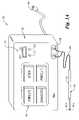
- FIG. 1Ais a perspective view of a front panel of an electrosurgical generator apparatus in accordance with a preferred embodiment of the present invention along with a bipolar surgical pen;
- FIG. 1Bis a perspective view of a rear panel of the electrosurgical generator of FIG. 1A ;
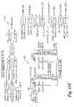
- FIG. 2Ais a general schematic block diagram of a control circuit for the electrosurgical generator of FIG. 1A ;
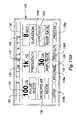
- FIG. 2Bis a circuit board interconnection diagram for the electrosurgical generator of FIG. 1A ;
- FIG. 3is a circuit schematic diagram of portions of front panel controls in accordance with the present invention.
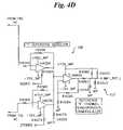
- FIGS. 4A–4Dare circuit schematic diagrams of an impedance detection circuit for the control circuit of FIG. 2A ;
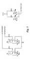
- FIGS. 5A–5Bare circuit schematic diagrams of a high voltage power supply and various sense circuit supplies for the control circuit of FIG. 2A ;
- FIG. 6A–6Care circuit schematic diagrams of a radio frequency (RF) amplifier and output driver for the control circuit at FIG. 2A ;
- RFradio frequency
- FIG. 7is a circuit schematic diagram of input/outputs for the control circuit of FIG. 2A ;
- FIG. 8is a circuit schematic diagram of isolated power supplies for the control circuit of FIG. 2A ;
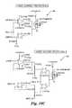
- FIG. 9is a circuit schematic diagram of a stimulator voltage/current control circuit for the control circuit of FIG. 2A ;
- FIGS. 10A–10Care circuit schematic diagrams of a patient output voltage/current regulator circuit for the control circuit of FIG. 2A ;
- FIGS. 11A–11Care circuit schematic diagrams of various sub-controllers for the control circuit of FIG. 2A ;
- FIG. 12A–12-Bare a circuit schematic diagrams of a main controller and various sub-controllers for the control circuit of FIG. 2A ;
- FIG. 13is a circuit schematic diagram of an output drive circuit for the control circuit of FIG. 2A ;
- FIG. 14is a circuit schematic diagram of a four-phase reference generator for the control circuit of FIG. 2A ;
- FIGS. 15A–15Gare screen diagrams for a touchscreen display of the electrosurgical generator of FIG. 1A ;
- FIG. 16is an overview diagram of the software screens of FIGS. 15A–15G ;
- FIG. 17is a flow chart depicting a synopsis of the software operation for impedance calculation for the control circuit of FIG. 2A ;
- FIGS. 18A–18Bare flow charts depicting a synopsis of the software operation for temperature/lesion control for the control circuit of FIG. 2A ;
- FIGS. 19A–19Care flow charts depicting a synopsis of the software operation for RF output control for the control circuit of FIG. 2A .
- a “lesion”is generally any pathological or traumatic discontinuity of tissue or loss of function of a part.
- Either a “coagulate mode” or a “cut mode”can be used to generate “lesions” when an electrosurgical RF generator is applied as a “lesion generator.”
- a coagulate modeuses a lower impedance output than a cut mode, about 70 ohms or less, but preferably about 20 ohms, so as not to cut tissue but only to coagulate blood.
- a coagulate modetypically outputs a decaying waveform. In neurosurgery or other nervous system procedures, a coagulate mode can be used to generate lesions.
- a cut modetypically uses a much higher impedance than a coagulate mode, such as about 300–500 ohms, but preferably about 400 ohms in order to cut tissue.
- a cut modegenerally uses a non-decaying waveform, such as a continuous sine wave.
- a coagulate modeis used to generate lesions, but the present invention can use cut mode or other different modes to generate lesions.
- a “stimulate mode” or “stimulator mode”is a lower voltage, power and impedance mode of operating an electrosurgical RF generator which does not cut or coagulate tissue or blood, but merely provides an electrical stimulus for nerves to detect, or cause to be detected, problematic areas of a patient.
- the electrosurgical RF generatorcan be described as being in a “lesion generate” mode wherein either cut mode or coagulate mode is selected as controlling the output of the electrosurgical RF generator instead of stimulate mode.
- An electrosurgical RF generator having the functions and features of the present inventioncould work equally as well in “coagulate and cut” (“normal”) applications as it could in “lesion generate and stimulate” (“lesion”) applications. Further, an electrosurgical RF generator having the functions and features of the present invention could also be applied to other electrosurgical RF generators of similar import and should not be considered limited to only the electrosurgical RF generators described herein.
- FIGS. 1A and 1Ba preferred embodiment of an electrosurgical RF generator apparatus or simply RF generator 50 in accordance with the present invention.
- FIG. 1Ais a perspective view of a front panel 52 a of the RF generator 50
- FIG. 1Bis a perspective view of a rear panel 52 b of the RF generator 50 .
- the RF generator 50operates in either cut mode or coagulate mode, and the RF generator 50 may also include a stimulate mode, especially when the cut mode and/or coagulate mode are used to generate lesions. Stimulate and lesion generate modes are typically associated with neurosurgery.
- the stimulate modeis generally used to detect problematic areas that may be causing a patient such symptoms as twitching or pain. Typically a surgeon or other user will apply a stimulate voltage to areas within a patient's brain until the twitching stops, thereby identifying the problematic area.
- the lesion generate modeis a higher power and impedance mode than the stimulate mode and is used to destroy, scar or otherwise render useless the detected problematic areas.
- the RF generatorhas jumpers JMP 3 , JMP 5 which allow selection between “normal” (cut/coagulate modes) and “lesion” (lesion generate/stimulate modes) as described in greater detail hereinafter.
- the RF generator 50includes a housing 52 , a touch panel 54 on the front panel 52 a and a connector panel 56 on the rear panel 52 b .
- a power cord 48 of the conventional type as is known in the artis connected to a power source to provide power to the RF generator 50 via a source power plug adapter 49 .
- the RF generator 50is supplied with between about 110–125 VAC at 60 Hertz (Hz) or about 220–240 VAC at 50 Hz alternating current (AC). But, other supply voltages and frequencies of AC voltage or other direct current (DC) voltages may be supplied without departing from the present invention.
- the RF generator 50is used with a bipolar surgical pen 40 having a cord 46 connected to an output adapter 58 of the RF generator 50 .
- the bipolar surgical pen 40typically includes a generally elongated insulated handle 42 which is sized to be gripped by a surgeon or other user and which contains a pair of spaced electrodes 44 a , 44 b .
- the electrodes 44 a , 44 bare preferably parallel to one another and partially extend from one end of the bipolar pen 40 .
- the electrodes 44 a , 44 bare each of opposite polarity such that one electrode is positively charged and the other electrode is negatively charged, alternately, during use.
- the electrodes 44 a , 44 bcan be of varying sizes, shapes and thicknesses depending upon the particular application.
- the RF generator 50is not limited to use with bipolar surgical pens 40 , but may be used with other electrosurgical instruments such as forceps, bulk coagulators, mono-polar electrodes with ground pads, and the like without departing from the broad inventive scope of the present invention.
- the RF generator 50also includes an on/off switch 53 ( FIG. 1A ) and RF indicator lights D 1 , D 2 .
- the on/off switch 53is preferably comprised of a two-way toggle type pushbutton having a blue cap for power on and a red cap for power off.
- the RF indicator lights D 1 , D 2are preferably blue light emitting diodes (LEDs), but could be other colors or types of lights without departing from the present invention.
- the on/off switch 53allows an RF output or a stimulation output to be activated by energizing/de-energizing a high voltage power supply 64 ( FIG. 2A ).
- front panel controls 57include an off pushbutton (PB) contact S 1 , an on PB contact S 2 for the on/off switch 53 ( FIG. 1A ) and first and second RF out LEDs D 1 , D 2 , respectively.
- the on and off PB contacts S 1 , S 2are single-pole, double-throw (SPDT) type pushbutton contacts.
- the off PB contact S 1is connected to an input of a main controller U 1 ( FIG. 12 ) to provide an off PB signal PBPWROFF
- the on PB contact S 2is connected to another input of the main controller U 1 to provide an on PB signal PBPWRON.
- the touch panel or touchscreen 54is a color, thin film technology (TFT), active matrix-type touchscreen of a type well known in the art.
- the touchscreen 54is controlled by a liquid crystal display (LCD) controller or simply display controller 60 ( FIG. 2A ) and provides inputs to the main controller U 1 through an SMT controller 62 ( FIG. 2A ) as described in greater detail below.
- LCDliquid crystal display
- SMT controller 62FIG. 2A
- an overall control circuit 59 for the RF generator 50is shown in a general block diagram.
- the control circuit 59is comprised of multiple sub-circuits forming an overall control system for the RF generator 50 .
- the control circuit 59includes the main controller U 1 and high and low voltage power supplies 64 , 66 .
- the RF generator 50includes the high voltage power supply 64 that is an off-line switching power supply to provide high voltage DC output to an RF amplifier circuit 68 .
- the high voltage (HV) power supply 64receives supply voltage (e.g., 120 VAC, 60 Hz) and serves as the power source for the low voltage power supply 66 and the RF amplifier 68 .
- the RF amplifier 68includes a stimulator portion 70 (sub-circuit) which applies reduced voltage amplitude or temperature output when selected through screens 120 – 126 ( FIGS. 15A–15G ) that interface to software in controllers U 1 , U 1102 , U 1120 and flash Random Access Memory (RAM) integrated circuit IC or flash memory IC U 1108 via the touch panel 54 described in greater detail hereinafter.
- a thermistor 72for providing the temperature of the tip of the surgical pen 40 to a temperature sense circuit 74 connected to the main controller U 1 .
- the touch panel 54is controlled by a liquid crystal display (LCD) or simply display controller 60 and is powered by an LCD or simply display CFL high voltage (HV) inverter 61 .
- LCDliquid crystal display
- HVhigh voltage
- Inputs from the touchscreen 54are interfaced through an SMT controller 62 .
- the SMT controller 62interfaces with the main controller U 1 .
- the front panel controls 57 and rear panel connectors 56provide input/output (I/O) to the control circuit 59 .
- the main controller U 1controls the stimulator circuit 70 and an RF amplifier circuit 68 .
- the RF amplifier circuit 68in combination with the HV power supply 64 in turn provide outputs to the bipolar surgical pen 40 .
- Feedback from the bipolar surgical pen 40is sensed by the thermistor 72 in combination with the temperature sense circuit 74 and by an impedance monitor circuit 76 .
- the various control circuits 56 , 57 , 60 , 61 , 62 , 64 , 66 , 68 , 70 , 72 , 74 , and 76 of the control circuit 59will hereinafter be described in greater detail.
- FIG. 2Bshows that the RF generator 50 comprises a plurality of circuit boards 154 , 155 , 156 , 157 , 157 a , 159 , 160 , 161 , 162 , 164 , 166 for each of the main functions shown in FIG. 2A .
- the RF generator 50comprises a plurality of circuit boards 154 , 155 , 156 , 157 , 157 a , 159 , 160 , 161 , 162 , 164 , 166 for each of the main functions shown in FIG. 2A .
- the RF generator 50includes a controller board 155 , a main board 159 , an LCD display panel board 154 , an SMT controller board 162 , a rear panel connectors board 156 , a front panel control board 157 , a front panel connectors board 157 a , an LCD display controller 160 , an LCD display inverter board 161 , a high voltage power supply board 164 and a low voltage power supply board 166 .
- Various cables and connectorsinterconnect the boards 154 , 155 , 156 , 157 , 157 a , 159 , 160 , 161 , 162 , 164 , 166 as is known in the art.
- the boards 154 , 155 , 156 , 157 , 157 a , 159 , 160 , 161 , 162 , 164 , 166are mounted in board slots (not shown) in a chassis (not shown) inside the housing 52 of the RF generator 50 and are interconnected as shown. But, some boards 154 , 155 , 156 , 157 , 157 a , 159 , 160 , 161 , 162 , 164 , 166 may be attached to other boards 154 , 155 , 156 , 157 , 157 a , 159 , 160 , 161 , 162 , 164 , 166 and/or to walls of the housing 52 as necessary.
- the control circuit 59could be implemented on a single circuit board or other various combinations of circuit boards and circuit implementations without departing from the present invention.
- the controller board 155includes an RF amplifier controller U 1102 , a digital to analog converter (DAC) IC U 1107 , an impedance monitor controller U 1120 and a flash memory IC U 1108 .
- the flash memory IC U 1108has no moving parts and can be electrically read, erased and programmed (programmable and non-volatile) without being taken out of the circuit as is well known in the art.
- the DAC IC U 1107includes at least four 8-bit channels or outputs and a 2-wire serial interface for receiving data. Other DAC ICs having different resolutions (bits of resolution) and different communications or other inputs may be provided without departing from the present invention.
- the controller board 155further includes a tone generator and drive circuit 98 and a master clock generator 95 .
- the master clock generator circuit 95includes an oscillator or crystal X 1 and first and second multi-stage binary ripple counters U 1150 and U 1160 . Regulated voltage, in this case (+) 5 volts DC ( FIG. 8 ), is applied to the crystal X 1 which generates a predetermined clock frequency output signal, in this case 40 MHz.
- the clock frequency output signal 40 MHzcan be used directly by the controllers U 1 , U 3 , U 1102 and U 1120 and other various sub-circuits circuits throughout the control circuit 59 , but the clock frequency output signal 40 MHz is also applied to a clock input of the first multi-stage binary ripple counter U 1150 and one stage Q 12 of the first binary ripple counter U 1150 is subsequently applied to a clock input of the second multi-stage binary ripple counter U 1160 to generate a plurality of frequencies which are multiples or divisions of the predetermined clock frequency output signal 40 MHz, such as 20 MHz, 156.25 KHz, 78.125 KHz, 9.766 KHz, 610 Hz, 305 Hz, 4.8 Hz and 2.4 Hz.
- the various clock frequencies 2.4 Hz-40 MHzare used by circuits throughout the control circuit 59 as is well known in the art.
- the tone generator and drive circuit 98generates, through a series of NAND gates U 1109 A–U 1109 C, U 1110 A–U 1110 B and U 1112 A–U 1112 B, a tone out signal TONEOUT which in turn drives an audio speaker LS 6001 ( FIG. 6C ).
- the tone generator and drive circuit 98receives a coagulation mode signal COAG from the main controller U 1 which is gated with the 305 Hz clock frequency and a foot pedal on signal FTPDON from the main controller U 1 in order to generate a tone of a particular frequency when the coagulation mode is selected and the foot pedal is pressed.
- the tone generator and drive circuit 98receives a cut mode signal CUT from the main controller U 1 which is gated with the 610 Hz clock frequency and with the foot pedal on signal FTPDON from the main controller U 1 in order to generate a tone of a different frequency from the coagulation mode when the cut mode is selected and the foot pedal is pressed. This provides the user with a different audible tone when either the cut or coagulation mode is being used.
- the cut mode signal CUTmay be gated with a blink signal BLINK, described in greater detail hereinafter, in order to create a cyclic output to the cut mode tone for differentiating the cut mode sound from a lesion mode sound when jumper JMP 3 selects the RF generator 50 to operate as a lesion/stimulate type generator instead of a cut/coagulate (normal) type generator.
- a touchpanel beep signal TPNL_BEEP from the main controller U 1is gated with the 1220 Hz clock frequency in order to generate yet another tone, different than the coagulation mode, the lesion mode and the cut mode tones, whenever the touchpanel 54 is touched as detected by the display controller U 3 .
- An audio circuit 89( FIG. 6C ) includes the speaker LS 6001 which is connected to the tone generator output TONEOUT and to a volume adjusting potentiometer VR 6001 for outputting sounds generally associated with the varying tone generator output signal TONEOUT.
- the controller board 155further includes several miscellaneous gating circuits for generating other signals used throughout the control circuit 59 .
- the 78.125 KHz and 156.25 KHz clock signalsare gated by an AND gate U 111 A to generate a simulate pulse signal STIM_PS.
- the stimulate pulse signal STIM_PSis used for as an excitation or control signal for the low voltage isolated supply circuit 66 ( FIG. 8 ).
- the 4.8 Hz and 2.4 Hz signalsare gated by an AND gate U 111 B to generate the blink signal BLINK.
- the blink signal BLINKprovides a relatively slow, cyclic pulse for use by other circuits such as indicator lights and the like.
- the foot pedal on signal FTPDONis gated with the blink signal BLINK by a NAND gate U 1110 C and subsequently gated with a relay on-delay signal RLYDLY by a NAND gate U 1115 B to generate an RF out flash signal RFOUTLED.
- the RF out flash signal RFOUTLEDis used to drive first and second RF out LEDs D 1 , D 2 .
- a monopolar mode relay output signal MONORLY_CTL from the main controller U 1is gated with the relay on-delay signal RLYDLY by a NAND gate U 1113 A to generate a monopolar mode relay signal MONORLY.
- the monopolar mode relay signal MONORLYenergizes a monomode relay K 1303 ( FIG.
- a high voltage relay output signal HVRLY_CTL of the main controller U 1is also gated with the relay on-delay signal RLYDLY by a NAND gate U 1113 B to generate a high voltage relay signal HVRLY.
- the high voltage relay signal HVRLYdrives a high voltage relay K 401 ( FIG. 5A ) in order to turn off supply power to DC level portions of the high voltage power supply 64 by the main controller U 1 when a short circuit condition or other predetermined alarm condition is detected.
- the cut mode signal CUT from the main controller U 1is also gated with the relay on-delay signal RLYDLY by a NAND gate U 1114 A to generate a cut relay signal CUTRLY.
- the cut relay signal CUTRLYcontrols an output mode relay K 6002 ( FIG. 6B ) to switch between output voltage levels as described in greater detail hereinafter.
- An impedance test output signal IMPD_TST from the main controller U 1is also gated with the relay on-delay signal RLYDLY by a NAND gate U 1114 B to generate an impedance test relay signal IMPTSTRLY.
- the impedance test relay signal IMPTSTRLYcontrols an impedance test relay K 6001 ( FIG. 6B ).
- the SMT controller board 162( FIG. 2B ) includes the main controller U 1 , a real time clock U 21 , and a display controller U 3 .
- the real time clock U 11021is used in conjunction with a battery back-up system (not shown).
- the main controller U 1is a complementary metal oxide semiconductor (CMOS) FLASH-based 8-bit microcontroller with 100 nanosecond instruction execution and includes about 1024 bytes of electrically erasable programmable read only memory (EEPROM), about 12 channels of 10-bit Analog-to-Digital (A/D) converter, an additional timer, external memory addressing, about two built-in comparators, a synchronous serial port which can be configured as either 3-wire serial peripheral Interface (SPI) or as 2-wire Inter-Integrated Circuit (I 2 C®) bus (a registered trademark of Philips Electronics, Eindhoven, NETHERLANDS) and about two addressable universal asynchronous receiver transmitters (AUSARTs).
- CMOScomplementary metal oxide semiconductor
- the main controller U 1could be other microcontrollers having other sizes and speeds, or the main controller U 1 could be an application specific integrated circuit (ASIC), a programmable logic array (PLA), a microprocessor and the like without departing from the present invention.
- the main controller U 1acts as a master controller to the other controllers U 3 , U 1102 and U 1120 .
- At least the main controller U 1uses at least the flash memory IC U 1108 to store and/or retrieve data, but the controllers U 3 , U 1102 and U 1120 may also use the flash memory IC U 1108 to store and/or retrieve data.
- An I 2 C busprovides two-wire serial communication between controllers U 1 , U 1102 and U 1120 , the DAC IC U 1107 , the real time clock U 11021 and the flash memory IC U 1108 .
- the I 2 C busis bi-directional and uses a serial data (SDA) line and a serial clock (SCL) line along with dedicated ports on a given controller for digital communication.
- the controllers U 1 , U 1102 and U 1120 , the DAC IC U 1107 , the real time clock U 11021 and the flash memory IC U 1108each have a unique address for I 2 C communications.
- Other inter-controller communicationsuch as straight I/O or other serial or parallel communications protocols may be used without departing from the present invention.
- the main controller U 1also provides a separate write protect signal WP to the flash memory IC U 1108 , in addition to the I 2 C bus communications, in order to issue write protect commands directly to the flash memory IC U 1108 .
- the main controller U 1also receives a real time clock interrupt signal RTC_IRQ ⁇ and a real time clock sequential write signal RTC_SQW, in addition to the I 2 C bus communications, in order to interrupt the main controller U 1 for more precise real time updates.
- the main controller U 1communicates with the display controller U 3 serially via touchpanel ready to send TPNL_RTS, touchpanel clear to send TPNL_CTS, and touch panel transmit TPNL_TXD signals.
- the main controller U 1also provides data to the touchpanel 54 through the display control circuit 60 via video data signals VIDEO_D 0 –VIDEO_D 7 and communicates directly with the display control circuit 60 via communications signals including video clear to send VIDEO_CS ⁇ , video ready VIDEO_RDY ⁇ and video write VIDEO_WR.
- the display control circuit 60allows the main controller U 1 to display data such as current timer ⁇ counter ⁇ setpoint presets, measured process values and the like.
- the display controller U 3detects actual presses of the touchpanel 54 at specific locations and times in order to determine what feature or button a user has selected or entered on a particular screen ( FIGS. 15A–15H ).
- the SMT controller board 162further includes filtering capacitors C 1 –C 4 , a sense X-left resistor R 2 , a sense Y-top resistor R 3 , a sense Y-bottom resistor R 4 , a sense X-right resistor R 5 , a biasing capacitor C 7 , and an external crystal or oscillator Y 1 , which together support the display controller U 3 .
- the touchscreen 54communicates with at least the main controller U 1 through display controller U 3 in order to display data from the memory and to allow a user to enter settings.
- the sense resistors R 2 –R 5connect to touch panel cables 3M TP, GUNZI TP and provide voltage inputs to the display controller U 3 at inputs SXL, SYT, SYB, and SXR, respectively.
- the RF amplifier controller U 1102drives a pair of shift registers U 1130 , U 1140 to generate declining pulse duration modulated (PDM) RF outputs.
- the shift registers U 1130 , U 1140generate about one MHz declining PDM RF outputs.
- the shift registers U 1130 , U 1140are 8-bit shift registers. It is to be understood by those skilled in the art that a 16-bit shift register or other sized shift registers could be used without departing from the scope and spirit of the present invention.
- the shift registers U 1130 , U 1140provide a series of output pulses at about a 0.5 microsecond rate and/or multiples and derivatives thereof.
- the RF amplifier controller U 1102shifts the input load (data lines B 0 –B 7 ) of the shift registers U 1130 , U 1140 to produce pulses which are out of phase from one another at a given rate, in this case at about a 1 MHz rate or an 833 MHz rate as described hereinafter ( FIGS. 18A–18C ).
- the RF amplifier controller U 1102in combination with a 20 MHz clock signal from the master clock generator 95 , causes the shift registers U 1130 , U 1140 to have the following pulse waveform pattern: about 2 microseconds on, about 0.5 microseconds off, about 1.5 microseconds on, about 1 microsecond off; about 1 microsecond on, about 1.5 microseconds off; about 0.5 microseconds on, about 2 microseconds off.
- the total duration for the entire waveformis about 10 microseconds.
- the resulting waveformis a decaying square wave which is filtered to form a decaying sine wave as described hereafter.
- the shift registers U 1130 , U 1140drive a pair of field effect transistor (FET) drivers U 6001 , U 6002 in the RF amplifier circuit 68 shown on FIG. 6A with their respective shift register outputs Q 1 MHZ and Q ⁇ 1 MHZ.
- FETfield effect transistor
- the first and second shift register outputs Q 1 MHZ and Q ⁇ 1 MHZare also inputs back into the RF amplifier controller U 1102 .
- the first shift register output Q 1 MHZis about 180° out of phase with the second shift register output Q ⁇ 1 MHZ.
- the RF amplifier controller U 1102which is controlled by the main controller U 1 includes an controlling program that generates a plurality of different user selectable waveforms based on PDM modulation of the carrier signal ( FIGS. 19A–19C ).
- the RF amplifier circuit 68is substantially disposed on the main board 159 .
- the RF amplifier circuit 68includes Zener diodes D 6002 , D 6004 –D 6006 , D 6008 –D 6009 and D 6012 –D 6015 , diodes D 6016 –D 6017 , diodes D 6001 and D 6007 , and D 6010 –D 6011 , transformer T 6001 , capacitors C 6001 –C 6002 , FET drivers U 6001 and U 6002 , and field effect transistors (FETs) Q 6001 and Q 6002 .
- FETsfield effect transistors
- the FETs Q 6001 , Q 6002 in combination with the FET drivers U 6001 , U 6002 and the three winding transformer T 6001form the amplifier portion of the RF amplifier circuit 68 .
- the RF amplifier circuit 68amplifies the output signals Q 1 MHZ, Q ⁇ 1 MHZ from the shift registers U 1130 , U 1140 .
- the output signals Q 1 MHZ, Q ⁇ 1 MHZ from the shift registers U 1130 , U 1140drive the FET drivers U 6001 and U 6002 which in turn drive the FETs Q 6001 , Q 6002 .
- the FETs Q 6001 , Q 6002are fast switching metal oxide semiconductor FETs (MOSFETs) with about 500 V breakdown voltages and current ratings of about 15 A.
- the FETs Q 6001 , Q 6002switch a regulated high voltage REG HV ( FIG. 5B ) to first and second primary windings T 6001 a , T 6001 b , respectively of the transformer T 6001 .
- the RF amplifier circuit 68further includes a snubber portion 80 connected to the primary windings T 6001 a , T 6001 b of the amplifier transformer T 6001 via a resistor and Zener diode bridge 81 which includes an FET Q 6003 and diodes D 6016 , D 6017 .
- the snubber portion 80prevents or reduces high inductive spiking of voltages and controls switching voltage transients, as is well known in the art.
- the RF amplifier circuit 68further includes inductors L 6002 –L 6006 in combination with an isolation transformer T 6002 which form the RF output and filter 69 of the RF amplifier 68 .
- the RF output and filter 69filters the waveforms from the FETs Q 6001 and Q 6002 in order to achieve waveforms closer to or approximating sinusoidal and also provides signal isolation in order to reduce RF leakage.
- the isolation transformer T 6002is a toroid-type transformer.
- the overall impedance on the secondary side of the isolation transformer T 6002is a function of the secondary winding of transformer T 6002 , inductor L 6005 and capacitor C 6008 , and is selected or modified by changing component values in order to configure the RF amplifier circuit 69 for cut mode or coagulate mode.
- the impedance of the output of the RF amplifieris preferably about 400 ohms for cut mode and about 20 ohms or less for coagulate mode. While only one RF output and filter circuit 69 is shown in FIG.
- RF amplifier 68shown in FIGS. 6A–6B is simplified for use as a lesion generator so that the impedance of the output of the RF amplifier could be chosen to be a cut mode or a coagulate mode in order to generate lesions. Since the output waveform is controlled by the RF amplifier controller U 1102 (i.e., via software) either type of output signal, decaying or continuous, can be selected.
- the RF amplifier circuit 68further includes a short circuit detection circuit 78 which is connected to the RF output and filter 69 by inductor L 6006 .
- the short circuit detection circuit 78generally determines when the output current exceeds a predetermined threshold current as set by the main controller U 1 .
- the short circuit detection circuit 78includes operational amplifier (op-amp) U 6003 A, diodes D 6007 , D 6010 –D 6011 , capacitors C 6010 , C 6013 , C 6017 –C 6018 and resistors R 6009 , R 6014 .
- the threshold of the short circuit detection circuit 78is controlled by the main controller U 1 by analog output signals from the DAC IC U 1107 which is controlled via the I 2 C bus.
- the DAC IC U 1107generates an RF short circuit control signal CAOGRFSCCTL which corresponds to the predetermined threshold current in the main controller U 1 and which is applied to the positive input of op-amp U 6003 A wherein op-amp U 6003 A is applied as a comparator.
- Current in the RF output and filter 69is detected through inductor L 6006 and the resistor R 6009 and capacitors C 6013 and C 6010 filter or smooth the detected signal.
- Diodes D 6010 , D 6011allow a reduced voltage, in this case +15V, to be piloted by the detected current thereby applying an equivalent level current at a lower voltage through resistor R 6015 and a corresponding voltage is then applied to the negative input of comparator U 6003 A.
- the output of comparator U 6003 Ais an RF short circuit signal RFSC_COAG which, if present, is supplied to an input of the RF amplifier controller U 1102 . If the RF amplifier controller U 1102 receives the RF short circuit signal RFSC_COAG for a predetermined period of time, the RF amplifier controller U 1102 will shut-off outputs to the RF amplifier circuit 68 and high voltage power supply circuit 64 and send a signal to the main controller U 1 for alarming and the like.
- FIG. 6Bshows that the output mode relay K 6002 selects between the output of RF output and filter 69 of the RF amplifier circuit 68 and a stimulation signal which includes stimulate signals STIMOUT 1 , STIMOUT 2 ( FIG. 13 ).
- the coil of the output mode relay K 6002is controlled by the cut relay signal CUTRLY derived from NAND gates U 1114 A, U 1114 B and the cut output signal CUT from the main controller U 1 .
- the impedance monitor interface 76is connected in parallel with the RF output and filter 69 of the RF amplifier circuit 68 .
- the impedance monitor interface 76includes inductors L 6007 –L 6011 and capacitors C 6011 –C 6012 and C 6014 –C 6016 which form a diplexer for filtering out a particular signal between two mixed signals as described in greater below.
- the controller board 155( FIG. 2B ) further includes the impedance monitor controller U 1120 ( FIG. 11B ) which is coupled to the impedance monitor interface 76 ( FIG. 6B ).
- the impedance monitor controller U 1120is a separate microcontroller which communicates with the main controller U 1 via the I 2 C bus as mentioned above.
- the impedance monitor interface 76is in electrical communication with an impedance monitor circuit 90 ( FIGS. 4A–4D ).
- the impedance monitor circuit 90includes a reflectometer bridge 92 , a bridge signal conditioner 94 and four detector circuits, namely a quadrature bridge or Q-bridge detector 100 , an in-phase bridge or I-bridge detector 102 , an quadrature reference or Q-reference detector 104 , and an in-phase reference or I-reference 106 .
- a sine reference signal 20 KHZ_REF from a reference signal generator 108 ( FIG. 14 )is applied to the reflectometer bridge 92 .
- the sine reference signal 20 KHZ_REFis about 18 to 24 kHz, but preferably, the sine reference signal 20 KHZ_REF is about 20 kHz.
- the sine reference signal 20 KHZ_REFprovides an excitation signal, i.e., impedance monitor drive signals IMPMONI_DRV+, IMPMONI_DRV ⁇ , for measuring impedance over the electrodes 44 a , 44 b of the bipolar surgical pen 40 .
- the impedance monitor drive signals IMPMONI_DRV+, IMPMONI_DRV ⁇are applied to the bipolar surgical pen 40 through the impedance monitor interface 76 ( FIG. 6B ) thereby superimposing the impedance monitor drive signals IMPMONI_DRV+, IMPMONI_DRV ⁇ onto a given cut/coagulate signal (i.e., the output of RF output and filter 69 ).
- the impedance monitor interface 76functions as a filter-type diplexer which selectively removes an impedance signal to be measured from the cut or coagulation signal from the RF output circuit 69 .
- the impedance monitor drive signals IMPMONI_DRV+, IMPMONI_DRV ⁇therefore, the impedance affects the conditioned form of the sine reference signal 20 KHZ_REF which is applied to the bridge detectors 100 , 102 through the bridge signal conditioning circuit 94 .
- resistor R 6001simulates a fixed value on the impedance monitor drive/feedback signals IMPMONI_DRV+, IMPMONI_DRV ⁇ .
- resistor R 6001is a precision resistor with a tolerance of about 1% or better.
- resistor R 6001could be selected with other tolerances and other resistance values without departing from the present invention.
- resistor R 6001is a variable resistance device such as a multi-resistor switch-selectable block for generating user selectable voltages when testing the overall RF generator 50 .
- the Q-bridge detector 100includes transconductance op-amps U 4023 and U 4024 , op-amp U 4025 , resistors R 4032 , R 4034 , R 4036 , R 4038 , R 4040 , R 4042 , R 4043 , R 4046 –R 4048 and R 4050 , capacitors C 4043 and C 4045 , and diodes D 4060 and D 4070 .
- Impedance monitor feedback signals IMPMONI_DRV+, IMPMONI_DRV ⁇ conditioned via the bridge conditioning circuit 94are applied to transconductance op-amps U 4023 and U 4024 of the Q-bridge detector 100 .
- the Transconductance op-amp U 4023also receives a 180° signal 180 DEG from a four phase reference generator 108 ( FIG. 14 ) so that the output of the transconductance op-amp U 4023 is only permitted when the 180° signal 180 DEG is on.
- the transconductance op-amp U 4024also receives a 0° signal 0 DEG from the four phase generator 108 so that the output of the transconductance op-amp U 4024 is only permitted when the 0° signal 0 DEG is on.
- transconductance op-amps U 4023 , U 4024are alternately, based on phase angle signals 0° signal 0 DEG and 180° signal 180 DEG, input to op-amp U 4025 and subsequently to a low pass filter comprising the resistor R 4036 and capacitor C 4043 which together form a bridge Q-channel synchronous demodulator 101 .
- the bridge Q-channel synchronous demodulator 101outputs a Q-channel bridge signal IMP_BRDG_Q to the main controller U 1 and the impedance monitor controller U 1120 .
- the Q-bridge signal IMP_BRDG_Qgenerally corresponds to the overall imaginary component of the impedance at the electrodes 44 a , 44 b.
- the I-bridge detector 102includes transconductance op-amps U 4026 and U 4027 , op-amp U 4028 , resistors R 4033 , R 4035 , R 4037 , R 4039 , R 4041 , R 4044 –R 4045 , R 4049 , R 4071 , R 4072 , and R 4083 , capacitors C 4044 and C 4046 , and diodes D 4008 and D 4009 .
- Impedance monitor feedback signals IMPMONI_DRV+, IMPMONI_DRV ⁇ conditioned via the bridge signal conditioner 94are also applied to transconductance op-amps U 4026 , U 4027 .
- the Transconductance op-amp U 4026also receives a 90° signal 90 DEG from the four phase reference generator 108 so that the output of the transconductance op-amp U 4026 is only permitted when the 90° signal 90 DEG is on.
- the transconductance op-amp U 4027also receives a 270° signal 270 DEG from the four phase generator so that the output of the transconductance op-amp U 4027 is only permitted when the 270° signal 270 DEG is on.
- transconductance op-amps U 4026 , U 4027are alternately, based on phase angle signals for 90° signal 90 DEG and 270° signal 270 DEG, input to the op-amp U 4028 .
- the output of op-amp U 4028is applied to a low pass filter that includes resistor R 4037 and capacitor C 4044 .
- the op-amp U 4028 and the low pass filterform a bridge I-channel synchronous demodulator 103 .
- the bridge I-channel synchronous demodulator 103outputs an I-channel bridge signal IMP_BRDG_I to the main controller U 1 and the impedance monitor controller U 1120 .
- the I-bridge signal IMP_BRDG_Igenerally corresponds to the overall real component of the impedance at the electrodes 44 a , 44 b.
- the Q-reference detector 104includes transconductance op-amps U 4031 and U 4032 , op-amp U 4033 , resistors R 4057 , R 4059 , R 4061 , R 4063 , R 4065 , R 4067 –R 4068 , R 4073 , R 4079 , R 4080 and R 4081 , capacitors C 4047 and C 4049 , and diodes D 4010 and D 4011 .
- the sine reference signal 20 KHZ_REFis also dropped across a resistor R 4030 to create an alternate sine reference signal 20 KHZ_REF_A.
- the alternate sine reference signal 20 KHZ_REF_Ais applied to reference signal conditioner 96 .
- the reference signal conditioner 96comprises op-amps U 4029 , U 4030 and resistors R 4051 , R 4055 –R 4056 .
- the conditioned signal output from the reference signal conditioner 96is applied to the transconductance op-amps U 4031 , U 4032 .
- the transconductance op-amp U 4031also receives the 180° signal 180 DEG from the four phase reference generator 108 so that the output of the transconductance op-amp U 4031 is only permitted when the 180° signal 180 DEG is on.
- the transconductance op-amp U 4032also receives the 0° signal 0 DEG from the four phase generator 108 so that the output of the transconductance op-amp U 4032 is only permitted when the 0° signal 0 DEG is on.
- the outputs of the transconductance op-amps U 4031 , U 4032are alternately, based on phase angle signals 0° signal 0 DEG and 180° signal 180 DEG, input to the op-amp U 4033 and a low pass filter including resistor R 4061 and capacitor C 4047 which form a reference Q-channel synchronous demodulator 105 .
- the reference Q-channel synchronous demodulator 105outputs a Q-channel reference signal IMP_REF_Q to the main controller U 1 and the impedance monitor controller U 4020 .
- the Q-channel reference signal IMP_REF_Qgenerally corresponds to the imaginary component of the reference signal which is used to compensate out the impedance of the electrodes 44 a , 44 b themselves from the overall imaginary component of the measured impedance.
- the reference signal conditioner 96also provides an input to the I-reference detector 106 .
- the I-reference detector 106includes transconductance op-amps U 4034 and U 4035 , op-amp U 4036 , resistors R 4058 , R 4060 , R 4062 , R 4064 , R 4066 , R 4069 , R 4070 , R 4074 , R 4082 and R 4084 –R 4085 , capacitors C 4048 and C 4050 , and diodes D 4012 and D 4013 .
- the output of the reference signal 96is applied to the inputs of transconductance op-amps U 4034 , U 4035 .
- the transconductance op-amp U 4034also receives the 90° signal 90 DEG from the four phase reference generator 108 so that the output of the transconductance op-amp U 4034 is only permitted when the 90° signal 90 DEG is on.
- the transconductance op-amp U 4035also receives the 270° signal 270 DEG from the four phase generator 108 so that the output of the transconductance op-amp U 4035 is only permitted when the 270° signal 270 DEG is on.
- the outputs of the transconductance op-amps U 4034 , U 4035are alternately, based on phase angle signals for 90° signal 90 DEG and 270° signal 270 DEG, input to the op-amp U 4036 .
- the output of the op-amp U 4036is passed through a low pass filter including resistor R 4062 and capacitor C 4048 which together form a reference I-channel synchronous demodulator 107 .
- the reference I-channel synchronous demodulator 107outputs an I-channel reference signal IMP_REF_I to the main controller U 1 and the impedance monitor controller U 1120 .
- the I-channel reference signal IMP_REF_Igenerally corresponds to the real component of the reference signal which is used to compensate out the actual impedance of the electrodes 44 a , 44 b themselves from the overall real component of the measured impedance.
- the combination of the synchronous detectors 100 , 102 , 104 , 106is used to detect the angle and magnitude or complex impedance measured through the bipolar electrodes 44 a , 44 b of the electrode pen 40 .
- the overall impedance monitor 90samples at 0°, 90°, 180°, 270° phase angles of a signal returned from the electrodes 44 a , 44 b via the impedance monitor feedback signals IMPMONI_DRV+, IMPMONI_DRV ⁇ .
- an impedance calculation software routine 198( FIG. 17 ) is able to calculate the actual impedance of the material being cut or coagulated (in real and imaginary Cartesian coordinates) from the overall impedance (real and imaginary Cartesian coordinates) and the reference signal impedance (real and imaginary Cartesian coordinates) by compensating out the impedance of the electrodes 44 a , 44 b themselves.
- the impedance calculation software routine 198then converts the actual complex impedance in terms of real and imaginary components into magnitude and phase angle of the actual impedance (Polar coordinates). The magnitude and phase angle of the actual impedance can then be monitored, trended, used for alarming and/or used to stop a particular procedure separately or together.
- a high voltage power supply 64in accordance with the preferred embodiment of the present invention which is generally disposed on the high voltage power supply board 164 .
- Conventionally available alternating currente.g., about 120 VAC, 60 Hz
- the supplied AC poweris smoothed through a capacitor C 400 before being applied to a diode bridge rectifier DB 400 .
- the output of a full wave diode bridge rectifier DB 400is clamped by an in-rush limiter RT 400 which provides a signal to contacts of a high voltage power supply relay K 401 .
- the high voltage relay K 401is controlled by the high voltage relay signal HVRLY which is generated by the high voltage relay output signal HVRLY_CTL of the main controller U 1 gated with the relay on-delay signal RLYDLY.
- Capacitors C 401 , C 402smooth the full wave rectified signal from the full wave diode bridge rectifier DB 400 and resistor R 400 provides a bleed-off when the relay K 401 is opened.
- high voltage relay K 401applies DC voltage to a second fuse F 401 and the rest of the high voltage power supply circuit 64 .
- An optically isolated transistor U 400 in combination with a diode D 401 and resistor R 401detect when there is a no high voltage condition and provide a no high voltage signal NOHV to an input of the main controller U 1 .
- Current sense transformer T 400 in combination with suitable biasing components including resistors R 413 and R 405 , diode D 407 and filtering capacitor C 416create a current sense signal ISENS.
- a high voltage regulating circuit 65is also powered through another fuse F 401 .
- the high voltage regulating circuit 65includes a FET driver IC U 402 and a high speed pulse width modulating controller (PWM controller) U 401 .
- the current sense signal ISENSis applied to a current limiting input of the PWM controller U 401 for clamping or limiting the output of the PWM controller U 401 .
- An RC oscillatorcomprising resistor R 407 and capacitor C 403 serves as a clock for the PWM controller U 401 .
- the foot pedal signal FTPDON from the main controller U 1FIG.
- transistor Q 400gates transistor Q 400 through resistor R 402 , and transistor Q 400 allows +15V across resistor R 403 thereby allowing a FET Q 401 , with a suitable filtering capacitor C 405 , to allow a soft start sink signal to flow to ground thereby selecting a soft start function (ramp up) in the PWM controller U 401 .
- the output of the PWM controller U 401is applied directly to a high input of the FET driver IC U 402 and to a FET Q 404 for gating the low input of the FET driver IC U 402 .
- the high and low outputs HO, LO of the FET driver IC U 402along with suitable biasing components including capacitors C 412 –C 415 , C 417 –C 418 , resistors R 410 –R 412 , diodes D 402 –D 406 , an inductor L 400 , drive high MOSFET Q 402 and low MOSFET Q 403 , respectfully to generate the regulated high voltage signal REG HV.
- the regulated high voltage signal REG HVis applied to the RF amplifier 68 ( FIGS. 6A and 6B ) to provide cut and/or coagulate output signals to the electrodes 44 a , 44 b .
- a power supply control signal PSCTLVis output of the DAC IC U 1107 ( FIG. 11B ) and is controlled or adjusted by the main controller U 1 .
- the power supply control signal PSCTLVis applied to op-amp U 403 B with associated biasing components including resistors R 415 , R 417 –R 419 , capacitor C 419 and diode D 408 .
- the output of op-amp U 403 Bis applied to op-amp U 403 A with associated resistors R 420 –R 422 and capacitors C 420 –C 421 and the output of op-amp U 403 A is then applied to a voltage regulating input of the PWM controller U 401 in order to adjust the PWM output of the PWM controller U 401 .
- the main controller U 11021drives the DAC IC U 1107 which drives the PWM controller U 401 .
- the PWM controller U 401drives the FET driver IC U 402 which pulse width modulates FETS Q 402 and Q 403 to generate the regulated high voltage REGHV for use by the RF amplifier circuit 68 .
- a change in the power supply control signal PSCTLVcauses a proportional change in the regulated high voltage REGHV being output from the high voltage power supply 64 .
- Other circuit implementations for generating regulated high voltage DCsuch as the regulated high voltage power supply disclosed in U.S. Pat. No. 5,318,563 of Malis et al., may be utilized without departing from the broad inventive scope of the present invention.
- the high voltage power supply 64also includes an over voltage monitoring circuit 82 .
- the over voltage monitoring circuit 82includes op-amps U 405 C–U 405 D and resistors R 438 –R 446 and generates an over voltage monitor signal OVMONI to the main controller U 1 when the regulated high voltage REGHV has exceeded a predetermined value for alarming and/or interlocking purposes. For example, if an over voltage condition is detected, the main controller U 1 can either reduce the power supply control voltage PSCTLV or de-energize the high voltage relay K 401 via the high voltage relay output signal HVRLY_CTL.
- a data output circuit 30includes an RS 232 line driver IC U 6004 , various biasing capacitors C 6019 and C 6021 –C 6024 and a data output port P 6013 .
- a serial data out signal DATA_OUT from the main controller U 1is applied to the RS 232 line driver IC U 6004 .
- the RS 232 line driver IC U 6004converts the serial data out signal DATA_OUT to a corresponding RS 232 compliant signal TXD on pin 2 of the data output port P 6013 .
- the data output port P 6013is preferably a 25 pin DIN connector of the DB-25 type; however, the data output port P 6013 could be other connector types such as a 9 pin DIN connector of the DB-9 type or even other connectors without departing from the present invention. Further, it is obvious that a receive signal (not shown) could be connected from the data output port P 6013 to the RS 232 line driver IC U 6004 and from the RS 232 line driver IC U 6004 to the main controller U 1 in order to also receive data as is well know in the art. Even further, other line drivers such as RS 485 , Ethernet and the like may be substituted for the RS 232 line driver IC U 6004 along with appropriate associated circuitry necessary to make the other line drivers functional within the context shown herein without departing from the present invention.
- a foot pedal detection circuit 32includes an input jack J 6008 and conditioning inductors L 6012 –L 6013 .
- a foot pedal switch set(not shown) is normally connected to the input jack J 6008 to allow a user, such as a surgeon, to use the different modes of operation of the RF generator 50 without using his or her hands because users are typically holding at least the surgical pen 40 during a particular procedure.
- a coagulation mode foot pedal signal COAG_FTPDLis conditioned by inductor L 6014 when a coagulation foot pedal switch is closed or otherwise operated.
- a cut mode foot pedal signal CUT_FTPDLis conditioned by inductor L 6013 when a cut foot pedal switch is closed or otherwise operated.
- a lavage foot pedal signal LAVA_FTPDLis conditioned by inductor L 6012 when a lavage foot pedal switch is closed or otherwise operated.
- the coagulation mode foot pedal signal COAG_FTPDL, the cut mode foot pedal signal CUT_FTPDL and the lavage foot pedal signal LAVA_FTPDLare all connected to a foot pedal interface circuit 33 on the controller board 155 ( FIG. 11B ).
- the foot pedal interface circuit 33includes resistors R 1152 –R 1154 , capacitors C 1151 –C 1153 and diodes D 1103 –D 1105 .
- a fixed voltageis applied across the resistors R 1152 –R 1154 , in this case (+) 5 volts DC, and is applied to each signal line for the coagulation mode foot pedal signal COAG_FTPDL, the cut mode foot pedal signal CUT_FTPDL and the lavage foot pedal signal LAVA_FTPDL, respectively.
- currentflows through the respective switch to ground thereby allowing the capacitors C 1151 –C 1153 to discharge through respective inductors L 1112 –L 1113 and allowing the voltage to drop on the other side of diodes D 1103 –D 1105 .
- Signals COAGFTPDL, CUTFTPDL, and LAVAFTPDL corresponding to the coagulation mode foot pedal signal COAG_FTPDL, the cut mode foot pedal signal CUT_FTPDL and the lavage foot pedal signal LAVA_FTPDL, respectively,are connected to diodes D 1103 –D 1105 and are connected to inputs of the main controller U 1 on the SMT controller board 162 .
- the main controller U 1determines, through various software, if a particular mode is applicable based upon the input signals for the coagulation mode foot pedal signal COAGFTPDL, the cut mode foot pedal signal CUTFTPDL, and the lavage foot pedal signal LAVAFTPDL and other present conditions and provides output signals for use by various other circuits for coagulation mode signal COAG, cut mode signal CUT, lavage mode signal LAVAGE.
- the main controller U 1determines when any of the input signals for coagulation mode foot pedal signal COAGFTPDL, cut mode foot pedal signal CUTFTPDL, and lavage foot pedal signal LAVAFTPDL indicate that a foot pedal switch is closed and outputs a foot pedal on signal FTPDON for use by at least the PWM controller U 401 , the RF amplifier controller U 1102 and the tone generator 98 .
- the controller board 155further includes the temperature sense or thermistor interface circuit 74 as shown on FIG. 7 .
- the thermistor interface 74includes resistors R 701 , R 702 , capacitors C 717 , inductor L 705 , diode D 701 , NOT gate U 715 A and relay K 701 .
- a voltage referencein this case 5 volts DC, is applied to the thermistor 72 across resistor R 701 providing excitation voltage for the thermistor 72 .
- the thermistorgenerates a temperature input voltage signal THRMSTR which is conditioned by the temperature sense control circuit 74 which varies generally linearly with variations in temperature to a practical extent, as is known in the art.
- the other terminal of the thermistor 72is tied to an alternate voltage sink AVSS which is merely an alternative resistive path (resistor R 6 on FIG. 12 ) to ground.
- the NAND gate U 715 Aselectively energizes the temperature test relay K 701 whenever the startup delay relay signal RLYDLY from a power on-delay circuit 75 or a temperature test signal TEMP_TST from the main controller U 1 are high.
- resistor R 702simulates a fixed value on the temperature input voltage signal THRMSTR.
- resistor R 702is a precision resistor with a tolerance of about 1% or better.
- resistor R 702has a resistance value which generally corresponds to a resistance value generated by the thermistor 72 when the temperature is about 40° C.
- resistor R 702could be selected with other tolerances and other resistance values without departing from the present invention.
- resistor R 702is a variable resistance device such as a multi-resistor switch-selectable block for generating user selectable voltages when testing the overall PF generator 50 .
- the power on-delay circuit 75includes a resistor R 706 , a capacitor C 720 and a diode D 702 .
- a fixed voltage, in this case (+) 5 volts DCis applied across resistor R 706 in order to charge capacitor C 720 .
- the power on-delay circuit 75provides the startup delay relay signal RLYDLY after capacitor C 720 is fully charged.
- the startup delay relay signal RLYDLYis used throughout the control circuit 59 to reset various circuits and/or devices on power up and to prevent unexpected events from occurring on power up (of the overall control circuit 59 ) because various circuits and/or controllers are in unexpected conditions just after power up.
- Other circuit implementationssuch as timer IC's or timer controlled relays may be used in place of the power on-delay circuit 75 to generate the startup delay relay signal RLYDLY without departing from the present invention.
- a voltage regulator IC U 701provides a regulated 5 VREF for use throughout the control circuit 59 .
- the voltage regulator IC U 701accepts +15 volts DC and, along with suitable biasing components including capacitors C 718 –C 719 and resistor R 703 , generates the regulated 5 volts DC 5 VREF.
- the low voltage isolated supply 66provides regulated low voltage outputs of approximately (+) 3–7 volts DC, (+) 12–15 volts DC, and ( ⁇ ) 12–15 volts DC.
- the output of the isolated supply 66has outputs of (+) 5 volts DC+ 5 VAUX, (+) 15 volts DC+ 15 AUX and ( ⁇ ) 15 volts DC ⁇ 15 VAUX.
- Isolated supply 66includes a dual-ended transformer T 803 and a voltage regulator IC U 110811 .
- the isolated supply 66also includes capacitors C 840 –C 843 , resistors R 837 –R 838 , diodes D 818 and D 820 , and clipper diode D 819 .
- the stimulate pulse signal STIM_PSgates the transistor Q 806 at a frequency set by the 78.125 KHz and 156.25 KHz clock signals so that an alternating signal can be created with clipper diode D 819 to drive the primary winding of transformer T 803 .
- the diode D 818 and capacitor C 842provide the (+) 15 volts DC+ 15 AUX.
- the oppositely oriented diode D 820 and capacitor C 843provide the ( ⁇ ) 15 volts DC ⁇ 15 VAUX.
- the voltage regulator IC U 110811provides a more precisely regulate (+) 5 volts DC+ 5 VAUX from the (+) 15 volts DC+ 15 AUX.
- the regulated voltages (+) 5 volts DC+ 5 VAUX, (+) 15 volts DC+ 15 AUX and ( ⁇ ) 15 volts DC ⁇ 15 VAUXare used throughout the control circuit 59 as low voltage supply as is known in the art.
- the main board 159further includes a stimulator voltage control circuit 111 and a stimulator current control circuit 112 of the stimulator circuit 70 .
- the stimulator voltage control circuit 111includes opto-coupler IC U 909 and op-amps U 908 B and U 908 C. Positive (+) 5 volts is applied through a resistor capacitor network comprising resistor R 925 and capacitor C 931 to the anode of opto-coupler IC U 909 and a stimulator voltage control signal STIMVCTL output from the main controller U 1 is applied to the cathode of opto-coupler U 909 .
- the outputis directed across resistor R 929 and capacitor C 932 to drive transistor Q 904 the output of which is dropped across resistors R 927 –R 928 with suitable filtering capacitors C 928 , C 930 , C 933 –C 934 to the input of op-amp U 908 B.
- the output of op-amp U 908 Bis applied to the input of op-amp (buffer) U 908 C with suitable biasing resistors R 930 –R 931 .
- the output of op-amp U 908 Bis a stimulate voltage set VSET voltage and the output of op-amp U 908 C is stimulate voltage reference VREF.
- the stimulator current control circuit 112includes opto-coupler IC U 910 and op-amps U 908 A and U 908 D. Similar to the stimulator voltage control circuit 111 , positive (+) 5 volts is dropped across resistor R 932 and capacitor C 937 to the anode of opto-coupler IC U 910 and a stimulator current control signal STIMICTL output from the main controller U 1 is applied to the cathode of opto-coupler U 910 . The output of opto-coupler IC U 910 is dropped across resistor R 936 and capacitor C 938 to drive transistor Q 905 .
- the output of transistor Q 905 in combination with resistors R 933 –R 935 and capacitors C 936 and C 939apply the input voltage to op-amp (buffer) U 908 A.
- the output of op-amp U 908 Ais applied to the input of op-amp (buffer) U 908 D, and the output of op-amp U 908 D provides a current reference voltage IREF.
- the stimulator circuit 70further includes a patient output voltage/current regulator or patient regulator 86 .
- the patient regulator 86includes op-amps U 1012 A–U 1012 B, transistors Q 1007 –Q 1010 and suitable biasing components including resistors R 1039 –R 1044 and R 1046 –R 1049 , capacitors C 1045 –C 1050 and diodes D 1021 –D 1022 .
- the current reference voltage IREF( FIG. 9 ) from the stimulator current control circuit 112 is applied to op-amp U 1012 B and the output of op-amp U 1012 B is dropped across resistor R 1046 to drive a transistor amplifier bridge Q 1008 –Q 1010 .
- the stimulate voltage reference VREF( FIG. 9 ) from the stimulator voltage control circuit 111 is applied to op-amp U 1012 A and the output of the op-amp U 1012 A is dropped across resistor R 1043 to drive FET Q 1007 which gates a signal from transistor amplifier bridge Q 1008 –Q 1010 thereby outputting a simulate positive drive signal +VDRV.
- the output of op-amp U 1012 Aalso creates a positive output sense signal OIPSNS through resistor R 1047 and across resistor R 1049 and capacitor C 1050 to regulate the positive output in stimulate mode based on current and voltage.
- the patient regulator circuit 86further includes op-amps U 113 A–U 113 D and U 1014 A and transistors Q 1011 –Q 1015 .
- op-amps U 1113 A–U 1013 D and transistors Q 1011 –Q 1013 and Q 1015are suitable biasing components including resistors R 1050 –R 1066 , capacitors C 1051 –C 1058 and diodes D 1023 –D 1024 .
- the current reference voltage IREF from stimulator current control circuit 112is applied across resistor R 1050 to op-amp U 1013 B which is dropped across resistor R 1057 and applied to op-amp U 1013 A.
- the output of U 1013 Ais dropped across resistor R 1059 to drive transistor Q 1015 of transistor amplifier bridge Q 1012 –Q 1013 and Q 1015 .
- the stimulate voltage reference VREFis applied across resistor R 1066 to the input of op-amp U 1014 A having a feedback resistor R 1065 and the output of op-amp U 014 A is applied across resistor R 1060 to the input of op-amp U 1103 D.
- the output of U 1013 Dis dropped across resistor R 1058 to drive transistor Q 1014 which gates FET Q 1001 .
- the output of the transistor amplifier bridge Q 1012 –Q 1013 , Q 1015is applied through FET Q 1011 to create a simulate negative drive signal ⁇ VDRV.
- the output of op-amp U 1013 Aalso creates a negative output sense signal OINSNS through resistor R 1063 and op-amp U 1013 C with feedback resistor R 1062 and smoothing capacitor C 1055 to regulate the negative output in stimulate mode based on current and voltage.
- the stimulator circuit 70further includes an over current protection circuit 88 .
- the over current protection circuit 88includes comparators U 1015 B and U 1015 D and optical isolation transistor U 1016 .
- the over current protection circuit 88also includes suitable biasing components including resistors R 1067 –R 1068 and capacitor C 1059 .
- the positive and negative output sense signals OIPSNS, OINSNSare applied to comparators U 1015 D and U 1015 B, respectively, and are compared to the current reference voltage IREF from the stimulator current control circuit 112 ( FIG. 9 ).
- the output of the comparators U 1015 D, U 1015 Bis applied to the optical isolation transistor U 1016 to generate a stimulator current monitor signal STIMONI to the main controller U 1 , at for example RB 6 , when an over current condition is detected.
- the stimulator circuit 70also includes an over voltage protection circuit 89 .
- the over voltage protection circuit 89includes op-amps U 1014 C, U 1014 D and comparators U 1015 A and U 1015 C.
- the over voltage protection circuit 89also includes an optical isolation transistor U 1020 and suitable biasing components including resistors R 1072 –R 1073 , R 1075 and R 1078 –R 1079 and capacitors C 1060 and C 1062 .
- the simulate positive drive voltage +VDRVis applied to an input of op-amp U 1014 C and the simulate negative drive voltage ⁇ VDRV is applied to an input of the op-amp U 1014 D.
- the output of op-amp U 1014 Cis dropped across resistor R 1072 and is applied to an input of comparator U 1015 C.
- the output of op-amp U 1014 D dropped across resistor R 1078 , in combination with the stimulate voltage reference VREFis dropped across resistor R 1079 , and is then applied to an input of comparator U 1015 A.
- the stimulate voltage set signal VSETis applied to the other input of comparator U 1015 C and to the other input of comparator U 1015 A.
- comparators U 1015 A and U 1015 Care applied to the optical isolation transistor U 1020 , and the output of the optical isolation transistor U 1020 provides a stimulator voltage monitor signal STIMVMONI to the main controller U 1 , at for example RB 7 , when an over voltage condition is detected.
- stimulator circuit 70further includes an output drive circuit 110 .
- the output drive circuit 110includes single pole double throw (SPDT) IC switches U 1317 –U 1318 and opto-coupler ICs U 1319 and U 1321 .
- the output drive circuit 110further includes suitable biasing components including resistors R 1369 –R 1371 , R 1374 and R 1376 , capacitors C 1361 , C 1363 and C 1364 and diodes D 1325 –D 1327 .
- the stimulate positive drive voltage +VDRV and stimulate negative drive voltage ⁇ VDRVare applied through the first SPDT IC switch U 1317 and then through the second SPDT IC switch U 1318 .
- the IC SPDT switches U 1317 , U 1318are driven by a stimulating pulse positive signal STIMPULSE+ from the RF amplifier controller U 1102 and a stimulating pulse negative STIMPULSE ⁇ from the RF amplifier controller U 1102 , respectively, through the opto-coupler ICs U 1319 , U 1321 .
- the RF amplifier controller U 1102controls the stimulating pulse positive signal STIMPULSE+ and the stimulating pulse negative STIMPULSE ⁇ based upon a predetermined duty cycle determined in software.
- the output of SPDT IC switch U 1318provides the first stimulate output voltage STIMOUT 1 when stimulate mode is selected and the foot pedal is depressed.
- the second stimulate output voltage STIMOUT 2is switched by relay K 1303 between a stimulate ground or ground reference STIM and a ground pad GNDPAD.
- the coil of relay K 1303is energized by the monopolar mode relay signal MONRLY thereby connecting the second stimulate output voltage STIMOUT 2 to the ground pad GNDPAD when monopolar mode is selected.
- the first and second stimulate output voltage signals STIMOUT 1 , STIMOUT 2are connected to contacts of relay K 6002 to be selectively applied to the electrodes 44 a , 44 b when stimulate mode is selected and the foot pedal is depressed.
- the four-phase reference generator circuit 108includes a multi-stage counter oscillator IC U 1416 , IC flip-flops U 1417 A–U 1417 B and U 1418 A, optically isolated not gate U 1438 , buffer op-amp U 1419 , optically isolated transistor U 1437 and transistors Q 1401 –Q 1404 .
- the four-phase reference generator circuit 108further includes inductors L 1406 –L 1408 , resistors R 1412 –R 1420 and R 1475 –R 1478 , and capacitors C 1422 C 1427 .
- the four-phase reference generatorbasically provides sequentially a 0° signal 0 DEG, a 90° signal 90 DEG, a 180° signal 180 DEG and a 270° signal 270 DEG based on the phase angle of the sine reference signal 20 KHZ_REF for use by the impedance monitor 90 when the multi-stage counter oscillator IC U 1416 receives an impedance oscillator on signal IMP_OSC_CTL_A from the impedance controller U 1120 and an impedance oscillator control signal IMP_OSC_CTL.
- the impedance oscillator control signal IMP_OSC_CTLis a function of the impedance oscillator on signal IMP_OSC_CTL_A ( FIG.
- the impedance controller U 1120determines when to test for impedance based upon software.
- the four-phase reference generator circuit 108also provides the sine reference signal 20 KHZ_REF which is applied to the reflectometer bridge 92 of the impedance detection circuit 90 ( FIG. 4A ) through a reference amplifier circuit 109 which includes transistors Q 1401 –Q 1404 and resistors R 1414 –R 1420 .
- control circuit 59controls a variable output signal to bipolar electrodes 44 a , 44 b used in electrosurgical procedures and includes the HV DC power supply circuit 66 that provides regulated low voltage and high voltage outputs and the radio frequency waveform generator circuit or RF amplifier 68 that provides PDM of a carrier signal.
- the carrier signaldirectly affects the variable output signal to the bipolar electrodes 44 a , 44 b.
- the touchscreen 54includes screens 120 – 127 for displaying the data.
- the onscreen indicators 130display data in alphanumeric-style values.
- the onscreen indicators 130may also include bar graphs.
- the onscreen indicators 130display one of a pulse width setting, a frequency setting, a voltage setting, an amperage setting, a measured temperature value, a temperature set point value, a measured impedance value, an actual time, an elapsed time, a remaining time, and a time set point value.
- the RF generator 50onscreen indicators 130 displaying all the previously mentioned values.
- the onscreen indicators 130display also at least one of an operating mode, an alarm status, a calibration status, a maintenance status and a selected user parameter.
- the touchscreen 54has at least one screen 120 – 127 having an onscreen field 132 for allowing a user to enter a set point.
- the onscreen field 132preferably allows entry of at least one of a pulse width setting, a frequency setting, a voltage setting, an amperage setting, a temperature set point value, and a time set point value.
- the screens 120 – 127include onscreen fields 132 that include all the previously mentioned values.
- the touchscreens 120 – 127have an onscreen software pushbuttons 134 a – 134 c having a first state and a second state.
- the onscreen software pushbuttons 134 a – 134 care pressed to hold and pressed to release and include a save current setting pushbutton 134 a , a load profile pushbutton 134 b and an escape pushbutton 134 c .
- the screens 120 – 127preferably include an onscreen software selector switch 136 having a first position and a second position such as, for example, a monopolar/bipolar mode selector switch 136 .
- the screens 120 – 127are preferably navigable using onscreen menu buttons 138 a – 138 g to switch between screens 120 – 127 including a stimulate screen button 138 a , a lesion screen button 138 b , a diagnostics screen button 138 c , a printouts screen button 138 d , a main menu button 138 e , a lesion profiles screen button 138 f and a stimulate screen profiles button 138 g .
- FIG. 16shows a navigation menu tree 129 for navigating between screens 120 – 127 using the onscreen menu buttons 138 . While the preferred embodiment is demonstrated in FIG. 16 other ways of navigating between screens 120 – 127 and other types of onscreen menu buttons may be utilized without departing from the broad inventive scope of the present invention.
- onscreen menu buttons 138 a – 138 dare provided to jump or go to the stimulate screen 123 ( FIG. 15D ), the lesion screen 121 ( FIG. 15B ), the diagnostics screen 125 ( FIG. 15F ) and a printout screen 126 ( FIG. 15G ), respectively.
- screen 120is a top or main screen for the user to return to between modes or on power-up as shown in FIG. 16 .
- the screens 120 – 127may include other versions of a main screen 120 that is more complicated or that uses pop-up menus or the like without departing from the present invention.
- the lesion screen 121includes onscreen menu selector buttons 138 a , 138 e , 138 d and 138 f for the stimulate screen 123 , the main menu 120 , the printout screen 126 and a stimulate profile screen 124 ( FIG. 15E ), respectively.
- the lesion screen 121also includes onscreen indicators for probe temperature, temperature limit, hold time and impedance.
- the onscreen indicators 130also act as onscreen modifiable entry fields 132 such that when a user touches an area of the screen near the onscreen indicators 130 and a numeric keypad pops up allowing user entry of a preset or set point. For example, if the user presses the onscreen indicator 130 for the temperature limit 140 ( FIG.
- the lesion profile screen 122is displayed as shown in detail in FIG. 15C .
- the lesion profile screen 122has a table of onscreen indicators 130 which also act as onscreen modifiable entry fields 132 .
- the lesion profile screen 122includes onscreen menu buttons 134 a – 134 c for saving current settings, loading a profile, and “escape”, respectively, which would return to screen 121 ( FIG. 15B ).
- the lesion profilesinclude a list of temperature limits 140 and hold times 141 for different profiles (i.e., profile 1 , profile 2 , profile 3 , profile 4 or profile 1 –profile 4 ).
- the lesion profile screenalso displays the current settings.
- the profiles (profile 1 –profile 4 )can be for a particular doctor or for a particular technician or a particular procedure.
- the profilescan be renamed by touching the onscreen software pushbutton and typing in a procedure name such as “lesion generation” or a doctor's name, such as “Dr. Smith.”
- the temperature control loopwill drive the temperature of the electrosurgical pen 40 to the preset temperature limit 140 and hold the temperature at the temperature limit for the hold time 141 in the current settings.
- the profiles or user defined parametersare first entered on the lesion profile screen 122 , then stored in a memory location in the flash memory IC U 1108 and later selected by a user by using the load a profile button 134 b .
- the same method for entering the user defined setup parametersis used for both the temperature limit 140 and hold time 141 .
- the main controller U 1measures an actual temperature at the bipolar electrodes 44 a , 44 b using the thermistor 72 located in the tip of the electrosurgical pen 40 and the temperature sense circuit 74 .
- the timercompares an elapsed time to the hold time 141 and once the elapsed time is equal to the hold time 141 the main controller U 1 reduces the power of the output signal to the bipolar electrodes 44 a , 44 b to approximately zero.
- the stimulate screen 123includes onscreen menu buttons 138 b , 138 e , 138 d and 138 g for the lesion screen 121 , the main menu screen 120 , the printout screen 126 and a stimulate profiles screen 124 ( FIG. 15E ), respectively.
- the stimulate screen 123also includes onscreen indicators 130 for pulse width, frequency, duration, mode and amplitude.
- the stimulate screenalso includes onscreen software pushbuttons 134 e and 134 f for ramp rate up and ramp rate down, respectively. All the indicators 130 are also onscreen modifiable entry fields 132 .
- the usercould select the onscreen indicator 130 for frequency by pressing an area around the onscreen indicator 130 for frequency which would bring up a pop-up menu having frequency values such as 0.5 kHz, 1 kHz, 2 kHz and the like.
- the only onscreen indicator 130 that is differentis the mode onscreen indicator which is also a selector switch 136 .
- the mode onscreen indicator 130 /selector switch 136When the mode onscreen indicator 130 /selector switch 136 is pressed the mode merely toggles between monopolar and bipolar which changes the position of the monopolar mode relay K 6003 accordingly.
- FIG. 15Eshows that the stimulate profiles screen 124 , similar to the lesion profiles screen 122 , includes a table of user defined setup parameters or profiles (profile 1 –profile 4 ) and a listing of current settings.
- the stimulate profiles screen 124displays a pulse width 143 , a frequency 144 , a duration 145 , a mode 146 and an amplitude 147 . It is contemplated that the stimulated profiles screen 124 also includes an amperage setting, a temperature limit, and an alarm setting.
- a userselects the parameters 143 – 147 for a particular profile (profile 1 –profile 4 ) and then uses the save current settings onscreen pushbutton 134 a to store the user profiles, profile 1 –profile 4 , into memory.
- the userselects the load a profile onscreen pushbutton 134 b and the particular profile settings, profile 1 –profile 4 , are loaded into the current settings. Pressing the escape onscreen pushbutton 134 c returns the user to the stimulate screen 123 .
- the diagnostic screen 125includes onscreen menu buttons 138 a , 138 b and 138 e for the stimulate screen 123 , the lesion screen 121 and the main menu screen 120 , respectively.
- the diagnostic screen 125also has onscreen pushbuttons 134 for a memory test 150 , a temperature test 151 , an impedance test 152 , a touchpad test 153 and a tone test 154 .
- the controller U 1runs diagnostic software and then displays whether the tests 150 – 154 passed or failed an in onscreen indicator 130 around the test fields 150 – 154 .
- other indication of diagnosticscould be implemented without departing from the present invention.
- the printout screen 126has onscreen menu buttons 138 a , 138 b and 138 e for the stimulate screen 123 , the lesion screen 121 and the main menu screen 120 , respectively, and an onscreen pushbutton 134 g to start printing.
- the onscreen pushbutton 134 g for start printcommands the RF generator 50 through the main controller U 1 to output a detailed report of all stimulation and lesion data recorded during a procedure through data output port P 6013 .
- FIG. 17is a software flow chart of the impedance calculation software routine or impedance calculation routine 198 for the electrosurgical bipolar generator apparatus 50 .
- the impedance calculation routine 198runs in at least one of the controllers U 1 , U 1102 or U 1120 , but preferably runs in the main controller U 1 and the impedance controller U 1120 .
- the impedance monitoring circuit 76detects an impedance as measured across the pair of leads of the bipolar electrodes 44 a , 44 b .
- the impedanceis correspondingly proportional to an amount of cell destruction caused by the RF generator 50 .
- the impedance monitoring circuit 76uses the bridge detectors 100 , 102 to measure an overall impedance signal and the reference detectors 104 , 106 measure the impedance of the sine reference signal 20 KHZ_REF.
- Step 200 of the impedance calculation routine 198I/O are initialized, timers are setup and interrupts are enabled in the impedance monitor controller U 1120 and/or in the main controller U 1 . If a coagulation signal COAG from the main controller U 1 ( FIG. 12A ) is determined to be low by the impedance controller U 1120 ( FIG. 11A ), the impedance calculation routine 198 energizes an oscillator in Step 202 .
- an AID converterinputs the bridge detector signals from bridges 102 , 100 (real and imaginary, respectively) measured from the impedance circuit 76 and the reference signals from the reference detectors 106 , 104 , (real and imaginary, respectively).
- the impedance calculation routine 198adds a constant or a correction factor to the reference signals at Step 206 .
- the correction factoris to compensate for losses in the circuit components due to non-ideal or real world component conditions.
- the impedance calculation routine 198divides the bridge output values IMP_BRDG_I and IMP_BRDG_Q (real and imaginary, respectively) from the bridge I-channel circuit 103 and bridge Q-channel circuit 101 by the reference values IMP_REF_I and IMP_REF_Q (real and imaginary, respectively) from the reference I-channel circuit 107 and reference Q-channel circuit 105 to obtain RHO (real and imaginary) otherwise known as a reflection coefficient.
- the impedance calculation routine 198calculates one plus RHO over one minus RHO to obtain the complex impedance (i.e., real and imaginary values) in Cartesian coordinates.
- the routine 198then multiplies the impedance obtained at Step 208 by a scaling factor at Step 210 .
- the impedance routine 198uses processor functions for multiplying and adding the real and imaginary stored variables of the actual impedance and taking the square root thereof at Steps 212 – 218 .
- the impedance routine 198obtains the magnitude of the impedance value and stores the magnitude value into memory at Step 220 .
- the impedance routine 198uses processor functions to divide the real component of the actual impedance by the imaginary component of the actual impedance and then takes the arctangent of the result to obtain the phase angle or angle of the impedance at steps 222 – 224 .
- the impedance routine 198then stores the actual impedance angle at step 226 .
- the impedance calculation routine 198is used to detect an amount of cell destruction when using the RF generator 50 .
- the userfirst measures a baseline impedance across the pair of leads of the bipolar electrodes 44 a , 44 b with the impedance monitoring circuit 76 when the leads are applied to an area of cell tissue just before either a coagulation operation or a cutting operation.
- the userimplements the selected operation (i.e., cutting or coagulating) and the impedance monitoring circuit 76 measures the present impedance across the pair of leads of the bipolar electrodes 44 a , 44 b .
- the RF generator 50determines the amount of cell destruction which has occurred by comparing the present impedance to the baseline impedance.
- the difference between the impedancesis correspondingly proportional to the amount of cell destruction caused by the RF generator 50 .
- the controller U 1stops a selected operation after a predetermined level of cell destruction has occurred based upon the measured and compared impedance values.
- the measurementincludes the overall signal in-phase components obtained through the bridge in-phase detector 102 and the overall signal quadrature component using the bridge quadrature detector 100 and includes the reference signal in-phase components obtained by the reference in-phase detector 106 and the reference signal quadrature components obtained by the reference quadrature detector 104 .
- the in-phase and quadrature componentsare combined using Steps 200 – 220 of the impedance software in the impedance controller U 1120 for both the baseline and the present impedance values in order to determine the magnitude and angle of the impedance.
- FIGS. 18A–18Bshow a software flowchart for a lesion or temperature control software routine or simply lesion routine 228 .
- the lesion routine 228runs in at least one of the controllers U 1 , U 1102 or U 1120 , but preferably runs in the main controller U 1 .
- the lesion screen 121displays the temperature limit 140 and hold time 141 which are drawn or loaded at Step 230 of the lesion routine 228 .
- the temperatureis converted or scaled at Step 232 from the temperature input voltage signal THRMSTR conditioned by the temperature sense control circuit 74 as measured from the thermistor 72 .
- the actual temperature measured and convertedis loaded or displayed on the touchscreen 54 .
- Step 236the actual impedance as measured between the electrodes 44 a , 44 b and calculated by the impedance routine 198 is displayed on the touchscreen 54 at Step 236 .
- An initial power levelis determined at Step 238 using the actual probe temperature in comparison to the temperature limit 141 .
- Steps 240 – 246determine what input, if any, was received and determine where to proceed in the lesion routine 228 .
- Step 240determines whether the touchscreen 54 was touched or depressed. If the touchscreen was touched, the lesion routine 228 jumps to a sub-routine for entering a new temperature limit 140 or hold time at Step 242 . Alternatively if the touchscreen 54 was not pressed, the lesion routine 228 determines whether the start button was pressed or not at Step 244 .
- the lesion routine 228determines at Step 246 whether the foot pedal was pressed. If the start button was pressed, the lesion routine 228 checks if the measured impedance is less than about 1500 ohms at Step 248 . If the foot pedal was pressed and the start button was not pressed, the lesion routine 228 also checks if the impedance is less than about 1500 ohms at Step 248 . If the foot pedal is not pressed, the lesion routine 228 jumps back to Step 232 to perform another temperature conversion.
- the lesion routine 228goes to Step 249 to display “insert probe” and returns to the perform temperature conversion at Step 232 . If the impedance is less than about 1500 ohms, the lesion routine 228 proceeds to Step 250 and turns on output power, illuminates an LED, and sounds a tone. Next at Step 252 , the lesion routine 228 initializes flags and a delay counter. At Step 254 , the lesion routine 228 checks for fault signals. At Step 256 , the lesion routine 228 performs temperature conversion. At Step 258 , the probe temperature and impedance are displayed.
- the delay counteris decreased by a predetermined number, in this case by five as shown at Step 261 and the lesion routine 228 proceeds to Step 264 . If the probe temperature is not greater than the temperature limit 140 the lesion routine 228 proceeds to Step 262 where the delay counter is decreased by another predetermined number, in this case by one, before proceeding to Step 264 . At step 264 , the lesion routine 228 determines whether the delay counter has reached zero. If the delay counter equals zero, the lesion routine 228 proceeds to Step 266 where the delay counter is reloaded and subsequently proceeds to Step 268 to calculate the differential temperature between the probe temperature and the temperature limit 140 .
- the delay counteris increased by a differential temperature increase amount at Step 270 . If the differential temperature is less than zero, the output power is decreased by a predetermined output power difference and a set limit reached flag is set at Step 272 . If the differential temperature is greater than zero, the power output is increased by a factor of the differential temperature at Step 274 .
- the hold timeris started, if it is not already started. When the temperature limit 140 is reached, the lesion routine 228 proceeds to Step 278 which displays the update hold timer. If the delay counter is not equal to zero at Step 264 , the lesion routine 228 also proceed to Step 276 to start the hold timer. After the hold time display has been updated, the output power is turned off when the timer equals zero, the stop button is pressed or otherwise a loop condition has been met at Step 280 .
- FIGS. 19A–19Bshow a software flow chart for an RF power output software routine or RF output routine 298 .
- the RF output routine 298runs in at least one of the controllers U 1 , U 1 102 or U 1120 , but preferably runs primarily in the main controller U 1 and the RF output controller U 1102 .
- a jitter counteris loaded with a preset at Step 300 and a pointer is set to a random delay table at Step 302 .
- Step a looploads a predetermined count time into a first timer, TIMER 1 , and the first timer TIMER 1 is started.
- a random delay time valueis read from the table, randomly, and is loaded into a second timer, TIMER 0 , and subsequently the second timer TIMER 0 is started.
- the jitter counteris decremented at Step 308 . If the jitter counter equals zero, an invert jitter flag is set and the jitter counter is reset at Step 309 before proceeding to Step 310 . However, if the jitter counter is not equal to zero, the jitter flag is checked at Step 310 to determine if it is equal to zero. If the jitter flag equals zero at Step 310 , the RF output routine 298 proceeds or jumps to a second frequency sub-routine COAG_ 833 ( FIG.
- the RF output routine 298proceeds to a first frequency sub-routine COAG_ 1000 at Step 312 and a first byte of data is loaded into the first and second shift registers U 1130 , U 1140 .
- the first and second shift registers U 1130 , U 1140are also started at a particular first frequency, in this case the first frequency is about 1 MHz.
- Step 314a second byte of data is loaded into the first and second shift registers U 1130 , U 1140 and at Step 316 a third byte is loaded into the first and second shift registers U 1130 , U 1140 , and likewise fourth through ninth bytes are subsequently loaded into the first and second shift registers U 1130 , U 1140 , at Steps 318 , 320 , 322 , 324 , 326 and 328 , respectively.
- Step 330FIG. 19B
- the second random delay timer TIMER 0is run until complete before proceeding to Step 332 .
- Step 332the reset pointer is moved to the top of the random delay table if it is at the bottom or at some other predetermined return (to top) location.
- Step 334the first timer TIMER 1 is checked. If the first timer TIMER 1 is complete the routine moves to Step 336 , and loads another preset time count into the first timer TIMER 1 . However, if the first timer TIMER 1 is not complete the RF output routine 298 jumps back to Step 306 at Step 335 . After loading the other preset time into the first timer TIMER 1 at Step 336 , the RF output routine 298 proceeds to Step 338 to determine if the foot pedal is being pressed or if there is a fault.
- the outputis suspended for a suspension time at Step 340 , in this case the suspension time is about 100 milliseconds, if a short circuit signal is activated.
- the first timer TIMER 1is checked. If the first timer TIMER 1 is not complete the RF output routine 298 returns to Step 338 . However, if the first timer TIMER 1 is complete, the RF output routine 298 jumps back at Step 343 to Step 304 .
- Step 344 through 360other bytes are loaded into the first and second shift registers U 1130 , U 1140 which preferably create a separate frequency different from the first frequency created from the bytes of data loaded at Steps 312 through 328 ( FIG. 19A ).
- Steps 300 – 311 and 330 – 343comprise a randomizer sub-routine.
- the randomizer sub-routinecauses the RF output to switch between the first and second frequency sub-routines COAG_ 1000 , COAG_ 833 , generally randomly.
- a dedicated random generator or random generator circuitcould also be implemented without departing from the present invention, thereby simplifying the RF output routine 298 .
- other methods of randomizing the selection between the first and second frequency sub-routines COAG_ 1000 , COAG_ 833could be implemented in the RF output routine 298 without departing from the present invention.
- the primary purpose of switching between the first and second frequency sub-routines COAG_ 1000 , COAG_ 833is to avoid unwanted collateral damage caused by a prolonged output at a single frequency. It has been observed during use of electrosurgical generators which output a single frequency for prolonged periods of time that such unwanted collateral damage occurs. It has also been observed that by randomly shifting between frequencies during use, such collateral damage can be avoided or at least minimized. Obviously other different frequencies could be loaded into the first and second frequency sub-routines COAG_ 1000 , COAG_ 833 in order to vary the frequency between different first and second frequencies utilizing the shift routines and the random generator without departing from the broad inventive scope of the present invention.
- any number of different output signalscould be formed, having any number of different shapes and different frequencies, by substituting or changing the data loaded into the first and second frequency sub-routines COAG_ 1000 , COAG_ 833 .
- outputscould be formed having the form of decaying sinusoids, decaying sawtooth waves, decaying square waves, or decaying combinations thereof.
- the outputsare a combination of a decaying square wave and a decaying sinusoid.
- the present inventioncomprises an electrosurgical generator apparatus using radio frequency (RF) modulation and having a unique user interface.
- RFradio frequency
Landscapes
- Health & Medical Sciences (AREA)
- Surgery (AREA)
- Engineering & Computer Science (AREA)
- Life Sciences & Earth Sciences (AREA)
- Biomedical Technology (AREA)
- Otolaryngology (AREA)
- Nuclear Medicine, Radiotherapy & Molecular Imaging (AREA)
- Plasma & Fusion (AREA)
- Physics & Mathematics (AREA)
- Heart & Thoracic Surgery (AREA)
- Medical Informatics (AREA)
- Molecular Biology (AREA)
- Animal Behavior & Ethology (AREA)
- General Health & Medical Sciences (AREA)
- Public Health (AREA)
- Veterinary Medicine (AREA)
- Surgical Instruments (AREA)
Abstract
Description
Claims (12)
Priority Applications (3)
| Application Number | Priority Date | Filing Date | Title |
|---|---|---|---|
| US10/279,572US7041096B2 (en) | 2002-10-24 | 2002-10-24 | Electrosurgical generator apparatus |
| US11/278,690US7846156B2 (en) | 2002-10-24 | 2006-04-05 | Electrosurgical generator apparatus |
| US12/955,634US9119623B2 (en) | 2002-10-24 | 2010-11-29 | Electrosurgical generator apparatus |
Applications Claiming Priority (1)
| Application Number | Priority Date | Filing Date | Title |
|---|---|---|---|
| US10/279,572US7041096B2 (en) | 2002-10-24 | 2002-10-24 | Electrosurgical generator apparatus |
Related Child Applications (1)
| Application Number | Title | Priority Date | Filing Date |
|---|---|---|---|
| US11/278,690DivisionUS7846156B2 (en) | 2002-10-24 | 2006-04-05 | Electrosurgical generator apparatus |
Publications (2)
| Publication Number | Publication Date |
|---|---|
| US20040082946A1 US20040082946A1 (en) | 2004-04-29 |
| US7041096B2true US7041096B2 (en) | 2006-05-09 |
Family
ID=32106748
Family Applications (3)
| Application Number | Title | Priority Date | Filing Date |
|---|---|---|---|
| US10/279,572Expired - LifetimeUS7041096B2 (en) | 2002-10-24 | 2002-10-24 | Electrosurgical generator apparatus |
| US11/278,690Active2026-04-27US7846156B2 (en) | 2002-10-24 | 2006-04-05 | Electrosurgical generator apparatus |
| US12/955,634Active2026-04-26US9119623B2 (en) | 2002-10-24 | 2010-11-29 | Electrosurgical generator apparatus |
Family Applications After (2)
| Application Number | Title | Priority Date | Filing Date |
|---|---|---|---|
| US11/278,690Active2026-04-27US7846156B2 (en) | 2002-10-24 | 2006-04-05 | Electrosurgical generator apparatus |
| US12/955,634Active2026-04-26US9119623B2 (en) | 2002-10-24 | 2010-11-29 | Electrosurgical generator apparatus |
Country Status (1)
| Country | Link |
|---|---|
| US (3) | US7041096B2 (en) |
Cited By (120)
| Publication number | Priority date | Publication date | Assignee | Title |
|---|---|---|---|---|
| US20040162503A1 (en)* | 2003-02-07 | 2004-08-19 | Steffen Dubnack | Method for tissue-selective treatment in therapy and surgery |
| US20050203504A1 (en)* | 1998-10-23 | 2005-09-15 | Wham Robert H. | Method and system for controlling output of RF medical generator |
| US20050267553A1 (en)* | 2004-05-05 | 2005-12-01 | Doug Staunton | System and method for controlling electrical stimulation and radiofrequency output for use in an electrosurgical procedure |
| US20060025760A1 (en)* | 2002-05-06 | 2006-02-02 | Podhajsky Ronald J | Blood detector for controlling anesu and method therefor |
| US20080004619A1 (en)* | 2006-06-28 | 2008-01-03 | Synergetics Usa, Inc. | Electrosurgical bipolar instrument |
| US20080015564A1 (en)* | 2003-05-01 | 2008-01-17 | Wham Robert H | Method and system for programming and controlling an electrosurgical generator system |
| USD560278S1 (en) | 2005-09-27 | 2008-01-22 | Synergetics Usa, Inc. | Electrosurgical bipolar cutting/coagulating instrument |
| US20080039831A1 (en)* | 2006-08-08 | 2008-02-14 | Sherwood Services Ag | System and method for measuring initial tissue impedance |
| US20080039836A1 (en)* | 2006-08-08 | 2008-02-14 | Sherwood Services Ag | System and method for controlling RF output during tissue sealing |
| US20080125767A1 (en)* | 2003-10-23 | 2008-05-29 | Sherwood Services Ag | Thermocouple Measurement Circuit |
| US20090061681A1 (en)* | 2007-09-05 | 2009-03-05 | Mcmunigal Tom | Electrical receptacle assembly |
| US7513896B2 (en) | 2006-01-24 | 2009-04-07 | Covidien Ag | Dual synchro-resonant electrosurgical apparatus with bi-directional magnetic coupling |
| US7537595B2 (en) | 2001-12-12 | 2009-05-26 | Tissuelink Medical, Inc. | Fluid-assisted medical devices, systems and methods |
| US7604635B2 (en) | 2000-03-06 | 2009-10-20 | Salient Surgical Technologies, Inc. | Fluid-assisted medical devices, systems and methods |
| US20090275827A1 (en)* | 2005-12-06 | 2009-11-05 | Aiken Robert D | System and method for assessing the proximity of an electrode to tissue in a body |
| US7645277B2 (en) | 2000-09-22 | 2010-01-12 | Salient Surgical Technologies, Inc. | Fluid-assisted medical device |
| US7648499B2 (en) | 2006-03-21 | 2010-01-19 | Covidien Ag | System and method for generating radio frequency energy |
| US7651492B2 (en) | 2006-04-24 | 2010-01-26 | Covidien Ag | Arc based adaptive control system for an electrosurgical unit |
| US7651493B2 (en) | 2006-03-03 | 2010-01-26 | Covidien Ag | System and method for controlling electrosurgical snares |
| US20100100155A1 (en)* | 2008-10-20 | 2010-04-22 | Seaboard Assets Corp. | Cranial electrostimulation device for treatment of polysubstance addiction and method of use |
| US7727232B1 (en) | 2004-02-04 | 2010-06-01 | Salient Surgical Technologies, Inc. | Fluid-assisted medical devices and methods |
| US20100179538A1 (en)* | 2009-01-12 | 2010-07-15 | Tyco Healthcare Group Lp | Imaginary Impedance Process Monitoring and Intelligent Shut-Off |
| US7766905B2 (en) | 2004-02-12 | 2010-08-03 | Covidien Ag | Method and system for continuity testing of medical electrodes |
| US7766693B2 (en) | 2003-11-20 | 2010-08-03 | Covidien Ag | Connector systems for electrosurgical generator |
| US20100228247A1 (en)* | 2005-12-06 | 2010-09-09 | Saurav Paul | Assessment of electrode coupling of tissue ablation |
| US7794457B2 (en) | 2006-09-28 | 2010-09-14 | Covidien Ag | Transformer for RF voltage sensing |
| US7811282B2 (en) | 2000-03-06 | 2010-10-12 | Salient Surgical Technologies, Inc. | Fluid-assisted electrosurgical devices, electrosurgical unit with pump and methods of use thereof |
| US7815634B2 (en) | 2000-03-06 | 2010-10-19 | Salient Surgical Technologies, Inc. | Fluid delivery system and controller for electrosurgical devices |
| US7824400B2 (en) | 2002-12-10 | 2010-11-02 | Covidien Ag | Circuit for controlling arc energy from an electrosurgical generator |
| US7834484B2 (en) | 2007-07-16 | 2010-11-16 | Tyco Healthcare Group Lp | Connection cable and method for activating a voltage-controlled generator |
| US20110037484A1 (en)* | 2009-08-12 | 2011-02-17 | Tyco Healthcare Group Lp | System and Method for Augmented Impedance Sensing |
| US20110060328A1 (en)* | 2005-05-20 | 2011-03-10 | Medtronic, Inc. | Portable therapy delivery device with fluid delivery |
| US7927328B2 (en) | 2006-01-24 | 2011-04-19 | Covidien Ag | System and method for closed loop monitoring of monopolar electrosurgical apparatus |
| US20110098695A1 (en)* | 2009-10-27 | 2011-04-28 | Vivant Medical,Inc. | System and Method for Monitoring Ablation Size |
| US20110118727A1 (en)* | 2005-12-06 | 2011-05-19 | Fish Jeffrey M | System and method for assessing the formation of a lesion in tissue |
| US7947039B2 (en) | 2005-12-12 | 2011-05-24 | Covidien Ag | Laparoscopic apparatus for performing electrosurgical procedures |
| US7951148B2 (en) | 2001-03-08 | 2011-05-31 | Salient Surgical Technologies, Inc. | Electrosurgical device having a tissue reduction sensor |
| US20110144524A1 (en)* | 2005-12-06 | 2011-06-16 | Fish Jeffrey M | Graphical user interface for real-time rf lesion depth display |
| US7972328B2 (en) | 2006-01-24 | 2011-07-05 | Covidien Ag | System and method for tissue sealing |
| US20110193608A1 (en)* | 2010-02-05 | 2011-08-11 | Tyco Healthcare Group Lp | Square Wave For Vessel Sealing |
| US7998140B2 (en) | 2002-02-12 | 2011-08-16 | Salient Surgical Technologies, Inc. | Fluid-assisted medical devices, systems and methods |
| US8025660B2 (en) | 2004-10-13 | 2011-09-27 | Covidien Ag | Universal foot switch contact port |
| US8096961B2 (en) | 2003-10-30 | 2012-01-17 | Covidien Ag | Switched resonant ultrasonic power amplifier system |
| US8105323B2 (en) | 1998-10-23 | 2012-01-31 | Covidien Ag | Method and system for controlling output of RF medical generator |
| US20120067212A1 (en)* | 2009-07-23 | 2012-03-22 | Neil Warren | Reduction And Removal Of Particles |
| US8147485B2 (en) | 2006-01-24 | 2012-04-03 | Covidien Ag | System and method for tissue sealing |
| US8152800B2 (en) | 2007-07-30 | 2012-04-10 | Vivant Medical, Inc. | Electrosurgical systems and printed circuit boards for use therewith |
| US8216220B2 (en) | 2007-09-07 | 2012-07-10 | Tyco Healthcare Group Lp | System and method for transmission of combined data stream |
| US8216223B2 (en) | 2006-01-24 | 2012-07-10 | Covidien Ag | System and method for tissue sealing |
| US8226639B2 (en) | 2008-06-10 | 2012-07-24 | Tyco Healthcare Group Lp | System and method for output control of electrosurgical generator |
| US8287528B2 (en) | 1998-10-23 | 2012-10-16 | Covidien Ag | Vessel sealing system |
| US8475455B2 (en) | 2002-10-29 | 2013-07-02 | Medtronic Advanced Energy Llc | Fluid-assisted electrosurgical scissors and methods |
| US8512332B2 (en) | 2007-09-21 | 2013-08-20 | Covidien Lp | Real-time arc control in electrosurgical generators |
| US8551088B2 (en) | 2008-03-31 | 2013-10-08 | Applied Medical Resources Corporation | Electrosurgical system |
| US8653994B2 (en) | 2012-03-21 | 2014-02-18 | Covidien Lp | System and method for detection of ADC errors |
| US8663214B2 (en) | 2006-01-24 | 2014-03-04 | Covidien Ag | Method and system for controlling an output of a radio-frequency medical generator having an impedance based control algorithm |
| US8685016B2 (en) | 2006-01-24 | 2014-04-01 | Covidien Ag | System and method for tissue sealing |
| US8734438B2 (en) | 2005-10-21 | 2014-05-27 | Covidien Ag | Circuit and method for reducing stored energy in an electrosurgical generator |
| US8747398B2 (en) | 2007-09-13 | 2014-06-10 | Covidien Lp | Frequency tuning in a microwave electrosurgical system |
| US8753334B2 (en) | 2006-05-10 | 2014-06-17 | Covidien Ag | System and method for reducing leakage current in an electrosurgical generator |
| US8777941B2 (en) | 2007-05-10 | 2014-07-15 | Covidien Lp | Adjustable impedance electrosurgical electrodes |
| US8968294B2 (en) | 2012-04-17 | 2015-03-03 | Covidien Lp | Single or limited use device designs |
| US8998890B2 (en) | 2005-12-06 | 2015-04-07 | St. Jude Medical, Atrial Fibrillation Division, Inc. | Assessment of electrode coupling for tissue ablation |
| US9033973B2 (en) | 2011-08-30 | 2015-05-19 | Covidien Lp | System and method for DC tissue impedance sensing |
| US9099863B2 (en) | 2011-09-09 | 2015-08-04 | Covidien Lp | Surgical generator and related method for mitigating overcurrent conditions |
| US9116179B2 (en) | 2012-12-17 | 2015-08-25 | Covidien Lp | System and method for voltage and current sensing |
| US9173586B2 (en) | 2005-12-06 | 2015-11-03 | St. Jude Medical, Atrial Fibrillation Division, Inc. | System and method for assessing coupling between an electrode and tissue |
| US9186200B2 (en) | 2006-01-24 | 2015-11-17 | Covidien Ag | System and method for tissue sealing |
| US9204927B2 (en) | 2009-05-13 | 2015-12-08 | St. Jude Medical, Atrial Fibrillation Division, Inc. | System and method for presenting information representative of lesion formation in tissue during an ablation procedure |
| US9204921B2 (en) | 2012-12-13 | 2015-12-08 | Cook Medical Technologies Llc | RF energy controller and method for electrosurgical medical devices |
| USD748259S1 (en) | 2014-12-29 | 2016-01-26 | Applied Medical Resources Corporation | Electrosurgical instrument |
| US9254163B2 (en) | 2005-12-06 | 2016-02-09 | St. Jude Medical, Atrial Fibrillation Division, Inc. | Assessment of electrode coupling for tissue ablation |
| US9283028B2 (en) | 2013-03-15 | 2016-03-15 | Covidien Lp | Crest-factor control of phase-shifted inverter |
| US9320563B2 (en) | 2010-10-01 | 2016-04-26 | Applied Medical Resources Corporation | Electrosurgical instruments and connections thereto |
| US9339325B2 (en) | 2005-12-06 | 2016-05-17 | St. Jude Medical, Atrial Fibrillation Division, Inc. | System and method for assessing lesions in tissue |
| US9364277B2 (en) | 2012-12-13 | 2016-06-14 | Cook Medical Technologies Llc | RF energy controller and method for electrosurgical medical devices |
| US9474564B2 (en) | 2005-03-31 | 2016-10-25 | Covidien Ag | Method and system for compensating for external impedance of an energy carrying component when controlling an electrosurgical generator |
| US9504516B2 (en) | 2013-05-31 | 2016-11-29 | Covidien LLP | Gain compensation for a full bridge inverter |
| US9566109B2 (en) | 2013-07-18 | 2017-02-14 | Covidien Lp | Limited-use surgical devices |
| US9636165B2 (en) | 2013-07-29 | 2017-05-02 | Covidien Lp | Systems and methods for measuring tissue impedance through an electrosurgical cable |
| US20170258515A1 (en)* | 2015-09-25 | 2017-09-14 | Olympus Corporation | Power supply apparatus, operating system including the power supply apparatus, and method of operating the power supply apparatus |
| US9861424B2 (en) | 2007-07-11 | 2018-01-09 | Covidien Lp | Measurement and control systems and methods for electrosurgical procedures |
| US9863983B2 (en) | 2012-12-17 | 2018-01-09 | Covidien Lp | System and method for voltage and current sensing |
| US9872719B2 (en) | 2013-07-24 | 2018-01-23 | Covidien Lp | Systems and methods for generating electrosurgical energy using a multistage power converter |
| US9901395B2 (en) | 2012-05-21 | 2018-02-27 | II Erich W. Wolf | Probe for directional surgical coagulation with integrated nerve detection and method of use |
| US9924993B2 (en) | 2013-04-28 | 2018-03-27 | Kogent Surgical, LLC | Electrosurgical system for tissue cauterization |
| US10105174B2 (en) | 2012-04-09 | 2018-10-23 | Covidien Lp | Method for employing single fault safe redundant signals |
| US10149713B2 (en) | 2014-05-16 | 2018-12-11 | Applied Medical Resources Corporation | Electrosurgical system |
| US10172665B2 (en) | 2014-09-18 | 2019-01-08 | Covidien Lp | System and method for controlling operation of an electrosurgical system |
| USD843596S1 (en) | 2014-01-09 | 2019-03-19 | Axiosonic, Llc | Ultrasound applicator |
| US10278764B2 (en) | 2014-12-02 | 2019-05-07 | Covidien Lp | Electrosurgical generators and sensors |
| US10281496B2 (en) | 2014-12-02 | 2019-05-07 | Covidien Lp | Electrosurgical generators and sensors |
| US10292753B2 (en) | 2014-12-02 | 2019-05-21 | Covidien Lp | Electrosurgical generators and sensors |
| US10363086B2 (en) | 2014-10-31 | 2019-07-30 | Medtronic Advanced Energy Llc | Power monitoring circuitry and method for reducing leakage current in RF generators |
| US10420603B2 (en) | 2014-12-23 | 2019-09-24 | Applied Medical Resources Corporation | Bipolar electrosurgical sealer and divider |
| US10555685B2 (en) | 2007-12-28 | 2020-02-11 | St. Jude Medical, Atrial Fibrillation Division, Inc. | Method and apparatus for determining tissue morphology based on phase angle |
| US10729484B2 (en) | 2013-07-16 | 2020-08-04 | Covidien Lp | Electrosurgical generator with continuously and arbitrarily variable crest factor |
| US10792092B2 (en) | 2014-05-30 | 2020-10-06 | Applied Medical Resources Corporation | Electrosurgical seal and dissection systems |
| US20200352631A1 (en)* | 2019-05-09 | 2020-11-12 | Kester Julian Batchelor | Phase angle measurement techniques in electrosurgical systems |
| US10842563B2 (en) | 2013-03-15 | 2020-11-24 | Covidien Lp | System and method for power control of electrosurgical resonant inverters |
| US10905440B2 (en) | 2008-09-26 | 2021-02-02 | Relievant Medsystems, Inc. | Nerve modulation systems |
| US10908187B2 (en) | 2016-05-02 | 2021-02-02 | Covidien Lp | Current sensor with reduced voltage coupling |
| US11007010B2 (en) | 2019-09-12 | 2021-05-18 | Relevant Medsysterns, Inc. | Curved bone access systems |
| US11065046B2 (en) | 2013-08-08 | 2021-07-20 | Relievant Medsystems, Inc. | Modulating nerves within bone |
| US11160563B2 (en) | 2012-11-05 | 2021-11-02 | Relievant Medsystems, Inc. | Systems for navigation and treatment within a vertebral body |
| US11446078B2 (en) | 2015-07-20 | 2022-09-20 | Megadyne Medical Products, Inc. | Electrosurgical wave generator |
| US11452559B2 (en) | 2019-06-25 | 2022-09-27 | Covidien Lp | Electrosurgical plug for energy activation of surgical instruments |
| US11471210B2 (en) | 2011-12-30 | 2022-10-18 | Relievant Medsystems, Inc. | Methods of denervating vertebral body using external energy source |
| US11504179B2 (en) | 2019-06-25 | 2022-11-22 | Covidien Lp | Electrosurgical plug for energy activation of surgical instruments |
| US11596468B2 (en) | 2002-09-30 | 2023-03-07 | Relievant Medsystems, Inc. | Intraosseous nerve treatment |
| US11690667B2 (en) | 2012-09-12 | 2023-07-04 | Relievant Medsystems, Inc. | Radiofrequency ablation of tissue within a vertebral body |
| US11696796B2 (en) | 2018-11-16 | 2023-07-11 | Applied Medical Resources Corporation | Electrosurgical system |
| US11759271B2 (en) | 2017-04-28 | 2023-09-19 | Stryker Corporation | System and method for indicating mapping of console-based surgical systems |
| US11864812B2 (en) | 2018-09-05 | 2024-01-09 | Applied Medical Resources Corporation | Electrosurgical generator control system |
| US12039731B2 (en) | 2020-12-22 | 2024-07-16 | Relievant Medsystems, Inc. | Prediction of candidates for spinal neuromodulation |
| US12082876B1 (en) | 2020-09-28 | 2024-09-10 | Relievant Medsystems, Inc. | Introducer drill |
| US12226143B2 (en) | 2020-06-22 | 2025-02-18 | Covidien Lp | Universal surgical footswitch toggling |
| US12303166B2 (en) | 2008-09-26 | 2025-05-20 | Relievant Medsystems, Inc. | Methods for accessing nerves within bone |
| US12433668B1 (en) | 2021-11-08 | 2025-10-07 | Relievant Medsystems, Inc. | Impedance stoppage mitigation during radiofrequency tissue ablation procedures |
| US12440262B2 (en) | 2023-06-21 | 2025-10-14 | Gyrus Acmi, Inc. | Power-controlled waveform in electrosurgical systems |
Families Citing this family (80)
| Publication number | Priority date | Publication date | Assignee | Title |
|---|---|---|---|---|
| US6033399A (en) | 1997-04-09 | 2000-03-07 | Valleylab, Inc. | Electrosurgical generator with adaptive power control |
| US20100042093A9 (en)* | 1998-10-23 | 2010-02-18 | Wham Robert H | System and method for terminating treatment in impedance feedback algorithm |
| US20040167508A1 (en) | 2002-02-11 | 2004-08-26 | Robert Wham | Vessel sealing system |
| US20100324550A1 (en)* | 2009-06-17 | 2010-12-23 | Nuortho Surgical Inc. | Active conversion of a monopolar circuit to a bipolar circuit using impedance feedback balancing |
| US8734441B2 (en)* | 2001-08-15 | 2014-05-27 | Nuortho Surgical, Inc. | Interfacing media manipulation with non-ablation radiofrequency energy system and method |
| US6907884B2 (en) | 2002-09-30 | 2005-06-21 | Depay Acromed, Inc. | Method of straddling an intraosseous nerve |
| US7258690B2 (en) | 2003-03-28 | 2007-08-21 | Relievant Medsystems, Inc. | Windowed thermal ablation probe |
| US7255694B2 (en) | 2002-12-10 | 2007-08-14 | Sherwood Services Ag | Variable output crest factor electrosurgical generator |
| CA2542849C (en) | 2003-10-23 | 2013-08-20 | Sherwood Services Ag | Redundant temperature monitoring in electrosurgical systems for safety mitigation |
| CA2543613A1 (en)* | 2003-10-28 | 2005-05-12 | Uab Research Foundation | Electrosurgical control system |
| US7300435B2 (en)* | 2003-11-21 | 2007-11-27 | Sherwood Services Ag | Automatic control system for an electrosurgical generator |
| US7780662B2 (en) | 2004-03-02 | 2010-08-24 | Covidien Ag | Vessel sealing system using capacitive RF dielectric heating |
| US20050267466A1 (en)* | 2004-05-26 | 2005-12-01 | Staunton Douglas A | Thermocouple electrode |
| WO2005122934A1 (en)* | 2004-06-21 | 2005-12-29 | Consorzio I.P.O.Te.S.I | Electrosurgical apparatus |
| US9119700B2 (en) | 2004-11-30 | 2015-09-01 | Novartis Ag | Graphical user interface system and method for representing and controlling surgical parameters |
| US7945341B2 (en)* | 2004-11-30 | 2011-05-17 | Alcon, Inc. | Graphical user interface for selecting pulse parameters in a phacoemulsification surgical system |
| US20060161147A1 (en)* | 2005-01-18 | 2006-07-20 | Salvatore Privitera | Method and apparatus for controlling a surgical ablation device |
| US7828795B2 (en) | 2005-01-18 | 2010-11-09 | Atricure, Inc. | Surgical ablation and pacing device |
| US20060161149A1 (en)* | 2005-01-18 | 2006-07-20 | Salvatore Privitera | Surgical ablation device |
| US8034051B2 (en)* | 2005-07-15 | 2011-10-11 | Atricure, Inc. | Ablation device with sensor |
| US8550743B2 (en) | 2005-09-30 | 2013-10-08 | Medtronic, Inc. | Sliding lock device |
| US20090177111A1 (en)* | 2006-12-06 | 2009-07-09 | Miller Stephan P | System and method for displaying contact between a catheter and tissue |
| US8449535B2 (en)* | 2005-12-06 | 2013-05-28 | St. Jude Medical, Atrial Fibrillation Division, Inc. | System and method for assessing coupling between an electrode and tissue |
| US7637907B2 (en) | 2006-09-19 | 2009-12-29 | Covidien Ag | System and method for return electrode monitoring |
| US8048069B2 (en)* | 2006-09-29 | 2011-11-01 | Medtronic, Inc. | User interface for ablation therapy |
| US20110125149A1 (en)* | 2007-02-06 | 2011-05-26 | Rizk El-Galley | Universal surgical function control system |
| USD574323S1 (en) | 2007-02-12 | 2008-08-05 | Tyco Healthcare Group Lp | Generator |
| US8945114B2 (en)* | 2007-04-26 | 2015-02-03 | Medtronic, Inc. | Fluid sensor for ablation therapy |
| GB0709994D0 (en) | 2007-05-24 | 2007-07-04 | Gyrus Medical Ltd | Electrosurgical generator |
| WO2009105488A2 (en)* | 2008-02-18 | 2009-08-27 | The Uab Research Foundation | Universal surgical function control system |
| DE102008018262B9 (en) | 2008-04-10 | 2013-07-18 | Erbe Elektromedizin Gmbh | Surgical device with nerve test device |
| JP4735670B2 (en)* | 2008-06-11 | 2011-07-27 | 富士ゼロックス株式会社 | Printed circuit board and image processing apparatus |
| US9566107B2 (en)* | 2009-04-22 | 2017-02-14 | St. Jude Medical, Atrial Fibrillation Division, Inc. | Method and apparatus for radiofrequency ablation with increased depth and/or decreased volume of ablated tissue |
| US9532827B2 (en) | 2009-06-17 | 2017-01-03 | Nuortho Surgical Inc. | Connection of a bipolar electrosurgical hand piece to a monopolar output of an electrosurgical generator |
| EP2456515A4 (en)* | 2009-07-20 | 2013-01-23 | Nat Ict Australia Ltd | NEURO-STIMULATION |
| US8568400B2 (en)* | 2009-09-23 | 2013-10-29 | Covidien Lp | Methods and apparatus for smart handset design in surgical instruments |
| US20110112530A1 (en)* | 2009-11-06 | 2011-05-12 | Keller Craig A | Battery Powered Electrosurgery |
| US20110208179A1 (en)* | 2010-02-25 | 2011-08-25 | Tyco Healthcare Group Lp | Patient Isolation in a Microwave-Radio Frequency Generator |
| WO2011126580A2 (en)* | 2010-04-09 | 2011-10-13 | Minnow Medical, Inc. | Power generating and control apparatus for the treatment of tissue |
| US10631912B2 (en) | 2010-04-30 | 2020-04-28 | Medtronic Xomed, Inc. | Interface module for use with nerve monitoring and electrosurgery |
| US9408658B2 (en) | 2011-02-24 | 2016-08-09 | Nuortho Surgical, Inc. | System and method for a physiochemical scalpel to eliminate biologic tissue over-resection and induce tissue healing |
| ITMI20111177A1 (en)* | 2011-06-28 | 2012-12-29 | St Microelectronics Srl | METHOD AND DEVICE FOR MEASURING THE ELECTRICAL IMPEDANCE OF BIOLOGICAL FABRICS |
| CN103006317B (en)* | 2011-09-20 | 2015-03-18 | 常州先进制造技术研究所 | High-frequency cutter safety protection control system |
| USD681211S1 (en)* | 2011-11-16 | 2013-04-30 | Megadyne Medical Products, Inc. | Electrosurgical generator display |
| CN103126763A (en)* | 2011-11-28 | 2013-06-05 | 常州先进制造技术研究所 | High-frequency blade full-closed loop safety protection control system |
| US8664934B2 (en) | 2012-01-27 | 2014-03-04 | Covidien Lp | System and method for verifying the operating frequency of digital control circuitry |
| US9579142B1 (en) | 2012-12-13 | 2017-02-28 | Nuortho Surgical Inc. | Multi-function RF-probe with dual electrode positioning |
| US10098527B2 (en) | 2013-02-27 | 2018-10-16 | Ethidcon Endo-Surgery, Inc. | System for performing a minimally invasive surgical procedure |
| WO2014143472A1 (en) | 2013-03-15 | 2014-09-18 | GYRUS ACMI, INC. (d/b/a OLYMPUS SURGICAL TECHNOLOGIES AMERICA) | Electrosurgical instrument |
| CN105380711B (en) | 2013-03-15 | 2018-01-02 | 捷锐士阿希迈公司(以奥林巴斯美国外科技术名义) | Combine electrosurgery device |
| CN105142556B (en) | 2013-03-15 | 2019-01-08 | 捷锐士阿希迈公司(以奥林巴斯美国外科技术名义) | Bias surgical clamp |
| JP6153654B2 (en) | 2013-03-15 | 2017-06-28 | ジャイラス エーシーエムアイ インク | Combined electrosurgical device |
| JP6141506B2 (en) | 2013-03-15 | 2017-06-07 | ジャイラス エーシーエムアイ インク | Combined electrosurgical device |
| US10610285B2 (en)* | 2013-07-19 | 2020-04-07 | Covidien Lp | Electrosurgical generators |
| US10448986B2 (en)* | 2013-09-27 | 2019-10-22 | Covidien Lp | Electrosurgical medical device with power modulation |
| US9913679B2 (en) | 2013-10-16 | 2018-03-13 | Covidien Lp | Electrosurgical systems and methods for monitoring power dosage |
| US20150196224A1 (en)* | 2014-01-16 | 2015-07-16 | Dermal Therapy (Barbados) Inc. | Implantable Sensor and Method for Such Sensor |
| US20170172655A1 (en)* | 2014-03-21 | 2017-06-22 | Steven D. Schwaitzberg | System and method for treatment of barrett's esophagus incorporating radiometric sensing |
| WO2016028835A1 (en) | 2014-08-20 | 2016-02-25 | GYRUS ACMI, INC. (d/b/a OLYMPUS SURGICAL TECHNOLOGIES AMERICA) | Surgical forceps and latching system |
| EP3581133A1 (en) | 2015-03-23 | 2019-12-18 | Gyrus ACMI, Inc. (D.B.A. Olympus Surgical Technologies America) | Medical forceps with vessel transection capability |
| US9839470B2 (en) | 2015-06-30 | 2017-12-12 | Covidien Lp | Electrosurgical generator for minimizing neuromuscular stimulation |
| US11324442B1 (en)* | 2015-11-25 | 2022-05-10 | Maquet Cardiovascular Llc | Broadband impedance spectroscopy and its use for tissue welding |
| US20170354455A1 (en)* | 2016-06-13 | 2017-12-14 | Covidien Lp | Variable active snubber circuit to induce zero-voltage-switching in a current-fed power converter |
| US11510698B2 (en)* | 2016-07-06 | 2022-11-29 | Gyrus Acmi, Inc. | Multiple mode electrosurgical device |
| US9767888B1 (en)* | 2016-12-30 | 2017-09-19 | Cadence Design Systems, Inc. | Methods and devices for high-sensitivity memory interface receiver |
| US11350977B2 (en)* | 2017-03-08 | 2022-06-07 | Memic Innovative Surgery Ltd. | Modular electrosurgical device |
| IL269091B2 (en) | 2017-03-08 | 2024-04-01 | Momentis Surgical Ltd | Electrosurgery device |
| TWM553829U (en)* | 2017-07-13 | 2018-01-01 | 精元電腦股份有限公司 | Self-adaptive stylus |
| US11648047B2 (en) | 2017-10-06 | 2023-05-16 | Vive Scientific, Llc | System and method to treat obstructive sleep apnea |
| US11383373B2 (en) | 2017-11-02 | 2022-07-12 | Gyms Acmi, Inc. | Bias device for biasing a gripping device by biasing working arms apart |
| US11298801B2 (en) | 2017-11-02 | 2022-04-12 | Gyrus Acmi, Inc. | Bias device for biasing a gripping device including a central body and shuttles on the working arms |
| US10667834B2 (en) | 2017-11-02 | 2020-06-02 | Gyrus Acmi, Inc. | Bias device for biasing a gripping device with a shuttle on a central body |
| US11737851B2 (en) | 2018-06-28 | 2023-08-29 | Cook Medical Technologies Llc | Medical devices for magnetic resonance imaging and related methods |
| CN110063787B (en)* | 2019-04-30 | 2023-04-21 | 北京博海康源医疗器械有限公司 | Temperature control method and device of radio frequency ablation device |
| CN116096318A (en)* | 2020-06-30 | 2023-05-09 | 艾乐卓普医疗公司 | Systems and methods for inducing a smooth muscle response during surgery |
| CN114983425B (en)* | 2021-03-02 | 2025-08-01 | 原相科技股份有限公司 | Neural signal detection circuit for outputting time difference data or neural data |
| WO2023204282A1 (en)* | 2022-04-22 | 2023-10-26 | 株式会社トップ | High-frequency treatment device |
| EP4548963A1 (en)* | 2022-08-02 | 2025-05-07 | Kabushiki Kaisha Top | High-frequency treatment device |
| CN118873238B (en)* | 2024-07-08 | 2025-05-09 | 山东玉华电气有限公司 | High-frequency electrotome controlled by peak voltage and method thereof |
| CN120267396B (en)* | 2025-06-10 | 2025-09-16 | 江苏百宁盈创医疗科技有限公司 | Surgical equipment with nerve detection function and control method of surgical equipment |
Citations (13)
| Publication number | Priority date | Publication date | Assignee | Title |
|---|---|---|---|---|
| US3898590A (en)* | 1973-12-26 | 1975-08-05 | Harris Intertype Corp | Progressive amplitude modulator |
| US4038984A (en)* | 1970-02-04 | 1977-08-02 | Electro Medical Systems, Inc. | Method and apparatus for high frequency electric surgery |
| US4590934A (en) | 1983-05-18 | 1986-05-27 | Jerry L. Malis | Bipolar cutter/coagulator |
| US4658820A (en)* | 1985-02-22 | 1987-04-21 | Valleylab, Inc. | Electrosurgical generator with improved circuitry for generating RF drive pulse trains |
| US4716897A (en) | 1985-07-15 | 1988-01-05 | Olympus Optical Co., Ltd. | Electrosurgical apparatus |
| US4727874A (en) | 1984-09-10 | 1988-03-01 | C. R. Bard, Inc. | Electrosurgical generator with high-frequency pulse width modulated feedback power control |
| US4903696A (en) | 1988-10-06 | 1990-02-27 | Everest Medical Corporation | Electrosurgical generator |
| US4934377A (en) | 1987-11-24 | 1990-06-19 | The Cleveland Clinic Foundation | Intraoperative neuroelectrophysiological monitoring system |
| US4961739A (en)* | 1988-03-07 | 1990-10-09 | Aspen Labatories, Inc. | Waveform generator for electrosurgical apparatus |
| US5167658A (en)* | 1991-01-31 | 1992-12-01 | Mdt Corporation | Method and apparatus for electrosurgical measurement |
| US5318563A (en)* | 1992-06-04 | 1994-06-07 | Valley Forge Scientific Corporation | Bipolar RF generator |
| US5370645A (en)* | 1993-04-19 | 1994-12-06 | Valleylab Inc. | Electrosurgical processor and method of use |
| US6055458A (en)* | 1997-08-28 | 2000-04-25 | Bausch & Lomb Surgical, Inc. | Modes/surgical functions |
Family Cites Families (20)
| Publication number | Priority date | Publication date | Assignee | Title |
|---|---|---|---|---|
| US3371273A (en)* | 1961-07-17 | 1968-02-27 | Alford Andrew | Automatic impedance measuring system utilizing a hybrid-like network operative over a wide range of frequencies |
| US3474334A (en)* | 1965-10-07 | 1969-10-21 | Hewlett Packard Yokogawa | Automatic nulling measurement bridge using double phase angle detection |
| US4126137A (en)* | 1977-01-21 | 1978-11-21 | Minnesota Mining And Manufacturing Company | Electrosurgical unit |
| US4283675A (en)* | 1979-03-12 | 1981-08-11 | Bell Telephone Laboratories, Incorporated | Impedance/admittance measuring circuit |
| FR2585557B1 (en)* | 1985-08-02 | 1987-11-06 | Centre Nat Rech Scient | DEVICE FOR MEASURING ELECTRICAL CHARACTERISTICS OF LIVING TISSUES, AND PARTICULARLY TEMPERATURE FOR CAPACITIVE OR RADIATIVE HYPERTHERMIA |
| US5287065A (en)* | 1991-10-04 | 1994-02-15 | Doble Engineering Company | Automatic bridge balancing using controllable impedance in characterizing unknown impedance |
| US5361776A (en)* | 1993-08-06 | 1994-11-08 | Telectronics Pacing Systems, Inc. | Time domain reflectometer impedance sensor method of use and implantable cardiac stimulator using same |
| EP0740533A4 (en)* | 1994-01-18 | 1998-01-14 | Endovascular Inc | Apparatus and method for venous ligation |
| US5876336A (en)* | 1994-10-11 | 1999-03-02 | Ep Technologies, Inc. | Systems and methods for guiding movable electrode elements within multiple-electrode structure |
| US6423057B1 (en)* | 1999-01-25 | 2002-07-23 | The Arizona Board Of Regents On Behalf Of The University Of Arizona | Method and apparatus for monitoring and controlling tissue temperature and lesion formation in radio-frequency ablation procedures |
| JP2004520865A (en)* | 2000-07-25 | 2004-07-15 | リタ メディカル システムズ インコーポレイテッド | Apparatus for tumor detection and treatment using localized impedance measurements |
| US6768921B2 (en)* | 2000-12-28 | 2004-07-27 | Z-Tech (Canada) Inc. | Electrical impedance method and apparatus for detecting and diagnosing diseases |
| US6525522B1 (en)* | 2001-06-07 | 2003-02-25 | Tektronix, Inc. | System for determining the phase and magnitude of an incident signal relative to a cyclical reference signal |
| JP2004317345A (en)* | 2003-04-17 | 2004-11-11 | Agilent Technol Inc | Narrow band amplifier and impedance measuring device |
| JP2005080720A (en)* | 2003-09-05 | 2005-03-31 | Tanita Corp | Bioelectrical impedance measuring device |
| US8805480B2 (en)* | 2004-05-26 | 2014-08-12 | Medical Device Innovations Limited | Tissue detection and ablation apparatus and apparatus and method for actuating a tuner |
| US7865236B2 (en)* | 2004-10-20 | 2011-01-04 | Nervonix, Inc. | Active electrode, bio-impedance based, tissue discrimination system and methods of use |
| US8998890B2 (en)* | 2005-12-06 | 2015-04-07 | St. Jude Medical, Atrial Fibrillation Division, Inc. | Assessment of electrode coupling for tissue ablation |
| US8187263B2 (en)* | 2008-02-04 | 2012-05-29 | Tyco Healthcare Group Lp | System and method for return electrode monitoring |
| US9700367B2 (en)* | 2008-03-03 | 2017-07-11 | Rüdiger Stockert | Device for thermosurgery |
- 2002
- 2002-10-24USUS10/279,572patent/US7041096B2/ennot_activeExpired - Lifetime
- 2006
- 2006-04-05USUS11/278,690patent/US7846156B2/enactiveActive
- 2010
- 2010-11-29USUS12/955,634patent/US9119623B2/enactiveActive
Patent Citations (13)
| Publication number | Priority date | Publication date | Assignee | Title |
|---|---|---|---|---|
| US4038984A (en)* | 1970-02-04 | 1977-08-02 | Electro Medical Systems, Inc. | Method and apparatus for high frequency electric surgery |
| US3898590A (en)* | 1973-12-26 | 1975-08-05 | Harris Intertype Corp | Progressive amplitude modulator |
| US4590934A (en) | 1983-05-18 | 1986-05-27 | Jerry L. Malis | Bipolar cutter/coagulator |
| US4727874A (en) | 1984-09-10 | 1988-03-01 | C. R. Bard, Inc. | Electrosurgical generator with high-frequency pulse width modulated feedback power control |
| US4658820A (en)* | 1985-02-22 | 1987-04-21 | Valleylab, Inc. | Electrosurgical generator with improved circuitry for generating RF drive pulse trains |
| US4716897A (en) | 1985-07-15 | 1988-01-05 | Olympus Optical Co., Ltd. | Electrosurgical apparatus |
| US4934377A (en) | 1987-11-24 | 1990-06-19 | The Cleveland Clinic Foundation | Intraoperative neuroelectrophysiological monitoring system |
| US4961739A (en)* | 1988-03-07 | 1990-10-09 | Aspen Labatories, Inc. | Waveform generator for electrosurgical apparatus |
| US4903696A (en) | 1988-10-06 | 1990-02-27 | Everest Medical Corporation | Electrosurgical generator |
| US5167658A (en)* | 1991-01-31 | 1992-12-01 | Mdt Corporation | Method and apparatus for electrosurgical measurement |
| US5318563A (en)* | 1992-06-04 | 1994-06-07 | Valley Forge Scientific Corporation | Bipolar RF generator |
| US5370645A (en)* | 1993-04-19 | 1994-12-06 | Valleylab Inc. | Electrosurgical processor and method of use |
| US6055458A (en)* | 1997-08-28 | 2000-04-25 | Bausch & Lomb Surgical, Inc. | Modes/surgical functions |
Cited By (247)
| Publication number | Priority date | Publication date | Assignee | Title |
|---|---|---|---|---|
| US20050203504A1 (en)* | 1998-10-23 | 2005-09-15 | Wham Robert H. | Method and system for controlling output of RF medical generator |
| US9168089B2 (en) | 1998-10-23 | 2015-10-27 | Covidien Ag | Method and system for controlling output of RF medical generator |
| US8105323B2 (en) | 1998-10-23 | 2012-01-31 | Covidien Ag | Method and system for controlling output of RF medical generator |
| US9113900B2 (en) | 1998-10-23 | 2015-08-25 | Covidien Ag | Method and system for controlling output of RF medical generator |
| US8287528B2 (en) | 1998-10-23 | 2012-10-16 | Covidien Ag | Vessel sealing system |
| US7901400B2 (en) | 1998-10-23 | 2011-03-08 | Covidien Ag | Method and system for controlling output of RF medical generator |
| US7604635B2 (en) | 2000-03-06 | 2009-10-20 | Salient Surgical Technologies, Inc. | Fluid-assisted medical devices, systems and methods |
| US7815634B2 (en) | 2000-03-06 | 2010-10-19 | Salient Surgical Technologies, Inc. | Fluid delivery system and controller for electrosurgical devices |
| US7811282B2 (en) | 2000-03-06 | 2010-10-12 | Salient Surgical Technologies, Inc. | Fluid-assisted electrosurgical devices, electrosurgical unit with pump and methods of use thereof |
| US8038670B2 (en) | 2000-03-06 | 2011-10-18 | Salient Surgical Technologies, Inc. | Fluid-assisted medical devices, systems and methods |
| US8048070B2 (en) | 2000-03-06 | 2011-11-01 | Salient Surgical Technologies, Inc. | Fluid-assisted medical devices, systems and methods |
| US8361068B2 (en) | 2000-03-06 | 2013-01-29 | Medtronic Advanced Energy Llc | Fluid-assisted electrosurgical devices, electrosurgical unit with pump and methods of use thereof |
| US7645277B2 (en) | 2000-09-22 | 2010-01-12 | Salient Surgical Technologies, Inc. | Fluid-assisted medical device |
| US7651494B2 (en) | 2000-09-22 | 2010-01-26 | Salient Surgical Technologies, Inc. | Fluid-assisted medical device |
| US7951148B2 (en) | 2001-03-08 | 2011-05-31 | Salient Surgical Technologies, Inc. | Electrosurgical device having a tissue reduction sensor |
| US7537595B2 (en) | 2001-12-12 | 2009-05-26 | Tissuelink Medical, Inc. | Fluid-assisted medical devices, systems and methods |
| US7998140B2 (en) | 2002-02-12 | 2011-08-16 | Salient Surgical Technologies, Inc. | Fluid-assisted medical devices, systems and methods |
| US7749217B2 (en) | 2002-05-06 | 2010-07-06 | Covidien Ag | Method and system for optically detecting blood and controlling a generator during electrosurgery |
| US20060025760A1 (en)* | 2002-05-06 | 2006-02-02 | Podhajsky Ronald J | Blood detector for controlling anesu and method therefor |
| US11596468B2 (en) | 2002-09-30 | 2023-03-07 | Relievant Medsystems, Inc. | Intraosseous nerve treatment |
| US8475455B2 (en) | 2002-10-29 | 2013-07-02 | Medtronic Advanced Energy Llc | Fluid-assisted electrosurgical scissors and methods |
| US7824400B2 (en) | 2002-12-10 | 2010-11-02 | Covidien Ag | Circuit for controlling arc energy from an electrosurgical generator |
| US8523855B2 (en) | 2002-12-10 | 2013-09-03 | Covidien Ag | Circuit for controlling arc energy from an electrosurgical generator |
| US20040162503A1 (en)* | 2003-02-07 | 2004-08-19 | Steffen Dubnack | Method for tissue-selective treatment in therapy and surgery |
| US8012150B2 (en)* | 2003-05-01 | 2011-09-06 | Covidien Ag | Method and system for programming and controlling an electrosurgical generator system |
| US8080008B2 (en) | 2003-05-01 | 2011-12-20 | Covidien Ag | Method and system for programming and controlling an electrosurgical generator system |
| US20080015564A1 (en)* | 2003-05-01 | 2008-01-17 | Wham Robert H | Method and system for programming and controlling an electrosurgical generator system |
| US7722601B2 (en) | 2003-05-01 | 2010-05-25 | Covidien Ag | Method and system for programming and controlling an electrosurgical generator system |
| US8267929B2 (en) | 2003-05-01 | 2012-09-18 | Covidien Ag | Method and system for programming and controlling an electrosurgical generator system |
| US8298223B2 (en) | 2003-05-01 | 2012-10-30 | Covidien Ag | Method and system for programming and controlling an electrosurgical generator system |
| US8303580B2 (en) | 2003-05-01 | 2012-11-06 | Covidien Ag | Method and system for programming and controlling an electrosurgical generator system |
| US8647340B2 (en) | 2003-10-23 | 2014-02-11 | Covidien Ag | Thermocouple measurement system |
| US8104956B2 (en) | 2003-10-23 | 2012-01-31 | Covidien Ag | Thermocouple measurement circuit |
| US20080125767A1 (en)* | 2003-10-23 | 2008-05-29 | Sherwood Services Ag | Thermocouple Measurement Circuit |
| US8485993B2 (en) | 2003-10-30 | 2013-07-16 | Covidien Ag | Switched resonant ultrasonic power amplifier system |
| US9768373B2 (en) | 2003-10-30 | 2017-09-19 | Covidien Ag | Switched resonant ultrasonic power amplifier system |
| US8096961B2 (en) | 2003-10-30 | 2012-01-17 | Covidien Ag | Switched resonant ultrasonic power amplifier system |
| US8113057B2 (en) | 2003-10-30 | 2012-02-14 | Covidien Ag | Switched resonant ultrasonic power amplifier system |
| US8966981B2 (en) | 2003-10-30 | 2015-03-03 | Covidien Ag | Switched resonant ultrasonic power amplifier system |
| US7766693B2 (en) | 2003-11-20 | 2010-08-03 | Covidien Ag | Connector systems for electrosurgical generator |
| US7727232B1 (en) | 2004-02-04 | 2010-06-01 | Salient Surgical Technologies, Inc. | Fluid-assisted medical devices and methods |
| US8075557B2 (en) | 2004-02-04 | 2011-12-13 | Salient Surgical Technologies, Inc. | Fluid-assisted medical devices and methods |
| US7766905B2 (en) | 2004-02-12 | 2010-08-03 | Covidien Ag | Method and system for continuity testing of medical electrodes |
| US20050267553A1 (en)* | 2004-05-05 | 2005-12-01 | Doug Staunton | System and method for controlling electrical stimulation and radiofrequency output for use in an electrosurgical procedure |
| US8025660B2 (en) | 2004-10-13 | 2011-09-27 | Covidien Ag | Universal foot switch contact port |
| US11013548B2 (en) | 2005-03-31 | 2021-05-25 | Covidien Ag | Method and system for compensating for external impedance of energy carrying component when controlling electrosurgical generator |
| US9474564B2 (en) | 2005-03-31 | 2016-10-25 | Covidien Ag | Method and system for compensating for external impedance of an energy carrying component when controlling an electrosurgical generator |
| US20110060328A1 (en)* | 2005-05-20 | 2011-03-10 | Medtronic, Inc. | Portable therapy delivery device with fluid delivery |
| USD560278S1 (en) | 2005-09-27 | 2008-01-22 | Synergetics Usa, Inc. | Electrosurgical bipolar cutting/coagulating instrument |
| US8734438B2 (en) | 2005-10-21 | 2014-05-27 | Covidien Ag | Circuit and method for reducing stored energy in an electrosurgical generator |
| US9522032B2 (en) | 2005-10-21 | 2016-12-20 | Covidien Ag | Circuit and method for reducing stored energy in an electrosurgical generator |
| US9339325B2 (en) | 2005-12-06 | 2016-05-17 | St. Jude Medical, Atrial Fibrillation Division, Inc. | System and method for assessing lesions in tissue |
| US20110118727A1 (en)* | 2005-12-06 | 2011-05-19 | Fish Jeffrey M | System and method for assessing the formation of a lesion in tissue |
| US10182860B2 (en) | 2005-12-06 | 2019-01-22 | St. Jude Medical, Atrial Fibrillation Division, Inc. | Assessment of electrode coupling for tissue ablation |
| US11517372B2 (en) | 2005-12-06 | 2022-12-06 | St. Jude Medical, Atrial Fibrillation Division, Inc. | System and method for assessing lesions in tissue |
| US20100228247A1 (en)* | 2005-12-06 | 2010-09-09 | Saurav Paul | Assessment of electrode coupling of tissue ablation |
| US9173586B2 (en) | 2005-12-06 | 2015-11-03 | St. Jude Medical, Atrial Fibrillation Division, Inc. | System and method for assessing coupling between an electrode and tissue |
| US10201388B2 (en) | 2005-12-06 | 2019-02-12 | St. Jude Medical, Atrial Fibrillation Division, Inc. | Graphical user interface for real-time RF lesion depth display |
| US8998890B2 (en) | 2005-12-06 | 2015-04-07 | St. Jude Medical, Atrial Fibrillation Division, Inc. | Assessment of electrode coupling for tissue ablation |
| US9254163B2 (en) | 2005-12-06 | 2016-02-09 | St. Jude Medical, Atrial Fibrillation Division, Inc. | Assessment of electrode coupling for tissue ablation |
| US9610119B2 (en) | 2005-12-06 | 2017-04-04 | St. Jude Medical, Atrial Fibrillation Division, Inc. | System and method for assessing the formation of a lesion in tissue |
| US9271782B2 (en) | 2005-12-06 | 2016-03-01 | St. Jude Medical, Atrial Fibrillation Division, Inc. | Assessment of electrode coupling of tissue ablation |
| US8603084B2 (en)* | 2005-12-06 | 2013-12-10 | St. Jude Medical, Atrial Fibrillation Division, Inc. | System and method for assessing the formation of a lesion in tissue |
| US9283026B2 (en) | 2005-12-06 | 2016-03-15 | St. Jude Medical, Atrial Fibrillation Division, Inc. | Assessment of electrode coupling for tissue ablation |
| US9283025B2 (en) | 2005-12-06 | 2016-03-15 | St. Jude Medical, Atrial Fibrillation Division, Inc. | Assessment of electrode coupling for tissue ablation |
| US20110144524A1 (en)* | 2005-12-06 | 2011-06-16 | Fish Jeffrey M | Graphical user interface for real-time rf lesion depth display |
| US20090275827A1 (en)* | 2005-12-06 | 2009-11-05 | Aiken Robert D | System and method for assessing the proximity of an electrode to tissue in a body |
| US9492226B2 (en) | 2005-12-06 | 2016-11-15 | St. Jude Medical, Atrial Fibrillation Division, Inc. | Graphical user interface for real-time RF lesion depth display |
| US10362959B2 (en) | 2005-12-06 | 2019-07-30 | St. Jude Medical, Atrial Fibrillation Division, Inc. | System and method for assessing the proximity of an electrode to tissue in a body |
| US7947039B2 (en) | 2005-12-12 | 2011-05-24 | Covidien Ag | Laparoscopic apparatus for performing electrosurgical procedures |
| US8241278B2 (en) | 2005-12-12 | 2012-08-14 | Covidien Ag | Laparoscopic apparatus for performing electrosurgical procedures |
| US8202271B2 (en) | 2006-01-24 | 2012-06-19 | Covidien Ag | Dual synchro-resonant electrosurgical apparatus with bi-directional magnetic coupling |
| US8663214B2 (en) | 2006-01-24 | 2014-03-04 | Covidien Ag | Method and system for controlling an output of a radio-frequency medical generator having an impedance based control algorithm |
| US9186200B2 (en) | 2006-01-24 | 2015-11-17 | Covidien Ag | System and method for tissue sealing |
| US8267928B2 (en) | 2006-01-24 | 2012-09-18 | Covidien Ag | System and method for closed loop monitoring of monopolar electrosurgical apparatus |
| US10582964B2 (en) | 2006-01-24 | 2020-03-10 | Covidien Lp | Method and system for controlling an output of a radio-frequency medical generator having an impedance based control algorithm |
| US8685016B2 (en) | 2006-01-24 | 2014-04-01 | Covidien Ag | System and method for tissue sealing |
| US9642665B2 (en) | 2006-01-24 | 2017-05-09 | Covidien Ag | Method and system for controlling an output of a radio-frequency medical generator having an impedance based control algorithm |
| US7927328B2 (en) | 2006-01-24 | 2011-04-19 | Covidien Ag | System and method for closed loop monitoring of monopolar electrosurgical apparatus |
| US7513896B2 (en) | 2006-01-24 | 2009-04-07 | Covidien Ag | Dual synchro-resonant electrosurgical apparatus with bi-directional magnetic coupling |
| US8475447B2 (en) | 2006-01-24 | 2013-07-02 | Covidien Ag | System and method for closed loop monitoring of monopolar electrosurgical apparatus |
| US7972328B2 (en) | 2006-01-24 | 2011-07-05 | Covidien Ag | System and method for tissue sealing |
| US8147485B2 (en) | 2006-01-24 | 2012-04-03 | Covidien Ag | System and method for tissue sealing |
| US8216223B2 (en) | 2006-01-24 | 2012-07-10 | Covidien Ag | System and method for tissue sealing |
| US8187262B2 (en) | 2006-01-24 | 2012-05-29 | Covidien Ag | Dual synchro-resonant electrosurgical apparatus with bi-directional magnetic coupling |
| US7972332B2 (en) | 2006-03-03 | 2011-07-05 | Covidien Ag | System and method for controlling electrosurgical snares |
| US7651493B2 (en) | 2006-03-03 | 2010-01-26 | Covidien Ag | System and method for controlling electrosurgical snares |
| US7648499B2 (en) | 2006-03-21 | 2010-01-19 | Covidien Ag | System and method for generating radio frequency energy |
| US8556890B2 (en) | 2006-04-24 | 2013-10-15 | Covidien Ag | Arc based adaptive control system for an electrosurgical unit |
| US7651492B2 (en) | 2006-04-24 | 2010-01-26 | Covidien Ag | Arc based adaptive control system for an electrosurgical unit |
| US9119624B2 (en) | 2006-04-24 | 2015-09-01 | Covidien Ag | ARC based adaptive control system for an electrosurgical unit |
| US8753334B2 (en) | 2006-05-10 | 2014-06-17 | Covidien Ag | System and method for reducing leakage current in an electrosurgical generator |
| US20080004619A1 (en)* | 2006-06-28 | 2008-01-03 | Synergetics Usa, Inc. | Electrosurgical bipolar instrument |
| US8034049B2 (en) | 2006-08-08 | 2011-10-11 | Covidien Ag | System and method for measuring initial tissue impedance |
| US20080039836A1 (en)* | 2006-08-08 | 2008-02-14 | Sherwood Services Ag | System and method for controlling RF output during tissue sealing |
| US7731717B2 (en) | 2006-08-08 | 2010-06-08 | Covidien Ag | System and method for controlling RF output during tissue sealing |
| US20080039831A1 (en)* | 2006-08-08 | 2008-02-14 | Sherwood Services Ag | System and method for measuring initial tissue impedance |
| US8231616B2 (en) | 2006-09-28 | 2012-07-31 | Covidien Ag | Transformer for RF voltage sensing |
| US7794457B2 (en) | 2006-09-28 | 2010-09-14 | Covidien Ag | Transformer for RF voltage sensing |
| US8777941B2 (en) | 2007-05-10 | 2014-07-15 | Covidien Lp | Adjustable impedance electrosurgical electrodes |
| US9861424B2 (en) | 2007-07-11 | 2018-01-09 | Covidien Lp | Measurement and control systems and methods for electrosurgical procedures |
| US7834484B2 (en) | 2007-07-16 | 2010-11-16 | Tyco Healthcare Group Lp | Connection cable and method for activating a voltage-controlled generator |
| US8152800B2 (en) | 2007-07-30 | 2012-04-10 | Vivant Medical, Inc. | Electrosurgical systems and printed circuit boards for use therewith |
| US9190704B2 (en) | 2007-07-30 | 2015-11-17 | Covidien Lp | Electrosurgical systems and printed circuit boards for use therewith |
| US20090061681A1 (en)* | 2007-09-05 | 2009-03-05 | Mcmunigal Tom | Electrical receptacle assembly |
| US7645142B2 (en) | 2007-09-05 | 2010-01-12 | Vivant Medical, Inc. | Electrical receptacle assembly |
| US8216220B2 (en) | 2007-09-07 | 2012-07-10 | Tyco Healthcare Group Lp | System and method for transmission of combined data stream |
| US8353905B2 (en) | 2007-09-07 | 2013-01-15 | Covidien Lp | System and method for transmission of combined data stream |
| US8747398B2 (en) | 2007-09-13 | 2014-06-10 | Covidien Lp | Frequency tuning in a microwave electrosurgical system |
| US9498285B2 (en) | 2007-09-13 | 2016-11-22 | Covidien Lp | Impedance matching in a microwave electrosurgical system |
| US9271790B2 (en) | 2007-09-21 | 2016-03-01 | Coviden Lp | Real-time arc control in electrosurgical generators |
| US8512332B2 (en) | 2007-09-21 | 2013-08-20 | Covidien Lp | Real-time arc control in electrosurgical generators |
| US10555685B2 (en) | 2007-12-28 | 2020-02-11 | St. Jude Medical, Atrial Fibrillation Division, Inc. | Method and apparatus for determining tissue morphology based on phase angle |
| US10888371B2 (en) | 2008-03-31 | 2021-01-12 | Applied Medical Resources Corporation | Electrosurgical system |
| US9566108B2 (en) | 2008-03-31 | 2017-02-14 | Applied Medical Resources Corporation | Electrosurgical system |
| US10342604B2 (en) | 2008-03-31 | 2019-07-09 | Applied Medical Resources Corporation | Electrosurgical system |
| US8915910B2 (en) | 2008-03-31 | 2014-12-23 | Applied Medical Resources Corporation | Electrosurgical system |
| US8568411B2 (en) | 2008-03-31 | 2013-10-29 | Applied Medical Resources Corporation | Electrosurgical system |
| US11660136B2 (en) | 2008-03-31 | 2023-05-30 | Applied Medical Resources Corporation | Electrosurgical system |
| US8551088B2 (en) | 2008-03-31 | 2013-10-08 | Applied Medical Resources Corporation | Electrosurgical system |
| US8562598B2 (en) | 2008-03-31 | 2013-10-22 | Applied Medical Resources Corporation | Electrosurgical system |
| US8579894B2 (en) | 2008-03-31 | 2013-11-12 | Applied Medical Resources Corporation | Electrosurgical system |
| US12295642B2 (en) | 2008-03-31 | 2025-05-13 | Applied Medical Resources Corporation | Electrosurgical system |
| US8226639B2 (en) | 2008-06-10 | 2012-07-24 | Tyco Healthcare Group Lp | System and method for output control of electrosurgical generator |
| US10905440B2 (en) | 2008-09-26 | 2021-02-02 | Relievant Medsystems, Inc. | Nerve modulation systems |
| US11471171B2 (en) | 2008-09-26 | 2022-10-18 | Relievant Medsystems, Inc. | Bipolar radiofrequency ablation systems for treatment within bone |
| US12303166B2 (en) | 2008-09-26 | 2025-05-20 | Relievant Medsystems, Inc. | Methods for accessing nerves within bone |
| US12329412B2 (en) | 2008-09-26 | 2025-06-17 | Relievant Medsystems, Inc. | Systems for accessing nerves within bone |
| US12161350B2 (en) | 2008-09-26 | 2024-12-10 | Relievant Medsystems, Inc. | Systems for treating nerves within bone using steam |
| US8204601B2 (en)* | 2008-10-20 | 2012-06-19 | Seaboard Assets Corp. | Cranial electrostimulation device for treatment of polysubstance addiction and method of use |
| US20100100155A1 (en)* | 2008-10-20 | 2010-04-22 | Seaboard Assets Corp. | Cranial electrostimulation device for treatment of polysubstance addiction and method of use |
| US20100179538A1 (en)* | 2009-01-12 | 2010-07-15 | Tyco Healthcare Group Lp | Imaginary Impedance Process Monitoring and Intelligent Shut-Off |
| US8262652B2 (en) | 2009-01-12 | 2012-09-11 | Tyco Healthcare Group Lp | Imaginary impedance process monitoring and intelligent shut-off |
| US8486061B2 (en) | 2009-01-12 | 2013-07-16 | Covidien Lp | Imaginary impedance process monitoring and intelligent shut-off |
| US10675086B2 (en) | 2009-05-13 | 2020-06-09 | St. Jude Medical, Atrial Fibrillation Division, Inc. | System and method for presenting information representative of lesion formation in tissue during an ablation procedure |
| US9204927B2 (en) | 2009-05-13 | 2015-12-08 | St. Jude Medical, Atrial Fibrillation Division, Inc. | System and method for presenting information representative of lesion formation in tissue during an ablation procedure |
| US20120067212A1 (en)* | 2009-07-23 | 2012-03-22 | Neil Warren | Reduction And Removal Of Particles |
| RU2547442C2 (en)* | 2009-07-23 | 2015-04-10 | Асалус Медикал Инструментс Лимитед | Advanced device and method for reducing number of particles or eliminating them |
| US9308366B2 (en)* | 2009-07-23 | 2016-04-12 | Asalus Medical Instruments Limited | Reduction and removal of particles during or following surgical procedures |
| US8624606B2 (en) | 2009-08-12 | 2014-01-07 | Covidien Lp | System and method for augmented impedance sensing |
| US20110204903A1 (en)* | 2009-08-12 | 2011-08-25 | Tyco Healthcare Group Lp | System and Method for Augmented Impedance Sensing |
| US7956620B2 (en) | 2009-08-12 | 2011-06-07 | Tyco Healthcare Group Lp | System and method for augmented impedance sensing |
| US20110037484A1 (en)* | 2009-08-12 | 2011-02-17 | Tyco Healthcare Group Lp | System and Method for Augmented Impedance Sensing |
| US10004559B2 (en) | 2009-10-27 | 2018-06-26 | Covidien Lp | System and method for monitoring ablation size |
| US8894641B2 (en) | 2009-10-27 | 2014-11-25 | Covidien Lp | System and method for monitoring ablation size |
| US8568401B2 (en) | 2009-10-27 | 2013-10-29 | Covidien Lp | System for monitoring ablation size |
| US20110098695A1 (en)* | 2009-10-27 | 2011-04-28 | Vivant Medical,Inc. | System and Method for Monitoring Ablation Size |
| US20110193608A1 (en)* | 2010-02-05 | 2011-08-11 | Tyco Healthcare Group Lp | Square Wave For Vessel Sealing |
| US9585709B2 (en) | 2010-02-05 | 2017-03-07 | Covidien Lp | Square wave for vessel sealing |
| US12357374B2 (en) | 2010-10-01 | 2025-07-15 | Applied Medical Resources Corporation | Electrosurgical instruments and connections thereto |
| US9320563B2 (en) | 2010-10-01 | 2016-04-26 | Applied Medical Resources Corporation | Electrosurgical instruments and connections thereto |
| US9962222B2 (en) | 2010-10-01 | 2018-05-08 | Applied Medical Resources Corporation | Electrosurgical instruments and connections thereto |
| US11864823B2 (en) | 2010-10-01 | 2024-01-09 | Applied Medical Resources Corporation | Electrosurgical instruments and connections thereto |
| US10874452B2 (en) | 2010-10-01 | 2020-12-29 | Applied Medical Resources Corporation | Electrosurgical instruments and connections thereto |
| US9033973B2 (en) | 2011-08-30 | 2015-05-19 | Covidien Lp | System and method for DC tissue impedance sensing |
| US9099863B2 (en) | 2011-09-09 | 2015-08-04 | Covidien Lp | Surgical generator and related method for mitigating overcurrent conditions |
| US9543750B2 (en) | 2011-09-09 | 2017-01-10 | Covidien Lp | Surgical generator and related method for mitigating overcurrent conditions |
| US11471210B2 (en) | 2011-12-30 | 2022-10-18 | Relievant Medsystems, Inc. | Methods of denervating vertebral body using external energy source |
| US12059193B2 (en) | 2011-12-30 | 2024-08-13 | Relievant Medsystems, Inc. | Methods of denervating vertebral body using external energy source |
| US8653994B2 (en) | 2012-03-21 | 2014-02-18 | Covidien Lp | System and method for detection of ADC errors |
| US10799282B2 (en) | 2012-04-09 | 2020-10-13 | Covidien Lp | Method for employing single fault safe redundant signals |
| US10105174B2 (en) | 2012-04-09 | 2018-10-23 | Covidien Lp | Method for employing single fault safe redundant signals |
| US8968294B2 (en) | 2012-04-17 | 2015-03-03 | Covidien Lp | Single or limited use device designs |
| US9901395B2 (en) | 2012-05-21 | 2018-02-27 | II Erich W. Wolf | Probe for directional surgical coagulation with integrated nerve detection and method of use |
| US11737814B2 (en) | 2012-09-12 | 2023-08-29 | Relievant Medsystems, Inc. | Cryotherapy treatment for back pain |
| US11690667B2 (en) | 2012-09-12 | 2023-07-04 | Relievant Medsystems, Inc. | Radiofrequency ablation of tissue within a vertebral body |
| US11701168B2 (en) | 2012-09-12 | 2023-07-18 | Relievant Medsystems, Inc. | Radiofrequency ablation of tissue within a vertebral body |
| US11234764B1 (en) | 2012-11-05 | 2022-02-01 | Relievant Medsystems, Inc. | Systems for navigation and treatment within a vertebral body |
| US11974759B2 (en) | 2012-11-05 | 2024-05-07 | Relievant Medsystems, Inc. | Methods of navigation and treatment within a vertebral body |
| US11291502B2 (en) | 2012-11-05 | 2022-04-05 | Relievant Medsystems, Inc. | Methods of navigation and treatment within a vertebral body |
| US11160563B2 (en) | 2012-11-05 | 2021-11-02 | Relievant Medsystems, Inc. | Systems for navigation and treatment within a vertebral body |
| US9204921B2 (en) | 2012-12-13 | 2015-12-08 | Cook Medical Technologies Llc | RF energy controller and method for electrosurgical medical devices |
| US9364277B2 (en) | 2012-12-13 | 2016-06-14 | Cook Medical Technologies Llc | RF energy controller and method for electrosurgical medical devices |
| US9366703B2 (en) | 2012-12-17 | 2016-06-14 | Covidien Lp | System and method for voltage and current sensing |
| US9863983B2 (en) | 2012-12-17 | 2018-01-09 | Covidien Lp | System and method for voltage and current sensing |
| US9116179B2 (en) | 2012-12-17 | 2015-08-25 | Covidien Lp | System and method for voltage and current sensing |
| US10842563B2 (en) | 2013-03-15 | 2020-11-24 | Covidien Lp | System and method for power control of electrosurgical resonant inverters |
| US9283028B2 (en) | 2013-03-15 | 2016-03-15 | Covidien Lp | Crest-factor control of phase-shifted inverter |
| US11051869B2 (en) | 2013-04-28 | 2021-07-06 | Kogent Surgical, LLC | Electrosurgical system for tissue cauterization |
| US9924993B2 (en) | 2013-04-28 | 2018-03-27 | Kogent Surgical, LLC | Electrosurgical system for tissue cauterization |
| US10603098B2 (en) | 2013-05-31 | 2020-03-31 | Covidien Lp | Gain compensation for a full bridge inverter |
| US9504516B2 (en) | 2013-05-31 | 2016-11-29 | Covidien LLP | Gain compensation for a full bridge inverter |
| US10729484B2 (en) | 2013-07-16 | 2020-08-04 | Covidien Lp | Electrosurgical generator with continuously and arbitrarily variable crest factor |
| US9566109B2 (en) | 2013-07-18 | 2017-02-14 | Covidien Lp | Limited-use surgical devices |
| US10603102B2 (en) | 2013-07-18 | 2020-03-31 | Covidien Lp | Limited-use surgical devices |
| US9872719B2 (en) | 2013-07-24 | 2018-01-23 | Covidien Lp | Systems and methods for generating electrosurgical energy using a multistage power converter |
| US11135001B2 (en) | 2013-07-24 | 2021-10-05 | Covidien Lp | Systems and methods for generating electrosurgical energy using a multistage power converter |
| US9636165B2 (en) | 2013-07-29 | 2017-05-02 | Covidien Lp | Systems and methods for measuring tissue impedance through an electrosurgical cable |
| US9655670B2 (en) | 2013-07-29 | 2017-05-23 | Covidien Lp | Systems and methods for measuring tissue impedance through an electrosurgical cable |
| US12193719B2 (en) | 2013-08-08 | 2025-01-14 | Relievant Medsystems, Inc. | Modulating nerves within bone |
| US11065046B2 (en) | 2013-08-08 | 2021-07-20 | Relievant Medsystems, Inc. | Modulating nerves within bone |
| USD843596S1 (en) | 2014-01-09 | 2019-03-19 | Axiosonic, Llc | Ultrasound applicator |
| US11672589B2 (en) | 2014-05-16 | 2023-06-13 | Applied Medical Resources Corporation | Electrosurgical system |
| US10149713B2 (en) | 2014-05-16 | 2018-12-11 | Applied Medical Resources Corporation | Electrosurgical system |
| US12239359B2 (en) | 2014-05-30 | 2025-03-04 | Applied Medical Resources Corporation | Electrosurgical seal and dissection systems |
| US10792092B2 (en) | 2014-05-30 | 2020-10-06 | Applied Medical Resources Corporation | Electrosurgical seal and dissection systems |
| US11571252B2 (en) | 2014-09-18 | 2023-02-07 | Covidien Lp | System and method for controlling operation of an electrosurgical system |
| US10172665B2 (en) | 2014-09-18 | 2019-01-08 | Covidien Lp | System and method for controlling operation of an electrosurgical system |
| US10172666B2 (en) | 2014-09-18 | 2019-01-08 | Covidien Lp | System and method for controlling operation of an electrosurgical system |
| US11571251B2 (en) | 2014-09-18 | 2023-02-07 | Covidien Lp | System and method for controlling operation of an electrosurgical system |
| US10363086B2 (en) | 2014-10-31 | 2019-07-30 | Medtronic Advanced Energy Llc | Power monitoring circuitry and method for reducing leakage current in RF generators |
| US11399885B2 (en) | 2014-10-31 | 2022-08-02 | Medtronic Advanced Energy Llc | Power monitoring circuitry and method for reducing leakage current in RF generators |
| US10281496B2 (en) | 2014-12-02 | 2019-05-07 | Covidien Lp | Electrosurgical generators and sensors |
| US10987154B2 (en) | 2014-12-02 | 2021-04-27 | Covidien Lp | Electrosurgical generators and sensors |
| US10292753B2 (en) | 2014-12-02 | 2019-05-21 | Covidien Lp | Electrosurgical generators and sensors |
| US10278764B2 (en) | 2014-12-02 | 2019-05-07 | Covidien Lp | Electrosurgical generators and sensors |
| US11540871B2 (en) | 2014-12-23 | 2023-01-03 | Applied Medical Resources Corporation | Bipolar electrosurgical sealer and divider |
| US12029472B2 (en) | 2014-12-23 | 2024-07-09 | Applied Medical Resources Corporation | Bipolar electrosurgical sealer and divider |
| US10420603B2 (en) | 2014-12-23 | 2019-09-24 | Applied Medical Resources Corporation | Bipolar electrosurgical sealer and divider |
| USD748259S1 (en) | 2014-12-29 | 2016-01-26 | Applied Medical Resources Corporation | Electrosurgical instrument |
| US11446078B2 (en) | 2015-07-20 | 2022-09-20 | Megadyne Medical Products, Inc. | Electrosurgical wave generator |
| US10624692B2 (en)* | 2015-09-25 | 2020-04-21 | Olympus Corporation | Power supply apparatus, operating system including the power supply apparatus, and method of operating the power supply apparatus |
| US20170258515A1 (en)* | 2015-09-25 | 2017-09-14 | Olympus Corporation | Power supply apparatus, operating system including the power supply apparatus, and method of operating the power supply apparatus |
| US11703525B2 (en) | 2016-05-02 | 2023-07-18 | Covidien Lp | Current sensor with reduced voltage coupling |
| US10908187B2 (en) | 2016-05-02 | 2021-02-02 | Covidien Lp | Current sensor with reduced voltage coupling |
| US11759271B2 (en) | 2017-04-28 | 2023-09-19 | Stryker Corporation | System and method for indicating mapping of console-based surgical systems |
| US11864812B2 (en) | 2018-09-05 | 2024-01-09 | Applied Medical Resources Corporation | Electrosurgical generator control system |
| US11696796B2 (en) | 2018-11-16 | 2023-07-11 | Applied Medical Resources Corporation | Electrosurgical system |
| US12059191B2 (en) | 2019-05-09 | 2024-08-13 | Gyrus Acmi, Inc. | Terminating drying cycles by monitoring impedance in electrosurgical systems |
| US12193721B2 (en) | 2019-05-09 | 2025-01-14 | Gyrus Acmi, Inc. | Terminating drying cycles by monitoring current in electrosurgical systems |
| US11864813B2 (en) | 2019-05-09 | 2024-01-09 | Gyrus Acmi, Inc. | Evaluation of consumed energy in electrosurgical systems |
| US11864726B2 (en) | 2019-05-09 | 2024-01-09 | Gyrus Acmi, Inc. | Correction to measured tissue impedance to account for electrode temperature in electrosurgical systems |
| US11723711B2 (en) | 2019-05-09 | 2023-08-15 | Gyrus Acmi, Inc. | Power-controlled waveform in electrosurgical systems |
| US11877787B2 (en) | 2019-05-09 | 2024-01-23 | Gyrus Acmi, Inc. | Terminating a pulse based upon measurements taken within the pulse in electrosurgical systems |
| US11883088B2 (en) | 2019-05-09 | 2024-01-30 | Gyrus Acmi, Inc. | Open circuit check in electrosurgical systems |
| US11918274B2 (en) | 2019-05-09 | 2024-03-05 | Gyrus Acmi, Inc. | Incremental adjustment of a control parameter as a function of a monitored variable in electrosurgical systems |
| US11672588B2 (en)* | 2019-05-09 | 2023-06-13 | Gyrus Acmi, Inc. | Phase angle measurement techniques in electrosurgical systems |
| US11666372B2 (en) | 2019-05-09 | 2023-06-06 | Gyrus Acmi, Inc. | Alternate power correction outputs in electrosurgical systems |
| US20200352631A1 (en)* | 2019-05-09 | 2020-11-12 | Kester Julian Batchelor | Phase angle measurement techniques in electrosurgical systems |
| US12303183B2 (en) | 2019-05-09 | 2025-05-20 | Gyrus Acmi, Inc. | Staged impedance values to control thermal margins in electrosurgical systems |
| US11751933B2 (en) | 2019-05-09 | 2023-09-12 | Gyrus Acmi, Inc. | Dwell time between pulses in electrosurgical systems |
| US12070259B2 (en) | 2019-05-09 | 2024-08-27 | Gyrus Acmi, Inc. | Short circuit error trapping with band between trigger and escape values in electrosurgical systems |
| US11819258B2 (en) | 2019-05-09 | 2023-11-21 | Gyrus Acmi, Inc. | Pulsing at the end of the drying cycle in electrosurgical systems |
| US12161384B2 (en) | 2019-05-09 | 2024-12-10 | Gyrus Acmi, Inc. | Evaluation of consumed energy in electrosurgical systems |
| US12171480B2 (en) | 2019-05-09 | 2024-12-24 | Gyrus Acmi, Inc. | Dwell time between pulses in electrosurgical systems |
| US11452559B2 (en) | 2019-06-25 | 2022-09-27 | Covidien Lp | Electrosurgical plug for energy activation of surgical instruments |
| US11504179B2 (en) | 2019-06-25 | 2022-11-22 | Covidien Lp | Electrosurgical plug for energy activation of surgical instruments |
| US11426199B2 (en) | 2019-09-12 | 2022-08-30 | Relievant Medsystems, Inc. | Methods of treating a vertebral body |
| US11207100B2 (en) | 2019-09-12 | 2021-12-28 | Relievant Medsystems, Inc. | Methods of detecting and treating back pain |
| US11202655B2 (en) | 2019-09-12 | 2021-12-21 | Relievant Medsystems, Inc. | Accessing and treating tissue within a vertebral body |
| US11123103B2 (en) | 2019-09-12 | 2021-09-21 | Relievant Medsystems, Inc. | Introducer systems for bone access |
| US11007010B2 (en) | 2019-09-12 | 2021-05-18 | Relevant Medsysterns, Inc. | Curved bone access systems |
| US12226143B2 (en) | 2020-06-22 | 2025-02-18 | Covidien Lp | Universal surgical footswitch toggling |
| US12082876B1 (en) | 2020-09-28 | 2024-09-10 | Relievant Medsystems, Inc. | Introducer drill |
| US12039731B2 (en) | 2020-12-22 | 2024-07-16 | Relievant Medsystems, Inc. | Prediction of candidates for spinal neuromodulation |
| US12433668B1 (en) | 2021-11-08 | 2025-10-07 | Relievant Medsystems, Inc. | Impedance stoppage mitigation during radiofrequency tissue ablation procedures |
| US12440262B2 (en) | 2023-06-21 | 2025-10-14 | Gyrus Acmi, Inc. | Power-controlled waveform in electrosurgical systems |
Also Published As
| Publication number | Publication date |
|---|---|
| US9119623B2 (en) | 2015-09-01 |
| US20040082946A1 (en) | 2004-04-29 |
| US20060184164A1 (en) | 2006-08-17 |
| US20110130751A1 (en) | 2011-06-02 |
| US7846156B2 (en) | 2010-12-07 |
Similar Documents
| Publication | Publication Date | Title |
|---|---|---|
| US7041096B2 (en) | Electrosurgical generator apparatus | |
| JP7536051B2 (en) | Electrosurgical Systems | |
| US11147608B2 (en) | Computerized electrical signal generator | |
| US20090240244A1 (en) | Electrosurgical Generator Having Boost Mode Control Based on Impedance | |
| EP1489982B1 (en) | Power supply for identification and control of electrical surgical tools | |
| JP2024164007A (en) | RF NERVE ABLATION CONTROL CONSOLE AND ACCESSORIES AND METHODS FOR PERFORMING RF NERVE ABLATION - Patent application | |
| EP1707147B1 (en) | Electrosurgical instrument | |
| US8377053B2 (en) | Electrosurgical apparatus with high speed energy recovery | |
| EP2792326B1 (en) | Multi-button electrosurgical apparatus | |
| EP2160993A2 (en) | Electrosurgical apparatus with high speed energy recovery | |
| CN108337875B (en) | Radio frequency generator for electrosurgical instrument | |
| EP2379167B1 (en) | Device for verifying the electrical output of a microcurrent therapy device | |
| US20230210578A1 (en) | Electrosurgical generator having an extended measurement range | |
| KR100457051B1 (en) | Electric Pulp Test Apparatus and its manipulating method | |
| JP2024160955A (en) | Electrosurgical system and method for operation thereof | |
| KR20030071105A (en) | Electronic Apparatus for Dental Clinic and its manipulating method |
Legal Events
| Date | Code | Title | Description |
|---|---|---|---|
| AS | Assignment | Owner name:VALLEY FORGE SCIENTIFIC CORPORATION, PENNSYLVANIA Free format text:ASSIGNMENT OF ASSIGNORS INTEREST;ASSIGNORS:MALIS, JERRY L.;ACORCEY, ROBERT R.;SOLT, DAVID L.;AND OTHERS;REEL/FRAME:013427/0770;SIGNING DATES FROM 20021017 TO 20021023 | |
| STCF | Information on status: patent grant | Free format text:PATENTED CASE | |
| AS | Assignment | Owner name:VFSC DELAWARE, INC., PENNSYLVANIA Free format text:MERGER;ASSIGNOR:VALLEY FORGE SCIENTIFIC CORP.;REEL/FRAME:017823/0874 Effective date:20050922 Owner name:SYNERGETICS USA, INC., DELAWARE Free format text:PLAN OF REINCORPORATION;ASSIGNOR:VFSC DELAWARE, INC.;REEL/FRAME:017823/0909 Effective date:20050921 | |
| FPAY | Fee payment | Year of fee payment:4 | |
| REMI | Maintenance fee reminder mailed | ||
| FPAY | Fee payment | Year of fee payment:8 | |
| SULP | Surcharge for late payment | Year of fee payment:7 | |
| AS | Assignment | Owner name:REGIONS BANK, MISSOURI Free format text:SECURITY INTEREST;ASSIGNOR:SYNERGETICS USA, INC.;REEL/FRAME:034529/0444 Effective date:20141216 | |
| AS | Assignment | Owner name:SYNERGETICS USA, INC, MISSOURI Free format text:RELEASE BY SECURED PARTY;ASSIGNOR:REGIONS BANKS;REEL/FRAME:036794/0001 Effective date:20151014 | |
| FEPP | Fee payment procedure | Free format text:PAYOR NUMBER ASSIGNED (ORIGINAL EVENT CODE: ASPN); ENTITY STATUS OF PATENT OWNER: LARGE ENTITY | |
| AS | Assignment | Owner name:BARCLAYS BANK PLC, AS COLLATERAL AGENT, NEW YORK Free format text:SECURITY AGREEMENT;ASSIGNORS:SPROUT PHARMACEUTICALS, INC., AS GRANTOR;UNILENS VISION INC., AS GRANTOR;COMMONWEALTH LABORATORIES, LLC, AS GRANTOR;AND OTHERS;REEL/FRAME:037357/0490 Effective date:20151221 | |
| AS | Assignment | Owner name:SYNERGETICS USA, INC., MISSOURI Free format text:RELEASE BY SECURED PARTY;ASSIGNOR:BARCLAYS BANK PLC;REEL/FRAME:038167/0091 Effective date:20160401 | |
| AS | Assignment | Owner name:STRYKER CORPORATION, MICHIGAN Free format text:ASSIGNMENT OF ASSIGNORS INTEREST;ASSIGNORS:SYNERGETICS USA, INC.;SYNERGETICS IP, INC.;SYNERGETICS INC.;REEL/FRAME:038393/0477 Effective date:20160401 | |
| AS | Assignment | Owner name:STRYKER CORPORATION, MICHIGAN Free format text:CORRECTIVE ASSIGNMENT TO CORRECT THE TYPOGRAPHICAL ERROR IN ASSIGNOR'S NAME PREVIOUSLY RECORDED ON REEL 038393 FRAME 0477. ASSIGNOR(S) HEREBY CONFIRMS THE ASSIGNMENT FROM ASSIGNORS TO STRYKER CORPORATION;ASSIGNORS:SYNERGETICS USA, INC.;SYNERGETICS IP, INC.;SYNERGETICS, INC.;REEL/FRAME:038642/0561 Effective date:20160401 | |
| FEPP | Fee payment procedure | Free format text:PAT HOLDER NO LONGER CLAIMS SMALL ENTITY STATUS, ENTITY STATUS SET TO UNDISCOUNTED (ORIGINAL EVENT CODE: STOL); ENTITY STATUS OF PATENT OWNER: LARGE ENTITY | |
| MAFP | Maintenance fee payment | Free format text:PAYMENT OF MAINTENANCE FEE, 12TH YEAR, LARGE ENTITY (ORIGINAL EVENT CODE: M1553) Year of fee payment:12 | |
| AS | Assignment | Owner name:1530065 B.C. LTD., CANADA Free format text:RELEASE BY SECURED PARTY;ASSIGNOR:BARCLAYS BANK PLC, AS COLLATERAL AGENT;REEL/FRAME:070778/0199 Effective date:20250408 Owner name:1261229 B.C. LTD., CANADA Free format text:RELEASE BY SECURED PARTY;ASSIGNOR:BARCLAYS BANK PLC, AS COLLATERAL AGENT;REEL/FRAME:070778/0199 Effective date:20250408 Owner name:VRX HOLDCO LLC, NEW JERSEY Free format text:RELEASE BY SECURED PARTY;ASSIGNOR:BARCLAYS BANK PLC, AS COLLATERAL AGENT;REEL/FRAME:070778/0199 Effective date:20250408 Owner name:V-BAC HOLDING CORP., CANADA Free format text:RELEASE BY SECURED PARTY;ASSIGNOR:BARCLAYS BANK PLC, AS COLLATERAL AGENT;REEL/FRAME:070778/0199 Effective date:20250408 Owner name:SOLTA MEDICAL DUTCH HOLDINGS B.V., NETHERLANDS Free format text:RELEASE BY SECURED PARTY;ASSIGNOR:BARCLAYS BANK PLC, AS COLLATERAL AGENT;REEL/FRAME:070778/0199 Effective date:20250408 Owner name:PRZEDSIEBIORSTWO FARMACEUTYCZNE JELFA SPOLKA AKCYJNA (A/K/A PRZEDSIEBIORSTWO FARMACEUTYCZNE JELFA S.A.), POLAND Free format text:RELEASE BY SECURED PARTY;ASSIGNOR:BARCLAYS BANK PLC, AS COLLATERAL AGENT;REEL/FRAME:070778/0199 Effective date:20250408 Owner name:ORAPHARMA, INC., NEW JERSEY Free format text:RELEASE BY SECURED PARTY;ASSIGNOR:BARCLAYS BANK PLC, AS COLLATERAL AGENT;REEL/FRAME:070778/0199 Effective date:20250408 Owner name:ICN POLFA RZESZOW SPOLKA AKCYJNA (A/K/A ICN POLFA RZESZOW S.A.), POLAND Free format text:RELEASE BY SECURED PARTY;ASSIGNOR:BARCLAYS BANK PLC, AS COLLATERAL AGENT;REEL/FRAME:070778/0199 Effective date:20250408 Owner name:BAUSCH HEALTH, CANADA INC. / SANTE BAUSCH, CANADA INC., CANADA Free format text:RELEASE BY SECURED PARTY;ASSIGNOR:BARCLAYS BANK PLC, AS COLLATERAL AGENT;REEL/FRAME:070778/0199 Effective date:20250408 Owner name:BAUSCH HEALTH US, LLC, NEW JERSEY Free format text:RELEASE BY SECURED PARTY;ASSIGNOR:BARCLAYS BANK PLC, AS COLLATERAL AGENT;REEL/FRAME:070778/0199 Effective date:20250408 Owner name:BAUSCH HEALTH POLAND SPOLKA Z OGRANICZONA ODPOWIEDZIALNOSCIA (F/K/A VALEANT PHARMA POLAND SPOLKA Z OGRANICZONA ODPOWIEDZIALNOSCIA), POLAND Free format text:RELEASE BY SECURED PARTY;ASSIGNOR:BARCLAYS BANK PLC, AS COLLATERAL AGENT;REEL/FRAME:070778/0199 Effective date:20250408 Owner name:BAUSCH HEALTH MAGYARORSZAG KFT (A/K/A BAUSCH HEALTH HUNGARY LLC), HUNGARY Free format text:RELEASE BY SECURED PARTY;ASSIGNOR:BARCLAYS BANK PLC, AS COLLATERAL AGENT;REEL/FRAME:070778/0199 Effective date:20250408 Owner name:BAUSCH HEALTH HOLDCO LIMITED, IRELAND Free format text:RELEASE BY SECURED PARTY;ASSIGNOR:BARCLAYS BANK PLC, AS COLLATERAL AGENT;REEL/FRAME:070778/0199 Effective date:20250408 Owner name:BAUSCH HEALTH COMPANIES INC., CANADA Free format text:RELEASE BY SECURED PARTY;ASSIGNOR:BARCLAYS BANK PLC, AS COLLATERAL AGENT;REEL/FRAME:070778/0199 Effective date:20250408 Owner name:BAUSCH HEALTH AMERICAS, INC., NEW JERSEY Free format text:RELEASE BY SECURED PARTY;ASSIGNOR:BARCLAYS BANK PLC, AS COLLATERAL AGENT;REEL/FRAME:070778/0199 Effective date:20250408 Owner name:BAUSCH+LOMB OPS B.V., NETHERLANDS Free format text:RELEASE BY SECURED PARTY;ASSIGNOR:BARCLAYS BANK PLC, AS COLLATERAL AGENT;REEL/FRAME:070778/0199 Effective date:20250408 Owner name:BAUSCH & LOMB MEXICO, S.A. DE C.V., MEXICO Free format text:RELEASE BY SECURED PARTY;ASSIGNOR:BARCLAYS BANK PLC, AS COLLATERAL AGENT;REEL/FRAME:070778/0199 Effective date:20250408 Owner name:SOLTA MEDICAL IRELAND LIMITED, IRELAND Free format text:RELEASE BY SECURED PARTY;ASSIGNOR:BARCLAYS BANK PLC, AS COLLATERAL AGENT;REEL/FRAME:070778/0199 Effective date:20250408 Owner name:HUMAX PHARMACEUTICAL S.A., COLOMBIA Free format text:RELEASE BY SECURED PARTY;ASSIGNOR:BARCLAYS BANK PLC, AS COLLATERAL AGENT;REEL/FRAME:070778/0199 Effective date:20250408 Owner name:MEDICIS PHARMACEUTICAL CORPORATION, NEW JERSEY Free format text:RELEASE BY SECURED PARTY;ASSIGNOR:BARCLAYS BANK PLC, AS COLLATERAL AGENT;REEL/FRAME:070778/0199 Effective date:20250408 Owner name:SANTARUS, INC., NEW JERSEY Free format text:RELEASE BY SECURED PARTY;ASSIGNOR:BARCLAYS BANK PLC, AS COLLATERAL AGENT;REEL/FRAME:070778/0199 Effective date:20250408 Owner name:SALIX PHARMACEUTICALS, LTD, NEW JERSEY Free format text:RELEASE BY SECURED PARTY;ASSIGNOR:BARCLAYS BANK PLC, AS COLLATERAL AGENT;REEL/FRAME:070778/0199 Effective date:20250408 Owner name:SALIX PHARMACEUTICALS, INC., NEW JERSEY Free format text:RELEASE BY SECURED PARTY;ASSIGNOR:BARCLAYS BANK PLC, AS COLLATERAL AGENT;REEL/FRAME:070778/0199 Effective date:20250408 Owner name:BAUSCH HEALTH IRELAND LIMITED (F/K/A/ VALEANT PHARMACEUTICALS IRELAND LIMITED), IRELAND Free format text:RELEASE BY SECURED PARTY;ASSIGNOR:BARCLAYS BANK PLC, AS COLLATERAL AGENT;REEL/FRAME:070778/0199 Effective date:20250408 Owner name:PRECISION DERMATOLOGY, INC., NEW JERSEY Free format text:RELEASE BY SECURED PARTY;ASSIGNOR:BARCLAYS BANK PLC, AS COLLATERAL AGENT;REEL/FRAME:070778/0199 Effective date:20250408 Owner name:SOLTA MEDICAL, INC., NEW JERSEY Free format text:RELEASE BY SECURED PARTY;ASSIGNOR:BARCLAYS BANK PLC, AS COLLATERAL AGENT;REEL/FRAME:070778/0199 Effective date:20250408 |