US7040319B1 - Method and apparatus for monitoring oxygen partial pressure in air masks - Google Patents
Method and apparatus for monitoring oxygen partial pressure in air masksDownload PDFInfo
- Publication number
- US7040319B1 US7040319B1US10/087,866US8786602AUS7040319B1US 7040319 B1US7040319 B1US 7040319B1US 8786602 AUS8786602 AUS 8786602AUS 7040319 B1US7040319 B1US 7040319B1
- Authority
- US
- United States
- Prior art keywords
- oxygen
- air mask
- partial pressure
- oxygen partial
- comparator
- Prior art date
- Legal status (The legal status is an assumption and is not a legal conclusion. Google has not performed a legal analysis and makes no representation as to the accuracy of the status listed.)
- Expired - Fee Related, expires
Links
- QVGXLLKOCUKJST-UHFFFAOYSA-Natomic oxygenChemical compound[O]QVGXLLKOCUKJST-UHFFFAOYSA-N0.000titleclaimsabstractdescription192
- 239000001301oxygenSubstances0.000titleclaimsabstractdescription192
- 229910052760oxygenInorganic materials0.000titleclaimsabstractdescription192
- 238000012544monitoring processMethods0.000titleclaimsabstractdescription26
- 238000000034methodMethods0.000titleclaimsabstractdescription16
- 206010021143HypoxiaDiseases0.000claimsabstractdescription68
- 230000001146hypoxic effectEffects0.000claimsabstractdescription18
- 230000003213activating effectEffects0.000claimsdescription2
- 230000007954hypoxiaEffects0.000description50
- 238000010586diagramMethods0.000description6
- 230000004048modificationEffects0.000description6
- 238000012986modificationMethods0.000description6
- 230000007257malfunctionEffects0.000description5
- 230000000007visual effectEffects0.000description5
- XLYOFNOQVPJJNP-UHFFFAOYSA-NwaterSubstancesOXLYOFNOQVPJJNP-UHFFFAOYSA-N0.000description4
- 206010041349SomnolenceDiseases0.000description3
- 230000009471actionEffects0.000description3
- 230000008901benefitEffects0.000description3
- 239000003990capacitorSubstances0.000description3
- 230000007423decreaseEffects0.000description3
- 230000001939inductive effectEffects0.000description3
- 239000012528membraneSubstances0.000description3
- 230000004044responseEffects0.000description3
- 230000015556catabolic processEffects0.000description2
- 238000006243chemical reactionMethods0.000description2
- 238000013461designMethods0.000description2
- 230000000694effectsEffects0.000description2
- 230000006870functionEffects0.000description2
- 239000007789gasSubstances0.000description2
- 239000007788liquidSubstances0.000description2
- 230000029058respiratory gaseous exchangeEffects0.000description2
- 230000000153supplemental effectEffects0.000description2
- QCWXUUIWCKQGHC-UHFFFAOYSA-NZirconiumChemical compound[Zr]QCWXUUIWCKQGHC-UHFFFAOYSA-N0.000description1
- 230000003321amplificationEffects0.000description1
- 230000004888barrier functionEffects0.000description1
- 238000010009beatingMethods0.000description1
- 230000008859changeEffects0.000description1
- 230000009194climbingEffects0.000description1
- 230000005494condensationEffects0.000description1
- 238000009833condensationMethods0.000description1
- 230000001351cycling effectEffects0.000description1
- 230000003111delayed effectEffects0.000description1
- 230000000881depressing effectEffects0.000description1
- 230000009977dual effectEffects0.000description1
- -1firefightingChemical compound0.000description1
- 239000003063flame retardantSubstances0.000description1
- 239000000463materialSubstances0.000description1
- 238000003199nucleic acid amplification methodMethods0.000description1
- 238000012545processingMethods0.000description1
- 230000035484reaction timeEffects0.000description1
- 230000001105regulatory effectEffects0.000description1
- 239000011347resinSubstances0.000description1
- 229920005989resinPolymers0.000description1
- 238000010079rubber tappingMethods0.000description1
- 229920006395saturated elastomerPolymers0.000description1
- 239000004065semiconductorSubstances0.000description1
- 230000035807sensationEffects0.000description1
- 208000024891symptomDiseases0.000description1
- 238000012360testing methodMethods0.000description1
- 230000001052transient effectEffects0.000description1
- 229910052726zirconiumInorganic materials0.000description1
Images


Classifications
- A—HUMAN NECESSITIES
- A62—LIFE-SAVING; FIRE-FIGHTING
- A62B—DEVICES, APPARATUS OR METHODS FOR LIFE-SAVING
- A62B9/00—Component parts for respiratory or breathing apparatus
- A62B9/006—Indicators or warning devices, e.g. of low pressure, contamination
- A—HUMAN NECESSITIES
- A61—MEDICAL OR VETERINARY SCIENCE; HYGIENE
- A61M—DEVICES FOR INTRODUCING MEDIA INTO, OR ONTO, THE BODY; DEVICES FOR TRANSDUCING BODY MEDIA OR FOR TAKING MEDIA FROM THE BODY; DEVICES FOR PRODUCING OR ENDING SLEEP OR STUPOR
- A61M16/00—Devices for influencing the respiratory system of patients by gas treatment, e.g. ventilators; Tracheal tubes
- A61M16/0051—Devices for influencing the respiratory system of patients by gas treatment, e.g. ventilators; Tracheal tubes with alarm devices
- A—HUMAN NECESSITIES
- A61—MEDICAL OR VETERINARY SCIENCE; HYGIENE
- A61M—DEVICES FOR INTRODUCING MEDIA INTO, OR ONTO, THE BODY; DEVICES FOR TRANSDUCING BODY MEDIA OR FOR TAKING MEDIA FROM THE BODY; DEVICES FOR PRODUCING OR ENDING SLEEP OR STUPOR
- A61M16/00—Devices for influencing the respiratory system of patients by gas treatment, e.g. ventilators; Tracheal tubes
- A61M16/021—Devices for influencing the respiratory system of patients by gas treatment, e.g. ventilators; Tracheal tubes operated by electrical means
- A—HUMAN NECESSITIES
- A61—MEDICAL OR VETERINARY SCIENCE; HYGIENE
- A61M—DEVICES FOR INTRODUCING MEDIA INTO, OR ONTO, THE BODY; DEVICES FOR TRANSDUCING BODY MEDIA OR FOR TAKING MEDIA FROM THE BODY; DEVICES FOR PRODUCING OR ENDING SLEEP OR STUPOR
- A61M16/00—Devices for influencing the respiratory system of patients by gas treatment, e.g. ventilators; Tracheal tubes
- A61M16/06—Respiratory or anaesthetic masks
- A—HUMAN NECESSITIES
- A61—MEDICAL OR VETERINARY SCIENCE; HYGIENE
- A61M—DEVICES FOR INTRODUCING MEDIA INTO, OR ONTO, THE BODY; DEVICES FOR TRANSDUCING BODY MEDIA OR FOR TAKING MEDIA FROM THE BODY; DEVICES FOR PRODUCING OR ENDING SLEEP OR STUPOR
- A61M16/00—Devices for influencing the respiratory system of patients by gas treatment, e.g. ventilators; Tracheal tubes
- A61M16/10—Preparation of respiratory gases or vapours
- B—PERFORMING OPERATIONS; TRANSPORTING
- B64—AIRCRAFT; AVIATION; COSMONAUTICS
- B64D—EQUIPMENT FOR FITTING IN OR TO AIRCRAFT; FLIGHT SUITS; PARACHUTES; ARRANGEMENT OR MOUNTING OF POWER PLANTS OR PROPULSION TRANSMISSIONS IN AIRCRAFT
- B64D10/00—Flight suits
- A—HUMAN NECESSITIES
- A61—MEDICAL OR VETERINARY SCIENCE; HYGIENE
- A61M—DEVICES FOR INTRODUCING MEDIA INTO, OR ONTO, THE BODY; DEVICES FOR TRANSDUCING BODY MEDIA OR FOR TAKING MEDIA FROM THE BODY; DEVICES FOR PRODUCING OR ENDING SLEEP OR STUPOR
- A61M16/00—Devices for influencing the respiratory system of patients by gas treatment, e.g. ventilators; Tracheal tubes
- A61M16/10—Preparation of respiratory gases or vapours
- A61M16/1005—Preparation of respiratory gases or vapours with O2 features or with parameter measurement
- A61M2016/102—Measuring a parameter of the content of the delivered gas
- A61M2016/1025—Measuring a parameter of the content of the delivered gas the O2 concentration
- A—HUMAN NECESSITIES
- A61—MEDICAL OR VETERINARY SCIENCE; HYGIENE
- A61M—DEVICES FOR INTRODUCING MEDIA INTO, OR ONTO, THE BODY; DEVICES FOR TRANSDUCING BODY MEDIA OR FOR TAKING MEDIA FROM THE BODY; DEVICES FOR PRODUCING OR ENDING SLEEP OR STUPOR
- A61M2205/00—General characteristics of the apparatus
- A61M2205/18—General characteristics of the apparatus with alarm
- A—HUMAN NECESSITIES
- A61—MEDICAL OR VETERINARY SCIENCE; HYGIENE
- A61M—DEVICES FOR INTRODUCING MEDIA INTO, OR ONTO, THE BODY; DEVICES FOR TRANSDUCING BODY MEDIA OR FOR TAKING MEDIA FROM THE BODY; DEVICES FOR PRODUCING OR ENDING SLEEP OR STUPOR
- A61M2205/00—General characteristics of the apparatus
- A61M2205/58—Means for facilitating use, e.g. by people with impaired vision
- A61M2205/582—Means for facilitating use, e.g. by people with impaired vision by tactile feedback
Definitions
- the present inventionrelates generally to oxygen systems and, more particularly, to a method and apparatus for monitoring the partial pressure of oxygen in such oxygen systems.
- oxygen masks and air masks in generalare at risk of oxygen deprivation, or hypoxia, in the event of a malfunction or breakdown in the oxygen system.
- High-performance military aircraftsfor example, are typically pressurized according to a schedule that often results in cabin pressure altitudes above 10,000 feet. The pilots of these aircraft are required to wear oxygen masks in order to maintain a sufficient level of oxygen.
- a malfunction of the oxygen regulating system, poor fitting of the oxygen mask, or failure of the oxygen hose or distribution systemcan result in hypoxia. Accordingly, a number of warning devices have been developed to detect and alert the users of air masks to hypoxia inducing conditions.
- hypoxia warning devicesare typically integrated with, or are an extension of, the oxygen systems being monitored.
- presently available hypoxia warning devicescommonly share the same power source as the oxygen systems.
- a malfunction or breakdown in the oxygen systemcan often result in misleading or even false indications of the oxygen partial pressure.
- hypoxia warning systemstypically only analyze the air that is being supplied to the mask as opposed to analyzing the air directly within the mask. These systems often fail to detect loose or poor fitting oxygen masks or hose connections from the oxygen system to the mask. As a result, hypoxic conditions can and do frequently arise even though the oxygen level of the air that is being supplied is normal. Also, a failure in the aircraft pressurization system which causes the cabin pressure to slowly decrease can result in hypoxic conditions with no observed failure in the oxygen supply system.
- hypoxia warning devicestypically warn the users of a potentially hypoxic condition by sounding an alarm, illuminating a visual indicator, or a combination of both.
- warning indicatorsmay not be adequate or effective when the user has already begun to experience some of the symptoms of hypoxia.
- a warning tone or lightmay more easily go unnoticed or unheeded by a pilot who is already groggy, drowsy, or who has a reaction time that is slowed by the onset of hypoxia.
- warning systems that tie into an aircraft's existing caution lights and audible tonesrequire significant and costly modifications to every aircraft that the system is applied too.
- hypoxia warning devicethat is independent of the oxygen system being monitored, monitors the air directly within the air mask, requires minimal or no modifications to existing airplane cockpits or emergency cabin depressurization systems, and is also sufficiently annoying, irritating, and aggravating to provoke the user into taking prompt and immediate corrective actions.
- the present inventionprovides a method and apparatus for monitoring an oxygen partial pressure directly within an air mask and providing a tactile warning to the user wherein little or no modifications to existing airplane cockpits or emergency cabin depressurization systems are required.
- the oxygen partial pressure directly within the air maskis detected using an oxygen partial pressure sensor, the output signal from which is provided to a comparator.
- the comparatorcompares the output signal with a preset reference value or a range of values representing an acceptable oxygen partial pressure. If the output signal is different than the reference value or outside the range of values, the air mask is vibrated by a vibrating motor to alert the user to a potentially hypoxic condition.
- the inventionis directed to an apparatus for monitoring an oxygen partial pressure in an air mask of an oxygen system.
- the systemcomprises a sensor mounted in the air mask and capable of providing an output signal corresponding to the oxygen partial pressure in the air mask.
- a comparatoris connected to the sensor and configured to compare the output signal with a reference signal corresponding to a desired oxygen partial pressure.
- a power source independent of the oxygen system being monitoredis connected to the sensor and the comparator.
- a vibratoris connected to the comparator and configured to vibrate if the generated signal is determined to be lower than the reference signal.
- the inventionis directed to a method of monitoring an oxygen partial pressure in an air mask of an oxygen system.
- the methodcomprises generating a signal corresponding to the oxygen partial pressure in the air mask, the signal generated independently of the oxygen system.
- the methodfurther comprises comparing the generated signal with a reference signal corresponding to a desired oxygen partial pressure and vibrating the air mask if the generated signal is determined to be lower than the reference signal.
- the inventionis directed to a device for monitoring an oxygen partial pressure in an air mask of an oxygen system.
- the devicecomprises means for generating a signal corresponding to the oxygen partial pressure in the air mask, means for comparing the generated signal with a reference signal corresponding to a desired oxygen partial pressure, and means for powering the generating means and the comparing means independently of the oxygen system.
- the devicefurther comprises means for vibrating the air mask if the generated signal is determined to be lower than the reference signal.
- the inventionis directed to an apparatus for monitoring an oxygen partial pressure in an oxygen mask of an oxygen system of an aircraft.
- the apparatuscomprises a sensor mounted in the air mask and capable of providing an output signal corresponding to the oxygen partial pressure in the air mask, a comparator connected to the sensor and configured to compare the output signal with a reference signal corresponding to a desired oxygen partial pressure, and an amplifier connected to the sensor and the comparator and configured to amplify the output signal.
- the apparatusfurther comprises a power source connected to the sensor and the comparator and derived from a communications cord of the aircraft, and a vibrating motor connected to the comparator and attached to a surface of the air mask, the vibrating motor configured to vibrate if the generated signal is determined to be lower than the reference signal.
- An alarmis connected to the comparator and configured to activate if the generated signal is determined to be lower than the reference signal, and a switch allows a user to selectively disconnect the power source.
- the inventionis directed to a method of monitoring an oxygen partial pressure in an air mask of an oxygen system.
- the methodcomprises generating a signal corresponding to the oxygen partial pressure in the air mask, the signal generated independently of the oxygen system.
- the methodfurther comprises comparing the generated signal with a reference signal corresponding to a desired oxygen partial pressure, and activating an alarm connected to the air mask if the generated signal is determined to be outside a predefined reference range.
- the inventionis directed to an apparatus for monitoring an oxygen partial pressure in an air mask of an oxygen system.
- the apparatuscomprises a sensor mounted in the air mask and capable of providing an output signal corresponding to the oxygen partial pressure in the air mask, a comparator connected to the sensor and configured to compare the output signal with a reference signal corresponding to a desired oxygen partial pressure, and a power source connected to the sensor and the comparator, the power source being independent of the oxygen system.
- the apparatusfurther comprises an alarm connected to the comparator and configured to actuate if the generated signal is determined to be outside a predefined reference range.
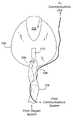
- FIG. 1illustrates a frontal view of an air mask according to some embodiments of the invention. embodiments of the invention.
- FIG. 3illustrates a functional block diagram of an oxygen partial pressure monitoring apparatus according to some embodiments of the invention
- FIG. 4illustrates a functional block diagram of another oxygen partial pressure monitoring apparatus according to some embodiments of the invention.
- FIG. 5illustrates a functional block diagram of yet another oxygen partial pressure monitoring apparatus according to some embodiments of the invention.
- FIG. 6illustrates a functional block diagram of still another oxygen partial pressure monitoring apparatus according to some embodiments of the invention.
- FIG. 7illustrates another cross-sectional side view of the air mask according to some embodiments of the invention.
- FIG. 8illustrates a circuit diagram of an oxygen partial pressure monitoring apparatus according to some embodiments of the invention.
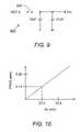
- FIG. 9illustrates a power switch for the oxygen partial pressure monitoring apparatus according to some embodiments of the invention.
- FIG. 10is a graph of oxygen partial pressure versus output voltage of an oxygen partial pressure sensor.
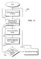
- FIG. 11is a flow chart illustrating a method of monitoring oxygen partial pressure according to some embodiments of the invention.
- Embodiments of the inventionprovide a method and apparatus for monitoring oxygen partial pressure in an air mask of an oxygen system.
- an oxygen partial pressure sensoris used to detect the oxygen partial pressure of the air flow from the oxygen system into the air mask.
- the oxygen partial pressure sensorgenerates an output signal that corresponds to the partial pressure of the oxygen in the air mask.
- the output signal from the oxygen partial pressure sensoris subsequently compared to a reference signal representing an acceptable oxygen partial pressure. If the output signal is determined to be different (e.g., lower) than the reference value or outside a predefined range of values, then the comparator causes a vibrator to vibrate the air mask, thereby alerting the user to a potentially hypoxic condition.
- Power for the oxygen partial pressure sensor and the comparatoris provided from a power source independent of the oxygen system.
- the partial pressure of oxygen in the air maskis monitored as opposed to the concentration of oxygen because the former quantity is subject to changes due to fluctuations in the total pressure.
- changes in the cabin pressureaffect the total pressure significantly and, therefore, the partial pressure of oxygen can also change significantly.
- Changes in the concentration of oxygenare also common, however, in aircrafts with diluter-regulators that mix air with oxygen as a function of altitude.
- the oxygen partial pressure P O2is the product of the total pressure P T and the concentration of oxygen Y O2 .
- measuring the oxygen partial pressure P O2can simplify the sensor design because the total pressure P T is not required to be measured, as would be the case for a sensor that measures only concentration.
- the air mask 100may be of the kind used by a pilot in an aircraft cockpit oxygen system, or it may be of the kind used by airline crew members in an emergency cabin depressurization system. Included with the air mask 100 is a nose piece 102 that fits over a user's nose in order to effect a comfortable, but snug fit.
- An air hose 104is connected to the air mask 100 and extends from an oxygen system (not expressly shown) that provides oxygen to the user.
- a communications cord 106extends from the aircraft communications system along the air hose 104 and around the air mask 100 to the communications unit (not expressly shown).
- Mounted within the air mask 100are a microphone 108 and a hypoxia warning device 110 according to some embodiments of the invention, both of which are shown here in dotted lines.
- FIG. 2A cross-sectional side view of the air mask 100 is shown in FIG. 2 , where it can be seen that the hypoxia warning device 110 is attached or otherwise mounted to an inner surface of the air mask 100 .
- Part of the communications cord 106extends into the air mask 100 to connect the microphone 108 to the communications systems. This routing of the communications cord 106 into the air mask 100 provides power for the microphone 108 and is standard for most aircraft.
- the communications cord 106is also used to provide power to the hypoxia warning device 110 .
- the hypoxia warning device 110can be connected to, and can draw power from, the same communications cord 106 that connects the microphone 108 to the communications system. This arrangement provides a convenient and easy to install power source for the hypoxia warning device 110 , and allows the hypoxia warning device 110 to operate independently of the oxygen system.
- the hypoxia warning device 110is configured to detect and monitor the oxygen partial pressure directly within the air mask 100 . By measuring the atmosphere directly within the air mask, the hypoxia warning device 110 can detect malfunctions such as a leak in the air hose connecting the oxygen system and the air mask 100 . If the oxygen partial pressure falls below a certain acceptable level, the hypoxia warning device 110 is configured to activate a vibrator that vibrates the air mask 100 , or portions thereof, to warn the user that a potentially hypoxic condition exists.
- such a tactile warning on the nose or face of the usercan be more effective than, for example, a visual or audio warning alone for alerting a user who may already be groggy, drowsy, or who may otherwise have a delayed response time due to the onset of hypoxia.
- the vibrating sensation of the air mask 100 across the user's nose and facecan irritate, aggravate, or otherwise provoke a possibly hypoxic user into prompt and immediate corrective actions.
- the vibratorcan create sufficient mechanical vibration to break the microphone VOX and produce a very loud and distinct whining tone over the aircraft audio system. This tone alerts other users, if present in a multi-crew aircraft, that a crew member is having oxygen partial pressure problems so the crew can work together to solve the problem.
- the hypoxia warning device 300includes an oxygen partial pressure sensor 302 (PPO 2 ), a current-to-voltage converter 304 , a comparator unit 306 , a vibrator 308 , and optionally, an audio or visual alarm 310 (in dashed lines), all interconnected as shown.
- the oxygen partial pressure sensor 302which may be a zirconium or a lead based electrochemical sensor, is capable of detecting the partial pressure of the oxygen in the air mask and generating an output signal that is proportional to the detected oxygen partial pressure.
- a sensoris known in the electrochemical art and may be obtained from, for example, Thermo Gas Tech, Newark, Calif.
- Electrochemical sensorshave about a year and a half of working life, so the circuitry of the hypoxia warning device 110 should be designed to allow for replacement of the sensor. Furthermore, these sensors should be protected from liquid or water that might enter from condensation of water vapor from breathing. Many of these sensors have a built-in semi-permeable membrane that prevents liquid water from entering the sensor.
- the response time of the oxygen partial pressure sensor 302is typically on the order of 10 seconds, which is desirable for some embodiments of the invention in order to avoid picking up minor fluctuations in the oxygen partial pressure and fluctuations due to breathing.
- the output signal of the oxygen partial pressure sensor 302may be an electric current Is which is received by the current-to-voltage converter 304 .
- the current-to-voltage converter 304is configured to convert the electric current Is into a corresponding voltage Vs.
- the converter 304is also configured to amplify the output voltage Vs by a predetermined factor or gain in order to provide a stronger voltage signal for stability during further processing.
- the voltage Vsis then provided to the comparator 306 , which is configured to compare the voltage Vs to a reference voltage Vref. If the output voltage Vs is about the same or higher than the reference voltage Vref, indicating normal oxygen partial pressure levels, then the output of the comparator 306 remains off. However, if the output voltage Vs falls below the reference voltage Vref, indicating potentially hypoxic conditions, then the output of the comparator 306 turns on to drive or activate the vibrator 308 .
- the reference voltage Vrefis preferably set to correspond to an acceptable or desired oxygen partial pressure.
- the normal oxygen partial pressureis about 0.20 atmospheres at sea level. To avoid hypoxia, it is recommended that the oxygen partial pressure be maintained at or above 80% of the normal value. Accordingly, the reference voltage Vref may be set to a value that corresponds to an oxygen partial pressure of about 0.16 atmospheres. However, depending on the application, other values for the reference voltage Vref may certainly be used as needed. For example, it is acceptable to fly without supplemental oxygen up to a cabin pressure equal to 10,000 feet. Thus, the low oxygen partial pressure alarm set point may be chosen to correspond to an elevation of 11,000 feet.
- the total pressureis 0.67 atmospheres (as determined from the standard atmosphere tables in the CRC Handbook of Physics), which gives 67% of the oxygen partial pressure that one receives at sea level.
- the reference voltage Vrefmay then be set to a value corresponding to an oxygen partial pressure of 0.13 atmospheres.
- the reference voltage Vrefmay be set to a predefined range of values corresponding to a desired range of oxygen partial pressures.
- the desired range of oxygen partial pressuremay be, for example, 0.20 atmospheres to some predefined upper or lower limit.
- the output of the comparator 306can be configured to remain off as long as the output voltage signal Vs stays within the predefined range of values, and to turn on only when the output voltage signal Vs falls outside the predefined range of values.
- the vibrator 308is configured to vibrate the air mask in order to warn the user of a potentially hypoxic condition.
- the vibrator 308may be a simple vibrating motor such as the kind found in a common pager. Such motors typically rotate an eccentric mass about a central axis at a speed of about 8,000 to 10,000 RPM.
- the vibrator 308generates sufficient mechanical vibrations to break the microphone VOX and produce a loud audible tone as well as the vibrations that provoke the user. Power to the vibrator 308 is provided by the output of the comparator 306 that turns the vibrator 3080 N or OFF as needed.
- the tactile warningmay be combined with a warning tone as provided by the alarm 310 .
- the same comparator output that drives the vibrator 308can be used to activate the alarm 310 to thereby produce a warning sound or tone.
- Such a warning sound or tonemay be used together with the tactile warning of the vibrator 308 to increase the effectiveness of the hypoxia warning device 300 .
- Power for the hypoxia warning device 300may be derived by tapping into the power lines of the existing communications cord 106 (see FIGS. 1 and 2 ).
- a switch 312connects the power lines from the communications cord to the hypoxia warning device and specifically to the oxygen partial pressure sensor 302 , the current-to-voltage converter 304 , and the comparator 306 .
- the switch 312is preferably a locking power switch that is configured to allow a user to selectively connect and disconnect the power to the hypoxia warning device 300 .
- the locking power switchrequires a deliberate action from the user to power off the hypoxia warning device, thus preventing an inadvertent shutdown of the warning device.
- a switch 312gives the user the ability to cut the power to the hypoxia warning device 300 in the event of a malfunction in order to turn off the vibrator 308 and/or alarm 310 .
- FIG. 4illustrates another embodiment of the hypoxia warning device.
- the hypoxia warning device 400 of FIG. 4is similar to the hypoxia warning device 300 of FIG. 3 , with the exception that the oxygen partial pressure sensor 302 outputs a voltage instead of a current.
- the current-to-voltage converter 304is not needed in this embodiment, and the output voltage Vs may be provided directly from the oxygen partial pressure sensor 302 to the comparator 306 .
- the hypoxia warning device 500includes an analog-to-digital converter 502 connected to a processor unit 504 .
- the analog-to-digital converter 502is capable of converting the analog output voltage Vs from the oxygen partial pressure sensor 302 into a digital output signal.
- a digitized output signalmay include any number of bits such as 8, 16, 32, or more bits depending on the resolution required by the particular application.
- the processor unit 504is configured to subsequently receive and compare the digitized output signal to a reference voltage.
- a memory unit 506such as a register within the processor unit 504 stores a digital reference voltage representing a desired oxygen partial pressure. If the digitized output signal is lower than the stored digital reference voltage, then the processor activates the vibrator 308 and/or the alarm 310 accordingly.
- FIG. 6Still another embodiment of the hypoxia warning device is illustrated in FIG. 6 .
- the hypoxia warning device 600 in this embodimentis similar to the hypoxia warning device in FIG. 4 , with the exception that an internal power supply 602 is included in the form of battery unit. Thus, reliance upon an external power source such as the communications cord is not needed as the hypoxia warning device in this embodiment is substantially self-contained.
- the hypoxia warning device 700is mounted to an external surface of the air mask 100 instead of on the inside surface.
- the embodimentsare otherwise similar to the embodiments of FIG. 2 except that only the oxygen partial pressure sensor 702 has been isolated from the hypoxia warning device 700 and is mounted inside the air mask.
- Such an arrangementhas an advantage in embodiments where available space inside the air mask may be limited. Also, safety with the enriched oxygen often found inside the air mask may be better maintained by these embodiments. Other arrangements and combinations may also be used, such as mounting only the vibrator to the outer surface of the air mask.
- an amplifier having a predetermined gainmay be added to any of the embodiments to boost the output signal from oxygen partial pressure sensor.
- the battery unit 602may added or removed from any of the embodiments.
- some functional componentsmay be combined with other functional components, or divided into smaller individual components. It is also possible to have an oxygen partial pressure sensor with an output inversely proportional to the partial pressure of oxygen. In such cases, the comparator should trigger the vibrator and/or alarm when the output voltage Vs rises above a preset reference value.
- the hypoxia warning devicemay be implemented using discrete circuit components such as resistors, capacitors, diodes, one or more logic gates, and the like, or using one or more semiconductor integrated circuits such as a microprocessor, DSP, ASIC, and the like. Following is a description of one exemplary implementation of a hypoxia warning device, as shown in FIG. 8 .
- a hypoxia warning device 800 in this implementationincludes an oxygen partial pressure sensor 802 which is an electrochemical battery with an output voltage that is substantially linear with the oxygen partial pressure.
- an oxygen partial pressure sensor 802which is an electrochemical battery with an output voltage that is substantially linear with the oxygen partial pressure.
- using a sensor 802 that measures oxygen partial pressureis preferred to one that measures only concentration because it is the oxygen partial pressure (which is the product of the concentration and total pressure) that is important for detecting hypoxic conditions.
- the particular oxygen partial pressure sensor 802 used in this implementationis model 165-0002 (available from Thermo Gas Tech, Newark, Calif.) that outputs 34.4 mV at 0.20 atmospheres of oxygen partial pressure and 23.0 mV at 0.13 atmospheres.
- a graph of the output voltage versus the oxygen partial pressureis shown in FIG. 10 for this model, which also has a 10 second time response so any sudden changes in oxygen partial pressure are damped.
- This sensoralso has a built-in water barrier membrane and a working life of approximately 1.5 years.
- the output voltage of the oxygen partial pressureis then provided to the positive input of the first op-amp 804 in a dual op-amp package such as a Motorola LM358 op-amp (available from Mouser Electronics, Mansfield, Tex.) with a non-inverting adjustable gain of about 100.
- the first op-amp 804is used here as an amplifier, the gain for which can be adjusted as needed by adjusting the 5K trim pot to boost the output signal from the oxygen partial pressure sensor.
- a specific low oxygen partial pressuremay be selected, below which a warning is issued according to various embodiments of the invention, indicating that a potentially hypoxic condition exists.
- the output Vs from the first op-amp 804is provide to a summing node and into the negative input of the second op-amp 806 , which is used here as an open loop comparator.
- a reference voltage of 2.500 volts (+/ ⁇ 0.025 volts)is generated by reference voltage generator such as a Motorola MC1403 (available from Mouser Electronics, Mansfield, Tex.) and provided to the positive terminal of the second op-amp 806 .
- the output of the second op-amp 806stays at a few millivolts so long as the amplified sensor voltage Vs from the first op-amp 804 stays at or above 2.500 volts.
- the vibrator 808 in this implementationis a simple 1.3 volts DC pager motor.
- a diodesuch as an IN4153 diode (available from Mouser Electronics, Mansfield, Tex.) across the vibrator 808 protects the switching transistor from possible transient inductive voltage spikes from an inductive motor load.
- a momentary double-pull double-throw (DPDT) push button switch 810is used to perform two functions. First, if the motor state is not ON for low oxygen partial pressure, depressing the push button 810 triggers the switching transistor as a circuit test to demonstrate that the vibrator has power and that vibrations can be felt. Second, if the oxygen partial pressure causes the vibrator to turn ON, cycling the push button 810 resets the vibrator 810 to the OFF state for a time determined by the RC time constant of the 10 M resistor and the 100 uF capacitor (about 30 seconds).
- a power supply circuit 900provides power Vcc to the hypoxia warning device, which power Vcc can range from +4 to +16 volts with little effect on the circuit operation.
- the power Vccis derived from the same source as the microphone power and is about +6.8 volts DC.
- Two capacitors off of the power supplyhelp to filter out low and high frequency noise that may be present in the power supply.
- a locking power switch 902is provided so the user can disconnect the power from the circuit in the event of a system failure that erroneously switches on the vibrator.
- the choice of circuit componentsshould be made so that the circuit is stable (e.g., stable op-amp gain) through fairly large temperature swings (e.g., about ⁇ 10 to +45 degrees Celsius). It is important to create an integrated design of the hypoxia warning device and the mask so that safety with the enriched oxygen often found within the mask is maintained.
- Material components on the inside of the maskshould be oxygen compatible. Some components, for example, the vibrator motor, are preferably mounted on the external mask surface. As an additional precaution, the vibrator may be potted with oxygen compatible, fire retardant resin.
- FIG. 11is a flow chart of an exemplary method 1100 for monitoring oxygen partial pressure in an air mask of an oxygen system according to some embodiments of the invention.
- the oxygen partial pressureis detected in the air mask.
- a signalis generated that corresponds to oxygen partial pressure in the air mask.
- the generated signalis then processed at step 1103 including amplification, current-to-voltage conversion, and/or analog-to-digital conversion as needed.
- the processed generated signalis compared to a predefined reference signal corresponding to a desired or acceptable oxygen partial pressure.
- a comparisonis made at step 1105 as to whether the processed generated signal is different (e.g., lower) than the reference signal or outside a predefined reference range. If yes, a warning is issued by a vibrating the air mask (via a vibrating motor) at step 1106 to alert the user of a potentially hypoxic condition. If no, the method returns to step 1101 to continue the monitoring process.
- embodiments of the inventionprovide a method and apparatus for monitoring oxygen partial pressure in an air mask of an oxygen system.
- Advantages of the inventioninclude a simple hypoxia warning device that has no connections to the oxygen system. Such a device is independent of the cockpit or cabin depressurization system of any aircraft and can thus be used with little or no aircraft modification. Also, a vibrator beating the nose and face of the user is a very effective warning for an already groggy user in an environment that is saturated with visual cues and sounds.
Landscapes
- Health & Medical Sciences (AREA)
- General Health & Medical Sciences (AREA)
- Pulmonology (AREA)
- Engineering & Computer Science (AREA)
- Public Health (AREA)
- Emergency Medicine (AREA)
- Anesthesiology (AREA)
- Biomedical Technology (AREA)
- Heart & Thoracic Surgery (AREA)
- Hematology (AREA)
- Life Sciences & Earth Sciences (AREA)
- Animal Behavior & Ethology (AREA)
- Veterinary Medicine (AREA)
- Aviation & Aerospace Engineering (AREA)
- Business, Economics & Management (AREA)
- Emergency Management (AREA)
- Respiratory Apparatuses And Protective Means (AREA)
Abstract
Description
PO2=YO2·PT (1)
Claims (8)
Priority Applications (1)
| Application Number | Priority Date | Filing Date | Title |
|---|---|---|---|
| US10/087,866US7040319B1 (en) | 2002-02-22 | 2002-02-22 | Method and apparatus for monitoring oxygen partial pressure in air masks |
Applications Claiming Priority (1)
| Application Number | Priority Date | Filing Date | Title |
|---|---|---|---|
| US10/087,866US7040319B1 (en) | 2002-02-22 | 2002-02-22 | Method and apparatus for monitoring oxygen partial pressure in air masks |
Publications (1)
| Publication Number | Publication Date |
|---|---|
| US7040319B1true US7040319B1 (en) | 2006-05-09 |
Family
ID=36272104
Family Applications (1)
| Application Number | Title | Priority Date | Filing Date |
|---|---|---|---|
| US10/087,866Expired - Fee RelatedUS7040319B1 (en) | 2002-02-22 | 2002-02-22 | Method and apparatus for monitoring oxygen partial pressure in air masks |
Country Status (1)
| Country | Link |
|---|---|
| US (1) | US7040319B1 (en) |
Cited By (39)
| Publication number | Priority date | Publication date | Assignee | Title |
|---|---|---|---|---|
| US20060266363A1 (en)* | 2005-05-31 | 2006-11-30 | Drager Safety Ag & Co. Kgaa | Breathing mask |
| US20080149186A1 (en)* | 2006-12-21 | 2008-06-26 | Martin Ricky L | Method and apparatus for emission management |
| US7422497B1 (en) | 2007-03-09 | 2008-09-09 | Brunswick Corporation | Haptic notification system for a marine vessel |
| US7481216B1 (en)* | 2004-12-28 | 2009-01-27 | Dae Systems Gmbh | Emergency oxygen system for aircraft passengers |
| US20090199857A1 (en)* | 2006-03-01 | 2009-08-13 | Resmed Limited | Method and Apparatus for Reminding user to Replace and/or Service Cpap Apparatus and/or Component Thereof |
| US20100308991A1 (en)* | 2006-02-10 | 2010-12-09 | Undersea Sensor Systems. Inc. | Communication system for heads-up display |
| WO2011104635A1 (en)* | 2010-02-26 | 2011-09-01 | Intertechnique | Method for determining partial pressure of a gaseous constituent and regulator of breathing mask for aircraft occupant |
| WO2012116764A1 (en)* | 2011-02-28 | 2012-09-07 | Intertechnique | Method for protecting aircraft occupant and breathing mask |
| USD703560S1 (en) | 2012-08-12 | 2014-04-29 | Matthew Matusik | Gas flow indicator |
| USD703558S1 (en) | 2012-08-12 | 2014-04-29 | Matthew Matusik | Housing for gas flow indicator |
| USD703561S1 (en) | 2012-08-12 | 2014-04-29 | Matthew Matusik | Gas flow indicator |
| USD703559S1 (en) | 2012-08-12 | 2014-04-29 | Matthew Matusik | Housing for gas flow indicator |
| USD708080S1 (en) | 2013-02-12 | 2014-07-01 | Matthew Matusik | Housing for gas flow indicator |
| USD712766S1 (en) | 2013-02-12 | 2014-09-09 | Matthew Matusik | Gas flow indicator |
| USD712767S1 (en) | 2013-02-12 | 2014-09-09 | Matthew Matusik | Gas flow indicator |
| USD713276S1 (en) | 2013-02-12 | 2014-09-16 | Matthew Matusik | Housing for gas flow indicator |
| US20150090257A1 (en)* | 2013-09-27 | 2015-04-02 | Honeywell International Inc. | Mask including integrated sound conduction for alert notification in high-noise environments |
| US9097657B2 (en) | 2013-07-23 | 2015-08-04 | General Electric Company | Leak detection of stator liquid cooling system |
| US9170193B2 (en) | 2013-06-06 | 2015-10-27 | General Electric Company | Detecting coolant leaks in turbine generators |
| US20170333664A1 (en)* | 2016-04-21 | 2017-11-23 | Yuanming Luo | Carbon Dioxide Inhalation Treatment Device for Central Sleep Apnea |
| WO2018017565A1 (en)* | 2016-07-22 | 2018-01-25 | Nihon Kohden America, Inc. | Masks, systems, and methods for assisting respiration including scattering chamber |
| EP3287173A1 (en)* | 2016-08-24 | 2018-02-28 | Insta ILS Oy | An apparatus and method for monitoring breathing air |
| US9913997B2 (en) | 2013-07-23 | 2018-03-13 | Lockheed Martin Corporation | Respiratory gas monitoring |
| US20180131265A1 (en)* | 2011-07-11 | 2018-05-10 | Model Software Corporation | Methods for minimizing delayed effects of exposure to reduced oxygen partial pressure via administration of supplemental oxygen |
| US20180193584A1 (en)* | 2017-01-11 | 2018-07-12 | Model Software Corporation | Methods for minimizing delayed effects of exposure to reduced oxygen partial pressure via administration of supplemental oxygen |
| US20180303392A1 (en)* | 2017-04-20 | 2018-10-25 | Gmeci, Llc | Human performance oxygen sensor |
| US10307558B2 (en) | 2016-12-29 | 2019-06-04 | Vpas Group Pty Ltd | Gas flow indicator device |
| US10314988B2 (en) | 2012-08-12 | 2019-06-11 | Vpas Group Pty Ltd | Gas flow indicator |
| US10532175B1 (en) | 2019-05-23 | 2020-01-14 | Model Software Corporation | Methods for minimizing delayed effects of exposure to reduced oxygen partial pressure via administration of supplemental oxygen |
| US10701470B2 (en) | 2017-09-07 | 2020-06-30 | Light Speed Aviation, Inc. | Circumaural headset or headphones with adjustable biometric sensor |
| US10764668B2 (en) | 2017-09-07 | 2020-09-01 | Lightspeed Aviation, Inc. | Sensor mount and circumaural headset or headphones with adjustable sensor |
| US11067551B2 (en)* | 2017-01-09 | 2021-07-20 | Zodiac Aerotechnics | Device for measuring the amount of oxygen present in a gas, and air-separation module comprising such a measurement device |
| WO2021248009A1 (en)* | 2020-06-04 | 2021-12-09 | University Of Cincinnati | Feedback providing facial masks |
| US11389604B2 (en) | 2017-06-28 | 2022-07-19 | Vpas Group Pty Ltd | Gas flow indicator device |
| CN115518311A (en)* | 2022-06-09 | 2022-12-27 | 韩玉凤 | Ore tunnel is with apparatus of oxygen supply that has oxygen concentration detection function |
| US11617847B2 (en) | 2017-01-11 | 2023-04-04 | Model Software Corporation | Methods for minimizing delayed effects of exposure to reduced oxygen partial pressure via administration of supplemental oxygen |
| US12029564B2 (en) | 2017-04-20 | 2024-07-09 | Gmeci, Llc | Human performance oxygen sensor and headset |
| US12274545B2 (en)* | 2022-04-28 | 2025-04-15 | Gmeci, Llc | Methods and systems for detection of atelectasis in flight |
| US12418613B2 (en) | 2022-11-30 | 2025-09-16 | Gmeci, Llc | Apparatus and methods for monitoring human trustworthiness |
Citations (24)
| Publication number | Priority date | Publication date | Assignee | Title |
|---|---|---|---|---|
| US2798588A (en)* | 1954-09-16 | 1957-07-09 | Wolfe Baron C | Log decking machine |
| US3672388A (en)* | 1969-06-19 | 1972-06-27 | Gen Electric | Sensor and control system for controlling gas partial pressure |
| US3675649A (en)* | 1970-08-21 | 1972-07-11 | Westland Aircraft Ltd | Electronically controlled oxygen regulators |
| US4335735A (en)* | 1980-09-22 | 1982-06-22 | The Bendix Corporation | Automatic diluter/demand oxygen regulator adapted for chemical or biological use |
| US4373521A (en)* | 1981-08-24 | 1983-02-15 | The United States Of America As Represented By The Secretary Of The Navy | Heated breathing bag sheath |
| US4423723A (en)* | 1981-03-13 | 1984-01-03 | Dragerwerk Aktiengesellschaft | Closed cycle respirator with emergency oxygen supply |
| US4440166A (en)* | 1981-03-13 | 1984-04-03 | Dragerwerk Aktiengesellschaft | Electrically and mechanically controllable closed cycle respirator |
| US4906990A (en)* | 1989-02-21 | 1990-03-06 | The Boeing Company | Anti-G system failure detection |
| US4928682A (en)* | 1987-10-14 | 1990-05-29 | Normalair-Garrett (Holdings) Limited | Aircraft on-board oxygen generating systems |
| US4939647A (en)* | 1987-07-03 | 1990-07-03 | Carmellan Research Limited | Re-breather diving unit with oxygen adjustment for decompression optimization |
| US4960119A (en)* | 1988-05-31 | 1990-10-02 | Normalair-Garrett (Holdings) Limited | Aircraft aircrew life support systems |
| USH1039H (en)* | 1988-11-14 | 1992-04-07 | The United States Of America As Represented By The Secretary Of The Air Force | Intrusion-free physiological condition monitoring |
| US5445160A (en)* | 1991-05-08 | 1995-08-29 | Nellcor Incorporated | Portable carbon dioxide monitor |
| US5503145A (en)* | 1992-06-19 | 1996-04-02 | Clough; Stuart | Computer-controlling life support system and method for mixed-gas diving |
| US5659296A (en)* | 1994-10-24 | 1997-08-19 | Minnesota Mining And Manufacturing Company | Exposure indicating apparatus |
| US5666949A (en)* | 1994-10-24 | 1997-09-16 | Minnesota Mining And Manufacturing Company | Exposure indicator with continuous alarm signal indicating multiple conditions |
| US6091974A (en)* | 1994-06-27 | 2000-07-18 | Carmel Biosensors Ltd | Implantable capsule for enhancing cell electric signals |
| US6165105A (en)* | 1996-09-27 | 2000-12-26 | Boutellier; Urs | Apparatus and method for training of the respiratory muscles |
| US6199550B1 (en)* | 1998-08-14 | 2001-03-13 | Bioasyst, L.L.C. | Integrated physiologic sensor system |
| US6239724B1 (en)* | 1997-12-30 | 2001-05-29 | Remon Medical Technologies, Ltd. | System and method for telemetrically providing intrabody spatial position |
| US6289238B1 (en)* | 1993-09-04 | 2001-09-11 | Motorola, Inc. | Wireless medical diagnosis and monitoring equipment |
| US6289890B1 (en)* | 1998-03-20 | 2001-09-18 | Valley Inspired Products, Llc | Portable rescue breathing device |
| US6401714B1 (en)* | 1997-04-03 | 2002-06-11 | Scott Technologies, Inc. | Self contained breathing apparatus |
| US6429558B1 (en)* | 1998-09-24 | 2002-08-06 | Namiki Seimitsu Houseki Kabushiki Kaisha | Small-sized coreless motor |
- 2002
- 2002-02-22USUS10/087,866patent/US7040319B1/ennot_activeExpired - Fee Related
Patent Citations (24)
| Publication number | Priority date | Publication date | Assignee | Title |
|---|---|---|---|---|
| US2798588A (en)* | 1954-09-16 | 1957-07-09 | Wolfe Baron C | Log decking machine |
| US3672388A (en)* | 1969-06-19 | 1972-06-27 | Gen Electric | Sensor and control system for controlling gas partial pressure |
| US3675649A (en)* | 1970-08-21 | 1972-07-11 | Westland Aircraft Ltd | Electronically controlled oxygen regulators |
| US4335735A (en)* | 1980-09-22 | 1982-06-22 | The Bendix Corporation | Automatic diluter/demand oxygen regulator adapted for chemical or biological use |
| US4423723A (en)* | 1981-03-13 | 1984-01-03 | Dragerwerk Aktiengesellschaft | Closed cycle respirator with emergency oxygen supply |
| US4440166A (en)* | 1981-03-13 | 1984-04-03 | Dragerwerk Aktiengesellschaft | Electrically and mechanically controllable closed cycle respirator |
| US4373521A (en)* | 1981-08-24 | 1983-02-15 | The United States Of America As Represented By The Secretary Of The Navy | Heated breathing bag sheath |
| US4939647A (en)* | 1987-07-03 | 1990-07-03 | Carmellan Research Limited | Re-breather diving unit with oxygen adjustment for decompression optimization |
| US4928682A (en)* | 1987-10-14 | 1990-05-29 | Normalair-Garrett (Holdings) Limited | Aircraft on-board oxygen generating systems |
| US4960119A (en)* | 1988-05-31 | 1990-10-02 | Normalair-Garrett (Holdings) Limited | Aircraft aircrew life support systems |
| USH1039H (en)* | 1988-11-14 | 1992-04-07 | The United States Of America As Represented By The Secretary Of The Air Force | Intrusion-free physiological condition monitoring |
| US4906990A (en)* | 1989-02-21 | 1990-03-06 | The Boeing Company | Anti-G system failure detection |
| US5445160A (en)* | 1991-05-08 | 1995-08-29 | Nellcor Incorporated | Portable carbon dioxide monitor |
| US5503145A (en)* | 1992-06-19 | 1996-04-02 | Clough; Stuart | Computer-controlling life support system and method for mixed-gas diving |
| US6289238B1 (en)* | 1993-09-04 | 2001-09-11 | Motorola, Inc. | Wireless medical diagnosis and monitoring equipment |
| US6091974A (en)* | 1994-06-27 | 2000-07-18 | Carmel Biosensors Ltd | Implantable capsule for enhancing cell electric signals |
| US5659296A (en)* | 1994-10-24 | 1997-08-19 | Minnesota Mining And Manufacturing Company | Exposure indicating apparatus |
| US5666949A (en)* | 1994-10-24 | 1997-09-16 | Minnesota Mining And Manufacturing Company | Exposure indicator with continuous alarm signal indicating multiple conditions |
| US6165105A (en)* | 1996-09-27 | 2000-12-26 | Boutellier; Urs | Apparatus and method for training of the respiratory muscles |
| US6401714B1 (en)* | 1997-04-03 | 2002-06-11 | Scott Technologies, Inc. | Self contained breathing apparatus |
| US6239724B1 (en)* | 1997-12-30 | 2001-05-29 | Remon Medical Technologies, Ltd. | System and method for telemetrically providing intrabody spatial position |
| US6289890B1 (en)* | 1998-03-20 | 2001-09-18 | Valley Inspired Products, Llc | Portable rescue breathing device |
| US6199550B1 (en)* | 1998-08-14 | 2001-03-13 | Bioasyst, L.L.C. | Integrated physiologic sensor system |
| US6429558B1 (en)* | 1998-09-24 | 2002-08-06 | Namiki Seimitsu Houseki Kabushiki Kaisha | Small-sized coreless motor |
Cited By (50)
| Publication number | Priority date | Publication date | Assignee | Title |
|---|---|---|---|---|
| US7481216B1 (en)* | 2004-12-28 | 2009-01-27 | Dae Systems Gmbh | Emergency oxygen system for aircraft passengers |
| US20060266363A1 (en)* | 2005-05-31 | 2006-11-30 | Drager Safety Ag & Co. Kgaa | Breathing mask |
| US7770581B2 (en)* | 2005-05-31 | 2010-08-10 | Dräger Safety AG & Co. KGaA | Breathing mask |
| US20100308991A1 (en)* | 2006-02-10 | 2010-12-09 | Undersea Sensor Systems. Inc. | Communication system for heads-up display |
| US20090199857A1 (en)* | 2006-03-01 | 2009-08-13 | Resmed Limited | Method and Apparatus for Reminding user to Replace and/or Service Cpap Apparatus and/or Component Thereof |
| US20080149186A1 (en)* | 2006-12-21 | 2008-06-26 | Martin Ricky L | Method and apparatus for emission management |
| US7422497B1 (en) | 2007-03-09 | 2008-09-09 | Brunswick Corporation | Haptic notification system for a marine vessel |
| WO2011104635A1 (en)* | 2010-02-26 | 2011-09-01 | Intertechnique | Method for determining partial pressure of a gaseous constituent and regulator of breathing mask for aircraft occupant |
| CN102858408A (en)* | 2010-02-26 | 2013-01-02 | 联合技术公司 | Method for determining partial pressures of gas components and regulators for breathing masks for aircraft occupants |
| CN102858408B (en)* | 2010-02-26 | 2015-01-28 | 联合技术公司 | Method for determining partial pressures of gas components and regulators for breathing masks for aircraft occupants |
| US9808655B2 (en) | 2010-02-26 | 2017-11-07 | Zodiac Aerotechnics | Method for determining partial pressure of a gaseous constituent and regulator of breathing mask for aircraft occupant |
| WO2012116764A1 (en)* | 2011-02-28 | 2012-09-07 | Intertechnique | Method for protecting aircraft occupant and breathing mask |
| CN103476461A (en)* | 2011-02-28 | 2013-12-25 | 联合技术公司 | Method for protecting aircraft occupant and breathing mask |
| US20180131265A1 (en)* | 2011-07-11 | 2018-05-10 | Model Software Corporation | Methods for minimizing delayed effects of exposure to reduced oxygen partial pressure via administration of supplemental oxygen |
| USD703561S1 (en) | 2012-08-12 | 2014-04-29 | Matthew Matusik | Gas flow indicator |
| USD703558S1 (en) | 2012-08-12 | 2014-04-29 | Matthew Matusik | Housing for gas flow indicator |
| US10314988B2 (en) | 2012-08-12 | 2019-06-11 | Vpas Group Pty Ltd | Gas flow indicator |
| USD703560S1 (en) | 2012-08-12 | 2014-04-29 | Matthew Matusik | Gas flow indicator |
| USD703559S1 (en) | 2012-08-12 | 2014-04-29 | Matthew Matusik | Housing for gas flow indicator |
| USD712767S1 (en) | 2013-02-12 | 2014-09-09 | Matthew Matusik | Gas flow indicator |
| USD713276S1 (en) | 2013-02-12 | 2014-09-16 | Matthew Matusik | Housing for gas flow indicator |
| USD712766S1 (en) | 2013-02-12 | 2014-09-09 | Matthew Matusik | Gas flow indicator |
| USD708080S1 (en) | 2013-02-12 | 2014-07-01 | Matthew Matusik | Housing for gas flow indicator |
| US9170193B2 (en) | 2013-06-06 | 2015-10-27 | General Electric Company | Detecting coolant leaks in turbine generators |
| US9097657B2 (en) | 2013-07-23 | 2015-08-04 | General Electric Company | Leak detection of stator liquid cooling system |
| US9913997B2 (en) | 2013-07-23 | 2018-03-13 | Lockheed Martin Corporation | Respiratory gas monitoring |
| US20150090257A1 (en)* | 2013-09-27 | 2015-04-02 | Honeywell International Inc. | Mask including integrated sound conduction for alert notification in high-noise environments |
| US10065055B2 (en)* | 2013-09-27 | 2018-09-04 | Honeywell International Inc. | Mask including integrated sound conduction for alert notification in high-noise environments |
| US20170333664A1 (en)* | 2016-04-21 | 2017-11-23 | Yuanming Luo | Carbon Dioxide Inhalation Treatment Device for Central Sleep Apnea |
| US10898669B2 (en)* | 2016-04-21 | 2021-01-26 | Yuanming Luo | Carbon dioxide inhalation treatment device for central sleep apnea |
| US11253666B2 (en) | 2016-07-22 | 2022-02-22 | Nihon Kohden America, Inc. | Masks, systems, and methods for assisting respiration including scattering chamber |
| WO2018017565A1 (en)* | 2016-07-22 | 2018-01-25 | Nihon Kohden America, Inc. | Masks, systems, and methods for assisting respiration including scattering chamber |
| EP3287173A1 (en)* | 2016-08-24 | 2018-02-28 | Insta ILS Oy | An apparatus and method for monitoring breathing air |
| US11033762B2 (en) | 2016-08-24 | 2021-06-15 | Insta Ils Oy | Apparatus and method for monitoring breathing air |
| US10307558B2 (en) | 2016-12-29 | 2019-06-04 | Vpas Group Pty Ltd | Gas flow indicator device |
| US11067551B2 (en)* | 2017-01-09 | 2021-07-20 | Zodiac Aerotechnics | Device for measuring the amount of oxygen present in a gas, and air-separation module comprising such a measurement device |
| US20180193584A1 (en)* | 2017-01-11 | 2018-07-12 | Model Software Corporation | Methods for minimizing delayed effects of exposure to reduced oxygen partial pressure via administration of supplemental oxygen |
| US11617847B2 (en) | 2017-01-11 | 2023-04-04 | Model Software Corporation | Methods for minimizing delayed effects of exposure to reduced oxygen partial pressure via administration of supplemental oxygen |
| US10667731B2 (en)* | 2017-04-20 | 2020-06-02 | Gmeci, Llc | Human performance oxygen sensor |
| US12029564B2 (en) | 2017-04-20 | 2024-07-09 | Gmeci, Llc | Human performance oxygen sensor and headset |
| US20180303392A1 (en)* | 2017-04-20 | 2018-10-25 | Gmeci, Llc | Human performance oxygen sensor |
| US11389604B2 (en) | 2017-06-28 | 2022-07-19 | Vpas Group Pty Ltd | Gas flow indicator device |
| US10701470B2 (en) | 2017-09-07 | 2020-06-30 | Light Speed Aviation, Inc. | Circumaural headset or headphones with adjustable biometric sensor |
| US10764668B2 (en) | 2017-09-07 | 2020-09-01 | Lightspeed Aviation, Inc. | Sensor mount and circumaural headset or headphones with adjustable sensor |
| US10532175B1 (en) | 2019-05-23 | 2020-01-14 | Model Software Corporation | Methods for minimizing delayed effects of exposure to reduced oxygen partial pressure via administration of supplemental oxygen |
| WO2021248009A1 (en)* | 2020-06-04 | 2021-12-09 | University Of Cincinnati | Feedback providing facial masks |
| US12274545B2 (en)* | 2022-04-28 | 2025-04-15 | Gmeci, Llc | Methods and systems for detection of atelectasis in flight |
| CN115518311A (en)* | 2022-06-09 | 2022-12-27 | 韩玉凤 | Ore tunnel is with apparatus of oxygen supply that has oxygen concentration detection function |
| CN115518311B (en)* | 2022-06-09 | 2023-10-10 | 重庆丰瀚建设工程有限公司 | Oxygen supply device with oxygen concentration detection function for ore tunnel |
| US12418613B2 (en) | 2022-11-30 | 2025-09-16 | Gmeci, Llc | Apparatus and methods for monitoring human trustworthiness |
Similar Documents
| Publication | Publication Date | Title |
|---|---|---|
| US7040319B1 (en) | Method and apparatus for monitoring oxygen partial pressure in air masks | |
| US6452510B1 (en) | Personal cabin pressure monitor and warning system | |
| EP0886537B1 (en) | Method and system for checking the operability of a breathing equipment | |
| US5200736A (en) | Assembly for monitoring helmet thermal conditions | |
| US5942979A (en) | On guard vehicle safety warning system | |
| RU2719814C1 (en) | Indication of hazardous external action in respiratory system with air supply | |
| AU2017219052B2 (en) | An apparatus and method for monitoring breathing air | |
| US5317305A (en) | Personal alarm device with vibrating accelerometer motion detector and planar piezoelectric hi-level sound generator | |
| US8390463B2 (en) | Emergency signal bracelet | |
| US11865377B2 (en) | System and method for fit test and monitoring for respiratory products | |
| US10431072B2 (en) | Fall detection alert/alarm device and method | |
| US4110741A (en) | Device for monitoring physical activity of persons | |
| JP2018089158A (en) | Respiratory protection device | |
| US20140184407A1 (en) | Wearable low pressure warning device with audio and visual indication | |
| CN113015562B (en) | SCBA mask assembly with accelerometer to extend battery life of electronics | |
| US3727626A (en) | Apparatus for controlling environmental conditions, especially suitable for use underwater | |
| KR20180020606A (en) | Air breathing apparatus with safety alarm function | |
| US9561460B2 (en) | Rescue terminal and system | |
| US9044625B2 (en) | Piezo driver having low current quiesent operation for use in a personal alert safety system of a self-contained breathing apparatus | |
| AU7268200A (en) | Warning device for a compressed air breathing apparatus | |
| US20040242981A1 (en) | Method and apparatus for increasing aircraft safety | |
| US5365923A (en) | Sound responsive optical warning apparatus and method for SCBA | |
| GB2523146A (en) | Monitoring apparatus | |
| US20200353194A1 (en) | Breathing air supply system with contactless vital parameter sensor measuring | |
| US20080303644A1 (en) | Sounder Assembly for a personal alert safety system |
Legal Events
| Date | Code | Title | Description |
|---|---|---|---|
| AS | Assignment | Owner name:U.S. GOVERNMENT AS REPRESENTED BY THE ADMINSTRATOR Free format text:ASSIGNMENT OF ASSIGNORS INTEREST;ASSIGNORS:KELLY, MARK E.;PETTIT, DONALD R.;REEL/FRAME:012904/0021;SIGNING DATES FROM 20020405 TO 20020419 | |
| FPAY | Fee payment | Year of fee payment:4 | |
| FEPP | Fee payment procedure | Free format text:PETITION RELATED TO MAINTENANCE FEES FILED (ORIGINAL EVENT CODE: PMFP); ENTITY STATUS OF PATENT OWNER: LARGE ENTITY Free format text:PETITION RELATED TO MAINTENANCE FEES GRANTED (ORIGINAL EVENT CODE: PMFG); ENTITY STATUS OF PATENT OWNER: LARGE ENTITY | |
| REMI | Maintenance fee reminder mailed | ||
| PRDP | Patent reinstated due to the acceptance of a late maintenance fee | Effective date:20140528 | |
| FPAY | Fee payment | Year of fee payment:8 | |
| SULP | Surcharge for late payment | ||
| FEPP | Fee payment procedure | Free format text:MAINTENANCE FEE REMINDER MAILED (ORIGINAL EVENT CODE: REM.) | |
| LAPS | Lapse for failure to pay maintenance fees | Free format text:PATENT EXPIRED FOR FAILURE TO PAY MAINTENANCE FEES (ORIGINAL EVENT CODE: EXP.) | |
| STCH | Information on status: patent discontinuation | Free format text:PATENT EXPIRED DUE TO NONPAYMENT OF MAINTENANCE FEES UNDER 37 CFR 1.362 | |
| FP | Lapsed due to failure to pay maintenance fee | Effective date:20180509 |