US7040166B2 - Multiple output inertial sensing device - Google Patents
Multiple output inertial sensing deviceDownload PDFInfo
- Publication number
- US7040166B2 US7040166B2US11/105,146US10514605AUS7040166B2US 7040166 B2US7040166 B2US 7040166B2US 10514605 AUS10514605 AUS 10514605AUS 7040166 B2US7040166 B2US 7040166B2
- Authority
- US
- United States
- Prior art keywords
- signal conditioning
- conditioning circuits
- linear acceleration
- change
- signal
- Prior art date
- Legal status (The legal status is an assumption and is not a legal conclusion. Google has not performed a legal analysis and makes no representation as to the accuracy of the status listed.)
- Expired - Lifetime
Links
- 230000003750conditioning effectEffects0.000claimsabstractdescription68
- XUIMIQQOPSSXEZ-UHFFFAOYSA-NSiliconChemical compound[Si]XUIMIQQOPSSXEZ-UHFFFAOYSA-N0.000claimsabstractdescription29
- 229910052710siliconInorganic materials0.000claimsabstractdescription28
- 239000010703siliconSubstances0.000claimsabstractdescription28
- 230000001133accelerationEffects0.000claimsdescription52
- 230000008859changeEffects0.000claimsdescription25
- 238000000034methodMethods0.000description10
- 238000004519manufacturing processMethods0.000description8
- 238000010586diagramMethods0.000description7
- 230000033001locomotionEffects0.000description7
- 239000004065semiconductorSubstances0.000description7
- 230000009118appropriate responseEffects0.000description5
- 230000008569processEffects0.000description5
- 238000005259measurementMethods0.000description4
- 238000006243chemical reactionMethods0.000description3
- 238000006073displacement reactionMethods0.000description3
- 238000011161developmentMethods0.000description2
- 230000018109developmental processEffects0.000description2
- 238000004806packaging method and processMethods0.000description2
- 230000004044responseEffects0.000description2
- 208000032366OversensingDiseases0.000description1
- 230000002411adverseEffects0.000description1
- 238000001514detection methodMethods0.000description1
- 230000005484gravityEffects0.000description1
- 238000009434installationMethods0.000description1
- 230000010354integrationEffects0.000description1
- 239000000463materialSubstances0.000description1
- 230000003071parasitic effectEffects0.000description1
- 230000035945sensitivityEffects0.000description1
- 230000035939shockEffects0.000description1
- 230000000153supplemental effectEffects0.000description1
Images


Classifications
- G—PHYSICS
- G01—MEASURING; TESTING
- G01C—MEASURING DISTANCES, LEVELS OR BEARINGS; SURVEYING; NAVIGATION; GYROSCOPIC INSTRUMENTS; PHOTOGRAMMETRY OR VIDEOGRAMMETRY
- G01C21/00—Navigation; Navigational instruments not provided for in groups G01C1/00 - G01C19/00
- G01C21/10—Navigation; Navigational instruments not provided for in groups G01C1/00 - G01C19/00 by using measurements of speed or acceleration
- G01C21/12—Navigation; Navigational instruments not provided for in groups G01C1/00 - G01C19/00 by using measurements of speed or acceleration executed aboard the object being navigated; Dead reckoning
- G01C21/16—Navigation; Navigational instruments not provided for in groups G01C1/00 - G01C19/00 by using measurements of speed or acceleration executed aboard the object being navigated; Dead reckoning by integrating acceleration or speed, i.e. inertial navigation
- G01C21/166—Mechanical, construction or arrangement details of inertial navigation systems
- B—PERFORMING OPERATIONS; TRANSPORTING
- B60—VEHICLES IN GENERAL
- B60R—VEHICLES, VEHICLE FITTINGS, OR VEHICLE PARTS, NOT OTHERWISE PROVIDED FOR
- B60R21/00—Arrangements or fittings on vehicles for protecting or preventing injuries to occupants or pedestrians in case of accidents or other traffic risks
- B60R21/01—Electrical circuits for triggering passive safety arrangements, e.g. airbags, safety belt tighteners, in case of vehicle accidents or impending vehicle accidents
- B60R21/013—Electrical circuits for triggering passive safety arrangements, e.g. airbags, safety belt tighteners, in case of vehicle accidents or impending vehicle accidents including means for detecting collisions, impending collisions or roll-over
- B60R21/0132—Electrical circuits for triggering passive safety arrangements, e.g. airbags, safety belt tighteners, in case of vehicle accidents or impending vehicle accidents including means for detecting collisions, impending collisions or roll-over responsive to vehicle motion parameters, e.g. to vehicle longitudinal or transversal deceleration or speed value
- G—PHYSICS
- G01—MEASURING; TESTING
- G01P—MEASURING LINEAR OR ANGULAR SPEED, ACCELERATION, DECELERATION, OR SHOCK; INDICATING PRESENCE, ABSENCE, OR DIRECTION, OF MOVEMENT
- G01P15/00—Measuring acceleration; Measuring deceleration; Measuring shock, i.e. sudden change of acceleration
- G01P15/02—Measuring acceleration; Measuring deceleration; Measuring shock, i.e. sudden change of acceleration by making use of inertia forces using solid seismic masses
- G01P15/08—Measuring acceleration; Measuring deceleration; Measuring shock, i.e. sudden change of acceleration by making use of inertia forces using solid seismic masses with conversion into electric or magnetic values
- B—PERFORMING OPERATIONS; TRANSPORTING
- B60—VEHICLES IN GENERAL
- B60R—VEHICLES, VEHICLE FITTINGS, OR VEHICLE PARTS, NOT OTHERWISE PROVIDED FOR
- B60R21/00—Arrangements or fittings on vehicles for protecting or preventing injuries to occupants or pedestrians in case of accidents or other traffic risks
- B60R21/01—Electrical circuits for triggering passive safety arrangements, e.g. airbags, safety belt tighteners, in case of vehicle accidents or impending vehicle accidents
- B60R21/013—Electrical circuits for triggering passive safety arrangements, e.g. airbags, safety belt tighteners, in case of vehicle accidents or impending vehicle accidents including means for detecting collisions, impending collisions or roll-over
- B60R21/0132—Electrical circuits for triggering passive safety arrangements, e.g. airbags, safety belt tighteners, in case of vehicle accidents or impending vehicle accidents including means for detecting collisions, impending collisions or roll-over responsive to vehicle motion parameters, e.g. to vehicle longitudinal or transversal deceleration or speed value
- B60R2021/01325—Vertical acceleration
- B—PERFORMING OPERATIONS; TRANSPORTING
- B60—VEHICLES IN GENERAL
- B60R—VEHICLES, VEHICLE FITTINGS, OR VEHICLE PARTS, NOT OTHERWISE PROVIDED FOR
- B60R21/00—Arrangements or fittings on vehicles for protecting or preventing injuries to occupants or pedestrians in case of accidents or other traffic risks
- B60R21/01—Electrical circuits for triggering passive safety arrangements, e.g. airbags, safety belt tighteners, in case of vehicle accidents or impending vehicle accidents
- B60R21/013—Electrical circuits for triggering passive safety arrangements, e.g. airbags, safety belt tighteners, in case of vehicle accidents or impending vehicle accidents including means for detecting collisions, impending collisions or roll-over
- B60R21/0132—Electrical circuits for triggering passive safety arrangements, e.g. airbags, safety belt tighteners, in case of vehicle accidents or impending vehicle accidents including means for detecting collisions, impending collisions or roll-over responsive to vehicle motion parameters, e.g. to vehicle longitudinal or transversal deceleration or speed value
- B60R2021/01327—Angular velocity or angular acceleration
Definitions
- the present inventionrelates generally to inertial sensors and, in particular, to a multiple output inertial sensing devices, which can ideally be used for motor vehicle safety systems.
- Accelerometersare well known devices that sense acceleration generated from an external source such as a body to which they are attached. Accelerometers typically contain three main components. A first component is a mass, known in the art as a seismic mass or proof mass, that moves in response to the external body's acceleration. The proof mass is held in a rest position by a second component, which is a spring or a member that functions as a spring. A displacement transducer that measures the motion of the proof mass in response to acceleration is the third component. Upon acceleration, the mass moves from its rest position, either compressing or stretching the spring. The transducer detects the movement of the mass and converts the movement into an electrical output signal.
- a first componentis a mass, known in the art as a seismic mass or proof mass, that moves in response to the external body's acceleration. The proof mass is held in a rest position by a second component, which is a spring or a member that functions as a spring.
- a displacement transducerthat measures the motion of the proof mass in response to acceleration is the
- the output signalwhich may be amplified and filtered by signal conditioning electronics for more accurate measurement, is then transmitted to a control circuit or a control device that responds to the detected acceleration.
- the springusually restricts the proof mass to movement in a single direction or axis. Accordingly, the accelerometer provides a directional acceleration signal.
- the three components of the accelerometer, the proof mass, the spring, and the transducer,are collectively known as a sensor or sense element.
- Accelerometerstypically utilize either a piezoelectric displacement transducer or a capacitive transducer.
- piezoelectric displacement transducersthe motion of the proof mass is converted into the electrical output signal by the change in resistance of a piezoresistive material as it is expands or contracts.
- Piezoelectric transducershave the disadvantage of being sensitive to heat and stress, which generally requires the use of expensive compensating electronic circuits.
- capacitive transducersthe motion of the proof mass is converted by having the motion alter the capacitance of a member, which is then measured.
- capacitive transducersalso have limitations, such as parasitic capacitance of their associated conditioning electronics, they are preferred because they are relatively unaffected by temperature and may be readily measured electronically.
- Accelerometershave been used in many different applications, including vibration measurement, for example of rotating equipment, as well as shock measurement, inertial navigation systems and motor vehicle control systems.
- Conventional accelerometerssuch as those disclosed in U.S. Pat. No. 4,945,765, are physically large and relatively expensive to produce. As a result, few conventional accelerometers have been installed on motor vehicles because of their size, weight, and cost.
- semiconductor accelerometershave been developed that include the sense elements described above that are reduced in size and are mounted on a silicon chip. As a result semiconductor accelerometers are much smaller than conventional accelerometers and thus design options regarding the location of the accelerometer are more flexible. In addition, semiconductor accelerometers are less expensive to produce than the conventional accelerometers noted above.
- Semiconductor accelerometersare typically manufactured utilizing either a bulk manufacturing technique or a surface manufacturing technique, both of which are well known in the art. Both bulk and surface manufacturing techniques are classified as Micromachined ElectroMechanical Systems (MEMS.)
- MEMSMicromachined ElectroMechanical Systems
- the transducer and associated electronicsare typically located external to the silicon chip.
- the transducer and electronicscan be mounted on the silicon chip, further reducing the accelerometer's size requirements.
- accelerometersin motor vehicles, therefore, is becoming more prevalent. They have been used in modern automobile safety systems to sense changes in acceleration and provide a control signal for vehicle control systems, including speed control systems and antilock braking systems. They have also been used to sense crash conditions in order to provide a signal to trigger the release of vehicle supplemental restraint systems, more commonly known as airbags. Accelerometers in vehicle safety systems are typically calibrated to measure the changes in acceleration in terms of G-forces.
- Gis equal to the acceleration of gravity (9.8 m/s 2 or 32.2 ft/s 2 .) Accelerometers utilized in vehicle control systems typically provide signals for “low” sensed accelerations in the range of 1.5 G while accelerometers utilized in crash sensing systems typically provide signals for “high” sensed accelerations in the range of 40 G.
- motor vehicle control systemsIn addition to sensing changes in lateral acceleration, motor vehicle control systems also utilize angular rate sensors to sense changes in angular velocity. Although angular rate sensors typically measure the change in rotational velocity of a vibrating ring rather than the change in acceleration of a proof mass, angular rate sensors also include transducers and are mounted upon silicon chips. Similar to accelerometers, angular rate sensors are utilized to supply control signals to vehicle control systems, such as, roll control systems and rollover sensing systems. Again, as with the lateral accelerometer described above, the vehicle control systems that utilize angular rate sensors can require different trigger levels. Thus, a roll control system responds to signals have smaller magnitudes than those utilized by a roll over sensing system. Angular rate sensors and accelerometers are known collectively hereinafter as inertial sensors.
- Prior art motor vehicle safety systemsthat utilized semiconductor inertial sensors typically utilized a separate semiconductor inertial sensor for each control system. Each inertial sensor in turn required a separate Application Specific Integrated Circuit (ASIC) to process the sensor signal. Separate inertial sensors increased the overall cost of each system because each ASIC and inertial sensor had to be purchased individually. Each inertial sensor and ASIC required a fixed amount of space for installation, which correspondingly increased the size and reduced the design flexibility of the various control or safety systems due to the bulkiness of the inertial sensors.
- ASICApplication Specific Integrated Circuit
- the present inventioncontemplates a single inertial sensor that provides multiple output signals for different ranges of operation.
- the inertial sensorincludes a silicon wafer that carries a plurality of inertia sense elements. Each sense element is calibrated to sense a change in acceleration or a change in angular velocity for a predetermined range.
- a low-G sense elementcan be provided for a vehicle directional control system, while a high-G sense element can be provided for vehicle crash sensing.
- a low range angular rate sensorcan be provided for a roll control system while a high range angular rate sensor can be provided for a rollover detection system.
- Each of the sense elementsis electrically connected to either a common signal conditioning circuit or a corresponding separate signal conditioning circuit.
- the signal conditioning circuitamplifies and filters the output signal from each of the sense elements and generates an enhanced output signal for each of the sense elements.
- the output signalsare transmitted to associated control systems.
- the inventioncontemplates a single sense element carried by a silicon wafer.
- the output of the single elementis electrically connected to multiple signal conditioning circuits with different sensitivities that convert the signal generated by the sense element into output signals in different ranges.
- the present inventionalso contemplates multiple inertial sensors carried by a single wafer that sense changes in inertia along or about more that one vehicle axis.
- the size requirements for the inertial sensors and associated circuit boardsare significantly reduced with a corresponding increase in packaging flexibility.
- FIG. 1is a schematic diagram of an inertial sensor in accordance with the present invention.
- FIG. 2is a schematic diagram of an alternative embodiment of the inertial sensor shown in FIG. 1 .
- FIG. 3is a schematic diagram of another alternative embodiment of the inertial sensor shown in FIG. 1 .
- FIG. 4is a schematic diagram of another alternative embodiment of the inertial sensor shown in FIG. 1 .
- FIG. 5is a schematic diagram of another alternative embodiment of the inertial sensor shown in FIG. 1 .
- FIG. 6is a schematic diagram of another alternate embodiment of the inertial sensor shown in FIG. 1 .
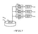
- FIG. 7is a schematic diagram of another alternate embodiment of the inertial sensor shown in FIG. 2 .
- the sensor 2contains a silicon wafer 4 .
- the sense elements 6 and 8may be lateral acceleration sense elements (accelerometers) or angular rate sense elements.
- the sense elements 6 and 8may contain one proof mass (not shown) and two transducers (not shown), one proof mass and one transducer with electronic switching (not shown) to produce a signal for multiple ranges, or two proof masses and two transducers.
- the sense elements 6 and 8may contain integral transducers (not shown), or the transducers may be part of the overall circuit outlined below.
- the inventioncontemplates that the sense elements 6 and 8 could be formed simultaneously, side by side, on the silicon wafer 4 , with little or no adverse impact on the wafer manufacturing time. Alternately, the sense elements 6 and 8 could be manufactured separately and later mounted together in a single package.
- Each of the sense elements 6 and 8is calibrated to sense changes for a different range of linear acceleration or ‘G’-forces, in the case of accelerometers. Alternately, for angular rate sensors, each sense element is calibrated to sense a change in angular velocity for a different range of angular velocity. In the preferred embodiment, the sensor ranges are non-overlapping.
- the outputs of the transducers of the sense elements 6 and 8are electrically connected to the input of a signal conditioning circuit 10 , which functions to amplify and filter the output signals from each of the sense elements 6 and 8 .
- the signal conditioning circuit 10is electrically connected to one or more vehicle control systems, or devices 12 , such as, for example a vehicle stability control system that maintains directional control of a vehicle or an air bag deployment system.
- vehicle control systemsor devices 12
- the signal conditioning circuit 10is responsive to the sense element signals to generate an output signal that includes the data information from the sense elements and is transmitted to the vehicle control system.
- the output signaltriggers an appropriate response from the associated control system of systems.
- the signal conditioning circuit 10is included in an Application Specific Integrated Circuit (ASIC) (not shown).
- ASICApplication Specific Integrated Circuit
- the signal conditioning circuit 10can be either located remotely from the silicon wafer 4 , as shown in FIG. 1 , or it can be mounted upon the wafer 4 with the sense elements 6 and 8 (not shown).
- the inertial sensor 2is preferably mounted upon a printed circuit board (not shown) with connections for a power supply (not shown) and control devices or systems (not shown) that process the signal from the inertial sensor 2 .
- the sensor 20includes a silicon wafer 22 that is manufactured in a manner well known in the art. Embedded in the silicon wafer 22 is a single sense element 24 . The output of the transducer of the sense element 24 is electrically connected to the inputs of a pair of signal conditioning circuits 26 and 28 . The signal conditioning circuits 26 and 28 function to amplify and filter the output signal from the sense element 24 and generate an output signal to trigger an appropriate response from associated control device or devices. In the preferred embodiment, the signal conditioning circuits 26 and 28 are included in an ASIC.
- each of the conditioning circuits 26 and 28is calibrated for a different ranges of linear acceleration, or ‘G’-forces, in the case of accelerometers, or for a different range of angular velocity, in the case of angular rate sensors.
- the different rangesare non-overlapping.
- the sensor 20provides two different output signal levels for one sense element 24 .
- Each of the signal conditioning circuits 26 and 28is connected to an associated control device labeled 30 and 32 , respectively.
- the senor 40includes a silicon wafer 42 that is manufactured in a manner well known in the art. Embedded in the silicon wafer 42 are a pair of sense elements 44 and 46 . The output of the transducer in each of the sense elements 44 and 46 is electrically connected to the input of a corresponding one of a pair of signal conditioning circuits 48 and 50 . The signal conditioning circuits 48 and 50 function to amplify and filter the output signal from sense elements 44 and 46 and generate an output signal to trigger an appropriate response from associated control device or devices. In the preferred embodiment, the sense elements 44 and 46 are included in an ASIC.
- the sense elements 44 and 46sense changes for different ranges of linear acceleration, in the case of accelerometers, or for different ranges in angular velocity, in the case of yaw sensors. As before, in the preferred embodiment, the ranges are non-overlapping.
- Each of the signal conditioning circuits 48 and 50are further connected to a control device or system, which are labeled 52 and 54 , respectively, that process the electrical signals and make an appropriate reaction to the sensed acceleration.
- the senor 60includes a silicon wafer 62 that is manufactured in a manner well known in the art. Embedded in the silicon wafer 62 are a pair of sense elements 64 and 66 . The output of the transducer of each of the sense elements 64 and 66 are electrically connected to the input of a corresponding one of a pair of signal conditioning circuits 68 and 70 . The signal conditioning circuits 68 and 70 function to amplify and filter the output signal from the sense elements 64 and 66 and generate an output signal to trigger an appropriate response from associated control device or devices. In the preferred embodiment, the signal conditioning circuits 68 and 70 are included in an ASIC.
- the sense elements 64 and 66are preferably calibrated to sense changes for different ranges of linear acceleration, in the case of accelerometers, or for different ranges in angular velocity, in the case of angular rate sensors. As before, in the preferred embodiment, the ranges are non-overlapping.
- the outputs of the signal conditioning circuits 68 and. 70are connected to a multiplexer 72 , which enables the two electrical output signals to be temporarily combined into a single multiplexed signal.
- the multiplexer 72transmits the multiplexed signal to a demultiplexer 74 , that demultiplexes the signal into two separate signals for utilization by control devices or systems 76 and 78 that process the electrical signals and make an appropriate reaction to the sensed acceleration.
- the senor 80includes a silicon wafer 82 that is manufactured in a manner well known in the art. Embedded in the silicon wafer 82 is a single sense element 84 . The output of the transducer of the sense element 84 is electrically connected to the inputs of two signal conditioning circuits 86 and 88 . The signal conditioning circuits 86 and 88 function to amplify and filter the output signal from the sense element 84 and generate an output signal to trigger an appropriate response from associated control device or devices.
- the conditioning circuits 86 and 88are included in an ASIC and are calibrated to sense changes for different ranges of linear acceleration, in the case of accelerometers, or for different ranges of angular velocity, in the case of angular rate sensors. As before, in the preferred embodiment, the ranges are non-overlapping. Thus, the signal conditioning circuits 86 and 88 provide two output signals of different magnitude from a single sense element 84 .
- the signal conditioning circuits 86 and 88are further connected to a multiplexer 90 , which enables the electrical signals to be temporarily combined into a single multiplexed signal.
- the multiplexer 90transmits the multiplexed signal to a demultiplexer 91 , that demultiplexes the signal into two separate signals for utilization by control devices or systems 91 A and 91 B that process the electrical signals and make an appropriate reaction to the sensed acceleration.
- a sensor 92is illustrated in FIG. 6 that is similar to the sensor 2 shown in FIG. 1 , but the sensor 92 includes a third sense element 93 embedded in the wafer 4 .
- Each of the three sense elements 6 , 8 , and 93is calibrated to sense a different range of change in acceleration or rotational velocity and are connected to a single signal conditioning circuit 94 .
- the rangesare non-overlapping.
- the single conditioning circuit 94generates a single output signal that includes the data provided by the three sense elements 6 , 8 and 93 for utilization by control devices or systems 95 .
- a sensor 96is illustrated that includes a single sense element 24 that has the output of its transducer connected to three separate signal conditioning circuits, 26 , 28 , and 98 .
- Each of the signal conditioning circuitsis calibrated for a different range of sense element output signals. Accordingly, the sensor 96 is intended to generate three separate output signals that are in three non-overlapping ranges. While three sense elements are shown in FIG. 6 and-three signal conditioning circuits are shown in FIG. 7 , it will be appreciated that the invention also can be practiced with more than three sense elements and/or signal conditioning circuits.
- Each of the signal conditioning circuits 26 , 28 and 98are connected to an associated control device or system, labeled 100 , 102 and 104 , respectively.
- the preferred embodiments of the inventionhave been described as having either the sense elements or signal conditioning circuits that are calibrated to sense non-overlapping ranges for changes in acceleration or rotational velocity, the invention also can be practiced with overlapping ranges.
- the preferred embodiments of the inventionhas been illustrated and described as having either accelerometers or angular rate sensors carried by a single silicon wafer, it will be appreciated that the invention also can be practiced by combining both accelerometers and angular rate sensors upon a single silicon wafer.
- the present inventionprovides greater packaging flexibility and reduces the size requirements of the inertial sensors as compared to the prior art inertial sensors. The present invention will prove particularly useful in those vehicle locations where it is desirable to provide signals for multiple systems. In the prior art, multiple sense elements with correspondingly larger space requirements were necessary. The present invention can utilize a single wafer with multiple sense elements, reducing the space requirements for the sensor systems.
Landscapes
- Engineering & Computer Science (AREA)
- Radar, Positioning & Navigation (AREA)
- Remote Sensing (AREA)
- Physics & Mathematics (AREA)
- General Physics & Mathematics (AREA)
- Automation & Control Theory (AREA)
- Mechanical Engineering (AREA)
- Gyroscopes (AREA)
- Micromachines (AREA)
- Pressure Sensors (AREA)
- Measuring Pulse, Heart Rate, Blood Pressure Or Blood Flow (AREA)
- Medicines Containing Material From Animals Or Micro-Organisms (AREA)
Abstract
Description
Claims (5)
Priority Applications (1)
| Application Number | Priority Date | Filing Date | Title |
|---|---|---|---|
| US11/105,146US7040166B2 (en) | 2001-07-31 | 2005-04-13 | Multiple output inertial sensing device |
Applications Claiming Priority (3)
| Application Number | Priority Date | Filing Date | Title |
|---|---|---|---|
| US09/919,427US6701788B2 (en) | 2001-07-31 | 2001-07-31 | Multiple output inertial sensing device |
| US10/679,794US6925876B2 (en) | 2001-07-31 | 2003-10-06 | Multiple output inertial sensing device |
| US11/105,146US7040166B2 (en) | 2001-07-31 | 2005-04-13 | Multiple output inertial sensing device |
Related Parent Applications (1)
| Application Number | Title | Priority Date | Filing Date |
|---|---|---|---|
| US10/679,794DivisionUS6925876B2 (en) | 2001-07-31 | 2003-10-06 | Multiple output inertial sensing device |
Publications (2)
| Publication Number | Publication Date |
|---|---|
| US20050172715A1 US20050172715A1 (en) | 2005-08-11 |
| US7040166B2true US7040166B2 (en) | 2006-05-09 |
Family
ID=25442063
Family Applications (3)
| Application Number | Title | Priority Date | Filing Date |
|---|---|---|---|
| US09/919,427Expired - LifetimeUS6701788B2 (en) | 2001-07-31 | 2001-07-31 | Multiple output inertial sensing device |
| US10/679,794Expired - LifetimeUS6925876B2 (en) | 2001-07-31 | 2003-10-06 | Multiple output inertial sensing device |
| US11/105,146Expired - LifetimeUS7040166B2 (en) | 2001-07-31 | 2005-04-13 | Multiple output inertial sensing device |
Family Applications Before (2)
| Application Number | Title | Priority Date | Filing Date |
|---|---|---|---|
| US09/919,427Expired - LifetimeUS6701788B2 (en) | 2001-07-31 | 2001-07-31 | Multiple output inertial sensing device |
| US10/679,794Expired - LifetimeUS6925876B2 (en) | 2001-07-31 | 2003-10-06 | Multiple output inertial sensing device |
Country Status (7)
| Country | Link |
|---|---|
| US (3) | US6701788B2 (en) |
| EP (1) | EP1412760B1 (en) |
| JP (2) | JP2005500540A (en) |
| AT (1) | ATE470865T1 (en) |
| AU (1) | AU2002326484A1 (en) |
| DE (1) | DE60236662D1 (en) |
| WO (1) | WO2003017504A2 (en) |
Cited By (8)
| Publication number | Priority date | Publication date | Assignee | Title |
|---|---|---|---|---|
| US20120232847A1 (en)* | 2011-03-09 | 2012-09-13 | Crossbow Technology, Inc. | High Accuracy And High Dynamic Range MEMS Inertial Measurement Unit With Automatic Dynamic Range Control |
| US20130247663A1 (en)* | 2012-03-26 | 2013-09-26 | Parin Patel | Multichannel Gyroscopic Sensor |
| US8957355B1 (en)* | 2012-01-26 | 2015-02-17 | The Boeing Company | Inertial measurement unit apparatus for use with guidance systems |
| US9235937B1 (en) | 2013-06-05 | 2016-01-12 | Analog Devices, Inc. | Mounting method for satellite crash sensors |
| US10006931B2 (en) | 2006-01-30 | 2018-06-26 | Stmicroelectronics S.R.L. | Inertial device with pedometer function and portable electric appliance incorporating said inertial device |
| KR20180087863A (en)* | 2017-01-25 | 2018-08-02 | 현대자동차주식회사 | Airbag Firing Control System and Method Using It |
| RU2751051C1 (en)* | 2020-11-23 | 2021-07-07 | Федеральное государственное автономное образовательное учреждение высшего образования "Санкт-Петербургский государственный электротехнический университет "ЛЭТИ" им. В.И. Ульянова (Ленина) (СПбГЭТУ "ЛЭТИ") | Linear acceleration integrator |
| EP4163642A4 (en)* | 2020-06-05 | 2023-11-15 | Sony Group Corporation | Solid-state imaging device, method for controlling solid-state imaging device, and movable body |
Families Citing this family (47)
| Publication number | Priority date | Publication date | Assignee | Title |
|---|---|---|---|---|
| EP1370877A4 (en)* | 2001-02-23 | 2007-01-03 | Water Corp | VIBRATION MEASURING DEVICE |
| EP1435008B1 (en)* | 2001-09-07 | 2011-11-09 | INOVA Ltd. | Seismic data acquisition apparatus and method |
| US6867420B2 (en) | 2002-06-03 | 2005-03-15 | The Regents Of The University Of California | Solid-state detector and optical system for microchip analyzers |
| JP2004258019A (en)* | 2003-02-06 | 2004-09-16 | Denso Corp | Physical quantity sensor |
| US7124634B2 (en)* | 2003-07-29 | 2006-10-24 | The Boeing Company | Single plate capacitive acceleration derivative detector |
| US6810739B1 (en)* | 2003-07-30 | 2004-11-02 | The Boeing Company | Accelerometer augmented leveling device |
| US7570046B2 (en)* | 2003-10-14 | 2009-08-04 | Borgwarner Inc. | Single sensing multiple output system |
| JP2006090919A (en)* | 2004-09-27 | 2006-04-06 | Yokohama Rubber Co Ltd:The | Acceleration detection method and its device, acceleration sensor module, and tire |
| US7310577B2 (en)* | 2004-09-29 | 2007-12-18 | The Boeing Company | Integrated capacitive bridge and integrated flexure functions inertial measurement unit |
| US7360425B2 (en)* | 2004-11-22 | 2008-04-22 | The Boeing Company | Compensated composite structure |
| US7228739B2 (en) | 2004-11-23 | 2007-06-12 | The Boeing Company | Precision flexure plate |
| US7331229B2 (en)* | 2004-12-09 | 2008-02-19 | The Boeing Company | Magnetic null accelerometer |
| US7137208B2 (en)* | 2004-12-14 | 2006-11-21 | The Boeing Company | Leveling device |
| US7296470B2 (en)* | 2005-04-14 | 2007-11-20 | The Boeing Company | Extended accuracy flexured plate dual capacitance accelerometer |
| US7562573B2 (en)* | 2005-07-21 | 2009-07-21 | Evigia Systems, Inc. | Integrated sensor and circuitry and process therefor |
| DE112006002648B4 (en)* | 2005-10-14 | 2010-11-25 | Continental Automotive Systems US, Inc. (n. d. Gesetzen des Staates Delaware), Auburn Hills | Mixing sensors to generate alternative sensor characteristics |
| DE102006010103A1 (en) | 2006-03-06 | 2007-09-13 | Robert Bosch Gmbh | Contact sensor for a vehicle |
| TW200813431A (en)* | 2006-08-09 | 2008-03-16 | Hitachi Metals Ltd | Multi-range three-axis acceleration sensor device |
| JP2008039664A (en)* | 2006-08-09 | 2008-02-21 | Hitachi Metals Ltd | Multirange acceleration sensor |
| JP2010506167A (en)* | 2006-10-02 | 2010-02-25 | サイバーオプティクス セミコンダクタ インコーポレイテッド | Accelerometer with overlapping accelerometers |
| US8250921B2 (en)* | 2007-07-06 | 2012-08-28 | Invensense, Inc. | Integrated motion processing unit (MPU) with MEMS inertial sensing and embedded digital electronics |
| US7779689B2 (en)* | 2007-02-21 | 2010-08-24 | Freescale Semiconductor, Inc. | Multiple axis transducer with multiple sensing range capability |
| US7778793B2 (en)* | 2007-03-12 | 2010-08-17 | Cyberoptics Semiconductor, Inc. | Wireless sensor for semiconductor processing systems |
| US7974689B2 (en)* | 2007-06-13 | 2011-07-05 | Zoll Medical Corporation | Wearable medical treatment device with motion/position detection |
| US7923623B1 (en) | 2007-10-17 | 2011-04-12 | David Beaty | Electric instrument music control device with multi-axis position sensors |
| US9047850B1 (en) | 2007-10-17 | 2015-06-02 | David Wiley Beaty | Electric instrument music control device with magnetic displacement sensors |
| US20090210101A1 (en)* | 2008-02-15 | 2009-08-20 | Scott Allan Hawkins | Electronic dice |
| WO2009112526A1 (en)* | 2008-03-11 | 2009-09-17 | Continental Teves Ag & Co. Ohg | Sensor device for detecting at least one rotation rate of a rotating motion |
| DE102008017156A1 (en)* | 2008-04-03 | 2009-10-08 | Continental Teves Ag & Co. Ohg | Micromechanical acceleration sensor |
| US8338689B1 (en) | 2008-10-17 | 2012-12-25 | Telonics Pro Audio LLC | Electric instrument music control device with multi-axis position sensors |
| EP2325613A1 (en)* | 2009-11-16 | 2011-05-25 | Farsens, S.L. | Microelectromechanical sensing device |
| DE102010009217A1 (en)* | 2010-02-25 | 2011-08-25 | Continental Automotive GmbH, 30165 | Method for controlling an occupant protection system taking into account at least one signal of at least one sensor of a driving dynamics control |
| FR2966587B1 (en)* | 2010-10-22 | 2012-12-21 | Sagem Defense Securite | INERTIAL DEVICE COMPRISING INERTIAL SENSORS OF DIFFERENT PRECISIONS |
| ITTO20110687A1 (en)* | 2011-07-28 | 2013-01-29 | St Microelectronics Srl | MICROELETTROMECHANICAL SENSOR WITH DIFFERENTIAL PERFORMANCE AND METHOD OF CONTROL OF A MICROELECTRANCANICAL SENSOR |
| US9346428B2 (en)* | 2011-11-22 | 2016-05-24 | Autoliv Asp, Inc. | System and method for determining when to deploy a vehicle safety system |
| US9568490B2 (en) | 2012-03-19 | 2017-02-14 | Hitachi Automotive Systems, Ltd. | Angular velocity sensor |
| JP5744783B2 (en)* | 2012-03-29 | 2015-07-08 | 株式会社 ゼネテック | Measuring instrument and vibration impact measurement system |
| US9612256B2 (en) | 2013-02-20 | 2017-04-04 | Northrop Grumman Guidance And Electronics Company, Inc. | Range-dependent bias calibration of an accelerometer sensor system |
| US9612255B2 (en) | 2013-02-20 | 2017-04-04 | Northrop Grumman Guidance And Electronic Company, Inc. | Range-dependent bias calibration of an accelerometer sensor system |
| KR20140123258A (en)* | 2013-04-12 | 2014-10-22 | 삼성전기주식회사 | Circuit for measuring acceleration of three-axis acceleration sensor |
| US9699534B1 (en)* | 2013-09-16 | 2017-07-04 | Panasonic Corporation | Time-domain multiplexed signal processing block and method for use with multiple MEMS devices |
| US9939290B1 (en)* | 2013-09-16 | 2018-04-10 | Panasonic Corporation | Method for calibration of a system with time-multiplexed sensors |
| CN106458128A (en)* | 2014-05-15 | 2017-02-22 | 罗伯特·博世有限公司 | Method and system for vehicle rollover engine protection, emergency call and location services |
| US9823072B2 (en)* | 2015-09-25 | 2017-11-21 | Apple Inc. | Drive signal control for resonating elements |
| US10655964B2 (en)* | 2017-08-08 | 2020-05-19 | Hrl Laboratories, Llc | High quality factor MEMS silicon flower-of-life vibratory gyroscope |
| WO2019094018A1 (en)* | 2017-11-09 | 2019-05-16 | Fmc Technologies, Inc. | Retrievable monitoring system for subsea systems |
| BR112022017618A2 (en)* | 2020-03-03 | 2022-11-08 | Schlumberger Technology Bv | SYSTEMS AND METHODS TO INTENSE DATA ACQUISITION OPERATIONS IN SEISMIC SURVEYS |
Citations (22)
| Publication number | Priority date | Publication date | Assignee | Title |
|---|---|---|---|---|
| US3781824A (en)* | 1972-11-20 | 1973-12-25 | Gen Motors Corp | Solid state crash recorder |
| US3925643A (en) | 1974-05-13 | 1975-12-09 | United Technologies Corp | Drift correcting gyro system using filters |
| US4346597A (en)* | 1980-11-03 | 1982-08-31 | United Technologies Corporation | Dual range, cantilevered mass accelerometer |
| US4784237A (en) | 1986-03-22 | 1988-11-15 | Robert Bosch Gmbh | Apparatus for automatic release of passenger protection devices in the event of an accident |
| US4996877A (en) | 1989-02-24 | 1991-03-05 | Litton Systems, Inc. | Three axis inertial measurement unit with counterbalanced mechanical oscillator |
| US5007289A (en) | 1988-09-30 | 1991-04-16 | Litton Systems, Inc. | Three axis inertial measurement unit with counterbalanced, low inertia mechanical oscillator |
| US5345824A (en) | 1990-08-17 | 1994-09-13 | Analog Devices, Inc. | Monolithic accelerometer |
| US5473945A (en)* | 1990-02-14 | 1995-12-12 | The Charles Stark Draper Laboratory, Inc. | Micromechanical angular accelerometer with auxiliary linear accelerometer |
| EP0686830A1 (en) | 1994-06-08 | 1995-12-13 | Bodenseewerk Gerätetechnik GmbH | Inertial sensor unit |
| US5487305A (en) | 1991-12-19 | 1996-01-30 | Motorola, Inc. | Three axes accelerometer |
| US5594647A (en)* | 1992-08-28 | 1997-01-14 | Kabushiki Kaisha Tokai-Rika-Denki-Seisakusho | Apparatus for determining emergency conditions of a vehicle |
| US5610337A (en) | 1992-04-30 | 1997-03-11 | Texas Instruments Incorporated | Method of measuring the amplitude and frequency of an acceleration |
| US5736923A (en) | 1995-07-11 | 1998-04-07 | Union Switch & Signal Inc. | Apparatus and method for sensing motionlessness in a vehicle |
| US5780742A (en) | 1993-04-15 | 1998-07-14 | Honeywell Inc. | Mechanical resonance, silicon accelerometer |
| US5817942A (en) | 1996-02-28 | 1998-10-06 | The Charles Stark Draper Laboratory, Inc. | Capacitive in-plane accelerometer |
| US5905203A (en)* | 1995-11-07 | 1999-05-18 | Temic Telefunken Microelectronic Gmbh | Micromechanical acceleration sensor |
| US5996412A (en) | 1995-10-13 | 1999-12-07 | A/S Bruel & Kjaer | Method and apparatus for measuring acceleration or mechanical forces |
| US6023664A (en) | 1996-10-16 | 2000-02-08 | Automotive Systems Laboratory, Inc. | Vehicle crash sensing system |
| US6076403A (en) | 1995-12-12 | 2000-06-20 | Sextant Avionique | Electromagnetic accelerometer |
| US6273514B1 (en) | 1991-02-08 | 2001-08-14 | Alliedsignal | Axis alignment method |
| US6386040B1 (en)* | 1999-05-19 | 2002-05-14 | Vibro-Meter Sa | Method and system for combined vibration measurements |
| US20020184949A1 (en) | 2001-06-04 | 2002-12-12 | Gianchandani Yogesh B. | Micromachined shock sensor |
Family Cites Families (1)
| Publication number | Priority date | Publication date | Assignee | Title |
|---|---|---|---|---|
| US610337A (en)* | 1898-09-06 | Remailable box |
- 2001
- 2001-07-31USUS09/919,427patent/US6701788B2/ennot_activeExpired - Lifetime
- 2002
- 2002-07-31WOPCT/US2002/024270patent/WO2003017504A2/enactiveApplication Filing
- 2002-07-31AUAU2002326484Apatent/AU2002326484A1/ennot_activeAbandoned
- 2002-07-31JPJP2003521483Apatent/JP2005500540A/enactivePending
- 2002-07-31DEDE60236662Tpatent/DE60236662D1/ennot_activeExpired - Lifetime
- 2002-07-31ATAT02761204Tpatent/ATE470865T1/ennot_activeIP Right Cessation
- 2002-07-31EPEP02761204Apatent/EP1412760B1/ennot_activeExpired - Lifetime
- 2003
- 2003-10-06USUS10/679,794patent/US6925876B2/ennot_activeExpired - Lifetime
- 2005
- 2005-04-13USUS11/105,146patent/US7040166B2/ennot_activeExpired - Lifetime
- 2007
- 2007-08-06JPJP2007204424Apatent/JP2008003098A/enactivePending
Patent Citations (22)
| Publication number | Priority date | Publication date | Assignee | Title |
|---|---|---|---|---|
| US3781824A (en)* | 1972-11-20 | 1973-12-25 | Gen Motors Corp | Solid state crash recorder |
| US3925643A (en) | 1974-05-13 | 1975-12-09 | United Technologies Corp | Drift correcting gyro system using filters |
| US4346597A (en)* | 1980-11-03 | 1982-08-31 | United Technologies Corporation | Dual range, cantilevered mass accelerometer |
| US4784237A (en) | 1986-03-22 | 1988-11-15 | Robert Bosch Gmbh | Apparatus for automatic release of passenger protection devices in the event of an accident |
| US5007289A (en) | 1988-09-30 | 1991-04-16 | Litton Systems, Inc. | Three axis inertial measurement unit with counterbalanced, low inertia mechanical oscillator |
| US4996877A (en) | 1989-02-24 | 1991-03-05 | Litton Systems, Inc. | Three axis inertial measurement unit with counterbalanced mechanical oscillator |
| US5473945A (en)* | 1990-02-14 | 1995-12-12 | The Charles Stark Draper Laboratory, Inc. | Micromechanical angular accelerometer with auxiliary linear accelerometer |
| US5345824A (en) | 1990-08-17 | 1994-09-13 | Analog Devices, Inc. | Monolithic accelerometer |
| US6273514B1 (en) | 1991-02-08 | 2001-08-14 | Alliedsignal | Axis alignment method |
| US5487305A (en) | 1991-12-19 | 1996-01-30 | Motorola, Inc. | Three axes accelerometer |
| US5610337A (en) | 1992-04-30 | 1997-03-11 | Texas Instruments Incorporated | Method of measuring the amplitude and frequency of an acceleration |
| US5594647A (en)* | 1992-08-28 | 1997-01-14 | Kabushiki Kaisha Tokai-Rika-Denki-Seisakusho | Apparatus for determining emergency conditions of a vehicle |
| US5780742A (en) | 1993-04-15 | 1998-07-14 | Honeywell Inc. | Mechanical resonance, silicon accelerometer |
| EP0686830A1 (en) | 1994-06-08 | 1995-12-13 | Bodenseewerk Gerätetechnik GmbH | Inertial sensor unit |
| US5736923A (en) | 1995-07-11 | 1998-04-07 | Union Switch & Signal Inc. | Apparatus and method for sensing motionlessness in a vehicle |
| US5996412A (en) | 1995-10-13 | 1999-12-07 | A/S Bruel & Kjaer | Method and apparatus for measuring acceleration or mechanical forces |
| US5905203A (en)* | 1995-11-07 | 1999-05-18 | Temic Telefunken Microelectronic Gmbh | Micromechanical acceleration sensor |
| US6076403A (en) | 1995-12-12 | 2000-06-20 | Sextant Avionique | Electromagnetic accelerometer |
| US5817942A (en) | 1996-02-28 | 1998-10-06 | The Charles Stark Draper Laboratory, Inc. | Capacitive in-plane accelerometer |
| US6023664A (en) | 1996-10-16 | 2000-02-08 | Automotive Systems Laboratory, Inc. | Vehicle crash sensing system |
| US6386040B1 (en)* | 1999-05-19 | 2002-05-14 | Vibro-Meter Sa | Method and system for combined vibration measurements |
| US20020184949A1 (en) | 2001-06-04 | 2002-12-12 | Gianchandani Yogesh B. | Micromachined shock sensor |
Cited By (12)
| Publication number | Priority date | Publication date | Assignee | Title |
|---|---|---|---|---|
| US10006931B2 (en) | 2006-01-30 | 2018-06-26 | Stmicroelectronics S.R.L. | Inertial device with pedometer function and portable electric appliance incorporating said inertial device |
| US20120232847A1 (en)* | 2011-03-09 | 2012-09-13 | Crossbow Technology, Inc. | High Accuracy And High Dynamic Range MEMS Inertial Measurement Unit With Automatic Dynamic Range Control |
| US8965736B2 (en)* | 2011-03-09 | 2015-02-24 | Moog Inc. | High accuracy and high dynamic range MEMS inertial measurement unit with automatic dynamic range control |
| US8957355B1 (en)* | 2012-01-26 | 2015-02-17 | The Boeing Company | Inertial measurement unit apparatus for use with guidance systems |
| US20130247663A1 (en)* | 2012-03-26 | 2013-09-26 | Parin Patel | Multichannel Gyroscopic Sensor |
| US9235937B1 (en) | 2013-06-05 | 2016-01-12 | Analog Devices, Inc. | Mounting method for satellite crash sensors |
| KR20180087863A (en)* | 2017-01-25 | 2018-08-02 | 현대자동차주식회사 | Airbag Firing Control System and Method Using It |
| US20190225174A1 (en)* | 2017-01-25 | 2019-07-25 | Hyundai Motor Company | Vehicle airbag firing control system and airbag firing control method using the same |
| US11084441B2 (en)* | 2017-01-25 | 2021-08-10 | Hyundai Motor Company | Vehicle airbag firing control system and airbag firing control method using the same |
| EP4163642A4 (en)* | 2020-06-05 | 2023-11-15 | Sony Group Corporation | Solid-state imaging device, method for controlling solid-state imaging device, and movable body |
| US12316992B2 (en) | 2020-06-05 | 2025-05-27 | Sony Group Corporation | Solid-state imaging device, method of controlling solid-state imaging device, and mobile body |
| RU2751051C1 (en)* | 2020-11-23 | 2021-07-07 | Федеральное государственное автономное образовательное учреждение высшего образования "Санкт-Петербургский государственный электротехнический университет "ЛЭТИ" им. В.И. Ульянова (Ленина) (СПбГЭТУ "ЛЭТИ") | Linear acceleration integrator |
Also Published As
| Publication number | Publication date |
|---|---|
| WO2003017504A3 (en) | 2003-07-31 |
| US6925876B2 (en) | 2005-08-09 |
| US20030024312A1 (en) | 2003-02-06 |
| US20050172715A1 (en) | 2005-08-11 |
| EP1412760B1 (en) | 2010-06-09 |
| AU2002326484A1 (en) | 2003-03-03 |
| ATE470865T1 (en) | 2010-06-15 |
| WO2003017504A2 (en) | 2003-02-27 |
| JP2005500540A (en) | 2005-01-06 |
| EP1412760A2 (en) | 2004-04-28 |
| JP2008003098A (en) | 2008-01-10 |
| DE60236662D1 (en) | 2010-07-22 |
| US20040065151A1 (en) | 2004-04-08 |
| US6701788B2 (en) | 2004-03-09 |
Similar Documents
| Publication | Publication Date | Title |
|---|---|---|
| US7040166B2 (en) | Multiple output inertial sensing device | |
| US5808197A (en) | Vehicle information and control system | |
| US7779689B2 (en) | Multiple axis transducer with multiple sensing range capability | |
| JP5124479B2 (en) | Inertial sensor device | |
| WO1997046889A9 (en) | Vehicle information and control system | |
| EP2775309B1 (en) | Tilt-Mode Accelerometer with improved Offset and Noise Performance | |
| JP4550500B2 (en) | A stress detection method in a force sensor device having a multi-axis sensor, and a force sensor device using this method. | |
| US8752430B2 (en) | Micromechanical acceleration sensor | |
| US20080276706A1 (en) | Rotation Speed Sensor | |
| US9927459B2 (en) | Accelerometer with offset compensation | |
| CN101384464A (en) | Control module | |
| US5698785A (en) | Self-compensating accelerometer | |
| US7207423B2 (en) | Acceleration sensor for motor vehicles | |
| CN118896721A (en) | Film sensor for compensating acceleration and method for generating a compensated sensor signal | |
| Marek et al. | Microsystems for the automotive industry | |
| US20140283603A1 (en) | Micromechanical Element, Component Having a Micromechanical Element, and Method for Producing a Component | |
| Aikele et al. | A new generation of micromachined accelerometers for airbag applications | |
| Keim et al. | Sensor Portfolio for Automotive Applications Based on Surface Micro-Machining with Thick Polysilicon | |
| Spangler et al. | Smart sensor for automotive passive restraint systems | |
| Schier et al. | New Inertial Sensor Cluster for Vehicle Dynamic Systems | |
| CN119375514A (en) | Physical quantity sensors, inertial measurement devices, and electronic devices | |
| Keim et al. | on Surface Micro-Machining with Thick Polysilicon | |
| Schier et al. | Micromechanical sensors for vehicle dynamics control systems | |
| Thurau et al. | Modular Inertial Safety Sensing Concepts for Functional and Environmental Fit | |
| Lang et al. | A new micromachined gyroscope with digital output |
Legal Events
| Date | Code | Title | Description |
|---|---|---|---|
| STCF | Information on status: patent grant | Free format text:PATENTED CASE | |
| FPAY | Fee payment | Year of fee payment:4 | |
| AS | Assignment | Owner name:JPMORGAN CHASE BANK, N.A., AS COLLATERAL AGENT, NE Free format text:SECURITY AGREEMENT;ASSIGNORS:TRW VEHICLE SAFETY SYSTEMS INC.;TRW AUTOMOTIVE U.S. LLC;KELSEY-HAYES COMPANY;REEL/FRAME:029529/0534 Effective date:20120928 | |
| FPAY | Fee payment | Year of fee payment:8 | |
| AS | Assignment | Owner name:TRW AUTOMOTIVE U.S. LLC, MICHIGAN Free format text:RELEASE OF SECURITY INTEREST;ASSIGNOR:JPMORGAN CHASE BANK, N.A.;REEL/FRAME:031645/0697 Effective date:20131028 Owner name:TRW INTELLECTUAL PROPERTY CORP., MICHIGAN Free format text:RELEASE OF SECURITY INTEREST;ASSIGNOR:JPMORGAN CHASE BANK, N.A.;REEL/FRAME:031645/0697 Effective date:20131028 Owner name:KELSEY-HAYES COMPANY, MICHIGAN Free format text:RELEASE OF SECURITY INTEREST;ASSIGNOR:JPMORGAN CHASE BANK, N.A.;REEL/FRAME:031645/0697 Effective date:20131028 Owner name:TRW VEHICLE SAFETY SYSTEMS INC., MICHIGAN Free format text:RELEASE OF SECURITY INTEREST;ASSIGNOR:JPMORGAN CHASE BANK, N.A.;REEL/FRAME:031645/0697 Effective date:20131028 | |
| MAFP | Maintenance fee payment | Free format text:PAYMENT OF MAINTENANCE FEE, 12TH YEAR, LARGE ENTITY (ORIGINAL EVENT CODE: M1553) Year of fee payment:12 |