US7039391B2 - Method and system for communicating with a wireless device - Google Patents
Method and system for communicating with a wireless deviceDownload PDFInfo
- Publication number
- US7039391B2 US7039391B2US09/776,071US77607101AUS7039391B2US 7039391 B2US7039391 B2US 7039391B2US 77607101 AUS77607101 AUS 77607101AUS 7039391 B2US7039391 B2US 7039391B2
- Authority
- US
- United States
- Prior art keywords
- controller
- set forth
- wireless device
- transmission
- transmissions
- Prior art date
- Legal status (The legal status is an assumption and is not a legal conclusion. Google has not performed a legal analysis and makes no representation as to the accuracy of the status listed.)
- Expired - Fee Related, expires
Links
- 238000000034methodMethods0.000titleclaimsabstractdescription72
- 230000005540biological transmissionEffects0.000claimsabstractdescription197
- 230000000977initiatory effectEffects0.000claimsabstractdescription5
- 208000032369Primary transmissionDiseases0.000claims1
- 238000004891communicationMethods0.000description68
- 238000012544monitoring processMethods0.000description65
- 238000009434installationMethods0.000description26
- 238000013459approachMethods0.000description17
- 230000008859changeEffects0.000description16
- 230000008569processEffects0.000description16
- 230000001413cellular effectEffects0.000description12
- 238000010586diagramMethods0.000description12
- 230000006870functionEffects0.000description11
- 238000012360testing methodMethods0.000description10
- 230000000694effectsEffects0.000description7
- 230000004044responseEffects0.000description7
- 238000004422calculation algorithmMethods0.000description6
- 230000003068static effectEffects0.000description5
- 230000009471actionEffects0.000description4
- 239000013078crystalSubstances0.000description4
- 238000012545processingMethods0.000description4
- 230000003213activating effectEffects0.000description3
- 230000008901benefitEffects0.000description3
- 238000005516engineering processMethods0.000description3
- 230000003278mimic effectEffects0.000description3
- 230000000737periodic effectEffects0.000description3
- 239000000779smokeSubstances0.000description3
- 230000001360synchronised effectEffects0.000description3
- 230000001960triggered effectEffects0.000description3
- UGFAIRIUMAVXCW-UHFFFAOYSA-NCarbon monoxideChemical compound[O+]#[C-]UGFAIRIUMAVXCW-UHFFFAOYSA-N0.000description2
- 235000006719Cassia obtusifoliaNutrition0.000description2
- 235000014552Cassia toraNutrition0.000description2
- 244000201986Cassia toraSpecies0.000description2
- 229910052799carbonInorganic materials0.000description2
- 229910002091carbon monoxideInorganic materials0.000description2
- 238000011161developmentMethods0.000description2
- 238000012423maintenanceMethods0.000description2
- 238000012546transferMethods0.000description2
- 230000000007visual effectEffects0.000description2
- XLYOFNOQVPJJNP-UHFFFAOYSA-NwaterSubstancesOXLYOFNOQVPJJNP-UHFFFAOYSA-N0.000description2
- 241000196324EmbryophytaSpecies0.000description1
- 241001522296Erithacus rubeculaSpecies0.000description1
- 230000004913activationEffects0.000description1
- 239000003795chemical substances by applicationSubstances0.000description1
- 239000003086colorantSubstances0.000description1
- 238000010411cookingMethods0.000description1
- 230000008878couplingEffects0.000description1
- 238000010168coupling processMethods0.000description1
- 238000005859coupling reactionMethods0.000description1
- 238000001514detection methodMethods0.000description1
- 239000007788liquidSubstances0.000description1
- 238000004519manufacturing processMethods0.000description1
- 230000007246mechanismEffects0.000description1
- 230000001404mediated effectEffects0.000description1
- 238000010295mobile communicationMethods0.000description1
- 238000012986modificationMethods0.000description1
- 230000004048modificationEffects0.000description1
- 238000012806monitoring deviceMethods0.000description1
- 238000012913prioritisationMethods0.000description1
- 230000000644propagated effectEffects0.000description1
- 229910052704radonInorganic materials0.000description1
- SYUHGPGVQRZVTB-UHFFFAOYSA-Nradon atomChemical compound[Rn]SYUHGPGVQRZVTB-UHFFFAOYSA-N0.000description1
- 238000011084recoveryMethods0.000description1
- 238000006467substitution reactionMethods0.000description1
- 238000013519translationMethods0.000description1
- 238000012795verificationMethods0.000description1
Images


Classifications
- H—ELECTRICITY
- H04—ELECTRIC COMMUNICATION TECHNIQUE
- H04L—TRANSMISSION OF DIGITAL INFORMATION, e.g. TELEGRAPHIC COMMUNICATION
- H04L63/00—Network architectures or network communication protocols for network security
- H04L63/08—Network architectures or network communication protocols for network security for authentication of entities
- H—ELECTRICITY
- H04—ELECTRIC COMMUNICATION TECHNIQUE
- H04L—TRANSMISSION OF DIGITAL INFORMATION, e.g. TELEGRAPHIC COMMUNICATION
- H04L63/00—Network architectures or network communication protocols for network security
- H04L63/12—Applying verification of the received information
- H04L63/123—Applying verification of the received information received data contents, e.g. message integrity
- H—ELECTRICITY
- H04—ELECTRIC COMMUNICATION TECHNIQUE
- H04W—WIRELESS COMMUNICATION NETWORKS
- H04W12/00—Security arrangements; Authentication; Protecting privacy or anonymity
- H04W12/06—Authentication
- H04W12/062—Pre-authentication
- H—ELECTRICITY
- H04—ELECTRIC COMMUNICATION TECHNIQUE
- H04W—WIRELESS COMMUNICATION NETWORKS
- H04W8/00—Network data management
- H04W8/005—Discovery of network devices, e.g. terminals
- H—ELECTRICITY
- H04—ELECTRIC COMMUNICATION TECHNIQUE
- H04W—WIRELESS COMMUNICATION NETWORKS
- H04W60/00—Affiliation to network, e.g. registration; Terminating affiliation with the network, e.g. de-registration
Definitions
- the inventionrelates to systems and methods for communicating with wireless devices.
- television remotesare made for and are hard wired for a particular television or class of televisions that those remote controls control.
- the knowledge in this system about the types of remote control transmitters that the receiver television expectsis intimately bundled together since the television remote comes in the same package as the television. There is also an implicit understanding that the receiver television will understand the remote control transmitter bundled with that television.
- the knowledge about the protocols used by the remote control to communicate with the televisionare hard-wired into the remote as specific infrared signals that are sent when certain buttons are pressed. The television knows what to expect because it is hard-wired to receive and process a specific set of signals.
- a cellular telephoneoperates in a very different manner.
- Cellular telephoneswork on the principle that each specific instance of a telephone handset is different, and the exact identification of particular instances of a cellular telephone is critical.
- a cellular provideronly wants individuals registered with their services and in good standing to use their networks. Not every cellular telephone is able to or should be allowed to use the network.
- the electronic subscriber number, or ESNis used at registration time to identify cellular phones within the system.
- a usermust call the service provider and verbally provide the ESN in order to be allowed access to services on that service provider's network.
- Each time a call is placedthe ESN serves as the authentication token to gain access to the network.
- the ESNis stored on the service provider's system and compared against the one sent by the phone when a call is made or when heartbeat event occurs.
- the particular protocol usedcan then be programmed into the phone at registration time or may have already been programmed into the phone earlier.
- Such a systemcreates an ownership and privilege relationship between the phone and the service provider which can be crucial since increasingly large numbers of individuals make use of wireless devices in close proximity to one another. As such, it is important to prevent spurious devices from gaining access to a user's local domain.
- the identification of a wireless transmitter with it's associated receiver through registration, as in cellular phone registration,is the solution. However, such a process can be cumbersome enough for one phone and is especially burdensome when a user needs to register ten, or even one hundred, phones.
- the wireless inmate tracking devicesare a hybrid of the above two concepts. Like cell phones, these devices can use an authentication scheme similar to the ESN scheme employed by cell phones. These wireless monitoring systems transmit a packet of information at a designated time interval in order to note the existence of the inmate. If an appropriate packet is received within the time interval specified, then the inmate is deemed to be in the acceptable radius while the absence of a regularly scheduled packet signifies the possible escape of such an inmate. To avoid the possibility that a person could use a similar device to mimic their tracking device, and, thus, escape under the guise of perceived existence, an authentication token can be used that is similar to an ESN.
- a data bitexists as either a high voltage signal or a low voltage signal, for encoding a 1 or a 0, and because that voltage is changed every regular time interval, clock drift can quickly cause the transmitter and the receiver to think that one is sending one bit while the other is reading another bit.
- clock driftcan quickly cause the transmitter and the receiver to think that one is sending one bit while the other is reading another bit.
- a transmitter/receiver systemwith a one second clock drift after five seconds and a one second time interval serving as the regular window in which a bit is encoded, after five seconds a receiver would be out of sync by an entire bit after 5 bits, causing the receiver to think that it is reading either the sixth or the fourth bit after the first five seconds. It is clear that such a data read would be erroneous.
- the inventionincludes providing a controller having a discovery mode and an operating mode, in the discovery mode the controller is capable of registering wireless devices, in the operating mode the controller is capable of receiving transmissions from a wireless device that has been registered.
- a wireless transmitteris provided which is capable of communicating wirelessly with the controller.
- the wireless devicehas an actuator for initiating at least one transmission of registration data. When the controller is placed into the discovery mode, and the actuator of the wireless device is actuated to wirelessly transmit the registration data from the wireless device to the controller, whereby the wireless device is registered with the controller.
- the wireless datacontains data that allows the controller to interface with the wireless device.
- the data that allows the controller to operate the wireless devicemay include parameters, device descriptors, and rules associated with the operation of the wireless device.
- the wireless devicecomprises an RF transmitter capable of receiving RF transmissions from the wireless device.
- the wireless devicemay further comprises an IR transmitter capable of receiving IR transmissions from the wireless device.
- the wireless devicemay transmit the registration data via the IR transmitter to the controller.
- the actuator of the wireless devicemay comprise a mechanical control, an electrical control, a software control, a physical control, a tactile control, or an audible control.
- the wireless devicemay be a wireless sensor having a sensor front end for receiving event data.
- the wireless sensormay include a nonvolatile storage device for storing a serial number associated with the sensor device.
- the non-volatile storage devicefurther stores functional parameters for the sensor front end and the functional parameters for the sensor device may be transmitted along with the registration data.
- the controllerreturns to the operational mode automatically after at least one wireless device has been successfully registered. In another form of the invention, the controller returns to the operational mode automatically after a preselected time interval. In yet a further form, the controller includes an actuator for switching between the operational mode and the discovery mode.
- the actuator of the controllermay comprises a mechanical control, an electrical control, a software control, a physical control, a tactile control, or an audible control.
- the at least one transmission of registration datamay comprise a first signature byte for identifying that the at least one transmission is a registration transmission.
- the at least one transmission of registration datamay also comprise a plurality of sequential transmissions.
- One of the registration data transmissionsmay comprise a first signature transmission for identifying that the subsequent transmissions are registration transmissions.
- One of the registration transmissionsmay comprises a serial number for identifying the wireless device. The serial number may be a unique serial number.
- One of the registration transmissionsmay include a second signature transmission.
- the second signature bytemay be identical to the first signature transmission.
- At least one of the registration transmissionsmay include a circular redundancy check transmission.
- At least one circular redundancy check transmissionmay include a plurality of circular redundancy check transmissions.
- the at least one transmission of registration dataincludes at least nine transmissions comprising a first signature transmission, a first serial number transmission, a first data transmission, a second serial number transmission, a third serial number transmission, a second data transmission, a second signature transmission, a first circular redundancy check transmission, and a second circular redundancy check transmission.
- the data transmissionincludes a synchronization pulse.
- the synchronization pulsemay be located at the start of each data transmission.
- the synchronization pulsemay comprise at least one ON bit and at least one OFF bit or two ON bits and one OFF bit.
- the controllermay resynchronize at the trailing edge of the final ON bit.
- a protocol for registering and authenticating wireless devicewhich includes a multi-byte transmission of data having at least one signature byte, at least one data byte, at least one serial number byte, and at least one circular redundancy check byte.
- Each byte of the multi-byte transmissioncomprises at least one synchronization bit.
- the at least one signature bytemay comprise a first signature byte and a second signature byte.
- the at least one circular redundancy check bytemay include a first circular redundancy check byte and a second circular redundancy check byte.
- the at least one serial number bytemay comprise a plurality of serial number bytes and/or a plurality of data bytes.
- the multi-byte transmission of datacomprises a first signature byte, a first serial number byte, a first data byte, a second serial number byte, a third serial number byte, a second data byte, a second signature byte, a first circular redundancy check byte, and a second circular redundancy check byte.
- the synchronization bitmay be located at the start of the transmission, and may comprise at least one ON bit and at least one OFF bit or two ON bits and one OFF bit.
- the protocolcan be a one-way protocol or a multi-way protocol.
- FIG. 1is a block diagram of an illustrative system for communicating with a wireless device in accordance with a first embodiment of the present invention.
- FIG. 2is a block diagram of a controller for use in the invention of FIG. 1 .
- FIG. 3is a block diagram of a wireless device for use in the invention of FIG. 1 .
- FIG. 4is a block diagram of the TEST/Registration transmission of the invention of FIG. 1 .
- FIG. 5is a timing diagram of a transmission sent by a wireless device of the invention of FIG. 1 .
- FIG. 6is a block diagram of an illustrative system for communicating with a wireless device in accordance with a second embodiment of the present invention.
- FIG. 7is a block diagram for the steps involved in carrying out a registration process of the invention of FIG. 6 .
- FIG. 8is a block diagram of an attempted registration by a malicious user in accordance with the second embodiment.
- FIG. 9is a block diagram of an illustrative system for communicating with a wireless devices in accordance with a third embodiment of the present invention.
- FIG. 10s a block diagram of some of the components of the illustrative system for communicating with a wireless device of FIG. 9 in accordance with the third embodiment of the present invention.
- FIG. 11is a block diagram of some of the components of the illustrative system for communicating with a wireless device of FIG. 9 in accordance with the third embodiment of the present invention.
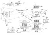
- the receiver/transmitter system 110includes a controller 28 and one or more wireless control devices 210 , such as sensors, appliances, VCRs, microwave ovens, and thermostats.
- the controller 28is capable of interfacing with various wired devices 32 , such as a camera 34 , a microphone 33 , and a motion sensor 35 , and is capable of receiving data transmissions from the wireless control devices 210 .
- the controller 28includes a main microprocessor 112 for controlling a primary wireless receiver, such as an RF receiver 114 , and a switcher circuit 124 .
- the RF receiver 114includes an RF antenna 116 for receiving RF signals transmitted by the wireless control devices 210 .
- the RF receiver 114may have its own processor or may use the resources of the main microprocessor 112 . It should be understood that any suitable receiver capable of receiving wireless communications, such as an RF or a microwave receiver is within the scope of the present invention.
- the Controllermay also include a registration channel receiver, such as an IR receiver 120 , that is capable of excluding registration of unintended or unauthorized transmitters and inadvertent registration of transmitters with unintended or unauthorized receivers.
- IR communicationsrequire line-of-sight proximity between the transmitter and receiver and are capable of excluding out or range communications. So for example, a user trying to register a wireless camera device having an IR transmitter must typically be in the same room with the receiver controller in order to effect the transmission of data therebetween and would typically not be able to communicate with a receiver controller that is located down the street or at a neighbor's house.
- encrypted communicationsare also able to exclude unauthorized communications without access to the encryption key.
- a transmittermay require a smartcard having an encryption key that is known to a particular receiver in order to communicate with that receiver, transmitters without this smartcard would not be able to communicate with the reciver.
- any suitable secure channel receivercould be substituted for the IR receiver 120 depicted in the illustrated embodiment.
- the infrared receiver 120includes an infrared signal receiver 126 , such as an LED, for receiving infrared signals emitted from the wireless control devices 210 .
- the infrared receiver 120typically uses the resources of the main microprocessor 112 , but it may include its own microprocessor.
- the switcher circuit 124is in two-way communication with the main microprocessor 112 .
- the switcher circuit 124functions to switch between various video, audio, and/or data inputs from wired control devices 32 connected thereto and functions to connect the switched inputs to an output port 143 .
- the switcher circuit 124includes a first input port 135 having a first video input 126 , a first audio input 128 and a first data input 130 .
- the video output 180 of the camera 34may be connected to the first video input 126
- the audio output 182 of the microphone 33may be connected to the first audio input 128
- the data output 184 of the motion sensor 35may be connected to the first data input 130 .
- the first input port 135can interface with any device having video, audio, and/or data outputs.
- the switcher circuit 124also includes a second input port 137 having a second video input 132 , a second audio input 134 , and a second data input 136 for communicating with a second control device 32 having video, audio, and/or data outputs.
- the switcher circuit 124can also include any number of additional input ports for interfacing with and switching between additional control devices having video, audio, and/or data outputs 32 . In the embodiment shown in FIG. 2 , two additional sets of input ports 139 and 141 are depicted.
- the input portsmay receive video, audio, and data inputs in any combination, such as a audio/video source attached to the audio and video ports of the first input port, a microphone attached to the audio input of the second port, a video-only source attached to the video input third port, and a data source attached to the data input of fourth port.
- a audio/video sourceattached to the audio and video ports of the first input port
- a microphoneattached to the audio input of the second port
- a video-only sourceattached to the video input third port
- a data sourceattached to the data input of fourth port.
- the number of portsis merely illustrative, and it is contemplated that there can be any number of switched input ports.
- the switcher circuit 124also includes an output port 143 having a video output 140 , audio output 142 , and data output 144 .
- the switcher circuitfunctions to switch between any video, audio, and/or data input of any of the input ports with the respective video, audio, and/or data output of the output port 143 .
- a communication link 138connecting the switcher circuit with the main microprocessor 112 for passing signals therebetween.
- the video 140 , audio 142 , and data 144 outputs of the switcher circuit 124are in communication with a client interface 150 , such as a USB interface set.
- the client interface 150is in communication with the client access device 22 such as a personal computer (PC).
- the switcher circuit 124switches between any of the video, audio, and data outputs of any of the device sources 32 connected thereto and the video, audio, and data feeds of the switcher output 143 for communicating the signals to the client access device 22 .
- RF and IR signals received by the RF receiver 116 and IR receiver 120may be routed by the main processor 112 to the client access device 22 .
- the controller 28includes a controller actuator 122 for switching between a DISCOVERY mode and an operational mode of the controller 28 .
- the actuatorcan be any suitable device that is capable of switching between modes of the controller, such as a mechanical button or control, a software control, an electrical control, a physical control, a tactile control, an audible control, or the like.
- the operational modes of the controllerare described in greater detail below.
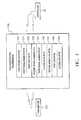
- a typical wireless control device 210is depicted in FIG. 3 . It is contemplated that the wireless control device may be any type of device such as an appliance, clock, or any device that is capable of transmitting data. In addition, the wireless control device may be a sensor type device having a sensor front end for receiving sensor data. The device depicted in the preferred embodiment is depicted as a sensor-type device since such a device encompasses other simpler wireless transmitters.
- the wireless control device 210may include a main microprocessor 212 .
- the wireless control device 210may also include a sensor front end 214 in communication with the main processor 212 . The sensor front end 214 functions to capture events and convert the event data received to a form, typically a digital form, that the microprocessor 212 understands.
- non-sensor devicesdo not include sensor front ends and merely function to transmit data. It is contemplated that a device, such as a motion detecting camera, may have a sensor front end, and, as such, can perform all the tasks of a sensor front end wireless control device as well as the tasks of a non-sensor front end wireless control device.
- the wireless control device 210further includes a non-volatile storage device 216 such as an EEPROM, ROM, or the like.
- This non-volatile storage device 216may store a unique serial number for the device; particular functional parameters of the control device; such as those for the sensor front end 214 , for use by the microprocessor 212 ; and encryption data.
- a primary channel transmittersuch as an RF transmitter circuit 220 , is provided for transmitting radio frequency signals.
- the RF transmitter circuit 220includes an RF transmitter 222 for transmitting the RF signals.
- the wireless control device 210may also include a registration channel transmitter, such as an infrared transmitter circuit 224 having an IR emitter 226 for emitting IR signals.
- the registration channelis used for securely transmitting registration information to the controller 28 . If a registration channel transmitter or receiver is not provided in the system, the primary channel is typically used to transmit registration data.
- the wireless control device 210may also include an encryption or security module or circuit 228 that includes a set of commands, programs, and/or algorithms which manipulate the data transmitted by the wireless control device to secure the transmitted data, by encryption, using code substitutions for signal “words,” XOR'ing the transmitted data, or any other suitable method for making the transmitted data more secure.
- the functionality of the encryption module 228may be incorporated into the non-volatile storage device as discussed below.
- the wireless control device 210may also include a wireless control device actuator 230 for sending a preselected or generated transmission of data to the wireless control device.
- the actuator 230may be any suitable switch-type device such as a button, switch, lever, or other mechanical, electrical, software, or the like controller. In the embodiment depicted in FIG. 3 , the actuator is illustrated as a mechanical button.
- an actuation of the wireless control device 210is not required.
- a heartbeat transmission for maintaining or synchronizing the state of the devicemay serve as the registration transmission of the registration data.
- An example of such a systemis depicted in connection with the third preferred embodiment illustrated in FIGS. 9-11 .
- a wireless control device 210in addition to sending out registration information and event transmissions, a wireless control device 210 also sends out regular heartbeat transmissions. These heartbeat transmissions may contain the same information as the registration transmissions which are typically sent out when the wireless control device actuator 230 is actuated. The order and number of the bytes for these heartbeat transmissions may be the same as the order and number of bytes of a typical registration transmission.
- the wireless device 210may be registered with the controller 28 as it would if a registration transmission was transmitted by the actuation of the actuator 230 .
- Such a heartbeat registrationis asynchronous and does not rely on human intervention.
- the controller 28Upon the registration of a wireless device by the occurrence of a heartbeat registration, the controller 28 would return to the operational mode. In this embodiment, placing the controller 28 in DISCOVERY mode is the only human intervention required.
- the wireless transmitter 210can include various types of devices and sensors such as a door contact sensor, a water level sensor, and acoustic sensor, a POWER ON sensor, a temperature sensor, a smoke sensor, a carbon monoxide sensor, a radon sensor, heat sensor, and the like.
- a POWER ON sensormay have a sensor front end that is capable of detecting a 60 Hz AC current of an electrical device.
- a water sensortypically has a front end which is able to detect an impedance when in contact with a liquid medium.
- the wireless control device 210functions to transmit RF signals via the RF transmitter circuit 220 to be received by the RF receiver antenna 116 of the controller 28 .
- the sensor front end 214receives events which are converted into electrical or digital signals and passed to the processor 212 where they are processed and passed to the RF transmitter circuit 220 for transmission.
- datais merely passed to the transmitter circuit for transmission.
- the wireless control device 210is provided with an infrared transmitter circuit 224 and is within the line of sight of the IR infrared receiver of the controller 28 , infrared transmissions may be transferred between the wireless control device 210 and the controller 28 as described in greater detail below.
- One aspect of the present inventionis concerned with the ability to automatically detect a wireless control device and register that device with the receiver/controller 28 .
- the present inventioncontemplates placing the controller 28 into a DISCOVERY mode by activating the controller actuator 122 or by otherwise placing the controller 28 in a DISCOVERY mode. In the preferred embodiment, this is done by making selections in the software interface of the client access device 22 to send an electrical transmission to the controller 28 to listen for the wireless control devices.
- controller 28there are many other suitable ways for placing the controller 28 into DISCOVERY mode, such as by actuating a mechanical or electrical button or switch located on the controller or some other associated device, by having the transmission of the wireless control device place the controller 28 in DISCOVERY MODE, by providing a voice recognition module for recognizing a command for placing the controller 28 in DISCOVERY mode spoken by the user, or the like.
- the controller 28may exit DISCOVERY mode by any suitable way, such as by activating the actuator 122 again, by automatically exiting the DISCOVERY mode upon reaching a preselected time interval, upon a successful registration event, or the like.
- the useractuates the wireless control device actuator 230 to send the preselected transmission which preferably, and not by way of limitation, includes a series of data transmissions to the receiver describing authentication information, device type information, device state, and error-checking information, as described in greater detail below.
- the control deviceis successfully registered by the system. Once registration is successful, the wireless receiver may exit DISCOVERY mode either automatically or by actuation by the user and return back to its normal operational mode.
- the controller 28needs to know that such a class of device desiring registration exists, requires registration, and needs to know how to handle them for future reference in order to complete a successful registration.
- the temperature sensor device typeis encoded as a portion of the three byte serial number discussed below. This device type is received by the microcontroller 112 via the RF antenna 116 or the IR receiver 120 . The device type is then passed to the client access device 22 and a proper entry is made in the software to associate the serial number from the wireless control device 210 just registered with the device type sent as part of that registration transmission.
- the particular wireless device and its particular functionalitiescan be unknown to the receiver at the outset and all registration data and data needed to operate the device can be transmitted during the registration process.
- the controller 28begins in discovery mode. The registration may be effected by actuating the wireless control device actuator 230 on wireless control device 210 . The transmission is sent from a wireless control device 210 to controller 28 using RF or IR signals.
- the device type information located in the serial number byte or bytes, as described below,contains the device type for an “unknown” device. This indicates to the controller 28 that information in the subsequently transmitted data bytes will contain a description of the device, including all the rules necessary to process the information from that device.
- These data bytesmay, in one embodiment, include rules as java code segments, methods, and procedures in a preselected format. Other methods of transferring rules include byte code, alternative structured programming languages, text, XML, and the like.
- the controller 28executes a set of methods to store and install the rules associated with the particular serial number of the wireless control device 210 being registered. Once the end-of-transmission is detected, the wireless control device can begin operating in operational mode and the controller 28 will contain the rules necessary to interpret the information from the wireless control device 210 in order to take proper action on that data.
- parameters that specify what type of device is being registeredmay be sent.
- a controllermay receive a transmission which specifies certain parameters that describe a device.
- the controllermay be programmed to expect certain keywords and to take particular actions based on the values of those parameters. For example, if the controller receives the keyword “rangemax” and a value 100 and a keyword “rangemin” with the value 0, it could be programmed to automatically assume that this is a device with a range element (like a slider).
- another parametermight be “button state 1” with a value of “power on” and a second “button state 2” with a value of “power off”.
- the intelligence for managing the deviceexists in the device itself, and the controller serves simply to forward the data back and forth between the client access device in the device's particular transfer medium.
- an entire java code objectin this case a device driver, could be uploaded by the device to the controller as part of registration.
- This device drivermay simply subclass the super class device driver and may be required to contain certain methods that the controller can execute in order to pass information to and from the object.
- the objectmay then be responsible for managing the export of its virtual interface, scheduling updates, interpreting transmissions from the device, or any other activities needed in order to manage and run the device.
- the controller 28In the DISCOVERY mode of the controller 28 , the controller 28 is placed in a state in which it is programmed to listen for transmissions from the wireless control devices which desire to be registered. In DISCOVERY mode, all transmissions which are not registration transmissions may, but not by way of limitation, be ignored during the process, allowing the receiver to specifically listen for particular registration transmissions from the wireless control devices and to filter out any erroneous transmissions. For example, a special signature byte, a special code in the data field, or the like can be used to identify the transmission as a registration transmission. In such a case, the controller, in discovery mode, is able to ignore all transmissions that do not have the signature byte or special registration code.
- the wireless control deviceWhen the actuator on a wireless control device is activated, the wireless control device is forced to send a preselected or generated transmission containing relevant registration information to the controller to allow the controller to properly register that device when the controller is in DISCOVERY mode.
- the preselected transmissionmay be used as a TEST-type transmission to determine whether the controller 28 is capable of receiving transmissions from the wireless control device under current conditions in order to test for out of range, impeding obstacles, excessive ambient noise, and the like.
- the registration transmissioncan be accomplished by transmitting the registration signals via the RF transmitter or the IR transmitter. Transmitting via the IR transmitter ensures that a particular controller will only receive registration transmission from wireless control devices that are within the line of sight of the controller. This is a security feature that allows the controller 28 to receive only transmissions from wireless control devices in a relatively close range and which prevents inadvertent and/or intentional registration of wireless devices by other nearby users.
- the wireless control devices 210When the wireless control devices 210 are in the operational mode, they are capable of transmitting events, such as a change of state of a door sensor (from open to closed), a scheduled heartbeat, or a maintenance signal.
- the purpose of the heartbeat or maintenance signalmay be a periodic or scheduled transmission that updates the controller 28 as to the status of the controlled wireless device 210 .
- the wireless control device actuator 230 of the wireless control device 210when the wireless control device actuator 230 of the wireless control device 210 is activated by the user, the wireless control device 210 transmits a preselected or generated transmission or series of transmissions.
- the series of transmissionsmay, in one embodiment, serve as an announcement or registration of the controlled wireless device 210 in the wireless domain.
- the test data transmissionmay serve, in one embodiment, to ensure that the wireless control device 210 is in range of the controller 28 and/or whether conditions are conducive to transmitting and receiving RF signals, i.e., there is not too much RF interference or other wireless interference and noise.
- the structure of the test or registration transmissioncomprises a series of transmissions that include authentication information, device type data, device state data, and error checking information.
- each transmission of datais a byte, or eight bits, in length.
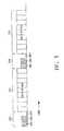
- the preferred structure of the test or registration transmission 250comprises a series of nine bytes of data.
- the first byte 252is the first of two signature bytes that is used to denote the beginning of the registration sequence.
- the second byte 254comprises the first of three serial number bytes that contain the type of the device and to provide any sort of type information necessary to process later data bytes.
- the serial number and device type dataare typically stored in the non-volatile memory 216 of the wireless device.
- the first serial number byte 254may be used to set the controller 28 into a mode where it can correctly categorize the controlled wireless device 210 . For example, information relating to the wireless device, device type, where it was purchased, its age, and the like may be encoded into the serial number information which is passed and used by controller 28 .
- the third byte 256comprises the first of two data bytes that may contain any sort of information that needs to be transmitted.
- the first data payload bytemay contain on/off information and any other discreet state information associated with the controlled wireless device 210 , such as the number of colors that a lamp may contain or the set of values to expect for a temperature sensor.
- the data contained in the first data payloadcan be combined with additional information contained in the next data bytes to fully describe the state of the device.
- the first data payload bytecan include a pan and tilt code signifying whether the update is a pan or a tilt update for a movable camera and the second data payload may contain specific pan and tilt values.
- the fourth byte 258is the second of three serial number bytes
- the fifth byte 259is the third of the three serial number bytes.
- the first, second and third serial bytestogether serve as the authentication and identification codes for the wireless control device. Once the wireless device has been successfully registered, the controller 28 may only accept transmissions from devices bearing this serial number, some other already registered serial number, or other devices that are being registered while the controller is in DISCOVERY mode.
- the sixth byte 260contains the second of two data bytes and may include any additional device specific information or the like that might be needed during the transmission.
- the seventh byte 262comprises the second of two signature bytes.
- this second signature byte 262is identical to the first signature byte 252 and is used as a data integrity check as discussed in greater detail below.
- the first signature bytecan signify which protocol is used.
- the second signature bytecan be a different value, and, when paired with the first signature byte, is understood by the controller as the total identifier expected by the protocol.
- other schemes for the signature bytesare known and within the scope of the present invention.
- the eighth 264 and ninth 266 bytescomprise a first circular redundancy check (CRC) and a second circular redundancy check (CRC) that are used to guarantee that the data is intact.
- CRCcircular redundancy check
- CRCsecond circular redundancy check
- the CRC bytes 264 and 266are used in a checksum algorithm, as is well-known in the art.
- the second signature byte 262as received by the controller 28 , must correspond to the byte expected by the practical use as described above, for the entire transmission 250 to be accepted.
- the CRC'scould take other well known forms, such as a combined 16 bit CRC, that are within the scope of the present invention. If the signature bytes are not received as expected and/or the CRC bytes do not correspond to the CRC bytes expected, the entire transmission is ignored and discarded.
- the first CRC byte and the second CRC byteare identical, as received by the controller 28 , for the transmission to be accepted. Because there is a high rate of errors triggered by many random devices transmitting random RF signals, the presence of two data integrity checks in the redundant signature bytes 252 , 262 and CRC bytes 264 and 266 ensure with a high rate of certainty that accurate data has been received by the controller 28 and not corrupted data or other noise. The fact that CRC's are built into the algorithm means that the data and serial number bytes are checked for internal integrity while at the same time providing an additional two bytes of noise cancellation.
- the controller 28knows that it has detected a successful registration and is able to successfully authenticate and process the data received from the wireless device.
- the serial numbersserve as an authentication token and prevent interference from nearby controllers 28 and wireless devices in the user's space; spurious transmissions will be ignored because the serial numbers of these spurious devices are not registered with a particular controller 28 .
- the DISCOVERY mode of the controller 28may automatically time out or otherwise automatically end, whereupon the controller 28 returns to its normal operational mode. Alternatively, the controller 28 may be manually switched by the user to its normal operational mode by activating the actuator 122 .
- the embodiment discussedillustrates a nine byte transmission scheme. It should be understood that the number of transmissions or the transmission length may contain any number of identification or signature bytes, data bytes, CRC bytes, or other checksum techniques for ensuring internal data integrity.
- the data bytesmay contain any type of data besides sensor data, such as algorithms, hardware descriptions, encrypted data, video, audio, number of expected bytes, and the like.
- the protocol of the present inventionworks as a one-way protocol, i.e., no response, acknowledgment or other transmission is required from the controller 28 . It should also be understood that the protocol works for up to N-way communications, where N is greater than or equal to 1. By N-ways, it is contemplated that a wireless control device may in fact register with multiple controllers 28 simultaneously or at different times.
- a unique tokenmay be transmitted along with the device registration transmission.
- the unique tokenis verified to be acceptable by any suitable registration or verification entity, such as the server 14 illustrated in the third preferred embodiment, whereupon the wireless control device 210 is successfully registered.
- the unique tokenmay be encoded in the three serial number bytes 254 , 258 , 259 which are transmitted to the controller 28 during a registration transmission.
- the controller 28would send the unique token to the server 14 (FIG. 9 ), perhaps by way of the client access device 22 .
- the controller 22would receive back a response from the server notifying the controller whether that token was accepted by the server.
- Such a methodis useful to detect whether the wireless control device has been previously registered in the system 110 . If a proper user successfully registered the wireless control device previously, then the unique token would already be present on the server. If a second malicious user attempted to register the same wireless control device with the system 110 , the server would refuse the attempted registration due to the previous registration by the proper user.
- the present inventionsolves the clock drift problem by inserting a synchronization pulse 290 at the beginning of each byte of data 292 transmitted by the wireless control device 210 .
- the synchronization pulse 290is three bits in length and comprises two ON bits followed by an OFF bit. The receiver recognizes this pattern as being a synchronization pulse and resynchronizes its clock at the trailing edge of the second ON bit.
- the transmitter and receivermay stay in synchronization for a number of data bits transferred. For example, for a bit rate of 2400 bits/sec. (4 MHz), a tolerance of ⁇ 10 MHz, and a clock, the receiver transmitter system 110 is able to stay reliably in synchronization for at least 8 bits of transmitted data, which is sufficient to transmit one byte of data. It has been found that as long as the clock drift is less than 1 ⁇ 2 of one bit by the conclusion of an eight bit transmission that the problem of clock drift is eliminated. Of course it should be understood that other combinations of factors could be used to accomplish the task of maintaining the synchronization of a relatively unstable clock over a selected data transmission window.
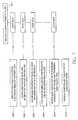
- FIGS. 6 and 7we demonstrate how to securely and authentically communicate between wireless control devices and a controller and show how registration of wireless control devices takes place in order for this to happen.
- a first proper controller 2500 and a second malicious controller 2505are depicted.
- a wireless control device 2504first registers with the proper controller, and subsequently, a malicious user attempts to spy on the wireless control device 2504 registered with the proper controller 2500 . The malicious user does this by way of attempting to register the wireless control device 2504 with the malicious controller 2505 , thus, hoping to capture all events and data from the wireless control device 2504 during operation.
- This embodimentcontemplates detecting and notifying the user of such a security breach and as a way of showing the system described in connection with the first embodiment in a practical scenario.
- the proper controller 2500is placed in to DISCOVERY mode by the proper user by actuating the proper controller actuator 2502 .
- DISCOVERY modethe proper controller 2500 is in a mode where it is listening for IR and/or RF registration information from one or more wireless control devices that the proper user wishes to register.
- the wireless control device 2504an outdoor motion detecting camera, is placed in IR line of sight 2509 with respect to the proper controller 2500 .
- the wireless control device actuator 2506 located on the wireless controlled camera 2504embodied as a push button, is actuated by the proper user.
- the wireless controlled camera 2504transmits registration information 2508 via IR and RF signals to the proper controller 2500 . This registration information is in the form of two packets of identical data, one via IR and one via RF, containing, in order,
- step 2006the proper wireless controller 2500 receives the RF registration packet via the RF antenna 2510 .
- the proper controller 2500attempts to determine whether a wireless control device with the transmitted serial number 2505 has previously been registered. Since this is the first time that this registration is taking place, the proper controller 2500 , with the assistance of client access device 2512 , determines that such a serial number does not exist. Thus, the registration packet 2508 is ignored on the RF side. On the IR side, however, the proper controller 2500 receives the registration packet via the IR receiver 2514 . The proper controller 2500 parses the registration packet and attempts to determine whether a wireless control device having the transmitted serial number 2505 has been previously registered.
- the proper controller 2500registers the wireless control device 2504 by cataloging the relevant data along with the transmitted serial number 2505 and the encryption byte 2507 . Any future transmissions from the wireless controlled camera 2504 will contain encrypted data bytes which are encrypted using the encryption byte 2507 , until the wireless controlled actuator 2506 is pushed again.
- the IR registration methodto register the wireless devices the first time, i.e., ignoring all transmissions from any unregistered wireless control devices 2520 , including registrations transmitted via RF signals, the present system greatly limits the problem of accidently registering the wireless controlled camera 2504 along with other unregistered controllers 2520 located within RF range. Moreover, requiring registration via IR to take place first, prevents unintended wireless control devices from unintentionally registering with local controller 2500 .
- step 2008the wireless controlled camera 2504 is moved out of IR line of sight to a location 2516 that remains within RPF range.
- the useractuates the wireless controlled camera actuator 2506 .
- a registration/test packet 2518is sent from the wireless controlled camera 2504 to the proper controller 2500 via RF signals.
- wireless controlled camera 2504has also sent an IR transmission, but because wireless controlled camera 2504 is out of IR line of sight of the proper controller 2500 , this mode of transmission will not be picked up by the controller.
- the registration/test packet 2518includes
- the new encryption byte 2522will be used to encrypt all future transmission data bytes from wireless controlled camera 2504 to proper controller 2500 until the actuator 2506 is actuated again.
- the proper controller 2500remains in DISCOVERY mode, receives a registration/test packet via RF and attempts to update the registration information of the previously registered wireless controlled camera 2504 stored therein, notably the new encryption key 2522 which will be used to decrypt future transmissions.
- the proper controlleris taken out of discovery mode by any suitable means including actuating the proper controller actuator 2502 .
- step 2012a malicious user attempts to spy on the proper user's wireless controlled camera 2504 by registering it in a process very similar to steps 2000 - 2006 .
- the details of this registration attemptclosely mimic that described in steps 2000 - 2006 and are obvious to those skilled in the art.
- the steps in the authorized registration corresponding to steps in the malicious registrationare steps 2000 and 2014 , steps 2002 and 2016 , steps 2004 and 2018 , and steps 2008 and 2020 .
- a registration/test packet 2524is sent to both the proper 2500 , and malicious 2505 controllers via IR and RF.
- the proper controller 2500does not receive the IR transmission, since it is not in IR range. Since the proper controller 2500 is in operational mode instead of DISCOVERY mode, it is alerted to the fact that a possible spy has attempted to register the wireless controller 2504 . Thus, this condition is communicated to the end user via the web site as is discussed below, and the user can take appropriate action.
- FIG. 9shows an illustrative system 10 in accordance with a third embodiment of the present invention.
- an illustrative client-server based embodiment of the present inventionis herein described.
- the system 10illustrates how the wireless system 10 can be incorporated into a larger more encompassing client-server system. Similar references symbols are used throughout the embodiments to show like components.
- System 10may include an installation 12 and a remote site 14 that may be linked via a communications network 16 .
- Remote site 14may be any suitable remote site that may include equipment such as, for example, one or more servers, mainframes, personal computers, or any other suitable computer-based equipment.
- Remote site 14may include a network of suitable computers that may be interconnected in any suitable way, such as, for example, through a local area network, wide area network, telephone network, cable television network, Intranet, Internet, or any other suitable wired or wireless communications network.
- Communications network 16may be any suitable communications network, such as, for example, a local area network, wide area network, telephone network, cable television network, Intranet, Internet, or any other suitable wired or wireless communications network.
- Some suitable wireless communications networksmay be global system for mobile communications (GSM), time-division multiple access (TDMA), code-division multiple access (CDMA), Bluetooth, or any other suitable wireless communication networks.
- GSMglobal system for mobile communications
- TDMAtime-division multiple access
- CDMAcode-division multiple access
- Bluetoothor any other suitable wireless communication networks.
- Installation 12 and remote site 14may communicate over communications network 16 using any suitable protocol or protocol stack.
- installation 12 and remote site 14may communicate via a transmission control protocol/Internet protocol (TCP/IP) environment using, for example, IP version 4 or IP version 6 (that supports 128-bit network addressing) and a hypertext transfer protocol (HTTP).
- TCP/IPtransmission control protocol/Internet protocol
- HTTPhypertext transfer protocol
- UDPuniversal plug and play
- Any suitable request-response type of protocol and socket-based packet transport stack, or suitable peer-to-peer communications approachmay be used as desired.
- Installation 12 and remote site 14may communicate using any suitable communications. Communications may include, for example, commands, requests, messages, remote procedure calls (e.g., using a proxy-stub pair), or any other suitable client-server or peer-to-peer communication. Communications may also involve, for example, complex communications between application constructs running on installation 12 and remote site 14 .
- Objects running on the client and servermay, for example, communicate using an Object Request Broker (ORB).
- Transmitted informationmay, for example, be encapsulated as COM objects or Javabeans and persisted to files that are transmitted over a remote access link.
- access communicationsmay include hypertext markup language (HTML) formatted markup language documents (e.g., web pages), that are exchanged between installation 12 and remote site 14 via ISP 23 and communications link 16 .
- HTTPhypertext markup language
- communicationsmay comprise of a series of HTTP posts and responses in which the parameters for the transmissions may be sent as name/value pairs in the normal post method.
- numbered commandsmay be parsed out and executed at remote site 14 .
- Remote site 14may be responsible for parsing the command string into individual commands and executing each of those commands.
- remote site 14may utilize a script language and interpreter such as Personal Home Page Tools (PHP) which is embedded within a Web page along with its Hypertext Markup Language (HTML).
- PHPPersonal Home Page Tools
- HTMLHypertext Markup Language
- the Web servermay call PHP to interpret and perform the operations called for.
- PHPHypertext Markup Language
- Other similar technologiesmay also be utilized such as JavaScript, Microsoft's VBScript, or any other applicable script interpreter. If desired, any other suitable client-server or peer-to-peer based approach may be used.
- Installation 12may be operated by a local user.
- Installation 12may include one or more nodes.
- FIG. 9illustrates an approach having two nodes, first user node 18 and second user node 20 .
- nodes 18 and 20may be located at a single location, such as the user's main residence. If desired, nodes may be located across more than one location. For example, one node may be in a user's main residence and another at the user's vacation house.
- user node 18may include a client device 22 that may be connected to communications network 16 .
- client device 22may be connected to the Internet via an Internet service provider (ISP) 23 .
- ISPInternet service provider
- Client device 22may be any device suitable for communicating with remote site 14 via communications network 16 .
- client device 22may be a computer, a personal digital assistant (PDA), a terminal, a set-top box, or any other suitable device that provides access to remote site 14 via communications network 16 .
- Client device 22may include, for example, an Internet browser application 26 that may be used to access web pages via communications network 16 .
- client device 22may run a client application that provides locally generated displays propagated with a format obtained using any suitable client-server or peer-to-peer scheme.
- Client device 22may communicate with ISP 23 or directly with communications network 16 using any suitable communications link.
- the linkmay include a telephone dial-up link, digital subscriber lines (DSL), a cable modem link (e.g., a data over cable service interface specification (DOCSIS)), a satellite link, a computer network link (e.g., Ethernet link, T 1 line, etc.) or any other suitable communications link or combination of communications links.
- DSLdigital subscriber lines
- DOCSISdata over cable service interface specification
- satellite linke.g., a satellite link
- DOCSISdata over cable service interface specification
- computer network linke.g., Ethernet link, T 1 line, etc.
- Remote site 14may include one or more servers such as, for example, web server 46 and database server 48 .
- Database server 48may maintain database 58 .
- remote site 14may include an application server and any other suitable server or combination of servers.
- serveris not limited to a distinct piece of computing hardware or storage hardware, but may also be a software application or a combination of hardware and software.
- one computermay have software that enables the computer to act as both a web server and as a database server.
- remote site 14may provide displays or display definitions to client device 22 .
- web server 46may generate static and dynamic web pages from data supplied by database server 48 .
- Web page 47may be viewed by a user using Internet browser 26 running on client device 22 .
- Software applications interfacing installation 12 with remote site 14may be created using any suitable platform and/or software development tools.
- Java 2 Enterprise Edition, Javabeans, component object model (COM) based technologiese.g., ActiveX, object linking and embedding (OLE), etc.
- Javascript, Visual Basic, C, C++, scripting languages, or any combination of these or other suitable development toolsmay be used in creating the software interface between installation 12 and remote site 14 (e.g., web-page interface). Any combination of these or other suitable development tools may be used in preparing any other software modules or applications for use in any other suitable facet of the present invention.
- Remote site 14may function as the master controller of the system shown in system 10 .
- usersmay access the system shown in system 10 via any computer, monitoring module, or remote user access device linked to communications network 16 .
- Remote user access devices(such as remote user access device 17 in FIG. 9 ) may include, for example, personal digital assistants, cellular telephones, set-top boxes, personal computers, or any other suitable device a user may use to access remote site 14 via communications network 16 .
- Monitoring modules 28may serve as an interface between remote site 14 and at least one control device 32 .
- the monitoring module 28is equivalent to the controller 28 referred to in the embodiment of FIGS. 1-4 .
- Monitoring modules 28may be any suitable hardware, software, or a combination thereof and may be included at any point within the system.
- monitoring module 28may be a software application running on client device 22 or a separate piece of hardware that may be connected to client device 22 (as shown at node 18 ) or partially implemented as software on client device 22 and a separate piece of hardware.
- monitoring module 28may be a stand-alone appliance (as shown at node 20 ) connected to communications network 16 , operating separately and independently from client device 22 .
- Each monitoring modulemay be shipped with a model identification code, or with the capacity to generate such a code, that may serve to identify each particular monitoring module's model type.
- Monitoring modulesmay be installed at one or more locations. Monitoring modules may be installed by the user (or any other suitable person) by, for example, connecting the modules to client device 22 that may communicate with remote site 14 over communications network 16 .
- the connection between the monitoring module and the client access device and between devices and the monitoring modulemay be in the form of a universal serial bus (USB) connection, parallel port connection, serial connection (e.g., RS-232), Firewire connection, any combination of these, or any other suitable type of connection.
- USBuniversal serial bus
- serial connectione.g., RS-232
- Firewire connectionany combination of these, or any other suitable type of connection.
- monitoring modulesmay be given the capability (e.g., processing hardware, communications equipment, etc.) to communicate, via communications network 16 , without the use of a client access device.
- Monitoring modulesmay link attached devices or appliances (e.g., sensors, cameras, microwaves, refrigerators, etc.) with remote site 14 via communications network 16 .
- One or more monitoring modules 28may provide data from attached devices and appliances to remote site 14 via communications network 16 .
- the term “device,” as defined herein,shall include any suitable device or appliance whether it is wired or wireless.
- At least one device 32may be interfaced with and controlled by each monitoring module 28 . Connections between monitoring module 28 and the various devices 32 may be hardwired or wireless such as described in connection with the first embodiment of FIGS. 1-4 . Devices 32 may encompass any suitable device capable of being controlled or mediated by an external controller. Such devices may include, but are not limited to, a camera 34 , a radio 36 , a wireless smoke or fire detector 38 , a wireless contact sensor 40 , and a wireless light switch 41 .
- suitable devicesmay include, for example, various audio input and output devices, various visual displays, washers/driers, microwave ovens, cooking ranges, car alarms, plant watering devices, sprinkler, thermostats, carbon monoxide sensors, humidistats, rain gauges, video cassette recorders, radio tuners, or any other suitable device and the like.
- One or more notification devicesmay also be incorporated into the system. As illustrated in FIG. 9 , pager 43 is in wireless communication with a wireless or cellular transmitter 44 associated with remote site 14 .
- Other suitable notification devicesinclude, for example, e-mail clients, wireless hand-held computers, wireless wearable computer units, automatic web notification via dynamic web content, telephone clients, voice mail clients, cellular telephones, instant messaging clients, and the like.
- System 10provides users with opportunities to remotely control and monitor devices 32 using remote user access devices 17 via communications network 16 .
- usersmay control devices 32 that are interfaced with monitoring modules 28 at node 18 and devices 32 interfaced with monitoring module 28 at node 20 .
- theremay be a single node, or more nodes, depending on, for example, the user's equipment, number of sites, or other suitable parameters.
- a suitable system architecture and communications network 16may allow users, or anyone that users permit, to readily monitor and control monitoring modules 28 from any location using any suitable device that is capable of communicating with remote site 14 via communications network 16 .
- usersmay access installation 12 using remote user access devices 17 without the use of remote site 14 .
- remote user access devices 17may be used to communicate with monitoring modules 28 of installation 12 via communication network 16 and ISP 23 . If desired, two-way communications may be implemented using this approach.
- Remote user access devicemay access installation 12 using, for example, special IP addresses assigned to a particular monitoring module, node, installation, or any other suitable element of the installation. The use of IP addresses is merely illustrative. Any other suitable addressing may be used to allow access to an installation from a remote used access device.
- Devices 32may be programmed at the installation in terms of how they respond to certain events (e.g., what does the camera do when the contact sensor is triggered?). Alternatively, devices 32 may be programmed from a remote location using remote user access device 17 , for example. The programming may be stored in devices 32 , monitoring modules 28 , or at remote site 14 .
- contact sensor 40 of FIG. 9may be associated with the front door (not shown) of a remote location associated with second node 20 .
- Contact sensor 40may be configured to trip whenever the front door is opened.
- Camera 34is also positioned to view the front door location and may be programmed to take a digital picture whenever the sensor contact 40 is tripped. This picture may be transmitted over communications network 16 and stored in database server 48 .
- an event notification or alarm triggermay be transmitted by monitoring module 28 to database server 48 .
- Database server 48may have been previously programmed to transmit a notification event to the user's pager, for example, via cellular transmitter 44 .
- camera 34may take a picture of the front door and may transmit that picture, via monitoring module 28 and communications network 16 , to database server 48 .
- the userhaving been notified via pager 42 , may now access the picture using web server 46 of remote site 14 via Internet browser 26 . In this way, the user may determine who has entered the front door of his or her home.
- system 10may allow a user located at one node 18 to control a device at a second node 20 .
- the usermay contact web server 46 via, for example, Internet browser 26 of node 18 in order to access a database entry for light switch 41 of node 20 .
- a virtual representation of the light switch 41may be made available to the user by web server 46 and may be manipulated by the user to remotely change the state of light switch 41 and the connected lamp 42 .
- the systemmay allow the user to change the state of lamp 42 from being “off” to being “on” by, for example, manipulating the virtual light switch from web server 46 and a corresponding command would be placed in the queue of waiting commands on the server component.
- the controlling module or monitor 28may poll remote site 14 looking for waiting commands, such as the change state command of light switch 41 . Thereafter, the command may be transmitted to monitoring device 28 that would instruct the light switch to change from the “off” state to the “on” state, thus turning on lamp 46 .
- This change in state of lamp 46may be viewed by an appropriately positioned camera, such as camera 34 , which would be used to visually monitor the remote location 20 to determine whether the command had been completed successfully. If the command had not been successfully completed, then an error message may be communicated to the user, using for example, the means specified by the user's notification preferences or through any other suitable means of communicating information to the user. This is merely an illustrative approach for detecting a change is state of a device.
- lamp 46may be in two-way communications with a corresponding device driver.
- the device drivermay query the lamp to determine whether it was on after executing a “turn on” command. Any such suitable approach may be used for detecting a state in change of a device.
- monitoring module 28may serve, for example, as a common connection point for one or more devices 32 at an installation 12 and as the interface between devices 32 and remote site 14 via communications network 16 .
- Monitoring module or service broker 28may, for example, serve as a translation and brokering agent between remote site 14 and devices 32 .
- monitoring module 28may be software made up of multiple dynamically loaded objects, or device descriptors 49 , that may allow remote site 14 to interface with the devices 32 .
- the dynamically loaded device descriptors 49may act as device drivers for devices 32 , translating, in both directions, monitoring, command, and control data exchanged between monitoring module 28 and remote site 14 via communications network 16 .
- Each device descriptor 49may also translate the signals received from monitoring module 28 into the specific electrical signals that are required to communicate with (both input and output) and control its associated device 32 .
- Device descriptor 49may be provided for each specific device 32 when, for example, different devices 32 have different interfaces and require specific sets of electrical signals for their monitor and control.
- Device descriptors 49may include, for example, a manufacturer identification, product identification, and driver version number to allow a device to be referenced correctly. Once a new device 32 has been detected and is to be integrated into the system, monitoring module 28 may reference, download, and run the appropriate drivers for the new device.
- monitoring module 28may communicate with remote site 14 to determine whether device 32 has been previously catalogued. Monitoring module 28 may, for example, determine if a general description and a default state of device 32 exists at the remote site.
- a device 32When a device 32 has been catalogued, then, for example, static parameters, such as the manufacturer name, may be communicated from monitoring module 28 to remote site 14 and the default state of device 32 may exist at remote site 14 .
- device 32When a device 32 is not already catalogued, device 32 may communicate its default state and static parameters to monitoring module 28 that may, in turn, communicate the default state and static parameters to remote site 14 .
- the communication from monitoring module 28 to remote site 14may be done using name/value pairs using, for example, the normal HTTP post method discussed hereinbefore.
- a template documentmay be a static parameter of device 32 .
- FIG. 11shows five devices, 32 , 32 a , 32 b , 32 c , 32 d .
- Each devicemay be interfaced to a monitoring module 28 via a device descriptor or driver 49 (only one shown).
- Each devicemay include a customizable user interface 58 that may be viewable on a remote user access device over communications network 16 .
- Interfaces 58may include virtual representations of the actual user interfaces of the devices.
- virtual representationsmay be stored on, for example, web server 46 .
- Remote site 14may use changes in device states to change the virtual representations of the devices with which the changed states are associated.
- a virtual representation of a devicemay be either a text-based, symbol-based, or image-based representation of an actual device 32 from the installation as it appears to a user who accesses the remote site from a location remote to the installation using any suitable remote user access device.
- the corresponding virtual representationmay be an indicator icon that may be either green or red. If the indicator icon is green, that may denote that the actual light switch is in the “on” position. If the indicator is red, that may denote that the light switch is in the “off” position. If, during a heartbeat operation, remote site 14 is informed that the state of the light switch changes from “on” to “off,” then the virtual representation of the light switch may change from being green to being red.
- User interface 58may include at least one resource.
- resources 60 , 62 , and 64are shown. Resources may provide users with access to features specific to their associated device.
- the device shown in FIG. 11represents a videocassette recorder (VCR) having a recording setting resource 60 , a channel selecting resource 62 , and a power selecting resource 64 .
- VCRvideocassette recorder
- Typical VCRsmay have other operational resources, but the resources illustrated in FIG. 11 are sufficient to illustrate the operation of the device.
- Each resource 60 , 62 , 64may include one or more display components.
- the recording setting resource 60includes a display component 70 and a series of pushbuttons 72 , 74 , 76 , 78 which a user may use to activate the VCR's fast forward, reverse, play, and stop functions, respectively.
- the channel selecting resource 62may include the display component 70 and a pair of pushbuttons 82 that users may use to activate up channel and down channel functions of the VCR.
- the power selecting resource 64may include a toggle switch 80 that user may use to activate the VCR's power on and power off commands, and an LED indicator 81 that may indicate the power condition of the VCR.
- Other suitable display componentsmay include toggle buttons, radio buttons, absolute sliders, proportional sliders, edit fields, labels, images, video clips, streaming video, streaming audio, multiselect list, time fields, date fields, N-directional components, N-state buttons, N-state selectors (where N may be any suitable integer), trees, tables, graphs, charts, drawing pads, streaming audio, banners, or any other suitable display components.
- Display componentsmay act as status indicators. If desired, display components allow users to toggle settings or otherwise manipulate devices 32 .
- toggle buttonsmay serve as indicators, showing, for example, whether a device is in the “on” position or in the “off” position.
- Toggle buttonsmay allow users to change the state of a device, by, for example, turning a device on or off.
- Slidersmay act as indicators by showing, for example, the percentage complete of a particular process a device may be performing (e.g., baking a cake), and may allow users to change the state of a device (e.g., changing the thermostat temperature).
- Edit fieldsmay allow users to change textual representations of suitable elements (e.g., naming a television show to be recorded by the show's name).
- Video, audio, images, or any other suitable media-based componentsmay act as indicators showing what the devices are sensing (e.g., images may be sensed by cameras, streaming video may be sensed by camcorders, audio clips may be sensed by audio recorders, etc.).
- Date and time fieldsmay act as indicators, by, for example, displaying what date and time a VCR is set to start recording.
- Date and time fieldsmay allow users to set the date and time a VCR may start recording.
- Multiselect listsmay act as indicators by, for example, listing all sound sensors that are detecting noise in the house. Multiselect lists may also be used, for example, to select some of a number of available sensors to turn on.
- a virtual representation of each device 32 , 32 a , 32 b , 32 c , 32 dmay be stored as a record 94 , 94 a , 94 b , 94 c , 94 d in the database of database server 48 of remote site 14 .
- Each recordmay contain an entry for each resource and its associated components which make up the device.
- record 94 for VCR device 32may contain an entry 90 , 91 , 92 for each resource 60 , 62 , and 64 , respectively, and an entry 90 a , 90 b , 90 c , 90 d , 91 a , 91 b , 92 a , and 92 b for each component 70 , 72 , 72 , 74 , 80 , 81 , and 82 , respectively.
- a web page 47may be generated by web server 46 by extracting the associated record for that device from database server 48 and creating a graphical, textual, tactile, aural, or other similar modality user interface representation of that device that the user may access via, for example, Internet browser 26 .
- monitoring module 28may serve is to persist the state of devices 32 . This may be done, for example, to allow the real-time states of devices 32 to be stored, to communicate to remote site 14 , or to allow for easy recovery from a system crash.
- the stored state of devices 32may also be used for maintaining a synchronized relationship between an installation 12 and remote site 14 .
- remote site 14 and installation 12may use polling and heartbeat mechanisms in order to synchronize state information between remote site 14 and installation 12 .
- Pollingmay refer to a process whereby monitoring module 28 obtains commands from remote site 14 .
- the commandsmay reside, for example, in command queue 51 .
- Commandsmay be accumulated at command queue 51 as a result of any suitable action by the user, by remote site 14 , or by both.
- a usermay use a remote user access device to issue a command or a request to remote site 14 to cause a change in state of one of devices 32 (e.g., to turn a lamp on).
- Remote site 14may post the change in state command to a command queue 51 .
- Monitoring module 28may communicate a request for pending commands to remote site 14 . This request may be communicated periodically as part of the polling process. In response to the monitoring module's request, remote site 14 may provide one or more pending commands from command queue 51 , and may notify monitoring module 28 of the number of remaining pending commands in command queue 51 . Monitoring module 28 may then again communicate a request for pending commands. Remote site 14 may return more of the pending commands from command queue 51 . This process may continue until command queue 51 at remote site 14 is empty.
- Remote site 14may provide commands to monitoring module 28 using any suitable algorithm. For example, remote site 14 may return commands using first-come, first-serve, round robin, first-in, first-out, weighted prioritization, or any other suitable algorithm. Remote site 14 may also proactively inform monitoring module 28 that commands are waiting in queue 51 . Monitoring module 28 may then poll remote site 14 and retrieve commands from remote site 14 until the queue is empty.
- monitoring module 28may use heartbeat process 52 to update device state information at remote site 14 .
- a heartbeatmay be a periodic communication from monitoring module 28 to remote site 14 containing updated state information for devices 32 associated with monitoring module 28 .
- monitoring module 28may send a communication to remote site 14 in response to a change in state of a device 32 , a synchronization of a device 32 with remote site 14 , a triggered alert event, or in response to any other suitable event.
- all data intended to be transmitted to remote site 14may be transmitted to remote site 14 via communications network 16 .
- Remote site 14may transmit an acknowledgment of receipt and successful processing of the data back to monitoring module 28 .
- Remote site 14may direct monitoring module 28 to make changes in its own state by, for example, posting commands to data store 51 .
- remote site 14may post commands that set or modify the polling 50 or heartbeat 52 time intervals.
- monitoring module 28may send a communication to remote site 14 , requesting any queued commands.
- Monitoring module 28may continue to poll, using a preselected communication scheme, until the queue of commands waiting for monitoring module 28 is empty. Each command received from the queue may be acted upon when the command is received and any associated state changes are effected.
- Remote site 14may transmit an acknowledgment of receipt and successful processing of the data back to monitoring module 28 .
- remote site 14may send unsolicited communications to monitoring module 28 .
- Remote site 14may send communications to, for example, set or update the heartbeat or polling time, or to cause monitoring module 28 to issue a command to update a component of a device.
- Remote site 14may send unsolicited communications to monitoring module 28 for any other suitable purpose.
- monitoring module 28may also take care of many network level activities 56 . These activities may include, but are not limited to verifying passwords, dialing up an ISP, if necessary, periodically uploading accounting/billing information, and performing security measures. Any other suitable network level activities may be performed by monitoring module 28 .
Landscapes
- Engineering & Computer Science (AREA)
- Computer Security & Cryptography (AREA)
- Computer Networks & Wireless Communication (AREA)
- Signal Processing (AREA)
- Computer Hardware Design (AREA)
- Computing Systems (AREA)
- General Engineering & Computer Science (AREA)
- Databases & Information Systems (AREA)
- Selective Calling Equipment (AREA)
Abstract
Description
Claims (58)
Priority Applications (4)
| Application Number | Priority Date | Filing Date | Title |
|---|---|---|---|
| US09/776,071US7039391B2 (en) | 2000-11-28 | 2001-02-01 | Method and system for communicating with a wireless device |
| PCT/US2001/044458WO2002045400A1 (en) | 2000-11-28 | 2001-11-28 | Method and system for communicating with a wireless device |
| AU2002226996AAU2002226996A1 (en) | 2000-11-28 | 2001-11-28 | Method and system for communicating with a wireless device |
| US10/939,040US20050164678A1 (en) | 2000-11-28 | 2004-09-10 | Method and system for communicating with a wireless device |
Applications Claiming Priority (4)
| Application Number | Priority Date | Filing Date | Title |
|---|---|---|---|
| US25335800P | 2000-11-28 | 2000-11-28 | |
| US25335900P | 2000-11-28 | 2000-11-28 | |
| US25346400P | 2000-11-28 | 2000-11-28 | |
| US09/776,071US7039391B2 (en) | 2000-11-28 | 2001-02-01 | Method and system for communicating with a wireless device |
Related Child Applications (1)
| Application Number | Title | Priority Date | Filing Date |
|---|---|---|---|
| US10/939,040DivisionUS20050164678A1 (en) | 2000-11-28 | 2004-09-10 | Method and system for communicating with a wireless device |
Publications (2)
| Publication Number | Publication Date |
|---|---|
| US20020077077A1 US20020077077A1 (en) | 2002-06-20 |
| US7039391B2true US7039391B2 (en) | 2006-05-02 |
Family
ID=27500469
Family Applications (2)
| Application Number | Title | Priority Date | Filing Date |
|---|---|---|---|
| US09/776,071Expired - Fee RelatedUS7039391B2 (en) | 2000-11-28 | 2001-02-01 | Method and system for communicating with a wireless device |
| US10/939,040AbandonedUS20050164678A1 (en) | 2000-11-28 | 2004-09-10 | Method and system for communicating with a wireless device |
Family Applications After (1)
| Application Number | Title | Priority Date | Filing Date |
|---|---|---|---|
| US10/939,040AbandonedUS20050164678A1 (en) | 2000-11-28 | 2004-09-10 | Method and system for communicating with a wireless device |
Country Status (3)
| Country | Link |
|---|---|
| US (2) | US7039391B2 (en) |
| AU (1) | AU2002226996A1 (en) |
| WO (1) | WO2002045400A1 (en) |
Cited By (137)
| Publication number | Priority date | Publication date | Assignee | Title |
|---|---|---|---|---|
| US20030233660A1 (en)* | 2002-06-18 | 2003-12-18 | Bellsouth Intellectual Property Corporation | Device interaction |
| US20040117834A1 (en)* | 2002-12-11 | 2004-06-17 | Jeyhan Karaoguz | Server architecture supporting a personal media exchange network |
| US20050010417A1 (en)* | 2003-07-11 | 2005-01-13 | Holmes David W. | Simplified wireless device pairing |
| US20050270151A1 (en)* | 2003-08-22 | 2005-12-08 | Honeywell International, Inc. | RF interconnected HVAC system and security system |
| US20060181430A1 (en)* | 2005-01-19 | 2006-08-17 | Lg Electronics Inc. | Method and apparatus for automatically recognizing/establishing remote-controller communication mode for use in digital electronic devices |
| US20060195412A1 (en)* | 2002-06-18 | 2006-08-31 | Bellsouth Intellectual Property Corporation | Learning device interaction rules |
| US20060200557A1 (en)* | 2002-06-18 | 2006-09-07 | Bellsouth Intellectual Property Corporation | Notification device interaction |
| US20060218401A1 (en)* | 2005-03-24 | 2006-09-28 | Samsung Electronics Co., Ltd. | System and method of sharing contents data in network |
| US20060272030A1 (en)* | 2002-06-18 | 2006-11-30 | Bellsouth Intellectual Property Corporation | Content control in a device environment |
| US20070165863A1 (en)* | 2006-01-19 | 2007-07-19 | Research In Motion Limited | System and method for secure PIN exchange |
| US20070209057A1 (en)* | 2006-03-01 | 2007-09-06 | Broadband Wizard Inc. | Wireless delivery of broadband cable signals |
| US20070229250A1 (en)* | 2006-03-28 | 2007-10-04 | Wireless Lighting Technologies, Llc | Wireless lighting |
| US20080125041A1 (en)* | 2006-11-24 | 2008-05-29 | Sony Ericsson Mobile Communications Ab | Ad-hoc connectivity system and method |
| US20090070681A1 (en)* | 2005-03-16 | 2009-03-12 | Dawes Paul J | Security System With Networked Touchscreen and Gateway |
| US20090070477A1 (en)* | 2005-03-16 | 2009-03-12 | Marc Baum | Controlling Data Routing Among Networks |
| US20090066789A1 (en)* | 2005-03-16 | 2009-03-12 | Marc Baum | Device for Data Routing in Networks |
| US20090066788A1 (en)* | 2005-03-16 | 2009-03-12 | Marc Baum | System for Data Routing in Networks |
| US20090070436A1 (en)* | 2005-03-16 | 2009-03-12 | Dawes Paul J | Networked Touchscreen With Integrated Interfaces |
| US20090070682A1 (en)* | 2005-03-16 | 2009-03-12 | Dawes Paul J | Security System With Networked Touchscreen |
| US20090070473A1 (en)* | 2005-03-16 | 2009-03-12 | Marc Baum | Method for Data Routing in Networks |
| US20090070692A1 (en)* | 2005-03-16 | 2009-03-12 | Dawes Paul J | Method For Networked Touchscreen With Integrated Interfaces |
| US20090077623A1 (en)* | 2005-03-16 | 2009-03-19 | Marc Baum | Security Network Integrating Security System and Network Devices |
| US20090077167A1 (en)* | 2005-03-16 | 2009-03-19 | Marc Baum | Forming A Security Network Including Integrated Security System Components |
| US20090074184A1 (en)* | 2005-03-16 | 2009-03-19 | Marc Baum | Controlling Data Routing in Integrated Security Systems |
| US20090077624A1 (en)* | 2005-03-16 | 2009-03-19 | Marc Baum | Forming A Security Network Including Integrated Security System Components and Network Devices |
| US20090138958A1 (en)* | 2005-03-16 | 2009-05-28 | Marc Baum | Takeover Processes in Security Network Integrated with Premise Security System |
| US20090138928A1 (en)* | 2002-12-11 | 2009-05-28 | Broadcom Corporation | Media processing system based on satellite set top box platform with telephony downstream and upstream data paths |
| US20090165114A1 (en)* | 2005-03-16 | 2009-06-25 | Marc Baum | Takeover Processes in Security Network Integrated with Premise Security System |
| US20090240817A1 (en)* | 2005-03-23 | 2009-09-24 | Michael Meyer | System and method for transporting data units through a communication network |
| US20100023865A1 (en)* | 2005-03-16 | 2010-01-28 | Jim Fulker | Cross-Client Sensor User Interface in an Integrated Security Network |
| US20100054138A1 (en)* | 2008-09-03 | 2010-03-04 | Jonathan Gips | Discovery protocol |
| US20100052612A1 (en)* | 2008-08-29 | 2010-03-04 | Reza Raji | Battery-Backed Power Interface Transformer for Low-Power Devices |
| US20100138012A1 (en)* | 1999-05-19 | 2010-06-03 | Rhoads Geoffrey B | Methods and Devices Responsive to Ambient Audio |
| US20100245107A1 (en)* | 2005-03-16 | 2010-09-30 | Jim Fulker | Cross-Client Sensor User Interface in an Integrated Security Network |
| US20110035786A1 (en)* | 2002-12-11 | 2011-02-10 | Broadcom Corporation | Preventing A Non-Head End Based Service Provider from Sending Media to a Media Processing System |
| US20110095882A1 (en)* | 2009-10-27 | 2011-04-28 | Tyco Safety Products Canada Ltd. | System and method for automatic enrollment of two-way wireless sensors in a security system |
| US8028093B2 (en) | 2002-12-11 | 2011-09-27 | Broadcom Corporation | Media processing system supporting adaptive digital media parameters based on end-user viewing capabilities |
| US8086703B2 (en) | 2005-03-16 | 2011-12-27 | Icontrol Networks, Inc. | Takeover processes in security network integrated with premise security system |
| US8122131B2 (en) | 2005-03-16 | 2012-02-21 | Icontrol Networks, Inc. | Takeover processes in security network integrated with premise security system |
| US8319900B2 (en) | 2008-09-03 | 2012-11-27 | Sony Corporation | Remote control security |
| US8335842B2 (en) | 2004-03-16 | 2012-12-18 | Icontrol Networks, Inc. | Premises management networking |
| US8516257B2 (en) | 2002-12-11 | 2013-08-20 | Broadcom Corporation | Secure media peripheral association in a media exchange network |
| US20130265158A1 (en)* | 2010-03-24 | 2013-10-10 | Resolution Products, Inc. | Communicating Within A Wireless Security System |
| US8874150B2 (en) | 2002-06-18 | 2014-10-28 | At&T Intellectual Property I, L.P. | Device for aggregating, translating, and disseminating communications within a multiple device environment |
| US8988221B2 (en) | 2005-03-16 | 2015-03-24 | Icontrol Networks, Inc. | Integrated security system with parallel processing architecture |
| US9002481B2 (en) | 2010-07-14 | 2015-04-07 | Honeywell International Inc. | Building controllers with local and global parameters |
| US9144143B2 (en) | 2010-04-30 | 2015-09-22 | Icontrol Networks, Inc. | Power and data solution for remote low-power devices |
| US9287727B1 (en) | 2013-03-15 | 2016-03-15 | Icontrol Networks, Inc. | Temporal voltage adaptive lithium battery charger |
| US9306809B2 (en) | 2007-06-12 | 2016-04-05 | Icontrol Networks, Inc. | Security system with networked touchscreen |
| US9349276B2 (en) | 2010-09-28 | 2016-05-24 | Icontrol Networks, Inc. | Automated reporting of account and sensor information |
| US9357256B2 (en) | 2002-12-11 | 2016-05-31 | Broadcom Corporation | Third party media channel access in a media exchange network |
| US9369406B2 (en)* | 2014-07-03 | 2016-06-14 | Sas Institute Inc. | Resource server providing a rapidly changing resource |
| US9412248B1 (en) | 2007-02-28 | 2016-08-09 | Icontrol Networks, Inc. | Security, monitoring and automation controller access and use of legacy security control panel information |
| US20160274759A1 (en) | 2008-08-25 | 2016-09-22 | Paul J. Dawes | Security system with networked touchscreen and gateway |
| US9510065B2 (en) | 2007-04-23 | 2016-11-29 | Icontrol Networks, Inc. | Method and system for automatically providing alternate network access for telecommunications |
| US9531593B2 (en) | 2007-06-12 | 2016-12-27 | Icontrol Networks, Inc. | Takeover processes in security network integrated with premise security system |
| US9609003B1 (en) | 2007-06-12 | 2017-03-28 | Icontrol Networks, Inc. | Generating risk profile using data of home monitoring and security system |
| US9621408B2 (en) | 2006-06-12 | 2017-04-11 | Icontrol Networks, Inc. | Gateway registry methods and systems |
| US9628440B2 (en) | 2008-11-12 | 2017-04-18 | Icontrol Networks, Inc. | Takeover processes in security network integrated with premise security system |
| US20170180198A1 (en)* | 2008-08-11 | 2017-06-22 | Marc Baum | Forming a security network including integrated security system components |
| US9729342B2 (en) | 2010-12-20 | 2017-08-08 | Icontrol Networks, Inc. | Defining and implementing sensor triggered response rules |
| US9867143B1 (en) | 2013-03-15 | 2018-01-09 | Icontrol Networks, Inc. | Adaptive Power Modulation |
| US9928975B1 (en) | 2013-03-14 | 2018-03-27 | Icontrol Networks, Inc. | Three-way switch |
| US10051078B2 (en) | 2007-06-12 | 2018-08-14 | Icontrol Networks, Inc. | WiFi-to-serial encapsulation in systems |
| US10060175B1 (en) | 2017-08-08 | 2018-08-28 | Honda Motor Co., Ltd. | System and method for handling a vector state change upon remotely controlling a barrier |
| US10062273B2 (en) | 2010-09-28 | 2018-08-28 | Icontrol Networks, Inc. | Integrated security system with parallel processing architecture |
| US10079839B1 (en) | 2007-06-12 | 2018-09-18 | Icontrol Networks, Inc. | Activation of gateway device |
| US10078958B2 (en) | 2010-12-17 | 2018-09-18 | Icontrol Networks, Inc. | Method and system for logging security event data |
| US10091014B2 (en) | 2005-03-16 | 2018-10-02 | Icontrol Networks, Inc. | Integrated security network with security alarm signaling system |
| US10142392B2 (en) | 2007-01-24 | 2018-11-27 | Icontrol Networks, Inc. | Methods and systems for improved system performance |
| US10200504B2 (en) | 2007-06-12 | 2019-02-05 | Icontrol Networks, Inc. | Communication protocols over internet protocol (IP) networks |
| US10237237B2 (en) | 2007-06-12 | 2019-03-19 | Icontrol Networks, Inc. | Communication protocols in integrated systems |
| US10313303B2 (en) | 2007-06-12 | 2019-06-04 | Icontrol Networks, Inc. | Forming a security network including integrated security system components and network devices |
| US10339791B2 (en) | 2007-06-12 | 2019-07-02 | Icontrol Networks, Inc. | Security network integrated with premise security system |
| US10348575B2 (en) | 2013-06-27 | 2019-07-09 | Icontrol Networks, Inc. | Control system user interface |
| US10365810B2 (en) | 2007-06-12 | 2019-07-30 | Icontrol Networks, Inc. | Control system user interface |
| US10380871B2 (en) | 2005-03-16 | 2019-08-13 | Icontrol Networks, Inc. | Control system user interface |
| US10382452B1 (en) | 2007-06-12 | 2019-08-13 | Icontrol Networks, Inc. | Communication protocols in integrated systems |
| US10389736B2 (en) | 2007-06-12 | 2019-08-20 | Icontrol Networks, Inc. | Communication protocols in integrated systems |
| US10410448B2 (en) | 2017-08-08 | 2019-09-10 | Honda Motor Co., Ltd. | System and method for providing a countdown notification relating to a movement of a barrier |
| US10423309B2 (en) | 2007-06-12 | 2019-09-24 | Icontrol Networks, Inc. | Device integration framework |
| US10498830B2 (en) | 2007-06-12 | 2019-12-03 | Icontrol Networks, Inc. | Wi-Fi-to-serial encapsulation in systems |
| US10522026B2 (en) | 2008-08-11 | 2019-12-31 | Icontrol Networks, Inc. | Automation system user interface with three-dimensional display |
| US10523689B2 (en) | 2007-06-12 | 2019-12-31 | Icontrol Networks, Inc. | Communication protocols over internet protocol (IP) networks |
| US10530839B2 (en) | 2008-08-11 | 2020-01-07 | Icontrol Networks, Inc. | Integrated cloud system with lightweight gateway for premises automation |
| US10559193B2 (en) | 2002-02-01 | 2020-02-11 | Comcast Cable Communications, Llc | Premises management systems |
| US10557299B2 (en) | 2017-08-08 | 2020-02-11 | Honda Motor Co., Ltd. | System and method for automatically controlling movement of a barrier |
| US10616075B2 (en) | 2007-06-12 | 2020-04-07 | Icontrol Networks, Inc. | Communication protocols in integrated systems |
| US10645347B2 (en) | 2013-08-09 | 2020-05-05 | Icn Acquisition, Llc | System, method and apparatus for remote monitoring |
| US10666523B2 (en) | 2007-06-12 | 2020-05-26 | Icontrol Networks, Inc. | Communication protocols in integrated systems |
| US10747216B2 (en) | 2007-02-28 | 2020-08-18 | Icontrol Networks, Inc. | Method and system for communicating with and controlling an alarm system from a remote server |
| US10785319B2 (en) | 2006-06-12 | 2020-09-22 | Icontrol Networks, Inc. | IP device discovery systems and methods |
| US10979389B2 (en) | 2004-03-16 | 2021-04-13 | Icontrol Networks, Inc. | Premises management configuration and control |
| US10999254B2 (en) | 2005-03-16 | 2021-05-04 | Icontrol Networks, Inc. | System for data routing in networks |
| US11089122B2 (en) | 2007-06-12 | 2021-08-10 | Icontrol Networks, Inc. | Controlling data routing among networks |
| US11113950B2 (en) | 2005-03-16 | 2021-09-07 | Icontrol Networks, Inc. | Gateway integrated with premises security system |
| US11146637B2 (en) | 2014-03-03 | 2021-10-12 | Icontrol Networks, Inc. | Media content management |
| US11182060B2 (en) | 2004-03-16 | 2021-11-23 | Icontrol Networks, Inc. | Networked touchscreen with integrated interfaces |
| US11201755B2 (en) | 2004-03-16 | 2021-12-14 | Icontrol Networks, Inc. | Premises system management using status signal |
| US11212192B2 (en) | 2007-06-12 | 2021-12-28 | Icontrol Networks, Inc. | Communication protocols in integrated systems |
| US11218878B2 (en) | 2007-06-12 | 2022-01-04 | Icontrol Networks, Inc. | Communication protocols in integrated systems |
| US11237714B2 (en) | 2007-06-12 | 2022-02-01 | Control Networks, Inc. | Control system user interface |
| US11244545B2 (en) | 2004-03-16 | 2022-02-08 | Icontrol Networks, Inc. | Cross-client sensor user interface in an integrated security network |
| US11258625B2 (en) | 2008-08-11 | 2022-02-22 | Icontrol Networks, Inc. | Mobile premises automation platform |
| US11277465B2 (en) | 2004-03-16 | 2022-03-15 | Icontrol Networks, Inc. | Generating risk profile using data of home monitoring and security system |
| US11310199B2 (en) | 2004-03-16 | 2022-04-19 | Icontrol Networks, Inc. | Premises management configuration and control |
| US11316958B2 (en) | 2008-08-11 | 2022-04-26 | Icontrol Networks, Inc. | Virtual device systems and methods |
| US11316753B2 (en) | 2007-06-12 | 2022-04-26 | Icontrol Networks, Inc. | Communication protocols in integrated systems |
| US11343380B2 (en) | 2004-03-16 | 2022-05-24 | Icontrol Networks, Inc. | Premises system automation |
| US11368327B2 (en) | 2008-08-11 | 2022-06-21 | Icontrol Networks, Inc. | Integrated cloud system for premises automation |
| US11405463B2 (en) | 2014-03-03 | 2022-08-02 | Icontrol Networks, Inc. | Media content management |
| US11423756B2 (en) | 2007-06-12 | 2022-08-23 | Icontrol Networks, Inc. | Communication protocols in integrated systems |
| US11489812B2 (en) | 2004-03-16 | 2022-11-01 | Icontrol Networks, Inc. | Forming a security network including integrated security system components and network devices |
| US11496568B2 (en) | 2005-03-16 | 2022-11-08 | Icontrol Networks, Inc. | Security system with networked touchscreen |
| US11582065B2 (en) | 2007-06-12 | 2023-02-14 | Icontrol Networks, Inc. | Systems and methods for device communication |
| US11601810B2 (en) | 2007-06-12 | 2023-03-07 | Icontrol Networks, Inc. | Communication protocols in integrated systems |
| US11615697B2 (en) | 2005-03-16 | 2023-03-28 | Icontrol Networks, Inc. | Premise management systems and methods |
| US11646907B2 (en) | 2007-06-12 | 2023-05-09 | Icontrol Networks, Inc. | Communication protocols in integrated systems |
| US11677577B2 (en) | 2004-03-16 | 2023-06-13 | Icontrol Networks, Inc. | Premises system management using status signal |
| US11700142B2 (en) | 2005-03-16 | 2023-07-11 | Icontrol Networks, Inc. | Security network integrating security system and network devices |
| US11706279B2 (en) | 2007-01-24 | 2023-07-18 | Icontrol Networks, Inc. | Methods and systems for data communication |
| US11706045B2 (en) | 2005-03-16 | 2023-07-18 | Icontrol Networks, Inc. | Modular electronic display platform |
| US11729255B2 (en) | 2008-08-11 | 2023-08-15 | Icontrol Networks, Inc. | Integrated cloud system with lightweight gateway for premises automation |
| US11750414B2 (en) | 2010-12-16 | 2023-09-05 | Icontrol Networks, Inc. | Bidirectional security sensor communication for a premises security system |
| US11758026B2 (en) | 2008-08-11 | 2023-09-12 | Icontrol Networks, Inc. | Virtual device systems and methods |
| US11792330B2 (en) | 2005-03-16 | 2023-10-17 | Icontrol Networks, Inc. | Communication and automation in a premises management system |
| US11792036B2 (en) | 2008-08-11 | 2023-10-17 | Icontrol Networks, Inc. | Mobile premises automation platform |
| US11811845B2 (en) | 2004-03-16 | 2023-11-07 | Icontrol Networks, Inc. | Communication protocols over internet protocol (IP) networks |
| US11816323B2 (en) | 2008-06-25 | 2023-11-14 | Icontrol Networks, Inc. | Automation system user interface |
| US11831462B2 (en) | 2007-08-24 | 2023-11-28 | Icontrol Networks, Inc. | Controlling data routing in premises management systems |
| US11916928B2 (en) | 2008-01-24 | 2024-02-27 | Icontrol Networks, Inc. | Communication protocols over internet protocol (IP) networks |
| US11916870B2 (en) | 2004-03-16 | 2024-02-27 | Icontrol Networks, Inc. | Gateway registry methods and systems |
| US12003387B2 (en) | 2012-06-27 | 2024-06-04 | Comcast Cable Communications, Llc | Control system user interface |
| US12063220B2 (en) | 2004-03-16 | 2024-08-13 | Icontrol Networks, Inc. | Communication protocols in integrated systems |
| US12063221B2 (en) | 2006-06-12 | 2024-08-13 | Icontrol Networks, Inc. | Activation of gateway device |
| US12184443B2 (en) | 2007-06-12 | 2024-12-31 | Icontrol Networks, Inc. | Controlling data routing among networks |
| US12283172B2 (en) | 2007-06-12 | 2025-04-22 | Icontrol Networks, Inc. | Communication protocols in integrated systems |
Families Citing this family (173)
| Publication number | Priority date | Publication date | Assignee | Title |
|---|---|---|---|---|
| US7397363B2 (en) | 1993-06-08 | 2008-07-08 | Raymond Anthony Joao | Control and/or monitoring apparatus and method |
| US7253731B2 (en) | 2001-01-23 | 2007-08-07 | Raymond Anthony Joao | Apparatus and method for providing shipment information |
| US7277010B2 (en) | 1996-03-27 | 2007-10-02 | Raymond Anthony Joao | Monitoring apparatus and method |
| US10152876B2 (en) | 1996-03-27 | 2018-12-11 | Gtj Ventures, Llc | Control, monitoring, and/or security apparatus and method |
| US10011247B2 (en) | 1996-03-27 | 2018-07-03 | Gtj Ventures, Llc | Control, monitoring and/or security apparatus and method |
| US9075136B1 (en) | 1998-03-04 | 2015-07-07 | Gtj Ventures, Llc | Vehicle operator and/or occupant information apparatus and method |
| US6751727B1 (en)* | 2001-01-04 | 2004-06-15 | Sprint Communications Company, L.P. | Network communication device identification in a communication network |
| US7674298B1 (en)* | 2001-03-30 | 2010-03-09 | Mcafee, Inc. | Method and apparatus for implementing a handheld security system |
| US6874691B1 (en)* | 2001-04-10 | 2005-04-05 | Excel Energy Technologies, Inc. | System and method for energy management |
| US7190956B2 (en)* | 2001-05-15 | 2007-03-13 | Motorola Inc. | Instant message proxy for circuit switched mobile environment |
| WO2003001356A1 (en)* | 2001-06-25 | 2003-01-03 | Loudfire, Inc. | Method and apparatus for providing remote access of personal data |
| US20030014496A1 (en)* | 2001-06-27 | 2003-01-16 | Spencer Donald J. | Closed-loop delivery system |
| US9554268B2 (en) | 2001-07-26 | 2017-01-24 | Kyocera Corporation | System and method for updating persistent data in a wireless communications device |
| US7197302B2 (en) | 2001-07-26 | 2007-03-27 | Kyocera Wireless Corp. | System and method for interchangeable modular hardware components for wireless communication devices |
| US7386846B2 (en) | 2001-07-26 | 2008-06-10 | Kyocera Wireless Corp. | System and method for the management of wireless communications device system software downloads in the field |
| US7184793B2 (en)* | 2001-07-26 | 2007-02-27 | Kyocera Wireless Corp. | System and method for over the air area code update |
| US7328007B2 (en)* | 2001-07-26 | 2008-02-05 | Kyocera Wireless Corp. | System and method for organizing wireless communication device system software |
| US7143407B2 (en)* | 2001-07-26 | 2006-11-28 | Kyocera Wireless Corp. | System and method for executing wireless communications device dynamic instruction sets |
| US7027806B2 (en)* | 2001-07-26 | 2006-04-11 | Kyocera Wireless, Corp. | System and method for field downloading a wireless communications device software code section |
| US7159214B2 (en) | 2001-07-26 | 2007-01-02 | Kyocera Wireless Corp. | System and method for compacting field upgradeable wireless communication device software code sections |
| US7184759B2 (en)* | 2001-07-26 | 2007-02-27 | Kyocera Wireless Corp. | Modular software components for wireless communication devices |
| US7200389B2 (en)* | 2001-07-26 | 2007-04-03 | Kyocera Wireless Corp. | Dynamic interface software for wireless communication devices |
| US6961537B2 (en)* | 2001-08-10 | 2005-11-01 | Kyocera Wireless Corp. | System and method for peer-to-peer handset communication |
| US7254386B2 (en) | 2001-08-10 | 2007-08-07 | Kyocera Wireless Corp. | System and method for improved security in handset reprovisioning and reprogramming |
| US6832072B2 (en)* | 2001-08-31 | 2004-12-14 | Inncom International, Inc. | Wireless switch |
| JP2003101812A (en)* | 2001-09-26 | 2003-04-04 | Hitachi Ltd | Receiving system and mobile terminal |
| US7426393B2 (en)* | 2001-11-19 | 2008-09-16 | Nokia Corporation | Method and system of identifying network services |
| JP4386732B2 (en) | 2002-01-08 | 2009-12-16 | セブン ネットワークス, インコーポレイテッド | Mobile network connection architecture |
| US10562492B2 (en) | 2002-05-01 | 2020-02-18 | Gtj Ventures, Llc | Control, monitoring and/or security apparatus and method |
| US7529933B2 (en)* | 2002-05-30 | 2009-05-05 | Microsoft Corporation | TLS tunneling |
| JP3862073B2 (en) | 2002-06-07 | 2006-12-27 | ソニー株式会社 | Wireless communication apparatus, wireless communication method, recording medium, and program |
| US20040203590A1 (en)* | 2002-09-11 | 2004-10-14 | Koninklijke Philips Electronics N.V. | Set-up of wireless consumer electronics device using a learning remote control |
| US20050009469A1 (en)* | 2002-12-20 | 2005-01-13 | Sakari Kotola | Client software download in bluetooth device bonding |
| US8468126B2 (en) | 2005-08-01 | 2013-06-18 | Seven Networks, Inc. | Publishing data in an information community |
| US7853563B2 (en) | 2005-08-01 | 2010-12-14 | Seven Networks, Inc. | Universal data aggregation |
| US7917468B2 (en) | 2005-08-01 | 2011-03-29 | Seven Networks, Inc. | Linking of personal information management data |
| US20040199777A1 (en)* | 2003-02-28 | 2004-10-07 | Tanita Corporation | Storage device for biological data acquiring apparatus, biological data acquiring apparatus using storage device, data transmitter, storage device having data transmitter, and biological data acquiring apparatus using storage device having data transmitter |
| US20050079859A1 (en)* | 2003-10-14 | 2005-04-14 | Eakin William Joseph | System and method for remotely accessing a private database |
| US7783879B2 (en)* | 2003-11-20 | 2010-08-24 | Nokia Corporation | Method and device relating to security in a radio communication network |
| JP2005204290A (en)* | 2003-12-18 | 2005-07-28 | Omron Corp | Method, system and device for registering specific information to information equipment with communications function, information equipment with communications function, and specific information management method and system |
| US20060154642A1 (en)* | 2004-02-20 | 2006-07-13 | Scannell Robert F Jr | Medication & health, environmental, and security monitoring, alert, intervention, information and network system with associated and supporting apparatuses |
| US20050194456A1 (en) | 2004-03-02 | 2005-09-08 | Tessier Patrick C. | Wireless controller with gateway |
| US8332178B2 (en) | 2004-04-13 | 2012-12-11 | Honeywell International Inc. | Remote testing of HVAC systems |
| US20050270977A1 (en)* | 2004-06-07 | 2005-12-08 | Microsoft Corporation | Combined queue WME quality of service management |
| US7660873B2 (en)* | 2004-08-16 | 2010-02-09 | General Electric Company | Systems and methods for communicating messages |
| US7930737B2 (en)* | 2004-08-18 | 2011-04-19 | Broadcom Corporation | Method and system for improved communication network setup utilizing extended terminals |
| US8514748B2 (en)* | 2004-08-18 | 2013-08-20 | Broadcom Corporation | Method and system for improved authentication for communications network setup |
| US8010082B2 (en) | 2004-10-20 | 2011-08-30 | Seven Networks, Inc. | Flexible billing architecture |
| WO2006045102A2 (en) | 2004-10-20 | 2006-04-27 | Seven Networks, Inc. | Method and apparatus for intercepting events in a communication system |
| US7706781B2 (en) | 2004-11-22 | 2010-04-27 | Seven Networks International Oy | Data security in a mobile e-mail service |
| FI117152B (en) | 2004-12-03 | 2006-06-30 | Seven Networks Internat Oy | E-mail service provisioning method for mobile terminal, involves using domain part and further parameters to generate new parameter set in list of setting parameter sets, if provisioning of e-mail service is successful |
| EP1699028B1 (en)* | 2005-03-01 | 2014-05-07 | OMRON Corporation | Wireless alarm system with remote alarm receipt |
| US7492367B2 (en)* | 2005-03-10 | 2009-02-17 | Motus Corporation | Apparatus, system and method for interpreting and reproducing physical motion |
| US20090066641A1 (en)* | 2005-03-10 | 2009-03-12 | Motus Corporation | Methods and Systems for Interpretation and Processing of Data Streams |
| US7752633B1 (en) | 2005-03-14 | 2010-07-06 | Seven Networks, Inc. | Cross-platform event engine |
| US7796742B1 (en) | 2005-04-21 | 2010-09-14 | Seven Networks, Inc. | Systems and methods for simplified provisioning |
| US8438633B1 (en) | 2005-04-21 | 2013-05-07 | Seven Networks, Inc. | Flexible real-time inbox access |
| WO2006136660A1 (en) | 2005-06-21 | 2006-12-28 | Seven Networks International Oy | Maintaining an ip connection in a mobile network |
| US8069166B2 (en) | 2005-08-01 | 2011-11-29 | Seven Networks, Inc. | Managing user-to-user contact with inferred presence information |
| US20070055740A1 (en)* | 2005-08-23 | 2007-03-08 | Luciani Luis E | System and method for interacting with a remote computer |
| US7916869B2 (en)* | 2005-09-01 | 2011-03-29 | Sharp Laboratories Of America, Inc. | System and method for automatic setup of a network device with secure network transmission of setup parameters using a standard remote control |
| US7609837B2 (en)* | 2005-09-01 | 2009-10-27 | Sharp Laboratories Of America, Inc. | System and method for automatic setup of a network device with secure network transmission of setup parameters |
| JP4419936B2 (en)* | 2005-09-13 | 2010-02-24 | 船井電機株式会社 | Client / server system |
| US7619999B2 (en)* | 2005-10-03 | 2009-11-17 | Sony Corporation | Proximity based wireless network |
| US20070101409A1 (en)* | 2005-11-01 | 2007-05-03 | Microsoft Corporation | Exchange of device parameters during an authentication session |
| US8478300B2 (en)* | 2005-12-20 | 2013-07-02 | Microsoft Corporation | Proximity service discovery in wireless networks |
| US7613426B2 (en)* | 2005-12-20 | 2009-11-03 | Microsoft Corporation | Proximity service discovery in wireless networks |
| US8559350B2 (en)* | 2005-12-20 | 2013-10-15 | Microsoft Corporation | Mechanism to convey discovery information in a wireless network |
| US7414525B2 (en)* | 2006-01-11 | 2008-08-19 | Honeywell International Inc. | Remote monitoring of remediation systems |
| US20070192652A1 (en)* | 2006-02-14 | 2007-08-16 | International Business Machines Corporation | Restricting devices utilizing a device-to-server heartbeat |
| US7769395B2 (en) | 2006-06-20 | 2010-08-03 | Seven Networks, Inc. | Location-based operations and messaging |
| US8510812B2 (en)* | 2006-03-15 | 2013-08-13 | Fortinet, Inc. | Computerized system and method for deployment of management tunnels |
| US20070254709A1 (en)* | 2006-04-28 | 2007-11-01 | Motorola, Inc. | Method and system for unambiguous accessory association |
| US20070264991A1 (en)* | 2006-05-15 | 2007-11-15 | Microsoft Corporation | Services near me: discovering and connecting to available wireless services utilizing proximity discovery |
| US10681151B2 (en) | 2006-05-15 | 2020-06-09 | Microsoft Technology Licensing, Llc | Notification framework for wireless networks |
| US20070297609A1 (en)* | 2006-06-23 | 2007-12-27 | Research In Motion Limited | Secure Wireless HeartBeat |
| US7765826B2 (en)* | 2006-08-01 | 2010-08-03 | Honeywell International Inc. | Selective autodiscovery system |
| US8099763B2 (en)* | 2006-08-25 | 2012-01-17 | Cisco Technology, Inc. | Apparatus and method for range-confined communications |
| CA2665854C (en) | 2006-09-21 | 2017-10-10 | T-Mobile Usa, Inc. | Wireless device registration, such as automatic registration of a wi-fi enabled device |
| US8031850B2 (en)* | 2006-11-22 | 2011-10-04 | Securus Technologies, Inc. | Systems and methods for visitation terminal user identification |
| WO2008097575A1 (en) | 2007-02-06 | 2008-08-14 | Numerex Corp. | Service escrowed transportable wireless event reporting system |
| US20080267144A1 (en)* | 2007-04-26 | 2008-10-30 | Motorola, Inc. | System and method for managing broadcast and/or multicast based communication sessions for mobile nodes |
| US8693494B2 (en) | 2007-06-01 | 2014-04-08 | Seven Networks, Inc. | Polling |
| US8805425B2 (en) | 2007-06-01 | 2014-08-12 | Seven Networks, Inc. | Integrated messaging |
| US8818272B2 (en)* | 2007-07-18 | 2014-08-26 | Broadcom Corporation | System and method for remotely controlling bluetooth enabled electronic equipment |
| US8681691B2 (en) | 2007-07-25 | 2014-03-25 | Microsoft Corporation | Base station initiated proximity service discovery and connection establishment |
| US7974574B2 (en)* | 2007-07-25 | 2011-07-05 | Microsoft Corporation | Base station initiated proximity service discovery and connection establishment |
| US8364181B2 (en) | 2007-12-10 | 2013-01-29 | Seven Networks, Inc. | Electronic-mail filtering for mobile devices |
| US9002828B2 (en) | 2007-12-13 | 2015-04-07 | Seven Networks, Inc. | Predictive content delivery |
| US8793305B2 (en) | 2007-12-13 | 2014-07-29 | Seven Networks, Inc. | Content delivery to a mobile device from a content service |
| US8107921B2 (en) | 2008-01-11 | 2012-01-31 | Seven Networks, Inc. | Mobile virtual network operator |
| US8862657B2 (en) | 2008-01-25 | 2014-10-14 | Seven Networks, Inc. | Policy based content service |
| US20090193338A1 (en) | 2008-01-28 | 2009-07-30 | Trevor Fiatal | Reducing network and battery consumption during content delivery and playback |
| US9105031B2 (en) | 2008-02-22 | 2015-08-11 | Microsoft Technology Licensing, Llc | Authentication mechanisms for wireless networks |
| US20090291680A1 (en)* | 2008-05-23 | 2009-11-26 | Mort Deborah K | Wireless communication network and wireless control or monitoring device employing an xml schema |
| US8787947B2 (en) | 2008-06-18 | 2014-07-22 | Seven Networks, Inc. | Application discovery on mobile devices |
| US8078158B2 (en) | 2008-06-26 | 2011-12-13 | Seven Networks, Inc. | Provisioning applications for a mobile device |
| US8909759B2 (en) | 2008-10-10 | 2014-12-09 | Seven Networks, Inc. | Bandwidth measurement |
| US8791817B2 (en)* | 2008-10-22 | 2014-07-29 | Centurylink Intellectual Property Llc | System and method for monitoring a location |
| US8983488B2 (en)* | 2008-12-11 | 2015-03-17 | Centurylink Intellectual Property Llc | System and method for providing location based services at a shopping facility |
| US8185049B2 (en)* | 2008-12-29 | 2012-05-22 | General Instrument Corporation | Multi-mode device registration |
| US8504836B2 (en)* | 2008-12-29 | 2013-08-06 | Motorola Mobility Llc | Secure and efficient domain key distribution for device registration |
| US9538355B2 (en) | 2008-12-29 | 2017-01-03 | Google Technology Holdings LLC | Method of targeted discovery of devices in a network |
| US9148423B2 (en)* | 2008-12-29 | 2015-09-29 | Google Technology Holdings LLC | Personal identification number (PIN) generation between two devices in a network |
| US9307037B2 (en)* | 2009-04-15 | 2016-04-05 | Centurylink Intellectual Property Llc | System and method for utilizing attendee location information with an event planner |
| US8428620B2 (en)* | 2009-04-22 | 2013-04-23 | Centurylink Intellectual Property Llc | Mass transportation service delivery platform |
| US8904172B2 (en)* | 2009-06-17 | 2014-12-02 | Motorola Mobility Llc | Communicating a device descriptor between two devices when registering onto a network |
| US8655693B2 (en)* | 2009-07-08 | 2014-02-18 | Centurylink Intellectual Property Llc | System and method for automating travel related features |
| US9043731B2 (en) | 2010-03-30 | 2015-05-26 | Seven Networks, Inc. | 3D mobile user interface with configurable workspace management |
| EP2599003B1 (en) | 2010-07-26 | 2018-07-11 | Seven Networks, LLC | Mobile network traffic coordination across multiple applications |
| GB2495066B (en) | 2010-07-26 | 2013-12-18 | Seven Networks Inc | Mobile application traffic optimization |
| US8838783B2 (en) | 2010-07-26 | 2014-09-16 | Seven Networks, Inc. | Distributed caching for resource and mobile network traffic management |
| GB2495877B (en) | 2010-07-26 | 2013-10-02 | Seven Networks Inc | Distributed implementation of dynamic wireless traffic policy |
| US8484314B2 (en) | 2010-11-01 | 2013-07-09 | Seven Networks, Inc. | Distributed caching in a wireless network of content delivered for a mobile application over a long-held request |
| WO2012060995A2 (en) | 2010-11-01 | 2012-05-10 | Michael Luna | Distributed caching in a wireless network of content delivered for a mobile application over a long-held request |
| US9330196B2 (en) | 2010-11-01 | 2016-05-03 | Seven Networks, Llc | Wireless traffic management system cache optimization using http headers |
| US8843153B2 (en) | 2010-11-01 | 2014-09-23 | Seven Networks, Inc. | Mobile traffic categorization and policy for network use optimization while preserving user experience |
| WO2012060996A2 (en) | 2010-11-01 | 2012-05-10 | Michael Luna | Caching adapted for mobile application behavior and network conditions |
| WO2012060997A2 (en) | 2010-11-01 | 2012-05-10 | Michael Luna | Application and network-based long poll request detection and cacheability assessment therefor |
| US8326985B2 (en) | 2010-11-01 | 2012-12-04 | Seven Networks, Inc. | Distributed management of keep-alive message signaling for mobile network resource conservation and optimization |
| US9060032B2 (en) | 2010-11-01 | 2015-06-16 | Seven Networks, Inc. | Selective data compression by a distributed traffic management system to reduce mobile data traffic and signaling traffic |
| US8190701B2 (en) | 2010-11-01 | 2012-05-29 | Seven Networks, Inc. | Cache defeat detection and caching of content addressed by identifiers intended to defeat cache |
| CN103404193B (en) | 2010-11-22 | 2018-06-05 | 七网络有限责任公司 | Tuning data transfers to optimize connections established for transfers over wireless networks |
| GB2500327B (en) | 2010-11-22 | 2019-11-06 | Seven Networks Llc | Optimization of resource polling intervals to satisfy mobile device requests |
| EP2661697B1 (en) | 2011-01-07 | 2018-11-21 | Seven Networks, LLC | System and method for reduction of mobile network traffic used for domain name system (dns) queries |
| US8478987B2 (en)* | 2011-03-14 | 2013-07-02 | Thomas F. Karl | Wireless activation of IP devices |
| EP2700020A4 (en) | 2011-04-19 | 2015-01-07 | Seven Networks Inc | Device resource sharing for network resource conservation |
| WO2012149216A2 (en) | 2011-04-27 | 2012-11-01 | Seven Networks, Inc. | Mobile device which offloads requests made by a mobile application to a remote entity for conservation of mobile device and network resources and methods therefor |
| US8621075B2 (en) | 2011-04-27 | 2013-12-31 | Seven Metworks, Inc. | Detecting and preserving state for satisfying application requests in a distributed proxy and cache system |
| EP2737742A4 (en) | 2011-07-27 | 2015-01-28 | Seven Networks Inc | Automatic generation and distribution of policy information regarding malicious mobile traffic in a wireless network |
| EP2590114A1 (en)* | 2011-11-03 | 2013-05-08 | Essilor International (Compagnie Générale D'Optique) | Secured data communication in a networked computer system for providing optical lenses |
| EP2789138B1 (en) | 2011-12-06 | 2016-09-14 | Seven Networks, LLC | A mobile device and method to utilize the failover mechanisms for fault tolerance provided for mobile traffic management and network/device resource conservation |
| US8934414B2 (en) | 2011-12-06 | 2015-01-13 | Seven Networks, Inc. | Cellular or WiFi mobile traffic optimization based on public or private network destination |
| US9208123B2 (en) | 2011-12-07 | 2015-12-08 | Seven Networks, Llc | Mobile device having content caching mechanisms integrated with a network operator for traffic alleviation in a wireless network and methods therefor |
| US9277443B2 (en) | 2011-12-07 | 2016-03-01 | Seven Networks, Llc | Radio-awareness of mobile device for sending server-side control signals using a wireless network optimized transport protocol |
| US9832095B2 (en) | 2011-12-14 | 2017-11-28 | Seven Networks, Llc | Operation modes for mobile traffic optimization and concurrent management of optimized and non-optimized traffic |
| WO2013090821A1 (en) | 2011-12-14 | 2013-06-20 | Seven Networks, Inc. | Hierarchies and categories for management and deployment of policies for distributed wireless traffic optimization |
| US20130159511A1 (en) | 2011-12-14 | 2013-06-20 | Seven Networks, Inc. | System and method for generating a report to a network operator by distributing aggregation of data |
| US20130171982A1 (en)* | 2011-12-28 | 2013-07-04 | Cisco Technology, Inc. | Method and apparatus for remote secure access to wireless network |
| EP2801236A4 (en) | 2012-01-05 | 2015-10-21 | Seven Networks Inc | Detection and management of user interactions with foreground applications on a mobile device in distributed caching |
| WO2013116856A1 (en) | 2012-02-02 | 2013-08-08 | Seven Networks, Inc. | Dynamic categorization of applications for network access in a mobile network |
| US9326189B2 (en) | 2012-02-03 | 2016-04-26 | Seven Networks, Llc | User as an end point for profiling and optimizing the delivery of content and data in a wireless network |
| US8812695B2 (en) | 2012-04-09 | 2014-08-19 | Seven Networks, Inc. | Method and system for management of a virtual network connection without heartbeat messages |
| US10263899B2 (en) | 2012-04-10 | 2019-04-16 | Seven Networks, Llc | Enhanced customer service for mobile carriers using real-time and historical mobile application and traffic or optimization data associated with mobile devices in a mobile network |
| US8755404B2 (en)* | 2012-04-25 | 2014-06-17 | Gainspan Corporation | Facilitating communication between resource-constrained devices and wireless communication terminals |
| US9201412B2 (en)* | 2012-05-01 | 2015-12-01 | John G. Posa | Wireless remote with control code learning |
| US8775631B2 (en) | 2012-07-13 | 2014-07-08 | Seven Networks, Inc. | Dynamic bandwidth adjustment for browsing or streaming activity in a wireless network based on prediction of user behavior when interacting with mobile applications |
| US9161258B2 (en) | 2012-10-24 | 2015-10-13 | Seven Networks, Llc | Optimized and selective management of policy deployment to mobile clients in a congested network to prevent further aggravation of network congestion |
| US20140177497A1 (en) | 2012-12-20 | 2014-06-26 | Seven Networks, Inc. | Management of mobile device radio state promotion and demotion |
| US9241314B2 (en) | 2013-01-23 | 2016-01-19 | Seven Networks, Llc | Mobile device with application or context aware fast dormancy |
| US8874761B2 (en) | 2013-01-25 | 2014-10-28 | Seven Networks, Inc. | Signaling optimization in a wireless network for traffic utilizing proprietary and non-proprietary protocols |
| US10094585B2 (en) | 2013-01-25 | 2018-10-09 | Honeywell International Inc. | Auto test for delta T diagnostics in an HVAC system |
| US9326185B2 (en) | 2013-03-11 | 2016-04-26 | Seven Networks, Llc | Mobile network congestion recognition for optimization of mobile traffic |
| US10102028B2 (en)* | 2013-03-12 | 2018-10-16 | Sas Institute Inc. | Delivery acknowledgment in event stream processing |
| US9338172B2 (en)* | 2013-03-13 | 2016-05-10 | Futurewei Technologies, Inc. | Enhanced IPsec anti-replay/anti-DDOS performance |
| US10852025B2 (en) | 2013-04-30 | 2020-12-01 | Ademco Inc. | HVAC controller with fixed segment display having fixed segment icons and animation |
| US10546441B2 (en) | 2013-06-04 | 2020-01-28 | Raymond Anthony Joao | Control, monitoring, and/or security, apparatus and method for premises, vehicles, and/or articles |
| US9065765B2 (en) | 2013-07-22 | 2015-06-23 | Seven Networks, Inc. | Proxy server associated with a mobile carrier for enhancing mobile traffic management in a mobile network |
| US9467274B2 (en)* | 2013-07-25 | 2016-10-11 | Verizon Patent And Licensing Inc. | Processing communications via a sensor network |
| US9122651B1 (en) | 2014-06-06 | 2015-09-01 | Sas Institute Inc. | Computer system to support failover in an event stream processing system |
| US9821738B2 (en) | 2014-06-30 | 2017-11-21 | Raymond Anthony Joao | Battery power management apparatus and method |
| US9356986B2 (en) | 2014-08-08 | 2016-05-31 | Sas Institute Inc. | Distributed stream processing |
| US20170012964A1 (en)* | 2014-09-29 | 2017-01-12 | Identity Over Ip | Providing authentication of control instructions from a control device to a remotely-controllable physical interaction device using a remote control authentication token |
| US20160112157A1 (en)* | 2014-10-15 | 2016-04-21 | Qinghua Li | Auto-Detection in Wireless Communications |
| WO2017156332A1 (en)* | 2016-03-09 | 2017-09-14 | Seemann Brian K | Home wireless discovery |
| US10600312B2 (en) | 2017-12-21 | 2020-03-24 | Ademco Inc. | Systems and methods for security sensor configuration |
| US10915954B2 (en)* | 2017-12-26 | 2021-02-09 | Chicago Mercantile Exchange Inc. | Integration application utilizing a communications protocol |
| US12381953B2 (en) | 2019-07-01 | 2025-08-05 | Raymond Anthony Joao | Control, monitoring, and/or security, apparatus and method for premises, vehicles, and/or articles |
| US11508227B2 (en) | 2019-09-30 | 2022-11-22 | Resolution Products, Llc | Mobile device as a security system component |
| US11540354B2 (en) | 2019-09-30 | 2022-12-27 | Resolution Products, Llc | Gateway with backup power and communications system |
| US12380294B2 (en) | 2019-11-01 | 2025-08-05 | Raymond Anthony Joao | Control, monitoring, and/or security, apparatus and method for premises, vehicles, and/or articles |
| US11760227B2 (en) | 2021-02-15 | 2023-09-19 | Raymond Anthony Joao | Battery power management apparatus and method |
| US11864078B2 (en)* | 2022-03-18 | 2024-01-02 | Zebra Technologies Corporation | Enhanced broadcast function at edge devices |
Citations (14)
| Publication number | Priority date | Publication date | Assignee | Title |
|---|---|---|---|---|
| US5194978A (en)* | 1989-07-11 | 1993-03-16 | Tandy Corporation | Timer system for learning and replaying of infrared signals |
| US5471668A (en)* | 1994-06-15 | 1995-11-28 | Texas Instruments Incorporated | Combined transmitter/receiver integrated circuit with learn mode |
| US5802467A (en)* | 1995-09-28 | 1998-09-01 | Innovative Intelcom Industries | Wireless and wired communications, command, control and sensing system for sound and/or data transmission and reception |
| US5822359A (en)* | 1994-10-17 | 1998-10-13 | Motorola, Inc. | Coherent random access channel in a spread-spectrum communication system and method |
| US5963624A (en)* | 1997-12-05 | 1999-10-05 | Zilog, Inc. | Digital cordless telephone with remote control feature |
| US6049289A (en)* | 1996-09-06 | 2000-04-11 | Overhead Door Corporation | Remote controlled garage door opening system |
| US6198408B1 (en)* | 1994-11-29 | 2001-03-06 | Elihay Cohen | Method and apparatus for controlling electrical appliances by remote control transmitters |
| US6542076B1 (en) | 1993-06-08 | 2003-04-01 | Raymond Anthony Joao | Control, monitoring and/or security apparatus and method |
| US6542077B2 (en) | 1993-06-08 | 2003-04-01 | Raymond Anthony Joao | Monitoring apparatus for a vehicle and/or a premises |
| US6549130B1 (en) | 1993-06-08 | 2003-04-15 | Raymond Anthony Joao | Control apparatus and method for vehicles and/or for premises |
| US6587046B2 (en) | 1996-03-27 | 2003-07-01 | Raymond Anthony Joao | Monitoring apparatus and method |
| US6686838B1 (en)* | 2000-09-06 | 2004-02-03 | Xanboo Inc. | Systems and methods for the automatic registration of devices |
| US6844900B2 (en)* | 2002-03-22 | 2005-01-18 | Index Systems, Inc. | Method and system for reverse universal remote control feature |
| US6873824B2 (en)* | 2000-08-22 | 2005-03-29 | Omega Patents, L.L.C. | Remote control system using a cellular telephone and associated methods |
Family Cites Families (9)
| Publication number | Priority date | Publication date | Assignee | Title |
|---|---|---|---|---|
| US5384825A (en)* | 1993-07-01 | 1995-01-24 | Motorola, Inc. | Method for memory dialing for cellular telephones |
| AU4006995A (en)* | 1994-10-20 | 1996-05-15 | Ies Technologies, Inc. | Automated appliance control system |
| US5608781A (en)* | 1995-04-12 | 1997-03-04 | Seiderman; Abe | Method of eliminating or reducing cloning of electronic identification numbers of cellular telephones |
| US5799012A (en)* | 1995-08-11 | 1998-08-25 | Motorola, Inc. | System controlled asymmetrical automatic repeat request protocol method |
| JPH0984147A (en)* | 1995-09-08 | 1997-03-28 | Sony Corp | Remote controller, electronic equipment and electronic equipment system |
| US6243000B1 (en)* | 1998-02-13 | 2001-06-05 | Philip Y. W. Tsui | Wireless rolling code security system |
| US6005476A (en)* | 1998-07-24 | 1999-12-21 | Valiulis; Carl | Electronic identification, control, and security system for consumer electronics and the like |
| US6788937B1 (en)* | 1998-10-15 | 2004-09-07 | Qualcomm, Incorporated | Reservation multiple access |
| US6804257B1 (en)* | 1999-11-25 | 2004-10-12 | International Business Machines Corporation | System and method for framing and protecting variable-lenght packet streams |
- 2001
- 2001-02-01USUS09/776,071patent/US7039391B2/ennot_activeExpired - Fee Related
- 2001-11-28AUAU2002226996Apatent/AU2002226996A1/ennot_activeAbandoned
- 2001-11-28WOPCT/US2001/044458patent/WO2002045400A1/ennot_activeApplication Discontinuation
- 2004
- 2004-09-10USUS10/939,040patent/US20050164678A1/ennot_activeAbandoned
Patent Citations (15)
| Publication number | Priority date | Publication date | Assignee | Title |
|---|---|---|---|---|
| US5194978A (en)* | 1989-07-11 | 1993-03-16 | Tandy Corporation | Timer system for learning and replaying of infrared signals |
| US6542076B1 (en) | 1993-06-08 | 2003-04-01 | Raymond Anthony Joao | Control, monitoring and/or security apparatus and method |
| US6549130B1 (en) | 1993-06-08 | 2003-04-15 | Raymond Anthony Joao | Control apparatus and method for vehicles and/or for premises |
| US6542077B2 (en) | 1993-06-08 | 2003-04-01 | Raymond Anthony Joao | Monitoring apparatus for a vehicle and/or a premises |
| US5471668A (en)* | 1994-06-15 | 1995-11-28 | Texas Instruments Incorporated | Combined transmitter/receiver integrated circuit with learn mode |
| US5822359A (en)* | 1994-10-17 | 1998-10-13 | Motorola, Inc. | Coherent random access channel in a spread-spectrum communication system and method |
| US6198408B1 (en)* | 1994-11-29 | 2001-03-06 | Elihay Cohen | Method and apparatus for controlling electrical appliances by remote control transmitters |
| US5802467A (en)* | 1995-09-28 | 1998-09-01 | Innovative Intelcom Industries | Wireless and wired communications, command, control and sensing system for sound and/or data transmission and reception |
| US6587046B2 (en) | 1996-03-27 | 2003-07-01 | Raymond Anthony Joao | Monitoring apparatus and method |
| US6049289A (en)* | 1996-09-06 | 2000-04-11 | Overhead Door Corporation | Remote controlled garage door opening system |
| US6667684B1 (en)* | 1996-09-06 | 2003-12-23 | Overhead Door Corporation | Remote controlled garage door opening system |
| US5963624A (en)* | 1997-12-05 | 1999-10-05 | Zilog, Inc. | Digital cordless telephone with remote control feature |
| US6873824B2 (en)* | 2000-08-22 | 2005-03-29 | Omega Patents, L.L.C. | Remote control system using a cellular telephone and associated methods |
| US6686838B1 (en)* | 2000-09-06 | 2004-02-03 | Xanboo Inc. | Systems and methods for the automatic registration of devices |
| US6844900B2 (en)* | 2002-03-22 | 2005-01-18 | Index Systems, Inc. | Method and system for reverse universal remote control feature |
Cited By (302)
| Publication number | Priority date | Publication date | Assignee | Title |
|---|---|---|---|---|
| US20100138012A1 (en)* | 1999-05-19 | 2010-06-03 | Rhoads Geoffrey B | Methods and Devices Responsive to Ambient Audio |
| US8255693B2 (en)* | 1999-05-19 | 2012-08-28 | Digimarc Corporation | Methods and devices responsive to ambient audio |
| US10559193B2 (en) | 2002-02-01 | 2020-02-11 | Comcast Cable Communications, Llc | Premises management systems |
| US20060200557A1 (en)* | 2002-06-18 | 2006-09-07 | Bellsouth Intellectual Property Corporation | Notification device interaction |
| US8874150B2 (en) | 2002-06-18 | 2014-10-28 | At&T Intellectual Property I, L.P. | Device for aggregating, translating, and disseminating communications within a multiple device environment |
| US20060195412A1 (en)* | 2002-06-18 | 2006-08-31 | Bellsouth Intellectual Property Corporation | Learning device interaction rules |
| US7512577B2 (en) | 2002-06-18 | 2009-03-31 | At&T Intellectual Property I, L.P. | Learning device interaction rules |
| US10075297B2 (en) | 2002-06-18 | 2018-09-11 | At&T Intellectual Property I, L.P. | Content control in a networked environment |
| US20060272030A1 (en)* | 2002-06-18 | 2006-11-30 | Bellsouth Intellectual Property Corporation | Content control in a device environment |
| US8732740B2 (en) | 2002-06-18 | 2014-05-20 | At&T Intellectual Property I, L.P. | Content control in a device environment |
| US9329583B2 (en) | 2002-06-18 | 2016-05-03 | At&T Intellectual Property I, L.P. | Learning device interaction rules |
| US10797876B2 (en) | 2002-06-18 | 2020-10-06 | At&T Intellectual Property I, L.P. | Parental control in a networked environment |
| US9541909B2 (en) | 2002-06-18 | 2017-01-10 | Apple Inc. | Learning device interaction rules |
| US7412505B2 (en)* | 2002-06-18 | 2008-08-12 | At&T Delaware Intellecual Property, Inc. | Notification device interaction |
| US20030233660A1 (en)* | 2002-06-18 | 2003-12-18 | Bellsouth Intellectual Property Corporation | Device interaction |
| US8495180B2 (en)* | 2002-12-11 | 2013-07-23 | Broadcom Corporation | Server architecture supporting a personal media exchange network |
| US8516257B2 (en) | 2002-12-11 | 2013-08-20 | Broadcom Corporation | Secure media peripheral association in a media exchange network |
| US9357256B2 (en) | 2002-12-11 | 2016-05-31 | Broadcom Corporation | Third party media channel access in a media exchange network |
| US20040117834A1 (en)* | 2002-12-11 | 2004-06-17 | Jeyhan Karaoguz | Server architecture supporting a personal media exchange network |
| US20110035786A1 (en)* | 2002-12-11 | 2011-02-10 | Broadcom Corporation | Preventing A Non-Head End Based Service Provider from Sending Media to a Media Processing System |
| US20110113460A1 (en)* | 2002-12-11 | 2011-05-12 | Broadcom Corporation | Media Processing System Based on Satellite Set Top Box Platform with Telephony Downstream and Upstream Data Paths |
| US8893186B2 (en) | 2002-12-11 | 2014-11-18 | Broadcom Corporation | Media processing system based on satellite set top box platform with telephony downstream and upstream data paths |
| US8819845B2 (en) | 2002-12-11 | 2014-08-26 | Broadcom Corporation | Preventing a non-head end based service provider from sending media to a media processing system |
| US8661489B2 (en) | 2002-12-11 | 2014-02-25 | Broadcom Corporation | Media processing system supporting adaptive digital media parameters based on end-user viewing capabilities |
| US20130311679A1 (en)* | 2002-12-11 | 2013-11-21 | Broadcom Corporation | Server architecture supporting a personal media exchange network |
| US7808901B2 (en) | 2002-12-11 | 2010-10-05 | Broadcom Corporation | Media processing system based on satellite set top box platform with telephony downstream and upstream data paths |
| US8176530B2 (en) | 2002-12-11 | 2012-05-08 | Broadcom Corporation | Preventing a non-head end based service provider from sending media to a media processing system |
| US8028093B2 (en) | 2002-12-11 | 2011-09-27 | Broadcom Corporation | Media processing system supporting adaptive digital media parameters based on end-user viewing capabilities |
| US20090138928A1 (en)* | 2002-12-11 | 2009-05-28 | Broadcom Corporation | Media processing system based on satellite set top box platform with telephony downstream and upstream data paths |
| US20050010417A1 (en)* | 2003-07-11 | 2005-01-13 | Holmes David W. | Simplified wireless device pairing |
| US20050270151A1 (en)* | 2003-08-22 | 2005-12-08 | Honeywell International, Inc. | RF interconnected HVAC system and security system |
| US11153266B2 (en) | 2004-03-16 | 2021-10-19 | Icontrol Networks, Inc. | Gateway registry methods and systems |
| US10979389B2 (en) | 2004-03-16 | 2021-04-13 | Icontrol Networks, Inc. | Premises management configuration and control |
| US11310199B2 (en) | 2004-03-16 | 2022-04-19 | Icontrol Networks, Inc. | Premises management configuration and control |
| US11810445B2 (en) | 2004-03-16 | 2023-11-07 | Icontrol Networks, Inc. | Cross-client sensor user interface in an integrated security network |
| US11277465B2 (en) | 2004-03-16 | 2022-03-15 | Icontrol Networks, Inc. | Generating risk profile using data of home monitoring and security system |
| US11244545B2 (en) | 2004-03-16 | 2022-02-08 | Icontrol Networks, Inc. | Cross-client sensor user interface in an integrated security network |
| US11368429B2 (en) | 2004-03-16 | 2022-06-21 | Icontrol Networks, Inc. | Premises management configuration and control |
| US11378922B2 (en) | 2004-03-16 | 2022-07-05 | Icontrol Networks, Inc. | Automation system with mobile interface |
| US11201755B2 (en) | 2004-03-16 | 2021-12-14 | Icontrol Networks, Inc. | Premises system management using status signal |
| US11410531B2 (en) | 2004-03-16 | 2022-08-09 | Icontrol Networks, Inc. | Automation system user interface with three-dimensional display |
| US11182060B2 (en) | 2004-03-16 | 2021-11-23 | Icontrol Networks, Inc. | Networked touchscreen with integrated interfaces |
| US11449012B2 (en) | 2004-03-16 | 2022-09-20 | Icontrol Networks, Inc. | Premises management networking |
| US11184322B2 (en) | 2004-03-16 | 2021-11-23 | Icontrol Networks, Inc. | Communication protocols in integrated systems |
| US11175793B2 (en) | 2004-03-16 | 2021-11-16 | Icontrol Networks, Inc. | User interface in a premises network |
| US11159484B2 (en) | 2004-03-16 | 2021-10-26 | Icontrol Networks, Inc. | Forming a security network including integrated security system components and network devices |
| US11782394B2 (en) | 2004-03-16 | 2023-10-10 | Icontrol Networks, Inc. | Automation system with mobile interface |
| US11082395B2 (en) | 2004-03-16 | 2021-08-03 | Icontrol Networks, Inc. | Premises management configuration and control |
| US11811845B2 (en) | 2004-03-16 | 2023-11-07 | Icontrol Networks, Inc. | Communication protocols over internet protocol (IP) networks |
| US11043112B2 (en) | 2004-03-16 | 2021-06-22 | Icontrol Networks, Inc. | Integrated security system with parallel processing architecture |
| US11893874B2 (en) | 2004-03-16 | 2024-02-06 | Icontrol Networks, Inc. | Networked touchscreen with integrated interfaces |
| US11037433B2 (en) | 2004-03-16 | 2021-06-15 | Icontrol Networks, Inc. | Management of a security system at a premises |
| US8335842B2 (en) | 2004-03-16 | 2012-12-18 | Icontrol Networks, Inc. | Premises management networking |
| US10992784B2 (en) | 2004-03-16 | 2021-04-27 | Control Networks, Inc. | Communication protocols over internet protocol (IP) networks |
| US11343380B2 (en) | 2004-03-16 | 2022-05-24 | Icontrol Networks, Inc. | Premises system automation |
| US10890881B2 (en) | 2004-03-16 | 2021-01-12 | Icontrol Networks, Inc. | Premises management networking |
| US11916870B2 (en) | 2004-03-16 | 2024-02-27 | Icontrol Networks, Inc. | Gateway registry methods and systems |
| US10796557B2 (en) | 2004-03-16 | 2020-10-06 | Icontrol Networks, Inc. | Automation system user interface with three-dimensional display |
| US11991306B2 (en) | 2004-03-16 | 2024-05-21 | Icontrol Networks, Inc. | Premises system automation |
| US11489812B2 (en) | 2004-03-16 | 2022-11-01 | Icontrol Networks, Inc. | Forming a security network including integrated security system components and network devices |
| US10754304B2 (en) | 2004-03-16 | 2020-08-25 | Icontrol Networks, Inc. | Automation system with mobile interface |
| US11537186B2 (en) | 2004-03-16 | 2022-12-27 | Icontrol Networks, Inc. | Integrated security system with parallel processing architecture |
| US10735249B2 (en) | 2004-03-16 | 2020-08-04 | Icontrol Networks, Inc. | Management of a security system at a premises |
| US11588787B2 (en) | 2004-03-16 | 2023-02-21 | Icontrol Networks, Inc. | Premises management configuration and control |
| US10691295B2 (en) | 2004-03-16 | 2020-06-23 | Icontrol Networks, Inc. | User interface in a premises network |
| US12063220B2 (en) | 2004-03-16 | 2024-08-13 | Icontrol Networks, Inc. | Communication protocols in integrated systems |
| US10692356B2 (en) | 2004-03-16 | 2020-06-23 | Icontrol Networks, Inc. | Control system user interface |
| US12253833B2 (en) | 2004-03-16 | 2025-03-18 | Icontrol Networks, Inc. | Automation system with mobile interface |
| US11601397B2 (en) | 2004-03-16 | 2023-03-07 | Icontrol Networks, Inc. | Premises management configuration and control |
| US10447491B2 (en) | 2004-03-16 | 2019-10-15 | Icontrol Networks, Inc. | Premises system management using status signal |
| US11757834B2 (en) | 2004-03-16 | 2023-09-12 | Icontrol Networks, Inc. | Communication protocols in integrated systems |
| US11626006B2 (en) | 2004-03-16 | 2023-04-11 | Icontrol Networks, Inc. | Management of a security system at a premises |
| US10156831B2 (en) | 2004-03-16 | 2018-12-18 | Icontrol Networks, Inc. | Automation system with mobile interface |
| US10142166B2 (en) | 2004-03-16 | 2018-11-27 | Icontrol Networks, Inc. | Takeover of security network |
| US11625008B2 (en) | 2004-03-16 | 2023-04-11 | Icontrol Networks, Inc. | Premises management networking |
| US11656667B2 (en) | 2004-03-16 | 2023-05-23 | Icontrol Networks, Inc. | Integrated security system with parallel processing architecture |
| US11677577B2 (en) | 2004-03-16 | 2023-06-13 | Icontrol Networks, Inc. | Premises system management using status signal |
| US20060181430A1 (en)* | 2005-01-19 | 2006-08-17 | Lg Electronics Inc. | Method and apparatus for automatically recognizing/establishing remote-controller communication mode for use in digital electronic devices |
| US9059863B2 (en) | 2005-03-16 | 2015-06-16 | Icontrol Networks, Inc. | Method for data routing in networks |
| US11496568B2 (en) | 2005-03-16 | 2022-11-08 | Icontrol Networks, Inc. | Security system with networked touchscreen |
| US9172553B2 (en) | 2005-03-16 | 2015-10-27 | Icontrol Networks, Inc. | Security system with networked touchscreen and gateway |
| US8612591B2 (en) | 2005-03-16 | 2013-12-17 | Icontrol Networks, Inc. | Security system with networked touchscreen |
| US10721087B2 (en) | 2005-03-16 | 2020-07-21 | Icontrol Networks, Inc. | Method for networked touchscreen with integrated interfaces |
| US8713132B2 (en) | 2005-03-16 | 2014-04-29 | Icontrol Networks, Inc. | Device for data routing in networks |
| US8478844B2 (en) | 2005-03-16 | 2013-07-02 | Icontrol Networks, Inc. | Forming a security network including integrated security system components and network devices |
| US8473619B2 (en) | 2005-03-16 | 2013-06-25 | Icontrol Networks, Inc. | Security network integrated with premise security system |
| US10841381B2 (en) | 2005-03-16 | 2020-11-17 | Icontrol Networks, Inc. | Security system with networked touchscreen |
| US10930136B2 (en) | 2005-03-16 | 2021-02-23 | Icontrol Networks, Inc. | Premise management systems and methods |
| US10999254B2 (en) | 2005-03-16 | 2021-05-04 | Icontrol Networks, Inc. | System for data routing in networks |
| US9450776B2 (en)* | 2005-03-16 | 2016-09-20 | Icontrol Networks, Inc. | Forming a security network including integrated security system components |
| US11824675B2 (en) | 2005-03-16 | 2023-11-21 | Icontrol Networks, Inc. | Networked touchscreen with integrated interfaces |
| US8819178B2 (en) | 2005-03-16 | 2014-08-26 | Icontrol Networks, Inc. | Controlling data routing in integrated security systems |
| US8209400B2 (en) | 2005-03-16 | 2012-06-26 | Icontrol Networks, Inc. | System for data routing in networks |
| US11113950B2 (en) | 2005-03-16 | 2021-09-07 | Icontrol Networks, Inc. | Gateway integrated with premises security system |
| US20090070681A1 (en)* | 2005-03-16 | 2009-03-12 | Dawes Paul J | Security System With Networked Touchscreen and Gateway |
| US20090070477A1 (en)* | 2005-03-16 | 2009-03-12 | Marc Baum | Controlling Data Routing Among Networks |
| US8122131B2 (en) | 2005-03-16 | 2012-02-21 | Icontrol Networks, Inc. | Takeover processes in security network integrated with premise security system |
| US11792330B2 (en) | 2005-03-16 | 2023-10-17 | Icontrol Networks, Inc. | Communication and automation in a premises management system |
| US20090066789A1 (en)* | 2005-03-16 | 2009-03-12 | Marc Baum | Device for Data Routing in Networks |
| US20090066788A1 (en)* | 2005-03-16 | 2009-03-12 | Marc Baum | System for Data Routing in Networks |
| US11706045B2 (en) | 2005-03-16 | 2023-07-18 | Icontrol Networks, Inc. | Modular electronic display platform |
| US8086703B2 (en) | 2005-03-16 | 2011-12-27 | Icontrol Networks, Inc. | Takeover processes in security network integrated with premise security system |
| US11700142B2 (en) | 2005-03-16 | 2023-07-11 | Icontrol Networks, Inc. | Security network integrating security system and network devices |
| US20090070436A1 (en)* | 2005-03-16 | 2009-03-12 | Dawes Paul J | Networked Touchscreen With Integrated Interfaces |
| US8086702B2 (en) | 2005-03-16 | 2011-12-27 | Icontrol Networks, Inc. | Takeover processes in security network integrated with premise security system |
| US20090070682A1 (en)* | 2005-03-16 | 2009-03-12 | Dawes Paul J | Security System With Networked Touchscreen |
| US20090070473A1 (en)* | 2005-03-16 | 2009-03-12 | Marc Baum | Method for Data Routing in Networks |
| US10062245B2 (en) | 2005-03-16 | 2018-08-28 | Icontrol Networks, Inc. | Cross-client sensor user interface in an integrated security network |
| US8996665B2 (en) | 2005-03-16 | 2015-03-31 | Icontrol Networks, Inc. | Takeover processes in security network integrated with premise security system |
| US20090070692A1 (en)* | 2005-03-16 | 2009-03-12 | Dawes Paul J | Method For Networked Touchscreen With Integrated Interfaces |
| US11615697B2 (en) | 2005-03-16 | 2023-03-28 | Icontrol Networks, Inc. | Premise management systems and methods |
| US10091014B2 (en) | 2005-03-16 | 2018-10-02 | Icontrol Networks, Inc. | Integrated security network with security alarm signaling system |
| US20090077623A1 (en)* | 2005-03-16 | 2009-03-19 | Marc Baum | Security Network Integrating Security System and Network Devices |
| US11595364B2 (en) | 2005-03-16 | 2023-02-28 | Icontrol Networks, Inc. | System for data routing in networks |
| US10127801B2 (en) | 2005-03-16 | 2018-11-13 | Icontrol Networks, Inc. | Integrated security system with parallel processing architecture |
| US20090077167A1 (en)* | 2005-03-16 | 2009-03-19 | Marc Baum | Forming A Security Network Including Integrated Security System Components |
| US8825871B2 (en) | 2005-03-16 | 2014-09-02 | Icontrol Networks, Inc. | Controlling data routing among networks |
| US8988221B2 (en) | 2005-03-16 | 2015-03-24 | Icontrol Networks, Inc. | Integrated security system with parallel processing architecture |
| US8073931B2 (en) | 2005-03-16 | 2011-12-06 | Icontrol Networks, Inc. | Networked touchscreen with integrated interfaces |
| US20090074184A1 (en)* | 2005-03-16 | 2009-03-19 | Marc Baum | Controlling Data Routing in Integrated Security Systems |
| US10156959B2 (en) | 2005-03-16 | 2018-12-18 | Icontrol Networks, Inc. | Cross-client sensor user interface in an integrated security network |
| US12277853B2 (en) | 2005-03-16 | 2025-04-15 | Icontrol Networks, Inc. | Gateway integrated with premises security system |
| US20100245107A1 (en)* | 2005-03-16 | 2010-09-30 | Jim Fulker | Cross-Client Sensor User Interface in an Integrated Security Network |
| US20090077624A1 (en)* | 2005-03-16 | 2009-03-19 | Marc Baum | Forming A Security Network Including Integrated Security System Components and Network Devices |
| US20090138958A1 (en)* | 2005-03-16 | 2009-05-28 | Marc Baum | Takeover Processes in Security Network Integrated with Premise Security System |
| US11451409B2 (en) | 2005-03-16 | 2022-09-20 | Icontrol Networks, Inc. | Security network integrating security system and network devices |
| US11424980B2 (en) | 2005-03-16 | 2022-08-23 | Icontrol Networks, Inc. | Forming a security network including integrated security system components |
| US10380871B2 (en) | 2005-03-16 | 2019-08-13 | Icontrol Networks, Inc. | Control system user interface |
| US11367340B2 (en) | 2005-03-16 | 2022-06-21 | Icontrol Networks, Inc. | Premise management systems and methods |
| US9191228B2 (en) | 2005-03-16 | 2015-11-17 | Icontrol Networks, Inc. | Cross-client sensor user interface in an integrated security network |
| US20090165114A1 (en)* | 2005-03-16 | 2009-06-25 | Marc Baum | Takeover Processes in Security Network Integrated with Premise Security System |
| US20100023865A1 (en)* | 2005-03-16 | 2010-01-28 | Jim Fulker | Cross-Client Sensor User Interface in an Integrated Security Network |
| US20090240817A1 (en)* | 2005-03-23 | 2009-09-24 | Michael Meyer | System and method for transporting data units through a communication network |
| US8402274B2 (en)* | 2005-03-24 | 2013-03-19 | Samsung Electronics Co., Ltd. | System and method of sharing contents data in network |
| US20060218401A1 (en)* | 2005-03-24 | 2006-09-28 | Samsung Electronics Co., Ltd. | System and method of sharing contents data in network |
| US8458806B2 (en) | 2006-01-19 | 2013-06-04 | Research In Motion Limited | System and method for secure pin exchange |
| US20070165863A1 (en)* | 2006-01-19 | 2007-07-19 | Research In Motion Limited | System and method for secure PIN exchange |
| US8024811B2 (en)* | 2006-01-19 | 2011-09-20 | Research In Motion Limited | System and method for secure PIN exchange |
| US20070209057A1 (en)* | 2006-03-01 | 2007-09-06 | Broadband Wizard Inc. | Wireless delivery of broadband cable signals |
| US20070229250A1 (en)* | 2006-03-28 | 2007-10-04 | Wireless Lighting Technologies, Llc | Wireless lighting |
| US9621408B2 (en) | 2006-06-12 | 2017-04-11 | Icontrol Networks, Inc. | Gateway registry methods and systems |
| US10785319B2 (en) | 2006-06-12 | 2020-09-22 | Icontrol Networks, Inc. | IP device discovery systems and methods |
| US12063221B2 (en) | 2006-06-12 | 2024-08-13 | Icontrol Networks, Inc. | Activation of gateway device |
| US11418518B2 (en) | 2006-06-12 | 2022-08-16 | Icontrol Networks, Inc. | Activation of gateway device |
| US10616244B2 (en) | 2006-06-12 | 2020-04-07 | Icontrol Networks, Inc. | Activation of gateway device |
| US20080125041A1 (en)* | 2006-11-24 | 2008-05-29 | Sony Ericsson Mobile Communications Ab | Ad-hoc connectivity system and method |
| US7769348B2 (en)* | 2006-11-24 | 2010-08-03 | Sony Ericsson Mobile Communications Ab | Ad-hoc connectivity system and method |
| US10142392B2 (en) | 2007-01-24 | 2018-11-27 | Icontrol Networks, Inc. | Methods and systems for improved system performance |
| US11412027B2 (en) | 2007-01-24 | 2022-08-09 | Icontrol Networks, Inc. | Methods and systems for data communication |
| US11706279B2 (en) | 2007-01-24 | 2023-07-18 | Icontrol Networks, Inc. | Methods and systems for data communication |
| US11418572B2 (en) | 2007-01-24 | 2022-08-16 | Icontrol Networks, Inc. | Methods and systems for improved system performance |
| US10225314B2 (en) | 2007-01-24 | 2019-03-05 | Icontrol Networks, Inc. | Methods and systems for improved system performance |
| US12120171B2 (en) | 2007-01-24 | 2024-10-15 | Icontrol Networks, Inc. | Methods and systems for data communication |
| US10657794B1 (en) | 2007-02-28 | 2020-05-19 | Icontrol Networks, Inc. | Security, monitoring and automation controller access and use of legacy security control panel information |
| US10747216B2 (en) | 2007-02-28 | 2020-08-18 | Icontrol Networks, Inc. | Method and system for communicating with and controlling an alarm system from a remote server |
| US9412248B1 (en) | 2007-02-28 | 2016-08-09 | Icontrol Networks, Inc. | Security, monitoring and automation controller access and use of legacy security control panel information |
| US11809174B2 (en) | 2007-02-28 | 2023-11-07 | Icontrol Networks, Inc. | Method and system for managing communication connectivity |
| US11194320B2 (en) | 2007-02-28 | 2021-12-07 | Icontrol Networks, Inc. | Method and system for managing communication connectivity |
| US9510065B2 (en) | 2007-04-23 | 2016-11-29 | Icontrol Networks, Inc. | Method and system for automatically providing alternate network access for telecommunications |
| US10672254B2 (en) | 2007-04-23 | 2020-06-02 | Icontrol Networks, Inc. | Method and system for providing alternate network access |
| US11132888B2 (en) | 2007-04-23 | 2021-09-28 | Icontrol Networks, Inc. | Method and system for providing alternate network access |
| US11663902B2 (en) | 2007-04-23 | 2023-05-30 | Icontrol Networks, Inc. | Method and system for providing alternate network access |
| US10140840B2 (en) | 2007-04-23 | 2018-11-27 | Icontrol Networks, Inc. | Method and system for providing alternate network access |
| US10365810B2 (en) | 2007-06-12 | 2019-07-30 | Icontrol Networks, Inc. | Control system user interface |
| US10142394B2 (en) | 2007-06-12 | 2018-11-27 | Icontrol Networks, Inc. | Generating risk profile using data of home monitoring and security system |
| US12284057B2 (en) | 2007-06-12 | 2025-04-22 | Icontrol Networks, Inc. | Systems and methods for device communication |
| US12283172B2 (en) | 2007-06-12 | 2025-04-22 | Icontrol Networks, Inc. | Communication protocols in integrated systems |
| US9306809B2 (en) | 2007-06-12 | 2016-04-05 | Icontrol Networks, Inc. | Security system with networked touchscreen |
| US10666523B2 (en) | 2007-06-12 | 2020-05-26 | Icontrol Networks, Inc. | Communication protocols in integrated systems |
| US12250547B2 (en) | 2007-06-12 | 2025-03-11 | Icontrol Networks, Inc. | Communication protocols in integrated systems |
| US12184443B2 (en) | 2007-06-12 | 2024-12-31 | Icontrol Networks, Inc. | Controlling data routing among networks |
| US11894986B2 (en) | 2007-06-12 | 2024-02-06 | Icontrol Networks, Inc. | Communication protocols in integrated systems |
| US9531593B2 (en) | 2007-06-12 | 2016-12-27 | Icontrol Networks, Inc. | Takeover processes in security network integrated with premise security system |
| US9609003B1 (en) | 2007-06-12 | 2017-03-28 | Icontrol Networks, Inc. | Generating risk profile using data of home monitoring and security system |
| US10616075B2 (en) | 2007-06-12 | 2020-04-07 | Icontrol Networks, Inc. | Communication protocols in integrated systems |
| US11722896B2 (en) | 2007-06-12 | 2023-08-08 | Icontrol Networks, Inc. | Communication protocols in integrated systems |
| US10051078B2 (en) | 2007-06-12 | 2018-08-14 | Icontrol Networks, Inc. | WiFi-to-serial encapsulation in systems |
| US11646907B2 (en) | 2007-06-12 | 2023-05-09 | Icontrol Networks, Inc. | Communication protocols in integrated systems |
| US11632308B2 (en) | 2007-06-12 | 2023-04-18 | Icontrol Networks, Inc. | Communication protocols in integrated systems |
| US10079839B1 (en) | 2007-06-12 | 2018-09-18 | Icontrol Networks, Inc. | Activation of gateway device |
| US11625161B2 (en) | 2007-06-12 | 2023-04-11 | Icontrol Networks, Inc. | Control system user interface |
| US11089122B2 (en) | 2007-06-12 | 2021-08-10 | Icontrol Networks, Inc. | Controlling data routing among networks |
| US10523689B2 (en) | 2007-06-12 | 2019-12-31 | Icontrol Networks, Inc. | Communication protocols over internet protocol (IP) networks |
| US11611568B2 (en) | 2007-06-12 | 2023-03-21 | Icontrol Networks, Inc. | Communication protocols over internet protocol (IP) networks |
| US11601810B2 (en) | 2007-06-12 | 2023-03-07 | Icontrol Networks, Inc. | Communication protocols in integrated systems |
| US11582065B2 (en) | 2007-06-12 | 2023-02-14 | Icontrol Networks, Inc. | Systems and methods for device communication |
| US10498830B2 (en) | 2007-06-12 | 2019-12-03 | Icontrol Networks, Inc. | Wi-Fi-to-serial encapsulation in systems |
| US10200504B2 (en) | 2007-06-12 | 2019-02-05 | Icontrol Networks, Inc. | Communication protocols over internet protocol (IP) networks |
| US10444964B2 (en) | 2007-06-12 | 2019-10-15 | Icontrol Networks, Inc. | Control system user interface |
| US10237237B2 (en) | 2007-06-12 | 2019-03-19 | Icontrol Networks, Inc. | Communication protocols in integrated systems |
| US10423309B2 (en) | 2007-06-12 | 2019-09-24 | Icontrol Networks, Inc. | Device integration framework |
| US11423756B2 (en) | 2007-06-12 | 2022-08-23 | Icontrol Networks, Inc. | Communication protocols in integrated systems |
| US10313303B2 (en) | 2007-06-12 | 2019-06-04 | Icontrol Networks, Inc. | Forming a security network including integrated security system components and network devices |
| US10339791B2 (en) | 2007-06-12 | 2019-07-02 | Icontrol Networks, Inc. | Security network integrated with premise security system |
| US11212192B2 (en) | 2007-06-12 | 2021-12-28 | Icontrol Networks, Inc. | Communication protocols in integrated systems |
| US11218878B2 (en) | 2007-06-12 | 2022-01-04 | Icontrol Networks, Inc. | Communication protocols in integrated systems |
| US11316753B2 (en) | 2007-06-12 | 2022-04-26 | Icontrol Networks, Inc. | Communication protocols in integrated systems |
| US11237714B2 (en) | 2007-06-12 | 2022-02-01 | Control Networks, Inc. | Control system user interface |
| US10382452B1 (en) | 2007-06-12 | 2019-08-13 | Icontrol Networks, Inc. | Communication protocols in integrated systems |
| US10389736B2 (en) | 2007-06-12 | 2019-08-20 | Icontrol Networks, Inc. | Communication protocols in integrated systems |
| US11815969B2 (en) | 2007-08-10 | 2023-11-14 | Icontrol Networks, Inc. | Integrated security system with parallel processing architecture |
| US11831462B2 (en) | 2007-08-24 | 2023-11-28 | Icontrol Networks, Inc. | Controlling data routing in premises management systems |
| US12301379B2 (en) | 2007-08-24 | 2025-05-13 | Icontrol Networks, Inc. | Controlling data routing in premises management systems |
| US11916928B2 (en) | 2008-01-24 | 2024-02-27 | Icontrol Networks, Inc. | Communication protocols over internet protocol (IP) networks |
| US11816323B2 (en) | 2008-06-25 | 2023-11-14 | Icontrol Networks, Inc. | Automation system user interface |
| US11729255B2 (en) | 2008-08-11 | 2023-08-15 | Icontrol Networks, Inc. | Integrated cloud system with lightweight gateway for premises automation |
| US11190578B2 (en) | 2008-08-11 | 2021-11-30 | Icontrol Networks, Inc. | Integrated cloud system with lightweight gateway for premises automation |
| US20170180198A1 (en)* | 2008-08-11 | 2017-06-22 | Marc Baum | Forming a security network including integrated security system components |
| US11258625B2 (en) | 2008-08-11 | 2022-02-22 | Icontrol Networks, Inc. | Mobile premises automation platform |
| US11792036B2 (en) | 2008-08-11 | 2023-10-17 | Icontrol Networks, Inc. | Mobile premises automation platform |
| US11368327B2 (en) | 2008-08-11 | 2022-06-21 | Icontrol Networks, Inc. | Integrated cloud system for premises automation |
| US20220376943A1 (en)* | 2008-08-11 | 2022-11-24 | Icontrol Networks, Inc. | Integrated cloud system for premises automation |
| US11962672B2 (en) | 2008-08-11 | 2024-04-16 | Icontrol Networks, Inc. | Virtual device systems and methods |
| US12267385B2 (en) | 2008-08-11 | 2025-04-01 | Icontrol Networks, Inc. | Integrated cloud system with lightweight gateway for premises automation |
| US11641391B2 (en) | 2008-08-11 | 2023-05-02 | Icontrol Networks Inc. | Integrated cloud system with lightweight gateway for premises automation |
| US11316958B2 (en) | 2008-08-11 | 2022-04-26 | Icontrol Networks, Inc. | Virtual device systems and methods |
| US10530839B2 (en) | 2008-08-11 | 2020-01-07 | Icontrol Networks, Inc. | Integrated cloud system with lightweight gateway for premises automation |
| US12341865B2 (en) | 2008-08-11 | 2025-06-24 | Icontrol Networks, Inc. | Virtual device systems and methods |
| US12244663B2 (en) | 2008-08-11 | 2025-03-04 | Icontrol Networks, Inc. | Integrated cloud system with lightweight gateway for premises automation |
| US11616659B2 (en) | 2008-08-11 | 2023-03-28 | Icontrol Networks, Inc. | Integrated cloud system for premises automation |
| US11711234B2 (en)* | 2008-08-11 | 2023-07-25 | Icontrol Networks, Inc. | Integrated cloud system for premises automation |
| US11758026B2 (en) | 2008-08-11 | 2023-09-12 | Icontrol Networks, Inc. | Virtual device systems and methods |
| US10522026B2 (en) | 2008-08-11 | 2019-12-31 | Icontrol Networks, Inc. | Automation system user interface with three-dimensional display |
| US20160274759A1 (en) | 2008-08-25 | 2016-09-22 | Paul J. Dawes | Security system with networked touchscreen and gateway |
| US10375253B2 (en) | 2008-08-25 | 2019-08-06 | Icontrol Networks, Inc. | Security system with networked touchscreen and gateway |
| US20100052612A1 (en)* | 2008-08-29 | 2010-03-04 | Reza Raji | Battery-Backed Power Interface Transformer for Low-Power Devices |
| US8125184B2 (en) | 2008-08-29 | 2012-02-28 | Icontrol Networks, Inc. | Battery-backed power interface transformer for low-power devices |
| US8780945B2 (en)* | 2008-09-03 | 2014-07-15 | SNIF Labs, Inc | Discovery protocol |
| US8319900B2 (en) | 2008-09-03 | 2012-11-27 | Sony Corporation | Remote control security |
| US20100054138A1 (en)* | 2008-09-03 | 2010-03-04 | Jonathan Gips | Discovery protocol |
| US9628440B2 (en) | 2008-11-12 | 2017-04-18 | Icontrol Networks, Inc. | Takeover processes in security network integrated with premise security system |
| US10275999B2 (en) | 2009-04-30 | 2019-04-30 | Icontrol Networks, Inc. | Server-based notification of alarm event subsequent to communication failure with armed security system |
| US9426720B2 (en) | 2009-04-30 | 2016-08-23 | Icontrol Networks, Inc. | Controller and interface for home security, monitoring and automation having customizable audio alerts for SMA events |
| US11856502B2 (en) | 2009-04-30 | 2023-12-26 | Icontrol Networks, Inc. | Method, system and apparatus for automated inventory reporting of security, monitoring and automation hardware and software at customer premises |
| US10237806B2 (en) | 2009-04-30 | 2019-03-19 | Icontrol Networks, Inc. | Activation of a home automation controller |
| US11601865B2 (en) | 2009-04-30 | 2023-03-07 | Icontrol Networks, Inc. | Server-based notification of alarm event subsequent to communication failure with armed security system |
| US11997584B2 (en) | 2009-04-30 | 2024-05-28 | Icontrol Networks, Inc. | Activation of a home automation controller |
| US12127095B2 (en) | 2009-04-30 | 2024-10-22 | Icontrol Networks, Inc. | Custom content for premises management |
| US11129084B2 (en) | 2009-04-30 | 2021-09-21 | Icontrol Networks, Inc. | Notification of event subsequent to communication failure with security system |
| US12245131B2 (en) | 2009-04-30 | 2025-03-04 | Icontrol Networks, Inc. | Security, monitoring and automation controller access and use of legacy security control panel information |
| US11284331B2 (en) | 2009-04-30 | 2022-03-22 | Icontrol Networks, Inc. | Server-based notification of alarm event subsequent to communication failure with armed security system |
| US10332363B2 (en) | 2009-04-30 | 2019-06-25 | Icontrol Networks, Inc. | Controller and interface for home security, monitoring and automation having customizable audio alerts for SMA events |
| US11223998B2 (en) | 2009-04-30 | 2022-01-11 | Icontrol Networks, Inc. | Security, monitoring and automation controller access and use of legacy security control panel information |
| US10813034B2 (en) | 2009-04-30 | 2020-10-20 | Icontrol Networks, Inc. | Method, system and apparatus for management of applications for an SMA controller |
| US11553399B2 (en) | 2009-04-30 | 2023-01-10 | Icontrol Networks, Inc. | Custom content for premises management |
| US10674428B2 (en) | 2009-04-30 | 2020-06-02 | Icontrol Networks, Inc. | Hardware configurable security, monitoring and automation controller having modular communication protocol interfaces |
| US11356926B2 (en) | 2009-04-30 | 2022-06-07 | Icontrol Networks, Inc. | Hardware configurable security, monitoring and automation controller having modular communication protocol interfaces |
| US11778534B2 (en) | 2009-04-30 | 2023-10-03 | Icontrol Networks, Inc. | Hardware configurable security, monitoring and automation controller having modular communication protocol interfaces |
| US11665617B2 (en) | 2009-04-30 | 2023-05-30 | Icontrol Networks, Inc. | Server-based notification of alarm event subsequent to communication failure with armed security system |
| US8373553B2 (en) | 2009-10-27 | 2013-02-12 | Tyco Safety Products Canada Ltd | System and method for automatic enrollment of two-way wireless sensors in a security system |
| US20110095882A1 (en)* | 2009-10-27 | 2011-04-28 | Tyco Safety Products Canada Ltd. | System and method for automatic enrollment of two-way wireless sensors in a security system |
| US8970368B2 (en)* | 2010-03-24 | 2015-03-03 | Resolution Products, Inc. | Communicating within a wireless security system |
| US10425509B2 (en) | 2010-03-24 | 2019-09-24 | Resolution Products, Llc | Communicating within a wireless security system |
| US20130265158A1 (en)* | 2010-03-24 | 2013-10-10 | Resolution Products, Inc. | Communicating Within A Wireless Security System |
| US9406214B2 (en) | 2010-03-24 | 2016-08-02 | Resolution Products, Inc. | Communicating within a wireless security system |
| US10056761B2 (en) | 2010-04-30 | 2018-08-21 | Icontrol Networks, Inc. | Power and data solution for remote low-power devices |
| US10574060B2 (en) | 2010-04-30 | 2020-02-25 | Icontrol Networks, Inc. | Intelligent power supply and transformation for user devices |
| US9144143B2 (en) | 2010-04-30 | 2015-09-22 | Icontrol Networks, Inc. | Power and data solution for remote low-power devices |
| US9002481B2 (en) | 2010-07-14 | 2015-04-07 | Honeywell International Inc. | Building controllers with local and global parameters |
| US10062273B2 (en) | 2010-09-28 | 2018-08-28 | Icontrol Networks, Inc. | Integrated security system with parallel processing architecture |
| US9349276B2 (en) | 2010-09-28 | 2016-05-24 | Icontrol Networks, Inc. | Automated reporting of account and sensor information |
| US10223903B2 (en) | 2010-09-28 | 2019-03-05 | Icontrol Networks, Inc. | Integrated security system with parallel processing architecture |
| US11398147B2 (en) | 2010-09-28 | 2022-07-26 | Icontrol Networks, Inc. | Method, system and apparatus for automated reporting of account and sensor zone information to a central station |
| US11900790B2 (en) | 2010-09-28 | 2024-02-13 | Icontrol Networks, Inc. | Method, system and apparatus for automated reporting of account and sensor zone information to a central station |
| US10127802B2 (en) | 2010-09-28 | 2018-11-13 | Icontrol Networks, Inc. | Integrated security system with parallel processing architecture |
| US11750414B2 (en) | 2010-12-16 | 2023-09-05 | Icontrol Networks, Inc. | Bidirectional security sensor communication for a premises security system |
| US12088425B2 (en) | 2010-12-16 | 2024-09-10 | Icontrol Networks, Inc. | Bidirectional security sensor communication for a premises security system |
| US11341840B2 (en) | 2010-12-17 | 2022-05-24 | Icontrol Networks, Inc. | Method and system for processing security event data |
| US10741057B2 (en) | 2010-12-17 | 2020-08-11 | Icontrol Networks, Inc. | Method and system for processing security event data |
| US10078958B2 (en) | 2010-12-17 | 2018-09-18 | Icontrol Networks, Inc. | Method and system for logging security event data |
| US12100287B2 (en) | 2010-12-17 | 2024-09-24 | Icontrol Networks, Inc. | Method and system for processing security event data |
| US9729342B2 (en) | 2010-12-20 | 2017-08-08 | Icontrol Networks, Inc. | Defining and implementing sensor triggered response rules |
| US12021649B2 (en) | 2010-12-20 | 2024-06-25 | Icontrol Networks, Inc. | Defining and implementing sensor triggered response rules |
| US11240059B2 (en) | 2010-12-20 | 2022-02-01 | Icontrol Networks, Inc. | Defining and implementing sensor triggered response rules |
| US12003387B2 (en) | 2012-06-27 | 2024-06-04 | Comcast Cable Communications, Llc | Control system user interface |
| US9928975B1 (en) | 2013-03-14 | 2018-03-27 | Icontrol Networks, Inc. | Three-way switch |
| US11553579B2 (en) | 2013-03-14 | 2023-01-10 | Icontrol Networks, Inc. | Three-way switch |
| US9287727B1 (en) | 2013-03-15 | 2016-03-15 | Icontrol Networks, Inc. | Temporal voltage adaptive lithium battery charger |
| US10117191B2 (en) | 2013-03-15 | 2018-10-30 | Icontrol Networks, Inc. | Adaptive power modulation |
| US9867143B1 (en) | 2013-03-15 | 2018-01-09 | Icontrol Networks, Inc. | Adaptive Power Modulation |
| US10659179B2 (en) | 2013-03-15 | 2020-05-19 | Icontrol Networks, Inc. | Adaptive power modulation |
| US10348575B2 (en) | 2013-06-27 | 2019-07-09 | Icontrol Networks, Inc. | Control system user interface |
| US11296950B2 (en) | 2013-06-27 | 2022-04-05 | Icontrol Networks, Inc. | Control system user interface |
| US11438553B1 (en) | 2013-08-09 | 2022-09-06 | Icn Acquisition, Llc | System, method and apparatus for remote monitoring |
| US12219307B2 (en) | 2013-08-09 | 2025-02-04 | Icn Acquisition, Llc | System, method and apparatus for remote monitoring |
| US11722806B2 (en) | 2013-08-09 | 2023-08-08 | Icn Acquisition, Llc | System, method and apparatus for remote monitoring |
| US11432055B2 (en) | 2013-08-09 | 2022-08-30 | Icn Acquisition, Llc | System, method and apparatus for remote monitoring |
| US10841668B2 (en) | 2013-08-09 | 2020-11-17 | Icn Acquisition, Llc | System, method and apparatus for remote monitoring |
| US10645347B2 (en) | 2013-08-09 | 2020-05-05 | Icn Acquisition, Llc | System, method and apparatus for remote monitoring |
| US11943301B2 (en) | 2014-03-03 | 2024-03-26 | Icontrol Networks, Inc. | Media content management |
| US11405463B2 (en) | 2014-03-03 | 2022-08-02 | Icontrol Networks, Inc. | Media content management |
| US11146637B2 (en) | 2014-03-03 | 2021-10-12 | Icontrol Networks, Inc. | Media content management |
| US9369406B2 (en)* | 2014-07-03 | 2016-06-14 | Sas Institute Inc. | Resource server providing a rapidly changing resource |
| US20160248693A1 (en)* | 2014-07-03 | 2016-08-25 | Sas Institute Inc. | Resource server providing a rapidly changing resource |
| US9654586B2 (en)* | 2014-07-03 | 2017-05-16 | Sas Institute Inc. | Resource server providing a rapidly changing resource |
| US10490007B2 (en) | 2017-08-08 | 2019-11-26 | Honda Motor Co., Ltd. | System and method for automatically controlling movement of a barrier |
| US10246930B2 (en) | 2017-08-08 | 2019-04-02 | Honda Motor Co., Ltd. | System and method for remotely controlling and determining a status of a barrier |
| US10410448B2 (en) | 2017-08-08 | 2019-09-10 | Honda Motor Co., Ltd. | System and method for providing a countdown notification relating to a movement of a barrier |
| US10851578B2 (en) | 2017-08-08 | 2020-12-01 | Honda Motor Co., Ltd. | System and method for determining at least one zone associated with automatic control of a barrier |
| US10358859B2 (en) | 2017-08-08 | 2019-07-23 | Honda Motor Co., Ltd. | System and method for inhibiting automatic movement of a barrier |
| US10557299B2 (en) | 2017-08-08 | 2020-02-11 | Honda Motor Co., Ltd. | System and method for automatically controlling movement of a barrier |
| US10060175B1 (en) | 2017-08-08 | 2018-08-28 | Honda Motor Co., Ltd. | System and method for handling a vector state change upon remotely controlling a barrier |
Also Published As
| Publication number | Publication date |
|---|---|
| US20050164678A1 (en) | 2005-07-28 |
| US20020077077A1 (en) | 2002-06-20 |
| AU2002226996A1 (en) | 2002-06-11 |
| WO2002045400A1 (en) | 2002-06-06 |
Similar Documents
| Publication | Publication Date | Title |
|---|---|---|
| US7039391B2 (en) | Method and system for communicating with a wireless device | |
| US10284624B2 (en) | Functionality inoperable unless node registered at remote site |
Legal Events
| Date | Code | Title | Description |
|---|---|---|---|
| AS | Assignment | Owner name:XANBOO, INC., NEW YORK Free format text:ASSIGNMENT OF ASSIGNORS INTEREST;ASSIGNORS:CHEN, JACK L.;KALIN, EDWARD BRIAN;GHALEBI, MEHRDAD;AND OTHERS;REEL/FRAME:013379/0434;SIGNING DATES FROM 20020802 TO 20020917 | |
| AS | Assignment | Owner name:XANBOO, INC., NEW YORK Free format text:ASSIGNMENT OF ASSIGNORS INTEREST;ASSIGNORS:REZVANI, BABAK;CHEN, JACK L.;KALIN, EDWARD B.;AND OTHERS;REEL/FRAME:015785/0874;SIGNING DATES FROM 20020802 TO 20020917 | |
| REMI | Maintenance fee reminder mailed | ||
| FPAY | Fee payment | Year of fee payment:4 | |
| SULP | Surcharge for late payment | ||
| FEPP | Fee payment procedure | Free format text:PAT HOLDER NO LONGER CLAIMS SMALL ENTITY STATUS, ENTITY STATUS SET TO UNDISCOUNTED (ORIGINAL EVENT CODE: STOL); ENTITY STATUS OF PATENT OWNER: LARGE ENTITY | |
| REFU | Refund | Free format text:REFUND - PAYMENT OF MAINTENANCE FEE, 8TH YR, SMALL ENTITY (ORIGINAL EVENT CODE: R2552); ENTITY STATUS OF PATENT OWNER: LARGE ENTITY | |
| FPAY | Fee payment | Year of fee payment:8 | |
| FEPP | Fee payment procedure | Free format text:PAYOR NUMBER ASSIGNED (ORIGINAL EVENT CODE: ASPN); ENTITY STATUS OF PATENT OWNER: LARGE ENTITY | |
| AS | Assignment | Owner name:AT&T DIGITAL LIFE, INC., GEORGIA Free format text:CHANGE OF NAME;ASSIGNOR:XANBOO INC.;REEL/FRAME:035476/0249 Effective date:20120301 | |
| FEPP | Fee payment procedure | Free format text:MAINTENANCE FEE REMINDER MAILED (ORIGINAL EVENT CODE: REM.) | |
| LAPS | Lapse for failure to pay maintenance fees | Free format text:PATENT EXPIRED FOR FAILURE TO PAY MAINTENANCE FEES (ORIGINAL EVENT CODE: EXP.) | |
| STCH | Information on status: patent discontinuation | Free format text:PATENT EXPIRED DUE TO NONPAYMENT OF MAINTENANCE FEES UNDER 37 CFR 1.362 | |
| FP | Lapsed due to failure to pay maintenance fee | Effective date:20180502 |