US7039169B2 - Detection and authentication of multiple integrated receiver decoders (IRDs) within a subscriber dwelling - Google Patents
Detection and authentication of multiple integrated receiver decoders (IRDs) within a subscriber dwellingDownload PDFInfo
- Publication number
- US7039169B2 US7039169B2US10/254,185US25418502AUS7039169B2US 7039169 B2US7039169 B2US 7039169B2US 25418502 AUS25418502 AUS 25418502AUS 7039169 B2US7039169 B2US 7039169B2
- Authority
- US
- United States
- Prior art keywords
- devices
- telephone line
- predetermined sequence
- recited
- dtmf
- Prior art date
- Legal status (The legal status is an assumption and is not a legal conclusion. Google has not performed a legal analysis and makes no representation as to the accuracy of the status listed.)
- Expired - Lifetime, expires
Links
- 238000001514detection methodMethods0.000titleclaimsabstractdescription37
- 238000000034methodMethods0.000claimsabstractdescription64
- 238000012544monitoring processMethods0.000claimsdescription9
- 230000008569processEffects0.000claimsdescription3
- 230000008878couplingEffects0.000claimsdescription2
- 238000010168coupling processMethods0.000claimsdescription2
- 238000005859coupling reactionMethods0.000claimsdescription2
- 230000000977initiatory effectEffects0.000description15
- 230000005540biological transmissionEffects0.000description13
- 238000004891communicationMethods0.000description12
- 238000010586diagramMethods0.000description7
- 238000009826distributionMethods0.000description4
- 230000002452interceptive effectEffects0.000description4
- 238000013475authorizationMethods0.000description3
- 230000009977dual effectEffects0.000description3
- 230000006870functionEffects0.000description3
- 230000004044responseEffects0.000description3
- 230000001755vocal effectEffects0.000description3
- 230000008901benefitEffects0.000description2
- 238000005516engineering processMethods0.000description2
- 238000003825pressingMethods0.000description2
- 238000012545processingMethods0.000description2
- 230000011664signalingEffects0.000description2
- 230000005236sound signalEffects0.000description2
- 238000010276constructionMethods0.000description1
- 238000013461designMethods0.000description1
- 230000000694effectsEffects0.000description1
- 239000000284extractSubstances0.000description1
- 238000004519manufacturing processMethods0.000description1
- 230000000737periodic effectEffects0.000description1
Images


Classifications
- H—ELECTRICITY
- H04—ELECTRIC COMMUNICATION TECHNIQUE
- H04L—TRANSMISSION OF DIGITAL INFORMATION, e.g. TELEGRAPHIC COMMUNICATION
- H04L63/00—Network architectures or network communication protocols for network security
- H04L63/08—Network architectures or network communication protocols for network security for authentication of entities
- H—ELECTRICITY
- H04—ELECTRIC COMMUNICATION TECHNIQUE
- H04L—TRANSMISSION OF DIGITAL INFORMATION, e.g. TELEGRAPHIC COMMUNICATION
- H04L12/00—Data switching networks
- H04L12/28—Data switching networks characterised by path configuration, e.g. LAN [Local Area Networks] or WAN [Wide Area Networks]
- H04L12/2803—Home automation networks
- H04L12/2807—Exchanging configuration information on appliance services in a home automation network
- H04L12/2809—Exchanging configuration information on appliance services in a home automation network indicating that an appliance service is present in a home automation network
- H—ELECTRICITY
- H04—ELECTRIC COMMUNICATION TECHNIQUE
- H04L—TRANSMISSION OF DIGITAL INFORMATION, e.g. TELEGRAPHIC COMMUNICATION
- H04L12/00—Data switching networks
- H04L12/28—Data switching networks characterised by path configuration, e.g. LAN [Local Area Networks] or WAN [Wide Area Networks]
- H04L12/2803—Home automation networks
- H04L2012/284—Home automation networks characterised by the type of medium used
- H04L2012/2845—Telephone line
- H—ELECTRICITY
- H04—ELECTRIC COMMUNICATION TECHNIQUE
- H04L—TRANSMISSION OF DIGITAL INFORMATION, e.g. TELEGRAPHIC COMMUNICATION
- H04L12/00—Data switching networks
- H04L12/28—Data switching networks characterised by path configuration, e.g. LAN [Local Area Networks] or WAN [Wide Area Networks]
- H04L12/2803—Home automation networks
- H04L2012/2847—Home automation networks characterised by the type of home appliance used
- H04L2012/2849—Audio/video appliances
Definitions
- This inventionrelates generally to systems and methods for providing communicated services such as television programming and, more particularly, to systems and methods for providing exclusive access to communicated services.
- Conditional accessrefers generally to a technology used to control access to communicated services such as television programming.
- the transmissions conveying such communicated servicesare typically scrambled or encrypted, and only authorized users are provided with means to descramble or decrypt the transmissions.
- Scramblingtypically involves modifying a transmission signal by, for example, removing synchronization pulses.
- Encryptiontypically involves modifying digital data conveyed by the transmission signal according to a particular cryptographic algorithm.
- Conditional accesshas been used for many years to provide exclusive access to premium television channels and special broadcasts (e.g., sporting events and pay-per-view movies).
- Conditional accesscan also be used to provide exclusive access to digital radio broadcasts, digital data broadcasts, and interactive services.
- Known CA technologies for scrambling or encrypting television transmissionsinclude VideoCryptTM (Thomson Consumer Electronics, S A FR), VideoCipher® and DigiCipher® (NextLevel Systems, Inc., Chicago, Ill.).
- a typical CA systemis used to scramble or encrypt television programming, and generally includes CA encoding equipment integrated into broadcast equipment (e.g., cable, satellite, or terrestrial broadcast equipment) at a service provider's location.
- the CA encoding equipmentmodifies (i.e., scrambles or encrypts) information conveyed by a transmission signal produced by the broadcast equipment.
- the CA encoding equipmentemploys encryption
- the CA encoding equipmentencrypts digital data (e.g., digitized video and audio information)
- the broadcast equipmenttransmits a signal conveying the encrypted digital data to the subscribers.
- the CA encoding equipmentmay also insert messages into the transmission signal that provide information necessary for decryption of the encrypted digital data.
- the typical CA systemalso includes CA decoding equipment at each subscriber's location.
- the CA decoding equipmenttypically includes a box receiving the transmission signal capable of being coupled to a television set or other display means. Such boxes are commonly referred to as “set-top boxes” or integrated receiver decoders (IRDs).
- IRDsintegrated receiver decoders
- a typical IRDdecrypts the encrypted digital data in the transmission signal, converts the digital data to analog signals (e.g., analog video and audio signals), and provides the analog signals for display on a television set or other display means.
- Messages that provide information necessary for decryption of the encrypted digital dataare typically passed to a security module within an IRD.
- the security moduleextracts the information from the messages, and uses the information to authorize the decryption of the encrypted digital data.
- the security moduleis usually in the form of a “smart card.”
- a smart cardis a plastic card about the size of a credit card that has a signal processing integrated circuit (IC) embedded therein.
- ICsignal processing integrated circuit
- the IC in the smart cardprocesses the information necessary for decryption of the encrypted digital data in the transmission signal. For example, the IC in the smart card may use the information to generate a decryption key, and provide the decryption key to a decoder within the IRD.
- the decodermay use the decryption key to decrypt the encrypted digital data, thereby reproducing the digital data (e.g., digital video and audio data).
- the IRDmay convert the digital video and audio data to analog video and audio signals, respectively, and provide the analog signals to the television set for display.
- a subscribertypically has 2 options: (i) use a single IRD to select programming and provide the selected programming to the other television sets, or (ii) have multiple IRDs, one for each television set, so that different programming can be selected at each of the television sets.
- conditional access service providersgenerally offer subscribers one smart card at a full rate and additional smart cards at a reduced rate. This creates several problems for the conditional access service provider. First and foremost, one or more of the IRDs may be removed from the dwelling and installed in another dwelling without the service provider's knowledge. In this situation, the inhabitants of the other dwelling essentially gain the benefit of the conditional access services without the service provider receiving the full rate.
- a disclosed deviceis adapted to receive a broadband signal, and includes a modem adapted for coupling to a telephone line.
- the deviceis configured to receive entitlement information corresponding to at least one other device via the broadband signal, and to use the entitlement information to periodically authenticate the at least one other device via the telephone line.
- a systemincluding multiple devices, each adapted to receive a broadband signal and including a modem coupled to a telephone line. At least one of the devices is configured to receive entitlement information corresponding to the other devices via the broadband signal, and to use the entitlement information to periodically authenticate the other devices via the telephone line.
- a first methodincludes driving a first predetermined sequence of dual-tone multifrequency (DTMF) codes on the telephone line, and monitoring the telephone line for a second predetermined sequence of DTMF codes.
- a second methodincludes monitoring the telephone line for the first predetermined sequence of DTMF codes, and responding to the first predetermined sequence of DTMF codes by driving a second predetermined sequence of DTMF codes on the telephone line.
- DTMFdual-tone multifrequency
- a further described method for authenticating at least one device connected to a telephone lineincludes receiving entitlement information corresponding to each of the at least one device via a broadband signal, and using the entitlement information to authenticate each of the at least one devices via the telephone line.
- FIG. 1is a diagram of a broadband signal distribution system wherein a multiple service operator (MSO) provides a broadband signal to a dwelling of a subscriber, and wherein multiple integrated receiver decoders (IRDs) exist within the dwelling;
- MSOmultiple service operator
- ITDsintegrated receiver decoders
- FIG. 2is a diagram of one embodiment of an exemplary one of the IRDs of FIG. 1 , wherein the exemplary IRD includes a memory having software stored therein;
- FIG. 3is a diagram of one embodiment of the software of FIG. 2 ;
- FIG. 4is a flow chart of one embodiment of a first method for detecting one or more devices connected to a telephone line
- FIG. 5is a flow chart of one embodiment of a second method for detecting a device connected to a telephone line.
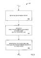
- FIG. 6is a flow chart of one embodiment of a method for authenticating one or more devices connected to a telephone line.
- FIG. 1is a diagram of a broadband signal distribution system 100 wherein a multiple services operator (MSO) 102 provides a broadband signal to a dwelling 104 of a subscriber via a broadband network 106 .
- a multiple service operator (MSO)is a service provider that provides multiple services to subscribers.
- the multiple servicesmay include, for example, one or more “basic” services and the one or more conditional access services.
- the MSOmay provide the basic services for a set fee (e.g., a set monthly fee), and provide each of the conditional access services for an additional fee (e.g., an additional monthly fee).
- Examples of basic services the MSO 102 may provideinclude television programming, data transmission services, and interactive services.
- Each conditional access serviceis typically provided via a conditional access signal that is scrambled and/or encrypted (i.e., encoded) as described above.
- conditional access services the MSO 102may provide include premium television channels and special broadcasts (e.g., sporting events, pay-per-view movies, etc.), data transmission services, interactive services, digital radio broadcasts, digital data broadcasts, and interactive services.
- the broadband signalis used to convey the multiple services to the dwelling 104 .
- a typical broadband signalincludes multiple signals conveying the multiple services.
- the broadband signalmay also include one or more conditional access signals conveying the one or more conditional access services.
- the broadband signalmay be, for example, frequency division multiplexed and/or time division multiplexed to convey the multiple signals to the dwelling 104 .
- the broadband network 106may include, for example, a cable network, a satellite network, and/or a terrestrial broadcast network.
- a cable networkthe broadband signal is typically distributed via coaxial cable.
- the broadband signalis transmitted to a satellite via an uplink satellite dish antenna, and received by a downlink satellite dish antenna.
- the downlink satellite dish antennamay be, for example, attached to, or adjacent to, the dwelling 104 .
- the broadband signalis transmitted via a transmitting antenna, and received by a receiving antenna.
- the receiving antennamay be, for example, attached to, or adjacent to, the dwelling 104 .
- multiple integrated receiver decoders (IRDs) 108 A– 108 Cexist within the dwelling 104 , and receive the broadband signal.
- an integrated receiver decoder (IRD)is a device adapted to receive a broadband signal generally including a conditional access signal, and may be configurable to descramble or decrypt any conditional access signals.
- the IRDs 108 A– 108 Care referred to below individually and interchangeably as IRD 108 and collectively as IRDs 108 .
- the IRDs 108are connected to a telephone line 110 within the dwelling 104 , along with a telephone 112 .
- the telephone line 110is connected to a public switched telephone network (PSTN) 114 .
- PSTNpublic switched telephone network
- the MSO 102is also connected to the PSTN 114 .
- each IRD 108includes a modulator-demodulator (modem) for communicating with the MSO 102 via the PSTN 114 . This is typical of modem IRDs to facilitate periodic transfers of service usage information from the IRDs 108 to the MSO 102 for billing or other purposes.
- modemmodulator-demodulator
- FIG. 2is a diagram of one embodiment of an exemplary one of the IRDs 108 of FIG. 1 .
- the IRD 108includes a modulator-demodulator (modem) 200 , a central processing unit (CPU) 202 , and a memory 204 .
- the modem 200is connected to the telephone line 110 of FIG. 1 , and is used to transmit and receive signals via the telephone line 110 .
- the CPU 202is coupled to the memory 204 and the modem 200 . As shown in FIG. 2 , the memory 204 is used to store software 206 including program instructions and data. The CPU 202 is configured to control the modem 200 while executing program instructions of the software 206 .
- the CPU 202uses the modem 200 to periodically: (i) detect and authenticate other IRDs connected to the telephone line 110 and within the dwelling 104 via the telephone line 110 , and/or (ii) be detected and authenticated by another IRD connected to the telephone line 110 and within the dwelling 104 via the telephone line 110 .
- a single one of the IRDs 108 in FIG. 1may be responsible for detecting and/or authenticating all of the other IRDs 108 connected to the telephone line 110 within the dwelling 104 .
- the IRD 108 Amay be responsible for detecting and authenticating the IRDs 108 B and 108 C connected to the telephone line 110 within the dwelling 104 .
- the IRD 108 Adetects and authenticates the IRDs 108 B and 108 C, and the IRDs 108 B and 108 C are detected and authenticated by the IRD 108 A.
- each of the IRDs 108may be responsible for detecting and/or authenticating all of the other IRDs 108 connected to the telephone line 110 within the dwelling 104 .
- the IRD 108 Amay be responsible for detecting and authenticating the IRDs 108 B and 108 C
- the IRD 108 Bmay be responsible for detecting and authenticating the IRDs 108 A and 108 C
- the IRD 108 Cmay be responsible for detecting and authenticating the IRDs 108 A and 108 B.
- each of the IRDs 108is detecting and authenticating other IRDs 108 at some times, and being detected and authenticated by other IRDs 108 at other times.
- the detection and authentication status of the IRDs 108may be periodically reported back to the MSO 102 via the telephone line 110 as a part of the service usage information.
- FIG. 3is a diagram of one embodiment of the software 206 of FIG. 2 .
- the software 206includes an IRD detection routine 300 , an IRD authentication routine 302 , a collision detection routine 304 , and an off-hook detection routine 306 .
- the IRD detection routine 300detects the presence of other IRDs 108 coupled to the telephone line 110 in the subscriber dwelling 104 .
- the IRD authentication routine 302authenticates any IRDs 108 detected in the dwelling 104 .
- the detection and authentication routines 300 and 302may utilize DTMF codes or other means of communication via the telephone line 110 .
- a collision detection routine 304handles the potential collision of communications on the shared telephone line 110 .
- the off-hook detection routine 306detects whether a phone on the telephone line 110 in the dwelling 104 has been picked-up for usage in order to suspend, relay, or cease communications between the IRDs 108 .
- the function and purposes of these routinesare further described herein. It should be recognized, however, that each of these routines and their functions could be implemented in either software or hardware modules or routines.
- FIG. 4is a flow chart of one embodiment of a first method 400 for detecting one or more devices (e.g., IRDs 108 of FIG. 1 ) connected to a telephone line (e.g., the telephone line 110 of FIG. 1 ).
- the first method 400may be carried out by a device (e.g., an IRD) connected to the telephone line and configured to detect one or more other devices (e.g., other IRDs) connected to the telephone line.
- the method 400may be embodied within the IRD detection routine 300 of FIG. 3 , and implemented by the CPU 202 of FIG. 2 via the modem 200 of FIG. 2 when executing program instructions of the IRD detection routine 300 .
- an off-hook stateis initiated.
- the off-hook stateis normally used to signal the PSTN 114 of FIG. 1 that a user wants to use the telephone line 110 of FIG. 1 .
- the telephone line 110includes a pair of wires referred to as a “loop.”
- a central office of the PSTN 114couples an electrical voltage across the pair of wires and monitors electrical current flow through the loop.
- the usercloses a switch within a communication device connected to the telephone line 110 (e.g., by lifting a handset of the telephone 112 ), thereby initiating an off-hook state of the communication device.
- This switch closurecauses electrical current to flow through the loop, signaling the central office that the user wants to use the telephone line 110 .
- the central officeUpon detecting the electrical current flowing through the loop, the central office prepares to store dialed digits and drives a dial tone signal across the pair of wires of the telephone line 110 .
- a first predetermined sequence of dual-tone multifrequency (DTMF) codesis driven on the telephone line.
- Modern telephonesinclude keypads with numbered buttons. The act of “dialing” a telephone number involves pressing the numbered buttons of the keypad in sequence. Pressing a button of the keypad causes a DTMF signal or code to be driven on the telephone line 110 of FIG. 1 .
- the DTMF codeincludes two non-harmonic tones.
- the DTMF codeis received by switching equipment in the central office of the PSTN 114 of FIG. 1 and decoded. The sequence of dialed numbers is used to determine which telephone subscriber is to receive the telephone call.
- the first predetermined sequence of DTMF codesmay be, for example, a telephone number.
- the telephone numbermay be, for example, a toll-free telephone number of the MSO 102 of FIG. 1 , or a local access number of the MSO 102 . This may be advantageous in the event the MSO 102 wants to monitor or record the results of IRD detection operations.
- the first predetermined sequence of DTMF codesmay be a telephone number that will not result in a complete connection via the PSTN 114 of FIG. 1 . For example, in the United States, the block of numbers between 555-0100 and 555-0199 will not result in a connection via the PSTN 114 of FIG. 1
- the telephone lineis monitored for a second predetermined sequence of DTMF codes. Reception of the second predetermined sequence of DTMF codes indicates another device is connected to the telephone line, is operational, and is ready to communicate.
- Driving the first predetermined sequence of DTMF codes and/or the second predetermined sequence of DTMF codes on the telephone linemay result in a telephone number being dialed.
- the central office of the PSTN 114may drive one or more special information tones and/or a verbal error message on the telephone line 110 of FIG. 1 .
- Such special information tones and verbal error messagesrepresent noise signals of substantial amplitude during the operation 406 .
- the operation 406may be reliably carried out in the presence of any special information tones and/or verbal error messages generated remotely by the PSTN 114 .
- any device connected to the telephone linee.g., the telephone line 110 of FIG. 1
- a device carrying out the operation 402may suspend, delay, or cease operation, and may check again after a predetermined time to see if any device connected to the telephone line is in an off-hook state. If not, the operation 402 may be performed.
- FIG. 5is a flow chart of one embodiment of a second method 500 for detecting a device (e.g., an IRD 108 of FIG. 1 ) connected to a telephone line (e.g., the telephone line 110 of FIG. 1 ).
- the second method 500may be carried out by a device (e.g., an IRD) connected to the telephone line and configured to be detected by other devices (e.g., other IRDs) connected to the telephone line.
- the method 500may be embodied within the IRD detection routine 300 of FIG. 3 , with or without the method 400 of FIG. 4 , and implemented by the CPU 202 of FIG. 2 via the modem 200 of FIG. 2 when executing program instructions of the IRD detection routine 300 .
- an off-hook state of any device connected to the telephone lineis detected.
- the telephone lineis monitored for the first predetermined sequence of dual tone multi-frequency (DTMF) codes described above during an operation 504 .
- DTMFdual tone multi-frequency
- the second predetermined sequence of DTMF codes described aboveis driven on the telephone line.
- the driving of the second predetermined sequence of DTMF codes on the telephone line by a deviceindicates the device is connected to the telephone line, is operational, and is ready to communicate.
- FIG. 6is a flow chart of one embodiment of a method 600 for authenticating one or more devices (e.g., one or more of the IRDs 108 of FIG. 1 ) connected to a telephone line (e.g., the telephone line 110 of FIG. 1 ).
- the method 600may be carried out by a device (e.g., an IRD) connected to the telephone line and configured to detect and authenticate other devices (e.g., other IRDs) connected to the telephone line.
- the method 600may be embodied within the IRD authentication routine 302 of FIG. 3 , and implemented by the CPU 202 of FIG. 2 via the modem 200 of FIG. 2 when executing program instructions of the IRD authentication routine 302 .
- entitlement information corresponding to each of the one or more devices connected to the telephone lineis received via a broadband signal.
- entitlement informationis conveyed via messages inserted into conditional access signals by conditional access encoding equipment.
- Such messagestypically include entitlement management messages (EMMs) and entitlement control messages (ECMs).
- EMMsare used to modify entitlement information (e.g., a list of conditional access services a subscriber is entitled to access) stored in an IRD.
- each subscriber IRD having a smart cardis expected to be located within the subscriber's dwelling at all times.
- each IRDmay be assigned a unique identification string or number.
- each of the IRDs 108 of FIG. 1may be expected to be located within the dwelling 104 of FIG. 1 at all times, and may be assigned a unique identification string or number.
- the unique identification strings or numbersmay be assigned during IRD manufacture, or arbitrarily by the MSO 102 of FIG. 1 .
- One or more EMMs inserted into the conditional access signalmay be modified to include a list of the unique identification strings or numbers assigned to IRDs expected to be located in a particular dwelling.
- the entitlement informationis used to authenticate each of the one or more devices via the telephone line.
- authenticationinvolves a first party and a second party.
- the second partyprovides information to the first party to prove the identity of the second party.
- a modem routinemay be initiated with each of the one or more devices in sequence.
- a commandmay be issued to provide the unique identification string or number assigned to the device.
- a received identification string or numbermay be compared to a list of identification strings or numbers of devices expected to be connected to the telephone line.
- the modem routinemay be carried out using a signal modulation technique such as frequency shift keying (FSK), using DTMF tones, or other communication signals.
- FSKfrequency shift keying
- a “master” one of the IRDs 108detects and authenticates the other “slave” IRDs 108 within the dwelling 104 of FIG. 1 via the telephone line 110 .
- the method 400 of FIG. 4may be embodied within the IRD detection routine 302 ( FIG. 3 ) of the master IRD 108
- the method 600 of FIG. 6may be embodied within the IRD authentication routine 304 ( FIG. 3 ) of the master IRD 108
- the method 500 of FIG. 5may be embodied within the IRD detection routine 302 ( FIG. 3 ) of each of the slave IRDs 108 .
- the master IRDmay periodically detect and authenticate the slave IRDs 108 via the telephone line 110 of FIG. 1 .
- the master IRD 108may initiate the IRD authentication routine 304 .
- the master IRD 108may initiate a modem routine with each of the slave IRDs 108 in sequence.
- the master IRD 108may issue a command to a slave IRD 108 to provide the identification string or number assigned to the slave IRD 108 .
- the master IRD 108may compare the identification string or number received from the slave IRD 108 to a list of identification strings or numbers of IRDs expected to be located within the dwelling 104 of FIG. 1 and connected to the telephone line 110 .
- the master IRD 108may issue a terminate command to the slave IRD 108 , and the slave IRD 108 may transmit an acknowledgment response back to the master IRD 108 . Following transmission of the acknowledgment response, the slave IRD 108 may enter an inactive state with regard to any further communication during the current authentication session.
- each of the slave IRDs 108 expected to be located within the dwelling 104 of FIG. 1 and connected to the telephone line 110is detected and returns a correct identification string or number, the master IRD 108 remains in a fully functional state.
- the master IRD 108enters a state of minimal functionality.
- the subscribermay be notified that one or more expected slave IRDs were not detected, or returned an incorrect identification string or number.
- the subscribermay be provided with instructions for solving the problem and/or reinitiating the IRD detection routine 302 and the IRD authentication routine 304 .
- the master IRD 108may include a counter associated with the detection method 400 of FIG. 4 and the authorization method 600 of FIG. 6 .
- the countermay be initialized to zero each time all of the slave IRDs 108 expected to be located within the dwelling 104 of FIG. 1 are detected and authenticated. Each time one or more of the slave IRDs 108 is not detected and/or authenticated, the counter may be incremented. If the counter within the master IRD 108 reaches a specific value, the master IRD 108 may enter the state of minimal functionality described above.
- each of the IRDs 108 in FIG. 1may include a pseudo-random number generator.
- Each pseudo-random number generatormay be configured to generate a different pseudo-random number, and may use a last pseudo-random number as a seed in generating a next pseudo-random number.
- Each pseudo-random number generated by an IRD 108may be stored in a non-volatile memory of the IRD 108 to prevent loss when power to the IRD 108 is interrupted.
- One or more EMMs inserted into the conditional access signalmay be modified to include a list of pseudo-random numbers expectedly generated by IRDs expectedly located in a particular dwelling.
- the master IRD 108may issue a command to a slave IRD 108 to generate a (next) pseudo-random number, and drive the pseudo-random number on the telephone line 110 of FIG. 1 .
- the master IRD 108may compare the pseudo-random number received from the slave IRD 108 to the list of pseudo-random numbers expected to be returned by IRDs located within the dwelling 104 of FIG. 1 and connected to the telephone line 110 .
- the software 206includes a collision detection routine 304 .
- the master IRD 108detects the slave IRDs 108 via the method 400 of FIG. 4 , and drives the first predetermined sequence of dual tone multi-frequency (DTMF) codes on the telephone line during the operation 404 , all of the slave IRDs 108 may attempt to respond at the same time.
- the collision detection routine 304may be used to effect communication with each of the slave IRDs 108 in sequence.
- the CPU 202 of FIG. 2may use the modem 200 of FIG. 2 to monitor the telephone line 110 for the presence of a signal prior to transmitting each data unit (e.g., character).
- a signal detected on the telephone line 110may indicate a collision, and the CPU 202 may stop transmitting and wait a random length of time before attempting to transmit again.
- each slave IRD 108 detecting a collisionexpectedly waits a different amount of time, sequential communications with each of the slave IRDs 108 is expectedly achieved.
- any multidrop communication protocolthat does not require a slave IRE 108 to know how many IRDs 108 exist within the dwelling 104 may be used to determine which of the slave IRDs 108 establishes a connection with the master IRD 108 .
- the software 206 of FIG. 3also includes an off-hook detection routine 306 . While executing the program instructions of the off-hook detection routine 306 , the CPU 202 of FIG. 2 may use the modem 200 of FIG. 2 to monitor the telephone line 110 for an indication of an off-hook state in any device coupled to the telephone line 110 .
- the off-hook detection routine 306may be used to carry out the operation 502 of the method 500 of FIG. 5 , and to detect an off-hook condition in any device coupled to the telephone line 110 prior to and/or during the detecting method 400 of FIG. 4 , and during the operation 604 of the authentication method 600 of FIG. 6 .
- the master IRD 108may then suspend, delay or terminate the current operation and reinitiate the detecting method 400 of FIG. 4 and/or the operation 604 of the authentication method 600 of FIG. 6 at a later time.
- Each IRD 108 in FIG. 1may include a counter associated with the off-hook detection routine 306 , the detection method 400 of FIG. 4 , and the authorization method 600 of FIG. 6 .
- the countermay be initialized to zero each time all of the IRDs expected to be located within a particular dwelling are detected and authenticated. Each time all of the IRDs expected to be located within a particular dwelling are not detected and/or authenticated, or the detection and/or authorization is terminated due to an off-hook state of another device, the counter may be incremented. If the counter within an IRD 108 reaches a specific value, the IRD 108 may enter the state of minimal functionality described above.
- the detection method 400 of FIG. 4 and the detection method 500 of FIG. 5may be embodied within the IRD detection routine 302 ( FIG. 3 ) of the each of the IRD 108 s, and the authentication method 600 of FIG. 6 may be embodied within the IRD authentication routine 304 ( FIG. 3 ) of each of the IRDs 108 .
- Each of the IRDs 108may periodically detect and authenticate the other IRDs 108 , at different times, via the telephone line 110 of FIG. 1 .
- an initiating IRD 108may initiate the IRD authentication routine 304 .
- the initiating IRD 108may initiate a modem routine with each of the other IRDs 108 (e.g., with each of the non-initiating IRDs 108 ) in sequence.
- the initiating IRD 108may issue a command to a non-initiating IRD 108 to provide the identification string or number assigned to the non-initiating IRD 108 .
- the initiating IRD 108may compare the identification string or number received from the non-initiating IRD 108 to a list of identification strings or numbers of IRDs expected to be located within the dwelling 104 of FIG. 1 and connected to the telephone line 110 .
- the initiating IRD 108If each of the non-initiating IRDs 108 expected to be located within the dwelling 104 of FIG. 1 and connected to the telephone line 110 is detected and returns a correct identification string or number, the initiating IRD 108 remains in a fully functional state. On the other hand, if the one or more of the non-initiating IRDs 108 is not detected, or returns an incorrect identification string or number, the initiating IRD 108 enters a state of minimal functionality. When the initiating IRD 108 is in the state of minimal functionality, the subscriber may be notified that one or more expected non-initiating IRDs 108 were not detected, or returned an incorrect identification string or number. The subscriber may be provided with instructions for solving the problem and/or reinitiating the IRD detection routine 302 and the IRD authentication routine 304 .
- the detection methods 400 and 500 and the authentication method 600may be performed late at night when occupants of the dwelling 104 of FIG. 1 are less likely to be using the telephone line 110 of FIG. 1 . It is noted that existing telephone wiring installed within the dwelling 104 of FIG. 1 is advantageously used to provide a communication path between all of the IRDs 108 located within that dwelling 104 . Also, a modem expectedly present in each of the IRDs 108 to convey service information to the MSO 102 of FIG. 1 is advantageously used to carry out the above described detection and authentication methods within the dwelling 104 . As such, detection and authentication of all IRDs within a dwelling is made possible at minimal expense to an MSO, and at no additional cost to the MSO on a per-subscriber basis.
Landscapes
- Engineering & Computer Science (AREA)
- Computer Hardware Design (AREA)
- Computer Security & Cryptography (AREA)
- Computing Systems (AREA)
- General Engineering & Computer Science (AREA)
- Computer Networks & Wireless Communication (AREA)
- Signal Processing (AREA)
- Telephonic Communication Services (AREA)
Abstract
Description
Claims (31)
Priority Applications (1)
| Application Number | Priority Date | Filing Date | Title |
|---|---|---|---|
| US10/254,185US7039169B2 (en) | 2002-09-25 | 2002-09-25 | Detection and authentication of multiple integrated receiver decoders (IRDs) within a subscriber dwelling |
Applications Claiming Priority (1)
| Application Number | Priority Date | Filing Date | Title |
|---|---|---|---|
| US10/254,185US7039169B2 (en) | 2002-09-25 | 2002-09-25 | Detection and authentication of multiple integrated receiver decoders (IRDs) within a subscriber dwelling |
Publications (2)
| Publication Number | Publication Date |
|---|---|
| US20040057565A1 US20040057565A1 (en) | 2004-03-25 |
| US7039169B2true US7039169B2 (en) | 2006-05-02 |
Family
ID=31993283
Family Applications (1)
| Application Number | Title | Priority Date | Filing Date |
|---|---|---|---|
| US10/254,185Expired - LifetimeUS7039169B2 (en) | 2002-09-25 | 2002-09-25 | Detection and authentication of multiple integrated receiver decoders (IRDs) within a subscriber dwelling |
Country Status (1)
| Country | Link |
|---|---|
| US (1) | US7039169B2 (en) |
Cited By (53)
| Publication number | Priority date | Publication date | Assignee | Title |
|---|---|---|---|---|
| US20020154055A1 (en)* | 2001-04-18 | 2002-10-24 | Robert Davis | LAN based satellite antenna/satellite multiswitch |
| US20030192047A1 (en)* | 2002-03-22 | 2003-10-09 | Gaul Michael A. | Exporting data from a digital home communication terminal to a client device |
| US20040060065A1 (en)* | 2002-09-25 | 2004-03-25 | James Thomas H. | Direct broadcast signal distribution methods |
| US20040068747A1 (en)* | 2002-10-02 | 2004-04-08 | Robertson Neil C. | Networked multimedia system |
| US20060041912A1 (en)* | 2004-08-19 | 2006-02-23 | Kevin Kuhns | Method and apparatus for authorizing an additional set-top device in a satellite television network |
| US20060225103A1 (en)* | 2005-04-01 | 2006-10-05 | James Thomas H | Intelligent two-way switching network |
| US20060225102A1 (en)* | 2005-04-01 | 2006-10-05 | James Thomas H | Narrow bandwidth signal delivery system |
| US20060225101A1 (en)* | 2005-04-01 | 2006-10-05 | James Thomas H | Signal injection via power supply |
| US20060225100A1 (en)* | 2005-04-01 | 2006-10-05 | James Thomas H | System architecture for control and signal distribution on coaxial cable |
| US20060225099A1 (en)* | 2005-04-01 | 2006-10-05 | James Thomas H | Backwards-compatible frequency translation module for satellite video delivery |
| US20060259929A1 (en)* | 2005-04-01 | 2006-11-16 | James Thomas H | Automatic level control for incoming signals of different signal strengths |
| US20070089142A1 (en)* | 2005-10-14 | 2007-04-19 | John Norin | Band converter approach to Ka/Ku signal distribution |
| US20070204300A1 (en)* | 2006-02-27 | 2007-08-30 | Markley Jeffrey P | Methods and apparatus for selecting digital interface technology for programming and data delivery |
| US20080016535A1 (en)* | 2005-09-02 | 2008-01-17 | The Directv Group, Inc. | Frequency shift key control in video delivery systems |
| US20080022319A1 (en)* | 2006-06-09 | 2008-01-24 | Hanno Basse | Presentation modes for various format bit streams |
| US20080060021A1 (en)* | 2006-06-16 | 2008-03-06 | Hanno Basse | Digital storage media command and control data indexing |
| US20080163285A1 (en)* | 2006-12-28 | 2008-07-03 | Matsushita Electric Industrial Co., Ltd. | Video receiving system, sub-contract video receiver, video receiving method, program, and recording medium |
| US20100130141A1 (en)* | 2008-11-26 | 2010-05-27 | Echostar Technologies L.L.C. | Account Tracking System |
| US7849486B2 (en) | 2000-11-14 | 2010-12-07 | Russ Samuel H | Networked subscriber television distribution |
| US7870584B2 (en) | 2002-08-02 | 2011-01-11 | Russ Samuel H | Interactive program guide with selectable updating |
| US7876998B2 (en) | 2005-10-05 | 2011-01-25 | Wall William E | DVD playback over multi-room by copying to HDD |
| US7937732B2 (en) | 2005-09-02 | 2011-05-03 | The Directv Group, Inc. | Network fraud prevention via registration and verification |
| US7950038B2 (en) | 2005-04-01 | 2011-05-24 | The Directv Group, Inc. | Transponder tuning and mapping |
| US20110131619A1 (en)* | 2006-02-27 | 2011-06-02 | Hasek Charles A | Methods and apparatus for selecting digital coding/decoding technology for programming and data delivery |
| US7991348B2 (en) | 2005-10-12 | 2011-08-02 | The Directv Group, Inc. | Triple band combining approach to satellite signal distribution |
| US8019275B2 (en) | 2005-10-12 | 2011-09-13 | The Directv Group, Inc. | Band upconverter approach to KA/KU signal distribution |
| US8046806B2 (en) | 2002-10-04 | 2011-10-25 | Wall William E | Multiroom point of deployment module |
| US8094640B2 (en) | 2003-01-15 | 2012-01-10 | Robertson Neil C | Full duplex wideband communications system for a local coaxial network |
| US8127326B2 (en)* | 2000-11-14 | 2012-02-28 | Claussen Paul J | Proximity detection using wireless connectivity in a communications system |
| US8229383B2 (en) | 2009-01-06 | 2012-07-24 | The Directv Group, Inc. | Frequency drift estimation for low cost outdoor unit frequency conversions and system diagnostics |
| US8238813B1 (en) | 2007-08-20 | 2012-08-07 | The Directv Group, Inc. | Computationally efficient design for broadcast satellite single wire and/or direct demod interface |
| US8549565B2 (en) | 2005-04-01 | 2013-10-01 | The Directv Group, Inc. | Power balancing signal combiner |
| US8627385B2 (en) | 2002-10-04 | 2014-01-07 | David B. Davies | Systems and methods for operating a peripheral record playback device in a networked multimedia system |
| US8712318B2 (en) | 2007-05-29 | 2014-04-29 | The Directv Group, Inc. | Integrated multi-sat LNB and frequency translation module |
| US8719875B2 (en) | 2006-11-06 | 2014-05-06 | The Directv Group, Inc. | Satellite television IP bitstream generator receiving unit |
| US8789115B2 (en) | 2005-09-02 | 2014-07-22 | The Directv Group, Inc. | Frequency translation module discovery and configuration |
| US8990869B2 (en) | 2007-09-26 | 2015-03-24 | Time Warner Cable Enterprises Llc | Methods and apparatus for content caching in a video network |
| US9049346B2 (en) | 2006-02-27 | 2015-06-02 | Time Warner Cable Enterprises Llc | Methods and apparatus for selecting digital access technology for programming and data delivery |
| US9438946B2 (en) | 2006-02-27 | 2016-09-06 | Time Warner Cable Enterprises Llc | Methods and apparatus for device capabilities discovery and utilization within a content distribution network |
| US9866609B2 (en) | 2009-06-08 | 2018-01-09 | Time Warner Cable Enterprises Llc | Methods and apparatus for premises content distribution |
| US9883223B2 (en) | 2012-12-14 | 2018-01-30 | Time Warner Cable Enterprises Llc | Apparatus and methods for multimedia coordination |
| US9930387B2 (en) | 2005-02-01 | 2018-03-27 | Time Warner Cable Enterprises Llc | Method and apparatus for network bandwidth conservation |
| US9942618B2 (en) | 2007-10-31 | 2018-04-10 | The Directv Group, Inc. | SMATV headend using IP transport stream input and method for operating the same |
| US9961383B2 (en) | 2008-02-26 | 2018-05-01 | Time Warner Cable Enterprises Llc | Methods and apparatus for business-based network resource allocation |
| US10223713B2 (en) | 2007-09-26 | 2019-03-05 | Time Warner Cable Enterprises Llc | Methods and apparatus for user-based targeted content delivery |
| US10225592B2 (en) | 2007-03-20 | 2019-03-05 | Time Warner Cable Enterprises Llc | Methods and apparatus for content delivery and replacement in a network |
| US10687115B2 (en) | 2016-06-01 | 2020-06-16 | Time Warner Cable Enterprises Llc | Cloud-based digital content recorder apparatus and methods |
| US10911794B2 (en) | 2016-11-09 | 2021-02-02 | Charter Communications Operating, Llc | Apparatus and methods for selective secondary content insertion in a digital network |
| US10939142B2 (en) | 2018-02-27 | 2021-03-02 | Charter Communications Operating, Llc | Apparatus and methods for content storage, distribution and security within a content distribution network |
| US11223860B2 (en) | 2007-10-15 | 2022-01-11 | Time Warner Cable Enterprises Llc | Methods and apparatus for revenue-optimized delivery of content in a network |
| US11496782B2 (en) | 2012-07-10 | 2022-11-08 | Time Warner Cable Enterprises Llc | Apparatus and methods for selective enforcement of secondary content viewing |
| US11722938B2 (en) | 2017-08-04 | 2023-08-08 | Charter Communications Operating, Llc | Switching connections over frequency bands of a wireless network |
| US12436916B2 (en) | 2014-08-05 | 2025-10-07 | Time Warner Cable Enterprises Llc | Apparatus and methods for lightweight transcoding |
Families Citing this family (10)
| Publication number | Priority date | Publication date | Assignee | Title |
|---|---|---|---|---|
| US20090320058A1 (en)* | 2005-04-05 | 2009-12-24 | Thomson Licensing | Multimedia Content Distribution System and Method for Multiple Dwelling Unit |
| US8422982B2 (en)* | 2005-10-03 | 2013-04-16 | Raven Nc Llc | Method and apparatus for DC power management within multi-channel LNBF |
| GB0525995D0 (en)* | 2005-12-21 | 2006-02-01 | Electra Entertainment Ltd | An enhanced interactive television return path |
| US20070281610A1 (en)* | 2006-06-05 | 2007-12-06 | The Directv Group, Inc. | Method and system for providing call-backs from a mobile receiving device |
| US20070280477A1 (en)* | 2006-06-05 | 2007-12-06 | The Directv Group, Inc. | Method and system for providing conditional access authorizations to a mobile receiving device |
| US8107626B2 (en) | 2006-11-22 | 2012-01-31 | The Directv Group, Inc. | Method and system for enabling transfer of content between a storage device and a portable media player device |
| US8875206B2 (en) | 2006-11-22 | 2014-10-28 | The Directv Group, Inc. | Method and system for securely providing content to a portable media player device |
| US7747703B2 (en)* | 2006-11-22 | 2010-06-29 | The Directv Group, Inc. | Method and system for targeted marketing to a portable media player device owner |
| US8793748B2 (en)* | 2007-07-26 | 2014-07-29 | The Directv Group, Inc. | Method and system for controlling communication between a user device and a content delivery network |
| US20090028317A1 (en)* | 2007-07-26 | 2009-01-29 | The Directv Group, Inc. | Method and system for providing callbacks from a user device using an ip network |
Citations (5)
| Publication number | Priority date | Publication date | Assignee | Title |
|---|---|---|---|---|
| US5307411A (en)* | 1991-09-12 | 1994-04-26 | Televerket | Means for identification and exchange of encryption keys |
| US5422939A (en)* | 1993-08-05 | 1995-06-06 | Schlumberger Industries, Inc. | Parallel off-hook detection for both line-available and phone pick-up detection |
| US5748732A (en)* | 1995-02-08 | 1998-05-05 | U.S. Philips Corporation | Pay TV method and device which comprise master and slave decoders |
| WO2000004718A1 (en)* | 1998-07-15 | 2000-01-27 | Canal+ Societe Anonyme | Method and apparatus for secure communication of information between a plurality of digital audiovisual devices |
| US6405369B1 (en)* | 1996-03-18 | 2002-06-11 | News Datacom Limited | Smart card chaining in pay television systems |
- 2002
- 2002-09-25USUS10/254,185patent/US7039169B2/ennot_activeExpired - Lifetime
Patent Citations (5)
| Publication number | Priority date | Publication date | Assignee | Title |
|---|---|---|---|---|
| US5307411A (en)* | 1991-09-12 | 1994-04-26 | Televerket | Means for identification and exchange of encryption keys |
| US5422939A (en)* | 1993-08-05 | 1995-06-06 | Schlumberger Industries, Inc. | Parallel off-hook detection for both line-available and phone pick-up detection |
| US5748732A (en)* | 1995-02-08 | 1998-05-05 | U.S. Philips Corporation | Pay TV method and device which comprise master and slave decoders |
| US6405369B1 (en)* | 1996-03-18 | 2002-06-11 | News Datacom Limited | Smart card chaining in pay television systems |
| WO2000004718A1 (en)* | 1998-07-15 | 2000-01-27 | Canal+ Societe Anonyme | Method and apparatus for secure communication of information between a plurality of digital audiovisual devices |
Cited By (83)
| Publication number | Priority date | Publication date | Assignee | Title |
|---|---|---|---|---|
| US7849486B2 (en) | 2000-11-14 | 2010-12-07 | Russ Samuel H | Networked subscriber television distribution |
| US8127326B2 (en)* | 2000-11-14 | 2012-02-28 | Claussen Paul J | Proximity detection using wireless connectivity in a communications system |
| US8549567B2 (en) | 2000-11-14 | 2013-10-01 | Samuel H. Russ | Media content sharing over a home network |
| US7861272B2 (en) | 2000-11-14 | 2010-12-28 | Russ Samuel H | Networked subscriber television distribution |
| US20020154055A1 (en)* | 2001-04-18 | 2002-10-24 | Robert Davis | LAN based satellite antenna/satellite multiswitch |
| US20030192047A1 (en)* | 2002-03-22 | 2003-10-09 | Gaul Michael A. | Exporting data from a digital home communication terminal to a client device |
| US7870584B2 (en) | 2002-08-02 | 2011-01-11 | Russ Samuel H | Interactive program guide with selectable updating |
| US7954127B2 (en) | 2002-09-25 | 2011-05-31 | The Directv Group, Inc. | Direct broadcast signal distribution methods |
| US20040060065A1 (en)* | 2002-09-25 | 2004-03-25 | James Thomas H. | Direct broadcast signal distribution methods |
| US20040068747A1 (en)* | 2002-10-02 | 2004-04-08 | Robertson Neil C. | Networked multimedia system |
| US7908625B2 (en) | 2002-10-02 | 2011-03-15 | Robertson Neil C | Networked multimedia system |
| US8046806B2 (en) | 2002-10-04 | 2011-10-25 | Wall William E | Multiroom point of deployment module |
| US9762970B2 (en) | 2002-10-04 | 2017-09-12 | Tech 5 | Access of stored video from peer devices in a local network |
| US8966550B2 (en) | 2002-10-04 | 2015-02-24 | Cisco Technology, Inc. | Home communication systems |
| US8627385B2 (en) | 2002-10-04 | 2014-01-07 | David B. Davies | Systems and methods for operating a peripheral record playback device in a networked multimedia system |
| US8094640B2 (en) | 2003-01-15 | 2012-01-10 | Robertson Neil C | Full duplex wideband communications system for a local coaxial network |
| US8230470B2 (en) | 2003-01-15 | 2012-07-24 | Robertson Neil C | Full duplex wideband communications system for a local coaxial network |
| US20060041912A1 (en)* | 2004-08-19 | 2006-02-23 | Kevin Kuhns | Method and apparatus for authorizing an additional set-top device in a satellite television network |
| US9930387B2 (en) | 2005-02-01 | 2018-03-27 | Time Warner Cable Enterprises Llc | Method and apparatus for network bandwidth conservation |
| US7958531B2 (en) | 2005-04-01 | 2011-06-07 | The Directv Group, Inc. | Automatic level control for incoming signals of different signal strengths |
| US7950038B2 (en) | 2005-04-01 | 2011-05-24 | The Directv Group, Inc. | Transponder tuning and mapping |
| US20060225102A1 (en)* | 2005-04-01 | 2006-10-05 | James Thomas H | Narrow bandwidth signal delivery system |
| US7900230B2 (en)* | 2005-04-01 | 2011-03-01 | The Directv Group, Inc. | Intelligent two-way switching network |
| US20060225101A1 (en)* | 2005-04-01 | 2006-10-05 | James Thomas H | Signal injection via power supply |
| US20060225103A1 (en)* | 2005-04-01 | 2006-10-05 | James Thomas H | Intelligent two-way switching network |
| US7945932B2 (en) | 2005-04-01 | 2011-05-17 | The Directv Group, Inc. | Narrow bandwidth signal delivery system |
| US8024759B2 (en) | 2005-04-01 | 2011-09-20 | The Directv Group, Inc. | Backwards-compatible frequency translation module for satellite video delivery |
| US8621525B2 (en) | 2005-04-01 | 2013-12-31 | The Directv Group, Inc. | Signal injection via power supply |
| US8549565B2 (en) | 2005-04-01 | 2013-10-01 | The Directv Group, Inc. | Power balancing signal combiner |
| US20060225100A1 (en)* | 2005-04-01 | 2006-10-05 | James Thomas H | System architecture for control and signal distribution on coaxial cable |
| US7987486B2 (en) | 2005-04-01 | 2011-07-26 | The Directv Group, Inc. | System architecture for control and signal distribution on coaxial cable |
| US20060225099A1 (en)* | 2005-04-01 | 2006-10-05 | James Thomas H | Backwards-compatible frequency translation module for satellite video delivery |
| US20060259929A1 (en)* | 2005-04-01 | 2006-11-16 | James Thomas H | Automatic level control for incoming signals of different signal strengths |
| US7937732B2 (en) | 2005-09-02 | 2011-05-03 | The Directv Group, Inc. | Network fraud prevention via registration and verification |
| US20080016535A1 (en)* | 2005-09-02 | 2008-01-17 | The Directv Group, Inc. | Frequency shift key control in video delivery systems |
| US8789115B2 (en) | 2005-09-02 | 2014-07-22 | The Directv Group, Inc. | Frequency translation module discovery and configuration |
| US8280229B2 (en) | 2005-10-05 | 2012-10-02 | Wall William E | DVD playback over multi-room by copying to HDD |
| US7876998B2 (en) | 2005-10-05 | 2011-01-25 | Wall William E | DVD playback over multi-room by copying to HDD |
| US7991348B2 (en) | 2005-10-12 | 2011-08-02 | The Directv Group, Inc. | Triple band combining approach to satellite signal distribution |
| US8019275B2 (en) | 2005-10-12 | 2011-09-13 | The Directv Group, Inc. | Band upconverter approach to KA/KU signal distribution |
| US20070089142A1 (en)* | 2005-10-14 | 2007-04-19 | John Norin | Band converter approach to Ka/Ku signal distribution |
| US8718100B2 (en) | 2006-02-27 | 2014-05-06 | Time Warner Cable Enterprises Llc | Methods and apparatus for selecting digital interface technology for programming and data delivery |
| US9398336B2 (en) | 2006-02-27 | 2016-07-19 | Time Warner Cable Enterprises Llc | Methods and apparatus for selecting digital interface technology for programming and data delivery |
| US10009652B2 (en) | 2006-02-27 | 2018-06-26 | Time Warner Cable Enterprises Llc | Methods and apparatus for selecting digital access technology for programming and data delivery |
| US10743066B2 (en) | 2006-02-27 | 2020-08-11 | Time Warner Cable Enterprises Llc | Methods and apparatus for selecting digital access technology for programming and data delivery |
| US20070204300A1 (en)* | 2006-02-27 | 2007-08-30 | Markley Jeffrey P | Methods and apparatus for selecting digital interface technology for programming and data delivery |
| US10051302B2 (en) | 2006-02-27 | 2018-08-14 | Time Warner Cable Enterprises Llc | Methods and apparatus for device capabilities discovery and utilization within a content distribution network |
| US9438946B2 (en) | 2006-02-27 | 2016-09-06 | Time Warner Cable Enterprises Llc | Methods and apparatus for device capabilities discovery and utilization within a content distribution network |
| US20110131619A1 (en)* | 2006-02-27 | 2011-06-02 | Hasek Charles A | Methods and apparatus for selecting digital coding/decoding technology for programming and data delivery |
| US9049346B2 (en) | 2006-02-27 | 2015-06-02 | Time Warner Cable Enterprises Llc | Methods and apparatus for selecting digital access technology for programming and data delivery |
| US8804767B2 (en) | 2006-02-27 | 2014-08-12 | Time Warner Cable Enterprises Llc | Methods and apparatus for selecting digital coding/decoding technology for programming and data delivery |
| US20080022319A1 (en)* | 2006-06-09 | 2008-01-24 | Hanno Basse | Presentation modes for various format bit streams |
| US20080060021A1 (en)* | 2006-06-16 | 2008-03-06 | Hanno Basse | Digital storage media command and control data indexing |
| US8719875B2 (en) | 2006-11-06 | 2014-05-06 | The Directv Group, Inc. | Satellite television IP bitstream generator receiving unit |
| US20080163285A1 (en)* | 2006-12-28 | 2008-07-03 | Matsushita Electric Industrial Co., Ltd. | Video receiving system, sub-contract video receiver, video receiving method, program, and recording medium |
| US10225592B2 (en) | 2007-03-20 | 2019-03-05 | Time Warner Cable Enterprises Llc | Methods and apparatus for content delivery and replacement in a network |
| US10863220B2 (en) | 2007-03-20 | 2020-12-08 | Time Warner Cable Enterprises Llc | Methods and apparatus for content delivery and replacement in a network |
| US8712318B2 (en) | 2007-05-29 | 2014-04-29 | The Directv Group, Inc. | Integrated multi-sat LNB and frequency translation module |
| US8238813B1 (en) | 2007-08-20 | 2012-08-07 | The Directv Group, Inc. | Computationally efficient design for broadcast satellite single wire and/or direct demod interface |
| US10810628B2 (en) | 2007-09-26 | 2020-10-20 | Time Warner Cable Enterprises Llc | Methods and apparatus for user-based targeted content delivery |
| US9596489B2 (en) | 2007-09-26 | 2017-03-14 | Time Warner Cable Enterprises Llc | Methods and apparatus for content caching in a video network |
| US8990869B2 (en) | 2007-09-26 | 2015-03-24 | Time Warner Cable Enterprises Llc | Methods and apparatus for content caching in a video network |
| US10223713B2 (en) | 2007-09-26 | 2019-03-05 | Time Warner Cable Enterprises Llc | Methods and apparatus for user-based targeted content delivery |
| US10085047B2 (en) | 2007-09-26 | 2018-09-25 | Time Warner Cable Enterprises Llc | Methods and apparatus for content caching in a video network |
| US11223860B2 (en) | 2007-10-15 | 2022-01-11 | Time Warner Cable Enterprises Llc | Methods and apparatus for revenue-optimized delivery of content in a network |
| US9942618B2 (en) | 2007-10-31 | 2018-04-10 | The Directv Group, Inc. | SMATV headend using IP transport stream input and method for operating the same |
| US9961383B2 (en) | 2008-02-26 | 2018-05-01 | Time Warner Cable Enterprises Llc | Methods and apparatus for business-based network resource allocation |
| US8131206B2 (en)* | 2008-11-26 | 2012-03-06 | Echostar Technologies L.L.C. | Account tracking system |
| US20100130141A1 (en)* | 2008-11-26 | 2010-05-27 | Echostar Technologies L.L.C. | Account Tracking System |
| US8229383B2 (en) | 2009-01-06 | 2012-07-24 | The Directv Group, Inc. | Frequency drift estimation for low cost outdoor unit frequency conversions and system diagnostics |
| US10965727B2 (en) | 2009-06-08 | 2021-03-30 | Time Warner Cable Enterprises Llc | Methods and apparatus for premises content distribution |
| US9866609B2 (en) | 2009-06-08 | 2018-01-09 | Time Warner Cable Enterprises Llc | Methods and apparatus for premises content distribution |
| US11496782B2 (en) | 2012-07-10 | 2022-11-08 | Time Warner Cable Enterprises Llc | Apparatus and methods for selective enforcement of secondary content viewing |
| US9883223B2 (en) | 2012-12-14 | 2018-01-30 | Time Warner Cable Enterprises Llc | Apparatus and methods for multimedia coordination |
| US12436916B2 (en) | 2014-08-05 | 2025-10-07 | Time Warner Cable Enterprises Llc | Apparatus and methods for lightweight transcoding |
| US10687115B2 (en) | 2016-06-01 | 2020-06-16 | Time Warner Cable Enterprises Llc | Cloud-based digital content recorder apparatus and methods |
| US11695994B2 (en) | 2016-06-01 | 2023-07-04 | Time Warner Cable Enterprises Llc | Cloud-based digital content recorder apparatus and methods |
| US10911794B2 (en) | 2016-11-09 | 2021-02-02 | Charter Communications Operating, Llc | Apparatus and methods for selective secondary content insertion in a digital network |
| US11973992B2 (en) | 2016-11-09 | 2024-04-30 | Charter Communications Operating, Llc | Apparatus and methods for selective secondary content insertion in a digital network |
| US11722938B2 (en) | 2017-08-04 | 2023-08-08 | Charter Communications Operating, Llc | Switching connections over frequency bands of a wireless network |
| US10939142B2 (en) | 2018-02-27 | 2021-03-02 | Charter Communications Operating, Llc | Apparatus and methods for content storage, distribution and security within a content distribution network |
| US12081808B2 (en) | 2018-02-27 | 2024-09-03 | Charter Communications Operating, Llc | Apparatus and methods for content storage, distribution and security within a content distribution network |
| US11553217B2 (en) | 2018-02-27 | 2023-01-10 | Charter Communications Operating, Llc | Apparatus and methods for content storage, distribution and security within a content distribution network |
Also Published As
| Publication number | Publication date |
|---|---|
| US20040057565A1 (en) | 2004-03-25 |
Similar Documents
| Publication | Publication Date | Title |
|---|---|---|
| US7039169B2 (en) | Detection and authentication of multiple integrated receiver decoders (IRDs) within a subscriber dwelling | |
| EP0200310B1 (en) | Direct broadcast satellite signal transmission system | |
| EP0679029B1 (en) | System for cooperating with a satellite transponder | |
| US4916737A (en) | Secure anti-piracy encoded television system and method | |
| US7171553B2 (en) | Method for providing a secure communication between two devices and application of this method | |
| US6427013B1 (en) | Information broadcasting method, receiver, and information processing apparatus | |
| EP1441525B1 (en) | System for receiving broadcast digital data comprising a master digital terminal, and at least one slave digital terminal | |
| JP3742282B2 (en) | Broadcast receiving method, broadcast receiving apparatus, information distribution method, and information distribution apparatus | |
| US5204900A (en) | Coding system for descrambling video | |
| AU776108B2 (en) | Method for operating a conditional access system for broadcast applications | |
| US20050198673A1 (en) | Satellite TV security system | |
| US8503675B2 (en) | Cable television secure communication system for one way restricted | |
| EP0711074B1 (en) | System for the transmission and reception of encoded television signals | |
| FI94008B (en) | Decoder system for a video signal | |
| JPH09154177A (en) | Mobile radio station | |
| US20050071866A1 (en) | System for receiving broadcast digital data comprising a master digital terminal, and at least one slave digital terminal | |
| TR201802831T4 (en) | A system for verifying physical proximity between media content recipients. | |
| US20040030884A1 (en) | System for controlling online and offline and offline access to digital data using a software key server | |
| US20050188398A1 (en) | Process for managing the handling of conditional access data by at least two decoders | |
| CA2556617C (en) | Method for management of data processing with conditional access by means of at least two decoders | |
| EP1624690A1 (en) | Method for transmitting and receiving video signals |
Legal Events
| Date | Code | Title | Description |
|---|---|---|---|
| AS | Assignment | Owner name:LSI LOGIC CORPORATION, CALIFORNIA Free format text:ASSIGNMENT OF ASSIGNORS INTEREST;ASSIGNOR:JONES, M. JEFFREY;REEL/FRAME:013337/0014 Effective date:20020924 | |
| STCF | Information on status: patent grant | Free format text:PATENTED CASE | |
| FEPP | Fee payment procedure | Free format text:PAYOR NUMBER ASSIGNED (ORIGINAL EVENT CODE: ASPN); ENTITY STATUS OF PATENT OWNER: LARGE ENTITY | |
| FPAY | Fee payment | Year of fee payment:4 | |
| FPAY | Fee payment | Year of fee payment:8 | |
| AS | Assignment | Owner name:DEUTSCHE BANK AG NEW YORK BRANCH, AS COLLATERAL AG Free format text:PATENT SECURITY AGREEMENT;ASSIGNORS:LSI CORPORATION;AGERE SYSTEMS LLC;REEL/FRAME:032856/0031 Effective date:20140506 | |
| AS | Assignment | Owner name:LSI CORPORATION, CALIFORNIA Free format text:CHANGE OF NAME;ASSIGNOR:LSI LOGIC CORPORATION;REEL/FRAME:033102/0270 Effective date:20070406 | |
| AS | Assignment | Owner name:AVAGO TECHNOLOGIES GENERAL IP (SINGAPORE) PTE. LTD Free format text:ASSIGNMENT OF ASSIGNORS INTEREST;ASSIGNOR:LSI CORPORATION;REEL/FRAME:035390/0388 Effective date:20140814 | |
| AS | Assignment | Owner name:AGERE SYSTEMS LLC, PENNSYLVANIA Free format text:TERMINATION AND RELEASE OF SECURITY INTEREST IN PATENT RIGHTS (RELEASES RF 032856-0031);ASSIGNOR:DEUTSCHE BANK AG NEW YORK BRANCH, AS COLLATERAL AGENT;REEL/FRAME:037684/0039 Effective date:20160201 Owner name:LSI CORPORATION, CALIFORNIA Free format text:TERMINATION AND RELEASE OF SECURITY INTEREST IN PATENT RIGHTS (RELEASES RF 032856-0031);ASSIGNOR:DEUTSCHE BANK AG NEW YORK BRANCH, AS COLLATERAL AGENT;REEL/FRAME:037684/0039 Effective date:20160201 | |
| AS | Assignment | Owner name:BANK OF AMERICA, N.A., AS COLLATERAL AGENT, NORTH CAROLINA Free format text:PATENT SECURITY AGREEMENT;ASSIGNOR:AVAGO TECHNOLOGIES GENERAL IP (SINGAPORE) PTE. LTD.;REEL/FRAME:037808/0001 Effective date:20160201 Owner name:BANK OF AMERICA, N.A., AS COLLATERAL AGENT, NORTH Free format text:PATENT SECURITY AGREEMENT;ASSIGNOR:AVAGO TECHNOLOGIES GENERAL IP (SINGAPORE) PTE. LTD.;REEL/FRAME:037808/0001 Effective date:20160201 | |
| AS | Assignment | Owner name:AVAGO TECHNOLOGIES GENERAL IP (SINGAPORE) PTE. LTD., SINGAPORE Free format text:TERMINATION AND RELEASE OF SECURITY INTEREST IN PATENTS;ASSIGNOR:BANK OF AMERICA, N.A., AS COLLATERAL AGENT;REEL/FRAME:041710/0001 Effective date:20170119 Owner name:AVAGO TECHNOLOGIES GENERAL IP (SINGAPORE) PTE. LTD Free format text:TERMINATION AND RELEASE OF SECURITY INTEREST IN PATENTS;ASSIGNOR:BANK OF AMERICA, N.A., AS COLLATERAL AGENT;REEL/FRAME:041710/0001 Effective date:20170119 | |
| MAFP | Maintenance fee payment | Free format text:PAYMENT OF MAINTENANCE FEE, 12TH YEAR, LARGE ENTITY (ORIGINAL EVENT CODE: M1553) Year of fee payment:12 | |
| AS | Assignment | Owner name:AVAGO TECHNOLOGIES INTERNATIONAL SALES PTE. LIMITE Free format text:MERGER;ASSIGNOR:AVAGO TECHNOLOGIES GENERAL IP (SINGAPORE) PTE. LTD.;REEL/FRAME:047196/0097 Effective date:20180509 | |
| AS | Assignment | Owner name:AVAGO TECHNOLOGIES INTERNATIONAL SALES PTE. LIMITE Free format text:CORRECTIVE ASSIGNMENT TO CORRECT THE EXECUTION DATE PREVIOUSLY RECORDED AT REEL: 047196 FRAME: 0097. ASSIGNOR(S) HEREBY CONFIRMS THE MERGER;ASSIGNOR:AVAGO TECHNOLOGIES GENERAL IP (SINGAPORE) PTE. LTD.;REEL/FRAME:048555/0510 Effective date:20180905 |