US7038959B2 - MRAM sense amplifier having a precharge circuit and method for sensing - Google Patents
MRAM sense amplifier having a precharge circuit and method for sensingDownload PDFInfo
- Publication number
- US7038959B2 US7038959B2US10/943,579US94357904AUS7038959B2US 7038959 B2US7038959 B2US 7038959B2US 94357904 AUS94357904 AUS 94357904AUS 7038959 B2US7038959 B2US 7038959B2
- Authority
- US
- United States
- Prior art keywords
- sense amplifier
- coupled
- terminal
- circuit
- current
- Prior art date
- Legal status (The legal status is an assumption and is not a legal conclusion. Google has not performed a legal analysis and makes no representation as to the accuracy of the status listed.)
- Expired - Lifetime, expires
Links
Images


Classifications
- G—PHYSICS
- G11—INFORMATION STORAGE
- G11C—STATIC STORES
- G11C7/00—Arrangements for writing information into, or reading information out from, a digital store
- G11C7/06—Sense amplifiers; Associated circuits, e.g. timing or triggering circuits
- G11C7/062—Differential amplifiers of non-latching type, e.g. comparators, long-tailed pairs
- G—PHYSICS
- G11—INFORMATION STORAGE
- G11C—STATIC STORES
- G11C11/00—Digital stores characterised by the use of particular electric or magnetic storage elements; Storage elements therefor
- G11C11/02—Digital stores characterised by the use of particular electric or magnetic storage elements; Storage elements therefor using magnetic elements
- G11C11/14—Digital stores characterised by the use of particular electric or magnetic storage elements; Storage elements therefor using magnetic elements using thin-film elements
- G11C11/15—Digital stores characterised by the use of particular electric or magnetic storage elements; Storage elements therefor using magnetic elements using thin-film elements using multiple magnetic layers
- G—PHYSICS
- G11—INFORMATION STORAGE
- G11C—STATIC STORES
- G11C11/00—Digital stores characterised by the use of particular electric or magnetic storage elements; Storage elements therefor
- G11C11/02—Digital stores characterised by the use of particular electric or magnetic storage elements; Storage elements therefor using magnetic elements
- G11C11/16—Digital stores characterised by the use of particular electric or magnetic storage elements; Storage elements therefor using magnetic elements using elements in which the storage effect is based on magnetic spin effect
- G—PHYSICS
- G11—INFORMATION STORAGE
- G11C—STATIC STORES
- G11C5/00—Details of stores covered by group G11C11/00
- G11C5/14—Power supply arrangements, e.g. power down, chip selection or deselection, layout of wirings or power grids, or multiple supply levels
- G—PHYSICS
- G11—INFORMATION STORAGE
- G11C—STATIC STORES
- G11C7/00—Arrangements for writing information into, or reading information out from, a digital store
- G11C7/06—Sense amplifiers; Associated circuits, e.g. timing or triggering circuits
Definitions
- This inventionrelates to Magnetoresistive Random Access Memories (MRAMs), and more particularly to a precharge and equalization circuit for an MRAM sense amplifier and method for sensing.
- MRAMsMagnetoresistive Random Access Memories
- Non-volatile memory devicessuch as FLASH memories
- FLASHis a major non-volatile memory device in use today. Disadvantages of FLASH memory include high voltage requirements and slow program and erase times. Also, FLASH memory has a poor write endurance of 10 4 –10 6 cycles before memory failure. In addition, to maintain reasonable data retention, the scaling of the gate oxide is restricted by the tunneling barrier seen by the electrons. Hence, FLASH memory is limited in the dimensions to which it can be scaled.
- MRAMmagnetoresistive RAM
- Storing datais accomplished by applying magnetic fields and causing a magnetic material in a MRAM device to be magnetized into either of two possible memory states. Reading data stored in the memory is accomplished by sensing differences in tunnel junction resistance in the MRAM cells between the two states. Typically, the stored state of a memory cell can be determined by comparing the cell state to that of a reference cell. However, the difference in resistance between a high state and a low state can be very small, and provide a worst case current difference of 0.5 micro amperes or less, requiring a sense amplifier with high sensitivity. Also, the sense amplifier should provide for a fast read operation. Therefore, there is a need for a sense amplifier with small signal detection capability and provides for a fast read operation in a MRAM.
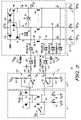
- FIG. 1illustrates, in schematic diagram form, a prior art MRAM sense amplifier.
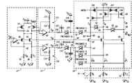
- FIG. 2illustrates, in schematic diagram form, a MRAM sense amplifier in accordance with one embodiment of the present invention.
- FIG. 3is a timing diagram of various signals useful for understanding a read operation of the sense amplifier of FIG. 2 .
- the present inventionprovides a sense amplifier and method for sensing a MRAM cell.
- the sense amplifierincludes a precharge circuit that has an operational amplifier.
- the operational amplifierincludes a voltage divider in its feedback path to control the amount of charge stored on a capacitor.
- the charge stored on the capacitoris used to precharge the sense amplifier.
- a reference circuitdefines a precharge voltage to which the sense amplifier is charged.
- FIG. 1illustrates, in schematic diagram form, a prior art MRAM sense amplifier 10 .
- the MRAM sense amplifier 10includes a reference circuit 12 , a precharge circuit 13 , and a sense circuit 14 .
- the reference circuit 12includes operational amplifier 20 , P-channel transistors 22 and 32 , N-channel transistors 26 and 34 , and reference cells 30 and 36 . Resistance values of reference cells 30 and 36 are represented in FIG. 1 by resistances R H1 and R L1 , respectively.
- the precharge circuit 13includes operational amplifiers 40 and 42 .
- the sense circuit 14includes transmission gates 50 , 80 , 81 , 82 , 83 , and 85 , P-channel transistors 44 , 60 , 66 , 106 , 107 , and 108 , and N-channel common gate transistors 52 , 62 , and 68 .
- An array portion 16includes memory cells 77 , 78 , and 79 .
- the resistance values of memory cells 77 , 78 , and 79are represented in FIG. 1 by resistances R B , R H2 , and R L2 , respectively.
- P-channel transistors 44 , 60 , and 66are coupled to provide a current mirror circuit for sense circuit 14 .
- P-channel transistors 106 , 107 , and 108are coupled to provide an enable circuit for sense circuit 14 .
- the precharge circuit 13is coupled to the sense circuit 14 using conductors 97 , 98 , and 99 .
- sense circuitssimilar the sense circuit 14 .
- only one reference circuit 12 and only one precharge circuit 13are implemented on an integrated circuit to provide a precharge voltage to all of the sense circuits. Note that, in another embodiment, more than one reference circuit 12 and/or precharge circuit 13 may be desirable.
- a parasitic resistance and capacitance of the conductorsmay become significant, as represented by the resistors 100 and 102 and by the capacitors 101 and 103 coupled to conductors 97 and 99 (drawn with dashed lines to show they are parasitic).
- decoupling capacitors 104 and 105are coupled to the conductors 97 and 99 .
- the P-channel transistor 22has a first current electrode (source/drain) coupled to a power supply voltage terminal labeled “V DD ”, and a control electrode (gate) and a second current electrode (source/drain) coupled together at a node 24 .
- the transistorsare implemented using complementary metal-oxide semiconductor (CMOS) technology. In other embodiments, the transistors may be implemented using a different technology.
- the P-channel transistor 32has a source coupled to V DD , and a gate and drain coupled to the gate and drain of P-channel transistor 22 at the node 24 .
- the N-channel transistors 26 and 34have drains coupled to the node 24 , gates coupled together, and sources coupled to a node 28 .
- the operational amplifier 20has a first, non-inverting, input coupled to receive a reference voltage labeled “V REF ”, a second, inverting, input coupled to the node 28 , and an output for providing a voltage labeled “V B2 ” to the gates of transistors 26 and 34 .
- the reference cell 30has a first terminal coupled to the node 28 , and a second terminal coupled to a power supply voltage terminal labeled “V SS ”.
- the reference cell 36has a first terminal coupled to the node 28 , and a second terminal coupled to V SS .
- the operational amplifier 40has a first, non-inverting, input coupled to the node 24 , and a second, inverting, input coupled to an output of operational amplifier 40 .
- the output of amplifier 40is for providing a precharge voltage labeled “V B1 ” to the conductor 97 .
- the operational amplifier 42has a first, non-inverting, input coupled to the node 28 , and a second, inverting, input coupled to the output of operational amplifier 42 .
- the output of amplifier 42is for providing a precharge voltage labeled “V B3 ” to the conductor 99 .
- the P-channel transistor 106has a source coupled to V DD , a gate, and a drain coupled to a node 48 .
- the P-channel transistor 107has a source coupled to V DD , a gate, and a drain coupled to a node 46 .
- the P-channel transistor 108has a source coupled to V DD , a gate, and a drain coupled to a node 84 .
- the nodes 46 , 48 , and 84have capacitances associated with them labeled “C M ” “C O ”, and “C OR ”, respectively.
- the gates of the transistors 106 , 107 , and 108receive a sense amplifier enable signal labeled “AMPEN”.
- P-channel transistor 44 , N-channel transistor 52 , and memory cell 77provide a first current path of the sense circuit 14 for conducting a current labeled “I B ” through memory cell 77 .
- P-channel transistor 60 , N-channel transistor 62 , and reference cell 78provide a second current path of the sense circuit 14 for conducting a reference current labeled “I H ” through reference cell 78 .
- P-channel transistor 66 , N-channel transistor 68 , and reference cell 79provide a third current path of the sense circuit 14 for conducting a reference current labeled “I L ” through reference cell 79 .
- P-channel transistor 44has a source coupled to V DD , a gate coupled to the node 46 , and a drain coupled to the node 48 .
- a memory cell output voltage labeled “OUT”is provided at node 48 .
- N-channel transistor 52has a drain coupled to the node 48 , a gate coupled to the conductor 98 , and a source coupled to a node 54 .
- Memory cell 77is illustrated as a resistor and has a first terminal coupled to the node 54 , and a second terminal coupled to V SS .
- FIG. 1One skilled in the art will recognize that there would be other circuit elements in the current paths that are not illustrated in FIG. 1 , such as for example, column decoding circuits.
- the reference circuit 12 and the precharge circuit 13may include other circuit elements as needed to duplicate the paths of the sensing circuit. The other circuit elements are not needed for purposes of describing the operation of sense circuit 14 and have been omitted for the purpose of brevity.
- P-channel transistor 60has a source coupled to V DD , a gate coupled to the node 46 , and a drain coupled to the node 46 .
- N-channel transistor 62has a drain coupled to the node 46 , a gate coupled to the conductor 98 , and a source coupled to the node 64 .
- the reference cell 78has a first terminal coupled to the node 64 , and a second terminal coupled to V SS .
- P-channel transistor 66has a source coupled to V DD , a gate coupled to the node 46 , and a drain coupled to the node 84 .
- a reference output voltage labeled “OUT REF ”is provided at the node 84 .
- N-channel transistor 68has a drain coupled to the node 84 , a gate coupled to the conductor 98 , and a source coupled to the node 64 .
- the reference cell 79has a first terminal coupled to the node 64 , and a second terminal coupled to V SS .
- reference cells 78 and 79are implemented as normal MRAM cells except that reference cell 78 is programmed to have a resistance R H2 that is equal to the resistance of a normal memory cell that is storing a logic high and reference cell 79 is programmed to have a resistance R L2 that is equal to the resistance of a normal memory cell that is storing a logic low.
- the transmission gate 80has a first terminal coupled to the conductor 97 , a second terminal coupled to the node 46 , and a control terminal for receiving a precharge control signal labeled “PRECHARGE-S”.
- the transmission gates 81 , 82 , and 83each have a first terminal coupled to the conductor 99 .
- a second terminal of transmission gate 81is coupled to the node 54 .
- a second terminal of transmission gate 82is coupled to the node 64 .
- a second terminal of transmission gate 83is coupled to the node 64 .
- Control terminals of each of transmission gates 81 , 82 , and 83receive a precharge control signal labeled “PRECHARGE-B”.
- the transmission gate 50has a first terminal coupled to the node 48 , and a second terminal coupled to the node 46 .
- the transmission gate 85has a first terminal coupled to the node 46 , and a second terminal coupled to the node 84 . Control terminals of the transmission gates 50 and 85 receive an equalization signal labeled “EQ”.
- sense amplifier 10senses a state of a memory cell, represented by resistance 77 , that is programmable to either a high logic state or a low logic state.
- a bit, a high reference, and a low referenceare accessed in sense amplifier 10 by an address and a decoder (not shown).
- the high reference cellis a cell programmed to a distinct high resistance memory state R H2 as represented by resistance 78 .
- the low referenceis a cell programmed to a distinct low resistance memory state R L2 as represented by resistance 79 .
- the bitis an addressed cell whose memory state RB represented by resistance 77 could be either a high (represented by a high resistance state) or a low (represented by a low resistance state).
- pass transistorsmay exist between each of transistors 52 , 62 , and 68 and the associated coupled memory cell so that the resistances 77 , 78 , and 79 each represent a cumulative resistance associated with accessing the associated memory cell.
- pass transistorsmay exist between the resistances 77 , 78 , and 79 and the V SS voltage terminal.
- Reference circuit 12 in combination with precharge circuit 13will generate three specific bias voltages to control sense circuit 14 .
- Sense circuit 14uses a common gate voltage, V B2 , to bias the transistors 52 , 62 , and 68 .
- the biasing of transistors 52 , 62 , and 68places a substantially same bias voltage across resistances R B , R H2 , and R L2 that is close to a transistor threshold below V B2 .
- This biasingestablishes saturated current levels for each of transistors 52 , 62 , and 68 that is represented as I B , I H , and I L .
- I B , I H , and I Lare close to the substantially same bias voltage placed across them divided by the total effective resistance associated with accessing R B , R H2 and R L2 , respectively.
- transistors 60 and 66are connected in a manner that averages I H and I L thereby establishing a current through each of transistors 60 and 66 equal to (I H +I L )/2.
- the biasing of transistors 60 and 66establishes a reference voltage OUT REF at node 84 .
- Connecting the gate of transistor 44 at node 46 to the gates of transistors 60 and 66establishes as a current mirror a saturated current level for transistor 44 that is also equal to (I H +I L )/2.
- the voltage at node 48 , the output (OUT),will then reflect the difference between the saturated current (I H +I L )/2 conducted by transistor 44 and the saturated current I B conducted by transistor 52 .
- the steady state voltage value of the OUT signal at node 48will be lower in potential than the reference voltage OUT REF .
- the steady state voltage value of the OUT signal at node 48will be higher in potential than the reference voltage OUT REF .
- Reference circuit 12receives a reference input voltage, V REF , and uses R H1 and R L1 to provide the illustrated precharge and bias voltages to sense circuit 14 .
- V B2is controlled by operational amplifier 20 to maintain a voltage equal to the V REF input voltage on node 28 .
- Two reference memory cells, R H1 and R L1are coupled to node 28 .
- the R H1 resistanceis a memory cell having a high resistance state and the R L1 resistance is a memory cell having a low resistance state.
- connection of R H1 and R L1 with the inverting input of operational amplifier 20 along with transistors 26 and 34 being sized substantially equal to the size of transistors 52 , 62 , and 68results in the establishment of a voltage V B2 that creates steady state voltages in sense amplifier 14 that are substantially equal to the V REF value.
- the steady state voltagesare the voltages at nodes 28 , 54 , and 64 .
- the voltage V B3 provided by operational amplifier 42is used to precharge nodes 54 and 64 to a value close to their steady state values.
- operational amplifier 40provides a voltage V B1 that is used to precharge nodes 46 , 48 , and 84 in sense amplifier 14 to a value close to their steady state value.
- Reference circuit 12 and precharge circuit 13function to adjust the voltages V B1 , V B2 and V B3 over temperature, supply voltage, and process variations.
- the tracking in voltage values between reference circuit 12 and sense circuit 14is in part due to the intentional device size matching of transistors in reference circuit 12 with transistors in sense circuit 14 and use of reference resistances R H1 and R L1 .
- sense circuit 14When not being used to sense the logic state of memory cells, sense circuit 14 is turned off with the aid of the relatively small P-channel transistors 106 , 107 , and 108 when sense amplifier enable signal AMPEN is a logic low voltage.
- the internal nodes 46 , 48 , and 84are pulled up to VDD. This insures that the sense circuit 14 remains off and that the sensing operation always starts from the same initial condition.
- the enable signal AMPENswitches to a high state enabling the sensing circuit 14 .
- the reference circuit 12 and the precharge circuit 13cause the voltages of nodes 46 , 48 , and 84 to transition to near their steady state common mode voltages.
- the voltages on nodes 54 and 64transition to near their steady state common mode voltages resulting in the sense amplifier being precharged.
- the difference between the resistance of a memory cell, such as memory cell 77 , and the resistance of parallel reference cells, such as reference cells 78 and 79will cause the voltages on nodes 48 and 84 to separate, thus indicating the logic state stored in the cell.
- the resistance of memory cell 77may be compared to only one reference cell having a mid-level resistance.
- the transistorsare sized relatively large to reduce the amount of transistor mismatch.
- the amount of transistor mismatchdecreases with decreasing aspect ratio.
- the use of larger transistorswill also increase the period of time required to precharge the nodes and will increase the required capacitance of decoupling capacitances 104 and 105 to accurately precharge the sense circuit 14 to near steady state common mode voltages.
- FIG. 2illustrates, in schematic diagram form, a MRAM sense amplifier 11 in accordance with one embodiment of the present invention.
- Memory 11differs from memory 10 in that the conductor 97 includes an additional transmission gate 109 controlled by a precharge signal labeled “PRECHARGE-S*”. Also, the conductor 99 includes an additional transmission gate 110 controlled by a precharge signal labeled “PRECHARGE-B*”.
- memory 11differs from memory 10 in that a voltage divider circuit is included in the feedback path of operational amplifiers 40 and 42 .
- a voltage divider 115 associated with amplifier 40includes resistors 111 and 112 .
- the resistor 111has a first terminal coupled to V DD , and a second terminal coupled to the first input of amplifier 40 .
- the resistor 112has a first terminal coupled to the second terminal of resistor 111 , and a second terminal coupled to the output of amplifier 40 .
- a voltage divider 116 associated with amplifier 42includes resistors 113 and 114 .
- the resistor 113has a first terminal coupled to the output of amplifier 42 , and a second terminal coupled to the second input of amplifier 42 .
- the resistor 114has a first terminal coupled to the second terminal of resistor 113 , and a second terminal coupled to V SS .
- precharge signal PRECHARGE-S*is a logical complement of PRECHARGE-S
- precharge signal PRECHARGE-B*is a logical complement of precharge signal PRECHARGE-B.
- reference circuit 12 ′is the same as the operation of reference circuit 12 of FIG. 1 .
- sense circuit 14 ′is the same as the operation of sense circuit 14 . Therefore, the above description of reference circuit 12 and sense circuit 14 also applies to the description of reference circuit 12 ′ and sense circuit 14 ′ and will not be repeated in the description of FIG. 2 .
- the precharge operationas illustrated in the embodiment of FIG. 2 , will be discussed with reference to the precharging of nodes 46 , 48 , and 84 .
- the precharge operation of nodes 54 and 64is similar.
- FIG. 3is a timing diagram of various signals useful for understanding a read operation of the sense amplifier of FIG. 2 .
- the precharge operationbegins with the charging of capacitor 104 .
- PRECHARGE-Sis a logic low
- PRECHARGE-S*is a logic high, causing transmission gate 80 to be non-conductive and transmission gate 109 to be conductive.
- the capacitor 104is precharged with the voltage provided by the output of operational amplifier 40 .
- the ratio of resistances of resistors 111 and 112determines the output voltage of operational amplifier 40 .
- sense circuit 14 ′is enabled when AMPEN transitions high.
- PRECHARGE-Sbecomes a logic high and PRECHARGE-S* becomes a logic low.
- PRECHARGE-Bbecomes a logic high and PRECHARGE-B* becomes a logic low.
- Transmission gates 109 and 110become substantially non-conductive and transmission gates 80 , 81 , 82 , and 83 become conductive, allowing charge to be shared between capacitor 104 and the capacitance of nodes 46 , 48 , and 84 , and allowing charge to be shared between capacitor 105 and the capacitance of nodes 54 and 64 .
- signal EQtransitions to cause transmission gates 50 and 85 to become conductive, thus insuring the nodes 46 , 48 , and 84 are at the same common mode voltage.
- PRECHARGE-Btransitions low to make transmission gates 81 – 83 substantially non-conductive and causing transmissions gate 110 to be conductive, thus recharging capacitor 105 .
- PRECHARGE-Stransitions low causing transmission gate 80 to be non-conductive and causing transmission gate 109 to be conductive to recharge capacitor 104 .
- EQbecomes low again, turning off transmission gates 50 and 85 .
- the precharge portion of the read cycleis complete at this point and the voltages at nodes 48 and 84 are allowed to separate, thus indicating the stored state of memory cell 77 .
- the read cycleends when AMPEN transitions low to disable sense circuit 14 ′.
- Setting the precharge voltage to compensate for the ratio of internal node capacitancesdecreases the time required to precharge the internal nodes of the sense amplifier to steady state common mode voltages. Reducing the time required to precharge the sense amplifier provides the benefit of faster read operations. Also, setting the precharge voltage to compensate for the ratio of internal node capacitances provides the additional benefit of a more accurate precharge of the sensing circuit 14 ′ and delivers the state of the sensing circuit 14 ′ to steady state operation with smaller decoupling capacitances than the prior art sensing circuit 14 of FIG. 1 .
Landscapes
- Engineering & Computer Science (AREA)
- Computer Hardware Design (AREA)
- Power Engineering (AREA)
- Mram Or Spin Memory Techniques (AREA)
- Read Only Memory (AREA)
Abstract
Description
QSA=CSA(ΔV)=CSA(VDD−VB1REF)
where CSA=CM+CO+COR. The
QDEC=CDEC(VDD−VB1)
The charge QDECwill also be equal the total charge required after charge sharing, that is
QDEC=(CDEC+CSA)(VDD−VB1REF)
and
(VDD−VB1)/(VDD−VB1REF)=(CDEC+CSA)/CDEC
Therefore, the ratio of resistances is set according to the equality
(R112+R111)/R111=((CDEC+CSA)/CDEC)
Claims (27)
Priority Applications (5)
| Application Number | Priority Date | Filing Date | Title |
|---|---|---|---|
| US10/943,579US7038959B2 (en) | 2004-09-17 | 2004-09-17 | MRAM sense amplifier having a precharge circuit and method for sensing |
| CN2005800290569ACN101010750B (en) | 2004-09-17 | 2005-08-23 | MRAM sense amplifier with precharge circuit and method for sensing |
| KR1020077006127AKR101196167B1 (en) | 2004-09-17 | 2005-08-23 | Mram sense amplifier having a precharge circuit and method for sensing |
| PCT/US2005/029771WO2006036382A1 (en) | 2004-09-17 | 2005-08-23 | Mram sense amplifier having a precharge circuit and method for sensing |
| JP2007532342AJP4859835B2 (en) | 2004-09-17 | 2005-08-23 | MRAM sense amplifier with precharge circuit and sensing method |
Applications Claiming Priority (1)
| Application Number | Priority Date | Filing Date | Title |
|---|---|---|---|
| US10/943,579US7038959B2 (en) | 2004-09-17 | 2004-09-17 | MRAM sense amplifier having a precharge circuit and method for sensing |
Publications (2)
| Publication Number | Publication Date |
|---|---|
| US20060062066A1 US20060062066A1 (en) | 2006-03-23 |
| US7038959B2true US7038959B2 (en) | 2006-05-02 |
Family
ID=36073795
Family Applications (1)
| Application Number | Title | Priority Date | Filing Date |
|---|---|---|---|
| US10/943,579Expired - LifetimeUS7038959B2 (en) | 2004-09-17 | 2004-09-17 | MRAM sense amplifier having a precharge circuit and method for sensing |
Country Status (5)
| Country | Link |
|---|---|
| US (1) | US7038959B2 (en) |
| JP (1) | JP4859835B2 (en) |
| KR (1) | KR101196167B1 (en) |
| CN (1) | CN101010750B (en) |
| WO (1) | WO2006036382A1 (en) |
Cited By (19)
| Publication number | Priority date | Publication date | Assignee | Title |
|---|---|---|---|---|
| US20050254323A1 (en)* | 2004-05-17 | 2005-11-17 | Lee Geun I | Method for detecting column fail by controlling sense amplifier of memory device |
| US20070014144A1 (en)* | 2004-10-01 | 2007-01-18 | Wicker Guy C | Method of operating a programmable resistance memory array |
| US7180804B1 (en)* | 2005-09-22 | 2007-02-20 | Semiconductor Manufacturing International (Shanghai) Corporation | High performance sense amplifier and method thereof for memory system |
| US20090290443A1 (en)* | 2006-07-10 | 2009-11-26 | Freescale Semiconductor, Inc | Memory circuit with sense amplifier |
| US20100208538A1 (en)* | 2009-02-17 | 2010-08-19 | Freescale Semiconductor, Inc. | Sensing circuit for semiconductor memory |
| US8254195B2 (en)* | 2010-06-01 | 2012-08-28 | Qualcomm Incorporated | High-speed sensing for resistive memories |
| US8693273B2 (en) | 2012-01-06 | 2014-04-08 | Headway Technologies, Inc. | Reference averaging for MRAM sense amplifiers |
| US8767493B2 (en)* | 2011-06-27 | 2014-07-01 | Taiwan Semiconductor Manufacturing Company, Ltd. | SRAM differential voltage sensing apparatus |
| US9076541B2 (en) | 2013-03-14 | 2015-07-07 | Samsung Electronics Co., Ltd. | Architecture for magnetic memories including magnetic tunneling junctions using spin-orbit interaction based switching |
| US9520173B1 (en) | 2016-02-29 | 2016-12-13 | Freescale Semiconductor, Inc. | Magnetic random access memory (MRAM) and method of operation |
| US9659622B1 (en) | 2016-01-22 | 2017-05-23 | Nxp Usa, Inc. | Sense amplifier |
| US9773537B2 (en)* | 2015-10-27 | 2017-09-26 | Nxp Usa, Inc. | Sense path circuitry suitable for magnetic tunnel junction memories |
| US9779795B1 (en)* | 2016-11-21 | 2017-10-03 | Nxp Usa, Inc. | Magnetic random access memory (MRAM) and method of operation |
| US9899081B2 (en) | 2016-04-21 | 2018-02-20 | Samsung Electronics Co., Ltd. | Resistive memory device and a memory system including the same |
| US10224088B1 (en)* | 2018-02-12 | 2019-03-05 | Nxp Usa, Inc. | Memory with a global reference circuit |
| US10241683B2 (en) | 2015-10-26 | 2019-03-26 | Nxp Usa, Inc. | Non-volatile RAM system |
| US10706905B1 (en) | 2018-12-28 | 2020-07-07 | Globalfoundries Inc. | Single path memory sense amplifier circuit |
| US10741255B1 (en) | 2019-07-30 | 2020-08-11 | Globalfoundries Inc. | Sense amplifier reusing same elements for evaluating reference device and memory cells |
| US12051465B2 (en) | 2022-07-14 | 2024-07-30 | Globalfoundries U.S. Inc. | Sense circuit and high-speed memory structure incorporating the sense circuit |
Families Citing this family (15)
| Publication number | Priority date | Publication date | Assignee | Title |
|---|---|---|---|---|
| KR100735748B1 (en)* | 2005-11-09 | 2007-07-06 | 삼성전자주식회사 | Semiconductor devices having memory cells employing variable resistors as data storage elements, systems employing them and methods of driving the same |
| KR100735750B1 (en)* | 2005-12-15 | 2007-07-06 | 삼성전자주식회사 | Semiconductor devices having reference cell blocks and sense amplifier units for generating a plurality of uniform reference data and systems for adopting the same |
| US8718845B2 (en)* | 2010-10-06 | 2014-05-06 | Caterpillar Global Mining Llc | Energy management system for heavy equipment |
| CN102122525B (en)* | 2011-04-14 | 2013-08-07 | 中国人民解放军国防科学技术大学 | Readout amplifying circuit for resistive random access memory (RRAM) cell |
| CN102290086B (en)* | 2011-04-22 | 2015-11-11 | 上海华虹宏力半导体制造有限公司 | Storer and sense amplifier |
| US8482962B2 (en)* | 2011-04-27 | 2013-07-09 | Robert Newton Rountree | Low noise memory array |
| US9548948B2 (en)* | 2012-08-24 | 2017-01-17 | Analog Devices Global | Input current cancellation scheme for fast channel switching systems |
| US20160336062A1 (en)* | 2014-01-31 | 2016-11-17 | Hewlett Packard Enterprise Development Lp | Accessing a resistive storage element-based memory cell array |
| US9355734B2 (en)* | 2014-03-04 | 2016-05-31 | Silicon Storage Technology, Inc. | Sensing circuits for use in low power nanometer flash memory devices |
| KR20160029540A (en) | 2014-09-05 | 2016-03-15 | 에스케이하이닉스 주식회사 | Current comparator and electronic device including the same |
| US10032509B2 (en)* | 2015-03-30 | 2018-07-24 | Toshiba Memory Corporation | Semiconductor memory device including variable resistance element |
| US10262714B2 (en)* | 2016-06-06 | 2019-04-16 | The Penn State Research Foundation | Low power sense amplifier based on phase transition material |
| CN110942789A (en)* | 2018-09-21 | 2020-03-31 | 合肥格易集成电路有限公司 | Sensitive amplifier circuit and nonvolatile memory |
| CN113160859B (en)* | 2021-03-31 | 2021-12-14 | 珠海博雅科技有限公司 | Sense amplifier and memory |
| CN113270131A (en)* | 2021-05-17 | 2021-08-17 | 南京博芯电子技术有限公司 | Half-voltage pre-charging type sensitive amplifier |
Citations (9)
| Publication number | Priority date | Publication date | Assignee | Title |
|---|---|---|---|---|
| US5703820A (en) | 1996-03-28 | 1997-12-30 | Nec Corporation | Semiconductor memory device with precharge time improved |
| US5872739A (en)* | 1997-04-17 | 1999-02-16 | Radiant Technologies | Sense amplifier for low read-voltage memory cells |
| US6094394A (en)* | 1998-02-23 | 2000-07-25 | Stmicroelectronics S.R.L. | Sense amplifier for non-volatile memory devices |
| US6185143B1 (en) | 2000-02-04 | 2001-02-06 | Hewlett-Packard Company | Magnetic random access memory (MRAM) device including differential sense amplifiers |
| US6191989B1 (en) | 2000-03-07 | 2001-02-20 | International Business Machines Corporation | Current sensing amplifier |
| US20020054503A1 (en) | 2000-11-08 | 2002-05-09 | Seung-Hoon Lee | Semiconductor memory device having memory cell array structure with improved bit line precharge time and method thereof |
| US20030020097A1 (en) | 2000-05-16 | 2003-01-30 | Hynix Semiconductor, Inc. | Memory device with divided bit-line architecture |
| US6538940B1 (en)* | 2002-09-26 | 2003-03-25 | Motorola, Inc. | Method and circuitry for identifying weak bits in an MRAM |
| US6600690B1 (en) | 2002-06-28 | 2003-07-29 | Motorola, Inc. | Sense amplifier for a memory having at least two distinct resistance states |
Family Cites Families (4)
| Publication number | Priority date | Publication date | Assignee | Title |
|---|---|---|---|---|
| CN1178987A (en)* | 1996-07-19 | 1998-04-15 | 株式会社日立制作所 | Improved main amplifier circuit and input/output bus for DRAM |
| JP2000348488A (en)* | 1999-06-08 | 2000-12-15 | Mitsubishi Electric Corp | Semiconductor storage device |
| US6760244B2 (en) | 2002-01-30 | 2004-07-06 | Sanyo Electric Co., Ltd. | Magnetic memory device including storage elements exhibiting a ferromagnetic tunnel effect |
| JP4084149B2 (en)* | 2002-09-13 | 2008-04-30 | 富士通株式会社 | Semiconductor memory device |
- 2004
- 2004-09-17USUS10/943,579patent/US7038959B2/ennot_activeExpired - Lifetime
- 2005
- 2005-08-23KRKR1020077006127Apatent/KR101196167B1/ennot_activeExpired - Lifetime
- 2005-08-23JPJP2007532342Apatent/JP4859835B2/ennot_activeExpired - Lifetime
- 2005-08-23WOPCT/US2005/029771patent/WO2006036382A1/enactiveApplication Filing
- 2005-08-23CNCN2005800290569Apatent/CN101010750B/ennot_activeExpired - Fee Related
Patent Citations (12)
| Publication number | Priority date | Publication date | Assignee | Title |
|---|---|---|---|---|
| US5703820A (en) | 1996-03-28 | 1997-12-30 | Nec Corporation | Semiconductor memory device with precharge time improved |
| US5872739A (en)* | 1997-04-17 | 1999-02-16 | Radiant Technologies | Sense amplifier for low read-voltage memory cells |
| US6094394A (en)* | 1998-02-23 | 2000-07-25 | Stmicroelectronics S.R.L. | Sense amplifier for non-volatile memory devices |
| US6185143B1 (en) | 2000-02-04 | 2001-02-06 | Hewlett-Packard Company | Magnetic random access memory (MRAM) device including differential sense amplifiers |
| US6256247B1 (en) | 2000-02-04 | 2001-07-03 | Hewlett-Packard Co | Differential sense amplifiers for resistive cross point memory cell arrays |
| US20010012228A1 (en) | 2000-02-04 | 2001-08-09 | Perner Frederick A. | Differential sense amplifiers for resistive cross point memory cell arrays |
| US6191989B1 (en) | 2000-03-07 | 2001-02-20 | International Business Machines Corporation | Current sensing amplifier |
| US20030020097A1 (en) | 2000-05-16 | 2003-01-30 | Hynix Semiconductor, Inc. | Memory device with divided bit-line architecture |
| US20020054503A1 (en) | 2000-11-08 | 2002-05-09 | Seung-Hoon Lee | Semiconductor memory device having memory cell array structure with improved bit line precharge time and method thereof |
| US6473350B2 (en) | 2000-11-08 | 2002-10-29 | Samsung Electronics Co., Ltd. | Semiconductor memory device having memory cell array structure with improved bit line precharge time and method thereof |
| US6600690B1 (en) | 2002-06-28 | 2003-07-29 | Motorola, Inc. | Sense amplifier for a memory having at least two distinct resistance states |
| US6538940B1 (en)* | 2002-09-26 | 2003-03-25 | Motorola, Inc. | Method and circuitry for identifying weak bits in an MRAM |
Cited By (26)
| Publication number | Priority date | Publication date | Assignee | Title |
|---|---|---|---|---|
| US20050254323A1 (en)* | 2004-05-17 | 2005-11-17 | Lee Geun I | Method for detecting column fail by controlling sense amplifier of memory device |
| US7382671B2 (en)* | 2004-05-17 | 2008-06-03 | Hynix Semiconductor Inc. | Method for detecting column fail by controlling sense amplifier of memory device |
| US20070014144A1 (en)* | 2004-10-01 | 2007-01-18 | Wicker Guy C | Method of operating a programmable resistance memory array |
| US7339815B2 (en)* | 2004-10-01 | 2008-03-04 | Ovonyx, Inc. | Method of operating a programmable resistance memory array |
| US7180804B1 (en)* | 2005-09-22 | 2007-02-20 | Semiconductor Manufacturing International (Shanghai) Corporation | High performance sense amplifier and method thereof for memory system |
| US20070189093A1 (en)* | 2005-09-22 | 2007-08-16 | Semiconductor Manufacturing International (Shanghai) Corporation | High performance sense amplifier and method thereof for memory system |
| US7787321B2 (en) | 2005-09-22 | 2010-08-31 | Semiconductor Manufacturing International (Shanghai) Corporation | High performance sense amplifier and method thereof for memory system |
| US20090290443A1 (en)* | 2006-07-10 | 2009-11-26 | Freescale Semiconductor, Inc | Memory circuit with sense amplifier |
| US7881138B2 (en)* | 2006-07-10 | 2011-02-01 | Freescale Semiconductor, Inc. | Memory circuit with sense amplifier |
| US20100208538A1 (en)* | 2009-02-17 | 2010-08-19 | Freescale Semiconductor, Inc. | Sensing circuit for semiconductor memory |
| US8254195B2 (en)* | 2010-06-01 | 2012-08-28 | Qualcomm Incorporated | High-speed sensing for resistive memories |
| US8767493B2 (en)* | 2011-06-27 | 2014-07-01 | Taiwan Semiconductor Manufacturing Company, Ltd. | SRAM differential voltage sensing apparatus |
| US8693273B2 (en) | 2012-01-06 | 2014-04-08 | Headway Technologies, Inc. | Reference averaging for MRAM sense amplifiers |
| US9076541B2 (en) | 2013-03-14 | 2015-07-07 | Samsung Electronics Co., Ltd. | Architecture for magnetic memories including magnetic tunneling junctions using spin-orbit interaction based switching |
| US10241683B2 (en) | 2015-10-26 | 2019-03-26 | Nxp Usa, Inc. | Non-volatile RAM system |
| US20170337960A1 (en)* | 2015-10-27 | 2017-11-23 | Nxp Usa, Inc. | Sense path circuitry suitable for magnetic tunnel junction memories |
| US9773537B2 (en)* | 2015-10-27 | 2017-09-26 | Nxp Usa, Inc. | Sense path circuitry suitable for magnetic tunnel junction memories |
| US10410705B2 (en)* | 2015-10-27 | 2019-09-10 | Nxp Usa, Inc. | Sense path circuitry suitable for magnetic tunnel junction memories |
| US9659622B1 (en) | 2016-01-22 | 2017-05-23 | Nxp Usa, Inc. | Sense amplifier |
| US9520173B1 (en) | 2016-02-29 | 2016-12-13 | Freescale Semiconductor, Inc. | Magnetic random access memory (MRAM) and method of operation |
| US9899081B2 (en) | 2016-04-21 | 2018-02-20 | Samsung Electronics Co., Ltd. | Resistive memory device and a memory system including the same |
| US9779795B1 (en)* | 2016-11-21 | 2017-10-03 | Nxp Usa, Inc. | Magnetic random access memory (MRAM) and method of operation |
| US10224088B1 (en)* | 2018-02-12 | 2019-03-05 | Nxp Usa, Inc. | Memory with a global reference circuit |
| US10706905B1 (en) | 2018-12-28 | 2020-07-07 | Globalfoundries Inc. | Single path memory sense amplifier circuit |
| US10741255B1 (en) | 2019-07-30 | 2020-08-11 | Globalfoundries Inc. | Sense amplifier reusing same elements for evaluating reference device and memory cells |
| US12051465B2 (en) | 2022-07-14 | 2024-07-30 | Globalfoundries U.S. Inc. | Sense circuit and high-speed memory structure incorporating the sense circuit |
Also Published As
| Publication number | Publication date |
|---|---|
| KR101196167B1 (en) | 2012-11-01 |
| US20060062066A1 (en) | 2006-03-23 |
| CN101010750B (en) | 2010-06-09 |
| JP2008513924A (en) | 2008-05-01 |
| CN101010750A (en) | 2007-08-01 |
| JP4859835B2 (en) | 2012-01-25 |
| KR20070056095A (en) | 2007-05-31 |
| WO2006036382A1 (en) | 2006-04-06 |
Similar Documents
| Publication | Publication Date | Title |
|---|---|---|
| US7038959B2 (en) | MRAM sense amplifier having a precharge circuit and method for sensing | |
| EP1576610B1 (en) | Sense amplifier for a memory having at least two distinct resistance states | |
| JP4509532B2 (en) | Sense amplifier bias circuit for memory having at least two different resistance states | |
| US10755780B2 (en) | Memory sense amplifier with precharge | |
| US7161861B2 (en) | Sense amplifier bitline boost circuit | |
| US7590003B2 (en) | Self-reference sense amplifier circuit and sensing method | |
| US9070466B2 (en) | Mismatch error reduction method and system for STT MRAM | |
| US7130235B2 (en) | Method and apparatus for a sense amplifier | |
| EP1787301A1 (en) | Current sense amplifier | |
| JP2013251040A (en) | Sense amplifier circuit for resistor type memory | |
| US8184476B2 (en) | Random access memory architecture including midpoint reference | |
| CN100468564C (en) | Data readout circuit and semiconductor device with data readout circuit | |
| JP2846850B2 (en) | Sense amplifier circuit | |
| US12283317B2 (en) | Memory sense amplifier with precharge | |
| US8570823B2 (en) | Sense amplifier with low sensing margin and high device variation tolerance | |
| US6621729B1 (en) | Sense amplifier incorporating a symmetric midpoint reference | |
| US9514810B1 (en) | Resistive non-volatile memory cell and method for programming same | |
| US20020190297A1 (en) | Sensing circuitry for reading and verifying the contents of electrically programmable and erasable non-volatile memory cells, useful in low supply-voltage technologies | |
| JP2000173284A (en) | Sensing circuit for semiconductor memory device, and sensing method using the circuit | |
| US20240177770A1 (en) | Non-volatile memory structure with single cell or twin cell sensing | |
| JPH04182993A (en) | associative memory cell |
Legal Events
| Date | Code | Title | Description |
|---|---|---|---|
| AS | Assignment | Owner name:FREESCALE SEMICONDUCTOR, INC., TEXAS Free format text:ASSIGNMENT OF ASSIGNORS INTEREST;ASSIGNOR:GARNI, BRADLEY J.;REEL/FRAME:015812/0609 Effective date:20040916 | |
| STCF | Information on status: patent grant | Free format text:PATENTED CASE | |
| AS | Assignment | Owner name:CITIBANK, N.A. AS COLLATERAL AGENT, NEW YORK Free format text:SECURITY AGREEMENT;ASSIGNORS:FREESCALE SEMICONDUCTOR, INC.;FREESCALE ACQUISITION CORPORATION;FREESCALE ACQUISITION HOLDINGS CORP.;AND OTHERS;REEL/FRAME:018855/0129 Effective date:20061201 Owner name:CITIBANK, N.A. AS COLLATERAL AGENT,NEW YORK Free format text:SECURITY AGREEMENT;ASSIGNORS:FREESCALE SEMICONDUCTOR, INC.;FREESCALE ACQUISITION CORPORATION;FREESCALE ACQUISITION HOLDINGS CORP.;AND OTHERS;REEL/FRAME:018855/0129 Effective date:20061201 | |
| FPAY | Fee payment | Year of fee payment:4 | |
| AS | Assignment | Owner name:CITIBANK, N.A., AS COLLATERAL AGENT,NEW YORK Free format text:SECURITY AGREEMENT;ASSIGNOR:FREESCALE SEMICONDUCTOR, INC.;REEL/FRAME:024397/0001 Effective date:20100413 Owner name:CITIBANK, N.A., AS COLLATERAL AGENT, NEW YORK Free format text:SECURITY AGREEMENT;ASSIGNOR:FREESCALE SEMICONDUCTOR, INC.;REEL/FRAME:024397/0001 Effective date:20100413 | |
| AS | Assignment | Owner name:CITIBANK, N.A., AS NOTES COLLATERAL AGENT, NEW YORK Free format text:SECURITY AGREEMENT;ASSIGNOR:FREESCALE SEMICONDUCTOR, INC.;REEL/FRAME:030633/0424 Effective date:20130521 Owner name:CITIBANK, N.A., AS NOTES COLLATERAL AGENT, NEW YOR Free format text:SECURITY AGREEMENT;ASSIGNOR:FREESCALE SEMICONDUCTOR, INC.;REEL/FRAME:030633/0424 Effective date:20130521 | |
| FPAY | Fee payment | Year of fee payment:8 | |
| AS | Assignment | Owner name:CITIBANK, N.A., AS NOTES COLLATERAL AGENT, NEW YORK Free format text:SECURITY AGREEMENT;ASSIGNOR:FREESCALE SEMICONDUCTOR, INC.;REEL/FRAME:031591/0266 Effective date:20131101 Owner name:CITIBANK, N.A., AS NOTES COLLATERAL AGENT, NEW YOR Free format text:SECURITY AGREEMENT;ASSIGNOR:FREESCALE SEMICONDUCTOR, INC.;REEL/FRAME:031591/0266 Effective date:20131101 | |
| AS | Assignment | Owner name:FREESCALE SEMICONDUCTOR, INC., TEXAS Free format text:PATENT RELEASE;ASSIGNOR:CITIBANK, N.A., AS COLLATERAL AGENT;REEL/FRAME:037356/0143 Effective date:20151207 Owner name:FREESCALE SEMICONDUCTOR, INC., TEXAS Free format text:PATENT RELEASE;ASSIGNOR:CITIBANK, N.A., AS COLLATERAL AGENT;REEL/FRAME:037354/0225 Effective date:20151207 Owner name:FREESCALE SEMICONDUCTOR, INC., TEXAS Free format text:PATENT RELEASE;ASSIGNOR:CITIBANK, N.A., AS COLLATERAL AGENT;REEL/FRAME:037356/0553 Effective date:20151207 | |
| AS | Assignment | Owner name:MORGAN STANLEY SENIOR FUNDING, INC., MARYLAND Free format text:ASSIGNMENT AND ASSUMPTION OF SECURITY INTEREST IN PATENTS;ASSIGNOR:CITIBANK, N.A.;REEL/FRAME:037486/0517 Effective date:20151207 | |
| AS | Assignment | Owner name:MORGAN STANLEY SENIOR FUNDING, INC., MARYLAND Free format text:ASSIGNMENT AND ASSUMPTION OF SECURITY INTEREST IN PATENTS;ASSIGNOR:CITIBANK, N.A.;REEL/FRAME:037518/0292 Effective date:20151207 | |
| AS | Assignment | Owner name:MORGAN STANLEY SENIOR FUNDING, INC., MARYLAND Free format text:SUPPLEMENT TO THE SECURITY AGREEMENT;ASSIGNOR:FREESCALE SEMICONDUCTOR, INC.;REEL/FRAME:039138/0001 Effective date:20160525 | |
| AS | Assignment | Owner name:NXP, B.V., F/K/A FREESCALE SEMICONDUCTOR, INC., NETHERLANDS Free format text:RELEASE BY SECURED PARTY;ASSIGNOR:MORGAN STANLEY SENIOR FUNDING, INC.;REEL/FRAME:040925/0001 Effective date:20160912 Owner name:NXP, B.V., F/K/A FREESCALE SEMICONDUCTOR, INC., NE Free format text:RELEASE BY SECURED PARTY;ASSIGNOR:MORGAN STANLEY SENIOR FUNDING, INC.;REEL/FRAME:040925/0001 Effective date:20160912 | |
| AS | Assignment | Owner name:NXP B.V., NETHERLANDS Free format text:RELEASE BY SECURED PARTY;ASSIGNOR:MORGAN STANLEY SENIOR FUNDING, INC.;REEL/FRAME:040928/0001 Effective date:20160622 | |
| AS | Assignment | Owner name:NXP USA, INC., TEXAS Free format text:CHANGE OF NAME;ASSIGNOR:FREESCALE SEMICONDUCTOR INC.;REEL/FRAME:040652/0180 Effective date:20161107 | |
| AS | Assignment | Owner name:NXP USA, INC., TEXAS Free format text:CORRECTIVE ASSIGNMENT TO CORRECT THE NATURE OF CONVEYANCE LISTED CHANGE OF NAME SHOULD BE MERGER AND CHANGE PREVIOUSLY RECORDED AT REEL: 040652 FRAME: 0180. ASSIGNOR(S) HEREBY CONFIRMS THE MERGER AND CHANGE OF NAME;ASSIGNOR:FREESCALE SEMICONDUCTOR INC.;REEL/FRAME:041354/0148 Effective date:20161107 | |
| AS | Assignment | Owner name:MORGAN STANLEY SENIOR FUNDING, INC., MARYLAND Free format text:CORRECTIVE ASSIGNMENT TO CORRECT THE REMOVE PATENTS 8108266 AND 8062324 AND REPLACE THEM WITH 6108266 AND 8060324 PREVIOUSLY RECORDED ON REEL 037518 FRAME 0292. ASSIGNOR(S) HEREBY CONFIRMS THE ASSIGNMENT AND ASSUMPTION OF SECURITY INTEREST IN PATENTS;ASSIGNOR:CITIBANK, N.A.;REEL/FRAME:041703/0536 Effective date:20151207 | |
| MAFP | Maintenance fee payment | Free format text:PAYMENT OF MAINTENANCE FEE, 12TH YEAR, LARGE ENTITY (ORIGINAL EVENT CODE: M1553) Year of fee payment:12 | |
| AS | Assignment | Owner name:VLSI TECHNOLOGY LLC, DELAWARE Free format text:ASSIGNMENT OF ASSIGNORS INTEREST;ASSIGNOR:NXP USA, INC.;REEL/FRAME:045084/0184 Effective date:20171204 | |
| AS | Assignment | Owner name:SHENZHEN XINGUODU TECHNOLOGY CO., LTD., CHINA Free format text:CORRECTIVE ASSIGNMENT TO CORRECT THE TO CORRECT THE APPLICATION NO. FROM 13,883,290 TO 13,833,290 PREVIOUSLY RECORDED ON REEL 041703 FRAME 0536. ASSIGNOR(S) HEREBY CONFIRMS THE THE ASSIGNMENT AND ASSUMPTION OF SECURITYINTEREST IN PATENTS.;ASSIGNOR:MORGAN STANLEY SENIOR FUNDING, INC.;REEL/FRAME:048734/0001 Effective date:20190217 | |
| AS | Assignment | Owner name:NXP B.V., NETHERLANDS Free format text:RELEASE BY SECURED PARTY;ASSIGNOR:MORGAN STANLEY SENIOR FUNDING, INC.;REEL/FRAME:050744/0097 Effective date:20190903 | |
| AS | Assignment | Owner name:MORGAN STANLEY SENIOR FUNDING, INC., MARYLAND Free format text:CORRECTIVE ASSIGNMENT TO CORRECT THE REMOVE APPLICATION11759915 AND REPLACE IT WITH APPLICATION 11759935 PREVIOUSLY RECORDED ON REEL 037486 FRAME 0517. ASSIGNOR(S) HEREBY CONFIRMS THE ASSIGNMENT AND ASSUMPTION OF SECURITYINTEREST IN PATENTS;ASSIGNOR:CITIBANK, N.A.;REEL/FRAME:053547/0421 Effective date:20151207 | |
| AS | Assignment | Owner name:NXP B.V., NETHERLANDS Free format text:CORRECTIVE ASSIGNMENT TO CORRECT THE REMOVEAPPLICATION 11759915 AND REPLACE IT WITH APPLICATION11759935 PREVIOUSLY RECORDED ON REEL 040928 FRAME 0001. ASSIGNOR(S) HEREBY CONFIRMS THE RELEASE OF SECURITYINTEREST;ASSIGNOR:MORGAN STANLEY SENIOR FUNDING, INC.;REEL/FRAME:052915/0001 Effective date:20160622 | |
| AS | Assignment | Owner name:NXP, B.V. F/K/A FREESCALE SEMICONDUCTOR, INC., NETHERLANDS Free format text:CORRECTIVE ASSIGNMENT TO CORRECT THE REMOVEAPPLICATION 11759915 AND REPLACE IT WITH APPLICATION11759935 PREVIOUSLY RECORDED ON REEL 040925 FRAME 0001. ASSIGNOR(S) HEREBY CONFIRMS THE RELEASE OF SECURITYINTEREST;ASSIGNOR:MORGAN STANLEY SENIOR FUNDING, INC.;REEL/FRAME:052917/0001 Effective date:20160912 |