US7038636B2 - Helical antenna - Google Patents
Helical antennaDownload PDFInfo
- Publication number
- US7038636B2 US7038636B2US10/868,210US86821004AUS7038636B2US 7038636 B2US7038636 B2US 7038636B2US 86821004 AUS86821004 AUS 86821004AUS 7038636 B2US7038636 B2US 7038636B2
- Authority
- US
- United States
- Prior art keywords
- helix
- sheet
- support
- section
- flexible sheet
- Prior art date
- Legal status (The legal status is an assumption and is not a legal conclusion. Google has not performed a legal analysis and makes no representation as to the accuracy of the status listed.)
- Expired - Lifetime
Links
Images


Classifications
- H—ELECTRICITY
- H01—ELECTRIC ELEMENTS
- H01Q—ANTENNAS, i.e. RADIO AERIALS
- H01Q11/00—Electrically-long antennas having dimensions more than twice the shortest operating wavelength and consisting of conductive active radiating elements
- H01Q11/02—Non-resonant antennas, e.g. travelling-wave antenna
- H01Q11/08—Helical antennas
- H—ELECTRICITY
- H01—ELECTRIC ELEMENTS
- H01Q—ANTENNAS, i.e. RADIO AERIALS
- H01Q1/00—Details of, or arrangements associated with, antennas
- H01Q1/36—Structural form of radiating elements, e.g. cone, spiral, umbrella; Particular materials used therewith
- H01Q1/362—Structural form of radiating elements, e.g. cone, spiral, umbrella; Particular materials used therewith for broadside radiating helical antennas
- H—ELECTRICITY
- H01—ELECTRIC ELEMENTS
- H01Q—ANTENNAS, i.e. RADIO AERIALS
- H01Q11/00—Electrically-long antennas having dimensions more than twice the shortest operating wavelength and consisting of conductive active radiating elements
- H01Q11/02—Non-resonant antennas, e.g. travelling-wave antenna
- H01Q11/08—Helical antennas
- H01Q11/083—Tapered helical aerials, e.g. conical spiral aerials
Definitions
- the present inventionrelates to the field of antennas and is more particularly concerned with a helical antenna and the manufacturing thereof.
- antennas mounted on a structureto allow communication with equipment located at a distance away. More specifically in the aerospace industry, global coverage antennas, shaped beam antennas and omni-directional antennas are conventionally mounted on spacecraft structure to allow specific communications to and from the ground through a ground station on Earth. These types of antenna typically include at least one helix component wound around an elongated Radio-Frequency (RF) transparent support.
- RFRadio-Frequency
- the helix support of a typical spacecraft antennaneeds to be as much as possible RF transparent but should also permit any static electrical charge built-ups to bleed off therefrom without damaging the antenna or even without affecting the RF signal of the antenna.
- some materials and manufacturing processesare susceptible to generate Passive Inter-Modulation (PIM) products as well as multipaction which could be highly damageable to the antenna in space applications.
- PIMPassive Inter-Modulation
- An advantage of the present inventionis that the helical antenna can withstand the well-known and severe launch and space environments.
- the helical antennais of substantially light weight.
- the use of relatively thin sheets for the helix supportreduces the dielectric losses of the antenna and increases its power handling, especially in vacuum environment.
- a further advantage of the present inventionis that the helical antenna is designed to minimize generation of commonly known adverse Passive Inter-Modulation (PIM) products, within the material and at all critical component interfaces, as well as to minimize risk of multipaction effects.
- PIMPassive Inter-Modulation
- the helical antennaincludes a helix support component that prevents electrical charge built-ups for Electro-Static Discharge (ESD) protection, at least on the external surface thereof.
- ESDElectro-Static Discharge
- Another advantage of the present inventionis that the helical antenna is simple to assemble, manufacture and test, and is relatively inexpensive.
- a further advantage of the present inventionis that the helical antenna is made out of helix and support components locally relatively weak or flexible as individual parts, but when assembled together in the fashion described hereinbelow, results in a strong and stiff assembly.
- a helical antennacomprising: a helix component defining a helix axis, said helix component being made out of rigid-type electrically conductive material formed into a helix shape, said helix component being substantially flexible in an axial direction and in a bending direction generally transverse to the helix axis and substantially rigid in a radial compression direction; a helix support including a flexible sheet, said flexible sheet being curlable in a revolution surface configuration to form a revolution surface-shaped support section for at least partially supporting a portion of the helix component therearound, said section defining a section axis, said section axis being substantially in a co-linear relationship relative to the helix axis when said flexible sheet is in said revolution surface configuration; said support section being substantially rigid in said axial and bending directions and substantially flexible in said radial compression direction, said helix component and said support section structurally cooperating with one another so that said antenna is substantially rigid in
- a helix supportfor supporting a groundable helix component of a helical antenna, the antenna defining a mounting base thereof, said helix support comprises: a flexible sheet being curlable in a revolution surface configuration to form a revolution surface-shaped support section for at least partially supporting a portion of the helix component therearound, said section defining a section axis; said flexible sheet defining generally opposed first and second sheet surfaces thereof, said first sheet surface being oriented outwardly when in said revolution surface configuration and including an antistatic coating thereon; a grounding means for electrically grounding said first sheet surface to said helix component when at least partially supporting said portion of said helix component thereon; a locking means for locking said flexible sheet in said revolution surface configuration.
- the flexible sheetdefines generally opposed first and second interlocking edges interlockable to one another when in said revolution surface configuration, said locking means interlocking said first and second interlocking edges to one another.
- the locking meansincludes a locking tab extending outwardly from said first interlocking edge and a tab receiving slot extending through said flexible sheet between said first and second sheet surfaces and substantially parallel to and adjacent said second interlocking edge for at least partially receiving said locking tab therein so as to secure said flexible sheet in said revolution surface configuration.
- the first and second sheet surfacesinclude an antistatic coating thereon, said grounding means further electrically grounding said first and second sheet surfaces to one another when in said revolution surface configuration.
- the flexible sheetdefines generally opposed first and second interlocking edges interlockable to one another when in said revolution surface configuration
- said grounding meansincluding a ground tab
- said first and second sheet surfacesbeing at least partially in an overlap relationship relative to one another at a position adjacent said first and second interlocking edges respectively when said flexible sheet is in said revolution surface configuration
- said ground tabextending outwardly from said first interlocking edge so as to have said antistatic coating on said first sheet surface of said first ground tab electrically connecting to said antistatic coating on said second sheet surface when said flexible sheet is in said revolution surface configuration.
- the flexible sheetdefines generally opposed first and second end portions thereof, said first and second end portions being in an overlap relationship relative to one another when in said revolution surface configuration, said first sheet surface of said first end portion being in contact engagement with said second sheet surface of said second end portion when in said revolution surface configuration so as to form said grounding means between said first and second sheet surfaces.
- the flexible sheetdefines generally opposed first and second end portions thereof, said first and second end portions being in an overlap relationship relative to one another when in said revolution surface configuration, said first end portion having a plurality of through holes extending from said first sheet surface to said second sheet surface; said locking means including an adhesive, said adhesive substantially filling said plurality of through holes so as to secure said first and second end portions to one another when in said revolution surface configuration.
- the plurality of through holesare substantially uniformly distributed relative to each other so as to cover said first end portion.
- the helix portionis substantially circumferentially and helically located around said support section, said helix portion defining a predetermined tangent point therealong, said helix portion extending substantially tangentially away from said support section at said predetermined tangent point, said support section having a through opening located adjacent said predetermined tangent point.
- a helical antennacomprising: a groundable helix component; a helix support for at least partially supporting said helix component, said helix support includes: a flexible sheet being curlable in a revolution surface configuration to form a revolution surface-shaped support section for at least partially supporting a portion of said helix component therearound, said section defining a section axis; said flexible sheet defining generally opposed first and second sheet surfaces thereof, said first sheet surface being oriented outwardly when in said revolution surface configuration and including an antistatic coating thereon; a grounding means for electrically grounding said first sheet surface to said helix component when at least partially supporting said portion of said helix component thereon; a locking means for locking said flexible sheet in said revolution surface configuration.
- the helix componentdefines a helix axis, said helix component being substantially flexible in an axial direction and in a bending direction generally transverse to said helix axis and substantially rigid in a radial direction; said section axis being substantially in a co-linear relationship relative to said helix axis when said flexible sheet is in said revolution surface configuration; said support section being substantially rigid in said axial and bending directions and substantially flexible in said radial direction, said helix component and said support section structurally cooperating with one another so that said antenna is substantially rigid in said axial, bending and radial directions when said support section supports said helix component therearound.
- a helix supportfor supporting a helix component of a helical antenna, the antenna defining a mounting base thereof, said helix support comprises: first flexible sheet being curlable in a first revolution surface configuration to form a first revolution surface-shaped support section for at least partially supporting a first portion of the helix component therearound, said first section defining a first section axis; second flexible sheet being curlable in a second revolution surface configuration to form a second revolution surface-shaped support section for at least partially supporting a second portion of the helix component therearound, said second section defining a second section axis, said second section being connectable to said first section with said second section axis extending substantially along said first section axis.
- the first and second revolution surface configurationsare substantially cylindrical and conical configurations to form cylindrical-shaped and conical-shaped support sections, respectively.
- the first flexible sheetdefines generally opposed first and second sheet surfaces thereof, said first and second sheet surfaces including an antistatic coating thereon, said helix support further including a grounding means for electrically grounding said first and second sheet surfaces to one another.
- the first flexible sheetdefines generally opposed first and second interlocking edges interlockable to one another, said first and second sheet surfaces being at least partially in a overlap relationship relative to one another at a position adjacent said first and second interlocking edges respectively, said first flexible sheet including a first ground tab, said first ground tab extending outwardly from said first interlocking edge so as to have said first sheet surface of said first ground tab electrically connecting to said second sheet surface, thereby forming said grounding means.
- the second flexible sheetdefines generally opposed third and fourth sheet surfaces thereof, said third and fourth sheet surfaces including an antistatic coating thereon.
- the second flexible sheetdefines generally opposed third and fourth interlocking edges interlockable to one another, said third and fourth sheet surfaces being at least partially in a overlap relationship relative to one another at a position adjacent said third and fourth interlocking edges respectively, said second flexible sheet including a second ground tab, said second ground tab extending outwardly from said third interlocking edge so as to have said third sheet surface of said second ground tab electrically connecting to said fourth sheet surface.
- the second flexible sheetdefines a first interconnecting edge extending between said third and fourth interlocking edges, said second flexible sheet including a third ground tab, said third ground tab extending outwardly from said first interconnecting edge so as to have said third sheet surface of said third ground tab electrically connecting to said second sheet surface when said second section is connected to said first section.
- the helix supportfurther includes a connecting means for connecting said first and second flexible sheets to one another.
- the connecting meansincludes a connecting tab and a tab receiving slot for at least partially receiving said connecting tab therein so as to connect said first and second sections in a end-to-end relationship relative to one another with said second section axis extending substantially along said first section axis.
- the first flexible sheetdefines a second interconnecting edge extending between said first and second interlocking edges, said second interconnecting edge being interlockable to said first interconnecting edge; said connecting tab extending outwardly from one of said first and second interconnecting edges, said tab receiving slot extending through corresponding said first and second flexible sheets of the other one of said first and second interconnecting edges and substantially parallel to and adjacent the other one of said first and second interconnecting edges.
- the mounting baseis electrically conductive, said grounding means further electrically grounding said first flexible sheet to said mounting base.
- the grounding meansincludes a generally elongated and flexible ground strap, said ground strap defining generally opposed main strap surfaces and generally opposed strap longitudinal ends, at least one of said strap main surfaces being an antistatic surface, said strap longitudinal ends of said antistatic surface being electrically connectable to said first sheet surface and said mounting base, respectively, so as to electrically ground said helix support to said mounting base.
- the first flexible sheetdefines generally opposed first and second sheet surfaces thereof, and said second flexible sheet defines generally opposed third and fourth sheet surfaces thereof, said first and third sheet surfaces facing generally radially outwardly from said first and second sections respectively and being coverable with an antistatic coating thereon to allow electrostatic charge built-up to bleed off therefrom.
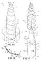
- FIG. 1is a partially broken top perspective view of an embodiment of a helical antenna in accordance with the present invention
- FIG. 2is a top perspective view of the cylindrical and conical sections of the helix support of the embodiment of FIG. 1 in the assembled configuration;
- FIG. 3is a top plan view of the blank of the upper conical section of the helix support of the embodiment of FIG. 1 in its flat development configuration;
- FIG. 4is a top plan view of the blank of the lower cylindrical section of the helix support of the embodiment of FIG. 1 in its flat development configuration;
- FIG. 5is a partially broken enlarged view taken along line 5 of FIG. 2 , showing a locking tab interlocked with the corresponding tab receiving slot for securing the lower sheet into its cylindrical configuration;
- FIG. 6is a partially broken enlarged section view taken along line 6 — 6 of FIG. 5 , showing a ground tab attachment for electrically grounding the two surfaces of the cylindrical section of the helix support to one another;
- FIG. 7is a partially broken enlarged section view taken along line 7 — 7 of FIG. 2 , showing a connecting tab of the conical section resiliently connected in abutting contact engagement against with the corresponding surface of the cylindrical section;
- FIG. 8is a partially broken enlarged view of the conical section of the embodiment of FIG. 1 , showing an attachment of the helical conductor to the helix support;
- FIG. 9is a partially broken enlarged section view taken along line 9 — 9 of FIG. 1 , showing the connection between the cylindrical section and the mounting base;
- FIG. 10is a view similar to FIG. 1 , showing another embodiment of a helical antenna in accordance with the present invention
- FIG. 11is an exploded top perspective view of the helix with the cylindrical and conical sections of the helix support of the embodiment of FIG. 10 during assembly;
- FIG. 12is a partially broken enlarged section view taken along line 12 — 12 of FIG. 11 , showing the bonding and grounding connections of the two surfaces of the cylindrical section of the embodiment of FIG. 10 ;
- FIG. 13is a top plan view of the blank of the upper conical section of the helix support of the embodiment of FIG. 10 in its flat development configuration;
- FIG. 14is a top plan view of the blank of the lower cylindrical section of the helix support of the embodiment of FIG. 10 in its flat development configuration.
- the antenna 10typically includes an electrical conductor or component 12 having a substantially helix shape and defining a helix axis 13 , a helix support 14 and a mounting base 16 generally supporting the support 14 and the helix 12 , and typically having a conventional cup shape 18 .
- an electrical conductor or component 12having a substantially helix shape and defining a helix axis 13
- a helix support 14 and a mounting base 16generally supporting the support 14 and the helix 12
- typically having a conventional cup shape 18typically having a conventional cup shape 18 .
- the present embodiment 10is illustrated with one helical conductor 12 , a plurality of conductors 12 could be used and mounted on the same support 14 without departing from the scope of the present invention.
- the helix support 14is mounted on the mounting base 16 of the antenna 10 .
- the helix support 14includes a first or lower flexible sheet 20 or blank that is curlable, from a first substantially rectangular planar or flat development configuration (see FIG. 4 ) into a second substantially cylindrical configuration, to form a cylindrical-shaped support first section 20 ′ for at least partially supporting a first or lower portion of the helix component 12 there around.
- the first section 20 ′defines a first section axis 22 .
- a second or upper flexible sheet 24 or blankis curlable, from a first substantially truncated triangular planar or flat development configuration (see FIG.
- the second section 24 ′defines a second section axis 26 and is connectable to the first section 20 ′ with the second section axis 26 extending substantially along the first section axis 22 , in a substantially co-linear relationship there between.
- the first and second sections 20 ′, 24 ′support the helix 12 with their axes 13 , 22 , 26 substantially co-linear with each other.
- the first and second sheets 20 , 24are typically made out of a flexible and partially Radio-Frequency (RF) transparent thermoplastic material, such as, but not limited to, commonly known polyester or polyethylene terephthalate (PET) (including MylarTM), polyimide (including KaptonTM), fluorinated ethylene propylene (FEP) (including polytetrafluoroethylene (PTFE) TeflonTM) and the like materials.
- RFRadio-Frequency
- the first flexible sheet 20defines generally opposed first or external and second or internal sheet surfaces 28 , 30 thereof, respectively.
- the first flexible sheet 20generally includes a typically thin layer (in the range of approximately two thousand angstroms (2000 ⁇ ), 0.2 ⁇ m or less, depending on the coating itself) of an antistatic or semi-conductive coating 32 such as, but not limited to, commonly known indium-tin oxide (ITO), germanium, and the like material typically deposited at least on the first sheet surface 28 of the sheet material typically under vacuum condition, although other application processes could be selected such as antistatic paint, spray, dipping and the like.
- ITOindium-tin oxide
- a typical antistatic coating 32provides a surface resistivity typically varying between about ten to the power six to about ten to the power nine ohms per square (10 6 to 10 9 ⁇ / ⁇ ), considering the RF signal frequency transmitted by the antenna 10 .
- both first and second sheet surfaces 28 , 30are coated with the antistatic coating 32 .
- the second flexible sheet 24defines generally opposed third or external and fourth or internal sheet surfaces 34 , 36 thereof, respectively.
- the second flexible sheet 24also generally includes an antistatic coating 32 the third and fourth sheet surfaces including an antistatic coating deposited on the third and fourth sheet surfaces 34 , 36 of the corresponding sheet material.
- the first flexible sheet 20further defines generally opposed first and second interlocking edges 38 , 40 that are interlockable to one another in the cylindrical configuration.
- a grounding meanstypically provides for an electrical grounding between the first and second sheet surfaces 28 , 30 .
- the first and second sheet surfaces 28 , 30are at least partially in an overlap relationship relative to one another at a position adjacent the first and second interlocking edges 38 , 40 respectively, for electrically grounding the two sheet surfaces 28 , 30 to one another when the first flexible sheet 20 is in its cylindrical configuration.
- the first flexible sheet 20includes, at least one, first ground tabs 42 extending substantially outwardly from the first interlocking edge 38 such that the portion of the external sheet surface 28 on the ground tabs 42 is in overlap contact engagement with the internal sheet surface 30 when the first flexible sheet 20 is in its cylindrical configuration, as illustrated in FIGS. 2 , 5 and 6 .
- the second flexible sheet 24further defines generally opposed third and fourth interlocking edges 44 , 46 that are interlockable to one another in the conical configuration.
- the third and fourth sheet surfaces 34 , 36are at least partially in an overlap relationship relative to one another at a position adjacent the third and fourth interlocking edges 44 , 46 respectively, for electrically grounding the two sheet surfaces 34 , 36 to one another when the second flexible sheet 24 is in its conical configuration.
- the second flexible sheet 24includes, at least one, second ground tabs 48 extending substantially outwardly from the third interlocking edge 44 such that the portion of the external sheet surface 34 on the ground tabs 48 is in overlap contact engagement with the internal sheet surface 36 when the second flexible sheet 24 is in its conical configuration, as illustrated in FIG. 2 .
- each ground tab 42 , 48includes an opening 50 , typically circular, extending there through to allow a typical piece of adhesive tape 52 or the like overlapping the ground tab 42 , 48 to have increased available contact surface area with the corresponding underlying sheet surface 28 , 30 , 34 , 36 underneath, as shown in FIGS. 3 to 6 .
- the second flexible sheet 24defines a first or lower interconnecting edge 54 that extends between the third and fourth interlocking edges 44 , 46 .
- the second flexible sheet 24includes, at least one, third ground tabs 56 extending outwardly from the first interconnecting edge 54 so as to have the third sheet surface 34 of the third ground tabs 56 electrically connecting to the second sheet surface 30 at a position adjacent a second or upper interconnecting edge 58 , being interlockable to the first interconnecting edge 54 , that extends between the first and second interlocking edges 38 , 40 when the second section 24 ′ is connected to the first section 20 ′.
- the first flexible sheet 20defines a third or lower interconnecting edge 60 extending between the first and second interlocking edges 38 , 40 and being generally opposite to the second interconnecting edge 58 .
- the first section 20 ′ of the helix support 14is connectable to the mounting base 16 of the antenna 10 with the third interconnecting edge 60 engaging a substantially circular groove 61 thereof, as shown in FIG. 9 .
- the external sheet surface 28 of the support 14is electrically grounded to the generally electrically conductive mounting base 16 using a grounding means such as at least one substantially elongated ground strap 62 made out of a material similar than the helix support 14 and coated on at least one side or surface thereof with an antistatic coating 32 .
- the ground strap 62has its two longitudinal ends of a coated side in contact by abutting engagement with the helix support 14 and the adjacent mounting base 16 respectively under the pressure of pieces of an adhesive tape 64 or the like.
- a locking meansis used to lock the first and second flexible sheets 20 , 24 in their respective cylindrical and conical configurations, as well as to provide some physical reference guides of the required shape and/or size of their configurations.
- the locking meansallows for interlocking the first and second interlocking edges 38 , 40 to one another and at least partially securing the first flexible sheet 20 in its cylindrical configuration.
- the locking meansincludes, at least one, locking tabs 66 that extend outwardly from one of the first and second interlocking edges 38 , 40 and tab receiving slots 68 that extend through the first flexible sheet 20 between the first and second sheet surfaces 28 , 30 and substantially parallel to and adjacent the other one of the first and second interlocking edges 38 , 40 for at least partially receiving a tip portion 70 (in FIG. 6 and in dotted lines in FIGS. 2 and 5 ) of a corresponding locking tab 66 .
- the locking meansalso allows for interlocking the third and fourth interlocking edges 44 , 46 to one another and at least partially securing the second flexible sheet 24 in its conical configuration.
- the locking meansincludes, at least one, locking tabs 72 that extend outwardly from one of the third and fourth interlocking edges 44 , 46 and tab receiving slots 74 that extend through the second flexible sheet 24 between the third and fourth sheet surfaces 34 , 36 and substantially parallel to and adjacent the other one of the third and fourth interlocking edges 44 , 46 for at least partially receiving a tip portion 76 (shown in dotted lines in FIG. 2 ) of a corresponding locking tab 72 .
- a connecting meansis used to connect the first and second flexible sheets 20 , 24 to one another in their respective cylindrical and conical configurations in a end-to-end relationship relative to one another with the second section axis 26 extending substantially along the first section axis 22 , as well as to provide some physical reference guides their connection.
- the connecting meansincludes, at least one, connecting tabs 78 that extend outwardly from one of the first and second interconnecting edges 54 , 58 for connection with the other one of the first and second interconnecting edges 54 , 58 by resilient abutting engagement there against, using the resiliency or flexibility of the material itself, as shown in FIG. 7 .
- the connecting meansincludes tab receiving slots 80 that extend through the corresponding of the first and flexible sheets 20 , 24 of the other one of the first and second interconnecting edges 54 , 58 and substantially parallel to and adjacent the other one of the first and second interconnecting edges 54 , 58 for at least partially receiving a tip portion 82 (shown in dotted lines in FIG. 2 ) of a corresponding connecting tab 78 .
- the first section 20 ′is positioned intermediate the second section 24 ′ and the mounting base 16 .
- the second flexible sheet 24defines a free upper edge 84 that extends between the third and fourth interlocking edges 44 , 46 and is generally opposite to the first interconnecting edge 54 .
- a small circular hole 86is typically located on the second flexible sheet 24 adjacent the free upper edge 84 to essentially locate the position of the upper tip end 88 of the helical conductor 12 .
- the first flexible sheet 20typically includes a window 90 or through opening located generally adjacent a tangent point 91 of the lower end 92 of the helical conductor 12 therewith to avoid possible multipaction effects in space applications, with the tangent point 91 facing the window 90 .
- the helical conductor 12being obviously an electrical conductor itself, is typically grounded via the RF signal connection at its lower end 92 adjacent the antenna base 16 .
- a bead of adhesive 94preferably non-conductive, or any other suitable glue, bonding or fastening agent, either continuous or in multiple segments, is typically located at the intersection there between in addition to the existing compressive contact, as schematically illustrated in FIG. 8 .
- Similar beads of adhesive 94are typically located at the different locking tabs 66 , 72 and connecting tabs 78 to secure them in place and along the circular groove 61 to secure the helix support 14 therein, as schematically represented in FIGS. 5 and 9 , respectively.
- the adhesive 94is non-conductive, especially when Passive Inter-Modulation (PIM) products are of a concern. Otherwise, a conductive adhesive 94 could be considered which would also improve the electrical grounding between the different surfaces.
- PIMPassive Inter-Modulation
- the compressive contactalso typically ensures an electrical grounding between the first and third external sheet surfaces 28 , 34 and the helix conductor 12 whenever required.
- the innovative helical antenna 10is generally made out of the helix conductor or component 12 and the support component 14 , when taken independently in the assembled configuration, are relatively weak or flexible in a respective direction and relatively rigid or stiff in the other. However, when taken together as a whole and structurally interacting or cooperating with each other, they provide an antenna that is relatively rigid in all directions.
- the helix conductor 12is generally a rigid-type electrically conductive material that is typically obtained from machining, forming (plastically shaped), casting or the like manufacturing process.
- the helix component 12taken alone, is generally relatively flexible or weak in the axial direction A and in a bending direction B generally transverse to the axial direction A (as a conventional coil spring) when one longitudinal end is secured to a mounting base 16 while it is generally relatively stiff or rigid in the radial direction C (against compressive loads).
- the helix support 14or first and second flexible sheets 20 , 24 in their formed configuration 20 ′, 24 ′, taken alone, is generally relatively rigid in both the axial and bending directions A, B (especially when secured to the circular groove 61 ) while it is generally relatively flexible in the radial direction C.
- theyWhen assembled together to form the antenna 10 , they essentially structurally cooperate with each other such that the respective directional stiffness provide an antenna 10 that is generally relatively rigid in all the axial, bending and radial directions A, B, C.
- the different locking tabs 66 , 72 and connecting tabs 78 with their corresponding slots 68 , 74 , 80are typically located in-between adjacent windings or spirals of the helix 12 to ensure that the surface underneath the helix 12 is as uniform as possible with no sheet overlap, in order to minimize RF signal losses and multipaction risks.
- the path or pattern of the helix 12 on the first and second flexible sheets 20 , 24is schematically represented in dotted lines in FIGS. 4 and 3 respectively.
- the different slots 68 , 74 , 80 and other openings 50 , 86 , 88 , as well as the different internal and external corners of the first and second flexible sheets 20 , 24are all rounded to avoid conventionally local tears and/or cracks (not shown) that could eventually damage the antenna 10 .
- the antenna 110typically includes an electrical conductor or component 112 made out of a tubular metallic material plastically pre-shaped to the proper helix dimensions, a helix support 114 and a mounting base 16 .
- the helix component 112is generally supported by the helix support 114 , preferably locally using the adhesive 94 , at least partially along the helix 112 .
- the second embodiment 110mainly differs from the first one 10 by its first flexible sheet 120 that includes different locking means and grounding means, more suitable for larger size antennae.
- the flexible sheet 120defines generally opposed first 202 and second 204 end portions thereof, as shown in FIG. 14 .
- the first and second end portions 202 , 204are adapted to be in an overlap relationship relative to one another when the flexible sheet 120 is in its revolution surface configuration to form the support first section 120 ′, as illustrated in FIG. 12 .
- the first sheet surface 28 of the first end portion 202is in contact engagement with the second sheet surface 30 of the second end portion 204 of the first section 120 ′ to form the grounding means between the two sheet surfaces 28 , 30 coated with an antistatic or semi-conductive coating 32 .
- the second end portion 204typically has a plurality of through holes 206 extending from the first sheet surface 28 to the second sheet surface 30 .
- the locking meanstypically includes an adhesive 94 that substantially fills the plurality of through holes 206 to secure the first and second end portions 202 , 204 to one another to maintain the first sheet 120 in its revolution surface configuration.
- the adhesive 94will have a tendency to partially fill in any gap between the two end portions 202 , 204 by capillarity phenomena, to improve the adhesion there between.
- the adhesive 94could be used to improve the electrical grounding if a conductive adhesive 94 is considered.
- the through holes 206are substantially uniformly distributed relative to each other to cover the second end portion 204 to uniformly secure the first section 120 ′ in its revolution surface configuration.
- the through holes 206form spirals located typically half-way in-between spirals of the conductor 112 , to avoid any possible mechanical interference therewith, as seen in FIG. 10 .
- a different quantity of connecting tabs 78are used to connect the second flexible sheet 124 forming the second section 124 ′ of the antenna support 114 to the first section 120 ′. Also, it is to be noted that the second embodiment 110 does not include any multipaction window 90 at the lower end of the first sheet 120 .
- locking tabs 66 , 72are shown as being generally located on a same interlocking edge 40 , 46 , it would be obvious to one skilled in the art that they could be alternately or differently located on both interlocking edges 38 , 40 or 44 , 46 of one of the first and second flexible sheets 20 , 24 , 124 without departing from the scope of the present invention, as evidenced by the lowermost locking tab 66 and corresponding slot 68 of the first flexible sheet 20 .
- grounding meansincluding conductive beads of material, could be used to ground the different coated surfaces to one another and perform the same function as the different ground tabs 42 , 48 , 56 without departing from the scope of the present invention.
- all grounding paths between different antenna componentsare made redundant for increased reliability of the antenna 10 , 110 .
- helix supports 14 , 114are obviously not restricted for use with a helical conductor 12 , 112 of the rigid-type as shown in FIGS. 1 , 8 , 10 and 11 but could support other types of conductor made out of electrically conductive tapes or foils, etched patterns and the like, depending on the actual size and/or requirements of the antenna 10 , 110 .
- a single piece support or multi-piece support 14 , 114could be considered depending on the physical characteristics of the helical antenna 10 , 110 and more specifically of the helical conductor 12 , 112 without departing from the scope of the present invention.
- the flexible support 14 , 114could have the shape of any revolution surface, including but not limited to cylindrical, trunco- conical and hemispherical surfaces, when in the formed configuration without departing from the scope of the present invention.
Landscapes
- Details Of Aerials (AREA)
- Support Of Aerials (AREA)
Abstract
Description
- U.S. Pat. No. 3,573,840, issued Apr. 6, 1971, to Gouillou et al. for “Small Bulk Helically Wound Antennae and Method for Making Same”;
- U.S. Pat. No. 4,945,363, issued Jul. 31, 1990, to Hoffman for “Conical Spiral Antenna”;
- U.S. Pat. No. 5,134,422, issued Jul. 28, 1992, to Auriol for “Helical Type Antenna and Manufacturing Method Thereof”;
- U.S. Pat. No. 5,255,005, issued Oct. 19, 1993, to Terret et al. for “Dual Layer Resonant Quadrifilar Helix Antenna”;
- U.S. Pat. No. 5,329,287, issued Jul. 12, 1994, to Strickland for “End Loaded Helix Antenna”;
- U.S. Pat. No. 5,479,182, issued Dec. 26, 1995, to Sydor for “Short Conical Antenna”;
- U.S. Pat. No. 5,990,848, issued Nov. 23, 1999, to Arinamaa et al. for “Combined Structure of a Helical Antenna and a Dielectric Plate”;
- U.S. Pat. No. 6,002,377 issued Dec. 14, 1999, to Huynh et al. for “Quadrifilar Helix Antenna”;
- U.S. Pat. No. 6,229,499 issued May 8, 2001, to Licul et al. for “Folded Helix Antenna Design”;
- U.S. Pat. No. 6,339,409 issued Jan. 15, 2002, to Warnagiris for “Wide Bandwidth Multi-Mode Antenna”;
- U.S. Pat. No. 6,384,799 issued May 7, 2002, to Otomo et al. for “Antenna Having a Helical Antenna Element Extending Along a Cylindrical Flexible Substrate”;
- U.S. Pat. No. 6,429,830 issued Aug. 6, 2002, to Noro et al. for “Helical Antenna, Antenna Unit, Composite Antenna”;
- U.S. Pat. No. 6,496,159 issued Dec. 17, 2002, to Noro for “Simple Helical Antenna and Method of Producing the Same”;
- U.S. Pat. No. 6,535,179 issued Mar. 18, 2003, to Petros for “Drooping Helix Antenna”; and
- U.S. patent application Ser. No. US 2003/0020670 A1 published Jan. 30, 2003, to Noro for “Helical Antenna”.
Claims (34)
Priority Applications (1)
| Application Number | Priority Date | Filing Date | Title |
|---|---|---|---|
| US10/868,210US7038636B2 (en) | 2003-06-18 | 2004-06-16 | Helical antenna |
Applications Claiming Priority (2)
| Application Number | Priority Date | Filing Date | Title |
|---|---|---|---|
| US47922803P | 2003-06-18 | 2003-06-18 | |
| US10/868,210US7038636B2 (en) | 2003-06-18 | 2004-06-16 | Helical antenna |
Publications (2)
| Publication Number | Publication Date |
|---|---|
| US20040257298A1 US20040257298A1 (en) | 2004-12-23 |
| US7038636B2true US7038636B2 (en) | 2006-05-02 |
Family
ID=33418479
Family Applications (1)
| Application Number | Title | Priority Date | Filing Date |
|---|---|---|---|
| US10/868,210Expired - LifetimeUS7038636B2 (en) | 2003-06-18 | 2004-06-16 | Helical antenna |
Country Status (4)
| Country | Link |
|---|---|
| US (1) | US7038636B2 (en) |
| EP (1) | EP1489685B1 (en) |
| AT (1) | ATE405970T1 (en) |
| DE (1) | DE602004015889D1 (en) |
Cited By (126)
| Publication number | Priority date | Publication date | Assignee | Title |
|---|---|---|---|---|
| US20050179597A1 (en)* | 2004-02-12 | 2005-08-18 | Jean-Francois Pintos | Method of manufacturing an antenna and/or a network of antennas, antenna and/or network of antennas manufactured according to such a method |
| US7142171B1 (en) | 2005-04-14 | 2006-11-28 | Lockheed Martin Corporation | Helix radiating elements for high power applications |
| US20070046557A1 (en)* | 2005-08-26 | 2007-03-01 | Chen Oscal T | Wideband planar dipole antenna |
| US20080122719A1 (en)* | 2006-08-15 | 2008-05-29 | Joymax Electronics Co., Ltd. | Antenna device |
| US20100073259A1 (en)* | 2008-09-25 | 2010-03-25 | Joymax Electronics Co., Ltd. | Antenna device |
| US20100194664A1 (en)* | 2005-04-26 | 2010-08-05 | Blickle Guenter | Antenna rod having an interior sheathed rod with a winding |
| US8692722B2 (en) | 2011-02-01 | 2014-04-08 | Phoenix Contact Development and Manufacturing, Inc. | Wireless field device or wireless field device adapter with removable antenna module |
| US9674711B2 (en) | 2013-11-06 | 2017-06-06 | At&T Intellectual Property I, L.P. | Surface-wave communications and methods thereof |
| US9685992B2 (en) | 2014-10-03 | 2017-06-20 | At&T Intellectual Property I, L.P. | Circuit panel network and methods thereof |
| US9705610B2 (en) | 2014-10-21 | 2017-07-11 | At&T Intellectual Property I, L.P. | Transmission device with impairment compensation and methods for use therewith |
| US9705561B2 (en) | 2015-04-24 | 2017-07-11 | At&T Intellectual Property I, L.P. | Directional coupling device and methods for use therewith |
| US9729197B2 (en) | 2015-10-01 | 2017-08-08 | At&T Intellectual Property I, L.P. | Method and apparatus for communicating network management traffic over a network |
| US9735833B2 (en) | 2015-07-31 | 2017-08-15 | At&T Intellectual Property I, L.P. | Method and apparatus for communications management in a neighborhood network |
| US9742521B2 (en) | 2014-11-20 | 2017-08-22 | At&T Intellectual Property I, L.P. | Transmission device with mode division multiplexing and methods for use therewith |
| US9742462B2 (en) | 2014-12-04 | 2017-08-22 | At&T Intellectual Property I, L.P. | Transmission medium and communication interfaces and methods for use therewith |
| US9749053B2 (en) | 2015-07-23 | 2017-08-29 | At&T Intellectual Property I, L.P. | Node device, repeater and methods for use therewith |
| US9749013B2 (en) | 2015-03-17 | 2017-08-29 | At&T Intellectual Property I, L.P. | Method and apparatus for reducing attenuation of electromagnetic waves guided by a transmission medium |
| US9748626B2 (en) | 2015-05-14 | 2017-08-29 | At&T Intellectual Property I, L.P. | Plurality of cables having different cross-sectional shapes which are bundled together to form a transmission medium |
| US9768833B2 (en) | 2014-09-15 | 2017-09-19 | At&T Intellectual Property I, L.P. | Method and apparatus for sensing a condition in a transmission medium of electromagnetic waves |
| US9769128B2 (en) | 2015-09-28 | 2017-09-19 | At&T Intellectual Property I, L.P. | Method and apparatus for encryption of communications over a network |
| US9769020B2 (en) | 2014-10-21 | 2017-09-19 | At&T Intellectual Property I, L.P. | Method and apparatus for responding to events affecting communications in a communication network |
| US9780834B2 (en) | 2014-10-21 | 2017-10-03 | At&T Intellectual Property I, L.P. | Method and apparatus for transmitting electromagnetic waves |
| US9787412B2 (en) | 2015-06-25 | 2017-10-10 | At&T Intellectual Property I, L.P. | Methods and apparatus for inducing a fundamental wave mode on a transmission medium |
| US9793955B2 (en) | 2015-04-24 | 2017-10-17 | At&T Intellectual Property I, Lp | Passive electrical coupling device and methods for use therewith |
| US9793954B2 (en) | 2015-04-28 | 2017-10-17 | At&T Intellectual Property I, L.P. | Magnetic coupling device and methods for use therewith |
| US9800327B2 (en) | 2014-11-20 | 2017-10-24 | At&T Intellectual Property I, L.P. | Apparatus for controlling operations of a communication device and methods thereof |
| US9820146B2 (en) | 2015-06-12 | 2017-11-14 | At&T Intellectual Property I, L.P. | Method and apparatus for authentication and identity management of communicating devices |
| US9838078B2 (en) | 2015-07-31 | 2017-12-05 | At&T Intellectual Property I, L.P. | Method and apparatus for exchanging communication signals |
| US9838896B1 (en) | 2016-12-09 | 2017-12-05 | At&T Intellectual Property I, L.P. | Method and apparatus for assessing network coverage |
| US9847566B2 (en) | 2015-07-14 | 2017-12-19 | At&T Intellectual Property I, L.P. | Method and apparatus for adjusting a field of a signal to mitigate interference |
| US9847850B2 (en) | 2014-10-14 | 2017-12-19 | At&T Intellectual Property I, L.P. | Method and apparatus for adjusting a mode of communication in a communication network |
| US9853342B2 (en) | 2015-07-14 | 2017-12-26 | At&T Intellectual Property I, L.P. | Dielectric transmission medium connector and methods for use therewith |
| US9860075B1 (en) | 2016-08-26 | 2018-01-02 | At&T Intellectual Property I, L.P. | Method and communication node for broadband distribution |
| US9866276B2 (en) | 2014-10-10 | 2018-01-09 | At&T Intellectual Property I, L.P. | Method and apparatus for arranging communication sessions in a communication system |
| US9865911B2 (en) | 2015-06-25 | 2018-01-09 | At&T Intellectual Property I, L.P. | Waveguide system for slot radiating first electromagnetic waves that are combined into a non-fundamental wave mode second electromagnetic wave on a transmission medium |
| US9866309B2 (en) | 2015-06-03 | 2018-01-09 | At&T Intellectual Property I, Lp | Host node device and methods for use therewith |
| US9871558B2 (en) | 2014-10-21 | 2018-01-16 | At&T Intellectual Property I, L.P. | Guided-wave transmission device and methods for use therewith |
| US9871283B2 (en) | 2015-07-23 | 2018-01-16 | At&T Intellectual Property I, Lp | Transmission medium having a dielectric core comprised of plural members connected by a ball and socket configuration |
| US9871282B2 (en) | 2015-05-14 | 2018-01-16 | At&T Intellectual Property I, L.P. | At least one transmission medium having a dielectric surface that is covered at least in part by a second dielectric |
| US9876264B2 (en) | 2015-10-02 | 2018-01-23 | At&T Intellectual Property I, Lp | Communication system, guided wave switch and methods for use therewith |
| US9876571B2 (en) | 2015-02-20 | 2018-01-23 | At&T Intellectual Property I, Lp | Guided-wave transmission device with non-fundamental mode propagation and methods for use therewith |
| US9882257B2 (en) | 2015-07-14 | 2018-01-30 | At&T Intellectual Property I, L.P. | Method and apparatus for launching a wave mode that mitigates interference |
| US9887447B2 (en) | 2015-05-14 | 2018-02-06 | At&T Intellectual Property I, L.P. | Transmission medium having multiple cores and methods for use therewith |
| US9893795B1 (en) | 2016-12-07 | 2018-02-13 | At&T Intellectual Property I, Lp | Method and repeater for broadband distribution |
| US9906269B2 (en) | 2014-09-17 | 2018-02-27 | At&T Intellectual Property I, L.P. | Monitoring and mitigating conditions in a communication network |
| US9904535B2 (en) | 2015-09-14 | 2018-02-27 | At&T Intellectual Property I, L.P. | Method and apparatus for distributing software |
| US9911020B1 (en) | 2016-12-08 | 2018-03-06 | At&T Intellectual Property I, L.P. | Method and apparatus for tracking via a radio frequency identification device |
| US9913139B2 (en) | 2015-06-09 | 2018-03-06 | At&T Intellectual Property I, L.P. | Signal fingerprinting for authentication of communicating devices |
| US9912033B2 (en) | 2014-10-21 | 2018-03-06 | At&T Intellectual Property I, Lp | Guided wave coupler, coupling module and methods for use therewith |
| US9912027B2 (en) | 2015-07-23 | 2018-03-06 | At&T Intellectual Property I, L.P. | Method and apparatus for exchanging communication signals |
| US9912382B2 (en) | 2015-06-03 | 2018-03-06 | At&T Intellectual Property I, Lp | Network termination and methods for use therewith |
| US9917341B2 (en) | 2015-05-27 | 2018-03-13 | At&T Intellectual Property I, L.P. | Apparatus and method for launching electromagnetic waves and for modifying radial dimensions of the propagating electromagnetic waves |
| US9929755B2 (en) | 2015-07-14 | 2018-03-27 | At&T Intellectual Property I, L.P. | Method and apparatus for coupling an antenna to a device |
| US9927517B1 (en) | 2016-12-06 | 2018-03-27 | At&T Intellectual Property I, L.P. | Apparatus and methods for sensing rainfall |
| US9948333B2 (en) | 2015-07-23 | 2018-04-17 | At&T Intellectual Property I, L.P. | Method and apparatus for wireless communications to mitigate interference |
| US9954287B2 (en) | 2014-11-20 | 2018-04-24 | At&T Intellectual Property I, L.P. | Apparatus for converting wireless signals and electromagnetic waves and methods thereof |
| US9954286B2 (en) | 2014-10-21 | 2018-04-24 | At&T Intellectual Property I, L.P. | Guided-wave transmission device with non-fundamental mode propagation and methods for use therewith |
| US9967173B2 (en) | 2015-07-31 | 2018-05-08 | At&T Intellectual Property I, L.P. | Method and apparatus for authentication and identity management of communicating devices |
| US9973416B2 (en) | 2014-10-02 | 2018-05-15 | At&T Intellectual Property I, L.P. | Method and apparatus that provides fault tolerance in a communication network |
| US9973940B1 (en) | 2017-02-27 | 2018-05-15 | At&T Intellectual Property I, L.P. | Apparatus and methods for dynamic impedance matching of a guided wave launcher |
| US9997819B2 (en) | 2015-06-09 | 2018-06-12 | At&T Intellectual Property I, L.P. | Transmission medium and method for facilitating propagation of electromagnetic waves via a core |
| US9999038B2 (en) | 2013-05-31 | 2018-06-12 | At&T Intellectual Property I, L.P. | Remote distributed antenna system |
| US9998870B1 (en) | 2016-12-08 | 2018-06-12 | At&T Intellectual Property I, L.P. | Method and apparatus for proximity sensing |
| US10009067B2 (en) | 2014-12-04 | 2018-06-26 | At&T Intellectual Property I, L.P. | Method and apparatus for configuring a communication interface |
| US10020844B2 (en) | 2016-12-06 | 2018-07-10 | T&T Intellectual Property I, L.P. | Method and apparatus for broadcast communication via guided waves |
| US10027397B2 (en) | 2016-12-07 | 2018-07-17 | At&T Intellectual Property I, L.P. | Distributed antenna system and methods for use therewith |
| US10044409B2 (en) | 2015-07-14 | 2018-08-07 | At&T Intellectual Property I, L.P. | Transmission medium and methods for use therewith |
| US10051630B2 (en) | 2013-05-31 | 2018-08-14 | At&T Intellectual Property I, L.P. | Remote distributed antenna system |
| US10069185B2 (en) | 2015-06-25 | 2018-09-04 | At&T Intellectual Property I, L.P. | Methods and apparatus for inducing a non-fundamental wave mode on a transmission medium |
| US10069535B2 (en) | 2016-12-08 | 2018-09-04 | At&T Intellectual Property I, L.P. | Apparatus and methods for launching electromagnetic waves having a certain electric field structure |
| US10090606B2 (en) | 2015-07-15 | 2018-10-02 | At&T Intellectual Property I, L.P. | Antenna system with dielectric array and methods for use therewith |
| US10090594B2 (en) | 2016-11-23 | 2018-10-02 | At&T Intellectual Property I, L.P. | Antenna system having structural configurations for assembly |
| US10103422B2 (en) | 2016-12-08 | 2018-10-16 | At&T Intellectual Property I, L.P. | Method and apparatus for mounting network devices |
| US10135145B2 (en) | 2016-12-06 | 2018-11-20 | At&T Intellectual Property I, L.P. | Apparatus and methods for generating an electromagnetic wave along a transmission medium |
| US10139820B2 (en) | 2016-12-07 | 2018-11-27 | At&T Intellectual Property I, L.P. | Method and apparatus for deploying equipment of a communication system |
| US10148016B2 (en) | 2015-07-14 | 2018-12-04 | At&T Intellectual Property I, L.P. | Apparatus and methods for communicating utilizing an antenna array |
| US10168695B2 (en) | 2016-12-07 | 2019-01-01 | At&T Intellectual Property I, L.P. | Method and apparatus for controlling an unmanned aircraft |
| US10178445B2 (en) | 2016-11-23 | 2019-01-08 | At&T Intellectual Property I, L.P. | Methods, devices, and systems for load balancing between a plurality of waveguides |
| US10205655B2 (en) | 2015-07-14 | 2019-02-12 | At&T Intellectual Property I, L.P. | Apparatus and methods for communicating utilizing an antenna array and multiple communication paths |
| US10224634B2 (en) | 2016-11-03 | 2019-03-05 | At&T Intellectual Property I, L.P. | Methods and apparatus for adjusting an operational characteristic of an antenna |
| US10225025B2 (en) | 2016-11-03 | 2019-03-05 | At&T Intellectual Property I, L.P. | Method and apparatus for detecting a fault in a communication system |
| US10243784B2 (en) | 2014-11-20 | 2019-03-26 | At&T Intellectual Property I, L.P. | System for generating topology information and methods thereof |
| US10243270B2 (en) | 2016-12-07 | 2019-03-26 | At&T Intellectual Property I, L.P. | Beam adaptive multi-feed dielectric antenna system and methods for use therewith |
| US10264586B2 (en) | 2016-12-09 | 2019-04-16 | At&T Mobility Ii Llc | Cloud-based packet controller and methods for use therewith |
| US10291334B2 (en) | 2016-11-03 | 2019-05-14 | At&T Intellectual Property I, L.P. | System for detecting a fault in a communication system |
| US10298293B2 (en) | 2017-03-13 | 2019-05-21 | At&T Intellectual Property I, L.P. | Apparatus of communication utilizing wireless network devices |
| US10305190B2 (en) | 2016-12-01 | 2019-05-28 | At&T Intellectual Property I, L.P. | Reflecting dielectric antenna system and methods for use therewith |
| US10312567B2 (en) | 2016-10-26 | 2019-06-04 | At&T Intellectual Property I, L.P. | Launcher with planar strip antenna and methods for use therewith |
| US10326689B2 (en) | 2016-12-08 | 2019-06-18 | At&T Intellectual Property I, L.P. | Method and system for providing alternative communication paths |
| US10326494B2 (en) | 2016-12-06 | 2019-06-18 | At&T Intellectual Property I, L.P. | Apparatus for measurement de-embedding and methods for use therewith |
| US10340603B2 (en) | 2016-11-23 | 2019-07-02 | At&T Intellectual Property I, L.P. | Antenna system having shielded structural configurations for assembly |
| US10340601B2 (en) | 2016-11-23 | 2019-07-02 | At&T Intellectual Property I, L.P. | Multi-antenna system and methods for use therewith |
| US10340983B2 (en) | 2016-12-09 | 2019-07-02 | At&T Intellectual Property I, L.P. | Method and apparatus for surveying remote sites via guided wave communications |
| US10340573B2 (en) | 2016-10-26 | 2019-07-02 | At&T Intellectual Property I, L.P. | Launcher with cylindrical coupling device and methods for use therewith |
| US10355367B2 (en) | 2015-10-16 | 2019-07-16 | At&T Intellectual Property I, L.P. | Antenna structure for exchanging wireless signals |
| US10361489B2 (en) | 2016-12-01 | 2019-07-23 | At&T Intellectual Property I, L.P. | Dielectric dish antenna system and methods for use therewith |
| US10359749B2 (en) | 2016-12-07 | 2019-07-23 | At&T Intellectual Property I, L.P. | Method and apparatus for utilities management via guided wave communication |
| US10374316B2 (en) | 2016-10-21 | 2019-08-06 | At&T Intellectual Property I, L.P. | System and dielectric antenna with non-uniform dielectric |
| US10382976B2 (en) | 2016-12-06 | 2019-08-13 | At&T Intellectual Property I, L.P. | Method and apparatus for managing wireless communications based on communication paths and network device positions |
| US10389029B2 (en) | 2016-12-07 | 2019-08-20 | At&T Intellectual Property I, L.P. | Multi-feed dielectric antenna system with core selection and methods for use therewith |
| US10389037B2 (en) | 2016-12-08 | 2019-08-20 | At&T Intellectual Property I, L.P. | Apparatus and methods for selecting sections of an antenna array and use therewith |
| US10411356B2 (en) | 2016-12-08 | 2019-09-10 | At&T Intellectual Property I, L.P. | Apparatus and methods for selectively targeting communication devices with an antenna array |
| US10439675B2 (en) | 2016-12-06 | 2019-10-08 | At&T Intellectual Property I, L.P. | Method and apparatus for repeating guided wave communication signals |
| US10446936B2 (en) | 2016-12-07 | 2019-10-15 | At&T Intellectual Property I, L.P. | Multi-feed dielectric antenna system and methods for use therewith |
| CN110474145A (en)* | 2019-07-24 | 2019-11-19 | 西安空间无线电技术研究所 | A kind of novel low PIM umbrella antenna |
| US10498044B2 (en) | 2016-11-03 | 2019-12-03 | At&T Intellectual Property I, L.P. | Apparatus for configuring a surface of an antenna |
| US10530505B2 (en) | 2016-12-08 | 2020-01-07 | At&T Intellectual Property I, L.P. | Apparatus and methods for launching electromagnetic waves along a transmission medium |
| US10535928B2 (en) | 2016-11-23 | 2020-01-14 | At&T Intellectual Property I, L.P. | Antenna system and methods for use therewith |
| US10547348B2 (en) | 2016-12-07 | 2020-01-28 | At&T Intellectual Property I, L.P. | Method and apparatus for switching transmission mediums in a communication system |
| US10601494B2 (en) | 2016-12-08 | 2020-03-24 | At&T Intellectual Property I, L.P. | Dual-band communication device and method for use therewith |
| US10637149B2 (en) | 2016-12-06 | 2020-04-28 | At&T Intellectual Property I, L.P. | Injection molded dielectric antenna and methods for use therewith |
| US10650940B2 (en) | 2015-05-15 | 2020-05-12 | At&T Intellectual Property I, L.P. | Transmission medium having a conductive material and methods for use therewith |
| US10694379B2 (en) | 2016-12-06 | 2020-06-23 | At&T Intellectual Property I, L.P. | Waveguide system with device-based authentication and methods for use therewith |
| US10727599B2 (en) | 2016-12-06 | 2020-07-28 | At&T Intellectual Property I, L.P. | Launcher with slot antenna and methods for use therewith |
| US10755542B2 (en) | 2016-12-06 | 2020-08-25 | At&T Intellectual Property I, L.P. | Method and apparatus for surveillance via guided wave communication |
| US10777873B2 (en) | 2016-12-08 | 2020-09-15 | At&T Intellectual Property I, L.P. | Method and apparatus for mounting network devices |
| US10797781B2 (en) | 2015-06-03 | 2020-10-06 | At&T Intellectual Property I, L.P. | Client node device and methods for use therewith |
| US10811767B2 (en) | 2016-10-21 | 2020-10-20 | At&T Intellectual Property I, L.P. | System and dielectric antenna with convex dielectric radome |
| US10819035B2 (en) | 2016-12-06 | 2020-10-27 | At&T Intellectual Property I, L.P. | Launcher with helical antenna and methods for use therewith |
| US10916969B2 (en) | 2016-12-08 | 2021-02-09 | At&T Intellectual Property I, L.P. | Method and apparatus for providing power using an inductive coupling |
| US10938108B2 (en) | 2016-12-08 | 2021-03-02 | At&T Intellectual Property I, L.P. | Frequency selective multi-feed dielectric antenna system and methods for use therewith |
| US11682841B2 (en) | 2021-09-16 | 2023-06-20 | Eagle Technology, Llc | Communications device with helically wound conductive strip and related antenna devices and methods |
| US11977194B2 (en) | 2018-10-25 | 2024-05-07 | National Research Council Of Canada | Printed film electrostatic concentration for radon detection |
| US12027762B2 (en) | 2022-02-10 | 2024-07-02 | Eagle Technology, Llc | Communications device with helically wound conductive strip with lens and related antenna device and method |
| US12230880B2 (en) | 2022-10-20 | 2025-02-18 | Eagle Technology, Llc | Communications device with rhombus shaped-slot radiating antenna and related antenna device and method |
| US12294147B2 (en) | 2022-10-20 | 2025-05-06 | Eagle Technology, Llc | Communications device with helical slot radiating antenna and related antenna device and method |
Families Citing this family (12)
| Publication number | Priority date | Publication date | Assignee | Title |
|---|---|---|---|---|
| US7286099B1 (en)* | 2005-09-02 | 2007-10-23 | Lockheed Martin Corporation | Rotation-independent helical antenna |
| US7336241B2 (en)* | 2005-09-15 | 2008-02-26 | Qualcomm Incorporated | GPS radome-mounted antenna assembly |
| US8038815B2 (en)* | 2007-07-17 | 2011-10-18 | Qualcomm Incorporated | Fluorescent dye to improve primer coverage accuracy for bonding applications |
| WO2011016045A2 (en)* | 2009-08-06 | 2011-02-10 | Indian Space Research Organisation Of Isro | Printed quasi-tapered tape helical array antenna |
| EP2489097B1 (en) | 2009-10-16 | 2014-06-04 | EMS Technologies Canada, Ltd. | Increased gain in an array antenna through optimal suspension of piece-wise linear conductors |
| JP2012019419A (en)* | 2010-07-08 | 2012-01-26 | Fujikura Ltd | Helical antenna, and method of manufacturing the same |
| DE102013104699A1 (en)* | 2013-05-07 | 2014-11-13 | Endress + Hauser Gmbh + Co. Kg | Device for determining the filling level by means of a helical antenna |
| FR3022403B1 (en)* | 2014-06-11 | 2016-06-24 | Renault Sa | WIRELESS COMMUNICATION SYSTEM AND VEHICLE EQUIPPED WITH SUCH A SYSTEM |
| CN104300205B (en)* | 2014-08-22 | 2017-08-25 | 大连海事大学 | A liquid metal helical antenna |
| CN114497975B (en)* | 2022-04-07 | 2022-08-26 | 西安星通通信科技有限公司 | Antenna with spiral cable lifting support structure and spiral cable lifting support structure |
| CN115832668B (en)* | 2022-11-25 | 2025-08-15 | 哈尔滨工业大学 | Spiral antenna device |
| US12438260B1 (en) | 2024-12-20 | 2025-10-07 | Saltenna Inc. | Surface electromagnetic wave antenna |
Citations (26)
| Publication number | Priority date | Publication date | Assignee | Title |
|---|---|---|---|---|
| US2958081A (en)* | 1959-06-30 | 1960-10-25 | Univ Illinois | Unidirectional broadband antenna comprising modified balanced equiangular spiral |
| US3573840A (en) | 1967-12-15 | 1971-04-06 | Onera (Off Nat Aerospatiale) | Small bulk helically wound antennae and method for making same |
| US3633210A (en)* | 1967-05-26 | 1972-01-04 | Philco Ford Corp | Unbalanced conical spiral antenna |
| US3681772A (en)* | 1970-12-31 | 1972-08-01 | Trw Inc | Modulated arm width spiral antenna |
| US4945363A (en) | 1984-05-25 | 1990-07-31 | Revlon, Inc. | Conical spiral antenna |
| US5134422A (en) | 1987-12-10 | 1992-07-28 | Centre National D'etudes Spatiales | Helical type antenna and manufacturing method thereof |
| US5255005A (en) | 1989-11-10 | 1993-10-19 | L'etat Francais Represente Par Leministre Des Pastes Telecommunications Et De L'espace | Dual layer resonant quadrifilar helix antenna |
| US5329287A (en) | 1992-02-24 | 1994-07-12 | Cal Corporation | End loaded helix antenna |
| US5479182A (en) | 1993-03-01 | 1995-12-26 | Her Majesty The Queen In Right Of Canada, As Represented By The Minister Of Communications | Short conical antenna |
| US5479180A (en)* | 1994-03-23 | 1995-12-26 | The United States Of America As Represented By The Secretary Of The Army | High power ultra broadband antenna |
| US5541617A (en)* | 1991-10-21 | 1996-07-30 | Connolly; Peter J. | Monolithic quadrifilar helix antenna |
| US5838285A (en)* | 1995-12-05 | 1998-11-17 | Motorola, Inc. | Wide beamwidth antenna system and method for making the same |
| US5986616A (en)* | 1997-12-30 | 1999-11-16 | Allgon Ab | Antenna system for circularly polarized radio waves including antenna means and interface network |
| US5990848A (en) | 1996-02-16 | 1999-11-23 | Lk-Products Oy | Combined structure of a helical antenna and a dielectric plate |
| US6002377A (en) | 1998-05-08 | 1999-12-14 | Antcom | Quadrifilar helix antenna |
| US6088000A (en)* | 1999-03-05 | 2000-07-11 | Garmin Corporation | Quadrifilar tapered slot antenna |
| US6181297B1 (en)* | 1994-08-25 | 2001-01-30 | Symmetricom, Inc. | Antenna |
| US6229499B1 (en) | 1999-11-05 | 2001-05-08 | Xm Satellite Radio, Inc. | Folded helix antenna design |
| US6339409B1 (en) | 2001-01-24 | 2002-01-15 | Southwest Research Institute | Wide bandwidth multi-mode antenna |
| US6384799B1 (en) | 1998-01-19 | 2002-05-07 | Tokin Corporation | Antenna having a helical antenna element extending along a cylindrical flexible substrate |
| US6429830B2 (en) | 2000-05-18 | 2002-08-06 | Mitsumi Electric Co., Ltd. | Helical antenna, antenna unit, composite antenna |
| US6433755B1 (en)* | 1998-10-30 | 2002-08-13 | Nec Corporation | Helical antenna |
| US6496159B2 (en) | 2000-08-28 | 2002-12-17 | Mitsumi Electric Co., Ltd. | Simple helical antenna and method of producing the same |
| US20030020670A1 (en) | 2001-07-26 | 2003-01-30 | Mitsumi Electric Co. Ltd. | Helical antenna |
| US6535179B1 (en) | 2001-10-02 | 2003-03-18 | Xm Satellite Radio, Inc. | Drooping helix antenna |
| US6778149B2 (en)* | 2001-12-20 | 2004-08-17 | Mitsumi Electric Co., Ltd. | Composite antenna apparatus |
Family Cites Families (8)
| Publication number | Priority date | Publication date | Assignee | Title |
|---|---|---|---|---|
| US20670A (en)* | 1858-06-22 | Portfolio-pile | ||
| JPH0374906A (en)* | 1989-08-16 | 1991-03-29 | Toyo Commun Equip Co Ltd | Manufacture of four-wire fractional slot winding helical antenna |
| WO1991011038A1 (en)* | 1990-01-08 | 1991-07-25 | Toyo Communication Equipment Co., Ltd. | Four-wire fractional winding helical antenna and manufacturing method thereof |
| JP3317521B2 (en)* | 1992-07-06 | 2002-08-26 | 原田工業株式会社 | Manufacturing method of helical antenna for satellite communication |
| US5432524A (en)* | 1993-03-01 | 1995-07-11 | Her Majesty The Queen In Right Of Canada, As Represented By The Minister Of Communications | Drive arrangement for mechanically-steered antennas |
| US5872549A (en)* | 1996-04-30 | 1999-02-16 | Trw Inc. | Feed network for quadrifilar helix antenna |
| US5909196A (en)* | 1996-12-20 | 1999-06-01 | Ericsson Inc. | Dual frequency band quadrifilar helix antenna systems and methods |
| US6107977A (en)* | 1998-08-19 | 2000-08-22 | Qualcomm Incorporated | Helical antenna assembly and tool for assembling same |
- 2004
- 2004-06-16USUS10/868,210patent/US7038636B2/ennot_activeExpired - Lifetime
- 2004-06-17DEDE602004015889Tpatent/DE602004015889D1/ennot_activeExpired - Lifetime
- 2004-06-17EPEP04291524Apatent/EP1489685B1/ennot_activeExpired - Lifetime
- 2004-06-17ATAT04291524Tpatent/ATE405970T1/ennot_activeIP Right Cessation
Patent Citations (26)
| Publication number | Priority date | Publication date | Assignee | Title |
|---|---|---|---|---|
| US2958081A (en)* | 1959-06-30 | 1960-10-25 | Univ Illinois | Unidirectional broadband antenna comprising modified balanced equiangular spiral |
| US3633210A (en)* | 1967-05-26 | 1972-01-04 | Philco Ford Corp | Unbalanced conical spiral antenna |
| US3573840A (en) | 1967-12-15 | 1971-04-06 | Onera (Off Nat Aerospatiale) | Small bulk helically wound antennae and method for making same |
| US3681772A (en)* | 1970-12-31 | 1972-08-01 | Trw Inc | Modulated arm width spiral antenna |
| US4945363A (en) | 1984-05-25 | 1990-07-31 | Revlon, Inc. | Conical spiral antenna |
| US5134422A (en) | 1987-12-10 | 1992-07-28 | Centre National D'etudes Spatiales | Helical type antenna and manufacturing method thereof |
| US5255005A (en) | 1989-11-10 | 1993-10-19 | L'etat Francais Represente Par Leministre Des Pastes Telecommunications Et De L'espace | Dual layer resonant quadrifilar helix antenna |
| US5541617A (en)* | 1991-10-21 | 1996-07-30 | Connolly; Peter J. | Monolithic quadrifilar helix antenna |
| US5329287A (en) | 1992-02-24 | 1994-07-12 | Cal Corporation | End loaded helix antenna |
| US5479182A (en) | 1993-03-01 | 1995-12-26 | Her Majesty The Queen In Right Of Canada, As Represented By The Minister Of Communications | Short conical antenna |
| US5479180A (en)* | 1994-03-23 | 1995-12-26 | The United States Of America As Represented By The Secretary Of The Army | High power ultra broadband antenna |
| US6181297B1 (en)* | 1994-08-25 | 2001-01-30 | Symmetricom, Inc. | Antenna |
| US5838285A (en)* | 1995-12-05 | 1998-11-17 | Motorola, Inc. | Wide beamwidth antenna system and method for making the same |
| US5990848A (en) | 1996-02-16 | 1999-11-23 | Lk-Products Oy | Combined structure of a helical antenna and a dielectric plate |
| US5986616A (en)* | 1997-12-30 | 1999-11-16 | Allgon Ab | Antenna system for circularly polarized radio waves including antenna means and interface network |
| US6384799B1 (en) | 1998-01-19 | 2002-05-07 | Tokin Corporation | Antenna having a helical antenna element extending along a cylindrical flexible substrate |
| US6002377A (en) | 1998-05-08 | 1999-12-14 | Antcom | Quadrifilar helix antenna |
| US6433755B1 (en)* | 1998-10-30 | 2002-08-13 | Nec Corporation | Helical antenna |
| US6088000A (en)* | 1999-03-05 | 2000-07-11 | Garmin Corporation | Quadrifilar tapered slot antenna |
| US6229499B1 (en) | 1999-11-05 | 2001-05-08 | Xm Satellite Radio, Inc. | Folded helix antenna design |
| US6429830B2 (en) | 2000-05-18 | 2002-08-06 | Mitsumi Electric Co., Ltd. | Helical antenna, antenna unit, composite antenna |
| US6496159B2 (en) | 2000-08-28 | 2002-12-17 | Mitsumi Electric Co., Ltd. | Simple helical antenna and method of producing the same |
| US6339409B1 (en) | 2001-01-24 | 2002-01-15 | Southwest Research Institute | Wide bandwidth multi-mode antenna |
| US20030020670A1 (en) | 2001-07-26 | 2003-01-30 | Mitsumi Electric Co. Ltd. | Helical antenna |
| US6535179B1 (en) | 2001-10-02 | 2003-03-18 | Xm Satellite Radio, Inc. | Drooping helix antenna |
| US6778149B2 (en)* | 2001-12-20 | 2004-08-17 | Mitsumi Electric Co., Ltd. | Composite antenna apparatus |
Cited By (142)
| Publication number | Priority date | Publication date | Assignee | Title |
|---|---|---|---|---|
| US20050179597A1 (en)* | 2004-02-12 | 2005-08-18 | Jean-Francois Pintos | Method of manufacturing an antenna and/or a network of antennas, antenna and/or network of antennas manufactured according to such a method |
| US7418776B2 (en)* | 2004-02-12 | 2008-09-02 | Thomson Licensing | Method of manufacturing an antenna |
| US7142171B1 (en) | 2005-04-14 | 2006-11-28 | Lockheed Martin Corporation | Helix radiating elements for high power applications |
| US20100194664A1 (en)* | 2005-04-26 | 2010-08-05 | Blickle Guenter | Antenna rod having an interior sheathed rod with a winding |
| US20070046557A1 (en)* | 2005-08-26 | 2007-03-01 | Chen Oscal T | Wideband planar dipole antenna |
| US7619565B2 (en) | 2005-08-26 | 2009-11-17 | Aonvision Technology Corp. | Wideband planar dipole antenna |
| US20080122719A1 (en)* | 2006-08-15 | 2008-05-29 | Joymax Electronics Co., Ltd. | Antenna device |
| US20100073259A1 (en)* | 2008-09-25 | 2010-03-25 | Joymax Electronics Co., Ltd. | Antenna device |
| US8692722B2 (en) | 2011-02-01 | 2014-04-08 | Phoenix Contact Development and Manufacturing, Inc. | Wireless field device or wireless field device adapter with removable antenna module |
| US10051630B2 (en) | 2013-05-31 | 2018-08-14 | At&T Intellectual Property I, L.P. | Remote distributed antenna system |
| US9999038B2 (en) | 2013-05-31 | 2018-06-12 | At&T Intellectual Property I, L.P. | Remote distributed antenna system |
| US9674711B2 (en) | 2013-11-06 | 2017-06-06 | At&T Intellectual Property I, L.P. | Surface-wave communications and methods thereof |
| US9768833B2 (en) | 2014-09-15 | 2017-09-19 | At&T Intellectual Property I, L.P. | Method and apparatus for sensing a condition in a transmission medium of electromagnetic waves |
| US10063280B2 (en) | 2014-09-17 | 2018-08-28 | At&T Intellectual Property I, L.P. | Monitoring and mitigating conditions in a communication network |
| US9906269B2 (en) | 2014-09-17 | 2018-02-27 | At&T Intellectual Property I, L.P. | Monitoring and mitigating conditions in a communication network |
| US9973416B2 (en) | 2014-10-02 | 2018-05-15 | At&T Intellectual Property I, L.P. | Method and apparatus that provides fault tolerance in a communication network |
| US9685992B2 (en) | 2014-10-03 | 2017-06-20 | At&T Intellectual Property I, L.P. | Circuit panel network and methods thereof |
| US9866276B2 (en) | 2014-10-10 | 2018-01-09 | At&T Intellectual Property I, L.P. | Method and apparatus for arranging communication sessions in a communication system |
| US9847850B2 (en) | 2014-10-14 | 2017-12-19 | At&T Intellectual Property I, L.P. | Method and apparatus for adjusting a mode of communication in a communication network |
| US9960808B2 (en) | 2014-10-21 | 2018-05-01 | At&T Intellectual Property I, L.P. | Guided-wave transmission device and methods for use therewith |
| US9769020B2 (en) | 2014-10-21 | 2017-09-19 | At&T Intellectual Property I, L.P. | Method and apparatus for responding to events affecting communications in a communication network |
| US9780834B2 (en) | 2014-10-21 | 2017-10-03 | At&T Intellectual Property I, L.P. | Method and apparatus for transmitting electromagnetic waves |
| US9876587B2 (en) | 2014-10-21 | 2018-01-23 | At&T Intellectual Property I, L.P. | Transmission device with impairment compensation and methods for use therewith |
| US9871558B2 (en) | 2014-10-21 | 2018-01-16 | At&T Intellectual Property I, L.P. | Guided-wave transmission device and methods for use therewith |
| US9912033B2 (en) | 2014-10-21 | 2018-03-06 | At&T Intellectual Property I, Lp | Guided wave coupler, coupling module and methods for use therewith |
| US9954286B2 (en) | 2014-10-21 | 2018-04-24 | At&T Intellectual Property I, L.P. | Guided-wave transmission device with non-fundamental mode propagation and methods for use therewith |
| US9705610B2 (en) | 2014-10-21 | 2017-07-11 | At&T Intellectual Property I, L.P. | Transmission device with impairment compensation and methods for use therewith |
| US9749083B2 (en) | 2014-11-20 | 2017-08-29 | At&T Intellectual Property I, L.P. | Transmission device with mode division multiplexing and methods for use therewith |
| US9742521B2 (en) | 2014-11-20 | 2017-08-22 | At&T Intellectual Property I, L.P. | Transmission device with mode division multiplexing and methods for use therewith |
| US10243784B2 (en) | 2014-11-20 | 2019-03-26 | At&T Intellectual Property I, L.P. | System for generating topology information and methods thereof |
| US9800327B2 (en) | 2014-11-20 | 2017-10-24 | At&T Intellectual Property I, L.P. | Apparatus for controlling operations of a communication device and methods thereof |
| US9954287B2 (en) | 2014-11-20 | 2018-04-24 | At&T Intellectual Property I, L.P. | Apparatus for converting wireless signals and electromagnetic waves and methods thereof |
| US9742462B2 (en) | 2014-12-04 | 2017-08-22 | At&T Intellectual Property I, L.P. | Transmission medium and communication interfaces and methods for use therewith |
| US10009067B2 (en) | 2014-12-04 | 2018-06-26 | At&T Intellectual Property I, L.P. | Method and apparatus for configuring a communication interface |
| US9876571B2 (en) | 2015-02-20 | 2018-01-23 | At&T Intellectual Property I, Lp | Guided-wave transmission device with non-fundamental mode propagation and methods for use therewith |
| US9876570B2 (en) | 2015-02-20 | 2018-01-23 | At&T Intellectual Property I, Lp | Guided-wave transmission device with non-fundamental mode propagation and methods for use therewith |
| US9749013B2 (en) | 2015-03-17 | 2017-08-29 | At&T Intellectual Property I, L.P. | Method and apparatus for reducing attenuation of electromagnetic waves guided by a transmission medium |
| US9831912B2 (en) | 2015-04-24 | 2017-11-28 | At&T Intellectual Property I, Lp | Directional coupling device and methods for use therewith |
| US9705561B2 (en) | 2015-04-24 | 2017-07-11 | At&T Intellectual Property I, L.P. | Directional coupling device and methods for use therewith |
| US10224981B2 (en) | 2015-04-24 | 2019-03-05 | At&T Intellectual Property I, Lp | Passive electrical coupling device and methods for use therewith |
| US9793955B2 (en) | 2015-04-24 | 2017-10-17 | At&T Intellectual Property I, Lp | Passive electrical coupling device and methods for use therewith |
| US9793954B2 (en) | 2015-04-28 | 2017-10-17 | At&T Intellectual Property I, L.P. | Magnetic coupling device and methods for use therewith |
| US9748626B2 (en) | 2015-05-14 | 2017-08-29 | At&T Intellectual Property I, L.P. | Plurality of cables having different cross-sectional shapes which are bundled together to form a transmission medium |
| US9871282B2 (en) | 2015-05-14 | 2018-01-16 | At&T Intellectual Property I, L.P. | At least one transmission medium having a dielectric surface that is covered at least in part by a second dielectric |
| US9887447B2 (en) | 2015-05-14 | 2018-02-06 | At&T Intellectual Property I, L.P. | Transmission medium having multiple cores and methods for use therewith |
| US10650940B2 (en) | 2015-05-15 | 2020-05-12 | At&T Intellectual Property I, L.P. | Transmission medium having a conductive material and methods for use therewith |
| US9917341B2 (en) | 2015-05-27 | 2018-03-13 | At&T Intellectual Property I, L.P. | Apparatus and method for launching electromagnetic waves and for modifying radial dimensions of the propagating electromagnetic waves |
| US9866309B2 (en) | 2015-06-03 | 2018-01-09 | At&T Intellectual Property I, Lp | Host node device and methods for use therewith |
| US10797781B2 (en) | 2015-06-03 | 2020-10-06 | At&T Intellectual Property I, L.P. | Client node device and methods for use therewith |
| US10050697B2 (en) | 2015-06-03 | 2018-08-14 | At&T Intellectual Property I, L.P. | Host node device and methods for use therewith |
| US9912381B2 (en) | 2015-06-03 | 2018-03-06 | At&T Intellectual Property I, Lp | Network termination and methods for use therewith |
| US9912382B2 (en) | 2015-06-03 | 2018-03-06 | At&T Intellectual Property I, Lp | Network termination and methods for use therewith |
| US9967002B2 (en) | 2015-06-03 | 2018-05-08 | At&T Intellectual I, Lp | Network termination and methods for use therewith |
| US9935703B2 (en) | 2015-06-03 | 2018-04-03 | At&T Intellectual Property I, L.P. | Host node device and methods for use therewith |
| US10812174B2 (en) | 2015-06-03 | 2020-10-20 | At&T Intellectual Property I, L.P. | Client node device and methods for use therewith |
| US9913139B2 (en) | 2015-06-09 | 2018-03-06 | At&T Intellectual Property I, L.P. | Signal fingerprinting for authentication of communicating devices |
| US9997819B2 (en) | 2015-06-09 | 2018-06-12 | At&T Intellectual Property I, L.P. | Transmission medium and method for facilitating propagation of electromagnetic waves via a core |
| US9820146B2 (en) | 2015-06-12 | 2017-11-14 | At&T Intellectual Property I, L.P. | Method and apparatus for authentication and identity management of communicating devices |
| US9865911B2 (en) | 2015-06-25 | 2018-01-09 | At&T Intellectual Property I, L.P. | Waveguide system for slot radiating first electromagnetic waves that are combined into a non-fundamental wave mode second electromagnetic wave on a transmission medium |
| US10069185B2 (en) | 2015-06-25 | 2018-09-04 | At&T Intellectual Property I, L.P. | Methods and apparatus for inducing a non-fundamental wave mode on a transmission medium |
| US9787412B2 (en) | 2015-06-25 | 2017-10-10 | At&T Intellectual Property I, L.P. | Methods and apparatus for inducing a fundamental wave mode on a transmission medium |
| US9847566B2 (en) | 2015-07-14 | 2017-12-19 | At&T Intellectual Property I, L.P. | Method and apparatus for adjusting a field of a signal to mitigate interference |
| US10148016B2 (en) | 2015-07-14 | 2018-12-04 | At&T Intellectual Property I, L.P. | Apparatus and methods for communicating utilizing an antenna array |
| US10205655B2 (en) | 2015-07-14 | 2019-02-12 | At&T Intellectual Property I, L.P. | Apparatus and methods for communicating utilizing an antenna array and multiple communication paths |
| US9929755B2 (en) | 2015-07-14 | 2018-03-27 | At&T Intellectual Property I, L.P. | Method and apparatus for coupling an antenna to a device |
| US10044409B2 (en) | 2015-07-14 | 2018-08-07 | At&T Intellectual Property I, L.P. | Transmission medium and methods for use therewith |
| US9853342B2 (en) | 2015-07-14 | 2017-12-26 | At&T Intellectual Property I, L.P. | Dielectric transmission medium connector and methods for use therewith |
| US9882257B2 (en) | 2015-07-14 | 2018-01-30 | At&T Intellectual Property I, L.P. | Method and apparatus for launching a wave mode that mitigates interference |
| US10090606B2 (en) | 2015-07-15 | 2018-10-02 | At&T Intellectual Property I, L.P. | Antenna system with dielectric array and methods for use therewith |
| US9912027B2 (en) | 2015-07-23 | 2018-03-06 | At&T Intellectual Property I, L.P. | Method and apparatus for exchanging communication signals |
| US9749053B2 (en) | 2015-07-23 | 2017-08-29 | At&T Intellectual Property I, L.P. | Node device, repeater and methods for use therewith |
| US9871283B2 (en) | 2015-07-23 | 2018-01-16 | At&T Intellectual Property I, Lp | Transmission medium having a dielectric core comprised of plural members connected by a ball and socket configuration |
| US9806818B2 (en) | 2015-07-23 | 2017-10-31 | At&T Intellectual Property I, Lp | Node device, repeater and methods for use therewith |
| US9948333B2 (en) | 2015-07-23 | 2018-04-17 | At&T Intellectual Property I, L.P. | Method and apparatus for wireless communications to mitigate interference |
| US9735833B2 (en) | 2015-07-31 | 2017-08-15 | At&T Intellectual Property I, L.P. | Method and apparatus for communications management in a neighborhood network |
| US9967173B2 (en) | 2015-07-31 | 2018-05-08 | At&T Intellectual Property I, L.P. | Method and apparatus for authentication and identity management of communicating devices |
| US9838078B2 (en) | 2015-07-31 | 2017-12-05 | At&T Intellectual Property I, L.P. | Method and apparatus for exchanging communication signals |
| US9904535B2 (en) | 2015-09-14 | 2018-02-27 | At&T Intellectual Property I, L.P. | Method and apparatus for distributing software |
| US9769128B2 (en) | 2015-09-28 | 2017-09-19 | At&T Intellectual Property I, L.P. | Method and apparatus for encryption of communications over a network |
| US9729197B2 (en) | 2015-10-01 | 2017-08-08 | At&T Intellectual Property I, L.P. | Method and apparatus for communicating network management traffic over a network |
| US9876264B2 (en) | 2015-10-02 | 2018-01-23 | At&T Intellectual Property I, Lp | Communication system, guided wave switch and methods for use therewith |
| US10355367B2 (en) | 2015-10-16 | 2019-07-16 | At&T Intellectual Property I, L.P. | Antenna structure for exchanging wireless signals |
| US9860075B1 (en) | 2016-08-26 | 2018-01-02 | At&T Intellectual Property I, L.P. | Method and communication node for broadband distribution |
| US10374316B2 (en) | 2016-10-21 | 2019-08-06 | At&T Intellectual Property I, L.P. | System and dielectric antenna with non-uniform dielectric |
| US10811767B2 (en) | 2016-10-21 | 2020-10-20 | At&T Intellectual Property I, L.P. | System and dielectric antenna with convex dielectric radome |
| US10312567B2 (en) | 2016-10-26 | 2019-06-04 | At&T Intellectual Property I, L.P. | Launcher with planar strip antenna and methods for use therewith |
| US10340573B2 (en) | 2016-10-26 | 2019-07-02 | At&T Intellectual Property I, L.P. | Launcher with cylindrical coupling device and methods for use therewith |
| US10498044B2 (en) | 2016-11-03 | 2019-12-03 | At&T Intellectual Property I, L.P. | Apparatus for configuring a surface of an antenna |
| US10291334B2 (en) | 2016-11-03 | 2019-05-14 | At&T Intellectual Property I, L.P. | System for detecting a fault in a communication system |
| US10225025B2 (en) | 2016-11-03 | 2019-03-05 | At&T Intellectual Property I, L.P. | Method and apparatus for detecting a fault in a communication system |
| US10224634B2 (en) | 2016-11-03 | 2019-03-05 | At&T Intellectual Property I, L.P. | Methods and apparatus for adjusting an operational characteristic of an antenna |
| US10178445B2 (en) | 2016-11-23 | 2019-01-08 | At&T Intellectual Property I, L.P. | Methods, devices, and systems for load balancing between a plurality of waveguides |
| US10090594B2 (en) | 2016-11-23 | 2018-10-02 | At&T Intellectual Property I, L.P. | Antenna system having structural configurations for assembly |
| US10535928B2 (en) | 2016-11-23 | 2020-01-14 | At&T Intellectual Property I, L.P. | Antenna system and methods for use therewith |
| US10340603B2 (en) | 2016-11-23 | 2019-07-02 | At&T Intellectual Property I, L.P. | Antenna system having shielded structural configurations for assembly |
| US10340601B2 (en) | 2016-11-23 | 2019-07-02 | At&T Intellectual Property I, L.P. | Multi-antenna system and methods for use therewith |
| US10361489B2 (en) | 2016-12-01 | 2019-07-23 | At&T Intellectual Property I, L.P. | Dielectric dish antenna system and methods for use therewith |
| US10305190B2 (en) | 2016-12-01 | 2019-05-28 | At&T Intellectual Property I, L.P. | Reflecting dielectric antenna system and methods for use therewith |
| US10326494B2 (en) | 2016-12-06 | 2019-06-18 | At&T Intellectual Property I, L.P. | Apparatus for measurement de-embedding and methods for use therewith |
| US10135145B2 (en) | 2016-12-06 | 2018-11-20 | At&T Intellectual Property I, L.P. | Apparatus and methods for generating an electromagnetic wave along a transmission medium |
| US10819035B2 (en) | 2016-12-06 | 2020-10-27 | At&T Intellectual Property I, L.P. | Launcher with helical antenna and methods for use therewith |
| US10439675B2 (en) | 2016-12-06 | 2019-10-08 | At&T Intellectual Property I, L.P. | Method and apparatus for repeating guided wave communication signals |
| US10020844B2 (en) | 2016-12-06 | 2018-07-10 | T&T Intellectual Property I, L.P. | Method and apparatus for broadcast communication via guided waves |
| US9927517B1 (en) | 2016-12-06 | 2018-03-27 | At&T Intellectual Property I, L.P. | Apparatus and methods for sensing rainfall |
| US10382976B2 (en) | 2016-12-06 | 2019-08-13 | At&T Intellectual Property I, L.P. | Method and apparatus for managing wireless communications based on communication paths and network device positions |
| US10637149B2 (en) | 2016-12-06 | 2020-04-28 | At&T Intellectual Property I, L.P. | Injection molded dielectric antenna and methods for use therewith |
| US10755542B2 (en) | 2016-12-06 | 2020-08-25 | At&T Intellectual Property I, L.P. | Method and apparatus for surveillance via guided wave communication |
| US10694379B2 (en) | 2016-12-06 | 2020-06-23 | At&T Intellectual Property I, L.P. | Waveguide system with device-based authentication and methods for use therewith |
| US10727599B2 (en) | 2016-12-06 | 2020-07-28 | At&T Intellectual Property I, L.P. | Launcher with slot antenna and methods for use therewith |
| US10027397B2 (en) | 2016-12-07 | 2018-07-17 | At&T Intellectual Property I, L.P. | Distributed antenna system and methods for use therewith |
| US10359749B2 (en) | 2016-12-07 | 2019-07-23 | At&T Intellectual Property I, L.P. | Method and apparatus for utilities management via guided wave communication |
| US10139820B2 (en) | 2016-12-07 | 2018-11-27 | At&T Intellectual Property I, L.P. | Method and apparatus for deploying equipment of a communication system |
| US10168695B2 (en) | 2016-12-07 | 2019-01-01 | At&T Intellectual Property I, L.P. | Method and apparatus for controlling an unmanned aircraft |
| US10389029B2 (en) | 2016-12-07 | 2019-08-20 | At&T Intellectual Property I, L.P. | Multi-feed dielectric antenna system with core selection and methods for use therewith |
| US10547348B2 (en) | 2016-12-07 | 2020-01-28 | At&T Intellectual Property I, L.P. | Method and apparatus for switching transmission mediums in a communication system |
| US9893795B1 (en) | 2016-12-07 | 2018-02-13 | At&T Intellectual Property I, Lp | Method and repeater for broadband distribution |
| US10243270B2 (en) | 2016-12-07 | 2019-03-26 | At&T Intellectual Property I, L.P. | Beam adaptive multi-feed dielectric antenna system and methods for use therewith |
| US10446936B2 (en) | 2016-12-07 | 2019-10-15 | At&T Intellectual Property I, L.P. | Multi-feed dielectric antenna system and methods for use therewith |
| US10069535B2 (en) | 2016-12-08 | 2018-09-04 | At&T Intellectual Property I, L.P. | Apparatus and methods for launching electromagnetic waves having a certain electric field structure |
| US10326689B2 (en) | 2016-12-08 | 2019-06-18 | At&T Intellectual Property I, L.P. | Method and system for providing alternative communication paths |
| US10530505B2 (en) | 2016-12-08 | 2020-01-07 | At&T Intellectual Property I, L.P. | Apparatus and methods for launching electromagnetic waves along a transmission medium |
| US10411356B2 (en) | 2016-12-08 | 2019-09-10 | At&T Intellectual Property I, L.P. | Apparatus and methods for selectively targeting communication devices with an antenna array |
| US10389037B2 (en) | 2016-12-08 | 2019-08-20 | At&T Intellectual Property I, L.P. | Apparatus and methods for selecting sections of an antenna array and use therewith |
| US10601494B2 (en) | 2016-12-08 | 2020-03-24 | At&T Intellectual Property I, L.P. | Dual-band communication device and method for use therewith |
| US10938108B2 (en) | 2016-12-08 | 2021-03-02 | At&T Intellectual Property I, L.P. | Frequency selective multi-feed dielectric antenna system and methods for use therewith |
| US9998870B1 (en) | 2016-12-08 | 2018-06-12 | At&T Intellectual Property I, L.P. | Method and apparatus for proximity sensing |
| US10916969B2 (en) | 2016-12-08 | 2021-02-09 | At&T Intellectual Property I, L.P. | Method and apparatus for providing power using an inductive coupling |
| US10103422B2 (en) | 2016-12-08 | 2018-10-16 | At&T Intellectual Property I, L.P. | Method and apparatus for mounting network devices |
| US9911020B1 (en) | 2016-12-08 | 2018-03-06 | At&T Intellectual Property I, L.P. | Method and apparatus for tracking via a radio frequency identification device |
| US10777873B2 (en) | 2016-12-08 | 2020-09-15 | At&T Intellectual Property I, L.P. | Method and apparatus for mounting network devices |
| US9838896B1 (en) | 2016-12-09 | 2017-12-05 | At&T Intellectual Property I, L.P. | Method and apparatus for assessing network coverage |
| US10340983B2 (en) | 2016-12-09 | 2019-07-02 | At&T Intellectual Property I, L.P. | Method and apparatus for surveying remote sites via guided wave communications |
| US10264586B2 (en) | 2016-12-09 | 2019-04-16 | At&T Mobility Ii Llc | Cloud-based packet controller and methods for use therewith |
| US9973940B1 (en) | 2017-02-27 | 2018-05-15 | At&T Intellectual Property I, L.P. | Apparatus and methods for dynamic impedance matching of a guided wave launcher |
| US10298293B2 (en) | 2017-03-13 | 2019-05-21 | At&T Intellectual Property I, L.P. | Apparatus of communication utilizing wireless network devices |
| US11977194B2 (en) | 2018-10-25 | 2024-05-07 | National Research Council Of Canada | Printed film electrostatic concentration for radon detection |
| CN110474145B (en)* | 2019-07-24 | 2020-11-20 | 西安空间无线电技术研究所 | A Novel Low PIM Umbrella Antenna |
| CN110474145A (en)* | 2019-07-24 | 2019-11-19 | 西安空间无线电技术研究所 | A kind of novel low PIM umbrella antenna |
| US11682841B2 (en) | 2021-09-16 | 2023-06-20 | Eagle Technology, Llc | Communications device with helically wound conductive strip and related antenna devices and methods |
| US12027762B2 (en) | 2022-02-10 | 2024-07-02 | Eagle Technology, Llc | Communications device with helically wound conductive strip with lens and related antenna device and method |
| US12230880B2 (en) | 2022-10-20 | 2025-02-18 | Eagle Technology, Llc | Communications device with rhombus shaped-slot radiating antenna and related antenna device and method |
| US12294147B2 (en) | 2022-10-20 | 2025-05-06 | Eagle Technology, Llc | Communications device with helical slot radiating antenna and related antenna device and method |
Also Published As
| Publication number | Publication date |
|---|---|
| EP1489685B1 (en) | 2008-08-20 |
| DE602004015889D1 (en) | 2008-10-02 |
| US20040257298A1 (en) | 2004-12-23 |
| ATE405970T1 (en) | 2008-09-15 |
| EP1489685A1 (en) | 2004-12-22 |
Similar Documents
| Publication | Publication Date | Title |
|---|---|---|
| US7038636B2 (en) | Helical antenna | |
| CN1860648B (en) | Phased Array Antenna with Discrete Capacitive Coupling and Related Methods | |
| EP0877442B1 (en) | Helical antenna | |
| US7463210B2 (en) | Phased array antenna formed as coupled dipole array segments | |
| US9112282B2 (en) | Deployable satellite reflector with a low passive intermodulation design | |
| EP0865100B1 (en) | A small helical antenna with non-directional radiation pattern | |
| WO1996006468A1 (en) | An antenna | |
| JP2007501569A (en) | Phased array antenna absorber and related method | |
| US20060001574A1 (en) | Wideband Patch Antenna | |
| US20100194643A1 (en) | Wideband patch antenna with helix or three dimensional feed | |
| WO2003003510A1 (en) | Patch dipole array antenna including a feed line organizer body and related methods | |
| US6407721B1 (en) | Super thin, cavity free spiral antenna | |
| US6636179B1 (en) | V-type aperture coupled circular polarization patch antenna using microstrip line | |
| US6121936A (en) | Conformable, integrated antenna structure providing multiple radiating apertures | |
| US12027765B2 (en) | Corrugated ground plane apparatus for an antenna | |
| JP3121820B2 (en) | Microstrip array antenna | |
| US20030058170A1 (en) | Circularly polarized wave antenna suitable for miniaturization | |
| US10923825B2 (en) | Spiral antenna system | |
| AU2023321825B2 (en) | Additively manufactured cluster feed | |
| JP7424672B1 (en) | Cavity for radiating element, radiating element unit and radio wave radiation method | |
| JPH04281604A (en) | Spiral antenna and array antenna using the spiral antenna | |
| JP3528406B2 (en) | Chip antenna | |
| US5467094A (en) | Flat antenna low-noise block down converter capacitively coupled to feed network | |
| CN112350052A (en) | Convolute resonant antenna | |
| AU2002312556A1 (en) | Patchdipole array antenna including a feed line organizer body and related methods |
Legal Events
| Date | Code | Title | Description |
|---|---|---|---|
| AS | Assignment | Owner name:EMS TECHNOLOGIES CANADA, LTD., CANADA Free format text:ASSIGNMENT OF ASSIGNORS INTEREST;ASSIGNORS:LAROUCHE, STEVEN;SENECHAL, GERARD;BUSSIERES, FRANCOIS;AND OTHERS;REEL/FRAME:016291/0886 Effective date:20050525 | |
| STCF | Information on status: patent grant | Free format text:PATENTED CASE | |
| AS | Assignment | Owner name:MACDONALD, DETTWILER AND ASSOCIATES CORPORATION, C Free format text:ASSIGNMENT OF ASSIGNORS INTEREST;ASSIGNOR:EMS TECHNOLOGIES CANADA LTD;REEL/FRAME:019489/0404 Effective date:20070601 | |
| FPAY | Fee payment | Year of fee payment:4 | |
| FPAY | Fee payment | Year of fee payment:8 | |
| AS | Assignment | Owner name:ROYAL BANK OF CANADA, AS THE COLLATERAL AGENT, CANADA Free format text:SECURITY INTEREST;ASSIGNORS:DIGITALGLOBE, INC.;MACDONALD, DETTWILER AND ASSOCIATES LTD.;MACDONALD, DETTWILER AND ASSOCIATES CORPORATION;AND OTHERS;REEL/FRAME:044167/0396 Effective date:20171005 Owner name:ROYAL BANK OF CANADA, AS THE COLLATERAL AGENT, CAN Free format text:SECURITY INTEREST;ASSIGNORS:DIGITALGLOBE, INC.;MACDONALD, DETTWILER AND ASSOCIATES LTD.;MACDONALD, DETTWILER AND ASSOCIATES CORPORATION;AND OTHERS;REEL/FRAME:044167/0396 Effective date:20171005 | |
| MAFP | Maintenance fee payment | Free format text:PAYMENT OF MAINTENANCE FEE, 12TH YEAR, LARGE ENTITY (ORIGINAL EVENT CODE: M1553) Year of fee payment:12 | |
| AS | Assignment | Owner name:ROYAL BANK OF CANADA, AS COLLATERAL AGENT, CANADA Free format text:AMENDED AND RESTATED U.S. PATENT AND TRADEMARK SECURITY AGREEMENT;ASSIGNOR:MACDONALD, DETTWILER AND ASSOCIATES CORPORATION;REEL/FRAME:051287/0330 Effective date:20191211 | |
| AS | Assignment | Owner name:MDA GEOSPATIAL SERVICES INC., COLORADO Free format text:RELEASE BY SECURED PARTY;ASSIGNOR:ROYAL BANK OF CANADA;REEL/FRAME:052351/0001 Effective date:20200408 Owner name:MAXAR TECHNOLOGIES ULC, COLORADO Free format text:RELEASE BY SECURED PARTY;ASSIGNOR:ROYAL BANK OF CANADA;REEL/FRAME:052351/0001 Effective date:20200408 Owner name:MACDONALD, DETTWILER AND ASSOCIATES CORPORATION, COLORADO Free format text:RELEASE BY SECURED PARTY;ASSIGNOR:ROYAL BANK OF CANADA;REEL/FRAME:052351/0001 Effective date:20200408 Owner name:MACDONALD, DETTWILER AND ASSOCIATES INC., COLORADO Free format text:RELEASE BY SECURED PARTY;ASSIGNOR:ROYAL BANK OF CANADA;REEL/FRAME:052351/0001 Effective date:20200408 | |
| AS | Assignment | Owner name:THE BANK OF NOVA SCOTIA, CANADA Free format text:SECURITY INTEREST;ASSIGNORS:MAXAR TECHNOLOGIES ULC;MACDONALD,DETTWILER AND ASSOCIATES CORPORATION;MACDONALD, DETTWILER AND ASSOCIATES INC.;REEL/FRAME:052353/0317 Effective date:20200408 | |
| AS | Assignment | Owner name:COMPUTERSHARE TRUST COMPANY OF CANADA, CANADA Free format text:SECURITY INTEREST;ASSIGNORS:MAXAR TECHNOLOGIES ULC;MACDONALD, DETTWILER AND ASSOCIATES CORPORATION;MACDONALD, DETTWILER AND ASSOCIATES INC.;REEL/FRAME:052486/0564 Effective date:20200408 |