US7038438B2 - Controller for a power converter and a method of controlling a switch thereof - Google Patents
Controller for a power converter and a method of controlling a switch thereofDownload PDFInfo
- Publication number
- US7038438B2 US7038438B2US10/767,937US76793704AUS7038438B2US 7038438 B2US7038438 B2US 7038438B2US 76793704 AUS76793704 AUS 76793704AUS 7038438 B2US7038438 B2US 7038438B2
- Authority
- US
- United States
- Prior art keywords
- duty cycle
- signal
- digital
- power converter
- controller
- Prior art date
- Legal status (The legal status is an assumption and is not a legal conclusion. Google has not performed a legal analysis and makes no representation as to the accuracy of the status listed.)
- Expired - Fee Related
Links
- 238000000034methodMethods0.000titleclaimsabstractdescription40
- 230000001105regulatory effectEffects0.000claimsabstractdescription10
- 230000001276controlling effectEffects0.000claimsabstractdescription8
- 230000004048modificationEffects0.000claimsdescription31
- 238000012986modificationMethods0.000claimsdescription31
- 230000008859changeEffects0.000claimsdescription12
- 230000001143conditioned effectEffects0.000claimsdescription9
- 230000003750conditioning effectEffects0.000claimsdescription8
- 230000001131transforming effectEffects0.000claims1
- 238000012545processingMethods0.000description15
- 230000008569processEffects0.000description13
- 230000008901benefitEffects0.000description11
- 238000006243chemical reactionMethods0.000description11
- 238000010586diagramMethods0.000description10
- 230000000295complement effectEffects0.000description5
- 230000004044responseEffects0.000description5
- 230000001934delayEffects0.000description4
- 238000013461designMethods0.000description4
- 238000004519manufacturing processMethods0.000description4
- 230000007423decreaseEffects0.000description3
- 239000000203mixtureSubstances0.000description3
- 238000006467substitution reactionMethods0.000description3
- 230000007547defectEffects0.000description2
- 230000005669field effectEffects0.000description2
- 230000006872improvementEffects0.000description2
- 230000010354integrationEffects0.000description2
- 239000004065semiconductorSubstances0.000description2
- 230000004075alterationEffects0.000description1
- 230000033228biological regulationEffects0.000description1
- 239000003990capacitorSubstances0.000description1
- 230000002860competitive effectEffects0.000description1
- 238000010276constructionMethods0.000description1
- 229910044991metal oxideInorganic materials0.000description1
- 150000004706metal oxidesChemical class0.000description1
- 238000004806packaging method and processMethods0.000description1
- 230000000135prohibitive effectEffects0.000description1
- 230000009467reductionEffects0.000description1
- 238000005070samplingMethods0.000description1
- 238000012360testing methodMethods0.000description1
- 230000001052transient effectEffects0.000description1
Images


Classifications
- H—ELECTRICITY
- H02—GENERATION; CONVERSION OR DISTRIBUTION OF ELECTRIC POWER
- H02M—APPARATUS FOR CONVERSION BETWEEN AC AND AC, BETWEEN AC AND DC, OR BETWEEN DC AND DC, AND FOR USE WITH MAINS OR SIMILAR POWER SUPPLY SYSTEMS; CONVERSION OF DC OR AC INPUT POWER INTO SURGE OUTPUT POWER; CONTROL OR REGULATION THEREOF
- H02M3/00—Conversion of DC power input into DC power output
- H02M3/02—Conversion of DC power input into DC power output without intermediate conversion into AC
- H02M3/04—Conversion of DC power input into DC power output without intermediate conversion into AC by static converters
- H02M3/10—Conversion of DC power input into DC power output without intermediate conversion into AC by static converters using discharge tubes with control electrode or semiconductor devices with control electrode
- H02M3/145—Conversion of DC power input into DC power output without intermediate conversion into AC by static converters using discharge tubes with control electrode or semiconductor devices with control electrode using devices of a triode or transistor type requiring continuous application of a control signal
- H02M3/155—Conversion of DC power input into DC power output without intermediate conversion into AC by static converters using discharge tubes with control electrode or semiconductor devices with control electrode using devices of a triode or transistor type requiring continuous application of a control signal using semiconductor devices only
- H02M3/156—Conversion of DC power input into DC power output without intermediate conversion into AC by static converters using discharge tubes with control electrode or semiconductor devices with control electrode using devices of a triode or transistor type requiring continuous application of a control signal using semiconductor devices only with automatic control of output voltage or current, e.g. switching regulators
- H02M3/157—Conversion of DC power input into DC power output without intermediate conversion into AC by static converters using discharge tubes with control electrode or semiconductor devices with control electrode using devices of a triode or transistor type requiring continuous application of a control signal using semiconductor devices only with automatic control of output voltage or current, e.g. switching regulators with digital control
Definitions
- the present inventionis directed, in general, to power electronics and, more specifically, to a controller for a power converter, method of controlling a duty cycle of a switch of the power converter, and a power converter employing the same.
- a switch mode power converter(also referred to as a “power converter”) is a power supply or power processing circuit that converts an input voltage waveform into a specified output voltage waveform. Controllers associated with the power converters manage an operation thereof by controlling the conduction periods of switches employed therein. Generally, the controllers are coupled between an input and output of the power converter in a feedback loop configuration (also referred to as a “control loop” or “closed control loop”).
- the controllermeasures an output characteristic (e.g., an output voltage) of the power converter and based thereon modifies a duty cycle of the switches of the power converter.
- the duty cycleis a ratio represented by a conduction period of a switch to a switching period thereof. Thus, if a switch conducts for half of the switching period, the duty cycle for the switch would be 0.5 (or 50 percent).
- the controllershould be configured to dynamically increase or decrease the duty cycle of the switches therein to maintain the output characteristic at a desired value.
- controllers associated with the power convertershave primarily been composed of interconnected analog circuits. Analog circuitry, however, is undesirable for numerous reasons as set forth below.
- analog controllerscan require a multitude of interconnected discrete components to obtain a desired functionality of a single controller, which translates into large inventory costs, and more complicated and expensive manufacturing processes.
- the analog controllersalso tend to take up a fairly extensive footprint of the power converters to accommodate the numerous discrete components therein. With a trend toward smaller power converters that parallels an increased level of integration with the loads powered thereby, employing a larger footprint for the controller necessitated by the numerous discrete components that are not easily reduced in size by circuit integration is disadvantageous.
- analog hardwareis generally fixed and inflexible thereby making modifications thereto very difficult, if not impossible, without a complete redesign of the controller.
- Analog circuitryis also subject to packaging and component defects, especially as the number of components increases, and analog circuitry tends to be sensitive to noise leading to further defects therein.
- analog controllerssuffer from several drawbacks that inhibit the effectiveness thereof. Despite the numerous limitations of analog circuitry, however, the analog controllers have been the controllers of choice for use with a majority of commercially available power converters today.
- controllers employing digital circuitryhave been successfully employed in lieu of analog controllers in power converters servicing lower speed or slower response applications (e.g., response times in a range of two to 100 milliseconds) such as uninterruptible power supplies, motor drives and three-phase rectifiers.
- the controllers employing digital circuitry that control power converters servicing such applicationscan generally execute the necessary commands in an allotted amount of time consistent with the respective application.
- controllers employing digital circuitry for use with power converters powering sensitive loadshave not been viable alternatives to analog controllers due, in part, to a necessity for faster control loops and tighter budgetary constraints.
- a typical commercial AC-to-DC or DC-to-DC power converterdemands response times of approximately 20 microseconds or less with closed control loop bandwidth requirements in a range of five to 100 kilohertz.
- the controllers for the power convertersshould also account for sampling within a switching cycle, which is typically two orders of magnitude faster than the lower speed applications mentioned above.
- the fast response timesare presently attainable by controllers employing analog circuitry.
- Cost effective digital signal processorsare generally not capable of meeting the wide bandwidth requirements in the control loops to meet the fast transient response times and high switching frequencies of the power converters.
- overcoming the aforementioned limitationsmay induce cost prohibitive processor designs, when compared to the cost of analog controllers. For instance, a 60 watt DC-to-DC power converter with analog control circuitry may cost around $35, whereas the cost of a digital signal processor alone for the power converter may cost around $15, which is a substantial cost for the control function by itself.
- a controller incorporating a high performance digital signal processorhas, in the past, been too expensive for use with the power converters when compared to the lower cost analog controller.
- the process of analog to digital conversionmay also use “flash conversions” that employ significant circuitry to perform the necessary tasks in an acceptable time period, or ramp generators and counters that take a significant amount of time to perform the conversion function.
- flash conversionsthat employ significant circuitry to perform the necessary tasks in an acceptable time period
- ramp generators and countersthat take a significant amount of time to perform the conversion function.
- the aforementioned complexitiesall contribute either individually or in combination to the complexity of the controller employing digital circuitry.
- controllers employing digital circuitry in power supplieshas been the subject of many references including U.S. Pat. No. 6,005,377 entitled “Programmable Digital Controller for Switch Mode Power Conversion and Power Supply Employing the Same,” to Chen, et al. (“Chen”), issued Dec. 21, 1999, which is incorporated herein by reference.
- Chendiscloses a programmable controller that operates in a digital domain without reliance on operational software or internal analog circuitry to control a switch of a power converter.
- the controlleris embodied in a field programmable gate array with the ability to handle numerous functions simultaneously and in parallel, as opposed to a digital signal processor which handles instructions serially.
- the controllers of Chencan handle bandwidths greater than or equivalent to analog controllers in the range of five to 100 kilohertz. (Column 2, lines 43–57).
- a controllerfor use with a power train of a power converter including a switch configured to conduct for a duty cycle and provide a regulated output characteristic at an output thereof.
- the controllerincludes a sparse analog-to-digital converter configured to determine a difference between the output characteristic and a desired characteristic and provide an error signal representing the difference in discrete steps. A magnitude of the discrete steps is small when the difference is small and the magnitude of the discrete steps is larger when the difference is larger.
- the controlleralso includes a duty cycle processor configured to provide a digital duty cycle signal to control the duty cycle of the switch as a function of the error signal.
- the present inventionprovides a method of controlling a duty cycle of a switch to provide a regulated output characteristic at an output of a power converter.
- the methodincludes measuring a difference between the output characteristic and a desired characteristic and providing an error signal representing the difference in discrete steps. A magnitude of the discrete steps is small when the difference is small and a magnitude of the discrete steps is larger when the difference is larger.
- the methodalso includes providing a digital duty cycle signal to control the duty cycle of the switch as a function of the error signal.
- the present inventionprovides a power converter including, in one embodiment, a power train having a switch configured to conduct for a duty cycle and provide a regulated output characteristic at an output of the power converter.
- the power converteralso includes a controller having a sparse analog-to-digital converter configured to determine a difference between the output characteristic and a desired characteristic and provide an error signal representing the difference in discrete steps. A magnitude of the discrete steps is small when the difference is small and a magnitude of the discrete steps is larger when the difference is larger.
- the controlleralso includes a duty cycle processor configured to provide a digital duty cycle signal to control the duty cycle of the switch as a function of the error signal.
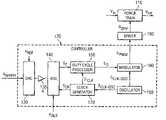
- FIG. 1illustrates a block diagram of an embodiment of a power converter constructed according to the principles of the present invention
- FIG. 2illustrates a schematic diagram of an embodiment of a power train of a power converter constructed according to the principles of the present invention
- FIG. 3illustrates a block diagram of portions of a controller including an embodiment of a sparse analog-to-digital converter constructed according to the principles of the present invention
- FIG. 4illustrates a block diagram of portions of a sparse analog-to-digital converter including an embodiment of a resistor divider coupled to a comparator of a comparator bank constructed according to the principles of the present invention
- FIG. 5illustrates a block diagram of an embodiment of a duty cycle processor constructed according to the principles of the present invention.
- the present inventionwill be described with respect to preferred embodiments in a specific context, namely, a controller for a power converter, method of operation thereof and a power converter employing the same.
- the principles of the present inventionmay also be applied to all types of power supplies employing various conversion topologies that may benefit from a controller employing digital circuitry.
- the advantages associated with the controller and power converterfurther exploit the benefits associated with the application of digital systems in electronic devices.
- the power converterincludes a power train 110 , a controller 120 and a driver 190 , and provides power to a system such as a microprocessor.
- the power train 110may employ a buck converter topology as illustrated and described with respect to FIG. 2 below.
- any number of converter topologiesmay benefit from the use of a controller 120 constructed according to the principles of the present invention and are well within the broad scope of the present invention.
- the power train 110receives an input voltage V in at an input thereof as a power source and provides a regulated output characteristic (e.g., an output voltage) V out to power a microprocessor or other load coupled to an output of the power converter.
- the controller 120receives a digital word representing a desired characteristic such as a desired system voltage V system from an internal or external source associated with the microprocessor, and the output voltage V out of the power converter. In accordance with the aforementioned characteristics, the controller 120 provides a signal to control a duty cycle and a frequency of at least one switch of the power train 110 to regulate the output voltage V out thereof.
- the controller 120includes a digital-to-analog converter (“DAC”) 130 that receives a reference voltage V REF and transforms the desired system voltage V system in the form of a digital word or format into an analog equivalent (i.e., an analog format).
- the reference voltage V REFprovides a reference for a calibration of the digital-to-analog conversion process associated with the DAC 130 .
- the analog format of the desired system voltage V systemis then amplified with a gain K, if necessary, by an operational amplifier 135 .
- a sparse analog-to-digital converter (“ADC”) 140 of the controller 120employs the analog format of the desired system voltage V system and the output voltage V out to provide an error signal S E to a duty cycle processor 150 .
- ADCanalog-to-digital converter
- the error signal S Etypically is in the form of a series of binary error signals (also referred to as “E 1 , . . . E n ”) and represents a difference between the output voltage V out of the power converter and the desired system voltage V system in discrete steps.
- a magnitude of the discrete steps of the error signal S Eis small when the difference is small and a magnitude of the discrete steps of the error signal S E is larger when the difference is larger.
- the sparse ADC 140determines a difference between the output voltage V out and the desired system voltage V system and provides the error signal S E therefrom.
- the duty cycle processor 150then employs the error signal S E to provide a digital duty cycle signal S D (e.g., an eight bit digital signal representing a duty cycle) to control a duty cycle of at least one switch of the power converter.
- a digital duty cycle signal S De.g., an eight bit digital signal representing a duty cycle
- the duty cycle processor 150is coupled to a modulator 180 [e.g., a pulse width modulator (“PWM”)] that converts the digital duty cycle signal S D from the duty cycle processor 150 into a signal so that the driver 190 (e.g., a gate driver) can control at least one switch of the power converter.
- An operation of the duty cycle processor 150is gated by a clock signal S CLK provided by a clock generator 170 .
- the clock generator 170also provides another clock signal S CK for the sparse ADC 140 , which may be shifted in phase as compared to the clock signal S CLK for the duty cycle processor 150 .
- a frequency of the clock signals S CLK , S CKmay be on the order of one thirty-second or one eighth of the switching frequency of the power converter.
- the switching frequency of the modulator 180is typically the same as the switching frequency of the power converter and is controlled by an oscillator (e.g., a ring oscillator) 160 .
- the ring oscillator 160also provides a high frequency clock signal S CLK-OSC to the clock generator 170 , which is divided down to produce the clock signals S CLK , S CK .
- a drive signal(s) S DRVis provided by the driver 190 to control a duty cycle and a frequency of at least one switch of the power converter to regulate the output voltage V out thereof.
- a digital countermay be clocked by the ring oscilator 160 .
- the modulator 180reads the digital duty cycle signal S D from the duty cycle processor 150 and generates a high signal during a portion of the counting cycle that corresponds to a period when a switch of the power converter is being controlled to conduct, and a low signal otherwise. At the end of the counting cycle, the counter resets to zero.
- the ring oscillator 160generates a clock signal S CLK-OSC that can facilitate fine duty cycle granularity or resolution by the modulator 180 thereby allowing accurate control, as necessary, of the output voltage V out of the power converter.
- the moduLator 180supplies a signal that is typically constructed to form a pulse width modulated signal S PWM to control the duty cycle for at least one switch of the power converter.
- the pulse width modulated signal S PWMis then fed to the driver 190 .
- an embodiment of a modulatoris disclosed in U.S. Patent Application Publication No. 2005/0168205, entitled “Controller for a Power Convener and Method of Controlling a Switch Thereof,” to Dwarakanath, et al, which is incorporated herein by reference.
- driver 190there are a number of viable alternatives to implement a driver 190 that include techniques to provide sufficient signal delays to prevent crosscurrents when controlling multiple switches in the power converter.
- any driver 190 capable of providing a drive signal S DRV to control a switchis well within the broad scope of the present invention.
- an embodiment of a driveris disclosed in U.S. Patent Application Publication No. 2005/0168203, entitled “Driver for a Power Convener and Method of Driving a Switch Thereof,” to Dwarakanath, et al., which is incorporated herein by reference.
- FIG. 2illustrated is a schematic diagram of an embodiment of a power train of a power converter constructed according to the principles of the present invention. While in the illustrated embodiment, the power train employs a buck converter topology, those skilled in the art should understand that other converter topologies such as a forward converter topology are well within the broad scope of the present invention.
- the power train of the power converterreceives an input voltage V in from a source of electrical power (represented by a battery) at an input thereof and provides a regulated output voltage V out to power, for instance, a microprocessor at an output of the power converter.
- the output voltage V outis generally less than the input voltage V in such that a switching operation of the power converter can regulate the output voltage V out .
- a main switch Q mne.g., a field effect transistor
- Q mnis enabled to conduct for a primary interval (generally co-existent with a primary duty cycle “D” of the main switch Q mn ) and couples the input voltage V in to an output filter inductor L out .
- an inductor current I Lout flowing through the output filter inductor L outincreases as a current flows from the input to the output of the power train.
- An AC component of the inductor current I Loutis filtered by the output capacitor C out .
- a complementary interval(generally co-existent with a complementary duty cycle “1-D” of the main switch Q mn )
- the main switch Q mnis transitioned to a non-conducting state and an auxiliary switch Q aux (e.g., a freewheeling field effect transistor or freewheeling diode) is enabled to conduct.
- the auxiliary switch Q auxprovides a path to maintain a continuity of the inductor current I Lout flowing through the output filter inductor L out .
- the inductor current I Lout through the output filter inductor L outdecreases.
- the duty cycle of the main and auxiliary switches Q mn , Q auxmay be adjusted to maintain a regulation of the output voltage V out of the power converter.
- the conduction periods for the main and auxiliary switches Q mn , Q auxmay be separated by a small time interval to avoid cross conduction therebetween and beneficially to reduce the switching losses associated with the power converter.
- a controllershould be configured to dynamically increase or decrease the duty cycle of the main and auxiliary switches Q mn , Q aux therein to maintain an output characteristic such as the output voltage V out at a desired value.
- the controller constructed according to the principles of the present inventioncan maintain a well regulated output voltage V out , even in view of an increase in demand on the systems such as microprocessors powered by the power converter.
- FIG. 3illustrated is a block diagram of portions of a controller including an embodiment of a sparse analog-to-digital converter (“ADC”) 310 constructed according to the principles of the present invention.
- ADCanalog-to-digital converter
- a DAC 320 and operational amplifier 330 analogous to the DAC 130 and operational amplifier 135 illustrated and described with respect to FIG. 1are coupled to the sparse ADC 310 . While a reference to the desired system voltage V system in FIG. 1 did not discriminate between the digital, analog and scaled formats thereof, the discussion that follows differentiates between the formats of a desired characteristic (e.g., the desired system voltage V system ) for purposes of clarity.
- V systemdesired characteristic
- the DAC 320operates on a digital format of a desired system voltage V system,d , supplied from an internal or external source, representing a desired characteristic to produce an analog format of the desired system voltage V system,a .
- an analog format of the desired system voltage V system,amay be supplied either from an internal or external source (not shown), without the need for digital to analog conversion.
- the analog format of the desired system voltage V system,amay be scaled by an operational amplifier 330 with a gain K to produce a scaled analog format of the desired system voltage V system,as .
- the scaled representations V s1 , . . . , V s5are coupled to comparators of the comparator bank 350 that produce an error signal (designated as error signal S E in FIG. 1 ) represented by error signals E 1 , . . . , E 5 .
- a timing of the comparators of the comparator bank 350is controlled by a clock signal S CK similar to the another clock signal S CK illustrated and described with respect to FIG. 1 .
- the error signals E 1 , . . . , E 5digitally express an error between two signals, for instance, an output voltage V out of a power converter and a desired system voltage V system .
- E 5typically represent unevenly spaced steps (i.e., discrete steps) in the output voltage V out .
- the selection of resistor values for a resistor divider 340 to provide multiple scaled representations of an input signalare well known to those skilled in the art and in the interest of brevity will not hereinafter be described.
- the resistor divider 340alternatively can be configured to provide an array of scaled representations V s1 , . . . ,V s5 of the output voltage V out with preferably unevenly spaced scaling steps, and the scaled analog format of the desired system voltage V system,as may be coupled to the other inputs of the comparators of the comparator bank 350 .
- the sparse ADC 310avoids conflicting design issues of circuit complexity or computational time delay associated with presently available analog to digital conversion techniques.
- the resulting generation of the cycle-to-cycle changes in duty cyclefurther avoids the corresponding complexity and computational time delay issues associated with further signal processing using microprocessors or digital signal processors.
- the resultis a less complex digital control process for a power converter that can be readily fabricated as a low cost integrated circuit with ordinary integrated circuit processing techniques.
- FIG. 4illustrated is a block diagram of portions of a sparse analog-to-digital converter (“ADC”) including an embodiment of a resistor divider 410 coupled to a comparator 420 of a comparator bank constructed according to the principles of the present invention.
- a DAC 430 and operational amplifier 440analogous to the DAC 130 and operational amplifier 135 illustrated and described with respect to FIG. 1 are coupled to the resistor divider 410 and provide a scaled analog format of a desired system voltage V system,as therefrom.
- the resistor divider 410generally produces scaled representations V s1 , . . . , V sn of a reference voltage on the taps, each representing a scaled desired characteristic.
- the output characteristic of a power converteris coupled to the other inputs of the comparators.
- the taps of the resistor divider 410are typically unevenly spaced so that an accurate estimate of the output characteristic can be made when the output characteristic of the power converter is close to the desired characteristic, and coarser estimates can be made when a greater deviation exists.
- resistor valuescan be selected so that six output characteristic errors of one percent or less, five percent or less, or more than five percent can be recognized, including an indication of the sign of the error.
- the resistor divider 410includes a plurality of resistors R 1 , . . . , R n+1 and an exemplary tap adjacent the second resistor R 2 is coupled to a non-inverting input of the comparator 420 of the comparator bank.
- the comparator 420For the “n” scaled representations V s1 , . . . , V n , “n” comparators are employed in the comparator bank of a sparse ADC.
- the inverting input of the comparator 420is coupled to another signal, for instance, an output voltage V out of a power converter (i.e., an output characteristic of the power converter).
- the comparator 420produces an error signal E 2 indicating whether the output voltage V out is greater or less than a scaled representation V s2 of the scaled analog format of the desired system voltage V system,as .
- E 2the polarity of the inputs to the comparators can be reversed with appropriate compensating inversion of the signal processing in another part of the controller.
- a comparator bankincluding a plurality of comparators generates an error signal(s) as described herein.
- the comparators and sparse ADCdetermine a difference between the output voltage V out of the power converter and a desired characteristic (e.g., a desired system voltage V system ), and provide the error signals therefrom.
- a desired characteristice.g., a desired system voltage V system
- the error signalsare generally embodied as eight bit words or signals, words or signals employing fewer or greater bit lengths are well within the broad scope of the present invention.
- a duty cycle processorincludes a duty cycle encoder that produces a modification signal (i.e., an increment or decrement signal) to change a duty cycle of at least one switch of the power train of the power converter based on a difference between the output voltage V out of the power converter and the desired system voltage V system .
- a modification signali.e., an increment or decrement signal
- the duty cycle encoderproduces a corresponding combination of signals indicating a particular reduction in the duty cycle.
- the modification to the duty cycle produced by the duty cycle encoderdoes not have to be proportional to the error in the output voltage V out of the power converter.
- a sparse ADCemploying five comparators operative with unevenly spaced steps (i.e., discrete steps) for the error signals may provide six possible duty cycle increments and decrements (e.g., scaled as 32, 8, 1, ⁇ 1, ⁇ 8, and ⁇ 32) representing disproportionate modifications to the duty cycle for various errors in the output voltage V out as produced by the five comparators.
- a TABLE provided belowprovides an example for a comparator bank employing five comparators indicating relative increments and decrements of a duty cycle depending on the possible combinations of the errors signals E 1 , . . . , E 5 from the comparators.
- the TABLEincludes the error signals E 1 , . . . , E 5 from the comparators, a modification to the duty cycle (represented by ⁇ D), and a 2's complement representation of a modification to the duty cycle (represented by O 0 , . . . , O 7 ).
- the combination of error signals E 1 , . . . , E 5 from the comparatorsis limited to recognizing a monotonic sequence of voltages from the taps of the resistor divider and the configuration of the circuit.
- ⁇ Dequaling 32, 8, 1, ⁇ 1, ⁇ 8, ⁇ 32.
- the 2's complement representation of the modification to the duty cycleprovides a convenient manner of representing numerical values digitally in anticipation of further numerical processing such as in conjunction with a full adder of the duty cycle processor as described below.
- the duty cycle processorincludes a duty cycle encoder 510 , a duty cycle conditioning circuit 520 , a full adder 530 and a duty cycle register 540 .
- the duty cycle encoder 510produces a modification signal S ⁇ D (i.e., an increment or decrement signal) to change a duty cycle of at least one switch of a power train of a power converter based on a difference between two signals such as an output characteristic of the power converter and a desired characteristic.
- the duty cycle encoder 510is preferably a logic circuit that converts combinations of comparator outputs from a sparse ADC as described above into changes in the duty cycle for at least one switch of the power converter.
- the duty cycle conditioning circuit 520examines the modification signal S ⁇ D and the present duty cycle for a switch of the power train of the power converter to test an admissibility thereof. If the prospective change to the duty cycle is admissible in view of the present duty cycle, then the modification to the duty cycle is allowable and the duty cycle conditioning circuit 520 produces a conditioned modification signal S ⁇ Dc . Otherwise, the modification to the duty cycle is adjusted to meet any limitation in duty cycle for the power converter. For example, if the present duty cycle is 0.5 and the prospective change is 0.1, then the modification to the duty cycle is allowable and the duty cycle conditioning circuit 520 produces a conditioned modification signal S ⁇ Dc . Conversely, if the present duty cycle is 0.95 and the prospective change is 0.1, then the modification to the duty cycle is not allowable and an adjustment to the duty cycle is maintained within the limitations allowable therefor.
- the conditioned modification signal S ⁇ Dcis coupled to a digital processing sequence including the full adder 530 and the duty cycle register 540 .
- the full adder 530 operating in conjunction with the duty cycle register 540modifies and stores contents in a register containing a duty cycle computed in the previous clock cycle to produce a digital duty cycle signal S D to control a duty cycle of at least one switch of the power train of the power converter.
- the full adder 530 and duty cycle register 540are operative to accumulate cycle-by-cycle changes to the duty cycle so that a signal can be derived therefrom to control the duty cycle of at least one switch of the power converter.
- the add and store operationsare gated by a clock signal S CLK that may be one-thirtieth of a switching frequency of the power converter.
- the clock signal S CLK that gates the full adder 530 and the duty cycle register 540can be derived from an external source or can be derived from a clock that provides the switching frequency for the power converter. Since the ultimate modification to the duty cycle is limited by, for instance, the values in the TABLE above and the duty cycle register 540 is incremented or decremented at a rate controlled by the clock, the rate of change of the duty cycle is thereby limited.
- a benefit of the resistance to changeis that an automatic ramp limiting duty cycle modification during startup is inherently provided that might otherwise have been provided in other power converter designs by an additional process.
- a controller for, and related method of, controlling a duty cycle for at Jeast one switch of a power convener with readily attainable and quantifiable advantageshas been introduced.
- Those skilled in the artshould understand that the previously described embodiments of the controller, related method, and power converter employing the same are submitted for illustrative purposes only and that other embodiments capable of changing a duty cycle of at least one switch of a power converter employing discrete steps axe well within the broad scope of the present invention.
- a power converter constructed accordingly to the principles of the present inventionmay be embodied in an integrated circuit.
- portions of the power convertersuch as the controller and the power train (or portions thereof) may also be embodied in an integrated circuit and still be within the broad scope of the present invention.
- selected switches or other devices of the power convertermay be embodied in a semiconductor device as disclosed in U.S. Patent Application Publication No. 2005/0167756, entitled “Laterally Diffused Metal Oxide Semiconductor Device and Method of Forming the Same,” to Lofti, et al., which is incorporated herein by reference.
- the controllerincludes a sparse analog-to-digital converter with fewer components that performs rapid analog to digital signal conversion.
- the sparse analog-to-digital converterpreserves the accuracy of the converted signal when a signal is proximate a desired value, and recognizes substantial differences when the signal deviates further.
- a set of digital signals from the sparse analog-to-digital converteris employed to generate a duty cycle for at least one switch of the power converter with less complex signal processing and elements that can perform expedient duty cycle computation.
- exemplary embodiments of the present inventionhave been illustrated with reference to specific electronic components. Those skilled in the art are aware, however, that components may be substituted (not necessarily with components of the same type) to create desired conditions or accomplish desired results. For instance, multiple components may be substituted for a single component and vice-versa.
- the principles of the present inventionmay be applied to a wide variety of power converters. While the controller has been described in the environment of a power converter, those skilled in the art should understand that the controller and related principles of the present invention may be applied in other environments or applications such as a power amplifier, motor controller, and a system to control an actuator in accordance with a stepper motor or other electromechanical device.
Landscapes
- Engineering & Computer Science (AREA)
- Power Engineering (AREA)
- Dc-Dc Converters (AREA)
Abstract
Description
| TABLE | |||||||||||||
| E1 | E2 | E3 | E4 | E5 | ΔD | O7 | O6 | O5 | O4 | O3 | O2 | O1 | O0 |
| 0 | 0 | 0 | 0 | 0 | 32 | 0 | 0 | 1 | 0 | 0 | 0 | 0 | 0 |
| 0 | 0 | 0 | 0 | 1 | 8 | 0 | 0 | 0 | 0 | 1 | 0 | 0 | 0 |
| 0 | 0 | 0 | 1 | 1 | 1 | 0 | 0 | 0 | 0 | 0 | 0 | 0 | 1 |
| 0 | 0 | 1 | 1 | 1 | −1 | 1 | 1 | 1 | 1 | 1 | 1 | 1 | 1 |
| 0 | 1 | 1 | 1 | 1 | −8 | 1 | 1 | 1 | 1 | 1 | 0 | 0 | 0 |
| 1 | 1 | 1 | 1 | 1 | −32 | 1 | 1 | 1 | 0 | 0 | 0 | 0 | 0 |
Claims (20)
Priority Applications (1)
| Application Number | Priority Date | Filing Date | Title |
|---|---|---|---|
| US10/767,937US7038438B2 (en) | 2004-01-29 | 2004-01-29 | Controller for a power converter and a method of controlling a switch thereof |
Applications Claiming Priority (1)
| Application Number | Priority Date | Filing Date | Title |
|---|---|---|---|
| US10/767,937US7038438B2 (en) | 2004-01-29 | 2004-01-29 | Controller for a power converter and a method of controlling a switch thereof |
Publications (2)
| Publication Number | Publication Date |
|---|---|
| US20050169024A1 US20050169024A1 (en) | 2005-08-04 |
| US7038438B2true US7038438B2 (en) | 2006-05-02 |
Family
ID=34807770
Family Applications (1)
| Application Number | Title | Priority Date | Filing Date |
|---|---|---|---|
| US10/767,937Expired - Fee RelatedUS7038438B2 (en) | 2004-01-29 | 2004-01-29 | Controller for a power converter and a method of controlling a switch thereof |
Country Status (1)
| Country | Link |
|---|---|
| US (1) | US7038438B2 (en) |
Cited By (64)
| Publication number | Priority date | Publication date | Assignee | Title |
|---|---|---|---|---|
| US20060038237A1 (en)* | 2004-08-23 | 2006-02-23 | Lotfi Ashraf W | Integrated circuit incorporating higher voltage devices and low voltage devices therein |
| US20060096088A1 (en)* | 2004-11-10 | 2006-05-11 | Lotfi Ashraf W | Method of manufacturing an encapsulated package for a magnetic device |
| US20060096087A1 (en)* | 2004-11-10 | 2006-05-11 | Lotfi Ashraf W | Method of manufacturing a power module |
| US20060172783A1 (en)* | 2004-07-27 | 2006-08-03 | Silicon Laboratories Inc. | Digital DC/DC converter with SYNC control |
| US20060226823A1 (en)* | 2005-04-08 | 2006-10-12 | O'meara Kevin T | Current-sourced power supplies |
| US20070075816A1 (en)* | 2005-10-05 | 2007-04-05 | Lotfi Ashraf W | Power module with a magnetic device having a conductive clip |
| US20070075817A1 (en)* | 2005-10-05 | 2007-04-05 | Lotfi Ashraf W | Magnetic device having a conductive clip |
| US20070075815A1 (en)* | 2005-10-05 | 2007-04-05 | Lotfi Ashraf W | Method of forming a magnetic device having a conductive clip |
| US20070074386A1 (en)* | 2005-10-05 | 2007-04-05 | Lotfi Ashraf W | Method of forming a power module with a magnetic device having a conductive clip |
| US20070085521A1 (en)* | 2005-10-19 | 2007-04-19 | Canon Kabushiki Kaisha | Power supply for switching operation, electronic apparatus including the same, and method of controlling the same |
| US20070108953A1 (en)* | 2005-11-11 | 2007-05-17 | L&L Engineering, Llc | Non-linear controller for switching power supply |
| US20070112443A1 (en)* | 2005-11-11 | 2007-05-17 | L&L Engineering, Llc | Methods and systems for adaptive control |
| US20070210777A1 (en)* | 2006-03-06 | 2007-09-13 | Cervera Pedro A | Controller for a power converter and method of operating the same |
| US20070224752A1 (en)* | 2004-01-29 | 2007-09-27 | Lotfi Ashraf W | Laterally diffused metal oxide semiconductor device and method of forming the same |
| US20080018366A1 (en)* | 2006-07-20 | 2008-01-24 | Enpirion, Inc. | Driver for switch and a method of driving the same |
| US20080094114A1 (en)* | 2006-10-20 | 2008-04-24 | Mirmira Ramarao Dwarakanath | Controller including a sawtooth generator and method of operating the same |
| US20090009137A1 (en)* | 2007-07-05 | 2009-01-08 | Jun Zhang | Apparatus and method to integrate the power management IC with the system IC |
| US20090065363A1 (en)* | 2007-09-10 | 2009-03-12 | Liakopoulos Trifon M | Electroplating Cell and Tool |
| US20090065361A1 (en)* | 2007-09-10 | 2009-03-12 | Liakopoulos Trifon M | Electrolyte and Method of Producing the Same |
| US20090066468A1 (en)* | 2007-09-10 | 2009-03-12 | Lotfi Ashraf W | Power Converter Employing a Micromagnetic Device |
| US20090066467A1 (en)* | 2007-09-10 | 2009-03-12 | Lotfi Ashraf W | Micromagnetic Device and Method of Forming the Same |
| US20090068347A1 (en)* | 2007-09-10 | 2009-03-12 | Lotfi Ashraf W | Method of Forming a Micromagnetic Device |
| US20090066300A1 (en)* | 2007-09-10 | 2009-03-12 | Lotfi Ashraf W | Power Converter Employing a Micromagnetic Device |
| US20090068761A1 (en)* | 2007-09-10 | 2009-03-12 | Lotfi Ashraf W | Method of Forming a Micromagnetic Device |
| US20090068400A1 (en)* | 2007-09-10 | 2009-03-12 | Lotfi Ashraf W | Micromagnetic Device and Method of Forming the Same |
| US20090068762A1 (en)* | 2007-09-10 | 2009-03-12 | Ken Takahashi | Methods of Processing a Substrate and Forming a Micromagnetic Device |
| US20090167267A1 (en)* | 2007-12-27 | 2009-07-02 | Mirmira Ramarao Dwarakanath | Power Converter with Monotonic Turn-On for Pre-Charged Output Capacitor |
| US20090261791A1 (en)* | 2008-04-16 | 2009-10-22 | Lopata Douglas D | Power Converter with Power Switch Operable in Controlled Current Mode |
| US20100044789A1 (en)* | 2004-01-29 | 2010-02-25 | Enpirion, Incorporated | Integrated Circuit with a Laterally Diffused Metal Oxide Semiconductor Device and Method of Forming the Same |
| US20100052049A1 (en)* | 2004-01-29 | 2010-03-04 | Enpirion, Incorporated, A Delaware Corporation | Integrated Circuit with a Laterally Diffused Metal Oxide Semiconductor Device and Method of Forming the Same |
| US20100052051A1 (en)* | 2004-01-29 | 2010-03-04 | Enpirion, Incorporated, A Delaware Corporation | Integrated Circuit with a Laterally Diffused Metal Oxide Semiconductor Device and Method of Forming the Same |
| US20100052050A1 (en)* | 2004-01-29 | 2010-03-04 | Enpirion, Incorporated | Integrated Circuit with a Laterally Diffused Metal Oxide Semiconductor Device and Method of Forming the Same |
| US20100052639A1 (en)* | 2008-08-29 | 2010-03-04 | Nec Electronics Corporation | Power supply controller having analog to digital converter |
| US20100087036A1 (en)* | 2008-10-02 | 2010-04-08 | Lotfi Ashraf W | Module having a stacked passive element and method of forming the same |
| US20100084750A1 (en)* | 2008-10-02 | 2010-04-08 | Lotfi Ashraf W | Module having a stacked passive element and method of forming the same |
| US7710093B2 (en) | 2004-01-29 | 2010-05-04 | Enpirion, Inc. | Driver for a power converter and a method of driving a switch thereof |
| US20100212150A1 (en)* | 2008-10-02 | 2010-08-26 | Lotfi Ashraf W | Module Having a Stacked Magnetic Device and Semiconductor Device and Method of Forming the Same |
| US20100214746A1 (en)* | 2008-10-02 | 2010-08-26 | Lotfi Ashraf W | Module Having a Stacked Magnetic Device and Semiconductor Device and Method of Forming the Same |
| US7855905B2 (en) | 2004-07-27 | 2010-12-21 | Silicon Laboratories Inc. | Digital power supply controller with integrated microcontroller |
| US20110049621A1 (en)* | 2004-01-29 | 2011-03-03 | Enpirion Incorporated, A Delaware Corporation | Integrated Circuit with a Laterally Diffused Metal Oxide Semiconductor Device and Method of Forming the Same |
| US20110095742A1 (en)* | 2008-04-16 | 2011-04-28 | Douglas Dean Lopata | Power Converter with Controller Operable in Selected Modes of Operation |
| US20110101934A1 (en)* | 2008-04-16 | 2011-05-05 | Douglas Dean Lopata | Power Converter with Controller Operable in Selected Modes of Operation |
| US20110101933A1 (en)* | 2008-04-16 | 2011-05-05 | Douglas Dean Lopata | Power Converter with Controller Operable in Selected Modes of Operation |
| US20110193537A1 (en)* | 2005-11-11 | 2011-08-11 | L&L Engineering Llc | Non-linear pwm controller for dc-to-dc converters |
| US20120159214A1 (en)* | 2008-07-04 | 2012-06-21 | Renesas Electronics Corporation | Power controller for supplying power voltage to functional block |
| US8253196B2 (en) | 2004-01-29 | 2012-08-28 | Enpirion, Inc. | Integrated circuit with a laterally diffused metal oxide semiconductor device and method of forming the same |
| US20130200870A1 (en)* | 2012-02-06 | 2013-08-08 | Kishan Pradhan | Low-dropout voltage regulator having fast transient response to sudden load change |
| US20130342179A1 (en)* | 2010-11-09 | 2013-12-26 | Zentrum Mikroelektronik Dresden Ag | Method for generating pwm signals and a pulse width modulation power converter |
| US20140084892A1 (en)* | 2010-11-09 | 2014-03-27 | Zentrum Mikroelektronik Dresden Ag | Pulse width modulation power converter and control method |
| US8686698B2 (en) | 2008-04-16 | 2014-04-01 | Enpirion, Inc. | Power converter with controller operable in selected modes of operation |
| US8698463B2 (en) | 2008-12-29 | 2014-04-15 | Enpirion, Inc. | Power converter with a dynamically configurable controller based on a power conversion mode |
| US8867295B2 (en) | 2010-12-17 | 2014-10-21 | Enpirion, Inc. | Power converter for a memory module |
| US20150015229A1 (en)* | 2013-07-10 | 2015-01-15 | Kabushiki Kaisha Toshiba | Semiconductor integrated circuit |
| US20150022169A1 (en)* | 2013-07-22 | 2015-01-22 | Lsi Corporation | Feedback/feed forward switched capacitor voltage regulation |
| US9246390B2 (en) | 2008-04-16 | 2016-01-26 | Enpirion, Inc. | Power converter with controller operable in selected modes of operation |
| US9299691B2 (en) | 2012-11-30 | 2016-03-29 | Enpirion, Inc. | Semiconductor device including alternating source and drain regions, and respective source and drain metallic strips |
| US9509217B2 (en) | 2015-04-20 | 2016-11-29 | Altera Corporation | Asymmetric power flow controller for a power converter and method of operating the same |
| US9536938B1 (en) | 2013-11-27 | 2017-01-03 | Altera Corporation | Semiconductor device including a resistor metallic layer and method of forming the same |
| US9548714B2 (en) | 2008-12-29 | 2017-01-17 | Altera Corporation | Power converter with a dynamically configurable controller and output filter |
| US9673192B1 (en) | 2013-11-27 | 2017-06-06 | Altera Corporation | Semiconductor device including a resistor metallic layer and method of forming the same |
| US9673135B2 (en) | 2014-01-13 | 2017-06-06 | Altera Corporation | Semiconductor device having mirror-symmetric terminals and methods of forming the same |
| US20170366116A1 (en)* | 2016-06-17 | 2017-12-21 | Semiconductor Components Industries, Llc | Controlling multiple facets of duty cycle response using a single motor integrated circuit pin |
| US10020739B2 (en) | 2014-03-27 | 2018-07-10 | Altera Corporation | Integrated current replicator and method of operating the same |
| US10103627B2 (en) | 2015-02-26 | 2018-10-16 | Altera Corporation | Packaged integrated circuit including a switch-mode regulator and method of forming the same |
Families Citing this family (16)
| Publication number | Priority date | Publication date | Assignee | Title |
|---|---|---|---|---|
| US7229886B2 (en) | 2004-08-23 | 2007-06-12 | Enpirion, Inc. | Method of forming an integrated circuit incorporating higher voltage devices and low voltage devices therein |
| US7190026B2 (en)* | 2004-08-23 | 2007-03-13 | Enpirion, Inc. | Integrated circuit employable with a power converter |
| US7186606B2 (en)* | 2004-08-23 | 2007-03-06 | Enpirion, Inc. | Method of forming an integrated circuit employable with a power converter |
| US7214985B2 (en)* | 2004-08-23 | 2007-05-08 | Enpirion, Inc. | Integrated circuit incorporating higher voltage devices and low voltage devices therein |
| US7232733B2 (en) | 2004-08-23 | 2007-06-19 | Enpirion, Inc. | Method of forming an integrated circuit incorporating higher voltage devices and low voltage devices therein |
| US7015544B2 (en)* | 2004-08-23 | 2006-03-21 | Enpirion, Inc. | Intergrated circuit employable with a power converter |
| US7195981B2 (en) | 2004-08-23 | 2007-03-27 | Enpirion, Inc. | Method of forming an integrated circuit employable with a power converter |
| US7701731B2 (en) | 2007-02-13 | 2010-04-20 | Akros Silicon Inc. | Signal communication across an isolation barrier |
| US7864546B2 (en)* | 2007-02-13 | 2011-01-04 | Akros Silicon Inc. | DC-DC converter with communication across an isolation pathway |
| US7923710B2 (en) | 2007-03-08 | 2011-04-12 | Akros Silicon Inc. | Digital isolator with communication across an isolation barrier |
| US20080181316A1 (en)* | 2007-01-25 | 2008-07-31 | Philip John Crawley | Partitioned Signal and Power Transfer Across an Isolation Barrier |
| US20100054001A1 (en)* | 2008-08-26 | 2010-03-04 | Kenneth Dyer | AC/DC Converter with Power Factor Correction |
| EP2580601B1 (en)* | 2010-06-11 | 2019-12-11 | CommScope Technologies LLC | Switch-state information aggregation |
| US9136829B2 (en)* | 2011-09-13 | 2015-09-15 | Texas Instruments Incorporated | Method and apparatus for implementing a programmable high resolution ramp signal in digitally controlled power converters |
| JP6763315B2 (en)* | 2017-02-02 | 2020-09-30 | Tdk株式会社 | Switching power supply |
| CN119341361B (en)* | 2024-12-19 | 2025-04-29 | 浙江地芯引力科技有限公司 | Voltage conversion circuit |
Citations (9)
| Publication number | Priority date | Publication date | Assignee | Title |
|---|---|---|---|---|
| US5285369A (en) | 1992-09-01 | 1994-02-08 | Power Integrations, Inc. | Switched mode power supply integrated circuit with start-up self-biasing |
| US5469334A (en) | 1991-09-09 | 1995-11-21 | Power Integrations, Inc. | Plastic quad-packaged switched-mode integrated circuit with integrated transformer windings and mouldings for transformer core pieces |
| US5689213A (en) | 1995-08-23 | 1997-11-18 | Micron Technology, Inc. | Post-fabrication programmable integrated circuit ring oscillator |
| US6005377A (en) | 1997-09-17 | 1999-12-21 | Lucent Technologies Inc. | Programmable digital controller for switch mode power conversion and power supply employing the same |
| US6118351A (en) | 1997-06-10 | 2000-09-12 | Lucent Technologies Inc. | Micromagnetic device for power processing applications and method of manufacture therefor |
| US6255714B1 (en) | 1999-06-22 | 2001-07-03 | Agere Systems Guardian Corporation | Integrated circuit having a micromagnetic device including a ferromagnetic core and method of manufacture therefor |
| US6495019B1 (en) | 2000-04-19 | 2002-12-17 | Agere Systems Inc. | Device comprising micromagnetic components for power applications and process for forming device |
| US6541819B2 (en) | 2001-05-24 | 2003-04-01 | Agere Systems Inc. | Semiconductor device having non-power enhanced and power enhanced metal oxide semiconductor devices and a method of manufacture therefor |
| US6791305B2 (en) | 2002-02-28 | 2004-09-14 | Tdk Corporation | Switching power supply control circuit and switching power supply using same |
Family Cites Families (3)
| Publication number | Priority date | Publication date | Assignee | Title |
|---|---|---|---|---|
| US4761725A (en)* | 1986-08-01 | 1988-08-02 | Unisys Corporation | Digitally controlled A.C. to D.C. power conditioner |
| US4982353A (en)* | 1989-09-28 | 1991-01-01 | General Electric Company | Subsampling time-domain digital filter using sparsely clocked output latch |
| US5594324A (en)* | 1995-03-31 | 1997-01-14 | Space Systems/Loral, Inc. | Stabilized power converter having quantized duty cycle |
- 2004
- 2004-01-29USUS10/767,937patent/US7038438B2/ennot_activeExpired - Fee Related
Patent Citations (9)
| Publication number | Priority date | Publication date | Assignee | Title |
|---|---|---|---|---|
| US5469334A (en) | 1991-09-09 | 1995-11-21 | Power Integrations, Inc. | Plastic quad-packaged switched-mode integrated circuit with integrated transformer windings and mouldings for transformer core pieces |
| US5285369A (en) | 1992-09-01 | 1994-02-08 | Power Integrations, Inc. | Switched mode power supply integrated circuit with start-up self-biasing |
| US5689213A (en) | 1995-08-23 | 1997-11-18 | Micron Technology, Inc. | Post-fabrication programmable integrated circuit ring oscillator |
| US6118351A (en) | 1997-06-10 | 2000-09-12 | Lucent Technologies Inc. | Micromagnetic device for power processing applications and method of manufacture therefor |
| US6005377A (en) | 1997-09-17 | 1999-12-21 | Lucent Technologies Inc. | Programmable digital controller for switch mode power conversion and power supply employing the same |
| US6255714B1 (en) | 1999-06-22 | 2001-07-03 | Agere Systems Guardian Corporation | Integrated circuit having a micromagnetic device including a ferromagnetic core and method of manufacture therefor |
| US6495019B1 (en) | 2000-04-19 | 2002-12-17 | Agere Systems Inc. | Device comprising micromagnetic components for power applications and process for forming device |
| US6541819B2 (en) | 2001-05-24 | 2003-04-01 | Agere Systems Inc. | Semiconductor device having non-power enhanced and power enhanced metal oxide semiconductor devices and a method of manufacture therefor |
| US6791305B2 (en) | 2002-02-28 | 2004-09-14 | Tdk Corporation | Switching power supply control circuit and switching power supply using same |
Non-Patent Citations (4)
| Title |
|---|
| Betancourt-Zamora, R.J. et al., "A 1.5 mW, 200 MHz CMOS VCO for Wireless Biotelemetry," First International Workshop on Design of Mixed-Mode Integrated Circuits and Applications, Cancun, Mexico, pp. 72-74, Jul., 1997. |
| Goodman, J. et al., "An Energy/Security Scalable Encryption Processor Using an Embedded Variable Voltage DC/DC Converter," IEEE Journal of Solid-State Circuits, vol. 33, No. 11 (Nov. 1998). |
| Horowitz, P., et al., "The Art of Electronics," Second Edition, 1989, pp. 288-291, Cambridge University Press, Cambridge, MA. |
| Lotfi, A.W., et al., "Issues and Advances in High-Frequency Magnetics for Switching Power Supplies," Proceedings of the IEEE, Jun. 2001, vol. 89, No. 6, pp. 833-845. |
Cited By (143)
| Publication number | Priority date | Publication date | Assignee | Title |
|---|---|---|---|---|
| US20100044789A1 (en)* | 2004-01-29 | 2010-02-25 | Enpirion, Incorporated | Integrated Circuit with a Laterally Diffused Metal Oxide Semiconductor Device and Method of Forming the Same |
| US20100052051A1 (en)* | 2004-01-29 | 2010-03-04 | Enpirion, Incorporated, A Delaware Corporation | Integrated Circuit with a Laterally Diffused Metal Oxide Semiconductor Device and Method of Forming the Same |
| US7759184B2 (en) | 2004-01-29 | 2010-07-20 | Enpirion, Inc. | Laterally diffused metal oxide semiconductor device and method of forming the same |
| US20110049621A1 (en)* | 2004-01-29 | 2011-03-03 | Enpirion Incorporated, A Delaware Corporation | Integrated Circuit with a Laterally Diffused Metal Oxide Semiconductor Device and Method of Forming the Same |
| US7710093B2 (en) | 2004-01-29 | 2010-05-04 | Enpirion, Inc. | Driver for a power converter and a method of driving a switch thereof |
| US20100052050A1 (en)* | 2004-01-29 | 2010-03-04 | Enpirion, Incorporated | Integrated Circuit with a Laterally Diffused Metal Oxide Semiconductor Device and Method of Forming the Same |
| US20100052049A1 (en)* | 2004-01-29 | 2010-03-04 | Enpirion, Incorporated, A Delaware Corporation | Integrated Circuit with a Laterally Diffused Metal Oxide Semiconductor Device and Method of Forming the Same |
| US8212315B2 (en) | 2004-01-29 | 2012-07-03 | Enpirion, Inc. | Integrated circuit with a laterally diffused metal oxide semiconductor device and method of forming the same |
| US8212317B2 (en) | 2004-01-29 | 2012-07-03 | Enpirion, Inc. | Integrated circuit with a laterally diffused metal oxide semiconductor device and method of forming the same |
| US8212316B2 (en) | 2004-01-29 | 2012-07-03 | Enpirion, Inc. | Integrated circuit with a laterally diffused metal oxide semiconductor device and method of forming the same |
| US8253196B2 (en) | 2004-01-29 | 2012-08-28 | Enpirion, Inc. | Integrated circuit with a laterally diffused metal oxide semiconductor device and method of forming the same |
| US8253195B2 (en) | 2004-01-29 | 2012-08-28 | Enpirion, Inc. | Integrated circuit with a laterally diffused metal oxide semiconductor device and method of forming the same |
| US8253197B2 (en) | 2004-01-29 | 2012-08-28 | Enpirion, Inc. | Integrated circuit with a laterally diffused metal oxide semiconductor device and method of forming the same |
| US20070224752A1 (en)* | 2004-01-29 | 2007-09-27 | Lotfi Ashraf W | Laterally diffused metal oxide semiconductor device and method of forming the same |
| US20070284658A1 (en)* | 2004-01-29 | 2007-12-13 | Lotfi Ashraf W | Laterally Diffused Metal Oxide Semiconductor Device and Method of Forming the Same |
| US8633540B2 (en) | 2004-01-29 | 2014-01-21 | Enpirion, Inc. | Integrated circuit with a laterally diffused metal oxide semiconductor device and method of forming the same |
| US9680008B2 (en) | 2004-01-29 | 2017-06-13 | Empirion, Inc. | Laterally diffused metal oxide semiconductor device and method of forming the same |
| US8716790B2 (en) | 2004-01-29 | 2014-05-06 | Enpirion, Inc. | Laterally diffused metal oxide semiconductor device and method of forming the same |
| US8987815B2 (en) | 2004-01-29 | 2015-03-24 | Enpirion, Inc. | Integrated circuit with a laterally diffused metal oxide semiconductor device and method of forming the same |
| US7855905B2 (en) | 2004-07-27 | 2010-12-21 | Silicon Laboratories Inc. | Digital power supply controller with integrated microcontroller |
| US20060172783A1 (en)* | 2004-07-27 | 2006-08-03 | Silicon Laboratories Inc. | Digital DC/DC converter with SYNC control |
| US7335948B2 (en) | 2004-08-23 | 2008-02-26 | Enpirion, Inc. | Integrated circuit incorporating higher voltage devices and low voltage devices therein |
| US20060038237A1 (en)* | 2004-08-23 | 2006-02-23 | Lotfi Ashraf W | Integrated circuit incorporating higher voltage devices and low voltage devices therein |
| US8043544B2 (en) | 2004-11-10 | 2011-10-25 | Enpirion, Inc. | Method of manufacturing an encapsulated package for a magnetic device |
| US7462317B2 (en) | 2004-11-10 | 2008-12-09 | Enpirion, Inc. | Method of manufacturing an encapsulated package for a magnetic device |
| US20090065964A1 (en)* | 2004-11-10 | 2009-03-12 | Lotfi Ashraf W | Method of Manufacturing an Encapsulated Package for a Magnetic Device |
| US20060096087A1 (en)* | 2004-11-10 | 2006-05-11 | Lotfi Ashraf W | Method of manufacturing a power module |
| US20060096088A1 (en)* | 2004-11-10 | 2006-05-11 | Lotfi Ashraf W | Method of manufacturing an encapsulated package for a magnetic device |
| US7426780B2 (en) | 2004-11-10 | 2008-09-23 | Enpirion, Inc. | Method of manufacturing a power module |
| US8528190B2 (en) | 2004-11-10 | 2013-09-10 | Enpirion, Inc. | Method of manufacturing a power module |
| US7598717B2 (en)* | 2005-04-08 | 2009-10-06 | Northrop Grumman Corporation | Current-sourced power supplies |
| US20060226823A1 (en)* | 2005-04-08 | 2006-10-12 | O'meara Kevin T | Current-sourced power supplies |
| US20100176905A1 (en)* | 2005-10-05 | 2010-07-15 | Lotfi Ashraf W | Magnetic Device Having a Conductive Clip |
| US7688172B2 (en) | 2005-10-05 | 2010-03-30 | Enpirion, Inc. | Magnetic device having a conductive clip |
| US10304615B2 (en) | 2005-10-05 | 2019-05-28 | Enpirion, Inc. | Method of forming a power module with a magnetic device having a conductive clip |
| US8384506B2 (en) | 2005-10-05 | 2013-02-26 | Enpirion, Inc. | Magnetic device having a conductive clip |
| US20070074386A1 (en)* | 2005-10-05 | 2007-04-05 | Lotfi Ashraf W | Method of forming a power module with a magnetic device having a conductive clip |
| US8139362B2 (en) | 2005-10-05 | 2012-03-20 | Enpirion, Inc. | Power module with a magnetic device having a conductive clip |
| US20070075815A1 (en)* | 2005-10-05 | 2007-04-05 | Lotfi Ashraf W | Method of forming a magnetic device having a conductive clip |
| US8701272B2 (en) | 2005-10-05 | 2014-04-22 | Enpirion, Inc. | Method of forming a power module with a magnetic device having a conductive clip |
| US20070075817A1 (en)* | 2005-10-05 | 2007-04-05 | Lotfi Ashraf W | Magnetic device having a conductive clip |
| US8631560B2 (en) | 2005-10-05 | 2014-01-21 | Enpirion, Inc. | Method of forming a magnetic device having a conductive clip |
| US20070075816A1 (en)* | 2005-10-05 | 2007-04-05 | Lotfi Ashraf W | Power module with a magnetic device having a conductive clip |
| US20070085521A1 (en)* | 2005-10-19 | 2007-04-19 | Canon Kabushiki Kaisha | Power supply for switching operation, electronic apparatus including the same, and method of controlling the same |
| US7315159B2 (en)* | 2005-10-19 | 2008-01-01 | Canon Kabushiki Kaisha | Power supply for switching operation, electronic apparatus including the same, and method of controlling the same |
| US7545130B2 (en)* | 2005-11-11 | 2009-06-09 | L&L Engineering, Llc | Non-linear controller for switching power supply |
| US20070108953A1 (en)* | 2005-11-11 | 2007-05-17 | L&L Engineering, Llc | Non-linear controller for switching power supply |
| US20070112443A1 (en)* | 2005-11-11 | 2007-05-17 | L&L Engineering, Llc | Methods and systems for adaptive control |
| US8400130B2 (en)* | 2005-11-11 | 2013-03-19 | Maxim Integrated Products, Inc. | Non-linear PWM controller for DC-to-DC converters |
| US8751021B2 (en) | 2005-11-11 | 2014-06-10 | L & L Engineering, LLC | Methods and systems for adaptive control |
| US20110193537A1 (en)* | 2005-11-11 | 2011-08-11 | L&L Engineering Llc | Non-linear pwm controller for dc-to-dc converters |
| US8014879B2 (en)* | 2005-11-11 | 2011-09-06 | L&L Engineering, Llc | Methods and systems for adaptive control |
| US8700184B2 (en) | 2005-11-11 | 2014-04-15 | L&L Engineering, Llc | Methods and systems for adaptive control |
| US8013580B2 (en) | 2006-03-06 | 2011-09-06 | Enpirion, Inc. | Controller for a power converter and method of operating the same |
| US20070210777A1 (en)* | 2006-03-06 | 2007-09-13 | Cervera Pedro A | Controller for a power converter and method of operating the same |
| US8736241B2 (en) | 2006-03-06 | 2014-05-27 | Enpirion, Inc. | Controller for a power converter and method of operating the same |
| US7521907B2 (en) | 2006-03-06 | 2009-04-21 | Enpirion, Inc. | Controller for a power converter and method of operating the same |
| US20090212751A1 (en)* | 2006-03-06 | 2009-08-27 | Pedro Alou Cervera | Controller for a Power Converter and Method of Operating The Same |
| US9748840B2 (en) | 2006-03-06 | 2017-08-29 | Altera Corporation | Controller for a power converter and method of operating the same |
| US7893676B2 (en) | 2006-07-20 | 2011-02-22 | Enpirion, Inc. | Driver for switch and a method of driving the same |
| US20080018366A1 (en)* | 2006-07-20 | 2008-01-24 | Enpirion, Inc. | Driver for switch and a method of driving the same |
| US7948280B2 (en) | 2006-10-20 | 2011-05-24 | Enpirion, Inc. | Controller including a sawtooth generator and method of operating the same |
| US20080094114A1 (en)* | 2006-10-20 | 2008-04-24 | Mirmira Ramarao Dwarakanath | Controller including a sawtooth generator and method of operating the same |
| US20090009137A1 (en)* | 2007-07-05 | 2009-01-08 | Jun Zhang | Apparatus and method to integrate the power management IC with the system IC |
| US20090068761A1 (en)* | 2007-09-10 | 2009-03-12 | Lotfi Ashraf W | Method of Forming a Micromagnetic Device |
| US20090068762A1 (en)* | 2007-09-10 | 2009-03-12 | Ken Takahashi | Methods of Processing a Substrate and Forming a Micromagnetic Device |
| US7955868B2 (en) | 2007-09-10 | 2011-06-07 | Enpirion, Inc. | Method of forming a micromagnetic device |
| US20110181383A1 (en)* | 2007-09-10 | 2011-07-28 | Lotfi Ashraf W | Micromagnetic Device and Method of Forming the Same |
| US20090066467A1 (en)* | 2007-09-10 | 2009-03-12 | Lotfi Ashraf W | Micromagnetic Device and Method of Forming the Same |
| US8002961B2 (en) | 2007-09-10 | 2011-08-23 | Enpirion, Inc. | Electrolyte and method of producing the same |
| US7943510B2 (en) | 2007-09-10 | 2011-05-17 | Enpirion, Inc. | Methods of processing a substrate and forming a micromagnetic device |
| US20090068347A1 (en)* | 2007-09-10 | 2009-03-12 | Lotfi Ashraf W | Method of Forming a Micromagnetic Device |
| US20110217793A1 (en)* | 2007-09-10 | 2011-09-08 | Ken Takahashi | Methods of Processing a Substrate and Forming a Micromagnetic Device |
| US8018315B2 (en)* | 2007-09-10 | 2011-09-13 | Enpirion, Inc. | Power converter employing a micromagnetic device |
| US8618900B2 (en) | 2007-09-10 | 2013-12-31 | Enpirion, Inc. | Micromagnetic device and method of forming the same |
| US8133529B2 (en) | 2007-09-10 | 2012-03-13 | Enpirion, Inc. | Method of forming a micromagnetic device |
| US9611561B2 (en) | 2007-09-10 | 2017-04-04 | Enpirion, Inc. | Electroplating cell and tool |
| US9299489B2 (en) | 2007-09-10 | 2016-03-29 | Enpirion, Inc. | Micromagnetic device and method of forming the same |
| US20090066468A1 (en)* | 2007-09-10 | 2009-03-12 | Lotfi Ashraf W | Power Converter Employing a Micromagnetic Device |
| US20090065361A1 (en)* | 2007-09-10 | 2009-03-12 | Liakopoulos Trifon M | Electrolyte and Method of Producing the Same |
| US20090065363A1 (en)* | 2007-09-10 | 2009-03-12 | Liakopoulos Trifon M | Electroplating Cell and Tool |
| US20090066300A1 (en)* | 2007-09-10 | 2009-03-12 | Lotfi Ashraf W | Power Converter Employing a Micromagnetic Device |
| US20090068400A1 (en)* | 2007-09-10 | 2009-03-12 | Lotfi Ashraf W | Micromagnetic Device and Method of Forming the Same |
| US7544995B2 (en) | 2007-09-10 | 2009-06-09 | Enpirion, Inc. | Power converter employing a micromagnetic device |
| US8339232B2 (en) | 2007-09-10 | 2012-12-25 | Enpirion, Inc. | Micromagnetic device and method of forming the same |
| US7952459B2 (en)* | 2007-09-10 | 2011-05-31 | Enpirion, Inc. | Micromagnetic device and method of forming the same |
| US7920042B2 (en) | 2007-09-10 | 2011-04-05 | Enpirion, Inc. | Micromagnetic device and method of forming the same |
| US8288277B2 (en) | 2007-09-10 | 2012-10-16 | Enpirion, Inc. | Methods of processing a substrate and forming a micromagnetic device |
| US7876080B2 (en) | 2007-12-27 | 2011-01-25 | Enpirion, Inc. | Power converter with monotonic turn-on for pre-charged output capacitor |
| US20090167267A1 (en)* | 2007-12-27 | 2009-07-02 | Mirmira Ramarao Dwarakanath | Power Converter with Monotonic Turn-On for Pre-Charged Output Capacitor |
| US8541991B2 (en) | 2008-04-16 | 2013-09-24 | Enpirion, Inc. | Power converter with controller operable in selected modes of operation |
| US20090261791A1 (en)* | 2008-04-16 | 2009-10-22 | Lopata Douglas D | Power Converter with Power Switch Operable in Controlled Current Mode |
| US20110095742A1 (en)* | 2008-04-16 | 2011-04-28 | Douglas Dean Lopata | Power Converter with Controller Operable in Selected Modes of Operation |
| US8686698B2 (en) | 2008-04-16 | 2014-04-01 | Enpirion, Inc. | Power converter with controller operable in selected modes of operation |
| US8410769B2 (en) | 2008-04-16 | 2013-04-02 | Enpirion, Inc. | Power converter with controller operable in selected modes of operation |
| US8692532B2 (en) | 2008-04-16 | 2014-04-08 | Enpirion, Inc. | Power converter with controller operable in selected modes of operation |
| US20100156374A1 (en)* | 2008-04-16 | 2010-06-24 | Lopata Douglas D | Power Converter with Power Switch Operable in Controlled Current Mode |
| US9246390B2 (en) | 2008-04-16 | 2016-01-26 | Enpirion, Inc. | Power converter with controller operable in selected modes of operation |
| US20110101934A1 (en)* | 2008-04-16 | 2011-05-05 | Douglas Dean Lopata | Power Converter with Controller Operable in Selected Modes of Operation |
| US8283901B2 (en) | 2008-04-16 | 2012-10-09 | Enpirion, Inc. | Power converter with power switch operable in controlled current mode |
| US20100141228A1 (en)* | 2008-04-16 | 2010-06-10 | Lopata Douglas D | Power Converter with Power Switch Operable in Controlled Current Mode |
| US8154261B2 (en) | 2008-04-16 | 2012-04-10 | Enpirion, Inc. | Power converter with power switch operable in controlled current mode |
| US7679342B2 (en) | 2008-04-16 | 2010-03-16 | Enpirion, Inc. | Power converter with power switch operable in controlled current mode |
| US20110101933A1 (en)* | 2008-04-16 | 2011-05-05 | Douglas Dean Lopata | Power Converter with Controller Operable in Selected Modes of Operation |
| US20120159214A1 (en)* | 2008-07-04 | 2012-06-21 | Renesas Electronics Corporation | Power controller for supplying power voltage to functional block |
| US8471544B2 (en)* | 2008-07-04 | 2013-06-25 | Renesas Electronics Corporation | Power controller for supplying power voltage to functional block |
| US20100052639A1 (en)* | 2008-08-29 | 2010-03-04 | Nec Electronics Corporation | Power supply controller having analog to digital converter |
| US8581566B2 (en) | 2008-08-29 | 2013-11-12 | Renesas Electronics Corporation | Power supply controller having analog to digital converter |
| US8310220B2 (en)* | 2008-08-29 | 2012-11-13 | Renesas Electronics Corporation | Power supply controller having analog to digital converter |
| US8564268B2 (en) | 2008-08-29 | 2013-10-22 | Renesas Electronics Corporation | Power supply controller having analog to digital converter |
| US8339802B2 (en) | 2008-10-02 | 2012-12-25 | Enpirion, Inc. | Module having a stacked magnetic device and semiconductor device and method of forming the same |
| US20100214746A1 (en)* | 2008-10-02 | 2010-08-26 | Lotfi Ashraf W | Module Having a Stacked Magnetic Device and Semiconductor Device and Method of Forming the Same |
| US8266793B2 (en) | 2008-10-02 | 2012-09-18 | Enpirion, Inc. | Module having a stacked magnetic device and semiconductor device and method of forming the same |
| US20100087036A1 (en)* | 2008-10-02 | 2010-04-08 | Lotfi Ashraf W | Module having a stacked passive element and method of forming the same |
| US20100084750A1 (en)* | 2008-10-02 | 2010-04-08 | Lotfi Ashraf W | Module having a stacked passive element and method of forming the same |
| US20100212150A1 (en)* | 2008-10-02 | 2010-08-26 | Lotfi Ashraf W | Module Having a Stacked Magnetic Device and Semiconductor Device and Method of Forming the Same |
| US9054086B2 (en) | 2008-10-02 | 2015-06-09 | Enpirion, Inc. | Module having a stacked passive element and method of forming the same |
| US8153473B2 (en) | 2008-10-02 | 2012-04-10 | Empirion, Inc. | Module having a stacked passive element and method of forming the same |
| US9548714B2 (en) | 2008-12-29 | 2017-01-17 | Altera Corporation | Power converter with a dynamically configurable controller and output filter |
| US8698463B2 (en) | 2008-12-29 | 2014-04-15 | Enpirion, Inc. | Power converter with a dynamically configurable controller based on a power conversion mode |
| US9118307B2 (en)* | 2010-11-09 | 2015-08-25 | Zentrum Mikroelektronik Dresden Ag | Method for generating PWM signals and a pulse width modulation power converter |
| US9203305B2 (en)* | 2010-11-09 | 2015-12-01 | Zentrum Mikroelektronik Dresden Ag | Pulse width modulation power converter and control method employing different sets of PID coefficients |
| US20140084892A1 (en)* | 2010-11-09 | 2014-03-27 | Zentrum Mikroelektronik Dresden Ag | Pulse width modulation power converter and control method |
| US20130342179A1 (en)* | 2010-11-09 | 2013-12-26 | Zentrum Mikroelektronik Dresden Ag | Method for generating pwm signals and a pulse width modulation power converter |
| US9627028B2 (en) | 2010-12-17 | 2017-04-18 | Enpirion, Inc. | Power converter for a memory module |
| US8867295B2 (en) | 2010-12-17 | 2014-10-21 | Enpirion, Inc. | Power converter for a memory module |
| US20130200870A1 (en)* | 2012-02-06 | 2013-08-08 | Kishan Pradhan | Low-dropout voltage regulator having fast transient response to sudden load change |
| US9299691B2 (en) | 2012-11-30 | 2016-03-29 | Enpirion, Inc. | Semiconductor device including alternating source and drain regions, and respective source and drain metallic strips |
| US9443839B2 (en) | 2012-11-30 | 2016-09-13 | Enpirion, Inc. | Semiconductor device including gate drivers around a periphery thereof |
| US9553081B2 (en) | 2012-11-30 | 2017-01-24 | Enpirion, Inc. | Semiconductor device including a redistribution layer and metallic pillars coupled thereto |
| US9306592B2 (en)* | 2013-07-10 | 2016-04-05 | Kabushiki Kaisha Toshiba | Semiconductor integrated circuit |
| US20150015229A1 (en)* | 2013-07-10 | 2015-01-15 | Kabushiki Kaisha Toshiba | Semiconductor integrated circuit |
| US9343960B2 (en)* | 2013-07-22 | 2016-05-17 | Avago Technologies General Ip (Singapore) Pte. Ltd. | Feedback/feed forward switched capacitor voltage regulation |
| US20150022169A1 (en)* | 2013-07-22 | 2015-01-22 | Lsi Corporation | Feedback/feed forward switched capacitor voltage regulation |
| US9673192B1 (en) | 2013-11-27 | 2017-06-06 | Altera Corporation | Semiconductor device including a resistor metallic layer and method of forming the same |
| US9536938B1 (en) | 2013-11-27 | 2017-01-03 | Altera Corporation | Semiconductor device including a resistor metallic layer and method of forming the same |
| US9673135B2 (en) | 2014-01-13 | 2017-06-06 | Altera Corporation | Semiconductor device having mirror-symmetric terminals and methods of forming the same |
| US10020739B2 (en) | 2014-03-27 | 2018-07-10 | Altera Corporation | Integrated current replicator and method of operating the same |
| US10103627B2 (en) | 2015-02-26 | 2018-10-16 | Altera Corporation | Packaged integrated circuit including a switch-mode regulator and method of forming the same |
| US9509217B2 (en) | 2015-04-20 | 2016-11-29 | Altera Corporation | Asymmetric power flow controller for a power converter and method of operating the same |
| US20170366116A1 (en)* | 2016-06-17 | 2017-12-21 | Semiconductor Components Industries, Llc | Controlling multiple facets of duty cycle response using a single motor integrated circuit pin |
| US10243490B2 (en)* | 2016-06-17 | 2019-03-26 | Semiconductor Components Industries, Llc | Controlling multiple facets of duty cycle response using a single motor integrated circuit pin |
| US10615722B2 (en) | 2016-06-17 | 2020-04-07 | Semiconductor Components Industries, Llc | Controlling multiple facets of duty cycle response using a single motor integrated circuit pin |
Also Published As
| Publication number | Publication date |
|---|---|
| US20050169024A1 (en) | 2005-08-04 |
Similar Documents
| Publication | Publication Date | Title |
|---|---|---|
| US7038438B2 (en) | Controller for a power converter and a method of controlling a switch thereof | |
| US7019505B2 (en) | Digital controller for a power converter employing selectable phases of a clock signal | |
| US7498787B2 (en) | Digital PWM controller for digital power supply having programmable dead times | |
| US7428159B2 (en) | Digital PWM controller | |
| US7426123B2 (en) | Finite state machine digital pulse width modulator for a digitally controlled power supply | |
| US7239116B2 (en) | Fine resolution pulse width modulation pulse generator for use in a multiphase pulse width modulated voltage regulator | |
| US7821431B2 (en) | Universal and fault-tolerant multiphase digital PWM controller for high-frequency DC-DC converters | |
| US7502240B2 (en) | Distributed power supply system with separate SYNC control for controlling remote digital DC/DC converters | |
| US7319312B2 (en) | Digital power supply controller with voltage positioning | |
| US20060083037A1 (en) | Digital PWM controller with efficiency optimization as a function of PWM duty cycle | |
| US7245512B2 (en) | PID based controller for DC—DC converter with post-processing filters | |
| US9281747B2 (en) | Voltage regulator control using information from a load | |
| US7417877B2 (en) | Digital power supply with programmable soft start | |
| US8552702B2 (en) | Digital control switching regulator having an input voltage detection circuit | |
| US20070139973A1 (en) | MCU/driver point of load digital controller with optimized voltage | |
| US20040196013A1 (en) | Switching mode power conversion with digital compensation | |
| KR20130036065A (en) | Buck switch-mode power converter large signal transient response optimizer | |
| EP3086455B1 (en) | Asymmetric power flow controller for a power converter and method of operating the same | |
| Lukic et al. | Universal and fault-tolerant multiphase digital PWM controller IC for high-frequency DC-DC converters | |
| US20210050789A1 (en) | Configurable-speed multi-phase dc/dc switching converter with hysteresis-less phase shedding and inductor bypass | |
| US8400125B2 (en) | Multiphase power converters, controllers and control methods | |
| US7081740B2 (en) | Digital duty cycle regulator for DC/DC converters | |
| Zhang et al. | A digital multi-mode multi-phase IC controller for voltage regulator application | |
| US20250266817A1 (en) | Pulse generator and method | |
| WO2024003938A1 (en) | Hybrid mode voltage regulator |
Legal Events
| Date | Code | Title | Description |
|---|---|---|---|
| AS | Assignment | Owner name:ENPIRION, INC., NEW JERSEY Free format text:ASSIGNMENT OF ASSIGNORS INTEREST;ASSIGNORS:DWARAKANATH, MIRMIRA RAMARAO;WANG, JUE;WESTON, HARRY THOMAS;REEL/FRAME:014856/0441 Effective date:20040707 | |
| AS | Assignment | Owner name:HERCULES TECHNOLOGY II, L.P., CALIFORNIA Free format text:SECURITY AGREEMENT;ASSIGNOR:ENPIRION, INC.;REEL/FRAME:021029/0674 Effective date:20080523 Owner name:HERCULES TECHNOLOGY II, L.P.,CALIFORNIA Free format text:SECURITY AGREEMENT;ASSIGNOR:ENPIRION, INC.;REEL/FRAME:021029/0674 Effective date:20080523 | |
| AS | Assignment | Owner name:ENPIRION, INC., NEW JERSEY Free format text:RELEASE BY SECURED PARTY;ASSIGNOR:HERCULES TECHNOLOGY II, L.P.;REEL/FRAME:022277/0935 Effective date:20090210 Owner name:ENPIRION, INC.,NEW JERSEY Free format text:RELEASE BY SECURED PARTY;ASSIGNOR:HERCULES TECHNOLOGY II, L.P.;REEL/FRAME:022277/0935 Effective date:20090210 | |
| FPAY | Fee payment | Year of fee payment:4 | |
| FEPP | Fee payment procedure | Free format text:PAT HOLDER NO LONGER CLAIMS SMALL ENTITY STATUS, ENTITY STATUS SET TO UNDISCOUNTED (ORIGINAL EVENT CODE: STOL); ENTITY STATUS OF PATENT OWNER: LARGE ENTITY | |
| REFU | Refund | Free format text:REFUND - PAYMENT OF MAINTENANCE FEE, 8TH YR, SMALL ENTITY (ORIGINAL EVENT CODE: R2552); ENTITY STATUS OF PATENT OWNER: LARGE ENTITY | |
| FPAY | Fee payment | Year of fee payment:8 | |
| FEPP | Fee payment procedure | Free format text:MAINTENANCE FEE REMINDER MAILED (ORIGINAL EVENT CODE: REM.) | |
| LAPS | Lapse for failure to pay maintenance fees | Free format text:PATENT EXPIRED FOR FAILURE TO PAY MAINTENANCE FEES (ORIGINAL EVENT CODE: EXP.) | |
| STCH | Information on status: patent discontinuation | Free format text:PATENT EXPIRED DUE TO NONPAYMENT OF MAINTENANCE FEES UNDER 37 CFR 1.362 | |
| FP | Lapsed due to failure to pay maintenance fee | Effective date:20180502 | |
| AS | Assignment | Owner name:ALTERA CORPORATION, CALIFORNIA Free format text:ASSIGNMENT OF ASSIGNORS INTEREST;ASSIGNOR:ENPIRION, INC.;REEL/FRAME:060390/0187 Effective date:20220616 | |
| AS | Assignment | Owner name:INTEL CORPORATION, CALIFORNIA Free format text:ASSIGNMENT OF ASSIGNORS INTEREST;ASSIGNOR:ALTERA CORPORATION;REEL/FRAME:061159/0694 Effective date:20220616 |